WO2012036075A1 - 屈折率測定装置、及び屈折率測定方法 - Google Patents
屈折率測定装置、及び屈折率測定方法 Download PDFInfo
- Publication number
- WO2012036075A1 WO2012036075A1 PCT/JP2011/070549 JP2011070549W WO2012036075A1 WO 2012036075 A1 WO2012036075 A1 WO 2012036075A1 JP 2011070549 W JP2011070549 W JP 2011070549W WO 2012036075 A1 WO2012036075 A1 WO 2012036075A1
- Authority
- WO
- WIPO (PCT)
- Prior art keywords
- refractive index
- light
- light receiving
- prism
- solid sample
- Prior art date
- Legal status (The legal status is an assumption and is not a legal conclusion. Google has not performed a legal analysis and makes no representation as to the accuracy of the status listed.)
- Ceased
Links
Images





Classifications
-
- G—PHYSICS
- G01—MEASURING; TESTING
- G01N—INVESTIGATING OR ANALYSING MATERIALS BY DETERMINING THEIR CHEMICAL OR PHYSICAL PROPERTIES
- G01N21/00—Investigating or analysing materials by the use of optical means, i.e. using sub-millimetre waves, infrared, visible or ultraviolet light
- G01N21/17—Systems in which incident light is modified in accordance with the properties of the material investigated
- G01N21/41—Refractivity; Phase-affecting properties, e.g. optical path length
- G01N21/43—Refractivity; Phase-affecting properties, e.g. optical path length by measuring critical angle
-
- G—PHYSICS
- G01—MEASURING; TESTING
- G01N—INVESTIGATING OR ANALYSING MATERIALS BY DETERMINING THEIR CHEMICAL OR PHYSICAL PROPERTIES
- G01N21/00—Investigating or analysing materials by the use of optical means, i.e. using sub-millimetre waves, infrared, visible or ultraviolet light
- G01N21/17—Systems in which incident light is modified in accordance with the properties of the material investigated
- G01N21/41—Refractivity; Phase-affecting properties, e.g. optical path length
Definitions
- the present invention relates to a refractive index measuring device and a refractive index measuring method for measuring a refractive index of a solid sample such as a material, particularly an optical member.
- liquid crystal display devices have been widely used in liquid crystal televisions, monitors, mobile phones and the like as flat panel displays having features such as thinness and light weight compared to conventional cathode ray tubes.
- a liquid crystal display device includes an illumination device (backlight) that emits light and a liquid crystal panel that displays a desired image by serving as a shutter for light from a light source provided in the illumination device. It is.
- Optical members such as an optical sheet and a light guide plate are used.
- the optical member as described above it is very important to grasp the refractive index in evaluating the optical characteristics. That is, as the refractive index of the optical member is accurately grasped, for example, when the optical member is used in the lighting device, it is possible to easily configure a lighting device having desired optical (light emission) characteristics. Because it becomes.
- the conventional refractive index measurement method as described above has a problem that it is difficult to improve the measurement accuracy of the refractive index of the specimen (solid sample).
- the light projecting optical system that projects the light is centered on the reflective surface of the prism so that the incident angle of the light projected on the reflective surface of the prism can be gradually changed. It was comprised so that rotation was possible centering on a part.
- the incident angle of light in each of the above two states is changed by rotating the light projecting optical system to change the incident angle of light on the reflecting surface of the prism.
- the refractive index of the subject was obtained by obtaining the reflected light intensity relationship.
- an object of the present invention is to provide a refractive index measuring apparatus and a refractive index measuring method capable of improving the measurement accuracy of the refractive index of a solid sample.
- a refractive index measuring device for measuring a refractive index of a solid sample, A light source; A prism having a predetermined refractive index and a first surface on which light from the light source is incident and a second surface that emits light that has passed through the first surface with respect to the solid sample; A rotation drive unit for rotating the prism; A refractive index liquid having a predetermined refractive index and intimately adhering the solid sample to the second surface of the prism; A light receiving member having a light receiving surface for receiving a first reflected light reflected by the first surface of the prism among the light from the light source; Of the light from the second surface of the prism, the second reflected light reflected on the refractive index liquid side surface of the solid sample is received, and the intensity of the received second reflected light is detected.
- the prism When the prism is rotationally driven by the rotational drive unit and the intensity of the second reflected light detected by the detector becomes smaller than a predetermined value, the first reflection on the light receiving surface of the light receiving member is performed.
- the refractive index of the solid sample is measured using the position of light.
- the prism when the prism is rotationally driven by the rotational drive unit and the intensity of the second reflected light detected by the detector becomes smaller than a predetermined value, the light receiving member
- the refractive index of the solid sample is measured using the position of the first reflected light on the light receiving surface.
- the measurement accuracy of the refractive index of the solid sample can be improved by moving the position of the light receiving surface of the light receiving member away from the prism.
- the incident angle of the light to the solid sample has become the critical angle by determining that the intensity of the second reflected light has become smaller than a predetermined value. Further, the incident angle of the light from the light source to the first surface when the incident angle of the light to the solid sample becomes the critical angle can be obtained from the position of the first reflected light on the light receiving surface of the light receiving member. The refractive index of the solid sample can be obtained by using the incident angle of light on the first surface.
- the position of the first reflected light on the light receiving surface of the light receiving member depends on the rotation angle of the prism, and by moving the position of the light receiving surface of the light receiving member relative to the prism far away, The difference in the position of the first reflected light on the light receiving surface of the light receiving member due to the difference is greatly amplified. Therefore, by calculating the incident angle of the light on the first surface from the position of the first reflected light, the incident angle of the light on the first surface can be obtained with an accuracy that cannot be obtained by adjusting the rotation angle of the prism. Can be sought. As a result, the refractive index of the solid sample can be obtained with very high accuracy.
- the light source and the prism may cause the first reflected light to be reflected to the light receiving surface side of the light receiving member at the rotation center of the prism on the first surface of the prism.
- the distance between the position of the rotation center and the orthogonal position on the light receiving surface that is perpendicular to the light receiving surface of the light receiving member from the position of the rotation center, and the orthogonal position of the light receiving surface It is preferable to measure the refractive index of the solid sample using the distance between the position of the first reflected light on the light receiving surface of the light receiving member.
- the refractive index of the solid sample can be easily obtained.
- the light receiving surface of the light receiving member is provided at a reference position of the first reflected light when the refractive index of the solid sample is a reference refractive index, and at predetermined intervals.
- a scale indicating a shift position with respect to the reference position is provided.
- the refractive index of the solid sample can be obtained more easily.
- a scale corresponding to a refractive index within an allowable range of the solid sample is provided on the light receiving surface of the light receiving member.
- the pass / fail determination for the refractive index of the solid sample can be performed immediately, and the solid sample inspection process can be simplified.
- a regular triangular prism is used as the prism.
- the refractive index of the solid sample can be easily obtained as compared with the case of using other shapes of prisms.
- the refractive index measuring method is a refractive index measuring method for measuring the refractive index of a solid sample, In a prism having a predetermined refractive index and having a first surface on which light from a light source is incident, refraction having a predetermined refractive index with respect to a second surface that emits light that has passed through the first surface.
- the intensity of the second reflected light detected by the detector while rotating the prism with the solid sample attached after the solid sample attaching step and the light incident step Is determined to be smaller than a predetermined value, and when it is determined to be smaller than the predetermined value, the refractive index of the solid sample is determined using the position of the first reflected light on the light receiving surface of the light receiving member.
- a refractive index detection step is performed to detect. Therefore, when performing the refractive index detection step, the measurement accuracy of the refractive index of the solid sample can be improved by moving the position of the light receiving surface of the light receiving member away from the prism.
- the refractive index measurement method in the light incident step, the first reflected light is reflected to the light receiving surface side of the light receiving member at the rotation center of the prism on the first surface of the prism. , The light from the light source is incident on the first surface of the prism, In the refractive index detection step, a distance between the position of the rotation center and the orthogonal position on the light receiving surface that is perpendicular to the light receiving surface of the light receiving member from the position of the rotation center, and Preferably, the refractive index of the solid sample is measured using a distance between the orthogonal position of the light receiving surface and the position of the first reflected light on the light receiving surface of the light receiving member.
- the refractive index of the solid sample can be easily obtained.
- the refractive index of the solid sample is measured using a scale installed on the light receiving surface of the light receiving member.
- the refractive index of the solid sample can be obtained more easily.
- the refractive index of the solid sample is measured using a scale corresponding to a refractive index within an allowable range of the solid sample.
- the pass / fail determination for the refractive index of the solid sample can be performed immediately, and the solid sample inspection process can be simplified.
- the present invention it is possible to provide a refractive index measuring apparatus and a refractive index measuring method capable of improving the measurement accuracy of the refractive index of a solid sample.
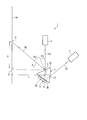
- FIG. 1 is a diagram for explaining the overall configuration of a refractive index measuring apparatus according to a first embodiment of the present invention.
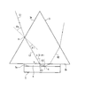
- FIG. 2 is a diagram for explaining a specific example of a refractive index calculation method in the refractive index measuring apparatus.
- FIG. 3 is a diagram for explaining a specific refractive index calculation method in the refractive index measuring apparatus when the solid sample is a single layer.
- FIG. 4 is a diagram for explaining another specific example of the refractive index calculation method in the refractive index measuring apparatus.
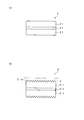
- Fig.5 (a) and FIG.5 (b) are the figures explaining the solid sample which consists of a laminated body.
- FIG. 5 (a) and FIG.5 (b) are the figures explaining the solid sample which consists of a laminated body.
- FIG. 6 is a diagram for explaining a specific method of calculating the refractive index in the refractive index measuring device when the solid sample is a laminate.
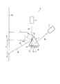
- FIG. 7 is a diagram for explaining the overall configuration of a refractive index measuring apparatus according to the second embodiment of the present invention.
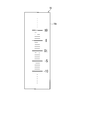
- FIG. 8 is a plan view showing the configuration of the scale shown in FIG.
- FIG. 9 is a diagram for explaining the overall configuration of a refractive index measurement apparatus according to the third embodiment of the present invention.
- FIG. 10 is a diagram for explaining the overall configuration of a refractive index measuring apparatus according to the fourth embodiment of the present invention.
- FIG. 11 is a plan view showing the configuration of the scale shown in FIG.
- FIG. 1 is a diagram for explaining the overall configuration of a refractive index measuring apparatus according to a first embodiment of the present invention.
- a light source 2 and a solid sample S as a measurement object having a predetermined refractive index and having a refractive index measured are interposed with a refractive index liquid 4.
- a prism 3 to be attached is provided.
- the refractive index measuring apparatus 1 of the present embodiment has a prism 3 mounted thereon, a rotation table 5 as a rotation driving unit that rotates the prism 3, and first reflected light R1 and second reflection described later.
- a scale 6 and a detector 7 for receiving the light R2 are provided.
- the light source 2 is fixed at a predetermined position, and is configured to cause the incident light L1 to enter the first surface 3a of the prism 3.
- the light source 2 is a light source that emits parallel light, preferably parallel light having a small area, as the incident light L1.
- a laser light source that emits laser light or a combination of a tube (lamp), a lens, and an aperture is used.
- the light source 2 and the prism 3 are irradiated with the incident light L1 on the first surface 3a of the prism 3 with respect to the rotation center O of the prism 3 (that is, the rotation axis of the rotary table 5).
- the light source 2 is installed such that the distance from the prism 3 is as small as possible. Thereby, even when the prism 3 is rotationally driven, it is possible to prevent the irradiation point of the incident light L1 on the first surface 3a from deviating from the rotation center O as much as possible.
- the prism 3 is made of a glass material having a predetermined refractive index, for example, 1.779.
- a regular triangular prism is used as the prism 3, and the prism 3 is attached with the solid sample S by the first surface 3 a on which the light L ⁇ b> 1 from the light source 2 is incident and the refractive index liquid 4.
- the solid sample S includes a second surface 3b that emits light L2 that has passed through the first surface 3a.
- the prism 3 is fixed to the rotary table 5 and is configured to be rotatable by the rotary table 5 with the solid sample S attached. Further, a handle (not shown), a motor (not shown) or the like is attached to the rotary table 5 so that the prism 3 is driven to rotate in the direction of a double arrow R in the figure.
- the refractive index liquid 4 a liquid having a predetermined refractive index is used, and the solid sample S is brought into close contact with the second surface 3 b of the prism 3 without interposing an air layer.
- the surface of the solid sample S on the prism 3 (refractive index liquid 4) side is not flat, that is, uneven. Even in the case of having a shape such as the above, in the measurement of the refractive index of the solid sample S, it is possible to reduce the adverse effect of the shape and to accurately measure the refractive index.
- the scale 6 constitutes a light receiving member having a light receiving surface 6a for receiving the first reflected light R1 reflected by the first surface 3a of the prism 3 out of the light from the light source 2.
- the light source 2 and the scale 6 are provided so that the light receiving surface 6 a is parallel to the incident light L 1 from the light source 2 to the prism 3.
- the light-receiving surface 6a comprised, for example in planar shape is used.
- the (light receiving) position A of the first reflected light R1 and the light receiving surface 6a perpendicular to the light receiving surface 6a from the position of the rotation center O of the prism 3 are perpendicular to each other.
- the distance to the position B is obtained. That is, the light receiving surface 6a is provided with a scale indicating the distance from the reference point in a direction parallel to the incident light L1 (vertical direction in the figure) with the orthogonal position B as a reference point. The distance to B can be discriminated.
- the refractive index of the solid sample S is obtained using the distance between them.
- the measurement accuracy of the refractive index of the solid sample S can be changed by changing the distance between the position of the rotation center O and the orthogonal position B ( Details will be described later.)
- the detector 7 receives the second reflected light R2 reflected from the surface Sa on the refractive index liquid 4 side of the solid sample S out of the light from the second surface 3b of the prism 3, and receives the received first light.
- the intensity of the two reflected light R2 is detected.
- a detector capable of detecting the intensity of the second reflected light R 2 such as a power meter or an illuminometer is used.
- the spectroscope is attached.
- a mirror may be installed between the surface Sa of the solid sample S and the detector 7 so that the second reflected light R2 is incident on the detector 7 via the mirror.
- a mirror can be installed on the optical path of the incident light L1 or on the optical path of the first reflected light R1.
- the refractive index of the solid sample S is measured by sequentially performing the following solid sample attaching step, light incident step, and refractive index detecting step. It is like that. Further, in the refractive index measuring apparatus 1 of the present embodiment, as will be described in detail later, not only a solid sample S made of a single layer having a constant refractive index but also a plurality of materials having different refractive indexes are used. Each refractive index of a plurality of materials in a solid sample made of a laminated body can be measured.
- the solid sample mounting step light that has passed through the first surface 3a is emitted from the prism 3 that has a predetermined refractive index and includes the first surface 3a on which light from the light source 2 is incident.
- the solid sample S is brought into close contact with the second surface 3b through the refractive index liquid 4 having a predetermined refractive index.
- incident light L1 from the light source 2 is incident on the first surface 3a of the prism 3, and the first reflected light R1 reflected by the first surface 3a is scaled (light receiving member) 6.
- the light receiving surface 6a receives light.
- the first reflected light R1 is reflected on the light receiving surface 6a side of the scale 6 at the rotation center O of the prism 3 on the first surface 3a of the prism 3, that is, the rotation center O of the prism 3.
- the light from the light source 2 is incident on the first surface 3a of the prism 3 so that the position becomes a light irradiation (incident) point.
- the incident light L1 from the light source 2 enters the first reflected light R1 and the prism 3, travels through the inside, and is emitted from the second surface 3b to the refractive index liquid 4 (solid sample S) side. It is divided into light L2.
- the light from the second surface 3b of the prism 3 is reflected by the surface Sa of the solid sample S on the refractive index liquid 4 side (that is, the interface between the prism 3 and the refractive index liquid 4).
- the second reflected light R2 is received by the detector 7. That is, in this light incident process, the light L2 that has passed through the prism 3 is incident on the surface Sa on which the solid sample S is attached with the refractive index liquid 4.
- the incident angle to the surface Sa is sufficiently large, all the light is reflected as the second reflected light R2 (total reflection), and when smaller than a certain value, a part of the light is reflected as the second reflected light R2.
- the light is reflected and part of the light propagates into the solid sample S.
- the second reflected light R ⁇ b> 2 is then emitted from the prism 3 and enters the detector 7.
- the refractive index detection step if the prism 3 to which the solid sample S is attached is rotated, and the incident angle to the first surface 3a where the intensity of the second reflected light R2 is smaller than a predetermined value is determined, Snell's
- the refractive index of the solid sample S can be calculated using the law.
- the prism 3 is rotated by the rotary table 5 with the solid sample S attached. Then, it is determined whether or not the intensity of the second reflected light R2 detected by the detector 7 is smaller than a predetermined value. When it is determined that the intensity is smaller than the predetermined value, the light receiving surface 6a of the scale 6 is used. The refractive index of the solid sample S is detected using the position A of the first reflected light R1.
- the intensity of the second reflected light R2 is detected by the detector 7 while rotating the prism 3, and a point where the intensity rapidly changes (a point where the intensity decreases rapidly) is found.
- the intensity of the second reflected light R2 is reduced from, for example, 7000 lux to about 1500 lux. In this case, for example, by setting 4000 lux as the predetermined value, it is possible to reliably determine the point at which the total reflection condition is broken.
- the incident angle from the position A of the first reflected light R1 to the solid sample S is calculated. Is the critical angle. Since the critical angle is determined by the refractive index of the material around the surface Sa of the solid sample S, the refractive index of the solid sample S can be obtained if the refractive index of the refractive index liquid 4 is known.
- the refractive index detection step of the present embodiment the position of the rotation center O and the orthogonal position B on the light receiving surface 6a that is perpendicular to the light receiving surface 6a of the scale 6 from the position of the rotation center O. And the distance between the orthogonal position B of the light receiving surface 6a and the position A of the first reflected light R1 on the light receiving surface 6a of the scale 6 to measure the refractive index of the solid sample S. It has become. That is, in this refractive index detection step, the refractive angle of the solid sample S is detected by obtaining the critical angle using the right triangle OAB shown in FIG.
- the rotation angle of the prism 3 per unit dimension on the light receiving surface 6a of the scale 6 decreases. Variations in the calculated refractive index of the solid sample S per unit dimension on the light receiving surface 6a are also reduced. That is, in this embodiment, the refractive index of the solid sample S can be obtained with higher accuracy as the distance between the position of the rotation center O and the orthogonal position B is increased.
- FIG. 2 is a diagram for explaining a specific example of a refractive index calculation method in the refractive index measuring apparatus.
- FIG. 3 is a diagram for explaining a specific refractive index calculation method in the refractive index measuring apparatus when the solid sample is a single layer.
- FIG. 4 is a diagram for explaining another specific example of the refractive index calculation method in the refractive index measuring apparatus.
- Fig.5 (a) and FIG.5 (b) are the figures explaining the solid sample which consists of a laminated body.
- FIG. 6 is a diagram for explaining a specific method of calculating the refractive index in the refractive index measuring device when the solid sample is a laminate.
- the distance L between the position of the rotation center O and the orthogonal position B is a known value. Further, the distance X between the orthogonal position B and the position A of the first reflected light R1 on the light receiving surface 6a can be read from a scale provided on the light receiving surface 6a. Therefore, the angle ⁇ can be obtained from the following equation (1).
- the incident angle ⁇ p of the incident light L1 from the light source 2 to the prism 3 can be obtained from the following equation (2).
- the incident angle ⁇ 2 of the light to the solid sample S is determined from the refraction angle ⁇ 1 of the light into the prism 3. That is, as shown in FIG. 3, the incident light L1 becomes light L2 that travels inside the prism 3 at point a (that is, the position of the rotation center O). The light L2 travels from the prism 3 to the inside of the refractive index liquid 4 at the point b, and is further reflected as the second reflected light R2 on the prism 3 side at the point c on the interface between the prism 3 and the refractive index liquid 4. .
- n1sin ⁇ 1 sin ⁇ p ⁇ (3)
- the refractive index of the refractive index liquid 4 is n2
- the following equation (4) is established when Snell's law is used at point b.
- n2sin ⁇ 2 n1sin ( ⁇ / 3 ⁇ 1) ⁇ (4) Therefore, if the refractive index n1 of the prism 3 and the refractive index n2 of the refractive index liquid 4 are known, the incident angle ⁇ 2 of light on the solid sample S can be calculated from the value of the distance X. In the state shown in FIGS. 2 and 3, the incident angle ⁇ 2 of the light to the solid sample S is the critical angle ⁇ c, and this critical angle ⁇ c is obtained when the refractive index of the solid sample S is n. It can be expressed by the following equation (5).
- the incident angle ⁇ 2 of the light to the solid sample S is the critical angle ⁇ c
- the position A ′ of the first reflected light R1 on the light receiving surface 6a as shown in FIG. May be below the orthogonal position B in the figure.
- the incident angle ⁇ p of the incident light L1 to the prism 3 may be calculated using the following equation (6) instead of the above equation (2).
- the above equations (3) to (5) may be used.
- the refractive index n2 of the refractive index liquid 4 is known, in such a case, the refractive index liquid 4 is changed to one having a refractive index larger than the refractive index n of the solid sample S, thereby The accurate refractive index n of the solid sample S can be detected.
- the solid sample S ' is composed of three layers S'1, S'2, and S'3 having different refractive indexes.
- the case where the refractive index of the layer S′1 is known and the refractive index of the intermediate layer S′2 is obtained will be described as an example.
- the solid sample S ′ is attached so that the layer S ′ 1 is in close contact with the second surface 3 b of the prism 3 with the refractive index liquid 4 interposed therebetween.
- the distance L between the position of the rotation center O and the orthogonal position B is a known value. Further, the distance X between the orthogonal position B and the position A of the first reflected light R1 on the light receiving surface 6a can be read from a scale provided on the light receiving surface 6a.
- the incident angle ⁇ p of the incident light L1 from the light source 2 to the prism 3 can be obtained from the above equation (2) as in the case of the solid sample S composed of a single layer. Further, as in the case of the solid sample S composed of a single layer, from the above equations (3) and (4) using Snell's law at points a and b, the refractive index liquid 4 side of the solid sample S ′ The incident angle ⁇ 2 of light on the solid sample S ′ at the point c on the surface S′1a (that is, the interface between the layer S′1 and the refractive index liquid 4) can be obtained.
- the refractive index of the layer S′1 is n3
- the refractive index of the intermediate layer S′2 to be measured is n
- the incident angle ⁇ 3 of the light to the intermediate layer S′2 is the distance X. It can be calculated from the value. Further, in the state shown in FIG. 6, the incident angle ⁇ 3 of the light to the intermediate layer S′2 is the critical angle ⁇ c, and this critical angle ⁇ c is set so that the refractive index of the intermediate layer S′2 is n. Sometimes, it can be expressed by the following equation (8).
- the distance X 276 mm
- ⁇ p 0.4135 rad
- ⁇ 1 0.278 rad
- ⁇ 2 0.9850 rad
- the prism is smaller than this refractive index n.
- the total reflection condition collapses at an angle at which the refractive index n1 of 3, the refractive index n2 of the refractive index liquid 4, or the refractive index n3 of the layer S′1 is detected, and the refractive index n of the intermediate layer S′2 is The refractive index n1 of the prism 3 smaller than the refractive index n, the refractive index n2 of the refractive index liquid 4, or the refractive index n3 of the layer S′1 is detected.
- the refractive index n1 of the prism 3, the refractive index n2 of the refractive index liquid 4, or the refractive index n3 of the layer S′1 is known, in such a case, the prism 3, the refractive index liquid 4, or the layer
- S′1 the refractive index larger than the refractive index n of the intermediate layer S′2
- the accurate refractive index n of the intermediate layer S′2 can be detected.
- the Snell's law is applied at the point d and the light incident angle of the layer S′3 is calculated, whereby the refractive index of the layer S′3 is calculated.
- the refractive index of the layer S′3 may be measured by bringing the layer S′3 into close contact with the second surface 3b of the prism 3 with the refractive index liquid 4 interposed therebetween.
- the solid sample S ′′ has three layers S ′′ 1, S ′′ 2, and S ′′ 3, and a minute protrusion S ′′ 1a is formed on the layer S ′′ 1.
- the refractive index of the intermediate layer S ′′ can be obtained with high accuracy by using the refractive index liquid 4 having the same refractive index as that of the layer S ′′ 1.
- the refractive index measuring apparatus 1 of the present embodiment it is desirable to perform calibration in order to obtain the value of the distance L more accurately. That is, the measurement is performed in a state where only the refractive index liquid 4 having a known refractive index is in close contact with the second surface 3b of the prism 3 or in contact with only the air without the refractive index liquid 4 being in close contact. By doing so, the value of the distance L can be obtained more accurately, and the position of each part of the refractive index measuring device 1 such as the scale 6 can be made appropriate.
- the refractive index of the solid sample S is measured using the position A of the first reflected light R1 on the light receiving surface 6a of the scale (light receiving member) 6.
- the light source 2 and the prism 3 are configured such that the first reflected light R1 is reflected to the light receiving surface 6a side of the scale at the rotation center O of the prism 3 on the first surface 3a of the prism 3. , Provided. Further, in this embodiment, the distance between the position of the rotation center O and the orthogonal position B on the light receiving surface 6a that is perpendicular to the light receiving surface 6a of the scale 6 from the position of the rotation center O.
- the refractive index of the solid sample S is measured using L and the distance X between the orthogonal position B of the light receiving surface 6a and the position A of the first reflected light R1 on the light receiving surface 6a of the scale 6. Thereby, the refractive index of the solid sample S can be obtained easily.
- FIG. 7 is a diagram for explaining the overall configuration of a refractive index measuring apparatus according to the second embodiment of the present invention.
- FIG. 8 is a plan view showing the configuration of the scale shown in FIG.
- the main difference between this embodiment and the first embodiment is that the reference position of the first reflected light when the refractive index of the solid sample is the reference refractive index, and every predetermined interval.
- This is a point using a scale (light receiving member) which is provided and has a light receiving surface on which a scale indicating a deviation position with respect to the reference position is installed.
- symbol is attached
- the incident light L1 from the light source 2 to the prism 3 is reflected as the first reflected light R1 at the rotation center O of the prism 3.
- the light is received by the light receiving surface 16 a of the scale (light receiving member) 16.
- the light L2 that has traveled into the prism 3 at the rotation center O of the prism 3 is reflected as the second reflected light R2 on the surface Sa of the solid sample S on the refractive index liquid 4 side, and is received by the detector 7. ing.
- the light receiving surface 16a of the scale 16 is provided at the reference position St of the first reflected light R1 when the refractive index of the solid sample S is the reference refractive index, and at predetermined intervals.
- a scale indicating a shift position with respect to the reference position St is provided. This scale measures the refractive index of a substance having a known refractive index and determines the measurement result as the reference position St.
- the refractive index liquid 4 having a known refractive index is brought into close contact with the second surface 3b of the prism 3, or in a state where the refractive index liquid 4 is not brought into close contact with only the air.
- the (light receiving) position A of the first reflected light R1 is set on the light receiving surface 16a as the reference position St, and the position on the light receiving surface 16a is obtained, for example, in increments of 0.001 as shown in FIG.
- a scale is installed.
- a correlation table between each position of the scale and the value of the refractive index is prepared in advance, and the scale installed on the light receiving surface 16a of the scale 16 is read during the refractive index detection step.
- the refractive index of the solid sample S is measured by referring to the correlation table. That is, the refractive index of the solid sample S can be obtained by obtaining the deviation position with respect to the reference position St and referring to the correlation table.
- the present embodiment can achieve the same operations and effects as the first embodiment. Further, on the light receiving surface 6a of the scale (light receiving member) 16 of the present embodiment, the reference position St of the first reflected light R1 when the refractive index of the solid sample S is the reference refractive index, and every predetermined interval. And a scale indicating a shift position with respect to the reference position St is provided. Thereby, in this embodiment, the refractive index of the solid sample S can be calculated
- FIG. 9 is a diagram for explaining the overall configuration of a refractive index measurement apparatus according to the third embodiment of the present invention.
- the main difference between this embodiment and the second embodiment is that a light source and a scale (light receiving member) are provided so that the light receiving surface is orthogonal to the incident light from the light source to the prism. is there.
- symbol is attached
- the incident light L1 from the light source 2 to the prism 3 is reflected as the first reflected light R1 at the rotation center O of the prism 3 as in the second embodiment.
- the light is received by the light receiving surface 26 a of the scale 26.
- the light L2 that has traveled into the prism 3 at the rotation center O of the prism 3 is reflected as the second reflected light R2 on the surface Sa of the solid sample S on the refractive index liquid 4 side, and is received by the detector 7. ing.
- the present embodiment can achieve the same operations and effects as those of the second embodiment.
- FIG. 10 is a diagram for explaining the overall configuration of a refractive index measuring apparatus according to the fourth embodiment of the present invention.
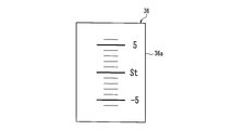
- FIG. 11 is a plan view showing the configuration of the scale shown in FIG.
- the main difference between the present embodiment and the second embodiment is that a scale (light receiving member) having a light receiving surface provided with a scale corresponding to a refractive index within an allowable range in a solid sample. This is the point used.
- symbol is attached
- the incident light L1 from the light source 2 to the prism 3 is reflected as the first reflected light R1 at the rotation center O of the prism 3.
- the light is received by the light receiving surface 36 a of the scale (light receiving member) 36.
- the light L2 that has traveled into the prism 3 at the rotation center O of the prism 3 is reflected as the second reflected light R2 on the surface Sa of the solid sample S on the refractive index liquid 4 side, and is received by the detector 7. ing.
- a scale corresponding to the refractive index within the allowable range of the solid sample S is provided on the light receiving surface 36a of the scale 36. That is, on the light receiving surface 36a, as in the second embodiment, the reference position St of the first reflected light R1 when the refractive index of the solid sample S is the reference refractive index, and every predetermined interval. And a scale indicating a shift position with respect to the reference position St is provided. Further, in the scale 36, the scale of the light receiving surface 36a corresponds to the refractive index within the allowable range of the solid sample.
- the refractive index of the solid sample S is measured using a scale corresponding to the refractive index within the allowable range of the solid sample S. That is, in the refractive index detection step, when the first reflected light R1 is received on the light receiving surface 36a, the refractive index of the solid sample S is obtained based on the light receiving position. Further, the refractive index of the solid sample S is within an allowable range, and it can be determined that the solid sample S can be used as a product.
- the refractive index detection step when the first reflected light R1 is not received on the light receiving surface 36a, it is determined that the refractive index of the solid sample S is outside the allowable range, and the solid sample S cannot be used as a product. be able to.
- the present embodiment can achieve the same operations and effects as those of the second embodiment. Further, on the light receiving surface 36a of the scale (light receiving member) 36 of the present embodiment, a scale corresponding to the refractive index within the allowable range of the solid sample S is provided. Thereby, in this embodiment, the pass / fail determination about the refractive index in the solid sample S can be performed immediately, and the inspection process of the solid sample S can be simplified.
- the light source and the prism are provided so that the first reflected light is reflected to the light receiving surface side of the scale (light receiving member) at the rotation center of the prism on the first surface of the prism.
- the present invention is not limited to this, as long as light from the light source is incident on the first surface of the prism having a predetermined refractive index.
- the light source and the prism are provided such that the first reflected light is reflected to the light receiving surface side of the light receiving member at the rotation center of the prism on the first surface of the prism. Is preferable in that the refractive index of the solid sample can be easily calculated.
- the position of the rotation center and the position of the rotation center to the light receiving surface of the light receiving member The distance between the perpendicular position on the light receiving surface and the perpendicular position on the light receiving surface, and the distance between the orthogonal position of the light receiving surface and the position of the first reflected light on the light receiving surface of the light receiving member, This is because the refractive index of the sample can be easily obtained.
- the case where the light source and the scale (light receiving member) are provided so that the light receiving surface is parallel to the incident light from the light source to the prism is described. did.
- the case where the light source and the scale (light receiving member) are provided so that the light receiving surface is orthogonal to the incident light from the light source to the prism has been described.
- the light source and the light receiving member of the present invention are not particularly limited as long as the light reflected by the first surface of the prism is received by the light receiving surface of the light receiving member.
- the light receiving member of the present invention is the first surface of the prism out of the light from the light source.
- a recessed light receiving member having a light receiving surface configured in a spherical shape may be used.
- the prism of the present invention has a predetermined refractive index and a first surface on which light from a light source is incident and a solid sample.
- the prism of an isosceles triangular prism can also be used.
- the case of using a regular triangular prism is preferable in that the refractive index of a solid sample can be easily obtained as compared with the case of using a prism of another shape. .
- the present invention is useful for a refractive index measuring apparatus and a refractive index measuring method that can improve the measurement accuracy of the refractive index of a solid sample.
Landscapes
- Physics & Mathematics (AREA)
- Health & Medical Sciences (AREA)
- Life Sciences & Earth Sciences (AREA)
- Chemical & Material Sciences (AREA)
- Analytical Chemistry (AREA)
- Biochemistry (AREA)
- General Health & Medical Sciences (AREA)
- General Physics & Mathematics (AREA)
- Immunology (AREA)
- Pathology (AREA)
- Investigating Or Analysing Materials By Optical Means (AREA)
Abstract
Description
光源と、
所定の屈折率を有するとともに、前記光源からの光を入射する第1面及び前記固体試料に対して、前記第1面を通過した光を出射する第2面を備えたプリズムと、
前記プリズムを回転駆動する回転駆動部と、
所定の屈折率を有するとともに、前記プリズムの前記第2面に対し、前記固体試料を密着させる屈折率液と、
前記光源からの光のうち、前記プリズムの前記第1面にて反射された第1反射光を受光する受光面を有する受光部材と、
前記プリズムの前記第2面からの光のうち、前記固体試料の前記屈折率液側の表面にて反射された第2反射光を受光して、その受光した第2反射光の強度を検出する検出器を備え、
前記プリズムが前記回転駆動部によって回転駆動されて、前記検出器にて検出された第2反射光の強度が所定値よりも小さくなった場合に、前記受光部材の前記受光面での第1反射光の位置を用いて、前記固体試料の屈折率を測定することを特徴とするものである。
前記回転中心の位置とこの回転中心の位置から前記受光部材の前記受光面に対して、垂線を下ろした先の当該受光面での直交位置との間の距離、及び前記受光面の前記直交位置と前記受光部材の前記受光面での第1反射光の位置との間の距離を用いて、前記固体試料の屈折率を測定することが好ましい。
所定の屈折率を有するとともに、光源からの光が入射される第1面を備えたプリズムにおいて、前記第1面を通過した光を出射する第2面に対して、所定の屈折率を有する屈折率液を介在させて前記固体試料を密着させる固体試料取付工程と、
前記光源からの光を前記プリズムの前記第1面に入射させて、当該第1面にて反射された第1反射光を受光部材の受光面で受光するとともに、前記プリズムの前記第2面からの光のうち、前記固体試料の前記屈折率液側の表面にて反射された第2反射光を検出器で受光する光入射工程と、
前記固体試料を取り付けた状態で、前記プリズムを回転させるとともに、前記検出器で検出した第2反射光の強度が所定値よりも小さくなるか否かについて判別し、前記所定値よりも小さくなったことを判別した場合に、前記受光部材の前記受光面での第1反射光の位置を用いて、前記固体試料の屈折率を検出する屈折率検出工程とを備えていることを特徴とするものである。
前記屈折率検出工程において、前記回転中心の位置とこの回転中心の位置から前記受光部材の前記受光面に対して、垂線を下ろした先の当該受光面での直交位置との間の距離、及び前記受光面の前記直交位置と前記受光部材の前記受光面での第1反射光の位置との間の距離を用いて、前記固体試料の屈折率を測定することが好ましい。
図1は、本発明の第1の実施形態にかかる屈折率測定装置の全体構成を説明する図である。図において、本実施形態の屈折率測定装置1には、光源2と、所定の屈折率を有するとともに、屈折率が測定される被測定物としての固体試料Sが屈折率液4を介在させて取り付けられるプリズム3とが設けられている。また、本実施形態の屈折率測定装置1は、プリズム3が載置されるとともに、当該プリズム3を回転駆動させる回転駆動部としての回転テーブル5と、後述の第1反射光R1及び第2反射光R2をそれぞれ受光するスケール6及び検出器7を備えている。
また、プリズム3への光源2からの入射光L1の入射角θpは、次の(2)式より求めることができる。
さらに、図3を参照して、プリズム3の内部への光の屈折角θ1から固体試料Sへの光の入射角θ2を求める。すなわち、図3に示すように、入射光L1は、a点(つまり、回転中心Oの位置)でプリズム3の内部を進む光L2となる。そして、この光L2は、b点でプリズム3から屈折率液4の内部に進み、さらにプリズム3と屈折率液4の界面上のc点でプリズム3側に第2反射光R2として反射される。
また、屈折率液4の屈折率をn2とすると、b点にてスネルの法則を用いたとき、次の(4)式が成立する。
従って、プリズム3の屈折率n1と屈折率液4の屈折率n2が既知であれば、固体試料Sへの光の入射角θ2は距離Xの値より計算可能である。また、図2及び図3に示す状態では、固体試料Sへの光の入射角θ2が臨界角θcとなっており、この臨界角θcは、固体試料Sの屈折率をnとしたときに、次の(5)式で表すことができる。
さらに、図2及び図3に示す状態、すなわち第2反射光R2の強度が所定値よりも小さくなったことを判別した場合では、θc=θ2なので、距離Xの値から固体試料Sの屈折率nを求めることができる。
屈折率液4の屈折率n2が、固体試料Sの屈折率nよりも小さい場合、この屈折率nよりも小さい屈折率液4の屈折率n2が検出される角度にて全反射条件が崩れて、固体試料Sの屈折率nとして、この屈折率nよりも小さい屈折率液4の屈折率n2が検出される。この屈折率液4の屈折率n2は既知であるため、このような場合には、屈折率液4を、固体試料Sの屈折率nよりも大きい屈折率を有するものに変更することにより、当該固体試料Sの正確な屈折率nを検出することができる。
従って、プリズム3の屈折率n1、屈折率液4の屈折率n2、及び層S’1の屈折率n3が既知であれば、中間の層S’2への光の入射角θ3は距離Xの値より計算可能である。また、図6に示す状態では、中間の層S’2への光の入射角θ3が臨界角θcとなっており、この臨界角θcは、中間の層S’2の屈折率をnとしたときに、次の(8)式で表すことができる。
さらに、図6に示す状態、すなわち第2反射光R2の強度が所定値よりも小さくなったことを判別した場合では、θc=θ3なので、距離Xの値から中間の層S’2の屈折率nを求めることができる。
図7は、本発明の第2の実施形態にかかる屈折率測定装置の全体構成を説明する図である。図8は、図7に示したスケールの構成を示す平面図である。図において、本実施形態と上記第1の実施形態との主な相違点は、固体試料の屈折率が基準の屈折率である場合での第1反射光の基準位置、及び所定の間隔毎に設けられるとともに、基準位置に対するずれ位置を示す目盛りが設置された受光面を有するスケール(受光部材)を用いた点である。なお、上記第1の実施形態と共通する要素については、同じ符号を付して、その重複した説明を省略する。
図9は、本発明の第3の実施形態にかかる屈折率測定装置の全体構成を説明する図である。図において、本実施形態と上記第2の実施形態との主な相違点は、受光面が光源からプリズムへの入射光に対し直交するように、光源とスケール(受光部材)を設けた点である。なお、上記第2の実施形態と共通する要素については、同じ符号を付して、その重複した説明を省略する。
図10は、本発明の第4の実施形態にかかる屈折率測定装置の全体構成を説明する図である。図11は、図10に示したスケールの構成を示す平面図である。図において、本実施形態と上記第2の実施形態との主な相違点は、固体試料での許容される範囲内の屈折率に対応した目盛りを設けた受光面を有するスケール(受光部材)を用いた点である。なお、上記第2の実施形態と共通する要素については、同じ符号を付して、その重複した説明を省略する。
2 光源
3 プリズム
3a 第1面
3b 第2面
4 屈折率液
5 回転テーブル(回転駆動部)
6、16、26、36 スケール(受光部材)
6a、16a、26a、36a 受光面
7 検出器
S、S’、S” 固体試料
R1 第1反射光
R2 第2反射光
Claims (9)
- 固体試料の屈折率を測定する屈折率測定装置であって、
光源と、
所定の屈折率を有するとともに、前記光源からの光を入射する第1面及び前記固体試料に対して、前記第1面を通過した光を出射する第2面を備えたプリズムと、
前記プリズムを回転駆動する回転駆動部と、
所定の屈折率を有するとともに、前記プリズムの前記第2面に対し、前記固体試料を密着させる屈折率液と、
前記光源からの光のうち、前記プリズムの前記第1面にて反射された第1反射光を受光する受光面を有する受光部材と、
前記プリズムの前記第2面からの光のうち、前記固体試料の前記屈折率液側の表面にて反射された第2反射光を受光して、その受光した第2反射光の強度を検出する検出器を備え、
前記プリズムが前記回転駆動部によって回転駆動されて、前記検出器にて検出された第2反射光の強度が所定値よりも小さくなった場合に、前記受光部材の前記受光面での第1反射光の位置を用いて、前記固体試料の屈折率を測定する、
ことを特徴とする屈折率測定装置。 - 前記光源と前記プリズムは、第1反射光が前記プリズムの前記第1面での当該プリズムの回転中心にて前記受光部材の前記受光面側に反射されるように、設けられ、
前記回転中心の位置とこの回転中心の位置から前記受光部材の前記受光面に対して、垂線を下ろした先の当該受光面での直交位置との間の距離、及び前記受光面の前記直交位置と前記受光部材の前記受光面での第1反射光の位置との間の距離を用いて、前記固体試料の屈折率を測定する請求項1に記載の屈折率測定装置。 - 前記受光部材の前記受光面には、前記固体試料の屈折率が基準の屈折率である場合での第1反射光の基準位置、及び所定の間隔毎に設けられるとともに、前記基準位置に対するずれ位置を示す目盛りが設置されている請求項1または2に記載の屈折率測定装置。
- 前記受光部材の前記受光面では、前記固体試料での許容される範囲内の屈折率に対応した目盛りが設けられている請求項3に記載の屈折率測定装置。
- 前記プリズムとして、正三角柱のプリズムが用いられている請求項1~4のいずれか1項に記載の屈折率測定装置。
- 固体試料の屈折率を測定する屈折率測定方法であって、
所定の屈折率を有するとともに、光源からの光が入射される第1面を備えたプリズムにおいて、前記第1面を通過した光を出射する第2面に対して、所定の屈折率を有する屈折率液を介在させて前記固体試料を密着させる固体試料取付工程と、
前記光源からの光を前記プリズムの前記第1面に入射させて、当該第1面にて反射された第1反射光を受光部材の受光面で受光するとともに、前記プリズムの前記第2面からの光のうち、前記固体試料の前記屈折率液側の表面にて反射された第2反射光を検出器で受光する光入射工程と、
前記固体試料を取り付けた状態で、前記プリズムを回転させるとともに、前記検出器で検出した第2反射光の強度が所定値よりも小さくなるか否かについて判別し、前記所定値よりも小さくなったことを判別した場合に、前記受光部材の前記受光面での第1反射光の位置を用いて、前記固体試料の屈折率を検出する屈折率検出工程と、
を備えていることを特徴とする屈折率測定方法。 - 前記光入射工程において、第1反射光が前記プリズムの前記第1面での当該プリズムの回転中心にて前記受光部材の前記受光面側に反射されるように、前記光源からの光を前記プリズムの前記第1面に入射させ、
前記屈折率検出工程において、前記回転中心の位置とこの回転中心の位置から前記受光部材の前記受光面に対して、垂線を下ろした先の当該受光面での直交位置との間の距離、及び前記受光面の前記直交位置と前記受光部材の前記受光面での第1反射光の位置との間の距離を用いて、前記固体試料の屈折率を測定する請求項6に記載の屈折率測定方法。 - 前記屈折率検出工程において、前記受光部材の前記受光面に設置された目盛りを用いて、前記固体試料の屈折率を測定する請求項6または請求項7に記載の屈折率測定方法。
- 前記屈折率検出工程において、前記固体試料での許容される範囲内の屈折率に対応した目盛りを用いて、前記固体試料の屈折率を測定する請求項8に記載の屈折率測定方法。
Priority Applications (3)
| Application Number | Priority Date | Filing Date | Title |
|---|---|---|---|
| JP2012533972A JPWO2012036075A1 (ja) | 2010-09-16 | 2011-09-09 | 屈折率測定装置、及び屈折率測定方法 |
| CN201180044568.8A CN103119420B (zh) | 2010-09-16 | 2011-09-09 | 折射率测定装置和折射率测定方法 |
| US13/823,144 US8947650B2 (en) | 2010-09-16 | 2011-09-09 | Refractive index measuring device and refractive index measuring method |
Applications Claiming Priority (2)
| Application Number | Priority Date | Filing Date | Title |
|---|---|---|---|
| JP2010208125 | 2010-09-16 | ||
| JP2010-208125 | 2010-09-16 |
Publications (1)
| Publication Number | Publication Date |
|---|---|
| WO2012036075A1 true WO2012036075A1 (ja) | 2012-03-22 |
Family
ID=45831538
Family Applications (1)
| Application Number | Title | Priority Date | Filing Date |
|---|---|---|---|
| PCT/JP2011/070549 Ceased WO2012036075A1 (ja) | 2010-09-16 | 2011-09-09 | 屈折率測定装置、及び屈折率測定方法 |
Country Status (4)
| Country | Link |
|---|---|
| US (1) | US8947650B2 (ja) |
| JP (1) | JPWO2012036075A1 (ja) |
| CN (1) | CN103119420B (ja) |
| WO (1) | WO2012036075A1 (ja) |
Cited By (1)
| Publication number | Priority date | Publication date | Assignee | Title |
|---|---|---|---|---|
| CN106323810A (zh) * | 2016-11-14 | 2017-01-11 | 宜兴市晶科光学仪器有限公司 | 一种用于尿液检测的比重折射管 |
Families Citing this family (11)
| Publication number | Priority date | Publication date | Assignee | Title |
|---|---|---|---|---|
| US8692985B1 (en) * | 2012-11-19 | 2014-04-08 | J.A. Woollam Co., Inc. | Method of determining refractive index of prism shaped material |
| JP6217748B2 (ja) * | 2013-06-24 | 2017-10-25 | 株式会社島津製作所 | 屈折率測定装置 |
| US9632023B2 (en) * | 2013-07-04 | 2017-04-25 | Shimadzu Corporation | V-block refractometer |
| US9494410B2 (en) | 2013-12-05 | 2016-11-15 | National Taiwan University | Method for measuring characteristics of sample |
| CN104034693B (zh) * | 2014-05-08 | 2017-03-01 | 新疆大学 | 一种基于反射光强的多孔硅微腔生物传感器检测生物分子的方法 |
| CN106290254B (zh) * | 2016-07-22 | 2018-10-30 | 京东方科技集团股份有限公司 | 一种折射率测量设备、折射率测量方法和装置 |
| US10001551B1 (en) * | 2016-12-19 | 2018-06-19 | Waymo Llc | Mirror assembly |
| US10948573B2 (en) | 2016-12-19 | 2021-03-16 | Waymo Llc | Mirror assembly |
| US11536845B2 (en) | 2018-10-31 | 2022-12-27 | Waymo Llc | LIDAR systems with multi-faceted mirrors |
| US10976420B2 (en) | 2018-11-02 | 2021-04-13 | Waymo Llc | Methods and systems for detecting sensor occlusions |
| CN112986190B (zh) * | 2021-02-24 | 2022-01-28 | 中国科学院长春光学精密机械与物理研究所 | 反射率测量装置 |
Citations (4)
| Publication number | Priority date | Publication date | Assignee | Title |
|---|---|---|---|---|
| JPS52102769U (ja) * | 1976-01-30 | 1977-08-04 | ||
| JPS52135757A (en) * | 1976-05-07 | 1977-11-14 | Kubota Ltd | Device for indication of mass or the like |
| JPS6351260B2 (ja) * | 1979-09-18 | 1988-10-13 | Nippon Electric Co | |
| JPH06288902A (ja) * | 1993-03-31 | 1994-10-18 | Sony Corp | 減衰全反射型薄膜評価装置 |
Family Cites Families (8)
| Publication number | Priority date | Publication date | Assignee | Title |
|---|---|---|---|---|
| US4692024A (en) * | 1985-05-10 | 1987-09-08 | Electro-Tec Corporation | Automatic refractometer |
| JPH0954039A (ja) | 1995-08-14 | 1997-02-25 | S I C:Kk | 示差屈折計 |
| CN1254837A (zh) * | 1998-11-20 | 2000-05-31 | 中国科学院西安光学精密机械研究所 | 液体折射率检测装置 |
| ES2261009B1 (es) * | 2004-06-11 | 2007-11-16 | Consejo Superior De Investigaciones Cientificas. | Dispositivo y metodo para detectar cambios en el indice de refraccion de un medio dielectrico. |
| JP5332202B2 (ja) | 2007-12-28 | 2013-11-06 | 花王株式会社 | 屈折率測定方法 |
| CN201259492Y (zh) * | 2008-10-15 | 2009-06-17 | 熊雪 | 多功能折射率测量尺 |
| US8379228B1 (en) * | 2010-02-16 | 2013-02-19 | Alan Douglas Streater | Apparatus for measuring thin film refractive index and thickness with a spectrophotometer |
| JP6351260B2 (ja) * | 2013-12-26 | 2018-07-04 | キヤノン株式会社 | 撮像装置およびその制御方法 |
-
2011
- 2011-09-09 WO PCT/JP2011/070549 patent/WO2012036075A1/ja not_active Ceased
- 2011-09-09 CN CN201180044568.8A patent/CN103119420B/zh not_active Expired - Fee Related
- 2011-09-09 JP JP2012533972A patent/JPWO2012036075A1/ja not_active Withdrawn
- 2011-09-09 US US13/823,144 patent/US8947650B2/en not_active Expired - Fee Related
Patent Citations (4)
| Publication number | Priority date | Publication date | Assignee | Title |
|---|---|---|---|---|
| JPS52102769U (ja) * | 1976-01-30 | 1977-08-04 | ||
| JPS52135757A (en) * | 1976-05-07 | 1977-11-14 | Kubota Ltd | Device for indication of mass or the like |
| JPS6351260B2 (ja) * | 1979-09-18 | 1988-10-13 | Nippon Electric Co | |
| JPH06288902A (ja) * | 1993-03-31 | 1994-10-18 | Sony Corp | 減衰全反射型薄膜評価装置 |
Cited By (1)
| Publication number | Priority date | Publication date | Assignee | Title |
|---|---|---|---|---|
| CN106323810A (zh) * | 2016-11-14 | 2017-01-11 | 宜兴市晶科光学仪器有限公司 | 一种用于尿液检测的比重折射管 |
Also Published As
| Publication number | Publication date |
|---|---|
| JPWO2012036075A1 (ja) | 2014-02-03 |
| US20130182245A1 (en) | 2013-07-18 |
| US8947650B2 (en) | 2015-02-03 |
| CN103119420B (zh) | 2015-05-27 |
| CN103119420A (zh) | 2013-05-22 |
Similar Documents
| Publication | Publication Date | Title |
|---|---|---|
| WO2012036075A1 (ja) | 屈折率測定装置、及び屈折率測定方法 | |
| CN1226590C (zh) | 薄膜厚度测量装置及反射系数测量装置和方法 | |
| US10145785B2 (en) | Optical element rotation type Mueller-matrix ellipsometer and method for measuring Mueller-matrix of sample using the same | |
| TWI746944B (zh) | 用於特徵化彎曲部件的稜鏡耦合系統及方法 | |
| CN107941477B (zh) | 一种能精确控制入射角的分光镜测量方法及装置 | |
| JP2011013145A5 (ja) | ||
| CN103439294A (zh) | 角度调制与波长调制spr共用系统 | |
| TWI384213B (zh) | 光學異向性參數測量方法及測量裝置 | |
| JP2008170344A (ja) | 防眩性の評価方法及び測定装置 | |
| KR101426603B1 (ko) | 화상 취득 장치 및 화상 취득 방법 | |
| CN215833253U (zh) | 一种基于光束偏转器的角度调制型spr传感器及spr检测设备 | |
| JP2009222441A (ja) | 再帰反射性強度測定装置 | |
| US20250231085A1 (en) | Waveguide measurement device | |
| CN216594769U (zh) | 一种快速透反射测量仪 | |
| CN217561355U (zh) | 运动极片表面缺陷检测装置 | |
| JP2004061419A (ja) | 測定装置 | |
| JP6197796B2 (ja) | 検出装置 | |
| CN115452771A (zh) | 一种快速透反射测量仪 | |
| CN223741930U (zh) | 检测装置 | |
| JP4728830B2 (ja) | 光学的異方性パラメータ測定方法及び測定装置 | |
| JP2009139279A (ja) | 検査装置 | |
| US20100182595A1 (en) | Three dimensional light measuring apparatus | |
| JP4710510B2 (ja) | 配向計 | |
| JP2013072868A (ja) | 表面プラズモン共鳴センサシステム | |
| KR102950027B1 (ko) | 박막 특성 측정장치 |
Legal Events
| Date | Code | Title | Description |
|---|---|---|---|
| WWE | Wipo information: entry into national phase |
Ref document number: 201180044568.8 Country of ref document: CN |
|
| 121 | Ep: the epo has been informed by wipo that ep was designated in this application |
Ref document number: 11825078 Country of ref document: EP Kind code of ref document: A1 |
|
| WWE | Wipo information: entry into national phase |
Ref document number: 2012533972 Country of ref document: JP |
|
| WWE | Wipo information: entry into national phase |
Ref document number: 13823144 Country of ref document: US |
|
| NENP | Non-entry into the national phase |
Ref country code: DE |
|
| 122 | Ep: pct application non-entry in european phase |
Ref document number: 11825078 Country of ref document: EP Kind code of ref document: A1 |