WO2012032933A1 - オイルセパレータ - Google Patents
オイルセパレータ Download PDFInfo
- Publication number
- WO2012032933A1 WO2012032933A1 PCT/JP2011/069059 JP2011069059W WO2012032933A1 WO 2012032933 A1 WO2012032933 A1 WO 2012032933A1 JP 2011069059 W JP2011069059 W JP 2011069059W WO 2012032933 A1 WO2012032933 A1 WO 2012032933A1
- Authority
- WO
- WIPO (PCT)
- Prior art keywords
- gas
- cyclone chamber
- cyclone
- oil
- blow
- Prior art date
- Legal status (The legal status is an assumption and is not a legal conclusion. Google has not performed a legal analysis and makes no representation as to the accuracy of the status listed.)
- Ceased
Links
Images





Classifications
-
- F—MECHANICAL ENGINEERING; LIGHTING; HEATING; WEAPONS; BLASTING
- F01—MACHINES OR ENGINES IN GENERAL; ENGINE PLANTS IN GENERAL; STEAM ENGINES
- F01M—LUBRICATING OF MACHINES OR ENGINES IN GENERAL; LUBRICATING INTERNAL COMBUSTION ENGINES; CRANKCASE VENTILATING
- F01M13/00—Crankcase ventilating or breathing
- F01M13/04—Crankcase ventilating or breathing having means for purifying air before leaving crankcase, e.g. removing oil
-
- F—MECHANICAL ENGINEERING; LIGHTING; HEATING; WEAPONS; BLASTING
- F01—MACHINES OR ENGINES IN GENERAL; ENGINE PLANTS IN GENERAL; STEAM ENGINES
- F01M—LUBRICATING OF MACHINES OR ENGINES IN GENERAL; LUBRICATING INTERNAL COMBUSTION ENGINES; CRANKCASE VENTILATING
- F01M13/00—Crankcase ventilating or breathing
- F01M2013/0038—Layout of crankcase breathing systems
- F01M2013/005—Layout of crankcase breathing systems having one or more deoilers
- F01M2013/0061—Layout of crankcase breathing systems having one or more deoilers having a plurality of deoilers
-
- F—MECHANICAL ENGINEERING; LIGHTING; HEATING; WEAPONS; BLASTING
- F01—MACHINES OR ENGINES IN GENERAL; ENGINE PLANTS IN GENERAL; STEAM ENGINES
- F01M—LUBRICATING OF MACHINES OR ENGINES IN GENERAL; LUBRICATING INTERNAL COMBUSTION ENGINES; CRANKCASE VENTILATING
- F01M13/00—Crankcase ventilating or breathing
- F01M2013/0038—Layout of crankcase breathing systems
- F01M2013/005—Layout of crankcase breathing systems having one or more deoilers
- F01M2013/0061—Layout of crankcase breathing systems having one or more deoilers having a plurality of deoilers
- F01M2013/0072—Layout of crankcase breathing systems having one or more deoilers having a plurality of deoilers in series
-
- F—MECHANICAL ENGINEERING; LIGHTING; HEATING; WEAPONS; BLASTING
- F01—MACHINES OR ENGINES IN GENERAL; ENGINE PLANTS IN GENERAL; STEAM ENGINES
- F01M—LUBRICATING OF MACHINES OR ENGINES IN GENERAL; LUBRICATING INTERNAL COMBUSTION ENGINES; CRANKCASE VENTILATING
- F01M13/00—Crankcase ventilating or breathing
- F01M13/04—Crankcase ventilating or breathing having means for purifying air before leaving crankcase, e.g. removing oil
- F01M2013/0422—Separating oil and gas with a centrifuge device
- F01M2013/0427—Separating oil and gas with a centrifuge device the centrifuge device having no rotating part, e.g. cyclone
Definitions
- the present invention relates to an oil separator, and more particularly to an oil separator that collects oil mist in blow-by gas generated in an engine crankcase of an internal combustion engine such as an automobile engine.
- the oil separator includes a plurality of cyclone chambers arranged in a row in which a flow of blow-by gas forms a cyclone, and a blow-by gas rectifying chamber arranged in parallel with the cyclone chamber and on an upper side surface of the cyclone chamber,
- the blow-by gas inlet is formed in front of the cyclone chambers, and the outer peripheral wall of the upper part of the cyclone chamber facing the rectifying chamber is a partition wall separating the rectifying chamber and the cyclone chamber.
- the partition wall is formed with a slit that serves as an inlet of the blow-by gas into the cyclone chamber in parallel to the axial direction of the cyclone chamber, and the blow-by gas that flows into the rectifying chamber and flows along the outer wall surface or the partition wall is slit. From the outer circumferential wall of the cyclone chamber along the inner surface of the cyclone chamber.
- the present invention provides an oil separator that can reliably capture fine oil mist and improve oil mist capture performance.
- a gas inlet for introducing blowby gas for introducing blowby gas
- a gas outlet for discharging blowby gas for discharging blowby gas
- a gas flow path of the blowby gas between the gas inlet and the gas outlet for introducing blowby gas
- an oil separator having a plurality of cyclone chambers connected to each other and having a flow of the blowby gas as a cyclone, and a collision wall provided inside the plurality of cyclone chambers and blocking a part of the flow of the blowby gas.
- the blow-by gas introduced into the oil separator from the gas introduction port becomes a cyclone inside the plurality of cyclone chambers connected along the gas flow path, and is provided inside the cyclone chamber. Part of the flow is blocked by the collision wall, and then discharged from the gas outlet. For this reason, the oil mist of fine particles is also reliably captured by the plurality of cyclone chambers and the collision wall inside each cyclone chamber, and the oil mist capturing performance is improved.
- the plurality of cyclone chambers are divided into an upper part and a lower part by a spiral upper and lower separation wall, and the upper part and the lower part are separated from each other.
- the upper portion and the lower portion of the cyclone chamber on the upstream side and the cyclone chamber on the downstream side of the gas flow path may be alternately connected.
- the blow-by gas introduced into the oil separator from the gas introduction port is divided into an upper part and a lower part by the spiral upper and lower separation walls, and the upper part and the lower part are communicated by the opening.
- blow-by gas from the lower part of the cyclone chamber on the upstream side of the gas flow path flows into the upper part of the cyclone chamber on the downstream side, and blow-by gas from the upper part of the cyclone chamber on the upstream side of the gas flow path It flows into the lower part of the cyclone room.
- the gas flow path has a complicated labyrinth (maze) structure, and the oil mist capturing performance is improved.
- the plurality of cyclone chambers are located downstream of the swirl direction of blow-by gas in the cyclone chamber upstream of the gas flow path. You may connect so that the turning direction of the blow-by gas of a cyclone chamber may become a reverse direction.
- the blow-by gas introduced into the oil separator from the gas inlet has the swirl direction of the cyclone chamber downstream of the gas flow path reversed with respect to the swirl direction of the cyclone chamber upstream of the gas flow path.
- the large oil mist flowing on the outer peripheral side of the cyclone chamber is caught by the small oil mist flowing on the inner peripheral side of the cyclone chamber.
- the oil mist capturing performance is improved.
- a fourth aspect of the present invention is the radial separation wall according to any one of the first to third aspects of the present invention, wherein the plurality of cyclone chambers divide the gas flow path into an outer peripheral portion and an inner peripheral portion.
- An outer peripheral portion of the gas flow path of the cyclone chamber on the upstream side of the gas flow path is connected to an inner peripheral portion of the gas flow path of the cyclone chamber on the downstream side of the cyclone chamber on the upstream side of the gas flow path.
- the inner peripheral part of the gas flow path may be connected to the outer peripheral part of the gas flow path of the downstream cyclone chamber.
- the outer periphery on the large diameter side in the gas flow path of each cyclone chamber in which the blow-by gas introduced into the oil separator from the gas inlet is divided into the outer peripheral portion and the inner peripheral portion by the radial separation wall Part and the inner peripheral part on the small diameter side are alternately passed. For this reason, the oil mist from a large grain to a small grain can be efficiently captured, and the oil mist capturing performance is improved.
- the gas inlet and the gas outlet may be formed on the same surface.
- the gas pipe can be easily connected to the gas inlet and the gas outlet.
- the oil collected in the plurality of cyclone chambers can be collected and discharged by the oil drain provided across the lower portions of the plurality of cyclone chambers. For this reason, the number of oil drains can be reduced with respect to the number of cyclone chambers. As a result, the oil separator can be made compact.
- the first aspect of the present invention has the above-described configuration, it is possible to reliably capture oil mist of fine particles and improve oil mist capturing performance.
- the second aspect of the present invention has the above-described configuration, the oil mist capturing performance can be improved.
- the third aspect of the present invention has the above configuration, the oil mist capturing performance can be improved.
- a gas pipe can be easily connected to the gas inlet and the gas outlet.
- the sixth aspect of the present invention has the above configuration, it can be made compact.
- FIG. 5 is a cross-sectional view taken along line 5-5 in FIG. It is sectional drawing corresponding to FIG. 5 which shows the state at the time of negative pressure generation
- the arrow UP indicates the upward direction of the oil separator.
- the oil separator 10 of the present embodiment includes an upper cap 12, a case 14, an undercap 16, a valve 18 (see FIG. 2), and a valve cap 20.
- the case 14 of the oil separator 10 has a parallelogram shape when viewed from above and below, and the first cyclone chamber 22, the second cyclone chamber 24, and the third cyclone arranged in two rows.
- Six cyclone chambers including a chamber 26, a fourth cyclone chamber 28, a fifth cyclone chamber 30, and a sixth cyclone chamber 32 are provided.
- the upper cap 12 covers the upper surface of the case 14, and a gas introduction pipe 36 for introducing blow-by gas and a gas discharge pipe 38 for discharging blow-by gas are attached to the upper surface 12A of the upper cap 12.
- the gas introduction pipe 36 is connected to a portion of the upper cap 12 that is the upper portion of the first cyclone chamber 22, and the gas discharge pipe 38 is connected to a portion of the upper cap 12 that is the upper portion of the sixth cyclone chamber 32. Yes.
- the undercap 16 covers the lower surface of the case 14, and the undercap 16 includes two oil drains 40 and 42 that collect oil separated from blow-by gas.
- the oil drain 40 is provided across the lower portions of the first cyclone chamber 22, the second cyclone chamber 24, and the third cyclone chamber 26, and the first cyclone chamber 22, the second cyclone chamber 24, and the third cyclone.
- the oil drain 42 is provided across the lower portions of the fourth cyclone chamber 28, the fifth cyclone chamber 30, and the sixth cyclone chamber 32, and the fourth cyclone chamber 28, the fifth cyclone chamber 30, and the sixth cyclone.
- a valve cap 20 that houses the valve 18 is attached to the lower part of the oil drains 40 and 42.
- each cyclone chamber 22, 24, 26, 28, 30, 32 is divided into an upper part and a lower part by an upper and lower separation wall 50, and each upper and lower separation wall 50 extends in the vertical direction. It has a spiral shape.
- the lower portion of the first cyclone chamber 22 is connected to the lower portion of the second cyclone chamber 24 (not shown), and the upper portion of the second cyclone chamber 24 is the upper portion of the third cyclone chamber 26. It is connected with.
- the lower part of the third cyclone chamber 26 is connected to the lower part of the fourth cyclone chamber 28 (not shown), and the upper part of the fourth cyclone chamber 28 is connected to the upper part of the fifth cyclone chamber 30.
- the lower part of the fifth cyclone chamber 30 is connected to the lower part of the sixth cyclone chamber 32 (not shown).
- the upper part of the second cyclone chamber 24 is connected to the upper part of the third cyclone chamber 26 by an upper connection path 52.
- the upper part of the fourth cyclone chamber 28 is connected to the upper part of the fifth cyclone chamber 30 by the upper connection path 52.
- the lower part of the first cyclone chamber 22 is connected to the lower part of the second cyclone chamber 24 by a lower connection path 56 (see FIGS. 7 and 8).
- the lower part of the third cyclone chamber 26 is connected to the lower part of the fourth cyclone chamber 28 by the lower connection path 56
- the lower part of the fifth cyclone chamber 30 is connected to the lower part of the sixth cyclone chamber 32 by the lower connection path 56. It is connected.
- each cyclone chamber 22, 24, 26, 28, 30, 32 has a radial separation wall 60 formed along the circumferential direction in the radial direction (width direction) intermediate portion.
- Each cyclone chamber 22, 24, 26, 28, 30, 32 is divided into an outer peripheral portion and an inner peripheral portion by a radial separation wall 60.
- a collision wall 62 is formed along the radial direction in the upper part of the first cyclone chamber 22, and an upper part and a lower part of the first cyclone chamber 22 are provided below the collision wall 62.
- An opening 64 that communicates is formed.
- the radially inner end 62A of the collision wall 62 is curved in a semicircular shape in the counterclockwise direction when viewed from above.
- the blow-by gas that has flowed into the upper portion of the first cyclone chamber 22 from the gas introduction pipe 36 extends along the inner surface of the first cyclone chamber 22, the wall surface of the radial separation wall 60, and the upper surface of the upper and lower separation walls 50.
- a counterclockwise cyclone (swirl flow) is formed, and a part thereof is blocked by the collision wall 62, passes through the opening 64, and flows into the lower portion of the first cyclone chamber 22.
- the oil mist in the blow-by gas is condensed by the centrifugal force of the cyclone in the first cyclone chamber 22 to become oil droplets, and at the same time, the oil mist hits the collision wall 62 and becomes oil droplets.
- the radially inner end 62A of the collision wall 62 that is curved in a semicircular shape lengthens the trajectory of the oil mist in the blow-by gas, and a large amount of oil droplets are condensed by hitting the outer peripheral wall for a long time. It is supposed to be.
- blow-by gas (arrow) that has flowed into the lower portion of the first cyclone chamber 22 flows into the lower portion of the second cyclone chamber 24 through the lower connecting path 56.
- the swirling direction of the blow-by gas (arrow) is reversed, and the outer peripheral portion on the large diameter side in the flow path of the first cyclone chamber 22 is the inner peripheral portion on the small diameter side in the flow path of the second cyclone chamber 24.
- the inner peripheral portion on the small diameter side in the flow path of the first cyclone chamber 22 becomes the outer peripheral portion on the large diameter side in the flow path of the second cyclone chamber 24. For this reason, the large oil mist flowing on the outer peripheral side of the first cyclone chamber 22 is caught by the small oil mist flowing on the inner peripheral side of the first cyclone chamber 22.
- a collision wall 62 is formed in the lower part of the second cyclone chamber 24 along the radial direction in the same manner as the upper part of the first cyclone chamber 22. Is formed with an opening 64 that communicates the lower part and the upper part of the second cyclone chamber 24.
- the blow-by gas (arrow) flowing into the lower part of the second cyclone chamber 24 causes a clockwise cyclone along the inner surface of the second cyclone chamber 24, the wall surface of the radial separation wall 60, and the lower surface of the upper and lower separation wall 50. While being formed, a part thereof is blocked by the collision wall 62, passes through the opening 64, and flows into the upper part of the second cyclone chamber 24. At this time, the oil mist in the blow-by gas is condensed by the centrifugal force of the cyclone in the second cyclone chamber 24 to become oil droplets, and at the same time, the oil mist hits the collision wall 62 and becomes oil droplets.
- the radially inner end 62A of the collision wall 62 that is curved in a semicircular shape lengthens the trajectory of the oil mist in the blow-by gas, and a large amount of oil droplets are condensed by hitting the outer peripheral wall for a long time. It is supposed to be.
- the swirling direction of the blow-by gas (arrow) is reversed, and the outer peripheral portion on the large diameter side in the flow path of the second cyclone chamber 24 is the inner peripheral portion on the small diameter side in the flow path of the third cyclone chamber 26.
- the inner peripheral portion on the small diameter side in the flow path of the second cyclone chamber 24 becomes the outer peripheral portion on the large diameter side in the flow path of the third cyclone chamber 26. For this reason, the large oil mist flowing on the outer peripheral side of the second cyclone chamber 24 is caught and caught by the small oil mist flowing on the inner peripheral side of the second cyclone chamber 24.
- the third cyclone chamber 26, the fourth cyclone chamber 28, the fifth cyclone chamber 30 and the sixth cyclone chamber 32 have the same configuration, and the blow-by gas (arrow) is arranged at the upper part of the third cyclone chamber 26,
- the gas flows in the order of the upper part of the chamber 32 and is discharged from the gas discharge pipe 38 to the outside of the oil separator 10.
- the oil mist is aggregated and separated from the blowby gas by the centrifugal force generated by the cyclones generated in the cyclone chambers 22, 24, 26, 28, 30, and 32, and partly collides with the collision wall 62.
- the oil mist is aggregated and separated from the blow-by gas.
- the separated oil adheres to the outer peripheral wall and the collision wall 62 of each cyclone chamber 22, 24, 26, 28, 30, 32, and then the lower part of each cyclone chamber 22, 24, 26, 28, 30, 32. It will fall and be collected.
- the oil collected in each cyclone chamber 22, 24, 26 is collected from the oil drain 40
- the oil collected in each cyclone chamber 28, 30, 32 is collected from the oil drain 42. It is like that.
- the blow-by gas from which the oil mist has been separated is discharged from the gas discharge pipe 38.
- the blow-by gas (arrow) that has flowed into the upper portion of the first cyclone chamber 22 from the gas introduction pipe 36 is the first cyclone.
- a counterclockwise cyclone is formed along the inner surface of the chamber 22, the wall surface of the radial separation wall 60, and the upper surface of the upper and lower separation walls 50, and a part thereof is blocked by the collision wall 62 and passes through the opening 64. It flows into the lower part of the first cyclone chamber 22.
- the oil mist in the blow-by gas is condensed by the centrifugal force of the cyclone in the first cyclone chamber 22 to become oil droplets, and collides with the collision wall 62 to become oil droplets, and the oil mist in the outer wall of the first cyclone chamber 22 It is collected along the inner side or the collision wall 62 or by falling to the bottom of the first cyclone chamber 22 and collected by the oil drain 40 from the bottom of the first cyclone chamber 22.
- blow-by gas flows from the lower part of the first cyclone chamber 22 to the lower part of the second cyclone chamber 24 through the lower connecting path 56.
- the large oil mist flowing on the outer peripheral side of the first cyclone chamber 22 becomes the inner peripheral side of the first cyclone chamber 22.
- the small oil mist flowing through is caught and caught.
- the outer peripheral part on the large diameter side in the flow path of the first cyclone chamber 22 becomes the inner peripheral part on the small diameter side in the flow path of the second cyclone chamber 24, and the inner periphery on the small diameter side in the flow path of the first cyclone chamber 22. Since the portion becomes the outer peripheral portion on the large diameter side in the flow path of the second cyclone chamber 24, oil mist from large particles to small particles is efficiently captured.
- the blow-by gas (arrow) that has flowed into the lower part of the second cyclone chamber 24 causes a clockwise cyclone along the inner surface of the second cyclone chamber 24, the wall surface of the radial separation wall 60, and the lower surface of the upper and lower separation wall 50. At the same time, it passes through the opening and flows into the upper part of the second cyclone chamber 24.
- the oil mist in the blow-by gas is condensed by the centrifugal force of the cyclone in the second cyclone chamber 24 to become oil droplets and collides with the collision wall 62 to become oil droplets. It is collected along the inner side or the collision wall 62 or by falling to the bottom of the second cyclone chamber 24 and collected by the oil drain 40 from the bottom of the second cyclone chamber 24.
- blow-by gas (arrow) is formed in the upper part of the third cyclone chamber 26, the lower part of the third cyclone chamber 26, the lower part of the fourth cyclone chamber 28, the upper part of the fourth cyclone chamber 28, the upper part of the fifth cyclone chamber 30, It flows in the order of the lower part of the 5 cyclone chamber 30, the lower part of the sixth cyclone chamber 32, and the upper part of the sixth cyclone chamber 32, and the oil mist in the blow-by gas is condensed into oil droplets. 10 is discharged to the outside.
- the oil mist in the blow-by gas is condensed by the centrifugal force of the cyclone in each cyclone chamber 22, 24, 26, 28, 30, 32, and becomes oil droplets.
- Each of the cyclone chambers 22, 24, 26, 28, 30, 32 hits the collision wall 62 to be condensed into oil droplets and collected in oil drains 40, 42.
- the oil mist of fine particles can be reliably captured, and the oil mist capturing performance is improved.
- blow-by gas flows into the upper part of the cyclone chamber on the downstream side from the lower part of the cyclone chamber on the upstream side of the gas flow path, and the cyclone on the downstream side from the upper part of the cyclone chamber on the upstream side. It flows into the lower part of the room. For this reason, the gas flow path of blow-by gas becomes a complicated labyrinth structure (maze), and the capture performance of oil mist is improved by the blow-by gas passing through the labyrinth structure.
- the oil mist swirl directions in the cyclone chambers 22, 24, 26, 28, 30, and 32 are alternately reversed. For this reason, the large oil mist flowing on the outer peripheral side of each cyclone chamber 22, 24, 26, 28, 30, 32 is trapped by the small oil mist flowing on the inner peripheral side of the cyclone chamber. As a result, the oil mist capturing performance is improved.
- each cyclone chamber 22, 24, 26, 28, 30, 32 in the oil separator 10 of this embodiment is divided into an outer peripheral portion and an inner peripheral portion by a radial separation wall 60, and blow-by gas is supplied to each cyclone.
- the outer peripheral portion on the large diameter side and the inner peripheral portion on the small diameter side in the flow paths of the chambers 22, 24, 26, 28, 30, and 32 are alternately passed. For this reason, the oil mist from a large grain to a small grain can be efficiently captured, and the oil mist capturing performance is improved.
- the oil separator 10 of the present embodiment can be made more compact than the oil separator having the same oil mist capturing performance.
- blow-by gas flows smoothly in the cyclone chambers 22, 24, 26, 28, 30, and 32 as cyclones. For this reason, the pressure loss of the oil separator 10 can be reduced.
- the cyclone chambers 22, 24, 26, 28, 30, and 32 are arranged in two rows, and the shape of the oil separator 10 viewed from the vertical direction is a parallelogram shape. Can be placed in a narrow space.
- the gas introduction pipe 36 and the gas discharge pipe 38 are formed on the upper surface 12A of the upper cap 12 that is the same surface of the oil separator 10. For this reason, a gas pipe through which blow-by gas passes can be easily connected to the gas inlet 36 and the gas outlet 38.
- the oil drain 40 can collect the oil separated from the blow-by gas in the first cyclone chamber 22, the second cyclone chamber 24, and the third cyclone chamber 26, and the oil drain 42
- the oil separated from the blow-by gas can be recovered in the 4-cyclone chamber 28, the fifth cyclone chamber 30, and the sixth cyclone chamber 32.
- recovered by six cyclone chambers can be concentrated and discharged
- the oil separator 10 can be made compact.
- the cyclone chambers are connected so that the swirl direction of the downstream cyclone chamber is opposite to the swirl direction of the upstream cyclone chamber.
- Each cyclone chamber may be connected so that the swirl direction of the chamber and the swirl direction of the downstream cyclone chamber are the same direction.
- each cyclone chamber has the radial separation wall 60 that divides the flow path into the outer peripheral portion and the inner peripheral portion. Instead, each cyclone chamber has a radial separation wall. It is good also as a structure which does not provide.
- the gas introduction pipe 36 and the gas discharge pipe 38 are provided on the upper surface 12A of the upper cap 12 which is the upper surface of the oil separator 10, but instead of this, It is good also as a structure which provided both the gas exhaust pipe 38 in the lower surface and side surface of the oil separator 10, and you may provide the gas introduction pipe 36 and the gas exhaust pipe 38 in a different surface in the oil separator 10.
- FIG. 1
- each oil collected in two cyclone chambers may be collected in one oil drain and discharged, or each oil collected in eight cyclone chambers may be collected in two oil drains and discharged. It is good also as a structure.
- the oil separator of the present invention can be applied as a separator that is disposed inside the head cover of an automobile engine and separates oil in blow-by gas generated inside the automobile engine, and can be applied to an internal combustion engine other than the automobile engine. .
Landscapes
- Engineering & Computer Science (AREA)
- Mechanical Engineering (AREA)
- General Engineering & Computer Science (AREA)
- Lubrication Details And Ventilation Of Internal Combustion Engines (AREA)
- Cylinder Crankcases Of Internal Combustion Engines (AREA)
Abstract
オイルセパレータ(10)内では、ブローバイガスが各サイクロン室(22、24、26、28、30、32)内を順番に流れることによって、ブローバイガス中のオイルミストが各サイクロン室(22、24、26、28、30、32)内でのサイクロンの遠心力により凝縮されて油滴となりオイルドレン(40、42)に集められるようになっている。また、ブローバイガス中のオイルミストが各サイクロン室(22、24、26、28、30、32)の衝突壁(62)に当り凝縮されて油滴となりオイルドレン(40、42)に集められるようになっている。
Description
本発明はオイルセパレータに係り、特に、自動車エンジン等の内燃機関のエンジンクランクケース内に発生するブローバイガス中のオイルミストを捕集するオイルセパレータに関する。
従来のこの種のオイルセパレータとして、例えば、特許文献1に示すものが知られている。このオイルセパレータは、ブローバイガスの流れがサイクロンを形成する一列に並んだ複数のサイクロン室と、サイクロン室の並びに並列しサイクロン室の上部側面に位置するブローバイガスの整流室と、を備え、整流室にはサイクロン室の並びよりも手前にブローバイガスの流入口が形成されており、整流室に面する部位のサイクロン室上部の外周壁は、整流室とサイクロン室を隔てる隔壁とされている。また、隔壁にはブローバイガスのサイクロン室内部への入口となるスリットがサイクロン室の軸方向に平行に形成されており、整流室に流入しその外壁面または隔壁に沿って流れるブローバイガスが、スリットからサイクロン室の外周壁の接線方向にサイクロン室の内側表面に沿って流入するようになっている。
本発明は上記事実を考慮し、微粒子のオイルミストも確実に捕獲し、オイルミストの捕獲性能を向上することができるオイルセパレータを提供する。
本発明の第1の態様は、ブローバイガスを導入するガス導入口と、ブローバイガスを排出するガス排出口と、前記ガス導入口と前記ガス排出口との間の前記ブローバイガスのガス流路に沿って連結され、前記ブローバイガスの流れをサイクロンとする複数のサイクロン室と、前記複数のサイクロン室の内部に設けられ、前記ブローバイガスの流れの一部を遮る衝突壁と、を有するオイルセパレータを提供する。
上記の態様では、ガス導入口からオイルセパレータの内部に導入されたブローバイガスは、ガス流路に沿って連結された複数のサイクロン室の内部でサイクロンとなると共に、サイクロン室の内部に設けられた衝突壁によって流れの一部が遮られ、その後、ガス排出口から排出される。このため、複数のサイクロン室と、各サイクロン室の内部の衝突壁とによって、微粒子のオイルミストも確実に捕獲され、オイルミストの捕獲性能が向上する。
本発明の第2の態様は、本発明の第1の態様において、前記複数のサイクロン室は、螺旋形状となった上下分離壁によって上部と下部とに分割され、且つ前記上部と前記下部とが開口部によって連通されており、前記ガス流路の上流側のサイクロン室と下流側のサイクロン室との上部と下部とが交互に連結されていてもよい。
上記の態様では、ガス導入口からオイルセパレータの内部に導入されたブローバイガスが、螺旋形状となった上下分離壁によって上部と下部に分割され、且つ上部と下部とが開口部によって連通された複数のサイクロン室内を上部から下部又は下部から上部へ流れる。この際、ガス流路の上流側のサイクロン室の下部からのブローバイガスは、下流側のサイクロン室内の上部に流れ込み、ガス流路の上流側のサイクロン室の上部からのブローバイガスは、下流側のサイクロン室内の下部に流れ込む。このため、ガス流路が複雑なラビリンス(迷路)構造となり、オイルミストの捕獲性能が向上する。
本発明の第3の態様は、本発明の第1または第2の態様において、前記複数のサイクロン室は、前記ガス流路の上流側のサイクロン室のブローバイガスの旋回方向に対して下流側のサイクロン室のブローバイガスの旋回方向が逆方向となるように連結されていてもよい。
上記の態様では、ガス導入口からオイルセパレータの内部に導入されたブローバイガスは、ガス流路の上流側のサイクロン室の旋回方向に対してガス流路の下流側のサイクロン室の旋回方向が逆方向となる。このため、サイクロン室の外周側を流れる大粒のオイルミストがサイクロン室の内周側を流れる小粒のオイルミストを巻き込んで捕獲される。この結果、オイルミストの捕獲性能が向上する。
本発明の第4の態様は、本発明の第1~3の何れか1つの態様において、前記複数のサイクロン室は、前記ガス流路を外周部と内周部とに分割する径方向分離壁を有し、前記ガス流路の上流側のサイクロン室のガス流路の外周部が下流側のサイクロン室のガス流路の内周部に連結され、前記ガス流路の上流側のサイクロン室のガス流路の内周部が下流側のサイクロン室のガス流路の外周部に連結されていてもよい。
上記の態様では、ガス導入口からオイルセパレータの内部に導入されたブローバイガスが、径方向分離壁によって外周部と内周部とに分割さている各サイクロン室のガス流路における大径側の外周部と、小径側の内周部とを交互に通過する。このため、大粒から小粒までのオイルミストを効率良く捕獲でき、オイルミストの捕獲性能が向上する。
本発明の第5の態様は、本発明の第1~4の何れか1つの態様において、前記ガス導入口と前記ガス排出口とが同一面に形成されていてもよい。
上記の態様では、ガス導入口とガス排出口とが同一面に形成されているため、ガス導入口とガス排出口とにガス管を容易に連結できる。
本発明の第6の態様は、本発明の第1~5の何れか1つの態様において、前記複数のサイクロン室の下部に跨って設けられ、前記複数のサイクロン室で回収されたオイルを集約して排出するためのオイルドレインを有してもよい。
上記の態様では、複数のサイクロン室の下部に跨って設けられたオイルドレインによって、複数のサイクロン室で回収されたオイルを集約して排出できる。このため、サイクロン室の数に対してオイルドレインの数を少なくできる。この結果、オイルセパレータをコンパクトにできる。
本発明の第1の態様は、上記構成としたので、微粒子のオイルミストも確実に捕獲することができ、オイルミストの捕獲性能を向上することができる。
本発明の第2の態様は、上記構成としたので、オイルミストの捕獲性能を向上することができる。
本発明の第3の態様は、上記構成としたので、オイルミストの捕獲性能を向上することができる。
本発明の第4の態様は、上記構成としたので、オイルミストの捕獲性能を向上することができる。
本発明の第5の態様は、上記構成としたので、ガス導入口とガス排出口とにガス管を容易に連結できる。
本発明の第6の態様は、上記構成としたので、コンパクトにできる。
本発明の一実施形態に係るオイルセパレータについて図1~図8に従って説明する。なお、図中矢印UPは、オイルセパレータの上方向を示す。
図1及び図2に示すように、本実施形態のオイルセパレータ10は、アッパキャップ12、ケース14、アンダキャップ16、バルブ18(図2参照)及びバルブキャップ20を備えている。
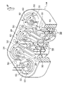
図2に示すように、オイルセパレータ10のケース14は、上下方向から見た形状が平行四辺形状となっており、2列に並んだ第1サイクロン室22、第2サイクロン室24、第3サイクロン室26、第4サイクロン室28、第5サイクロン室30、第6サイクロン室32の6つのサイクロン室を備えている。
アッパキャップ12はケース14の上面を覆っており、アッパキャップ12の上面12Aには、ブローバイガスを導入するガス導入管36と、ブローバイガスを排出するガス排出管38とが取付けられている。なお、ガス導入管36はアッパキャップ12における第1サイクロン室22の上部となる部位に連結されており、ガス排出管38はアッパキャップ12における第6サイクロン室32の上部となる部位に連結されている。
アンダキャップ16はケース14の下面を覆っており、アンダキャップ16は、ブローバイガスから分離されたオイルを回収する2つのオイルドレン40、42を備えている。また、オイルドレン40は、第1サイクロン室22、第2サイクロン室24、第3サイクロン室26の各下部に跨って設けられており、第1サイクロン室22、第2サイクロン室24、第3サイクロン室26においてブローバイガスから分離されたオイルを回収できるようになっている。一方、オイルドレン42は、第4サイクロン室28、第5サイクロン室30、第6サイクロン室32の各下部に跨って設けられており、第4サイクロン室28、第5サイクロン室30、第6サイクロン室32においてブローバイガスから分離されたオイルを回収できるようになっている。なお、オイルドレン40、42の下部には、それぞれバルブ18が収納されたバルブキャップ20が取付けられている。
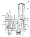
図5及び図6に示すように、各サイクロン室22、24、26、28、30、32は上下分離壁50によって上部と下部に分割されており、各上下分離壁50は上下方向に沿った螺旋形状となっている。
図3及び図4に示すように、第1サイクロン室22の下部は第2サイクロン室24の下部と連結されており(図示無し)、第2サイクロン室24の上部は第3サイクロン室26の上部と連結されている。また、第3サイクロン室26の下部は第4サイクロン室28の下部と連結されており(図示無し)、第4サイクロン室28の上部は第5サイクロン室30の上部と連結されている。さらに、第5サイクロン室30の下部は第6サイクロン室32の下部と連結されている(図示無し)。
より具体的に説明すると、図3及び図4に示すように、第2サイクロン室24の上部は第3サイクロン室26の上部と上連結路52によって連結されている。同様に、第4サイクロン室28の上部は第5サイクロン室30の上部と上連結路52によって連結されている。
一方、第1サイクロン室22の下部は第2サイクロン室24の下部と下連結路56(図7及び図8参照)によって連結されている。同様に、第3サイクロン室26の下部は第4サイクロン室28の下部と下連結路56によって連結されており、第5サイクロン室30の下部は第6サイクロン室32の下部と下連結路56によって連結されている。
図3及び図4に示すように、各サイクロン室22、24、26、28、30、32は、半径方向(幅方向)中間部にそれぞれ周方向に沿って形成された径方向分離壁60を備えており、各サイクロン室22、24、26、28、30、32は径方向分離壁60によって外周部と内周部とに分割されている。
図7に示すように、第1サイクロン室22の上部には、半径方向に沿って衝突壁62が形成されており、衝突壁62の下方側には第1サイクロン室22の上部と下部とを連通する開口部64が形成されている。なお、衝突壁62の径方向内側端部62Aは上方から見て反時計回り方向へ半円状に湾曲されている。
従って、ガス導入管36から第1サイクロン室22の上部に流入したブローバイガス(矢印)は、第1サイクロン室22の内側表面、径方向分離壁60の壁面及び上下分離壁50の上面に沿って反時計回りのサイクロン(旋回流)を形成すると共に一部が衝突壁62によって遮られ、開口部64を通過して、第1サイクロン室22の下部に流入するようになっている。この際、ブローバイガス中のオイルミストが第1サイクロン室22内でのサイクロンの遠心力により凝縮されて油滴となると共に、衝突壁62に当り凝縮されて油滴となるようになっている。また、半円状に湾曲されている衝突壁62の径方向内側端部62Aによって、ブローバイガス中のオイルミストの軌道が長くなり、外周壁に長く当たることで凝縮される油滴の量が多くなるようになっている。
また、第1サイクロン室22の下部に流入したブローバイガス(矢印)は、下連結路56によって第2サイクロン室24の下部に流入するようになっている。この際、ブローバイガス(矢印)の旋回方向が逆方向になると共に、第1サイクロン室22の流路における大径側の外周部が、第2サイクロン室24の流路における小径側の内周部となり、第1サイクロン室22の流路における小径側の内周部が、第2サイクロン室24の流路における大径側の外周部となるようになっている。このため、第1サイクロン室22の外周側を流れる大粒のオイルミストが、第1サイクロン室22の内周側を流れる小粒のオイルミストを巻き込んで捕獲されるようになっている。
図8に示すように、第2サイクロン室24の下部には、第1サイクロン室22の上部と同様に、半径方向に沿って衝突壁62が形成されており、この衝突壁62の上方側には第2サイクロン室24の下部と上部とを連通する開口部64が形成されている。
従って、第2サイクロン室24の下部に流入したブローバイガス(矢印)は、第2サイクロン室24の内側表面、径方向分離壁60の壁面及び上下分離壁50の下面に沿って時計回りのサイクロンを形成すると共に一部が衝突壁62によって遮られ、開口部64を通過して第2サイクロン室24の上部に流入するようになっている。この際、ブローバイガス中のオイルミストが第2サイクロン室24内でのサイクロンの遠心力により凝縮されて油滴となると共に、衝突壁62に当り凝縮されて油滴となるようになっている。また、半円状に湾曲されている衝突壁62の径方向内側端部62Aによって、ブローバイガス中のオイルミストの軌道が長くなり、外周壁に長く当たることで凝縮される油滴の量が多くなるようになっている。
また、第2サイクロン室24の上部に流入したブローバイガス(矢印)は、上連結路52によって第3サイクロン室26の上部に流入するようになっている。この際、ブローバイガス(矢印)の旋回方向が逆方向になると共に、第2サイクロン室24の流路における大径側の外周部が、第3サイクロン室26の流路における小径側の内周部となり、第2サイクロン室24の流路における小径側の内周部が、第3サイクロン室26の流路における大径側の外周部となるようになっている。このため、第2サイクロン室24の外周側を流れる大粒のオイルミストが、第2サイクロン室24の内周側を流れる小粒のオイルミストを巻き込んで捕獲されるようになっている。
なお、第3サイクロン室26、第4サイクロン室28、第5サイクロン室30及び第6サイクロン室32も同様の構成になっており、ブローバイガス(矢印)は、第3サイクロン室26の上部、第3サイクロン室26の下部、第4サイクロン室28の下部、第4サイクロン室28の上部、第5サイクロン室30の上部、第5サイクロン室30の下部、第6サイクロン室32の下部、第6サイクロン室32の上部の順に流れ、ガス排出管38からオイルセパレータ10の外へ排出されるようになっている。
このように、各サイクロン室22、24、26、28、30、32の内部で生じるサイクロンによる遠心力により、オイルミストが凝集されてブローバイガスから分離されると共に、一部が衝突壁62に衝突することにより、オイルミストが凝集されてブローバイガスから分離されるようになっている。また、分離されたオイルは各サイクロン室22、24、26、28、30、32の外周壁や衝突壁62に付着し、その後、各サイクロン室22、24、26、28、30、32の下部に落下して捕集されるようになっている。また、各サイクロン室22、24、26において捕集されたオイルは、オイルドレン40から回収されると共に、各サイクロン室28、30、32において捕集されたオイルは、オイルドレン42から回収されるようになっている。一方、オイルミストが分離されたブローバイガスがガス排出管38から排出されるようになっている。
図5に示すように、オイルセパレータ10内をブローバイガス(矢印)が流れ、オイルセパレータ10内に負圧が発生している状態では、アンダキャップ16のオイルドレン42に設けられたバルブ18が閉じるようになっている。
図6に示すように、オイルセパレータ10内が負圧でなくなると、アンダキャップ16のオイルドレン42に設けられたバルブ18が開くようになっている。従って、オイルセパレータ10の内部に溜まったオイル(図6の矢印A)がオイルドレン42から回収されるようになっている。
(作用・効果)
次に、本実施形態の作用を説明する。
本実施形態のオイルセパレータ10では、図3、図4、図7、図8に示すように、ガス導入管36から第1サイクロン室22の上部に流入したブローバイガス(矢印)は、第1サイクロン室22の内側表面、径方向分離壁60の壁面及び上下分離壁50の上面に沿って反時計回りのサイクロンを形成すると共に、一部が衝突壁62によって遮られ、開口部64を通過して第1サイクロン室22の下部に流入する。
次に、本実施形態の作用を説明する。
本実施形態のオイルセパレータ10では、図3、図4、図7、図8に示すように、ガス導入管36から第1サイクロン室22の上部に流入したブローバイガス(矢印)は、第1サイクロン室22の内側表面、径方向分離壁60の壁面及び上下分離壁50の上面に沿って反時計回りのサイクロンを形成すると共に、一部が衝突壁62によって遮られ、開口部64を通過して第1サイクロン室22の下部に流入する。
この際、ブローバイガス中のオイルミストは第1サイクロン室22内でのサイクロンの遠心力により凝縮されて油滴となる共に衝突壁62に衝突して油滴となり、第1サイクロン室22の外壁の内側や衝突壁62を伝って、あるいは第1サイクロン室22の底部に落下して捕集され、第1サイクロン室22の底からオイルドレン40に集められる。
次に、ブローバイガス(矢印)は、第1サイクロン室22の下部から下連結路56を通り第2サイクロン室24の下部に流入する。この際、第2サイクロン室24内ではブローバイガス(矢印)の旋回方向が逆方向になるため、第1サイクロン室22の外周側を流れる大粒のオイルミストが、第1サイクロン室22の内周側を流れる小粒のオイルミストを巻き込んで捕獲される。さらに、第1サイクロン室22の流路における大径側の外周部が、第2サイクロン室24の流路における小径側の内周部となり、第1サイクロン室22の流路における小径側の内周部が、第2サイクロン室24の流路における大径側の外周部となるため、大粒から小粒までのオイルミストが効率良く捕獲される。
また、第2サイクロン室24の下部に流入したブローバイガス(矢印)は、第2サイクロン室24の内側表面、径方向分離壁60の壁面及び上下分離壁50の下面に沿って時計回りのサイクロンを形成すると共に、開口部を通過して、第2サイクロン室24の上部に流入する。
この際、ブローバイガス中のオイルミストは第2サイクロン室24内でのサイクロンの遠心力により凝縮されて油滴となる共に衝突壁62に衝突して油滴となり、第2サイクロン室24の外壁の内側や衝突壁62を伝って、あるいは第2サイクロン室24の底部に落下して捕集され、第2サイクロン室24の底からオイルドレン40に集められる。
更に、ブローバイガス(矢印)は、第3サイクロン室26の上部、第3サイクロン室26の下部、第4サイクロン室28の下部、第4サイクロン室28の上部、第5サイクロン室30の上部、第5サイクロン室30の下部、第6サイクロン室32の下部、第6サイクロン室32の上部の順に流れ、ブローバイガス中のオイルミストが凝縮されて油滴となった後、ガス排出管38からオイルセパレータ10の外へ排出される。
従って、本実施形態のオイルセパレータ10内では、ブローバイガス中のオイルミストが各サイクロン室22、24、26、28、30、32内でのサイクロンの遠心力により凝縮されて油滴となると共に、各サイクロン室22、24、26、28、30、32の衝突壁62に当り凝縮されて油滴となり、オイルドレン40、42に集められる。この結果、微粒子のオイルミストも確実に捕獲することができ、オイルミストの捕獲性能が向上する。
また、本実施形態のオイルセパレータ10では、ブローバイガスが、ガス流路の上流側のサイクロン室の下部からの下流側のサイクロン室内の上部に流れ込み、上流側のサイクロン室の上部から下流側のサイクロン室内の下部に流れ込む。このため、ブローバイガスのガス流路が複雑なラビリンス構造(迷路)となり、このラビリンス構造内をブローバイガスが通過することで、オイルミストの捕獲性能が向上する。
また、本実施形態のオイルセパレータ10では、各サイクロン室22、24、26、28、30、32内でのオイルミストの旋回方向が交互に逆回転となる。このため、各サイクロン室22、24、26、28、30、32の外周側を流れる大粒のオイルミストが、サイクロン室の内周側を流れる小粒のオイルミストを巻き込んで捕獲される。この結果、オイルミストの捕獲性能が向上する。
また、本実施形態のオイルセパレータ10における各サイクロン室22、24、26、28、30、32は径方向分離壁60によって外周部と内周部とに分割されており、ブローバイガスが、各サイクロン室22、24、26、28、30、32の流路における大径側の外周部と、小径側の内周部とを交互に通過する。このため、大粒から小粒までのオイルミストを効率良く捕獲でき、オイルミストの捕獲性能が向上する。この結果、本実施形態のオイルセパレータ10は、同じオイルミストの捕獲性能のオイルセパレータに対してコンパクトにできる。
また、本実施形態では、各サイクロン室22、24、26、28、30、32内をブローバイガス(矢印)がサイクロンとなってスムーズに流れる。このため、オイルセパレータ10の圧力損失を低減できる。
また、本実施形態のオイルセパレータ10では、各サイクロン室22、24、26、28、30、32を2列に配置し、オイルセパレータ10の上下方向から見た形状を平行四辺形状としたため、小型化でき、狭い空間に配置できる。
また、本実施形態のオイルセパレータ10では、ガス導入管36とガス排出管38とがオイルセパレータ10の同一面であるアッパキャップ12の上面12Aに形成されている。このため、ガス導入口36とガス排出口38とにブローバイガスが通過するガス管を容易に連結できる。
また、本実施形態のオイルセパレータ10では、オイルドレン40で第1サイクロン室22、第2サイクロン室24、第3サイクロン室26においてブローバイガスから分離されたオイルを回収できると共に、オイルドレン42で第4サイクロン室28、第5サイクロン室30、第6サイクロン室32においてブローバイガスから分離されたオイルを回収できる。このため、6つのサイクロン室で回収された各オイルを2つのオイルドレインに集約して排出することができる。この結果、サイクロン室の数に対してオイルドレインの数を少なくできるので、オイルセパレータ10をコンパクトにできる。
(その他の実施形態)
以上に於いては、本発明を特定の実施形態について詳細に説明したが、本発明は上記実施形態に限定されるものではなく、本発明の範囲内にて他の種々の実施形態が可能であることは当業者にとって明らかである。例えば、上記実施形態では、6個のサイクロン室22、24、26、28、30、32を2列に配置したが、これに代えて、例えば、9個のサイクロン室を2、3、4と配列し、平面視で台形状にする等の本発明の思想の範囲で各種の形態とすることが可能である。
以上に於いては、本発明を特定の実施形態について詳細に説明したが、本発明は上記実施形態に限定されるものではなく、本発明の範囲内にて他の種々の実施形態が可能であることは当業者にとって明らかである。例えば、上記実施形態では、6個のサイクロン室22、24、26、28、30、32を2列に配置したが、これに代えて、例えば、9個のサイクロン室を2、3、4と配列し、平面視で台形状にする等の本発明の思想の範囲で各種の形態とすることが可能である。
また、上記実施形態では、各サイクロン室を上流側のサイクロン室の旋回方向に対して下流側のサイクロン室の旋回方向が逆方向となるように連結したが、これに代えて、上流側のサイクロン室の旋回方向と下流側のサイクロン室の旋回方向とが同方向となるように各サイクロン室を連結してもよい。
また、上記実施形態では、各サイクロン室をそれぞれ流路を外周部と内周部とに分割する径方向分離壁60を有する構成としたが、これに代えて、各サイクロン室に径方向分離壁を設けない構成としてもよい。
また、上記実施形態のオイルセパレータ10では、オイルセパレータ10の上面となるアッパキャップ12の上面12Aにガス導入管36とガス排出管38とを設けたが、これに代えて、ガス導入管36とガス排出管38との双方をオイルセパレータ10の下面や側面に設けた構成としてもよいし、ガス導入管36とガス排出管38とをオイルセパレータ10における異なる面に設けてもよい。
また、上記実施形態のオイルセパレータ10では、6つのサイクロン室で回収された各オイルを2つのオイルドレインに集約して排出する構成としたが、オイルドレインは2つ以上のサイクロン室の各下部に跨って設けられていればよい。例えば、2つのサイクロン室で回収された各オイルを1つのオイルドレインに集約して排出する構成としてもよいし、8つのサイクロン室で回収された各オイルを2つのオイルドレインに集約して排出する構成としてもよい。
また、本発明のオイルセパレータは、自動車エンジンのヘッドカバー内部に配置され自動車エンジン内部で発生するブローバイガス中のオイルを分離するセパレータとして適用可能であると共に、自動車エンジン以外の内燃機関について適用可能である。
Claims (6)
- ブローバイガスを導入するガス導入口と、
ブローバイガスを排出するガス排出口と、
前記ガス導入口と前記ガス排出口との間の前記ブローバイガスのガス流路に沿って連結され、前記ブローバイガスの流れをサイクロンとする複数のサイクロン室と、
前記複数のサイクロン室の内部に設けられ、前記ブローバイガスの流れの一部を遮る衝突壁と、
を有するオイルセパレータ。 - 前記複数のサイクロン室は、螺旋形状となった上下分離壁によって上部と下部とに分割され、且つ前記上部と前記下部とが開口部によって連通されており、前記ガス流路の上流側のサイクロン室と下流側のサイクロン室との上部と下部とが交互に連結されている請求項1に記載のオイルセパレータ。
- 前記複数のサイクロン室は、前記ガス流路の上流側のサイクロン室のブローバイガスの旋回方向に対して下流側のサイクロン室のブローバイガスの旋回方向が逆方向となるように連結されている請求項1または請求項2に記載のオイルセパレータ。
- 前記複数のサイクロン室は、前記ガス流路を外周部と内周部とに分割する径方向分離壁を有し、前記ガス流路の上流側のサイクロン室のガス流路の外周部が下流側のサイクロン室のガス流路の内周部に連結され、前記ガス流路の上流側のサイクロン室のガス流路の内周部が下流側のサイクロン室のガス流路の外周部に連結されている請求項1~3の何れか1項に記載のオイルセパレータ。
- 前記ガス導入口と前記ガス排出口とが同一面に形成されている請求項1~4の何れか1項に記載のオイルセパレータ。
- 前記複数のサイクロン室の下部に跨って設けられ、前記複数のサイクロン室で回収されたオイルを集約して排出するためのオイルドレインを有する請求項1~5の何れか1項に記載のオイルセパレータ。
Applications Claiming Priority (2)
| Application Number | Priority Date | Filing Date | Title |
|---|---|---|---|
| JP2010199200A JP2012057496A (ja) | 2010-09-06 | 2010-09-06 | オイルセパレータ |
| JP2010-199200 | 2010-09-06 |
Publications (1)
| Publication Number | Publication Date |
|---|---|
| WO2012032933A1 true WO2012032933A1 (ja) | 2012-03-15 |
Family
ID=45810536
Family Applications (1)
| Application Number | Title | Priority Date | Filing Date |
|---|---|---|---|
| PCT/JP2011/069059 Ceased WO2012032933A1 (ja) | 2010-09-06 | 2011-08-24 | オイルセパレータ |
Country Status (2)
| Country | Link |
|---|---|
| JP (1) | JP2012057496A (ja) |
| WO (1) | WO2012032933A1 (ja) |
Cited By (1)
| Publication number | Priority date | Publication date | Assignee | Title |
|---|---|---|---|---|
| GB2552986A (en) * | 2016-08-17 | 2018-02-21 | Nifco Inc | An oil separating device |
Families Citing this family (2)
| Publication number | Priority date | Publication date | Assignee | Title |
|---|---|---|---|---|
| JP2015137631A (ja) * | 2014-01-24 | 2015-07-30 | アイシン精機株式会社 | ブローバイガス用オイルセパレータ |
| KR20160057114A (ko) | 2014-11-13 | 2016-05-23 | 현대자동차주식회사 | 오일 세퍼레이터 |
Citations (5)
| Publication number | Priority date | Publication date | Assignee | Title |
|---|---|---|---|---|
| JPS60133114U (ja) * | 1984-02-17 | 1985-09-05 | トヨタ自動車株式会社 | ブロ−バイガスのオイル分離装置 |
| JPH02294510A (ja) * | 1989-05-10 | 1990-12-05 | Nippon Soken Inc | 気液分離装置 |
| JPH08319814A (ja) * | 1995-05-26 | 1996-12-03 | Kojima Press Co Ltd | 内燃機関用オイルトラッパ |
| JP2004521238A (ja) * | 2001-06-07 | 2004-07-15 | ローベルト ボツシユ ゲゼルシヤフト ミツト ベシユレンクテル ハフツング | 内燃機関のクランクケーシングガスのための油分離装置 |
| JP2008267582A (ja) * | 2007-04-25 | 2008-11-06 | Toyota Motor Corp | ブリーザ装置 |
-
2010
- 2010-09-06 JP JP2010199200A patent/JP2012057496A/ja active Pending
-
2011
- 2011-08-24 WO PCT/JP2011/069059 patent/WO2012032933A1/ja not_active Ceased
Patent Citations (5)
| Publication number | Priority date | Publication date | Assignee | Title |
|---|---|---|---|---|
| JPS60133114U (ja) * | 1984-02-17 | 1985-09-05 | トヨタ自動車株式会社 | ブロ−バイガスのオイル分離装置 |
| JPH02294510A (ja) * | 1989-05-10 | 1990-12-05 | Nippon Soken Inc | 気液分離装置 |
| JPH08319814A (ja) * | 1995-05-26 | 1996-12-03 | Kojima Press Co Ltd | 内燃機関用オイルトラッパ |
| JP2004521238A (ja) * | 2001-06-07 | 2004-07-15 | ローベルト ボツシユ ゲゼルシヤフト ミツト ベシユレンクテル ハフツング | 内燃機関のクランクケーシングガスのための油分離装置 |
| JP2008267582A (ja) * | 2007-04-25 | 2008-11-06 | Toyota Motor Corp | ブリーザ装置 |
Cited By (3)
| Publication number | Priority date | Publication date | Assignee | Title |
|---|---|---|---|---|
| GB2552986A (en) * | 2016-08-17 | 2018-02-21 | Nifco Inc | An oil separating device |
| CN109642483A (zh) * | 2016-08-17 | 2019-04-16 | 株式会社利富高 | 油分离装置 |
| GB2552986B (en) * | 2016-08-17 | 2020-09-16 | Nifco Inc | A device for separating oil from a blow-by gas |
Also Published As
| Publication number | Publication date |
|---|---|
| JP2012057496A (ja) | 2012-03-22 |
Similar Documents
| Publication | Publication Date | Title |
|---|---|---|
| JP5847445B2 (ja) | 内燃機関のオイルセパレータ | |
| US10729998B2 (en) | Oil mist separator | |
| RU2287978C1 (ru) | Пылеулавливающее устройство со множеством циклонных пылеуловителей | |
| US7159723B2 (en) | Cyclone separator | |
| US20060230722A1 (en) | Multi-cyclone apparatus for vacuum cleaner | |
| JP4510108B2 (ja) | ブローバイガス用オイルセパレータ | |
| CN101506479B (zh) | 用于从气体中分离液体的装置 | |
| JP5290732B2 (ja) | 内燃機関のオイルセパレータ | |
| JP5772402B2 (ja) | オイルセパレータ | |
| JP2009121281A (ja) | 内燃機関のオイルセパレータ | |
| JP2004130311A (ja) | ガス流から液体を分離する装置 | |
| CN102027206A (zh) | 用于内燃机曲轴箱通风的分离器 | |
| WO2012032933A1 (ja) | オイルセパレータ | |
| JP2012012987A (ja) | オイルセパレータ | |
| JP4425951B2 (ja) | ブローバイガス用オイルセパレータ | |
| JPH0676614U (ja) | オイルミストセパレータ | |
| JP2011047306A (ja) | オイルミストセパレータ | |
| JP6537489B2 (ja) | オイルセパレータ | |
| JP6178717B2 (ja) | オイルセパレータ | |
| JP2008121478A (ja) | 内燃機関のブローバイ流路構造 | |
| CN112638498B (zh) | 用于空气/液体分离的交错阵列布置 | |
| JP4890230B2 (ja) | 内燃機関におけるブローバイガス流路のオイルミストセパレータ | |
| JP5017490B1 (ja) | サイクロン式オイルセパレータ | |
| JP5223728B2 (ja) | オイルミストセパレータ | |
| JP6176047B2 (ja) | オイルセパレータ |
Legal Events
| Date | Code | Title | Description |
|---|---|---|---|
| 121 | Ep: the epo has been informed by wipo that ep was designated in this application |
Ref document number: 11823412 Country of ref document: EP Kind code of ref document: A1 |
|
| NENP | Non-entry into the national phase |
Ref country code: DE |
|
| 122 | Ep: pct application non-entry in european phase |
Ref document number: 11823412 Country of ref document: EP Kind code of ref document: A1 |