WO2012029815A1 - プーリ構造体 - Google Patents
プーリ構造体 Download PDFInfo
- Publication number
- WO2012029815A1 WO2012029815A1 PCT/JP2011/069669 JP2011069669W WO2012029815A1 WO 2012029815 A1 WO2012029815 A1 WO 2012029815A1 JP 2011069669 W JP2011069669 W JP 2011069669W WO 2012029815 A1 WO2012029815 A1 WO 2012029815A1
- Authority
- WO
- WIPO (PCT)
- Prior art keywords
- pulley
- coil spring
- friction
- hub structure
- taper ring
- Prior art date
Links
Images


Classifications
-
- F—MECHANICAL ENGINEERING; LIGHTING; HEATING; WEAPONS; BLASTING
- F16—ENGINEERING ELEMENTS AND UNITS; GENERAL MEASURES FOR PRODUCING AND MAINTAINING EFFECTIVE FUNCTIONING OF MACHINES OR INSTALLATIONS; THERMAL INSULATION IN GENERAL
- F16H—GEARING
- F16H55/00—Elements with teeth or friction surfaces for conveying motion; Worms, pulleys or sheaves for gearing mechanisms
- F16H55/32—Friction members
- F16H55/36—Pulleys
-
- F—MECHANICAL ENGINEERING; LIGHTING; HEATING; WEAPONS; BLASTING
- F16—ENGINEERING ELEMENTS AND UNITS; GENERAL MEASURES FOR PRODUCING AND MAINTAINING EFFECTIVE FUNCTIONING OF MACHINES OR INSTALLATIONS; THERMAL INSULATION IN GENERAL
- F16D—COUPLINGS FOR TRANSMITTING ROTATION; CLUTCHES; BRAKES
- F16D3/00—Yielding couplings, i.e. with means permitting movement between the connected parts during the drive
- F16D3/02—Yielding couplings, i.e. with means permitting movement between the connected parts during the drive adapted to specific functions
- F16D3/12—Yielding couplings, i.e. with means permitting movement between the connected parts during the drive adapted to specific functions specially adapted for accumulation of energy to absorb shocks or vibration
-
- F—MECHANICAL ENGINEERING; LIGHTING; HEATING; WEAPONS; BLASTING
- F16—ENGINEERING ELEMENTS AND UNITS; GENERAL MEASURES FOR PRODUCING AND MAINTAINING EFFECTIVE FUNCTIONING OF MACHINES OR INSTALLATIONS; THERMAL INSULATION IN GENERAL
- F16D—COUPLINGS FOR TRANSMITTING ROTATION; CLUTCHES; BRAKES
- F16D7/00—Slip couplings, e.g. slipping on overload, for absorbing shock
- F16D7/02—Slip couplings, e.g. slipping on overload, for absorbing shock of the friction type
- F16D7/024—Slip couplings, e.g. slipping on overload, for absorbing shock of the friction type with axially applied torque limiting friction surfaces
- F16D7/028—Slip couplings, e.g. slipping on overload, for absorbing shock of the friction type with axially applied torque limiting friction surfaces with conical friction surfaces
-
- F—MECHANICAL ENGINEERING; LIGHTING; HEATING; WEAPONS; BLASTING
- F16—ENGINEERING ELEMENTS AND UNITS; GENERAL MEASURES FOR PRODUCING AND MAINTAINING EFFECTIVE FUNCTIONING OF MACHINES OR INSTALLATIONS; THERMAL INSULATION IN GENERAL
- F16F—SPRINGS; SHOCK-ABSORBERS; MEANS FOR DAMPING VIBRATION
- F16F15/00—Suppression of vibrations in systems; Means or arrangements for avoiding or reducing out-of-balance forces, e.g. due to motion
- F16F15/10—Suppression of vibrations in rotating systems by making use of members moving with the system
- F16F15/12—Suppression of vibrations in rotating systems by making use of members moving with the system using elastic members or friction-damping members, e.g. between a rotating shaft and a gyratory mass mounted thereon
- F16F15/121—Suppression of vibrations in rotating systems by making use of members moving with the system using elastic members or friction-damping members, e.g. between a rotating shaft and a gyratory mass mounted thereon using springs as elastic members, e.g. metallic springs
- F16F15/123—Wound springs
-
- F—MECHANICAL ENGINEERING; LIGHTING; HEATING; WEAPONS; BLASTING
- F16—ENGINEERING ELEMENTS AND UNITS; GENERAL MEASURES FOR PRODUCING AND MAINTAINING EFFECTIVE FUNCTIONING OF MACHINES OR INSTALLATIONS; THERMAL INSULATION IN GENERAL
- F16H—GEARING
- F16H55/00—Elements with teeth or friction surfaces for conveying motion; Worms, pulleys or sheaves for gearing mechanisms
- F16H55/32—Friction members
- F16H55/36—Pulleys
- F16H2055/366—Pulleys with means providing resilience or vibration damping
Definitions
- the present invention relates to a pulley structure having a pulley member and a hub structure that can rotate relative to the pulley member.
- a belt transmission mechanism in which a belt is wound around a plurality of pulley structures as a mechanism for transmitting the power of an engine such as an automobile.
- a pulley structure used for such a belt transmission mechanism there are two rotating bodies connected so as to be relatively rotatable, and when a rotational fluctuation occurs in one of the two rotating bodies, the rotational fluctuation
- the thing provided with the structure for attenuating is known (for example, patent document 1).
- Patent Document 1 discloses an annular pulley member, a hub structure (an AC generator shaft is fixed so as not to be relatively rotatable), and an annular pulley member and the hub structure.
- a pulley comprising a coil spring is disclosed. According to this configuration, when a rotational variation occurs in the hub structure, the rotational variation can be attenuated by elastically deforming the coil spring between the hub structure and the annular pulley member.
- the spring clutch structure as described above since the coil spring is manufactured by plastic deformation processing, it is difficult to achieve uniform dimensional accuracy and surface accuracy, and the end portion of the coil spring and the pulley member or hub structure are difficult to achieve. There is a problem that the friction torque generated between the body and the body tends to vary.
- the friction torque generated between the end of the coil spring and the pulley member or hub structure is determined by the material and performance of the coil spring and the pulley member or hub structure. From the viewpoint of securing the strength of the structure, the range of selection of materials and performance is narrowed (design flexibility is lowered), and the friction torque required by the user may not be realized.
- the present invention has been made to solve the above-described problems, and its purpose is to prevent an excessive force from acting on the coil spring to prevent the coil spring itself from being damaged, and to prevent friction.
- An object of the present invention is to provide a pulley structure that can increase the degree of freedom in design by freely changing the friction torque while suppressing variations in torque.
- a pulley structure includes a tubular pulley member around which a belt is wound, and a hub structure provided inside the pulley member so as to be relatively rotatable with respect to the pulley member.
- a coil spring having one end fixed to the hub structure or the pulley member, a taper ring having a conical curved surface with the other end of the coil spring fixed and a rotation axis of the hub structure as a conical axis;
- a conical curved surface of the tapering and the pulley member, or a friction member interposed between the conical curved surface of the tapering and the hub structure, and the coil spring is in the direction of the rotation axis of the hub structure.
- the taper ring, the friction member, and the pulley member, or the taper ring, the friction member, and the hub structure are pressed by the restoring force of the coil spring. It is characterized in that it is.
- the tapered ring is pressed by the restoring force of the coil spring, and the conical curved surface of the pressed tapered ring presses the pulley member or the hub structure through the friction member.
- the cone of the tapering The coil spring can be prevented from being twisted more than a certain amount by sliding relatively on the surface where the curved surface and the friction member are pressed against each other.
- durability of a coil spring can be improved by preventing a coil spring from twisting more than fixed.
- the friction member that generates the friction torque and the tapered ring having the conical curved surface can be processed with high precision by cutting, molding with a mold, or the like, variation in the friction torque can be suppressed.
- the friction member is fixed to the pulley member or the hub structure, and the friction member is relative only to the taper ring. It is characterized by generating a natural slip.
- the friction member when the friction member is fixed to the pulley member or the hub structure, the friction member is caused to slip relative to the taper ring only.
- the value of the friction torque generated between the tapered curved surface and the friction member can be determined only by considering the static friction coefficient value between the friction member and the taper ring.
- the fixing aspect of the coil spring at least one of one end and the other end of the coil spring is the hub. It is an aspect that is locked by a restoring force of the coil spring in a state elastically deformed in a radial direction with at least one of the structure, the pulley member, and the taper ring, and at least one of one end and the other end of the coil spring; A slip occurs when a rotational torque larger than a friction torque generated between at least one of the hub structure, the pulley member, and the taper ring is input.
- the friction torque generated between the conical curved surface of the taper ring and the friction member, at least one of one end and the other end of the coil spring, and at least one of the hub structure, the pulley member, and the taper ring. Friction torque generated between them can be generated.
- the value of the friction torque generated between the coil spring and at least one of the hub structure, the pulley member, and the taper ring and the value of the friction torque generated between the conical surface of the taper ring and the friction member can be freely set.
- the degree of freedom in design can be increased by changing to
- the friction torque generated between the tapered surface of the tapered ring and the friction member, the coil spring, and the hub structure has a different value.
- the friction torque generated between the conical curved surface of the taper ring and the friction member and the friction torque generated between at least one of the coil spring and the hub structure, the pulley member, and the taper ring By setting different values, depending on the magnitude of the rotational torque input from the pulley member or the hub structure, between the conical curved surface of the tapering and the friction member, or the coil spring and the hub structure, the pulley member and the tapering Between at least one of the two can be determined.
- Pulley that can prevent the coil spring itself from being damaged by preventing an excessive force from acting on the coil spring, and can suppress the variation of the friction torque, while increasing the design freedom by freely changing the friction torque.
- a structure can be provided.
- FIG. 3 is an AA cross-sectional view including a rotation shaft of the drive pulley structure shown in FIG. 2.
- FIG. 4 is a detailed view of the drive pulley structure shown in FIG. 3.
- FIG. 6 is a BB cross-sectional view including a rotation shaft of the drive pulley structure shown in FIG. 5.
- FIG. 7 is a detailed view of the drive pulley structure shown in FIG. 6. It is sectional drawing containing the rotating shaft of the drive pulley structure which concerns on 3rd Embodiment.
- FIG. 1 A first embodiment of the present invention will be described.
- the present invention is applied to a drive pulley structure 1 used in a supplementary drive belt system 100 that drives supplementary notes (water pump, alternator, etc.) by torque of an output shaft 101 of an automobile engine. It is an example which applied.
- the drive pulley structure 1 is used to suppress tension fluctuations of the transmission belt 106 due to engine fluctuations.
- FIG. 1 is a schematic configuration diagram of a supplementary drive belt system 100 of the present embodiment.
- a supplementary drive belt system 100 includes a drive pulley structure 1 (pulley structure) connected to an output shaft 101 of an engine (a crankshaft of a reciprocating engine, an eccentric shaft of a rotary engine, etc.)
- Drive shafts (complementary shafts) 102 and 103 connected to various supplementary notes such as a water pump and an alternator, a driven pulley structure 104 attached to the driven shaft 102, and a driven pulley structure 107 attached to the driven shaft 103.
- a drive pulley structure 1 a driven pulley structure 104, and a transmission belt 106 laid across the driven pulley structure 107.
- a V-ribbed belt having a plurality of V-ribs extending in parallel with each other along the belt longitudinal direction is used as the transmission belt 106.
- the transmission belt 106 is driven by the rotation of the drive pulley structure 1. Then, as the transmission belt 106 travels, the driven pulley structure 104 and the driven pulley structure 107 are rotationally driven, respectively, but a water pump, an alternator, etc. connected to the driven shafts 102 and 103 are not shown. Each supplementary note is driven.
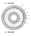
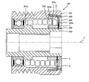
- FIG. 2 is a plan view of the drive pulley structure 1.
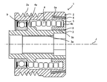
- FIG. 3 is a cross-sectional view taken along the line AA including the rotation axis J of the drive pulley structure 1 shown in FIG.
- FIG. 4 is a detailed view of the drive pulley structure 1 shown in FIG.
- the drive pulley structure 1 includes a cylindrical pulley member 2 around which the transmission belt 106 is wound, and a hub connected to the output shaft 101 and provided inside the pulley member 2.
- the structure 3, the coil spring 4 with one end 4a fixed to the hub structure 3, and the other end 4b of the coil spring 4 are fixed, and the outer periphery has a conical curved surface with the rotation axis J of the hub structure 3 as the conical axis.
- a tapered ring 5 having a surface 5a, and a friction member 6 interposed between the pulley member 2 and the outer peripheral surface 5a having a conically curved surface of the tapered ring 5 are provided.
- the pulley member 2 and the hub structure 3 are connected to each other via a rotary bearing 9 so as to be relatively rotatable. Further, a sliding bearing 8 is interposed between the hub structure 3 and the taper ring 5.
- the pulley member 2 has a cylindrical shape, and a plurality of pulley grooves 2 a extending along the circumferential direction are formed on the outer periphery of the pulley member 2. Then, the plurality of V ribs provided on the inner periphery of the transmission belt 106 are wound around the outer periphery of the pulley member 2 in a state of being engaged with the plurality of pulley grooves 2a.
- the hub structure 3 also has a cylindrical shape, and an output shaft 101 is fitted into the cylinder interior 3a, and the output shaft 101 and the hub structure 3 are connected so as not to be relatively rotatable by appropriate connecting means such as bolts. Is done.
- a material which comprises the pulley member 2 and the hub structure 3 a nonmagnetic material (a paramagnetic body, a diamagnetic body, or an antiferromagnetic body) etc. are mentioned, respectively.
- examples of the nonmagnetic material include an aluminum alloy, a titanium alloy, and a synthetic resin.
- the pulley member 2 and the hub structure 3 are connected to each other via a rotary bearing 9 so as to be relatively rotatable.
- the taper ring 5 has a substantially U-shaped cross section
- the inner peripheral surface 5 b has a cylindrical shape
- the outer peripheral surface 5 a has the rotational axis J of the hub structure 3 as a conical axis. It has a conical curved surface.
- the angle ⁇ formed by the extension line 5 ⁇ / b> L of the outer peripheral surface 5 a having a conical curved surface in a cross-sectional view and the rotation axis J is set in a range of 1 ° or more and less than 90 °.
- a sliding bearing 8 is interposed between the hub structure 3 and the taper ring 5 so that the hub structure 3 and the taper ring 5 can rotate relative to each other.
- the friction member 6 is interposed between the outer peripheral surface 5a having a conical curved surface and the pulley member 2, and the friction member 6 itself is fixed to the pulley member 2 so as not to rotate.
- the friction member 6 is preferably made of a material excellent in wear resistance and compression deformation resistance.
- a metal such as brass, plated brass, bronze, plated bronze, polyamide, polyacetal And synthetic resins such as polyarylate.
- the static friction coefficient between the taper ring 5 and the friction member 6 is set to a value such that the taper ring 5 and the friction member 6 slide relative to each other upon receiving a desired input torque.
- the material of the friction member 6 and the taper ring 5 is selected, the surface processing / shape of the friction member 6 that is in contact with the taper ring 5 (for example, a shape provided with a concavo-convex pattern), or the outer peripheral surface 5a described above.
- the angle ⁇ formed by the extension line 5L and the rotation axis J is set.
- the coil spring 4 As the coil spring 4, a rectangular coil spring in which a linear body having a substantially rectangular cross section is spirally formed as shown in FIG. 3 is used.
- the coil spring 4 is compressed in the direction of the rotation axis J, and has one end 4 a fixed to the hub structure 3 and the other end 4 b fixed to the taper ring 5.
- the tapered ring 5 and the friction member 6 are pressed against each other by the restoring force P of the compressed coil spring 4.
- the tapered ring 5 is pressed by the restoring force P of the coil spring 4, and the outer peripheral surface 5 a having a conical curved surface of the pressed tapered ring 5 presses the pulley member 2 through the friction member 6.
- a friction torque Tf is generated between the outer peripheral surface 5 a having the conical curved surface of the taper ring 5 and the friction member 6, and an input torque T larger than the friction torque Tf is input from the hub structure 3.
- the coil spring 4 can be prevented from twisting more than a certain amount by sliding relatively on the surface where the outer peripheral surface 5a having the conical curved surface of the taper ring 5 and the friction member 6 are in pressure contact with each other.
- durability of the coil spring 4 can be improved by preventing the coil spring 4 from being twisted beyond a certain level.
- the friction member 6 that generates the friction torque Tf and the tapered ring 5 having a conical curved surface can be processed with high precision by cutting, molding with a mold, or the like, variation in the friction torque Tf can be suppressed.
- the desired friction torque Tf can be set by freely changing the material and performance of the friction member 6, and the degree of design freedom can be increased.
- the friction member 6 is fixed to the pulley member 2 in a non-rotatable manner, so that the friction member 6 slips relative to the taper ring 5 only. Accordingly, the value of the friction torque Tf generated between the outer peripheral surface 5a having the conical curved surface of the taper ring 5 and the friction member 6 can be determined only by considering the static friction coefficient value between the friction member 6 and the taper ring 5. I can decide.
- the pulley structure according to the present invention is applied to the drive pulley structure 1 connected to the output shaft 101 of the engine.
- driven shafts each connected to various supplementary notes such as a water pump and an alternator
- the pulley structure according to the present invention may be applied to the driven pulley structures 104 and 107 attached to the supplementary shafts 102 and 103.
- the transmission belt 106 is driven by the rotation of the drive pulley structure 1.
- torque is input from the pulley member 2 side of the driven pulley structure 104 or the driven pulley structure 107 to which the pulley structure according to the present invention is applied.
- the relationship between T and Tf is in the relationship of the above-described equation (3), the contact surface between the outer peripheral surface 5a of the taper ring 5 and the friction member 6 does not slip, and the coil spring 4 does not rotate.
- the input torque T is absorbed by twisting in the direction.
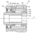
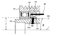
- FIG. 5 is a plan view of the drive pulley structure 201.
- 6 is a BB cross-sectional view including the rotation axis J of the drive pulley structure 201 shown in FIG.
- FIG. 7 is a detailed view of the drive pulley structure 201 shown in FIG.
- the drive pulley structure 201 includes a cylindrical pulley member 202 around which the transmission belt 106 is wound, and a hub connected to the output shaft 101 and provided inside the pulley member 202.
- the structure 203, the coil spring 204 with one end 204b fixed to the pulley member 202, and the other end 204a of the coil spring 204 are fixed, and the inner periphery of the conical curved surface with the rotation axis J of the hub structure 203 as the conical axis
- the taper ring 205 has a surface 205a, and the friction member 206 is interposed between the hub structure 203 and the inner peripheral surface 205a of the taper ring 205 having a conical curved surface.
- the pulley member 202 and the hub structure 203 are connected to each other via a rotary bearing 209 and a sliding bearing 208 so as to be relatively rotatable.
- the taper ring 205 has a substantially cylindrical shape, and its inner peripheral surface 205 a has a conical curved surface shape with the rotation axis J of the hub structure 203 as a conical axis.
- the angle ⁇ formed by the extension line 205 ⁇ / b> L of the inner peripheral surface 205 a having a conical curved surface shape in a cross-sectional view and the rotation axis J is set in a range of 1 ° or more and less than 90 °. .
- the friction member 206 is inserted between the inner peripheral surface 205 a having a conical curved shape and the hub structure 203, and the friction member 206 itself is fixed to the hub structure 203 so as not to rotate.
- the coil spring 204 has one end 204b fixed to the pulley member 202 and the other end 204a fixed to the taper ring 205 while being compressed in the direction of the rotation axis J.
- the tapered ring 205 and the friction member 206 are pressed against each other by the restoring force P of the compressed coil spring 204.
- the taper ring 205 is pressed by the restoring force P of the coil spring. Then, the inner circumferential surface 205a of the tapered ring 205 that has been press-contacted has a conical curved surface shape 205a in the relationship between the angle ⁇ formed by the extension line 205L of the inner circumferential surface 205a of the conical curved surface shape and the rotation axis J in a sectional view.
- the friction member 206 is pressed into contact with the normal force N expressed by the equation (1) described in the first embodiment.
- the inner peripheral surface 205a of the taper ring 205 is formed between the inner peripheral surface 205a of the taper ring 205 and the friction member 206, which is generated when the friction member 206 is pressed into contact with the normal force N shown in Expression (1).
- the friction torque Tf is expressed by the equation (2) described in the first embodiment.
- ⁇ is a coefficient of static friction between the taper ring 205 and the friction member 206
- r is an average radius of the inner peripheral surface 205a having a conical curved shape.
- the taper ring 205 is press-contacted by the restoring force P of the coil spring 204, and the inner peripheral surface 205 a having a conical curved surface of the press-contacted taper ring 205 presses the hub structure 203 through the friction member 206. To do. By doing so, a friction torque Tf is generated between the inner peripheral surface 205 a having a conical curved surface of the taper ring 205 and the friction member 206, and an input torque T larger than the friction torque Tf is input from the hub structure 203.
- the coil spring 204 can be prevented from being twisted more than a certain amount by sliding relatively on the surface where the inner peripheral surface 205a having the conical curved surface of the taper ring 205 and the friction member 206 are in pressure contact with each other.
- the durability of the coil spring 204 can be improved by preventing the coil spring 204 from twisting beyond a certain level.
- the friction member 206 that generates the friction torque Tf and the tapered ring 205 having a conical curved surface can be processed with high precision by cutting, molding with a mold, or the like, and variations in the friction torque Tf can be suppressed. Further, by freely changing the material and performance of the friction member 206, a desired friction torque Tf can be set, and the degree of freedom in design can be increased.
- the friction member 206 is fixed to the hub structure 203 so as not to rotate, so that the friction member 206 is caused to slip relative to the taper ring 205 only. Accordingly, the friction torque Tf generated between the friction member 206 and the inner peripheral surface 205a having the conical curved surface of the taper ring 205 only by considering the static friction coefficient value between the friction member 206 and the taper ring 205 or the like. The value can be determined.
- the driven pulley structure 301 (pulley structure) according to the third embodiment will not be described for the same parts as those of the first embodiment, and will be described focusing on different configurations.
- the driven pulley structure 301 according to the third embodiment has a configuration in which a spring clutch structure is incorporated in the portion of the coil spring 4 of the drive pulley structure 1 described in the first embodiment.
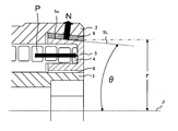
- FIG. 8 is a cross-sectional view including the rotation axis J of the driven pulley structure 301.
- the driven pulley structure 301 does not directly fix the other end 4b to the taper ring 5 like the coil spring 4 of the drive pulley structure 1 mentioned in the first embodiment.
- the other end 304b of the coil spring 304 is elastically deformed in the radially outward direction O, and is fixed to the taper ring 305 by its restoring force F (inward radial direction).
- one end 304 a of the coil spring 304 is fixed to the hub structure 303.
- the torque input to the driven pulley structure 301 from the pulley member 302 side is defined as the input torque T (variable), and the friction torque between the outer peripheral surface 305a of the taper ring 305 and the friction member 306 is defined as Tf.
- T input torque
- Tf friction torque between the outer peripheral surface 305a of the taper ring 305 and the friction member 306
- the coil spring 304 is contracted by contact with the clutch surface 305c of the taper ring 305, the coil spring 304 is twisted in the circumferential direction, and the coil spring 304 does not slip while being held in a state where the pressure contact engagement force with the clutch surface 305c is increased.
- the rotation of the pulley member 302 is transmitted to the hub structure 303. Then, supplementary notes such as a water pump and an alternator connected to the driven shaft 102 attached to the hub structure 303 are driven.
- the coil spring 304 is reduced in diameter by contact with the clutch surface 305c of the taper ring 305, and is pressed against the clutch surface 305c. Although it does not slip while being held in a state where the engagement force is increased, the input torque T is absorbed when the contact surface between the outer peripheral surface 305a of the taper ring 305 and the friction member 306 slips. Thereby, the rotation of the pulley member 302 is not transmitted to the hub structure 303, and the pulley member 302 rotates freely.
- the torque input to the driven pulley structure 301 from the hub structure 303 side is defined as the input torque T (variable), the friction torque between the outer peripheral surface 305a of the taper ring 305 and the friction member 306 is defined as Tf, and the coil spring 304
- T the input torque
- Tf the friction torque between the outer peripheral surface 305a of the taper ring 305 and the friction member 306
- Tf the friction torque between the outer peripheral surface 305a of the taper ring 305 and the friction member 306
- the contact surface between the outer peripheral surface 305a of the taper ring 305 and the friction member 306 does not slip.
- the coil spring 304 does not slide while being held with respect to the clutch surface 305 c, and the rotation of the hub structure 303 is transmitted to the pulley member 302.
- the contact surface between the outer peripheral surface 305a of the taper ring 305 and the friction member 306 does not slip.
- the coil spring 304 expands in diameter, and the pressure contact engagement force with respect to the clutch surface 305c is weakened, slip occurs at the contact portion between the coil spring 304 and the clutch surface 305c, and the rotation of the hub structure 303 is transmitted to the pulley member 302. First, the hub structure 303 rotates freely.
- the relationship between the friction torque Tf between the outer peripheral surface 305a of the taper ring 305 and the friction member 306 and the friction torque Ts at the contact portion between the coil spring 304 and the clutch surface 305c is Ts ⁇ Tf.
- the values of the friction torques Ts and Tf are set to different values, depending on the magnitude of the input torque T, the outer peripheral surface 305a of the taper ring 305 and the friction member It can be determined whether to slide between 306 or between coil spring 304 and clutch surface 305c.
- action works, when the said driven pulley structure 301 is mounted
- the output shaft 101 rotates at the start of engine rotation, and torque is input to the driven pulley structure 301 from the hub structure 303 side via the output shaft 101, and the rotational torque of the hub structure 303 is changed to the pulley member 302. Will exceed the rotational torque.
- the rotational torque of the pulley member 302 exceeds the rotational torque of the hub structure 303 by the inertial driving of the transmission belt 106, so that the driven pulley from the pulley member 302 side. Torque is input to the structure 301.
- the other end 304b of the coil spring 304 is elastically deformed in the radially outward direction O, and is fixed to the taper ring 305 by its restoring force F (inward radial direction).
- F inward radial direction
- the present invention is not limited to this, and the other end 304b of the coil spring 304 may be elastically deformed in the radially inward direction and locked to the taper ring 305 by its restoring force (in the radially outward direction).
- one end 304 a of the coil spring 304 is fixed to the hub structure 303.
- the one end 304a of the coil spring 304 is not fixed to the hub structure 303, and the one end 304a of the coil spring 304 is elastically deformed radially outward in the same manner as the other end 304b of the coil spring 304 and its restoring force ( The hub structure 303 may be engaged with the hub structure 303 in the radial direction).
- the driven pulley structure 301 has a structure in which a spring clutch structure is incorporated in the portion of the coil spring 4 of the drive pulley structure 1 mentioned in the first embodiment.
- a configuration in which a spring clutch structure is incorporated in the coil spring 204 portion of the drive pulley structure 201 mentioned above may be adopted.
- the other end 204a of the coil spring 204 is elastically deformed in the radially outward direction, and is attached to the taper ring 205 by its restoring force (inward radial direction).
- one end 204b of the coil spring 204 may be fixed to the pulley member 202, and like the other end 204a of the coil spring 204, the one end 204b is elastically deformed in the radially outward (inward) direction to restore its restoring force (
- the pulley member 202 may be engaged with the pulley member in the radial (outer) direction).
- the friction torque Ts generated during In this way for example, when the driven pulley structure 301 according to the present invention is mounted on the driven shaft 102 and used as the driven pulley structure, when there is an input torque T from the pulley member 302 side, the input torque When T is larger than the friction torque Tf generated between the outer peripheral surface 305a of the taper ring 305 and the friction member 306, the contact surface between the outer peripheral surface 305a of the taper ring 305 and the friction member 306 is slid.
- the input torque T can be absorbed.
- the contact surface between the outer peripheral surface 305a of the taper ring 305 and the friction member 306 does not slip if the relationship with each friction torque is Ts ⁇ T ⁇ Tf.
- the coil spring 304 slips at the contact portion with the clutch surface 305c, and the rotation of the hub structure 303 is not transmitted to the pulley member 302, so that the hub structure 303 can be freely rotated.
- the relationship between the frictional torques is Ts ⁇ Tf ⁇ T
- the coil spring 304 slips at the contact portion with the clutch surface 305c, and the rotation of the hub structure 303 is not transmitted to the pulley member 302.
- the structure 303 can be freely rotated. As a result, the friction torque Ts generated between the other end 304b of the coil spring 304 and the clutch surface 305c of the taper ring 305, and between the outer peripheral surface 305a having a conical curved surface of the taper ring 305 and the friction member 306 are generated.
- the degree of freedom in design can be increased by freely changing the value of the friction torque Tf.
- the outer peripheral surface 305a of the taper ring 305 and the friction member depending on the magnitude of the input torque T It can be determined whether to slide between 306 or between coil spring 304 and clutch surface 305c.
Landscapes
- Engineering & Computer Science (AREA)
- General Engineering & Computer Science (AREA)
- Mechanical Engineering (AREA)
- Physics & Mathematics (AREA)
- Acoustics & Sound (AREA)
- Aviation & Aerospace Engineering (AREA)
- Pulleys (AREA)
- One-Way And Automatic Clutches, And Combinations Of Different Clutches (AREA)
- Devices For Conveying Motion By Means Of Endless Flexible Members (AREA)
Abstract
Description
本発明の第1実施形態について説明する。本実施形態は、図1に示すように、自動車用エンジンの出力軸101のトルクによって補記(ウォーターポンプやオルタネータ等)を駆動する、補記駆動ベルトシステム100に用いられる駆動プーリ構造体1に本発明を適用した一例である。なお、駆動プーリ構造体1は、エンジンの回転変動に起因する伝動ベルト106の張力変動を抑制するために使用される。
図1は本実施形態の補記駆動ベルトシステム100の概略構成図である。図1に示すように、補記駆動ベルトシステム100は、エンジンの出力軸101(レシプロエンジンのクランクシャフトや、ロータリーエンジンのエキセントリックシャフト等)に連結された駆動プーリ構造体1(プーリ構造体)と、ウォーターポンプやオルタネータ等の各種補記にそれぞれ連結された従動軸(補記軸)102、103と、従動軸102に取り付けられた従動プーリ構造体104と、従動軸103に取り付けられた従動プーリ構造体107と、駆動プーリ構造体1、従動プーリ構造体104、及び、従動プーリ構造体107にわたって架け渡された伝動ベルト106とを有する。尚、本実施形態では、伝動ベルト106として、ベルト長手方向に沿って互いに平行に延びる複数のVリブを有するVリブドベルトが用いられている。
次に、出力軸101のトルクによって回転駆動される駆動プーリ構造体1について詳細に説明する。図2は駆動プーリ構造体1の平面図である。また、図3は、図2に示した駆動プーリ構造体1の回転軸Jを含むA-A断面図である。また、図4は、図3に示した駆動プーリ構造体1の詳細図である。
N=P/sinθ・・・(1)
Tf=μ×N×r=μ×P/sinθ×r・・・(2)
μ:テーパリング5と摩擦部材6との間の静止摩擦係数
r:円錐曲面をした外周面5aの平均半径
次に、本実施形態の駆動プーリ構造体1の作用について説明する。ここでは、エンジンの回転開始時に出力軸101が回転して、出力軸101を介してハブ構造体3側から駆動プーリ構造体1にトルクが入力された場合を想定して説明する。出力軸101を介してハブ構造体3側から入力されたトルクを入力トルクT(変数)とすると、TとTfとの関係が次式(3)の関係にある場合、テーパリング5の外周面5aと摩擦部材6との当接面は滑らず、コイルばね4が周方向にねじれることにより入力トルクTを吸収する。
T<Tf・・・(3)
一方、TとTfとの関係が次式(4)の関係にある場合、コイルばね4は周方向にねじれずに、テーパリング5の外周面5aと摩擦部材6との当接面が滑ることにより入力トルクTを吸収する。
T>Tf・・・(4)
次に、第2実施形態に係る駆動プーリ構造体201について、第1実施形態と同様の箇所は説明を省略し、相違する構成を中心に説明する。図5は駆動プーリ構造体201の平面図である。また、図6は、図5に示した駆動プーリ構造体201の回転軸Jを含むBB断面図である。また、図7は、図6に示した駆動プーリ構造体201の詳細図である。
図5及び図6に示すように、駆動プーリ構造体201は、伝動ベルト106が巻き掛けられる円筒形状のプーリ部材202と、出力軸101に連結されるとともにプーリ部材202の内側に設けられたハブ構造体203と、一端204bがプーリ部材202に固定されたコイルばね204と、コイルばね204の他端204aが固定され、ハブ構造体203の回転軸Jを円錐軸とした円錐曲面状の内周面205aを有するテーパリング205と、テーパリング205の円錐曲面をした内周面205aとハブ構造体203との間に介挿された摩擦部材206とを有している。また、プーリ部材202とハブ構造体203とは回転軸受209及び滑り軸受208を介して相対回転可能に連結されている。
次に、本実施形態の駆動プーリ構造体201の作用について説明する。ここでは、エンジンの回転開始時に出力軸101が回転して、出力軸101を介してハブ構造体203側から駆動プーリ構造体201にトルクが入力された場合を想定して説明する。出力軸101を介してハブ構造体203側から入力されたトルクを入力トルクT(変数)とすると、TとTfとの関係が前述した式(3)の関係(T<Tf)にある場合、テーパリング205の内周面205aと摩擦部材206との当接面は滑らず、コイルばね204が周方向にねじれることにより入力トルクTを吸収する。一方、TとTfとの関係が前述した式(4)の関係(T>Tf)にある場合、コイルばね204は周方向にねじれずに、テーパリング205の内周面205aと摩擦部材206との当接面が滑ることにより入力トルクTを吸収する。
次に、第3実施形態に係る従動プーリ構造体301(プーリ構造体)について、第1実施形態と同様の箇所は説明を省略し、相違する構成を中心に説明する。第3実施形態に係る従動プーリ構造体301は、図8に示すように、第1実施形態に挙げた駆動プーリ構造体1のコイルばね4の部分にスプリングクラッチ構造を取り入れた構成としている。そして、第3実施形態では、本発明に係る従動プーリ構造体301を図1の補記駆動ベルトシステム100の従動軸102に装着して、従動プーリ構造体として使用した場合について説明する。なお、図8は、従動プーリ構造体301の回転軸Jを含む断面図である。
第3実施形態に係る従動プーリ構造体301は、第1実施形態で挙げた駆動プーリ構造体1のコイルばね4のように、他端4bをテーパリング5に直接固定するのではなく、図8に示すように、コイルばね304の他端304bを径外方向Oに弾性変形させてその復元力F(径内方向)によりテーパリング305に係止させて装着させる構造をしている。一方、コイルばね304の一端304aは、ハブ構造体303に固定されている。
次に、本実施形態の従動プーリ構造体301の作用について説明する。まず、エンジンの回転開始時において、出力軸101が回転して、出力軸101のトルクによって駆動プーリ構造体1及び伝動ベルト106を介して、従動プーリ構造体301のプーリ部材302側から従動プーリ構造体301にトルクが入力された場合について説明する。これは、エンジンの回転開始時において、従動プーリ構造体301のプーリ部材302の回転トルクがハブ構造体303の回転トルクを上回る場合を想定している。
本出願は、2010年8月31日出願の日本特許出願(特願2010-193935)に基づくものであり、その内容はここに参照として取り込まれる。
2、202、302: プーリ部材
3、203、303: ハブ構造体
4、204、304: コイルばね
5、205、305: テーパリング
6、206、306: 摩擦部材
100: 補記駆動ベルトシステム
101: 出力軸
104、107、301: 従動プーリ構造体
106: 伝動ベルト
J: 回転軸
Claims (4)
- ベルトが巻き掛けられる筒状のプーリ部材と、
前記プーリ部材の内側において、前記プーリ部材に対して相対回転可能に設けられたハブ構造体と、
一端が前記ハブ構造体又は前記プーリ部材に固定されたコイルばねと、
前記コイルばねの他端が固定され、前記ハブ構造体の回転軸を円錐軸とした円錐曲面を有するテーパリングと、
前記テーパリングの円錐曲面と前記プーリ部材、又は、前記テーパリングの円錐曲面と前記ハブ構造体との間に介挿された摩擦部材と
を有し、
前記コイルばねは前記ハブ構造体の回転軸方向に圧縮されて介挿され、前記コイルばねの復元力によって前記テーパリングと前記摩擦部材と前記プーリ部材、又は、前記テーパリングと前記摩擦部材と前記ハブ構造体とが圧接されていることを特徴とするプーリ構造体。 - 前記摩擦部材は、前記プーリ部材又は前記ハブ構造体に固定され、当該摩擦部材は前記テーパリングとのみ相対的な滑りを発生することを特徴とする請求項1に記載のプーリ構造体。
- 前記コイルばねの固定態様としては、前記コイルばねの一端及び他端の少なくとも1つが、前記ハブ構造体、前記プーリ部材及び前記テーパリングの少なくとも1つと径方向に弾性変形した状態で当該コイルばねの復元力により係止される態様であり、
前記コイルばねの一端及び他端の少なくとも1つと、前記ハブ構造体、前記プーリ部材及び前記テーパリングの少なくとも1つとの間に発生する摩擦トルクよりも大きな回転トルクの入力がなされた場合に滑りが発生することを特徴とする請求項1に記載のプーリ構造体。 - 前記テーパリングの円錐曲面と前記摩擦部材との間に発生する摩擦トルクと、前記コイルばねと前記ハブ構造体、前記プーリ部材及び前記テーパリングの少なくとも1つとの間に発生する摩擦トルクとが異なる値になるようにしたことを特徴とする請求項3に記載のプーリ構造体。
Priority Applications (5)
| Application Number | Priority Date | Filing Date | Title |
|---|---|---|---|
| US13/817,967 US9638308B2 (en) | 2010-08-31 | 2011-08-30 | Pulley structure |
| EP11821830.4A EP2626595B1 (en) | 2010-08-31 | 2011-08-30 | Pulley structure |
| CA2808060A CA2808060C (en) | 2010-08-31 | 2011-08-30 | Pulley structure |
| BR112013004876-0A BR112013004876B1 (pt) | 2010-08-31 | 2011-08-30 | Estrutura de polia |
| CN201180042045.XA CN103080608B (zh) | 2010-08-31 | 2011-08-30 | 皮带轮结构 |
Applications Claiming Priority (2)
| Application Number | Priority Date | Filing Date | Title |
|---|---|---|---|
| JP2010-193935 | 2010-08-31 | ||
| JP2010193935A JP5515084B2 (ja) | 2010-08-31 | 2010-08-31 | プーリ構造体 |
Publications (1)
| Publication Number | Publication Date |
|---|---|
| WO2012029815A1 true WO2012029815A1 (ja) | 2012-03-08 |
Family
ID=45772895
Family Applications (1)
| Application Number | Title | Priority Date | Filing Date |
|---|---|---|---|
| PCT/JP2011/069669 WO2012029815A1 (ja) | 2010-08-31 | 2011-08-30 | プーリ構造体 |
Country Status (7)
| Country | Link |
|---|---|
| US (1) | US9638308B2 (ja) |
| EP (1) | EP2626595B1 (ja) |
| JP (1) | JP5515084B2 (ja) |
| CN (1) | CN103080608B (ja) |
| BR (1) | BR112013004876B1 (ja) |
| CA (1) | CA2808060C (ja) |
| WO (1) | WO2012029815A1 (ja) |
Families Citing this family (21)
| Publication number | Priority date | Publication date | Assignee | Title |
|---|---|---|---|---|
| US8784244B2 (en) * | 2008-04-30 | 2014-07-22 | Dayco Ip Holdings, Llc | Pulley with asymmetric torque-sensitive clutching |
| US8888622B2 (en) * | 2012-06-04 | 2014-11-18 | The Gates Corporation | Isolator decoupler |
| CN102758860B (zh) * | 2012-07-27 | 2015-04-15 | 重庆大易用机械有限公司 | 锥形面摩擦式超越离合器 |
| BR102012022803B1 (pt) * | 2012-09-10 | 2017-05-02 | Zen S/A Indústria Metalúrgica | desacoplador com sistema de roda livre e amortecimento de vibrações |
| US11236812B2 (en) * | 2012-09-10 | 2022-02-01 | Zen S/A Industria Metalurgica | Decoupler with one-way clutch and fail-safe system |
| KR101500138B1 (ko) * | 2013-09-10 | 2015-03-06 | 현대자동차주식회사 | 크랭크 풀리 디커플링 장치 |
| KR102258318B1 (ko) | 2013-10-01 | 2021-06-01 | 리텐스 오토모티브 파트너쉽 | 제어식 댐핑부를 갖는 디커플러 |
| US9169914B2 (en) * | 2014-03-07 | 2015-10-27 | Gates Corporation | Isolating decoupler |
| US9341254B2 (en) | 2014-08-08 | 2016-05-17 | Gates Corporation | Isolating pulley |
| US9759274B2 (en) | 2014-08-18 | 2017-09-12 | Gates Corporation | Accessory tuning device with spring lock |
| JP6871851B2 (ja) | 2014-09-10 | 2021-05-19 | リテンズ オートモーティヴ パートナーシップ | 捩りバネ力を使用する比例減衰式動力伝達デバイス |
| US9291253B1 (en) * | 2015-03-24 | 2016-03-22 | Gates Corporation | Isolating decoupler |
| US9784357B2 (en) * | 2015-04-27 | 2017-10-10 | Ningbo Yangtong Automobile Parts Co., Ltd. | Overrunning alternator damping pulley |
| KR101724471B1 (ko) * | 2015-05-26 | 2017-04-18 | 현대자동차 주식회사 | 진동 저감 댐퍼를 갖는 알터네이터 유닛 |
| US9618099B2 (en) | 2015-07-13 | 2017-04-11 | Gates Corporation | Tensioner with secondary damping |
| CN105715757A (zh) * | 2016-04-12 | 2016-06-29 | 无锡凯能光伏设备有限公司 | 一种带安全离合器可调节式回转驱动装置 |
| JP6511085B2 (ja) * | 2016-04-28 | 2019-05-15 | 三ツ星ベルト株式会社 | プーリ構造体 |
| FR3053394B1 (fr) * | 2016-06-30 | 2019-08-09 | Hutchinson | Poulie de decouplage a embrayage deporte |
| CN110462239B (zh) | 2017-03-28 | 2022-05-10 | 利滕斯汽车合伙公司 | 在弹簧止挡部与阻尼构件之间具有选定的角度的隔离装置 |
| JP6950954B2 (ja) * | 2017-12-22 | 2021-10-13 | 国立大学法人金沢大学 | 液体充填方法、sicm用プローブの製造方法、sicm用プローブ及びsicm |
| US11549558B2 (en) | 2018-08-01 | 2023-01-10 | Gates Corporation | Isolator decoupler |
Citations (6)
| Publication number | Priority date | Publication date | Assignee | Title |
|---|---|---|---|---|
| DE10012233A1 (de) * | 2000-03-14 | 2001-09-20 | Schaeffler Waelzlager Ohg | Riemenscheibe |
| JP3268007B2 (ja) | 1991-06-05 | 2002-03-25 | テスマ インターナショナル インコーポレイティド | 自動車のための蛇行ベルト駆動機構および交流発電機組立体 |
| JP2003322174A (ja) | 2002-05-07 | 2003-11-14 | Ntn Corp | スプリングクラッチ |
| JP2006038183A (ja) * | 2004-07-30 | 2006-02-09 | Koyo Seiko Co Ltd | 動力伝達装置 |
| JP2007113634A (ja) * | 2004-12-02 | 2007-05-10 | Mitsuboshi Belting Ltd | プーリ構造体 |
| JP2008180261A (ja) * | 2007-01-24 | 2008-08-07 | Jtekt Corp | プーリユニット |
Family Cites Families (5)
| Publication number | Priority date | Publication date | Assignee | Title |
|---|---|---|---|---|
| JP4013384B2 (ja) * | 1999-02-05 | 2007-11-28 | 株式会社ジェイテクト | 一方向クラッチ付きプーリユニット |
| KR101153636B1 (ko) * | 2003-12-09 | 2012-06-18 | 리텐스 오토모티브 파트너쉽 | 오버러닝 교류 발전기 디커플러용 스프링 활주 리미터 |
| US7766774B2 (en) * | 2005-02-03 | 2010-08-03 | Litens Automotive Partnership | Torque limited decoupler |
| EP1754914A1 (en) * | 2005-08-19 | 2007-02-21 | Industrias Cántabras de Torneado S.R.L. | Alternator pulley |
| US8529387B2 (en) | 2008-04-30 | 2013-09-10 | Dayco Ip Holdings, Llc | Pulley with asymmetric torque-sensitive clutching |
-
2010
- 2010-08-31 JP JP2010193935A patent/JP5515084B2/ja active Active
-
2011
- 2011-08-30 EP EP11821830.4A patent/EP2626595B1/en active Active
- 2011-08-30 CA CA2808060A patent/CA2808060C/en active Active
- 2011-08-30 BR BR112013004876-0A patent/BR112013004876B1/pt active IP Right Grant
- 2011-08-30 US US13/817,967 patent/US9638308B2/en active Active
- 2011-08-30 CN CN201180042045.XA patent/CN103080608B/zh active Active
- 2011-08-30 WO PCT/JP2011/069669 patent/WO2012029815A1/ja active Application Filing
Patent Citations (6)
| Publication number | Priority date | Publication date | Assignee | Title |
|---|---|---|---|---|
| JP3268007B2 (ja) | 1991-06-05 | 2002-03-25 | テスマ インターナショナル インコーポレイティド | 自動車のための蛇行ベルト駆動機構および交流発電機組立体 |
| DE10012233A1 (de) * | 2000-03-14 | 2001-09-20 | Schaeffler Waelzlager Ohg | Riemenscheibe |
| JP2003322174A (ja) | 2002-05-07 | 2003-11-14 | Ntn Corp | スプリングクラッチ |
| JP2006038183A (ja) * | 2004-07-30 | 2006-02-09 | Koyo Seiko Co Ltd | 動力伝達装置 |
| JP2007113634A (ja) * | 2004-12-02 | 2007-05-10 | Mitsuboshi Belting Ltd | プーリ構造体 |
| JP2008180261A (ja) * | 2007-01-24 | 2008-08-07 | Jtekt Corp | プーリユニット |
Also Published As
| Publication number | Publication date |
|---|---|
| EP2626595A4 (en) | 2014-02-26 |
| US9638308B2 (en) | 2017-05-02 |
| US20130150191A1 (en) | 2013-06-13 |
| CA2808060A1 (en) | 2012-03-08 |
| EP2626595A1 (en) | 2013-08-14 |
| BR112013004876B1 (pt) | 2020-09-29 |
| EP2626595B1 (en) | 2019-08-07 |
| CN103080608A (zh) | 2013-05-01 |
| CA2808060C (en) | 2018-05-22 |
| BR112013004876A2 (pt) | 2016-05-03 |
| JP5515084B2 (ja) | 2014-06-11 |
| CN103080608B (zh) | 2016-01-20 |
| JP2012052576A (ja) | 2012-03-15 |
Similar Documents
| Publication | Publication Date | Title |
|---|---|---|
| JP5515084B2 (ja) | プーリ構造体 | |
| JP6871851B2 (ja) | 捩りバネ力を使用する比例減衰式動力伝達デバイス | |
| JP5008928B2 (ja) | プーリ構造体 | |
| JP2017503984A (ja) | アイソレーティング・デカップラ | |
| KR20130108516A (ko) | 오버러닝 및 진동 감쇠 능력을 갖는 격리 풀리 | |
| JP2012506975A (ja) | トルクリミッタ付きオーバーランニングデカップラ | |
| WO2010147220A1 (ja) | 動力伝達機構 | |
| JP2006177548A (ja) | 動力伝達部材用のプーリー、そのようなプーリーが装着された別個のスタータオルタネータ、およびエンジン駆動装置 | |
| EP2527681A2 (en) | Torque fluctuation absorbing apparatus | |
| JP2015025483A (ja) | 一方向クラッチ内蔵型プーリ装置 | |
| KR20140035347A (ko) | 댐핑 스프링을 구비한 마찰 클러치 플레이트 | |
| CN109312789A (zh) | 皮带轮解耦器 | |
| JP6511085B2 (ja) | プーリ構造体 | |
| JP6490479B2 (ja) | 車両用オルタネータダンパプーリ | |
| US11326648B2 (en) | Belt pulley decoupler | |
| US11708886B2 (en) | Single spring, torsionally compliant, overrunning decoupler | |
| JP5800131B2 (ja) | トルク変動吸収ダンパ | |
| JP6747963B2 (ja) | プーリ構造体 | |
| JP4743391B2 (ja) | トルク変動吸収ダンパ | |
| JP4352926B2 (ja) | 動力伝達装置 | |
| JP5257617B2 (ja) | トルク変動吸収ダンパ | |
| JP2008019979A (ja) | 伝動ベルトの多軸駆動装置 | |
| JP2014084996A (ja) | 回転変動吸収ダンパプーリ | |
| JP5507608B2 (ja) | プーリ構造体 | |
| JP2008144827A (ja) | ダンパ付プーリ |
Legal Events
| Date | Code | Title | Description |
|---|---|---|---|
| WWE | Wipo information: entry into national phase |
Ref document number: 201180042045.X Country of ref document: CN |
|
| 121 | Ep: the epo has been informed by wipo that ep was designated in this application |
Ref document number: 11821830 Country of ref document: EP Kind code of ref document: A1 |
|
| ENP | Entry into the national phase |
Ref document number: 2808060 Country of ref document: CA |
|
| WWE | Wipo information: entry into national phase |
Ref document number: 13817967 Country of ref document: US |
|
| WWE | Wipo information: entry into national phase |
Ref document number: 2011821830 Country of ref document: EP |
|
| NENP | Non-entry into the national phase |
Ref country code: DE |
|
| REG | Reference to national code |
Ref country code: BR Ref legal event code: B01A Ref document number: 112013004876 Country of ref document: BR |
|
| ENP | Entry into the national phase |
Ref document number: 112013004876 Country of ref document: BR Kind code of ref document: A2 Effective date: 20130228 |