EP2626595B1 - Pulley structure - Google Patents
Pulley structure Download PDFInfo
- Publication number
- EP2626595B1 EP2626595B1 EP11821830.4A EP11821830A EP2626595B1 EP 2626595 B1 EP2626595 B1 EP 2626595B1 EP 11821830 A EP11821830 A EP 11821830A EP 2626595 B1 EP2626595 B1 EP 2626595B1
- Authority
- EP
- European Patent Office
- Prior art keywords
- tapering
- frictional
- coil spring
- pulley
- hub structure
- Prior art date
- Legal status (The legal status is an assumption and is not a legal conclusion. Google has not performed a legal analysis and makes no representation as to the accuracy of the status listed.)
- Not-in-force
Links
- 230000005540 biological transmission Effects 0.000 description 18
- 238000010276 construction Methods 0.000 description 8
- 239000000463 material Substances 0.000 description 8
- 230000003068 static effect Effects 0.000 description 7
- 238000010586 diagram Methods 0.000 description 6
- XLYOFNOQVPJJNP-UHFFFAOYSA-N water Substances O XLYOFNOQVPJJNP-UHFFFAOYSA-N 0.000 description 5
- 238000000465 moulding Methods 0.000 description 3
- 238000005096 rolling process Methods 0.000 description 3
- 229910001369 Brass Inorganic materials 0.000 description 2
- 229910000906 Bronze Inorganic materials 0.000 description 2
- 239000010951 brass Substances 0.000 description 2
- 239000010974 bronze Substances 0.000 description 2
- KUNSUQLRTQLHQQ-UHFFFAOYSA-N copper tin Chemical compound [Cu].[Sn] KUNSUQLRTQLHQQ-UHFFFAOYSA-N 0.000 description 2
- 230000000694 effects Effects 0.000 description 2
- 239000000696 magnetic material Substances 0.000 description 2
- 238000000034 method Methods 0.000 description 2
- 229920003002 synthetic resin Polymers 0.000 description 2
- 239000000057 synthetic resin Substances 0.000 description 2
- 229910000838 Al alloy Inorganic materials 0.000 description 1
- 229930182556 Polyacetal Natural products 0.000 description 1
- 239000004952 Polyamide Substances 0.000 description 1
- 229910001069 Ti alloy Inorganic materials 0.000 description 1
- 230000002159 abnormal effect Effects 0.000 description 1
- 239000002885 antiferromagnetic material Substances 0.000 description 1
- -1 brass Chemical class 0.000 description 1
- 230000006835 compression Effects 0.000 description 1
- 238000007906 compression Methods 0.000 description 1
- 238000013016 damping Methods 0.000 description 1
- 230000003247 decreasing effect Effects 0.000 description 1
- 239000002889 diamagnetic material Substances 0.000 description 1
- 238000006073 displacement reaction Methods 0.000 description 1
- 239000002184 metal Substances 0.000 description 1
- 229910052751 metal Inorganic materials 0.000 description 1
- 150000002739 metals Chemical class 0.000 description 1
- 239000002907 paramagnetic material Substances 0.000 description 1
- 239000004033 plastic Substances 0.000 description 1
- 229920002647 polyamide Polymers 0.000 description 1
- 229920001230 polyarylate Polymers 0.000 description 1
- 229920006324 polyoxymethylene Polymers 0.000 description 1
Images


Classifications
-
- F—MECHANICAL ENGINEERING; LIGHTING; HEATING; WEAPONS; BLASTING
- F16—ENGINEERING ELEMENTS AND UNITS; GENERAL MEASURES FOR PRODUCING AND MAINTAINING EFFECTIVE FUNCTIONING OF MACHINES OR INSTALLATIONS; THERMAL INSULATION IN GENERAL
- F16H—GEARING
- F16H55/00—Elements with teeth or friction surfaces for conveying motion; Worms, pulleys or sheaves for gearing mechanisms
- F16H55/32—Friction members
- F16H55/36—Pulleys
-
- F—MECHANICAL ENGINEERING; LIGHTING; HEATING; WEAPONS; BLASTING
- F16—ENGINEERING ELEMENTS AND UNITS; GENERAL MEASURES FOR PRODUCING AND MAINTAINING EFFECTIVE FUNCTIONING OF MACHINES OR INSTALLATIONS; THERMAL INSULATION IN GENERAL
- F16D—COUPLINGS FOR TRANSMITTING ROTATION; CLUTCHES; BRAKES
- F16D3/00—Yielding couplings, i.e. with means permitting movement between the connected parts during the drive
- F16D3/02—Yielding couplings, i.e. with means permitting movement between the connected parts during the drive adapted to specific functions
- F16D3/12—Yielding couplings, i.e. with means permitting movement between the connected parts during the drive adapted to specific functions specially adapted for accumulation of energy to absorb shocks or vibration
-
- F—MECHANICAL ENGINEERING; LIGHTING; HEATING; WEAPONS; BLASTING
- F16—ENGINEERING ELEMENTS AND UNITS; GENERAL MEASURES FOR PRODUCING AND MAINTAINING EFFECTIVE FUNCTIONING OF MACHINES OR INSTALLATIONS; THERMAL INSULATION IN GENERAL
- F16D—COUPLINGS FOR TRANSMITTING ROTATION; CLUTCHES; BRAKES
- F16D7/00—Slip couplings, e.g. slipping on overload, for absorbing shock
- F16D7/02—Slip couplings, e.g. slipping on overload, for absorbing shock of the friction type
- F16D7/024—Slip couplings, e.g. slipping on overload, for absorbing shock of the friction type with axially applied torque limiting friction surfaces
- F16D7/028—Slip couplings, e.g. slipping on overload, for absorbing shock of the friction type with axially applied torque limiting friction surfaces with conical friction surfaces
-
- F—MECHANICAL ENGINEERING; LIGHTING; HEATING; WEAPONS; BLASTING
- F16—ENGINEERING ELEMENTS AND UNITS; GENERAL MEASURES FOR PRODUCING AND MAINTAINING EFFECTIVE FUNCTIONING OF MACHINES OR INSTALLATIONS; THERMAL INSULATION IN GENERAL
- F16F—SPRINGS; SHOCK-ABSORBERS; MEANS FOR DAMPING VIBRATION
- F16F15/00—Suppression of vibrations in systems; Means or arrangements for avoiding or reducing out-of-balance forces, e.g. due to motion
- F16F15/10—Suppression of vibrations in rotating systems by making use of members moving with the system
- F16F15/12—Suppression of vibrations in rotating systems by making use of members moving with the system using elastic members or friction-damping members, e.g. between a rotating shaft and a gyratory mass mounted thereon
- F16F15/121—Suppression of vibrations in rotating systems by making use of members moving with the system using elastic members or friction-damping members, e.g. between a rotating shaft and a gyratory mass mounted thereon using springs as elastic members, e.g. metallic springs
- F16F15/123—Wound springs
-
- F—MECHANICAL ENGINEERING; LIGHTING; HEATING; WEAPONS; BLASTING
- F16—ENGINEERING ELEMENTS AND UNITS; GENERAL MEASURES FOR PRODUCING AND MAINTAINING EFFECTIVE FUNCTIONING OF MACHINES OR INSTALLATIONS; THERMAL INSULATION IN GENERAL
- F16H—GEARING
- F16H55/00—Elements with teeth or friction surfaces for conveying motion; Worms, pulleys or sheaves for gearing mechanisms
- F16H55/32—Friction members
- F16H55/36—Pulleys
- F16H2055/366—Pulleys with means providing resilience or vibration damping
Definitions
- the present invention relates to a pulley structure having a pulley member and a hub structure that can rotate relative to the pulley member.
- a transmission mechanism for transmitting the power of an engine of a motor vehicle there is a belt transmission mechanism in which a belt is looped between pulleys.
- a pulley structure that is used in such a belt transmission mechanism there is known a pulley structure having a configuration for damping a change in rotation when the change in rotation is generated in one of two rotational members (for example, Japanese Patent 3268007 ).
- this Japanese Patent discloses a pulley including an annular pulley member, a hub structure (to which a shaft of an alternating current generator is fixed so as not to rotate relative thereto), and a coil spring that is mounted between the annular pulley member and the hub structure. According to this configuration, when a change in rotation is generated in the hub structure, the coil spring between the hub structure and the annular pulley member is elastically deformed to thereby damp the change in rotation.
- embodiments of the invention have been made with a view to solving the problems described above, which provide a pulley structure that can suppress the application of an excessive force to a coil spring to thereby prevent the breakage of the coil spring itself and which can increase the degree of freedom in design by changing freely the frictional torque while restricting the frictional torque to vary.
- EP-A-1754914 in which decoupling of a bushing and conical element to decouple drive from a pulley to a pulley shaft in abnormal operating situations is achieved by virtue of the conical element moving backwards along a thread on the pulley shaft. Therefore, it is the thread that causes the decoupling.
- a coil spring is provided whose function is to prevent the decoupling from being complete.
- a pulley structure comprising: a cylindrical pulley member around which a belt is laid to extend; a hub structure that is provided inside the pulley member so as to be rotatable relative to the pulley member; a coil spring that is fixed to the hub structure or the pulley member at one end thereof; a tapering to which the other end of the coil spring is fixed and which has a conical round surface as of a cone whose axis is made up of a rotational axis of the hub structure, such that an angle ⁇ is formed by the extension of the conical round surface of the rotational axis of the hub structure when seen in section; and a frictional member that is inserted to be interposed between the conical round surface of the tapering and the pulley member or between the conical round surface of the tapering and the hub structure, wherein: the coil spring is inserted to be interposed in place while being compressed in the direction of the rotational axis of the hub structure to produce a restoring force P that
- the tapering is pressed for contact by virtue of the restoring force of the coil spring, and the conical round surface of the tapering that is so pressed for contact is then brought into press contact with the pulley member or the hub structure via the frictional member.
- a frictional torque is generated between the conical round surface of the tapering and the frictional member.
- a relative slip is made to be generated between the conical round surface of the tapering and the frictional member on a press contact surface therebetween so as to prevent the coil spring from being distorted to a certain level or larger.
- the durability of the coil spring can be increased.
- the frictional member and the tapering having the conical round surface can be produced with good accuracy by cutting or molding using a mold, and therefore, the frictional torque can be restricted from varying.
- a desired frictional torque can be set, thereby making it possible to increase the degree of freedom in design.
- the frictional member is fixed to the pulley member or the hub structure, so that the frictional member is allowed to slip relative to the tapering only.
- the frictional member by fixing the frictional member to the pulley member or the hub structure, the frictional member is allowed to slip relative to the tapering only.
- a value for the frictional torque that is generated between the conical round surface of the tapering and the frictional member can be determined only by taking into consideration a static friction coefficient value between the frictional member and the tapering.
- the pulley structure is one wherein as a fixing form of the coil spring, a form is adopted in which at least one of one end and the other end of the coil spring is locked on at least one of the hub structure, the pulley member and the tapering by virtue of the restoring force of the coil spring while being elastically deformed in a radial direction, and a slip is generated when a rotational torque is inputted which is larger than a frictional torque that is generated between at least one of the one end and the other end of the coil spring and at least one of the hub structure, the pulley member and the tapering.
- the pulley structure is one wherein the frictional torque that is generated between the conical round surface of the tapering and the frictional member and the frictional torque that is generated between the coil spring and at least one of the hub structure, the pulley member and the tapering have different values.
- the pulley member and the tapering by causing the frictional torque that is generated between the conical round surface of the tapering and the frictional member and the frictional torque that is generated between the coil spring and at least one of the hub structure, the pulley member and the tapering to have the different values, it is possible to determine based on the magnitude of a rotational torque that is inputted from the pulley member or the hub structure where to cause a slip to occur, that is, either between the conical round surface of the tapering and the frictional member or between the coil spring and at least one of the hub structure, the pulley member and the tapering.
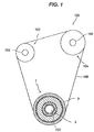
- FIG. 1 A first embodiment of the invention will be described. As shown in Fig. 1 , this embodiment describes an example where the invention is applied to a drive pulley structure 1 that is used in an auxiliary driving belt system 100 that drives an auxiliary (a water pump or an alternator) by torque of an output shaft 101 of a motor vehicle engine. Note that the drive pulley structure 1 is used to suppress a variation in tension of a transmission belt 106 that is attributed to a change in rotation of the engine.
- Fig. 1 is a schematic block diagram of the auxiliary driving belt system 100 of this embodiment.
- the auxiliary driving belt system 100 has the drive pulley structure 1 (a pulley structure) that is connected to the output shaft 101 of the engine (a crankshaft of a reciprocating engine or an eccentric shaft of a rotary engine), driven shafts (auxiliary shafts) 102, 103 that are connected to auxiliaries such as a water pump and an alternator, a driven pulley structure 104 that is mounted on the driven shaft 102, a driven pulley structure 107 that is mounted on the driven shaft 103 and the transmission belt 106 that is looped over the drive pulley structure 1, the driven pulley structure 104, and the driven pulley structure 107.
- a V ribbed belt having a plurality of V-shaped ribs that extend parallel to each other along a longitudinal direction of the belt is used as the transmission belt 106.
- the transmission belt 106 is driven by virtue of the rotation of the drive pulley structure 1. Then, the driven pulley structure 104 and the driven pulley structure 107 are driven to rotate as the transmission belt 106 runs in loop, whereby although not shown, the auxiliaries such as the water pump and the alternator that are connected to the driven shafts 102, 103 are driven.
- Fig. 2 is a plan view of the drive pulley structure 1.
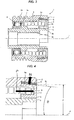
- Fig. 3 is a sectional view taken along the line A-A which contains a rotation axis J of the drive pulley structure 1 shown in Fig. 2 .
- Fig. 4 is a diagram showing in detail the drive pulley structure 1 shown in Fig. 3 .
- the drive pulley structure 1 has a cylindrical pulley member 2 around which the transmission belt 106 is laid to extend, a hub structure 3 that is connected to the output shaft 101 and which is provided inside the pulley member 2, a coil spring 4 that is fixed to the hub structure 3 at one end 4a thereof, a tapering 5 to which the other end 4b of the coil spring 4 is fixed and which has an outer circumferential surface 5a having a conical round surface as of part of a cone whose axis is made up of the rotational axis J of the hub structure 3, and a frictional member 6 that is inserted to be interposed between the outer circumferential surface 5a of the tapering 5 that has the conical round surface as of the cone and the pulley member 2.
- the pulley member 2 and the hub structure 3 are connected so as to rotate relative to each other via a rolling bearing 9.
- a slide bearing 8 is provided so as to be interposed between the hub structure 3 and the tapering 5.
- the pulley member 2 has a cylindrical shape, and a plurality of pulley grooves 2a are formed in an outer circumference of the pulley member 2 so as to extend in a circumferential direction thereof. Then, the transmission belt 106 is laid to extend around the outer circumference of the pulley member 2 in such a state that the plurality of V-shaped ribs that are provided on an inner circumference of the transmission belt 106 are in engagement with the corresponding pulley grooves 2a.
- the hub structure 3 has also a cylindrical shape.
- the output shaft 101 is fitted in a cylindrical interior portion 3a of the hub structure 3 so as to extend therethrough.
- the output shaft 101 and the hub structure 3 are connected together by appropriate connecting devices such as bolts so as not to rotate relative to each other.
- a non-magnetic material a paramagnetic material, a diamagnetic material or an anti-ferromagnetic material
- a non-magnetic material for example, an aluminum alloy, a titanium alloy or a synthetic resin is raised. Note that the pulley member 2 and the hub structure 3 are connected together so as to rotate relative to each other via the rolling bearing 9.
- the tapering 5 has a substantially U-shaped in section.
- An inner circumferential surface of the tapering 5 has a cylindrical shape, and an outer circumferential surface 5a thereof has the conical round surface as of part of the cone whose axis is made up of the rotational axis J of the hub structure 3.
- an angle ⁇ that is formed by an extension 5L of the outer circumferential surface 5a that is formed into the conical round surface and the rotational axis J is set to be in the range of 1° or larger to less than 90°.
- the slide bearing 8 is interposed between the hub structure 3 and the tapering 5, and the hub structure 3 and the tapering 5 are allowed to rotate relative to each other.
- the frictional member 6 is inserted to be interposed between the outer circumferential surface 5a having the conical round surface and the pulley member 2, and the frictional member 6 itself is fixed to the pulley member 2 so as not to rotate. It is preferable that the frictional member 6 is made of a material which is superior in wear resistance and resistance to compression deformation. For example, metals such as brass, plated brass, bronze and plated bronze and synthetic resins such as polyamide, polyacetal and polyarylate are raised. Additionally, a static friction coefficient between the tapering 5 and the frictional member 6 is set to a value that enables a relative slip to be generated between the tapering 5 and the frictional member 6 when a desired input torque is received.
- the static friction coefficient is set based on selected materials for the frictional member 6 and the tapering 5, a mode of a surface finish/configuration (for example, a configuration in which recesses and projections are arranged) of the frictional member 6 that is brought into abutment with the tapering 5 or the angle ⁇ formed by the extension 5L of the outer circumferential surface 5a and the rotational axis J.
- Used for the coil spring 4 is an angular coil spring in which an elongated linear member having a substantially rectangular cross section as shown in Fig. 3 is formed into a spiral shape. Additionally, the coil spring 4 is fixed to the hub structure 3 at the one end 4a thereof and is fixed to the tapering 5 at the other end 4b in such a state that the coil spring 4 is compressed in the direction of the rotational axis J. Then, the tapering 5 and the frictional member 6 are brought into press contact with each other by virtue of a restoring force P of the coil spring 4 so compressed.
- a frictional torque Tf that is generated between the outer circumferential surface 5a of the tapering 5 and the frictional member 6 when the outer circumferential surface 5a of the tapering 5 is brought into press contact with the frictional member 6 so as to press it by the vertical drag N expressed by the expression (1) above is expressed by the following expression (2).
- the relation between T and Tf is something like a relation expressed by the following expression (4), the coil spring 4 is not distorted in the circumferential direction, and a slip occurs on the abutment surface between the outer circumferential surface 5a of the tapering 5 and the frictional member 6, whereby the input torque T is absorbed by the slip.
- the tapering 5 is pressed for contact by the restoring force P of the coil spring 4, and the outer circumferential surface 5a having the conical round surface of the tapering 5 that is so pressed for contact is brought into press contact with the pulley member 2 via the frictional member 6 to press it.
- the frictional torque Tf is generated between the outer circumferential surface 5a having the conical round surface of the tapering 5 and the frictional member 6.
- a value for the frictional torque Tf that is generated between the outer circumferential surface 5a having the conical round surface of the tapering 5 and the frictional member 6 can be determined only by taking into consideration a static friction coefficient value between the frictional member 6 and the tapering 5.
- the pulley structure according to the invention may be applied to the driven pulley structures 104, 107 that are mounted on the driven shafts (the auxiliary shafts) 102, 103 that are connected to the auxiliaries such as the water pump and the alternator, respectively.
- the transmission belt 106 is driven by the rotation of the drive pulley structure 1. Then, as the transmission belt 106 runs in loop, torque is inputted from a pulley member 2 side of the driven pulley structure 104 or the driven pulley structure 107 to which the pulley structure according to the invention is applied.
- a drive pulley structure 201 according to a second embodiment will be described mainly with respect to different configurations from the first embodiment by omitting the description of similar configurations to those of the first embodiment.
- Fig. 5 is a plan view of the pulley structure 201.
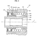
- Fig. 6 is a sectional view taken along the line B-B that contains a rotational axis J of the drive pulley structure 201 shown in Fig. 5 .
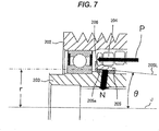
- Fig. 7 is a diagram showing in detail the drive pulley structure 201 shown in Fig. 6 .
- the drive pulley structure 201 has a cylindrical pulley member 202 around which a transmission belt 106 is laid to extend, a hub structure 203 that is connected to an output shaft 101 and which is provided inside the pulley member 202, a coil spring 204 that is fixed to the pulley member 202 at one end 204b thereof, a tapering 205 to which the other end 204a of the coil spring 204 is fixed and which has an inner circumferential surface 205a having a conical round surface as of part of a cone whose axis is made up of a rotational axis J of the hub structure 203, and a frictional member 206 that is inserted to be interposed between the inner circumferential surface 205a of the tapering 205 that has the conical round surface as of the cone and the hub structure 203.
- the pulley member 202 and the hub structure 203 are connected so as to rotate relative to each other via a rolling bearing 209 and a slide bearing
- the tapering 205 has a substantially cylindrical shape.
- the inner circumferential surface 205a of the tapering 205 has the conical round surface as of part of the cone whose axis is made up of the rotational axis J of the hub structure 203.
- an angle ⁇ that is formed by an extension 205L of the inner circumferential surface 205a that has the conical round surface and the rotational axis J is set to be in the range of 1° or larger to less than 90°.
- the frictional member 206 is inserted to be interposed between the inner circumferential surface 205a having the conical round surface and the hub structure 203, and the frictional member 206 itself is fixed to the hub structure 203 so as not to rotate.
- the coil spring 204 is fixed to the pulley member 202 at the one end 204b thereof and is fixed to the tapering 205 at the other end 204a in such a state that the coil spring 204 is compressed in the direction of the rotational axis J. Then, the tapering 205 and the frictional member 206 are brought into press contact with each other by virtue of a restoring force P of the coil spring 204 so compressed.
- the tapering 205 is pressed for contact by virtue of the restoring force P of the coil spring. Then, the inner circumferential surface 205a having the conical round surface of the tapering 205 that is so pressed for contact is brought into press contact with the frictional member 206 so as to press it by a vertical drag N that is expressed by the expression (1) described in the first embodiment in relation to the angle ⁇ that is formed by the extension 205L of the inner circumferential surface 205a and the rotational axis J when seen in section.
- a frictional torque Tf that is generated between the inner circumferential surface 205a of the tapering 205 and the frictional member 206 when the inner circumferential surface 205a of the tapering 205 is brought into press contact with the frictional member 206 so as to press it by the vertical drag N expressed by the expression (1) is expressed by the expression (2) that is described in the first embodiment.
- ⁇ is a static friction coefficient between the tapering 205 and the frictional member 206
- r is an average radius of the inner circumferential surface 205a having the conical round surface.
- the function of the drive pulley structure 201 of this embodiment will be described.
- the function of the drive pulley structure 1 will be described based on an assumption that the output shaft 101 rotates when the engine is started to rotate, whereby torque is inputted into the drive pulley structure 201 from a hub structure 203 side thereof via the output shaft 101.
- the relation between T and Tf is something like a relation (T>Tf) expressed by the expression (4) described above, the coil spring 204 is not distorted in the circumferential direction, but a slip occurs on the abutment surface between the inner circumferential surface 205a of the tapering 205 and the frictional member 206, whereby the input torque T is absorbed by the slip.
- the tapering 205 is pressed for contact by the restoring force P of the coil spring 204, and the inner circumferential surface 205a having the conical round surface of the tapering 205 that is so pressed for contact is brought into press contact with the hub structure 203 via the frictional member 206 to press it.
- the frictional torque Tf is generated between the inner circumferential surface 205a having the conical round surface of the tapering 205 and the frictional member 206.
- the frictional member 206 by fixing the frictional member 206 to the hub structure 203 so as not to rotate, the frictional member 206 is allowed to slip relative to the tapering 205 only.
- a value for the frictional torque Tf that is generated between the inner circumferential surface 205a having the conical round surface of the tapering 205 and the frictional member 206 can be determined only by taking into consideration a static friction coefficient value between the frictional member 206 and the tapering 205.
- a driven pulley structure 301 (a pulley structure) according to a third embodiment will be described mainly with respect to different configurations from the first embodiment by omitting the description of similar configurations to those of the first embodiment.
- the driven pulley structure 301 according to the third embodiment adopts a configuration in which a spring clutch construction is incorporated in a portion where the coil spring 4 of the drive pulley structure 1 is provided in the first embodiment.
- the third embodiment will be described as the driven pulley structure 301 according to the invention being mounted on the driven shaft 102 of the auxiliary driving belt system 100 shown in Fig. 1 for use as a driven pulley structure.
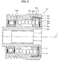
- Fig. 8 is a sectional view that contains a rotational axis J of the driven pulley structure 301.
- the configuration adopted in the first embodiment is not adopted in which the coil spring 4 of the drive pulley structure 1 is fixed directly to the tapering 5 at the other end 4b thereof, but as shown in Fig. 8 , a construction is adopted in which the other end 304b of a coil spring 304 is elastically deformed in a radially outward direction O, so that the coil spring 304 is locked to be mounted in a tapering 305 by virtue of a restoring force F (in a radially inward direction) thereof.
- one end 304a of the coil spring 304 is fixed to a hub structure 303.
- the function of the driven pulley structure 301 of this embodiment will be described.
- the function of the driven pulley structure 301 will be described based on a case where an output shaft 101 rotates when the engine is started to rotate and torque is inputted into the driven pulley structure 301 from a pulley member 302 side of the driven pulley structure 301 via the drive pulley structure 1 and the transmission belt 106.
- This case is based on an assumption that a rotational torque of the pulley member 302 exceeds a rotational torque of the hub structure 303 of the driven pulley structure 301 when the engine is started to rotate.
- the coil spring 304 is distorted in a circumferential direction and is kept held to the clutch surface 305c with a press contact engaging force relative to the clutch surface 305c increased, no slip occurring, whereby the rotation of the pulley member 302 is transmitted to the hub structure 303.
- an auxiliary such as a water pump or an alternator is driven which is connected to the driven shaft 102 that is mounted on the hub structure 303.
- the function of the driven pulley structure 301 will be described based on a case where although the rotational torque of the pulley member 302 is decreased via a transmission belt 106 when the output shaft 101 stops rotating as a result of the engine stopping rotating, the rotational torque of the hub structure 303 exceeds the rotational torque of the pulley member 302 due to the inertia produced when the engine rotates, that is, a case where torque is inputted into the driven pulley structure from a hub structure 303 side.
- the relation between the frictional torque Tf that is generated between the outer circumferential surface 305a of the tapering 305 and the frictional member 306 and the frictional torque Ts that is generated between the coil spring 304 and the clutch surface 305c is such that Ts ⁇ Tf.
- Tf the values of the frictional torques Ts, Tf (setting the values of Ts and Tf to different values)
- the rotational torque of the hub structure 303 exceeds the rotational torque of the pulley member 302 due to the inertia produced when the engine rotates, that is, a case where torque is inputted into the driven pulley structure 301 from the hub structure 303 side, with the relation between the frictional torques Tf, Ts being such that Tf ⁇ Ts, when the frictional torques are related to the input torque T so that Tf ⁇ T ⁇ Ts, the coil spring 304 is kept held to the clutch surface 305c with no slip caused to occur, while a slip is caused to occur on the abutment surface between the outer circumferential surface 305a of the tapering 305 and the frictional member 306, whereby the rotation of the hub structure 303 is not transmitted to the pulley member 302, and the hub structure 303 rotates freely.
- the driven pulley structure 301 functions in the same way also when the driven pulley structure 301 is mounted on the output shaft 101 for use as a drive pulley structure.
- the output shaft 101 rotates when the engine is started to rotate, and torque is inputted into the driven pulley structure 301 from the hub structure 303 side via the output shaft 101, whereby the rotational torque of the hub structure 303 exceeds the rotational torque of the pulley member 302.
- the third embodiment adopts the construction in which the other end 304b of the coil spring 304 is elastically deformed in the radially outward direction O so that the coil spring 304 is locked to be mounted in the tapering 305 by the restoring force F (in the radially inward direction) thereof.
- the invention is not limited thereto.
- a construction may be adopted in which the other end 304b of the coil spring 304 is elastically deformed in the radially inward direction so that the coil spring 304 is locked to be mounted in the tapering 305 by a restoring force (in the radially outward direction) thereof.
- the one end 304a of the coil spring 304 is fixed to the hub structure 303.
- the one end 304a of the coil spring 304 may be elastically deformed in the radially outward direction in place of being fixed to the hub structure 303 so that the one end 304a of the coil spring 304 is locked on the hub structure 303 by a restoring force (in the radially inward direction) thereof.
- the configuration is adopted in which the spring clutch construction is incorporated at the portion where the coil spring 4 of the drive pulley structure 1 is provided in the first embodiment.
- a configuration may be adopted in which the spring clutch construction is incorporated at the portion where the coil spring 204 of the drive pulley structure 201 is provided in the second embodiment.
- the other end 204a of the coil spring 204 is elastically deformed in the radially outward direction so that the coil spring 204 is locked in the tapering 205 by a restoring force (in the radially inward direction) thereof.
- the one end 204b of the coil spring 204 may be fixed to the pulley member 202 or may be elastically deformed in the radially outward (inward) direction, as with the other end 204a of the coil spring 204, so that the one end 204b of the coil spring 204 is locked on the pulley member 202 by a restoring force (in the radially inward (outward) direction) thereof.
- the two frictional torques which are the frictional torque Tf that is generated between the outer circumferential surface 305a having the conical round surface of the tapering 305 and the frictional member 306 and the frictional torque Ts that is generated between the other end 304b of the coil spring 304 and the clutch surface 305c of the tapering 305.
- the driven pulley structure 301 according to the invention is mounted on the driven shaft 102 for use as the driven pulley structure, with the input torque T inputted from the pulley member 302 side, in the event that the input torque T is larger than the frictional torque Tf that is generated between the outer circumferential surface 305a of the tapering 305 and the frictional member 306, the input torque T can be absorbed by causing a slip to occur on the abutment surface between the outer circumferential surface 305a of the tapering 305 and the frictional member 306.
Landscapes
- Engineering & Computer Science (AREA)
- General Engineering & Computer Science (AREA)
- Mechanical Engineering (AREA)
- Physics & Mathematics (AREA)
- Acoustics & Sound (AREA)
- Aviation & Aerospace Engineering (AREA)
- Pulleys (AREA)
- One-Way And Automatic Clutches, And Combinations Of Different Clutches (AREA)
- Devices For Conveying Motion By Means Of Endless Flexible Members (AREA)
Description
- The present invention relates to a pulley structure having a pulley member and a hub structure that can rotate relative to the pulley member.
- In general, as a transmission mechanism for transmitting the power of an engine of a motor vehicle, there is a belt transmission mechanism in which a belt is looped between pulleys. Additionally, as a pulley structure that is used in such a belt transmission mechanism, there is known a pulley structure having a configuration for damping a change in rotation when the change in rotation is generated in one of two rotational members (for example, Japanese Patent
3268007 - As a technique of this kind, this Japanese Patent discloses a pulley including an annular pulley member, a hub structure (to which a shaft of an alternating current generator is fixed so as not to rotate relative thereto), and a coil spring that is mounted between the annular pulley member and the hub structure. According to this configuration, when a change in rotation is generated in the hub structure, the coil spring between the hub structure and the annular pulley member is elastically deformed to thereby damp the change in rotation.
- However, when the natural frequency of the pulley described in Japanese Patent
3268007 - To cope with this problem, there has been proposed a pulley structure which adopts a spring clutch construction. As raised in
JP-A-2003-322174 - When a spring clutch construction like the one described above is adopted, since the coil spring is produced by using a plastic deformation technique, it is difficult to have uniform accuracy in dimension and profile, leading to a problem that a frictional torque generated between the end portion of the coil spring and the pulley member or the hub structure tends to vary easily. Additionally, the frictional torque generated between the end portion of the coil spring and the pulley member or the hub structure is determined by the material and performance of the coil spring and the pulley member or the hub structure. However, the selection of a material and a performance for a coil spring to be used is limited (the degree of freedom in design is lowered) from the viewpoint of ensuring the elastic force of the coil spring and ensuring the strength of the pulley member/the hub structure, resulting in a case where a frictional torque demanded by the user cannot be realized.
- Then, embodiments of the invention have been made with a view to solving the problems described above, which provide a pulley structure that can suppress the application of an excessive force to a coil spring to thereby prevent the breakage of the coil spring itself and which can increase the degree of freedom in design by changing freely the frictional torque while restricting the frictional torque to vary.
- Reference is also made to
EP-A-1754914 , in which decoupling of a bushing and conical element to decouple drive from a pulley to a pulley shaft in abnormal operating situations is achieved by virtue of the conical element moving backwards along a thread on the pulley shaft. Therefore, it is the thread that causes the decoupling. A coil spring is provided whose function is to prevent the decoupling from being complete. - A similar arrangement is disclosed in
US-A-2010/0147646 , disclosing the features of the preamble ofclaim 1. - According to the invention, there is provided a pulley structure comprising: a cylindrical pulley member around which a belt is laid to extend; a hub structure that is provided inside the pulley member so as to be rotatable relative to the pulley member; a coil spring that is fixed to the hub structure or the pulley member at one end thereof; a tapering to which the other end of the coil spring is fixed and which has a conical round surface as of a cone whose axis is made up of a rotational axis of the hub structure, such that an angle θ is formed by the extension of the conical round surface of the rotational axis of the hub structure when seen in section; and a frictional member that is inserted to be interposed between the conical round surface of the tapering and the pulley member or between the conical round surface of the tapering and the hub structure, wherein: the coil spring is inserted to be interposed in place while being compressed in the direction of the rotational axis of the hub structure to produce a restoring force P that acts, in said direction, to bring the tapering, the frictional member and the pulley member into press contact with each other or to bring the tapering, the frictional member and the hub structure into press contact with each other, in each case by an outward drag force N that the tapering applies to the frictional members, where N = Px sinθ.
- According to embodiments incorporating the configuration described above, the tapering is pressed for contact by virtue of the restoring force of the coil spring, and the conical round surface of the tapering that is so pressed for contact is then brought into press contact with the pulley member or the hub structure via the frictional member. By adopting this configuration, a frictional torque is generated between the conical round surface of the tapering and the frictional member. Then, when an input torque that is larger than this frictional torque is inputted from the pulley member or the hub structure, a relative slip is made to be generated between the conical round surface of the tapering and the frictional member on a press contact surface therebetween so as to prevent the coil spring from being distorted to a certain level or larger. By preventing the coil spring from being distorted to the certain level or larger in the way described above, the durability of the coil spring can be increased. Additionally, the frictional member and the tapering having the conical round surface can be produced with good accuracy by cutting or molding using a mold, and therefore, the frictional torque can be restricted from varying. In addition, by changing freely the material/performance of the frictional member, a desired frictional torque can be set, thereby making it possible to increase the degree of freedom in design.
- Additionally, according to an embodiment of the invention, the frictional member is fixed to the pulley member or the hub structure, so that the frictional member is allowed to slip relative to the tapering only.
- According to the configuration described above, by fixing the frictional member to the pulley member or the hub structure, the frictional member is allowed to slip relative to the tapering only. By adopting this configuration, a value for the frictional torque that is generated between the conical round surface of the tapering and the frictional member can be determined only by taking into consideration a static friction coefficient value between the frictional member and the tapering.
- In addition, according to another arrangement in accordance with the invention, the pulley structure is one wherein as a fixing form of the coil spring, a form is adopted in which at least one of one end and the other end of the coil spring is locked on at least one of the hub structure, the pulley member and the tapering by virtue of the restoring force of the coil spring while being elastically deformed in a radial direction, and a slip is generated when a rotational torque is inputted which is larger than a frictional torque that is generated between at least one of the one end and the other end of the coil spring and at least one of the hub structure, the pulley member and the tapering.
- According to the configuration described above, it is possible to generate the frictional torque that is generated between the conical round surface of the tapering and the frictional member and the frictional torque that is generated between at least one of the one end and the other end of the coil spring and at least one of the hub structure, the pulley member and the tapering. By adopting this configuration, the value of the frictional torque that is generated between the coil spring and at least one of the hub structure, the pulley member and the tapering and the value of the frictional torque that is generated between the conical round surface of the tapering and the frictional member can be changed freely so as to increase the degree of freedom in design.
- Additionally, according to a still further embodiment of the invention, the pulley structure is one wherein the frictional torque that is generated between the conical round surface of the tapering and the frictional member and the frictional torque that is generated between the coil spring and at least one of the hub structure, the pulley member and the tapering have different values.
- According to the configuration described above, by causing the frictional torque that is generated between the conical round surface of the tapering and the frictional member and the frictional torque that is generated between the coil spring and at least one of the hub structure, the pulley member and the tapering to have the different values, it is possible to determine based on the magnitude of a rotational torque that is inputted from the pulley member or the hub structure where to cause a slip to occur, that is, either between the conical round surface of the tapering and the frictional member or between the coil spring and at least one of the hub structure, the pulley member and the tapering.
- It is possible to provide the pulley structure that can suppress the application of an excessive force to the coil spring to thereby prevent the breakage of the coil spring itself and which can increase the degree of freedom in design by changing freely the frictional torque while restricting the frictional torque to vary.
- For a better understanding of the invention and to show how the same may be carried into effect, reference will now be made, by way of example, to the accompanying drawings, in which:
-
Fig. 1 is a schematic block diagram of an auxiliary driving belt system of a first embodiment. -
Fig. 2 is a plan view of a drive pulley structure according to the first embodiment. -
Fig. 3 is a sectional view taken along the line A-A that contains a rotational axis of the drive pulley structure shown inFig. 2 . -
Fig. 4 is a diagram showing in detail the drive pulley structure shown inFig. 3 . -
Fig. 5 is a plan view of a drive pulley structure according to a second embodiment. -
Fig. 6 is a sectional view taken along the line B-B that contains a rotational axis of the drive pulley structure shown inFig. 5 . -
Fig. 7 is a diagram showing in detail the drive pulley structure shown inFig. 6 . -
Fig. 8 is a sectional view that contains a rotational axis of a drive pulley structure according to a third embodiment. - A first embodiment of the invention will be described. As shown in
Fig. 1 , this embodiment describes an example where the invention is applied to adrive pulley structure 1 that is used in an auxiliarydriving belt system 100 that drives an auxiliary (a water pump or an alternator) by torque of anoutput shaft 101 of a motor vehicle engine. Note that thedrive pulley structure 1 is used to suppress a variation in tension of atransmission belt 106 that is attributed to a change in rotation of the engine. -
Fig. 1 is a schematic block diagram of the auxiliarydriving belt system 100 of this embodiment. As is shown inFig. 1 , the auxiliarydriving belt system 100 has the drive pulley structure 1 (a pulley structure) that is connected to theoutput shaft 101 of the engine (a crankshaft of a reciprocating engine or an eccentric shaft of a rotary engine), driven shafts (auxiliary shafts) 102, 103 that are connected to auxiliaries such as a water pump and an alternator, a drivenpulley structure 104 that is mounted on the drivenshaft 102, a drivenpulley structure 107 that is mounted on the drivenshaft 103 and thetransmission belt 106 that is looped over thedrive pulley structure 1, the drivenpulley structure 104, and the drivenpulley structure 107. In this embodiment, a V ribbed belt having a plurality of V-shaped ribs that extend parallel to each other along a longitudinal direction of the belt is used as thetransmission belt 106. - In the auxiliary
driving belt system 100, when thedrive pulley structure 1 is driven to rotate by the torque of theoutput shaft 101, thetransmission belt 106 is driven by virtue of the rotation of thedrive pulley structure 1. Then, the drivenpulley structure 104 and the drivenpulley structure 107 are driven to rotate as thetransmission belt 106 runs in loop, whereby although not shown, the auxiliaries such as the water pump and the alternator that are connected to the drivenshafts - Next, the
drive pulley structure 1 that is driven to rotate by virtue of the torque of theoutput shaft 101 will be described in detail.Fig. 2 is a plan view of thedrive pulley structure 1. Additionally,Fig. 3 is a sectional view taken along the line A-A which contains a rotation axis J of thedrive pulley structure 1 shown inFig. 2 . In addition,Fig. 4 is a diagram showing in detail thedrive pulley structure 1 shown inFig. 3 . - As shown in
Figs. 2 and3 , thedrive pulley structure 1 has acylindrical pulley member 2 around which thetransmission belt 106 is laid to extend, ahub structure 3 that is connected to theoutput shaft 101 and which is provided inside thepulley member 2, acoil spring 4 that is fixed to thehub structure 3 at oneend 4a thereof, a tapering 5 to which theother end 4b of thecoil spring 4 is fixed and which has an outercircumferential surface 5a having a conical round surface as of part of a cone whose axis is made up of the rotational axis J of thehub structure 3, and africtional member 6 that is inserted to be interposed between the outercircumferential surface 5a of the tapering 5 that has the conical round surface as of the cone and thepulley member 2. Additionally, thepulley member 2 and thehub structure 3 are connected so as to rotate relative to each other via a rolling bearing 9. Further, aslide bearing 8 is provided so as to be interposed between thehub structure 3 and thetapering 5. - The
pulley member 2 has a cylindrical shape, and a plurality ofpulley grooves 2a are formed in an outer circumference of thepulley member 2 so as to extend in a circumferential direction thereof. Then, thetransmission belt 106 is laid to extend around the outer circumference of thepulley member 2 in such a state that the plurality of V-shaped ribs that are provided on an inner circumference of thetransmission belt 106 are in engagement with the correspondingpulley grooves 2a. - The
hub structure 3 has also a cylindrical shape. Theoutput shaft 101 is fitted in a cylindricalinterior portion 3a of thehub structure 3 so as to extend therethrough. Theoutput shaft 101 and thehub structure 3 are connected together by appropriate connecting devices such as bolts so as not to rotate relative to each other. Additionally, as materials of which thepulley member 2 and thehub structure 3 are made, a non-magnetic material (a paramagnetic material, a diamagnetic material or an anti-ferromagnetic material) is raised for each of them. Specifically, as a non-magnetic material, for example, an aluminum alloy, a titanium alloy or a synthetic resin is raised. Note that thepulley member 2 and thehub structure 3 are connected together so as to rotate relative to each other via the rolling bearing 9. - As shown in
Fig. 3 , the tapering 5 has a substantially U-shaped in section. An inner circumferential surface of the tapering 5 has a cylindrical shape, and an outercircumferential surface 5a thereof has the conical round surface as of part of the cone whose axis is made up of the rotational axis J of thehub structure 3. Here, as shown inFig. 4 , when seen in section, an angle θ that is formed by anextension 5L of the outercircumferential surface 5a that is formed into the conical round surface and the rotational axis J is set to be in the range of 1° or larger to less than 90°. Theslide bearing 8 is interposed between thehub structure 3 and thetapering 5, and thehub structure 3 and the tapering 5 are allowed to rotate relative to each other. - The
frictional member 6 is inserted to be interposed between the outercircumferential surface 5a having the conical round surface and thepulley member 2, and thefrictional member 6 itself is fixed to thepulley member 2 so as not to rotate. It is preferable that thefrictional member 6 is made of a material which is superior in wear resistance and resistance to compression deformation. For example, metals such as brass, plated brass, bronze and plated bronze and synthetic resins such as polyamide, polyacetal and polyarylate are raised. Additionally, a static friction coefficient between the tapering 5 and thefrictional member 6 is set to a value that enables a relative slip to be generated between the tapering 5 and thefrictional member 6 when a desired input torque is received. Specifically, the static friction coefficient is set based on selected materials for thefrictional member 6 and thetapering 5, a mode of a surface finish/configuration (for example, a configuration in which recesses and projections are arranged) of thefrictional member 6 that is brought into abutment with the tapering 5 or the angle θ formed by theextension 5L of the outercircumferential surface 5a and the rotational axis J. - Used for the
coil spring 4 is an angular coil spring in which an elongated linear member having a substantially rectangular cross section as shown inFig. 3 is formed into a spiral shape. Additionally, thecoil spring 4 is fixed to thehub structure 3 at the oneend 4a thereof and is fixed to the tapering 5 at theother end 4b in such a state that thecoil spring 4 is compressed in the direction of the rotational axis J. Then, the tapering 5 and thefrictional member 6 are brought into press contact with each other by virtue of a restoring force P of thecoil spring 4 so compressed. - Specifically, as shown in
Fig. 4 , the tapering 5 is pressed for contact by virtue of the restoring force P of the coil spring. Then, the outercircumferential surface 5a having the conical round surface of the tapering 5 that is so pressed for contact is brought into press contact with thefrictional member 6 so as to press it by a vertical drag N that is expressed by the following expression (1) in relation to the angle θ that is formed by theextension 5L of the outercircumferential surface 5a and the rotational axis J when seen in section.
- In addition, a frictional torque Tf that is generated between the outer
circumferential surface 5a of the tapering 5 and thefrictional member 6 when the outercircumferential surface 5a of the tapering 5 is brought into press contact with thefrictional member 6 so as to press it by the vertical drag N expressed by the expression (1) above is expressed by the following expression (2).
- µ: Static friction coefficient between the tapering 5 and the
frictional member 6 - r: Average radius of the outer
circumferential surface 5a having the conical round surface. - Next, the function of the
drive pulley structure 1 of this embodiment will be described. Here, the function of thedrive pulley structure 1 will be described based on an assumption that theoutput shaft 101 rotates when the engine is started to rotate, whereby torque is inputted into thedrive pulley structure 1 from ahub structure 3 side thereof via theoutput shaft 101. Assuming that the torque that is inputted from thehub structure 3 side via theoutput shaft 101 is an input torque T (a variable), when the relation between T and Tf is something like a relation expressed by the following expression (3), there occurs no slip on an abutment surface between the outer circumferential surfaced 5a of the tapering 5 and thefrictional member 6, and thecoil spring 4 is distorted in a circumferential direction to thereby absorb the input torque T.
- On the other hand, the relation between T and Tf is something like a relation expressed by the following expression (4), the
coil spring 4 is not distorted in the circumferential direction, and a slip occurs on the abutment surface between the outercircumferential surface 5a of the tapering 5 and thefrictional member 6, whereby the input torque T is absorbed by the slip.
- According to the configuration described above, the tapering 5 is pressed for contact by the restoring force P of the
coil spring 4, and the outercircumferential surface 5a having the conical round surface of the tapering 5 that is so pressed for contact is brought into press contact with thepulley member 2 via thefrictional member 6 to press it. By doing so, the frictional torque Tf is generated between the outercircumferential surface 5a having the conical round surface of the tapering 5 and thefrictional member 6. Then, when the input torque T that is larger than the frictional torque Tf is inputted from thehub structure 3, a relative slip is caused to occur on the surface where the outercircumferential surface 5a having the conical round surface of the tapering 5 and thefrictional member 6 are pressed for contact with each other so that thecoil spring 4 can be prevented from being distorted to a certain level or larger. By preventing thecoil spring 4 from being distorted to the certain level or larger in this way, the durability of thecoil spring 4 can be increased. Additionally, thefrictional member 6 and the tapering 5 having the conical round surface that generate the frictional torque Tf can be produced with good accuracy by cutting or molding using a mold, and therefore, the frictional torque Tf can be restricted from varying. In addition, by changing freely the material/performance of thefrictional member 6, a desired frictional torque Tf can be set, thereby making it possible to increase the degree of freedom in design. - Additionally, according to the configuration described above, by fixing the
frictional member 6 to thepulley member 2 so as not to rotate, thefrictional member 6 is allowed to slip relative to the tapering 5 only. By doing so, a value for the frictional torque Tf that is generated between the outercircumferential surface 5a having the conical round surface of the tapering 5 and thefrictional member 6 can be determined only by taking into consideration a static friction coefficient value between thefrictional member 6 and thetapering 5. - In this embodiment, while the pulley structure according to the invention is applied to the drive
pulley structure 1 that is connected to theoutput shaft 101 of the engine, the pulley structure according to the invention may be applied to the drivenpulley structures - As this occurs, in the auxiliary
driving belt system 100, when thedrive pulley structure 1 is driven to rotate by the torque of theoutput shaft 101, thetransmission belt 106 is driven by the rotation of thedrive pulley structure 1. Then, as thetransmission belt 106 runs in loop, torque is inputted from apulley member 2 side of the drivenpulley structure 104 or the drivenpulley structure 107 to which the pulley structure according to the invention is applied. Assuming that the torque inputted is an input torque T (a variable), when the relation between T and Tf is something like the relation expressed by the expression (3), no slip occurs on the abutment surface between the outercircumferential surface 5a of the tapering 5 and thefrictional member 6, but thecoil spring 4 is distorted in the circumferential direction to thereby absorb the input torque T. On the other hand, when the relation between T and Tf is something like the relation expressed by the expression (4), thecoil spring 4 is not distorted in the circumferential direction, but a slip occurs on the abutment surface between the outercircumferential surface 5a of the tapering 5 and thefrictional member 6 to thereby absorb the input torque T. - Next, a
drive pulley structure 201 according to a second embodiment will be described mainly with respect to different configurations from the first embodiment by omitting the description of similar configurations to those of the first embodiment.Fig. 5 is a plan view of thepulley structure 201. Additionally,Fig. 6 is a sectional view taken along the line B-B that contains a rotational axis J of thedrive pulley structure 201 shown inFig. 5 . In addition,Fig. 7 is a diagram showing in detail thedrive pulley structure 201 shown inFig. 6 . - As shown in
Figs. 5 and6 , thedrive pulley structure 201 has acylindrical pulley member 202 around which atransmission belt 106 is laid to extend, ahub structure 203 that is connected to anoutput shaft 101 and which is provided inside thepulley member 202, acoil spring 204 that is fixed to thepulley member 202 at oneend 204b thereof, a tapering 205 to which theother end 204a of thecoil spring 204 is fixed and which has an innercircumferential surface 205a having a conical round surface as of part of a cone whose axis is made up of a rotational axis J of thehub structure 203, and africtional member 206 that is inserted to be interposed between the innercircumferential surface 205a of the tapering 205 that has the conical round surface as of the cone and thehub structure 203. Additionally, thepulley member 202 and thehub structure 203 are connected so as to rotate relative to each other via a rollingbearing 209 and aslide bearing 208. - As shown in
Fig. 6 , the tapering 205 has a substantially cylindrical shape. The innercircumferential surface 205a of the tapering 205 has the conical round surface as of part of the cone whose axis is made up of the rotational axis J of thehub structure 203. Here, as shown inFig. 7 , when seen in section, an angle θ that is formed by anextension 205L of the innercircumferential surface 205a that has the conical round surface and the rotational axis J is set to be in the range of 1° or larger to less than 90°. - The
frictional member 206 is inserted to be interposed between the innercircumferential surface 205a having the conical round surface and thehub structure 203, and thefrictional member 206 itself is fixed to thehub structure 203 so as not to rotate. - The
coil spring 204 is fixed to thepulley member 202 at the oneend 204b thereof and is fixed to the tapering 205 at theother end 204a in such a state that thecoil spring 204 is compressed in the direction of the rotational axis J. Then, the tapering 205 and thefrictional member 206 are brought into press contact with each other by virtue of a restoring force P of thecoil spring 204 so compressed. - Specifically, as shown in
Fig. 7 , the tapering 205 is pressed for contact by virtue of the restoring force P of the coil spring. Then, the innercircumferential surface 205a having the conical round surface of the tapering 205 that is so pressed for contact is brought into press contact with thefrictional member 206 so as to press it by a vertical drag N that is expressed by the expression (1) described in the first embodiment in relation to the angle θ that is formed by theextension 205L of the innercircumferential surface 205a and the rotational axis J when seen in section. - In addition, a frictional torque Tf that is generated between the inner
circumferential surface 205a of the tapering 205 and thefrictional member 206 when the innercircumferential surface 205a of the tapering 205 is brought into press contact with thefrictional member 206 so as to press it by the vertical drag N expressed by the expression (1) is expressed by the expression (2) that is described in the first embodiment. In the second embodiment, µ is a static friction coefficient between the tapering 205 and thefrictional member 206, and r is an average radius of the innercircumferential surface 205a having the conical round surface. - Next, the function of the
drive pulley structure 201 of this embodiment will be described. Here, the function of thedrive pulley structure 1 will be described based on an assumption that theoutput shaft 101 rotates when the engine is started to rotate, whereby torque is inputted into the drive pulley structure 201 from ahub structure 203 side thereof via theoutput shaft 101. Assuming that the torque that is inputted from thehub structure 203 side via theoutput shaft 101 is an input torque T (a variable), when the relation between T and Tf is something like a relation (T<Tf) expressed by the expression (3) described above, there occurs no slip on an abutment surface between the inner circumferential surfaced 205a of the tapering 205 and thefrictional member 206, but thecoil spring 204 is distorted in a circumferential direction to thereby absorb the input torque T. On the other hand, the relation between T and Tf is something like a relation (T>Tf) expressed by the expression (4) described above, thecoil spring 204 is not distorted in the circumferential direction, but a slip occurs on the abutment surface between the innercircumferential surface 205a of the tapering 205 and thefrictional member 206, whereby the input torque T is absorbed by the slip. - According to the configuration described above, the tapering 205 is pressed for contact by the restoring force P of the
coil spring 204, and the innercircumferential surface 205a having the conical round surface of the tapering 205 that is so pressed for contact is brought into press contact with thehub structure 203 via thefrictional member 206 to press it. By doing so, the frictional torque Tf is generated between the innercircumferential surface 205a having the conical round surface of the tapering 205 and thefrictional member 206. Then, when the input torque T that is larger than the frictional torque Tf is inputted from thehub structure 203, a relative slip is caused to occur on the surface where the innercircumferential surface 205a having the conical round surface of the tapering 205 and thefrictional member 206 are pressed for contact with each other so that thecoil spring 204 can be prevented from being distorted to a certain level or larger. By preventing thecoil spring 204 from being distorted to the certain level or larger in this way, the durability of thecoil spring 204 can be increased. Additionally, thefrictional member 206 and the tapering 205 having the conical round surface that generate the frictional torque Tf can be produced with good accuracy by cutting or molding using a mold, and therefore, the frictional torque Tf can be restricted from varying. In addition, by changing freely the material/performance of thefrictional member 206, a desired frictional torque Tf can be set, thereby making it possible to increase the degree of freedom in design. - Additionally, according to the configuration described above, by fixing the
frictional member 206 to thehub structure 203 so as not to rotate, thefrictional member 206 is allowed to slip relative to the tapering 205 only. By doing so, a value for the frictional torque Tf that is generated between the innercircumferential surface 205a having the conical round surface of the tapering 205 and thefrictional member 206 can be determined only by taking into consideration a static friction coefficient value between thefrictional member 206 and the tapering 205. - Next, a driven pulley structure 301 (a pulley structure) according to a third embodiment will be described mainly with respect to different configurations from the first embodiment by omitting the description of similar configurations to those of the first embodiment. As shown in
Fig. 8 , the drivenpulley structure 301 according to the third embodiment adopts a configuration in which a spring clutch construction is incorporated in a portion where thecoil spring 4 of thedrive pulley structure 1 is provided in the first embodiment. Additionally, the third embodiment will be described as the drivenpulley structure 301 according to the invention being mounted on the drivenshaft 102 of the auxiliarydriving belt system 100 shown inFig. 1 for use as a driven pulley structure.Fig. 8 is a sectional view that contains a rotational axis J of the drivenpulley structure 301. - In the driven
pulley structure 301 according to the third embodiment, the configuration adopted in the first embodiment is not adopted in which thecoil spring 4 of thedrive pulley structure 1 is fixed directly to the tapering 5 at theother end 4b thereof, but as shown inFig. 8 , a construction is adopted in which the other end 304b of acoil spring 304 is elastically deformed in a radially outward direction O, so that thecoil spring 304 is locked to be mounted in a tapering 305 by virtue of a restoring force F (in a radially inward direction) thereof. On the other hand, oneend 304a of thecoil spring 304 is fixed to ahub structure 303. - Next, the function of the driven
pulley structure 301 of this embodiment will be described. Firstly, the function of the drivenpulley structure 301 will be described based on a case where anoutput shaft 101 rotates when the engine is started to rotate and torque is inputted into the drivenpulley structure 301 from apulley member 302 side of the drivenpulley structure 301 via thedrive pulley structure 1 and thetransmission belt 106. This case is based on an assumption that a rotational torque of thepulley member 302 exceeds a rotational torque of thehub structure 303 of the drivenpulley structure 301 when the engine is started to rotate. - As in the case with the first embodiment, assuming that the torque that is inputted into the driven
pulley structure 301 from thepulley member 302 side is an input torque T (a variable) and that a frictional torque generated between an outercircumferential surface 305a of the tapering 305 and africtional member 306 is Tf, when the relation between T and Tf is something like the relation (T<Tf) expressed by the expression (3), no slip is produced on an abutment surface between the outercircumferential surface 305a of the tapering 305 and thefrictional member 306. Additionally, thecoil spring 304 is contracted in diameter as a result of the contact with aclutch surface 305c of the tapering 305. Then, thecoil spring 304 is distorted in a circumferential direction and is kept held to theclutch surface 305c with a press contact engaging force relative to theclutch surface 305c increased, no slip occurring, whereby the rotation of thepulley member 302 is transmitted to thehub structure 303. Then, an auxiliary such as a water pump or an alternator is driven which is connected to the drivenshaft 102 that is mounted on thehub structure 303. - On the other hand, when the relation between T and Tf is something like the relation (T>Tf) expressed by the expression (4), the
coil spring 304 is contracted in diameter as a result of the contact with theclutch surface 305c of the tapering 305 and is kept held to theclutch surface 305c with the press contact engaging force relative to theclutch surface 305c increased, no slip occurring. However, a slip occurs on the abutment surface between the outercircumferential surface 305a of the tapering 305 and thefrictional member 306 to thereby absorb the input torque T. By absorbing the input torque T in this way, the rotation of thepulley member 302 is not transmitted to thehub structure 303, and thepulley member 302 rotates freely. - Next, the function of the driven
pulley structure 301 will be described based on a case where although the rotational torque of thepulley member 302 is decreased via atransmission belt 106 when theoutput shaft 101 stops rotating as a result of the engine stopping rotating, the rotational torque of thehub structure 303 exceeds the rotational torque of thepulley member 302 due to the inertia produced when the engine rotates, that is, a case where torque is inputted into the driven pulley structure from ahub structure 303 side. - Assuming that the torque that is inputted into the driven
pulley structure 301 from thehub structure 303 side is an input torque T (a variable), that a frictional torque generated between the outercircumferential surface 305a of the tapering 305 and thefrictional member 306 is Tf and that a frictional torque generated between thecoil spring 304 and theclutch surface 305c is Ts, when the relation between the frictional torques is such that T<Ts<Tf, no slip occurs on the abutment surface between the outercircumferential surface 305a of the tapering 305 and thefrictional member 306. Additionally, thecoil spring 304 is kept held to theclutch surface 305c and no slip occurs, whereby the rotation of thehub structure 303 is transmitted to thepulley member 302. - In addition, when the relation between the frictional torques is such that Ts<T<Tf, no slip occurs on the abutment surface between the outer
circumferential surface 305a of the tapering 305 and thefrictional member 306. On the other hand, thecoil spring 304 is expanded in diameter, and the press contact engaging force relative to theclutch surface 305c is weakened, which causes a slip to occur at a contact portion between thecoil spring 304 and theclutch surface 305c. Thus, the rotation of thehub structure 303 is not transmitted to thepulley member 302, whereby thehub structure 303 rotates freely. - Further, when the relation between the frictional torques is such that Ts<Tf<T, the
coil spring 304 is expanded in diameter, and the press contact engaging force relative to theclutch surface 305c is weakened, which causes a slip to occur at the contact portion between thecoil spring 304 and theclutch surface 305c. Thus, the rotation of thehub structure 303 is not transmitted to thepulley member 302, whereby thehub structure 303 rotates freely. - Here, in the third embodiment, the relation between the frictional torque Tf that is generated between the outer
circumferential surface 305a of the tapering 305 and thefrictional member 306 and the frictional torque Ts that is generated between thecoil spring 304 and theclutch surface 305c is such that Ts<Tf. However, by setting freely the values of the frictional torques Ts, Tf (setting the values of Ts and Tf to different values), it is possible to determine based on the magnitude of the input torque T where to cause a slip to occur, that is, either between the outercircumferential surface 305a of the tapering 305 and thefrictional member 306 or between thecoil spring 304 and theclutch surface 305c. - For example, in describing a case where the rotational torque of the
hub structure 303 exceeds the rotational torque of thepulley member 302 due to the inertia produced when the engine rotates, that is, a case where torque is inputted into the drivenpulley structure 301 from thehub structure 303 side, with the relation between the frictional torques Tf, Ts being such that Tf<Ts, when the frictional torques are related to the input torque T so that Tf<T<Ts, thecoil spring 304 is kept held to theclutch surface 305c with no slip caused to occur, while a slip is caused to occur on the abutment surface between the outercircumferential surface 305a of the tapering 305 and thefrictional member 306, whereby the rotation of thehub structure 303 is not transmitted to thepulley member 302, and thehub structure 303 rotates freely. - In addition, when the frictional torques are related to the input torque T so that Tf<Ts<T, a slip is caused to occur on the abutment surface between the outer
circumferential surface 305a of the tapering 305 and thefrictional member 306, whereby the rotation of thehub structure 303 is not transmitted to thepulley member 302, and thehub structure 303 rotates freely. - Note that the driven
pulley structure 301 functions in the same way also when the drivenpulley structure 301 is mounted on theoutput shaft 101 for use as a drive pulley structure. In this case, theoutput shaft 101 rotates when the engine is started to rotate, and torque is inputted into the drivenpulley structure 301 from thehub structure 303 side via theoutput shaft 101, whereby the rotational torque of thehub structure 303 exceeds the rotational torque of thepulley member 302. On the other hand, when theoutput shaft 101 stops rotating as a result of the engine stopping rotating, the rotational torque of thepulley member 302 exceeds the rotational torque of thehub structure 303 due to thetransmission belt 106 being driven by the inertia, whereby torque is inputted into the drivenpulley structure 301 from thepulley member 302 side. - Additionally, the third embodiment adopts the construction in which the other end 304b of the
coil spring 304 is elastically deformed in the radially outward direction O so that thecoil spring 304 is locked to be mounted in the tapering 305 by the restoring force F (in the radially inward direction) thereof. However, the invention is not limited thereto. A construction may be adopted in which the other end 304b of thecoil spring 304 is elastically deformed in the radially inward direction so that thecoil spring 304 is locked to be mounted in the tapering 305 by a restoring force (in the radially outward direction) thereof. - In addition, in the third embodiment, the one
end 304a of thecoil spring 304 is fixed to thehub structure 303. However, as with the other end 304b of thecoil spring 304, the oneend 304a of thecoil spring 304 may be elastically deformed in the radially outward direction in place of being fixed to thehub structure 303 so that the oneend 304a of thecoil spring 304 is locked on thehub structure 303 by a restoring force (in the radially inward direction) thereof. - Additionally, in the driven
pulley structure 301 according to the third embodiment, the configuration is adopted in which the spring clutch construction is incorporated at the portion where thecoil spring 4 of thedrive pulley structure 1 is provided in the first embodiment. However, a configuration may be adopted in which the spring clutch construction is incorporated at the portion where thecoil spring 204 of thedrive pulley structure 201 is provided in the second embodiment. As this occurs, theother end 204a of thecoil spring 204 is elastically deformed in the radially outward direction so that thecoil spring 204 is locked in the tapering 205 by a restoring force (in the radially inward direction) thereof. Additionally, the oneend 204b of thecoil spring 204 may be fixed to thepulley member 202 or may be elastically deformed in the radially outward (inward) direction, as with theother end 204a of thecoil spring 204, so that the oneend 204b of thecoil spring 204 is locked on thepulley member 202 by a restoring force (in the radially inward (outward) direction) thereof. - According to the configuration described above, it is possible to generate the two frictional torques which are the frictional torque Tf that is generated between the outer
circumferential surface 305a having the conical round surface of the tapering 305 and thefrictional member 306 and the frictional torque Ts that is generated between the other end 304b of thecoil spring 304 and theclutch surface 305c of the tapering 305. By generating the two frictional forces in the way described above, for example, when the drivenpulley structure 301 according to the invention is mounted on the drivenshaft 102 for use as the driven pulley structure, with the input torque T inputted from thepulley member 302 side, in the event that the input torque T is larger than the frictional torque Tf that is generated between the outercircumferential surface 305a of the tapering 305 and thefrictional member 306, the input torque T can be absorbed by causing a slip to occur on the abutment surface between the outercircumferential surface 305a of the tapering 305 and thefrictional member 306. On the other hand, with the input torque T inputted from thehub structure 303 side, in the event that the respective frictional torques are related to the input torque T so that Ts<T<Tf, no slip is caused to occur on the abutment surface between the outercircumferential surface 305a of the tapering 305 and thefrictional member 306, but a slip is caused to occur in thecoil spring 304 at the contact portion between thecoil spring 304 and theclutch surface 305c. Thus, the rotation of thehub structure 303 is not transmitted to thepulley member 302, whereby thehub structure 303 is allowed to rotate freely. Further, in the event that the respective frictional torques are related to the input torque T so that Ts<Tf<T, a slip is caused to occur in thecoil spring 304 at the contact portion between thecoil spring 304 and theclutch surface 305c, and the rotation of thehub structure 303 is not transmitted to thepulley member 302, whereby thehub structure 303 is allowed to rotate freely. By adopting this configuration, it is possible to increase the degree of freedom in design by changing freely the values of the frictional torque Ts that is generated between the other end 304b of thecoil spring 304 and theclutch surface 305c of the tapering 305 and the frictional torque Tf that is generated between the outercircumferential surface 305a having the conical round surface of the tapering 305 and thefrictional member 306. - In addition, by setting freely the values of the frictional torques Ts, Tf (setting the values of Ts and Tf to different values), it is possible to determine based on the magnitude of the input torque T where to cause a slip to occur, that is, either between the outer
circumferential surface 305a of the tapering 305 and thefrictional member 306 or between thecoil spring 304 and theclutch surface 305c. -
- 1: 201:
- Drive pulley structure;
- 2, 202, 302:
- Pulley member
- 3, 203, 303:
- Hub structure
- 4, 204, 304:
- Coil spring
- 5, 205, 305:
- Tapering
- 6, 206, 306:
- Frictional member
- 100
- Auxiliary driving belt system
- 101, 104, 107, 301:
- Driven pulley structure
- 106:
- Transmission belt; J Rotational axis
Claims (4)
- A pulley structure comprising:a cylindrical pulley member (2; 202) around which a belt (106) is laid to extend;a hub structure (3; 203) that is provided inside the pulley member so as to be rotatable relative to the pulley member;a coil spring (4; 204) that is fixed to the hub structure (2) or the pulley member (202) at one end thereof;a tapering (5; 205) to which the other end of the coil spring is fixed and which has a conical round surface (5a; 205a) as of a cone whose axis is made up of a rotational axis (J) of the hub structure, such that an angle θ is formed by the extension (SL) of the conical round surface (5a; 205a) of the rotational axis (J) of the hub structure (3) when seen in section; anda frictional member (6; 206) that is inserted to be interposed between the conical round surface of the tapering (5) and the pulley member (2) or between the conical round surface of the tapering (205) and the hub structure (203), characterized in thatthe coil spring (4; 204) is inserted to be interposed in place while being compressed in the direction of the rotational axis of the hub structure (3; 203) to produce a restoring force P that acts, in said direction, to bring the tapering (5), the frictional member (6) and the pulley member (2) into press contact with each other or to bring the tapering, the frictional member and the hub structure into press contact with each other, in each case by an outward drag force N that the tapering (5; 205) applies to the frictional members (6; 206), where N = Px sinθ.
- The pulley structure as set forth in Claim 1, wherein
the frictional member (6; 206) is fixed to the pulley member (2) or the hub structure (203) so that the frictional member is allowed to slip relative to the tapering (5; 205) only. - The pulley structure as set forth in Claim 1, wherein:as a fixing form of the coil spring (304), a form is adopted in which at least one of one end and the other end of the coil spring (304) is locked on at least one of the hub structure, the pulley member and the tapering (305) by virtue of the restoring force of the coil spring while being elastically deformed in a radial direction; anda slip is generated when a rotational torque (T) is inputted which is larger than a frictional torque (Tf) that is generated between at least one of the one end and the other end of the coil spring (304) and at least one of the hub structure, the pulley member and the tapering.
- The pulley structure as set forth in Claim 3, wherein
the frictional torque (Tf) that is generated between the conical round surface (305a) of the tapering (305) and the frictional member (306) and the frictional torque (Ts) that is generated between the coil spring (304) and at least one of the hub structure, the pulley member and the tapering (305) have different values.
Applications Claiming Priority (2)
| Application Number | Priority Date | Filing Date | Title |
|---|---|---|---|
| JP2010193935A JP5515084B2 (en) | 2010-08-31 | 2010-08-31 | Pulley structure |
| PCT/JP2011/069669 WO2012029815A1 (en) | 2010-08-31 | 2011-08-30 | Pulley structure |
Publications (3)
| Publication Number | Publication Date |
|---|---|
| EP2626595A1 EP2626595A1 (en) | 2013-08-14 |
| EP2626595A4 EP2626595A4 (en) | 2014-02-26 |
| EP2626595B1 true EP2626595B1 (en) | 2019-08-07 |
Family
ID=45772895
Family Applications (1)
| Application Number | Title | Priority Date | Filing Date |
|---|---|---|---|
| EP11821830.4A Not-in-force EP2626595B1 (en) | 2010-08-31 | 2011-08-30 | Pulley structure |
Country Status (7)
| Country | Link |
|---|---|
| US (1) | US9638308B2 (en) |
| EP (1) | EP2626595B1 (en) |
| JP (1) | JP5515084B2 (en) |
| CN (1) | CN103080608B (en) |
| BR (1) | BR112013004876B1 (en) |
| CA (1) | CA2808060C (en) |
| WO (1) | WO2012029815A1 (en) |
Families Citing this family (22)
| Publication number | Priority date | Publication date | Assignee | Title |
|---|---|---|---|---|
| US8784244B2 (en) * | 2008-04-30 | 2014-07-22 | Dayco Ip Holdings, Llc | Pulley with asymmetric torque-sensitive clutching |
| US8888622B2 (en) * | 2012-06-04 | 2014-11-18 | The Gates Corporation | Isolator decoupler |
| CN102758860B (en) | 2012-07-27 | 2015-04-15 | 重庆大易用机械有限公司 | Conical-surface friction type overrunning clutch |
| US11236812B2 (en) * | 2012-09-10 | 2022-02-01 | Zen S/A Industria Metalurgica | Decoupler with one-way clutch and fail-safe system |
| BR102012022803B1 (en) * | 2012-09-10 | 2017-05-02 | Zen S/A Indústria Metalúrgica | decoupler with freewheel system and vibration damping |
| KR101500138B1 (en) * | 2013-09-10 | 2015-03-06 | 현대자동차주식회사 | Decoupling device of crank pully |
| CN105593548B (en) | 2013-10-01 | 2019-06-28 | 利滕斯汽车合伙公司 | Decoupler with controllable damping |
| US9169914B2 (en) * | 2014-03-07 | 2015-10-27 | Gates Corporation | Isolating decoupler |
| US9341254B2 (en) * | 2014-08-08 | 2016-05-17 | Gates Corporation | Isolating pulley |
| US9759274B2 (en) | 2014-08-18 | 2017-09-12 | Gates Corporation | Accessory tuning device with spring lock |
| JP6871851B2 (en) * | 2014-09-10 | 2021-05-19 | リテンズ オートモーティヴ パートナーシップ | Proportional damping power transmission device using torsional spring force |
| US9291253B1 (en) * | 2015-03-24 | 2016-03-22 | Gates Corporation | Isolating decoupler |
| US9784357B2 (en) * | 2015-04-27 | 2017-10-10 | Ningbo Yangtong Automobile Parts Co., Ltd. | Overrunning alternator damping pulley |
| KR101724471B1 (en) * | 2015-05-26 | 2017-04-18 | 현대자동차 주식회사 | Alternator unit having vibration reducing damper |
| US9618099B2 (en) | 2015-07-13 | 2017-04-11 | Gates Corporation | Tensioner with secondary damping |
| CN105715757A (en) * | 2016-04-12 | 2016-06-29 | 无锡凯能光伏设备有限公司 | Adjustable rotary drive device with safety clutch |
| JP6511085B2 (en) * | 2016-04-28 | 2019-05-15 | 三ツ星ベルト株式会社 | Pulley structure |
| FR3053394B1 (en) * | 2016-06-30 | 2019-08-09 | Hutchinson | DECOUPLING PULLEY WITH DEPARTURE CLUTCH |
| CN110462239B (en) | 2017-03-28 | 2022-05-10 | 利滕斯汽车合伙公司 | Isolation device having a selected angle between a spring stop and a damping member |
| JP6950954B2 (en) * | 2017-12-22 | 2021-10-13 | 国立大学法人金沢大学 | Liquid filling method, SIMM probe manufacturing method, SIMM probe and SIMM |
| US11549558B2 (en) | 2018-08-01 | 2023-01-10 | Gates Corporation | Isolator decoupler |
| JP2022039999A (en) * | 2020-08-28 | 2022-03-10 | 三ツ星ベルト株式会社 | Crank pulley device |
Family Cites Families (11)
| Publication number | Priority date | Publication date | Assignee | Title |
|---|---|---|---|---|
| US5139463A (en) | 1991-06-05 | 1992-08-18 | Litens Automotive Partnership | Serpentine drive with coil spring alternator connection |
| JP4013384B2 (en) * | 1999-02-05 | 2007-11-28 | 株式会社ジェイテクト | Pulley unit with one-way clutch |
| DE10012233A1 (en) * | 2000-03-14 | 2001-09-20 | Schaeffler Waelzlager Ohg | Automotive pulley drive wheel with friction slip clutch and helical spring on a hub |
| JP2003322174A (en) | 2002-05-07 | 2003-11-14 | Ntn Corp | Spring clutch |
| KR101167472B1 (en) * | 2003-12-09 | 2012-07-27 | 리텐스 오토모티브 파트너쉽 | Spring travel limiter for overrunning alternator decoupler |
| JP2006038183A (en) * | 2004-07-30 | 2006-02-09 | Koyo Seiko Co Ltd | Power transmission |
| JP5026687B2 (en) * | 2004-12-02 | 2012-09-12 | 三ツ星ベルト株式会社 | Pulley structure |
| WO2006081657A1 (en) * | 2005-02-03 | 2006-08-10 | Litens Automotive Partnership | Torque limited decoupler |
| EP1754914A1 (en) | 2005-08-19 | 2007-02-21 | Industrias Cántabras de Torneado S.R.L. | Alternator pulley |
| JP4957264B2 (en) * | 2007-01-24 | 2012-06-20 | 株式会社ジェイテクト | Pulley unit |
| US8529387B2 (en) * | 2008-04-30 | 2013-09-10 | Dayco Ip Holdings, Llc | Pulley with asymmetric torque-sensitive clutching |
-
2010
- 2010-08-31 JP JP2010193935A patent/JP5515084B2/en active Active
-
2011
- 2011-08-30 EP EP11821830.4A patent/EP2626595B1/en not_active Not-in-force
- 2011-08-30 CA CA2808060A patent/CA2808060C/en active Active
- 2011-08-30 CN CN201180042045.XA patent/CN103080608B/en not_active Expired - Fee Related
- 2011-08-30 BR BR112013004876-0A patent/BR112013004876B1/en not_active IP Right Cessation
- 2011-08-30 US US13/817,967 patent/US9638308B2/en active Active
- 2011-08-30 WO PCT/JP2011/069669 patent/WO2012029815A1/en active Application Filing
Non-Patent Citations (1)
| Title |
|---|
| None * |
Also Published As
| Publication number | Publication date |
|---|---|
| US9638308B2 (en) | 2017-05-02 |
| BR112013004876A2 (en) | 2016-05-03 |
| JP5515084B2 (en) | 2014-06-11 |
| EP2626595A1 (en) | 2013-08-14 |
| JP2012052576A (en) | 2012-03-15 |
| US20130150191A1 (en) | 2013-06-13 |
| WO2012029815A1 (en) | 2012-03-08 |
| CN103080608A (en) | 2013-05-01 |
| BR112013004876B1 (en) | 2020-09-29 |
| CA2808060A1 (en) | 2012-03-08 |
| CN103080608B (en) | 2016-01-20 |
| EP2626595A4 (en) | 2014-02-26 |
| CA2808060C (en) | 2018-05-22 |
Similar Documents
| Publication | Publication Date | Title |
|---|---|---|
| EP2626595B1 (en) | Pulley structure | |
| JP4641931B2 (en) | Pulleys for power transmission members, separate star towel tunators fitted with such pulleys, and engine drives | |
| JP4535517B2 (en) | Serpentine belt drive system with improved overrun alternator decoupler | |
| EP2652361B1 (en) | Isolator decoupler | |
| KR20080048076A (en) | Power transmission pulley | |
| US10677294B2 (en) | Decoupler assembly | |
| KR20140035347A (en) | Friction clutch plate with damping springs | |
| WO2006070422A1 (en) | A pulley assembly | |
| JP6490479B2 (en) | Alternator damper pulley for vehicles | |
| CN109312786B (en) | Belt pulley decoupler | |
| JP6254788B2 (en) | Torsional damper | |
| JP5800131B2 (en) | Torque fluctuation absorbing damper | |
| US11708886B2 (en) | Single spring, torsionally compliant, overrunning decoupler | |
| JP4743391B2 (en) | Torque fluctuation absorbing damper | |
| EP1725789B1 (en) | A pulley assembly | |
| EP3318779B1 (en) | Damper for absorbing rotational variation | |
| JP6009905B2 (en) | Rotation fluctuation absorbing damper pulley | |
| JP5257617B2 (en) | Torque fluctuation absorbing damper | |
| JP2008019979A (en) | Multi-shaft drive mechanism for transmission belt | |
| JP5910859B2 (en) | Torque fluctuation absorbing damper | |
| JP5569679B2 (en) | Torsional damper | |
| CN111550504A (en) | Decoupler for automobile generator | |
| MXPA97002717A (en) | Cigüe decoupler |
Legal Events
| Date | Code | Title | Description |
|---|---|---|---|
| PUAI | Public reference made under article 153(3) epc to a published international application that has entered the european phase |
Free format text: ORIGINAL CODE: 0009012 |
|
| 17P | Request for examination filed |
Effective date: 20130225 |
|
| AK | Designated contracting states |
Kind code of ref document: A1 Designated state(s): AL AT BE BG CH CY CZ DE DK EE ES FI FR GB GR HR HU IE IS IT LI LT LU LV MC MK MT NL NO PL PT RO RS SE SI SK SM TR |
|
| DAX | Request for extension of the european patent (deleted) | ||
| RIC1 | Information provided on ipc code assigned before grant |
Ipc: F16H 55/36 20060101AFI20140116BHEP Ipc: F16D 43/21 20060101ALI20140116BHEP |
|
| A4 | Supplementary search report drawn up and despatched |
Effective date: 20140129 |
|
| RIC1 | Information provided on ipc code assigned before grant |
Ipc: F16D 43/21 20060101ALI20140123BHEP Ipc: F16H 55/36 20060101AFI20140123BHEP |
|
| 17Q | First examination report despatched |
Effective date: 20140908 |
|
| STAA | Information on the status of an ep patent application or granted ep patent |
Free format text: STATUS: EXAMINATION IS IN PROGRESS |
|
| GRAP | Despatch of communication of intention to grant a patent |
Free format text: ORIGINAL CODE: EPIDOSNIGR1 |
|
| STAA | Information on the status of an ep patent application or granted ep patent |
Free format text: STATUS: GRANT OF PATENT IS INTENDED |
|
| INTG | Intention to grant announced |
Effective date: 20190307 |
|
| GRAS | Grant fee paid |
Free format text: ORIGINAL CODE: EPIDOSNIGR3 |
|
| GRAA | (expected) grant |
Free format text: ORIGINAL CODE: 0009210 |
|
| STAA | Information on the status of an ep patent application or granted ep patent |
Free format text: STATUS: THE PATENT HAS BEEN GRANTED |
|
| AK | Designated contracting states |
Kind code of ref document: B1 Designated state(s): AL AT BE BG CH CY CZ DE DK EE ES FI FR GB GR HR HU IE IS IT LI LT LU LV MC MK MT NL NO PL PT RO RS SE SI SK SM TR |
|
| REG | Reference to a national code |
Ref country code: GB Ref legal event code: FG4D |
|
| REG | Reference to a national code |
Ref country code: CH Ref legal event code: EP Ref country code: AT Ref legal event code: REF Ref document number: 1164380 Country of ref document: AT Kind code of ref document: T Effective date: 20190815 |
|
| REG | Reference to a national code |
Ref country code: DE Ref legal event code: R096 Ref document number: 602011061136 Country of ref document: DE |
|
| REG | Reference to a national code |
Ref country code: IE Ref legal event code: FG4D |
|
| REG | Reference to a national code |
Ref country code: NL Ref legal event code: MP Effective date: 20190807 |
|
| REG | Reference to a national code |
Ref country code: LT Ref legal event code: MG4D |
|
| PG25 | Lapsed in a contracting state [announced via postgrant information from national office to epo] |
Ref country code: FI Free format text: LAPSE BECAUSE OF FAILURE TO SUBMIT A TRANSLATION OF THE DESCRIPTION OR TO PAY THE FEE WITHIN THE PRESCRIBED TIME-LIMIT Effective date: 20190807 Ref country code: LT Free format text: LAPSE BECAUSE OF FAILURE TO SUBMIT A TRANSLATION OF THE DESCRIPTION OR TO PAY THE FEE WITHIN THE PRESCRIBED TIME-LIMIT Effective date: 20190807 Ref country code: PT Free format text: LAPSE BECAUSE OF FAILURE TO SUBMIT A TRANSLATION OF THE DESCRIPTION OR TO PAY THE FEE WITHIN THE PRESCRIBED TIME-LIMIT Effective date: 20191209 Ref country code: HR Free format text: LAPSE BECAUSE OF FAILURE TO SUBMIT A TRANSLATION OF THE DESCRIPTION OR TO PAY THE FEE WITHIN THE PRESCRIBED TIME-LIMIT Effective date: 20190807 Ref country code: NO Free format text: LAPSE BECAUSE OF FAILURE TO SUBMIT A TRANSLATION OF THE DESCRIPTION OR TO PAY THE FEE WITHIN THE PRESCRIBED TIME-LIMIT Effective date: 20191107 Ref country code: SE Free format text: LAPSE BECAUSE OF FAILURE TO SUBMIT A TRANSLATION OF THE DESCRIPTION OR TO PAY THE FEE WITHIN THE PRESCRIBED TIME-LIMIT Effective date: 20190807 Ref country code: BG Free format text: LAPSE BECAUSE OF FAILURE TO SUBMIT A TRANSLATION OF THE DESCRIPTION OR TO PAY THE FEE WITHIN THE PRESCRIBED TIME-LIMIT Effective date: 20191107 Ref country code: NL Free format text: LAPSE BECAUSE OF FAILURE TO SUBMIT A TRANSLATION OF THE DESCRIPTION OR TO PAY THE FEE WITHIN THE PRESCRIBED TIME-LIMIT Effective date: 20190807 |
|
| REG | Reference to a national code |
Ref country code: AT Ref legal event code: MK05 Ref document number: 1164380 Country of ref document: AT Kind code of ref document: T Effective date: 20190807 |
|
| PG25 | Lapsed in a contracting state [announced via postgrant information from national office to epo] |
Ref country code: ES Free format text: LAPSE BECAUSE OF FAILURE TO SUBMIT A TRANSLATION OF THE DESCRIPTION OR TO PAY THE FEE WITHIN THE PRESCRIBED TIME-LIMIT Effective date: 20190807 Ref country code: AL Free format text: LAPSE BECAUSE OF FAILURE TO SUBMIT A TRANSLATION OF THE DESCRIPTION OR TO PAY THE FEE WITHIN THE PRESCRIBED TIME-LIMIT Effective date: 20190807 Ref country code: LV Free format text: LAPSE BECAUSE OF FAILURE TO SUBMIT A TRANSLATION OF THE DESCRIPTION OR TO PAY THE FEE WITHIN THE PRESCRIBED TIME-LIMIT Effective date: 20190807 Ref country code: IS Free format text: LAPSE BECAUSE OF FAILURE TO SUBMIT A TRANSLATION OF THE DESCRIPTION OR TO PAY THE FEE WITHIN THE PRESCRIBED TIME-LIMIT Effective date: 20191207 Ref country code: RS Free format text: LAPSE BECAUSE OF FAILURE TO SUBMIT A TRANSLATION OF THE DESCRIPTION OR TO PAY THE FEE WITHIN THE PRESCRIBED TIME-LIMIT Effective date: 20190807 Ref country code: GR Free format text: LAPSE BECAUSE OF FAILURE TO SUBMIT A TRANSLATION OF THE DESCRIPTION OR TO PAY THE FEE WITHIN THE PRESCRIBED TIME-LIMIT Effective date: 20191108 |
|
| PG25 | Lapsed in a contracting state [announced via postgrant information from national office to epo] |
Ref country code: TR Free format text: LAPSE BECAUSE OF FAILURE TO SUBMIT A TRANSLATION OF THE DESCRIPTION OR TO PAY THE FEE WITHIN THE PRESCRIBED TIME-LIMIT Effective date: 20190807 |
|
| PG25 | Lapsed in a contracting state [announced via postgrant information from national office to epo] |
Ref country code: EE Free format text: LAPSE BECAUSE OF FAILURE TO SUBMIT A TRANSLATION OF THE DESCRIPTION OR TO PAY THE FEE WITHIN THE PRESCRIBED TIME-LIMIT Effective date: 20190807 Ref country code: PL Free format text: LAPSE BECAUSE OF FAILURE TO SUBMIT A TRANSLATION OF THE DESCRIPTION OR TO PAY THE FEE WITHIN THE PRESCRIBED TIME-LIMIT Effective date: 20190807 Ref country code: AT Free format text: LAPSE BECAUSE OF FAILURE TO SUBMIT A TRANSLATION OF THE DESCRIPTION OR TO PAY THE FEE WITHIN THE PRESCRIBED TIME-LIMIT Effective date: 20190807 Ref country code: RO Free format text: LAPSE BECAUSE OF FAILURE TO SUBMIT A TRANSLATION OF THE DESCRIPTION OR TO PAY THE FEE WITHIN THE PRESCRIBED TIME-LIMIT Effective date: 20190807 Ref country code: DK Free format text: LAPSE BECAUSE OF FAILURE TO SUBMIT A TRANSLATION OF THE DESCRIPTION OR TO PAY THE FEE WITHIN THE PRESCRIBED TIME-LIMIT Effective date: 20190807 |
|
| PG25 | Lapsed in a contracting state [announced via postgrant information from national office to epo] |
Ref country code: SK Free format text: LAPSE BECAUSE OF FAILURE TO SUBMIT A TRANSLATION OF THE DESCRIPTION OR TO PAY THE FEE WITHIN THE PRESCRIBED TIME-LIMIT Effective date: 20190807 Ref country code: LI Free format text: LAPSE BECAUSE OF NON-PAYMENT OF DUE FEES Effective date: 20190831 Ref country code: IS Free format text: LAPSE BECAUSE OF FAILURE TO SUBMIT A TRANSLATION OF THE DESCRIPTION OR TO PAY THE FEE WITHIN THE PRESCRIBED TIME-LIMIT Effective date: 20200224 Ref country code: SM Free format text: LAPSE BECAUSE OF FAILURE TO SUBMIT A TRANSLATION OF THE DESCRIPTION OR TO PAY THE FEE WITHIN THE PRESCRIBED TIME-LIMIT Effective date: 20190807 Ref country code: LU Free format text: LAPSE BECAUSE OF NON-PAYMENT OF DUE FEES Effective date: 20190830 Ref country code: CH Free format text: LAPSE BECAUSE OF NON-PAYMENT OF DUE FEES Effective date: 20190831 Ref country code: MC Free format text: LAPSE BECAUSE OF FAILURE TO SUBMIT A TRANSLATION OF THE DESCRIPTION OR TO PAY THE FEE WITHIN THE PRESCRIBED TIME-LIMIT Effective date: 20190807 Ref country code: CZ Free format text: LAPSE BECAUSE OF FAILURE TO SUBMIT A TRANSLATION OF THE DESCRIPTION OR TO PAY THE FEE WITHIN THE PRESCRIBED TIME-LIMIT Effective date: 20190807 |
|
| REG | Reference to a national code |
Ref country code: BE Ref legal event code: MM Effective date: 20190831 |
|
| REG | Reference to a national code |
Ref country code: DE Ref legal event code: R097 Ref document number: 602011061136 Country of ref document: DE |
|
| PLBE | No opposition filed within time limit |
Free format text: ORIGINAL CODE: 0009261 |
|
| STAA | Information on the status of an ep patent application or granted ep patent |
Free format text: STATUS: NO OPPOSITION FILED WITHIN TIME LIMIT |
|
| PG2D | Information on lapse in contracting state deleted |
Ref country code: IS |
|
| PG25 | Lapsed in a contracting state [announced via postgrant information from national office to epo] |
Ref country code: IE Free format text: LAPSE BECAUSE OF NON-PAYMENT OF DUE FEES Effective date: 20190830 |
|
| 26N | No opposition filed |
Effective date: 20200603 |
|
| PG25 | Lapsed in a contracting state [announced via postgrant information from national office to epo] |
Ref country code: SI Free format text: LAPSE BECAUSE OF FAILURE TO SUBMIT A TRANSLATION OF THE DESCRIPTION OR TO PAY THE FEE WITHIN THE PRESCRIBED TIME-LIMIT Effective date: 20190807 Ref country code: BE Free format text: LAPSE BECAUSE OF NON-PAYMENT OF DUE FEES Effective date: 20190831 |
|
| PG25 | Lapsed in a contracting state [announced via postgrant information from national office to epo] |
Ref country code: CY Free format text: LAPSE BECAUSE OF FAILURE TO SUBMIT A TRANSLATION OF THE DESCRIPTION OR TO PAY THE FEE WITHIN THE PRESCRIBED TIME-LIMIT Effective date: 20190807 |
|
| PG25 | Lapsed in a contracting state [announced via postgrant information from national office to epo] |
Ref country code: HU Free format text: LAPSE BECAUSE OF FAILURE TO SUBMIT A TRANSLATION OF THE DESCRIPTION OR TO PAY THE FEE WITHIN THE PRESCRIBED TIME-LIMIT; INVALID AB INITIO Effective date: 20110830 Ref country code: MT Free format text: LAPSE BECAUSE OF FAILURE TO SUBMIT A TRANSLATION OF THE DESCRIPTION OR TO PAY THE FEE WITHIN THE PRESCRIBED TIME-LIMIT Effective date: 20190807 |
|
| PG25 | Lapsed in a contracting state [announced via postgrant information from national office to epo] |
Ref country code: MK Free format text: LAPSE BECAUSE OF FAILURE TO SUBMIT A TRANSLATION OF THE DESCRIPTION OR TO PAY THE FEE WITHIN THE PRESCRIBED TIME-LIMIT Effective date: 20190807 |
|
| PGFP | Annual fee paid to national office [announced via postgrant information from national office to epo] |
Ref country code: IT Payment date: 20220712 Year of fee payment: 12 Ref country code: GB Payment date: 20220707 Year of fee payment: 12 Ref country code: DE Payment date: 20220712 Year of fee payment: 12 |
|
| PGFP | Annual fee paid to national office [announced via postgrant information from national office to epo] |
Ref country code: FR Payment date: 20220709 Year of fee payment: 12 |
|
| P01 | Opt-out of the competence of the unified patent court (upc) registered |
Effective date: 20230420 |
|
| REG | Reference to a national code |
Ref country code: DE Ref legal event code: R119 Ref document number: 602011061136 Country of ref document: DE |
|
| GBPC | Gb: european patent ceased through non-payment of renewal fee |
Effective date: 20230830 |
|
| PG25 | Lapsed in a contracting state [announced via postgrant information from national office to epo] |
Ref country code: GB Free format text: LAPSE BECAUSE OF NON-PAYMENT OF DUE FEES Effective date: 20230830 |
|
| PG25 | Lapsed in a contracting state [announced via postgrant information from national office to epo] |
Ref country code: IT Free format text: LAPSE BECAUSE OF NON-PAYMENT OF DUE FEES Effective date: 20230830 Ref country code: GB Free format text: LAPSE BECAUSE OF NON-PAYMENT OF DUE FEES Effective date: 20230830 Ref country code: FR Free format text: LAPSE BECAUSE OF NON-PAYMENT OF DUE FEES Effective date: 20230831 Ref country code: DE Free format text: LAPSE BECAUSE OF NON-PAYMENT OF DUE FEES Effective date: 20240301 |