BR112013004876B1 - PULLEY STRUCTURE - Google Patents
PULLEY STRUCTURE Download PDFInfo
- Publication number
- BR112013004876B1 BR112013004876B1 BR112013004876-0A BR112013004876A BR112013004876B1 BR 112013004876 B1 BR112013004876 B1 BR 112013004876B1 BR 112013004876 A BR112013004876 A BR 112013004876A BR 112013004876 B1 BR112013004876 B1 BR 112013004876B1
- Authority
- BR
- Brazil
- Prior art keywords
- pulley
- torque
- coil spring
- frictional
- helical spring
- Prior art date
Links
Images


Classifications
-
- F—MECHANICAL ENGINEERING; LIGHTING; HEATING; WEAPONS; BLASTING
- F16—ENGINEERING ELEMENTS AND UNITS; GENERAL MEASURES FOR PRODUCING AND MAINTAINING EFFECTIVE FUNCTIONING OF MACHINES OR INSTALLATIONS; THERMAL INSULATION IN GENERAL
- F16H—GEARING
- F16H55/00—Elements with teeth or friction surfaces for conveying motion; Worms, pulleys or sheaves for gearing mechanisms
- F16H55/32—Friction members
- F16H55/36—Pulleys
-
- F—MECHANICAL ENGINEERING; LIGHTING; HEATING; WEAPONS; BLASTING
- F16—ENGINEERING ELEMENTS AND UNITS; GENERAL MEASURES FOR PRODUCING AND MAINTAINING EFFECTIVE FUNCTIONING OF MACHINES OR INSTALLATIONS; THERMAL INSULATION IN GENERAL
- F16D—COUPLINGS FOR TRANSMITTING ROTATION; CLUTCHES; BRAKES
- F16D3/00—Yielding couplings, i.e. with means permitting movement between the connected parts during the drive
- F16D3/02—Yielding couplings, i.e. with means permitting movement between the connected parts during the drive adapted to specific functions
- F16D3/12—Yielding couplings, i.e. with means permitting movement between the connected parts during the drive adapted to specific functions specially adapted for accumulation of energy to absorb shocks or vibration
-
- F—MECHANICAL ENGINEERING; LIGHTING; HEATING; WEAPONS; BLASTING
- F16—ENGINEERING ELEMENTS AND UNITS; GENERAL MEASURES FOR PRODUCING AND MAINTAINING EFFECTIVE FUNCTIONING OF MACHINES OR INSTALLATIONS; THERMAL INSULATION IN GENERAL
- F16D—COUPLINGS FOR TRANSMITTING ROTATION; CLUTCHES; BRAKES
- F16D7/00—Slip couplings, e.g. slipping on overload, for absorbing shock
- F16D7/02—Slip couplings, e.g. slipping on overload, for absorbing shock of the friction type
- F16D7/024—Slip couplings, e.g. slipping on overload, for absorbing shock of the friction type with axially applied torque limiting friction surfaces
- F16D7/028—Slip couplings, e.g. slipping on overload, for absorbing shock of the friction type with axially applied torque limiting friction surfaces with conical friction surfaces
-
- F—MECHANICAL ENGINEERING; LIGHTING; HEATING; WEAPONS; BLASTING
- F16—ENGINEERING ELEMENTS AND UNITS; GENERAL MEASURES FOR PRODUCING AND MAINTAINING EFFECTIVE FUNCTIONING OF MACHINES OR INSTALLATIONS; THERMAL INSULATION IN GENERAL
- F16F—SPRINGS; SHOCK-ABSORBERS; MEANS FOR DAMPING VIBRATION
- F16F15/00—Suppression of vibrations in systems; Means or arrangements for avoiding or reducing out-of-balance forces, e.g. due to motion
- F16F15/10—Suppression of vibrations in rotating systems by making use of members moving with the system
- F16F15/12—Suppression of vibrations in rotating systems by making use of members moving with the system using elastic members or friction-damping members, e.g. between a rotating shaft and a gyratory mass mounted thereon
- F16F15/121—Suppression of vibrations in rotating systems by making use of members moving with the system using elastic members or friction-damping members, e.g. between a rotating shaft and a gyratory mass mounted thereon using springs as elastic members, e.g. metallic springs
- F16F15/123—Wound springs
-
- F—MECHANICAL ENGINEERING; LIGHTING; HEATING; WEAPONS; BLASTING
- F16—ENGINEERING ELEMENTS AND UNITS; GENERAL MEASURES FOR PRODUCING AND MAINTAINING EFFECTIVE FUNCTIONING OF MACHINES OR INSTALLATIONS; THERMAL INSULATION IN GENERAL
- F16H—GEARING
- F16H55/00—Elements with teeth or friction surfaces for conveying motion; Worms, pulleys or sheaves for gearing mechanisms
- F16H55/32—Friction members
- F16H55/36—Pulleys
- F16H2055/366—Pulleys with means providing resilience or vibration damping
Abstract
estrutura de polia é proposta uma estrutura de polia que pode eliminar a aplicação de uma força excessiva a uma mola helicoidal para assim impedir a quebra da mola helicoidal propriamente dita e que pode permitir um projeto com um grau de liberdade maior por alterar livremente o binário de fricção, restringindo ao mesmo tempo a capacidade de variação do binário de fricção. uma estrutura de polia de acionamento 1 tem um elemento cilíndrico de polia 2 ao redor do qual se estende uma correia de transmissão 106, uma estrutura de cubo 3 que é prevista no interior do elemento de polia 2, de modo a girar em relação ao elemento de polia 2, uma mola helicoidal 4 que é fixada à estrutura de cubo 3 em uma extremidade 4a sua, uma parte afusada 5 à qual a outra extremidade 4b da mola helicoidal 4 está fixada e que tem uma superfície arredondada cônica como se fosse parte de um cone cujo eixo é constituído pelo eixo de rotação j da estrutura de cubo 3, e um elemento friccional 6 que é inserido de modo a ficar interposto entre a superfície arredondada cônica da parte afusada 5 e o elemento de polia 2, e a mola helicoidal 4 está inserida para ficar interposta em seu lugar enquanto estiver sendo comprimida na direção do eixo de rotação j da estrutura de cubo 3, sendo a parte afusada 5, o elemento friccional 6 e o elemento de polia 2 levados a ficarem em contato com compressão entre si por força de restauração p da mola helicoidal 4.pulley structure a pulley structure is proposed that can eliminate the application of an excessive force to a coil spring in order to prevent the coil spring itself from breaking and which can allow a project with a greater degree of freedom by freely changing the torque of friction, while restricting the ability to vary the friction torque. a drive pulley structure 1 has a cylindrical pulley element 2 around which a transmission belt 106 extends, a hub structure 3 which is provided within the pulley element 2 so as to rotate with respect to the element pulley 2, a helical spring 4 which is attached to the hub structure 3 at its end 4a, a recessed part 5 to which the other end 4b of the helical spring 4 is attached and which has a conical rounded surface as if it were part of a cone whose axis is constituted by the axis of rotation j of the cube structure 3, and a frictional element 6 which is inserted so as to be interposed between the conical rounded surface of the used part 5 and the pulley element 2, and the helical spring 4 is inserted to be interposed in place while being compressed in the direction of the rotation axis j of the cube structure 3, the grooved part 5, the frictional element 6 and the pulley element 2 being brought into contact with each other. are connected to each other by means of restoration p of helical spring 4.
Description
A presente invenção se refere a uma estrutura de polia tendo um elemento de polia e uma estrutura de cubo que pode girar em relação ao elemento de polia.The present invention relates to a pulley structure having a pulley element and a hub structure that can rotate with respect to the pulley element.
Em geral, como um mecanismo de transmissão para a transmissão da potência de um motor de um veículo motorizado, há um mecanismo de transmissão por correia em que uma correia forma uma alça entre polias. Além disso, como uma estrutura de polia que é usada em tal mecanismo de transmissão por correia, é conhecida uma estrutura de polia que tem uma configuração para atenuar uma alteração em rotação quando a alteração em rotação é gerada em um dos dois elementos rotativos (veja, por exemplo, Documento de Patente 1).In general, as a transmission mechanism for transmitting power from an engine in a motor vehicle, there is a belt transmission mechanism in which a belt forms a loop between pulleys. In addition, as a pulley structure that is used in such a belt drive mechanism, a pulley structure is known to have a configuration to mitigate a change in rotation when the change in rotation is generated in one of the two rotating elements (see , for example, Patent Document 1).
Como uma técnica deste tipo, o Documento de Patente 1 descreve uma polia que inclui um elemento anular de polia, uma estrutura de cubo (ao qual o eixo de um gerador de corrente alternada é fixado para não girar a ela) , e uma mola helicoidal que está montada entre o elemento anular de polia e a estrutura de cubo. De acordo com esta configuração, quando uma alteração na rotação é gerada na estrutura de cubo, a mola helicoidal entre a estrutura de cubo e o elemento anular da polia é elasticamente deformada, atenuando assim a alteração em rotação.As a technique of this type, Patent Document 1 describes a pulley that includes an annular pulley element, a hub structure (to which the shaft of an alternating current generator is attached so as not to rotate to it), and a helical spring which is mounted between the ring pulley element and the hub structure. According to this configuration, when a change in rotation is generated in the hub structure, the helical spring between the hub structure and the ring element of the pulley is elastically deformed, thus attenuating the change in rotation.
No entanto, quando o frequência natural da polia descrita no documento de Patente 1 acima é ajustado para ser igual ou inferior a uma frequência que é considerada da experiência como sendo gerada por uma velocidade de revolução do motor quando um motor está ocioso, pode ocorrer uma situação em que a polia ressoa quando o motor inicia a rotação ou interrompe a rotação. Resulta disso, que o deslocamento relativo de distorção entre o elemento anular da polia e a estrutura de cubo é aumentado bruscamente, e é aplicada uma força excessiva na mola helicoidal levando a outro problema, pois é produzida a falha da mola helicoidal propriamente dita.However, when the natural frequency of the pulley described in Patent Document 1 above is set to be equal to or less than a frequency that is considered from experience to be generated by an engine speed of revolution when an engine is idle, a situation in which the pulley resonates when the motor starts the rotation or stops the rotation. As a result, the relative displacement of distortion between the annular element of the pulley and the hub structure is increased sharply, and an excessive force is applied to the helical spring leading to another problem, as the failure of the helical spring itself is produced.
Para enfrentar este problema, foi proposta uma estrutura de polia que adota uma construção de embreagem de mola. Conforme tratado no Documento de Patente 2, por exemplo, nesta estrutura de polia uma porção extrema de uma mola helicoidal não é fixada diretamente a um elemento de polia ou a uma estrutura de cubo. A porção extrema da mola helicoidal é elasticamente deformada em uma direção radial, sendo então fixado ao elemento de polia ou à estrutura de cubo por meio de uma força de restauração da mola helicoidal. Em seguida, quando é aplicado ao elemento de polia ou à estrutura de cubo um torque de entrada que excede o binário de fricção que é gerado entre a porção extremidade da mola helicoidal e o elemento de polia ou a estrutura de cubo, produz-se um escorregamento entre a porção extrema da mola helicoidal e o elemento de polia ou a estrutura de cubo, para eliminar a aplicação de uma força excessiva à mola helicoidal, podendo assim ser evitada a quebra da mola helicoidal propriamente dita.To face this problem, a pulley structure has been proposed that adopts a spring clutch construction. As discussed in
Quando é adotada uma construção de embreagem de mola como a descrita acima, como a mola helicoidal é produzida usando-se uma técnica de deformação plástica, é difícil se obter com uma precisão uniforme as dimensões e o perfil, acarretando um problema, uma vez que o binário de fricção gerado entre a porção extrema da mola helicoidal e o elemento de polia ou a estrutura de cubo tende a variar facilmente. Além disso, o binário de fricção gerado entre a porção extrema da mola helicoidal e o elemento de polia ou a estrutura do cubo é determinado pelo material e pelo desempenho da mola helicoidal e do elemento de polia ou da estrutura do cubo. No entanto, a seleção de um material e de um desempenho para uma mola helicoidal a ser usada é limitada (o grau de liberdade no projeto é reduzido) do ponto de vista de se garantir a força elástica da mola helicoidal e de se garantir a força do elemento de polia/estrutura de cubo, resultando em um caso em que não pode ser implementado o binário de fricção exigido pelo usuário.When a spring clutch construction like the one described above is adopted, as the helical spring is produced using a plastic deformation technique, it is difficult to obtain uniform dimensions and profile accuracy, causing a problem, since the frictional torque generated between the extreme portion of the coil spring and the pulley element or hub structure tends to vary easily. In addition, the frictional torque generated between the extreme portion of the coil spring and the pulley element or hub structure is determined by the material and performance of the coil spring and the pulley element or hub structure. However, the selection of material and performance for a coil spring to be used is limited (the degree of freedom in the design is reduced) from the point of view of guaranteeing the elastic force of the coil spring and ensuring the force of the pulley element / hub structure, resulting in a case in which the friction torque required by the user cannot be implemented.
Consequentemente a invenção foi feita visando a solução dos problemas descritos acima, e um dos seus objetivos consiste na proposição de uma estrutura de polia que possa impedir a aplicação de uma força excessiva sobre uma mola helicoidal, impedindo assim a quebra da mola helicoidal propriamente e dita, podendo ainda aumentar o grau de liberdade no projeto através de uma livre alteração do binário de fricção e restringindo ao mesmo tempo a capacidade de variação do binário de fricção.Consequently, the invention was made aiming to solve the problems described above, and one of its objectives is to propose a pulley structure that can prevent the application of an excessive force on a helical spring, thus preventing the helical spring from breaking properly. and it can also increase the degree of freedom in the project by freely changing the friction torque while restricting the ability to vary the friction torque.
De acordo com um primeiro aspecto da invenção, é proposta uma estrutura de polia incluindo um elemento cilíndrico de polia ao redor do qual uma correia é estendida, uma estrutura de cubo que é prevista no interior do elemento de polia, de modo a girar em relação ao elemento de polia, uma mola helicoidal que é fixada à estrutura de cubo ou ao elemento de polia em uma das suas extremidades, uma parte afusada à qual a outra extremidade da mola helicoidal é fixada e que tem uma superfície arredondada cônica como se fosse parte de um cone cujo eixo fosse constituído por um eixo de rotação da estrutura de cubo, e um elemento friccionai que é inserido para ficar interposto entre a superfície arredondada cônica da parte afusada e o elemento de polia, ou então entre a superfície arredondada cônica da parte afusada e a estrutura de cubo, sendo a mola helicoidal inserida de modo a ficar interposta em sua posição, enquanto estivesse sendo comprimida na direção do eixo de rotação da estrutura de cubo, e a parte afusada, o elemento friccionai e o elemento de polia são colocados em contato com compressão entre si, ou então a parte afusada, o elemento friccionai e a estrutura de cubo são colocados em contato com compressão entre si por efeito de uma força de restauração da mola helicoidal.According to a first aspect of the invention, a pulley structure including a cylindrical pulley element around which a belt is extended is proposed, a hub structure that is provided within the pulley element, in order to rotate in relation to to the pulley element, a helical spring that is attached to the hub structure or to the pulley element at one of its ends, a slotted part to which the other end of the helical spring is attached and which has a rounded conical surface as if it were part of a cone whose axis was constituted by an axis of rotation of the cube structure, and a frictional element that is inserted to be interposed between the rounded conical surface of the stretched part and the pulley element, or between the conical rounded surface of the part and the cube structure, the coil spring being inserted so that it is interposed in its position, while being compressed in the direction of the axis of rotation of the cu structure bo, and the stretched part, the frictional element and the pulley element are placed in contact with compression with each other, or else the stroked part, the frictional element and the hub structure are placed in contact with compression with each other by the effect of a helical spring restoring force.
De acordo com a configuração descrita acima, a parte afusada é comprimida para contato por efeito da força de restauração da mola helicoidal, e a superfície arredondada cônica da parte afusada que é assim comprimida para contato é então colocada em contato com compressão com o elemento de polia ou com a estrutura de cubo por meio do elemento friccionai. Adotando-se esta configuração, é gerado um binário de fricção entre a superfície arredondada cônica da parte afusada e o elemento friccionai. Consequentemente, quando um binário de entrada que é maior do que o binário de fricção é introduzido do elemento de polia ou da estrutura de cubo, um escorregamento relativo pode ser gerado entre a superfície arredondada cônica da parte afusada e o elemento friccionai em uma superfície de contato por compressão entre eles, de modo a impedir que a mola helicoidal sofra distorção até um certo nível ou acima dele. Impedindo-se a distorção da mola helicoidal até um determinado nível ou acima dele do modo descrito acima, pode ser aumentada a durabilidade da mola helicoidal. Além disso, o elemento friccionai e a parte afusada que tem uma superfície arredondada cônica podem ser produzidos com uma boa precisão cortado-se ou moldando-se usando um molde, e, portanto, o binário de fricção pode ter a sua variação restrita. Além disso, alterando-se livremente o material/desempenho do elemento friccionai pode ser ajustado o binário de fricção desejado, tornando possível se aumentar o grau de liberdade no projeto.According to the configuration described above, the blown part is compressed for contact by the effect of the restoring force of the helical spring, and the conical rounded surface of the blown part which is thus compressed for contact is then brought into contact with compression with the pulley or the cube structure by means of the frictional element. Adopting this configuration, a frictional torque is generated between the rounded conical surface of the stroked part and the frictional element. Consequently, when an input torque that is greater than the frictional torque is introduced from the pulley element or the hub structure, a relative slip can be generated between the conical rounded surface of the stretched part and the frictional element on a surface of compression contact between them, in order to prevent the helical spring from being distorted to a certain level or above it. By preventing the distortion of the coil spring to a certain level or above it in the manner described above, the durability of the coil spring can be increased. In addition, the frictional element and the blunt part that has a rounded conical surface can be produced with good precision by cutting or molding using a mold, and therefore the frictional torque may have its variation restricted. In addition, by freely changing the material / performance of the friction element, the desired friction torque can be adjusted, making it possible to increase the degree of freedom in the design.
Além disso, de acordo com um segundo aspecto da invenção, é prevista uma estrutura de polia conforme apresentada no primeiro aspecto da invenção sendo o elemento friccionai fixado ao elemento de polia ou ã estrutura de cubo, de modo que se permite que o elemento friccionai deslize em relação à parte afusada somente.Furthermore, according to a second aspect of the invention, a pulley structure is provided as shown in the first aspect of the invention with the frictional element being fixed to the pulley element or to the hub structure, so that the frictional element is allowed to slide in relation to the stretched part only.
De acordo com a configuração descrita acima, fixando- se o elemento friccionai ao elemento de polia ou à estrutura de cubo, permite-se que o elemento friccionai deslize em relação à parte afusada somente. Adotando-se esta configuração, pode ser determinado um valor para o binário de fricção que é gerado entre a superfície arredondada cônica da parte afusada e o elemento friccionai somente levando-se em consideração o valor do coeficiente de fricção estática entre o elemento friccionai e a parte afusada.According to the configuration described above, by attaching the frictional element to the pulley element or to the hub structure, the frictional element is allowed to slide in relation to the stretched part only. By adopting this configuration, a value can be determined for the frictional torque that is generated between the conical rounded surface of the stroked part and the frictional element only taking into account the value of the static friction coefficient between the frictional element and the stretched part.
Além disso, de acordo com um terceiro aspecto da invenção, é proposta uma estrutura de polia conforme apresentada no primeiro ou no segundo aspecto da invenção, em que como uma forma de fixação da mola helicoidal, é adotada uma forma em que pelo menos uma de uma extremidade e da outra extremidade da mola helicoidal está travada sobre pelo menos um da estrutura de cubo, do elemento de polia e da parte afusada devido à força de restauração da mola helicoidal enquanto estiver sendo elasticamente deformada em uma direção radial, e um escorregamento é gerado quando é aplicado um binário de rotação que é superior ao binário de fricção que é gerado entre pelo menos uma de uma extremidade e da outra extremidade da mola helicoidal e pelo menos um da estrutura de cubo, do elemento de polia e da parte afusada.In addition, according to a third aspect of the invention, a pulley structure as proposed in the first or second aspect of the invention is proposed, in which as a form of fixing the helical spring, a form is adopted in which at least one of one end and the other end of the coil spring is locked on at least one of the hub structure, the pulley element and the flared part due to the restoring force of the coil spring while being elastically deformed in a radial direction, and a slip is generated when a rotation torque that is greater than the frictional torque that is generated between at least one end and the other end of the coil spring and at least one of the hub structure, the pulley element and the stretched part is applied.
De acordo com a configuração descrita acima, é possível se gerar o binário de fricção que é gerado entre a superfície arredondada cônica da parte afusada e o elemento friccionai e o binário de fricção que é gerado entre pelo menos uma de uma extremidade e da outra extremidade da mola helicoidal e pelo menos um da estrutura de cubo, do elemento de polia, e da parte afusada. Adotando-se esta configuração, o valor do binário de fricção que é gerado entre a mola helicoidal e pelo menos um da estrutura de cubo, do elemento de polia e da parte afusada e o valor do binário de fricção que é gerado entre a superfície arredondada cônica da parte afusada e o elemento friccionai pode ser livremente alterada de modo a aumentar o grau de liberdade no projeto.According to the configuration described above, it is possible to generate the frictional torque that is generated between the conical rounded surface of the affected part and the frictional element and the frictional torque that is generated between at least one of the one end and the other end of the coil spring and at least one of the hub structure, the pulley element, and the recessed part. Adopting this configuration, the value of the frictional torque that is generated between the helical spring and at least one of the hub structure, the pulley element and the stretched part and the value of the frictional torque that is generated between the rounded surface tapered portion and the frictional element can be freely changed to increase the degree of freedom in the design.
Além disso, de acordo com um quarto aspecto da invenção, é proposta uma estrutura de polia conforme apresentada no terceiro aspecto da invenção, em que o binário de fricção que é gerado entre a superfície arredondada cônica da parte afusada e o elemento friccionai e o binário de fricção que é gerado entre a mola helicoidal e pelo menos um da estrutura de cubo, do elemento de polia e da parte afusada tem valores diferentes.In addition, according to a fourth aspect of the invention, a pulley structure as proposed in the third aspect of the invention is proposed, in which the frictional torque that is generated between the rounded tapered surface of the stretched part and the frictional element and the torque of friction that is generated between the coil spring and at least one of the hub structure, the pulley element and the stretched part have different values.
De acordo com a configuração descrita acima, fazendo- se com que o binário de fricção que é gerado entre a superfície arredondada cônica da parte afusada e o elemento friccionai e o binário de fricção que é gerado entre a mola helicoidal e pelo menos um da estrutura de cubo, do elemento de polia, e da parte afusada tenham valores diferentes, é possível se determinar com base na magnitude do binário de rotação que é aplicado do elemento de polia ou da estrutura de cubo o local onde fazer ocorrer o escorregamento, isto é, ou entre a superfície arredondada cônica da parte afusada e o elemento friccionai ou entre a mola helicoidal e pelo menos um da estrutura de cubo, do elemento de polia e da parte afusada.According to the configuration described above, causing the frictional torque that is generated between the conical rounded surface of the stroked part and the frictional element and the frictional torque that is generated between the helical spring and at least one of the structure of the hub, of the pulley element, and of the stretched part have different values, it is possible to determine, based on the magnitude of the rotation torque that is applied to the pulley element or the cube structure, the place where the slip occurs, ie , or between the conical rounded surface of the stretched part and the frictional element or between the helical spring and at least one of the hub structure, the pulley element and the stretched part.
É possível se propor a estrutura de polia que pode inibir a aplicação de uma força excessiva sobre a mola helicoidal para assim impedir a quebra da mola helicoidal propriamente e que pode aumentar o grau de liberdade no projeto pela alteração livre do binário de fricção, restringindo ao mesmo tempo a possibilidade da variação do binário de fricção.It is possible to propose the pulley structure that can inhibit the application of an excessive force on the helical spring to prevent the helical spring from breaking properly and that can increase the degree of freedom in the design by free alteration of the friction torque, restricting to the the possibility of varying the friction torque.
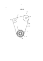
A Figura 1 é um diagrama esquemático de blocos de um sistema de correia de acionamento auxiliar de uma primeira modalidade.Figure 1 is a schematic block diagram of a first mode auxiliary drive belt system.
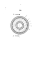
A Figura 2 é uma vista em planta de uma estrutura de polia de acionamento de acordo com a primeira modalidade.Figure 2 is a plan view of a drive pulley structure according to the first embodiment.
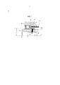
A Figura 3 é uma vista em seção tirada ao longo da linha A-A que contém um eixo de rotação da estrutura de polia de acionamento mostrada na Figura 2.Figure 3 is a sectional view taken along line A-A containing an axis of rotation of the drive pulley structure shown in Figure 2.
A Figura 4 é um diagrama mostrando em detalhes a estrutura de polia de acionamento mostrada na Figura 3.Figure 4 is a diagram showing in detail the drive pulley structure shown in Figure 3.
A Figura 5 é uma vista em planta de uma estrutura de polia de acionamento de acordo com uma segunda modalidade.Figure 5 is a plan view of a drive pulley structure according to a second embodiment.
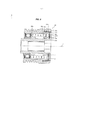
A Figura 6 é uma vista em seção tirada ao longo da linha B-B que contém um eixo e rotação da estrutura de polia de acionamento mostrada na Figura 5.Figure 6 is a sectional view taken along line B-B that contains an axis and rotation of the drive pulley structure shown in Figure 5.
A Figura 7 é um diagrama mostrando com detalhes a estrutura de polia de acionamento mostrada na Figura 6.Figure 7 is a diagram showing in detail the drive pulley structure shown in Figure 6.
A Figura 8 é uma vista em seção que contém um eixo de rotação de uma estrutura de polia de acionamento de acordo com uma terceira modalidade.Figure 8 is a sectional view containing an axis of rotation of a drive pulley structure according to a third embodiment.
Uma primeira modalidade da invenção será agora descrita. Conforme mostrado na Figura 1, esta modalidade descreve um exemplo em que a invenção é aplicada a uma estrutura de polia de acionamento 1 que é usada em um sistema de correia de acionamento auxiliar 100 que aciona uma auxiliar (uma bomba de água ou um alternador) por binário de um eixo de saida 101 de um motor de veiculo motorizado. Observe-se que a estrutura de polia de acionamento 1 é usada para eliminar uma variação em tensão de uma correia de transmissão 106 que é atribuída a uma alteração na rotação do motor.A first embodiment of the invention will now be described. As shown in Figure 1, this modality describes an example where the invention is applied to a drive pulley structure 1 that is used in an auxiliary
A Figura 1 é um diagrama de blocos esquemático do sistema de correia de acionamento auxiliar 100 desta modalidade. Conforme mostrado na Figura 1, o sistema de correia de acionamento auxiliar 100 tem a estrutura de polia de acionamento 1 (uma estrutura de polia) que é conectada ao eixo de saída 101 do motor (um virabrequim de um motor alternativo ou um eixo excêntrico de um motor rotativo), eixos acionados (eixos auxiliares) 102, 103 que estão conectados a auxiliares tais como uma bomba de água e um alternador, uma estrutura de polia acionada 104 que é montada no eixo acionado 102, uma estrutura de polia acionada 107 que é montada o eixo acionado 103 e a correia de transmissão 106 forma uma alça sobre a estrutura de polia de acionamento 1, a estrutura de polia acionada 104 e a estrutura de polia acionada 107. Nesta modalidade, uma correia com nervuras em V tendo uma multiplicidade de nervuras com formato em V que se estendem paralelamente umas às outras ao longo de uma direção longitudinal da correia é usada como a correia de transmissão 106.Figure 1 is a schematic block diagram of the auxiliary
No sistema de correia de acionamento auxiliar 100, quando a estrutura de polia de acionamento 1 é acionada para girar pelo binário de torção do eixo de saída 101, a correia de transmissão 106 é acionada devido à rotação da estrutura de polia de acionamento 1. Consequentemente, a estrutura de polia acionada 104 e a estrutura de polia acionada 107 são acionadas para rodar enquanto a correia de transmissão 106 corre em alça, resultando daí, embora não seja mostrado, que são acionados os auxiliares tais como a bomba de água e o alternador que estão conectados aos eixos acionados 102, 103.In the auxiliary
Em seguida, será descrita com detalhes a estrutura de polia de acionamento 1 que é acionada para girar em função do binário de torção do eixo de saída 101. A Figura 2 é uma vista em planta da estrutura de polia de acionamento 11. Além disso, a Figura 3 é uma vista em seção tirada ao longo da linha A-A que contém um eixo de rotação j da estrutura de polia de acionamento 1 mostrada na Figura 2. Além disso, a Figura 4 é um diagrama mostrando com detalhes a estrutura de polia de acionamento 1 mostrada na Figura 3.Next, the drive pulley structure 1 that is driven to rotate according to the torque of the
Conforme mostrado nas Figuras 2 e 3, a estrutura de polia de acionamento 1 tem um elemento cilíndrico de polia 2 ao redor do qual a correia de transmissão 106 é colocada para se estender, uma estrutura de cubo 3 que é conectada ao eixo de saída 101 e que é prevista no interior do elemento de polia 2, uma mola helicoidal 4 que é fixada à estrutura de cubo 3 em uma extremidade 4a dele, uma parte afusada 5 à qual a outra extremidade 4b da mola helicoidal 4 é fixada e que tem uma superfície circunferencial externa 5a que tem uma superfície arredondada cônica como se fosse parte de um cone cujo eixo é formado pelo eixo de rotação J da estrutura de cubo 3, e um elemento friccionai 6 que é inserido para ficar interposto entre a superfície circunferencial externa 5a da parte afusada 5 que tem a superfície arredondada cônica como se fosse parte de um cone e elemento de polia 2. Adicionalmente, o elemento de polia 2 e a estrutura de cubo 3 são conectados de modo a rodar um em relação ao outro por meio de um mancai de rolamento 9. Além disso, é previsto um mancai deslizante 8 de modo a ficar interposto entre a estrutura de cubo 3 e a parte afusada 5.As shown in Figures 2 and 3, the drive pulley structure 1 has a
O elemento de polia 2 tem um formato cilíndrico, e uma multiplicidade de sulcos de polia 2a são formados em uma circunferência externa do elemento de polia 2 de modo a se estender em uma direção circunferencial sua. Em seguida a correia de transmissão 106 é colocada para se estender ao redor da circunferência externa do elemento de polia 2 em um estado tal, que a multiplicidade de nervuras em formato de v que são previstas na circunferência interna da correia de transmissão 106 estão engatadas com os sulcos de polia 2a correspondentes.The
A estrutura de cubo 3 tem também um formato cilíndrico. O eixo de saída 101 é ajustado dentro de uma porção interior cilíndrica 3a da estrutura de cubo 3 de modo a atravessar a mesma. O eixo de saída 101 e a estrutura de cubo 3 estão conectados entre si por meio de dispositivos de conexão adequados tais como cavilhas para não girar um em relação ao outro. Adicionalmente, como materiais dos quais são fabricados o elemento de polia 2 e a estrutura de cubo 3, para cada um deles podemos citar um material não magnético (um material paramagnético, um material diamagnético ou um material anti-ferromagnético). Mais especificamente como um material não magnético, podemos citar, por exemplo, uma liga de alumínio, uma liga de titânio ou uma resina sintética. Observe-se que o elemento de polia 2 e a estrutura de cubo 3 são conectados entre si de modo a girar um em relação ao outro por mancais de rolamento 9.The cube structure 3 is also cylindrical in shape. The
Conforme mostrado na Figura 3, a parte afusada 5 tem uma seção substancialmente em formato de U. Uma superfície circunferenciais interna da parte afusada 5 tem um formato cilíndrico e uma superfície circunferencial externa sua 5a tem uma superfície arredondada cônica como parte de um cone cujo eixo é constituído pelo eixo de rotação J da estrutura de cubo 3. Neste caso, conforme se pode ver na Figura 4, observando-se em seção, um ângulo θ que é formado por uma extensão 5L da superfície circunferencial externa 5a que é formado na superfície arredondada cônica e o eixo de rotação J é ajustado para se encontrar entre os limites de 1° ou mais e menos de 90°. O mancai deslizante 8 é interposto entre a estrutura de cubo 3 e a parte afusada 5, e isso permite que a estrutura de cubo 3 e a parte afusada 5 girem uma em relação à outra.As shown in Figure 3, the
O elemento friccionai 6 está inserido de modo a ficar interposto entre a superfície circunferencial externa 5a tendo a superfície arredondada cônica e o elemento de polia 2, e o elemento friccionai 6 propriamente dito é fixado ao elemento de polia 2 de modo a não girar. É preferível que o elemento friccionai 6 seja fabricado de um material que tem uma resistência a desgaste e uma resistência a deformação por compressão superiores. Podemos citar metais tais como latão, revestido com latão, bronze e revestido com bronze folheado e resinas tais como poliamida, poliacetal e poliarilato, por exemplo. Adicionalmente, um coeficiente de fricção estática entre a parte afusada 5 e o elemento friccionai 6 é ajustado a um valor que permite que seja gerado um escorregamento relativo entre a parte afusada 5 e o elemento friccionai 6 quando é recebido um binário de torção de entrada desejado. Mais especificamente, o coeficiente de fricção estático é ajustado com base nos materiais selecionados para o elemento friccionai 6 e a parte afusada 5, um modo de um acabamento/configuração da superfície (uma configuração em que são dispostos os recessos e projeções, por exemplo) do elemento friccionai 6 que é colocado encostando-se à parte afusada 5 ou o ângulo θ formado pela extensão 5L da superfície circunferencial externa 5a e o eixo de rotação J.The frictional element 6 is inserted so as to be interposed between the outer
É usada para a mola helicoidal 4 uma mola helicoidal angular em que um elemento linear alongado tem uma seção transversal substancialmente retangular, conforme mostrado na Figura 3, recebe um formato em espiral. Adicionalmente, a mola helicoidal 4 é fixada à estrutura de cubo 3 em uma extremidade 4a sua e é fixada à parte afusada 5 na outra extremidade 4b de tal modo, que a mola helicoidal 4 é comprimida na direção do eixo de rotação J. Em seguida, a parte afusada 5 e o elemento friccionai 6 são colocados em contato com compressão entre si por uma força de restauração P da mola helicoidal 4 deste modo comprimida.An angled helical spring 4 is used for helical spring 4 in which an elongated linear element has a substantially rectangular cross-section, as shown in Figure 3, having a spiral shape. In addition, the coil spring 4 is attached to the hub structure 3 at one end 4a of its own and is attached to the
Mais especificamente, conforme mostrado na Figura 4, a parte afusada 5 é comprimida para contado pela força de restauração P da mola helicoidal. Em seguida a superfície circunferencial externa 5a que tem a superfície arredondada cônica da parte afusada que é assim comprimida para contato é levada a entrar em contato com compressão com o elemento friccionai 6 de modo a comprimir o mesmo pelo arrasto vertical N que é expresso pela seguinte expressão (1) em relação ao ângulo θ que é formado pela extensão 5L da superfície circunferencial externa 5a e pelo eixo de rotação J, observando-se em seção. N = P/senoθ... (1)More specifically, as shown in Figure 4, the
Além disso, um binário de fricção Tf que é gerado entre a superfície circunferencial externa 5a da parte afusada 5 e o elemento friccionai 6 quando a superfície circunferencial externa 5a da parte afusada 5 é colocada em contato com compressão com o elemento friccionai 6 de modo a comprimir o mesmo pelo arrasto vertical N expressão pela expressão (1) acima é expresso pela expressão (2) abaixo: Tf = pxNxr = px P/seno θ x r... (2) em que: p: coeficiente de fricção estática entre a parte afusada 5 e o elemento friccionai 6. r: Raio médio da superfície circunferencial externa 5a tendo a superfície arredondada cônica.In addition, a frictional torque Tf that is generated between the outer
Em seguida, será descrita a função da estrutura de polia de acionamento 1 desta modalidade. Neste caso, a função da estrutura de polia de acionamento 1 será descrita com base na pressuposição de que o eixo de saída 101 gira quando se dá partida ao motor para girar, sendo o binário de torção introduzido na estrutura de polia de acionamento 1 de um lado seu da estrutura de cubo 3 por meio do eixo de saida 101. Pressupondo-se que o binário de torção que é aplicado do lado da estrutura de cubo 3 por meio do eixo de saída 101 seja um binário de torção T de entrada (uma variável), quando a relação entre T e Tf é aproximadamente uma relação expressão pela expressão (3) abaixo, não ocorre nenhum escorregamento sobre uma superfície de contato entre a superfície circunferencial externa 5a da parte afusada 5 e o elemento friccionai 6, e a mola helicoidal 4 sobre uma distorção em uma direção circunferencial para assim absorver o binário de torção T introduzido. T<Tf... (3) Por outro lado, a relação entre R e Tf é aproximadamente uma relação expressão pela expressão (4) abaixo, a mola helicoidal 4 não sofre distorção na direção circunferencial, e ocorre um escorregamento na superfície de contato entre a superfície circunferencial externa 5a da parte afusada 5 e o elemento friccionai 6, sendo o binário de torção T absorvido assim pelo escorregamento. T>Tf... (4).Next, the function of the drive pulley structure 1 of this modality will be described. In this case, the function of the drive pulley structure 1 will be described based on the assumption that the
De acordo com a configuração descrita acima, a parte afusada 5 é comprimida para entrar em contato com a força de restauração P da mola helicoidal 4 e a superfície circunferencial externa 5a tendo a superfície arredondada cônica da parte afusada 5 que é assim comprimida para contato é levada a contato com compressão com o elemento de polia 2 por meio do elemento friccionai 6 para comprimi-lo. Procedendo assim o binário de fricção Tf é gerado entre a superfície circunferencial externa 5a tendo a superfície arredondada cônica da parte afusada 5 e o elemento friccionai 6. Em seguida, quando o binário de torção de entrada T que é maior do que o binário de fricção Tf é introduzido da estrutura de cubo 3, um escorregamento relativo ocorre na superfície onde a superfície circunferencial externa 5a com a superfície arredondada cônica da parte afusada 5 e o elemento friccionai 6 são comprimidos para entrar em contato entre si, de modo que se possa impedir que a mola helicoidal 4 sofra uma distorção até um certo nível ou acima dele. Impedindo-se deste modo que a mola helicoidal 4 sofra distorção até um certo nível ou acima dele, pode ser aumentada a durabilidade da mola helicoidal 4. Além disso, o elemento friccionai 6 e a parte afusada 5 que tem a superfície arredondada cônica que gera o binário de fricção Tf podem ser produzidos com uma boa precisão cortando-se ou moldando-se com um molde, e pode se restringir, portanto, a capacidade de variação do binário de fricção Tf. Além disso, alterando-se livremente o material/desempenho do elemento friccionai 6, pode ser ajustado o binário de fricção Tf desejado, tornando assim possível se ter um projeto com um maior grau de liberdade.According to the configuration described above, the
Adicionalmente, de acordo com a configuração descrita acima, fixando-se o elemento friccionai 6 ao elemento de polia 2 para que ele não gire, permite-se que o elemento friccionai 6 escorregue em relação ã parte afusada 5 somente. Procedendo-se assim, o valor para o binário de fricção Tf que é gerado entre a superfície circunferencial externa 5a com a superfície arredondada cônica da parede externa 5 e o elemento friccionai 6 pode ser determinado levando-se em consideração somente o valor de coeficiente de fricção estática entre o elemento friccionai 6 e a parte afusada 5.In addition, according to the configuration described above, by fixing the frictional element 6 to the
Nesta modalidade, embora a estrutura de polia de acordo com a invenção seja aplicada à estrutura de polia de acionamento 1 que está conectada ao eixo de sarda 101 do motor, a estrutura de polia de acordo com a invenção pode ser aplicada a estruturas de polia acionadas 104, 107 que estão montadas nos eixos acionados (eixos auxiliares) 102, 103 que estão conectados aos auxiliares tais como a bomba de água e o alternado, respectivamente.In this embodiment, although the pulley structure according to the invention is applied to the drive pulley structure 1 which is connected to the
Quando isso ocorre, no sistema de correia de acionamento auxiliar 100, quando a estrutura de polia de acionamento 1 é acionada para girar pelo binário de torção do eixo de saída 101, a correia de transmissão 106 é acionada ela rotação da estrutura de polia de acionamento 1. Em seguida, como a correia de transmissão 106 corre em uma alça, o binário de torção é introduzido de um lado do elemento de polia 2 da estrutura de polia de acionamento 104 ou da estrutura de polia de acionamento 107 ao qual é aplicada a estrutura de polia de acordo com a invenção. Pressupondo-se que o binário de torção introduzido é um binário de torção de entrada T (uma variável), quando a relação entre t e tf é aproximadamente a relação expressa pela expressão (3), não ocorre nenhum escorregamento na superfície de contato entre a superfície circunferencial externa 5a da parte afusada 5 e o elemento friccionai 6, mas a mola helicoidal 4 sofre distorção na direção circunferencial para assim absorver o binário de torção de entrada T. Por outro lado, quando a relação entre T e Tf é aproximadamente igual à relação expressa pela expressão (4) , a mola helicoidal 4 não sofre distorção na direção circunferencial, mas um escorregamento ocorre na superfície de contato entre a superfície circunferencial externa 5a da parte afusada 5 e o elemento friccionai 6 para assim absorver o binário de torção de entrada T.When this occurs, in the auxiliary
Em seguida será descrita a estrutura de polia de acionamento 201 de acordo com uma segunda modalidade principalmente com referência a diferentes configurações da primeira modalidade, omitindo-se a descrição de configurações análogas ás da primeira modalidade. A Figura 5 é uma vista em planta da estrutura de polia 201. Adicionalmente, a Figura 6 é uma vista em seção tirada ao longo da linha B-B que contém um eixo de rotação J da estrutura de polia de acionamento 201 mostrada na Figura 5. Além disso, a Figura 7 é um diagrama mostrando com detalhes a estrutura de polia de acionamento 201 mostrada na Figura 6 .Next, the
Conforme mostrado nas Figuras 5 e 6, a estrutura de polia de acionamento 201 tem um elemento cilíndrico de polia 202 ao redor do qual se estende uma correia de transmissão 106, uma estrutura de cubo 203 que está conectada a um eixo de saída 101 e que é prevista no interior do elemento de polia 202, uma mola helicoidal 204 que está fixada ao elemento de polia 202 em uma extremidade 204b sua, uma parte afusada 205 à qual é fixada a outra extremidade 204a da mola helicoidal 204 e que tem uma superfície circunferencial interna 205a que tem uma superfície arredondada cônica como se fosse uma parte de um cone cujo eixo é constituído pelo eixo de rotação J da estrutura de cubo 203, e um elemento friccionai 206 que é inserido para ficar interposto entre a superfície circunferencial interna 205a da parte afusada 205 que tem a superfície arredondada cônica como se fosse de um cone e a estrutura de cubo 203. Adicionalmente, o elemento de polia 202 e a estrutura de cubo 203 estão conectados de modo a girar um em relação ao outro por meio de um mancai de rolamento 209 e por um mancai deslizante 208.As shown in Figures 5 and 6, the
Conforme mostrado na Figura 6, a parte afusada 205 tem um formato substancialmente cilíndrico. A superfície circunferencial interna 205a da parte afusada 205 tem a superfície arredondada cônica como se fosse parte de um cone cujo eixo constituísse o eixo de rotação J da estrutura de cubo 203. Aqui, conforme mostrado na Figura 7, quando se observa em seção, um ângulo θ que é formado por uma extensão 205L da superfície circunferencial interna 205a que tem uma superfície arredondada cônica e o eixo de rotação J é ajustado para ter entre Io ou mais até menos de 90° .As shown in Figure 6, the
O elemento friccionai 206 é inserido para ficar interposto entre a superfície circunferencial interna 205a que tem a superfície arredondada cônica e a estrutura de cubo 203, e o elemento friccionai 206 propriamente dito está fixado à estrutura de cubo 203 de modo a não girar.The
A mola helicoidal 204 é fixada ao elemento de polia 202 em uma extremidade 204b sua e é fixado à parte afusada 205 na outra extremidade 204a em um estado tal, que a mola helicoidal 204 seja comprimida na direção do eixo de rotação J. Em seguida, a parte afusada 205 e o elemento friccionai 206 são levados a se comprimir em contato entre si por uma força de restauração P da mola helicoidal 204 assim comprimida.The
Mais especificamente, conforme mostrado na Figura 7, a parte afusada 205 é comprimida para contato pela força de restauração P da mola helicoidal. Em seguida a superfície circunferencial interna 205a que tem a superfície arredondada cônica da parte afusada 205 que é assim comprimida para contato e levada a contato com compressão com o elemento friccionai 206 de modo a comprimi-lo por um arrasto vertical N que é expresso pela expressão (1) descrita na primeira modalidade em relação ao ângulo θ que é formado pela extensão 205L da superfície circunferencial interna 205a e pelo eixo de rotação J quando é observada em seção.More specifically, as shown in Figure 7, the blown
Além disso, um binário de fricção Tf que é gerado entre a superfície circunferencial interna 205a da parte afusada 205 e o elemento friccionai 206, quando a superfície circunferencial interna 205a da parte afusada 205 é colocada em contato por compressão com o elemento friccionai 206 de modo a comprimi-lo pelo arrasto vertical N expresso pela expressão (1), é expresso pela expressão (2) que é descrita na primeira modalidade. Na segunda modalidade, p é um coeficiente de fricção estática entre a parte afusada 205 e o elemento friccionai 206 e r é um raio médio da superfície circunferencial interna 205a tendo a superfície arredondada cônica.In addition, a frictional torque Tf that is generated between the inner
Em seguida, será descrita a função da estrutura de polia de acionamento 201 desta modalidade. Aqui, a função da estrutura de polia de acionamento 1 será descrita com base em uma pressuposição de que o eixo de saída 101 gira quando se dá partida ao motor para funcionar, sendo o binário de torção introduzido na estrutura de polia de acionamento 201 de um lado da estrutura de cubo 203 do por meio do eixo de saída 101. Pressupondo-se que o binário de torção que é introduzido do lado da estrutura de cubo por meio do eixo de saída 101 é o binário de torção de entrada T (uma variável) , quando a relação entre T e Tf for aproximadamente uma relação (T<Tf) expressa pela expressão (3) descrita acima, não ocorre nenhum escorregamento em uma superfície de contato entre a superfície circunferencial interna 205a da parte afusada 205 e o elemento friccionai 206, mas a mola helicoidal 204 sofre distorção em uma direção circunferencial para assim absorver o binário de torção de entrada T. Por outro lado, a relação entre T e Tf é aproximadamente uma relação (T>Tf) expressa pela expressão (4) descrita acima, a mola helicoidal 204 não sofre distorção na direção circunferencial, mas um escorregamento ocorre na superfície de contato entre a superfície circunferencial interna 205a da parte afusada 205 e o elemento friccionai 206, sendo o binário de torção de entrada T absorvido pelo escorregamento.Next, the function of the
De acordo com a configuração descrita acima, a parte afusada 205 é comprimida para contato pela força de restauração P da mola helicoidal 204, e a superfície circunferencial interna 205a que tem a superfície arredondada cônica da parte afusada 205 que é assim comprimida. para contato é colocada em contato com compressão com a estrutura de cubo 203 por meio do elemento friccionai 206 para comprimi-lo. Procedendo assim, o binário de fricção Tf é gerado entre a superfície circunferencial interna 205a tendo a superfície arredondada cônica da parte afusada 205 e o elemento friccionai 206. Em seguida, quando o binário de torção T de entrada que é maior do que o binário de fricção Tf é introduzido da estrutura de cubo 203, um escorregamento relativo é produzido na superfície onde a superfície circunferencial interna 205a que tem a superfície arredondada cônica da parte afusada 205 e o elemento friccionai 206 são comprimidos entre si para entrarem em contato, de modo que pode ser impedida até certo nível ou acima dele a distorção da mola helicoidal 204. Impedindo-se deste modo a distorção até certo nível ou acima dele da mola helicoidal 204, pode ser aumentada a durabilidade da mola helicoidal 204. Adicionalmente, o elemento friccionai 206 e a parte afusada 205 que tem a superfície arredondada cônica que gera o binário de fricção Tf podem ser produzidos com uma boa precisão por corte ou moldagem por molde, e pode se restringir, portanto, a capacidade de variação do binário de fricção Tf. Além disso, alterando-se livremente o material/desempenho do elemento friccionai 206, pode ser ajustado um binário de fricção Tf desejado, tornando possível se ter projetos com um maior grau de liberdade.According to the configuration described above, the
Adicionalmente, de acordo com a configuração descrita acima, fixando-se o elemento friccionai 206 à estrutura de cubo 203 de modo que ele não gire, permite-se que o elemento friccionai 206 escorregue somente em relação à parte afusada 205.In addition, according to the configuration described above, fixing the
Em seguida, será descrita uma estrutura de polia acionada 301 (uma estrutura de polia) de acordo com uma terceira modalidade, principalmente em relação a configurações diferentes da primeira modalidade, omitindo a descrição de configurações similares àquelas da primeira modalidade. Conforme mostrado na Figura 8, a estrutura de polia acionada 301 de acordo com a terceira modalidade adota uma configuração em que é incorporada uma construção de embreagem de mola em uma porção em que a mola helicoidal 4 da estrutura de polia de acionamento 1 é a mesma provida na primeira modalidade. Adicionalmente a terceira modalidade será descrita como a estrutura de polia de acionamento 301 de acordo com a presente invenção sendo montada no eixo acionado 102 do sistema de correia de acionamento auxiliar 100 mostrado na Figura 1 para uso como uma estrutura de polia acionada. A Figura 8 é uma vista em seção que contém um eixo de rotação J da estrutura de polia acionada 301.Next, a driven pulley structure 301 (a pulley structure) will be described according to a third modality, mainly in relation to different configurations of the first modality, omitting the description of configurations similar to those of the first modality. As shown in Figure 8, the driven
Na estrutura de polia acionada 301 de acordo com a terceira modalidade, não é adotada a configuração adotada na primeira modalidade em que a mola helicoidal 4 da estrutura de polia de acionamento 1 está fixada diretamente à parte afusada 5 na sua outra extremidade 4b, mas conforme mostrado na Figura 8, sendo adotada uma construção em que a outra extremidade 304b de uma mola helicoidal 304 é elasticamente deformada em uma direção radialmente para fora 0, de modo que a mola helicoidal 3 04 é travada para ser montada em uma parte afusada 3 05 por uma força de restauração F (em uma direção radialmente para dentro) sua. Por outro lado, uma extremidade 304a da mola helicoidal 304 é fixada a uma estrutura de cubo 303.In the driven
Em seguida será descrita a função da estrutura de polia acionada 301 desta modalidade. Em primeiro lugar, será descrita a função da estrutura de polia acionada 301 com base em um caso em que um eixo de saída 101 gira quando se dá partida ao motor e o binário de torção é introduzido na estrutura de polia acionada 301 por meio da estrutura de polia de acionamento 1 e da correia de transmissão 106. Este caso se baseia na pressuposição de que um binário de rotação do elemento de polia 304 excede um binário de rotação da estrutura de cubo 3 03 da estrutura de polia acionada 301 quando se dá partida ao motor para girar.Next, the function of the driven
Como no caso da primeira modalidade, pressupondo-se que o binário que é introduzido na estrutura de polia de acionamento 301 do lado do elemento de polia 302 é um binário de entrada T (uma variável) e que um binário de fricção gerado entre uma superfície circunferencial externa 305a da parte afusada 305 e um elemento friccionai 306 é Tf, quando a relação entre T e Tf é aproximadamente a relação (T<Tf) expressa pela expressão (3) , nenhum escorregamento é produzido na superfície de contato entre a superfície circunferencial externa 305a da parte afusada 305 e o elemento friccionai 306. Adicionalmente, a mola helicoidal 304 tem o diâmetro contraído devido ao contato com a superfície da embreagem 305c da parte afusada 305.As in the case of the first modality, it is assumed that the torque that is introduced in the
Então a mola helicoidal 304 sofre distorção em uma direção circunferencial e é mantida contra a superfície de embreagem 3 0 5c com uma aumento da força de engate de contato com pressão relativa à superfície da embreagem 305c, não ocorrendo nenhum escorregamento, sendo a rotação do elemento de polia 302 transmitida à estrutura de cubo 303. Em seguida, é acionado um auxiliar tal como uma bomba de água ou um alternador que é conectado ao eixo acionado 102 que é montado na estrutura de cubo 303.Then the
Por outro lado, quando a relação entre T e Tf for aproximadamente a relação (T>Tf) expressa pela expressão (4), a mola helicoidal 304 tem o seu diâmetro contraído como resultado do contato com a superfície de embreagem 305c da parte afusada 305 e é mantida contra a superfície da embreagem 3 05c com a força de engate de contato por pressão aumentada em relação à superfície de embreagem 305c, não ocorrendo nenhum escorregamento. No entanto, um escorregamento ocorre na superfície de contato entre a superfície circunferencial externa 305a da parte afusada 305 e o elemento friccionai 306 para assim absorver o binário de entrada T. Absorvendo deste modo o binário de entrada T, a rotação do elemento de polia 3 02 não é transmitida à estrutura de cubo 303, e o elemento de polia 302 pode girar livremente.On the other hand, when the relation between T and Tf is approximately the relation (T> Tf) expressed by expression (4), the
Em seguida, será descrita a função da estrutura de polia acionada 3 01 com base em um caso em que, embora o binário de rotação do elemento de polia 302 esteja reduzido por meio de uma transmissão correia de 106 quando o eixo de saída 101 para de girar como resultado da parada do motor, o binário de rotação da estrutura de cubo 303 excede o binário de rotação do elemento de polia 302 devido à inércia produzida quando o motor gira, isto é, um caso em que o binário é introduzido na estrutura de polia acionada de um lado da estrutura de cubo 303.Next, the function of the driven pulley structure 3 01 will be described based on a case in which, although the rotation torque of the
Pressupondo-se que o binário que é introduzido na estrutura de polia acionada 301 do lado da estrutura de cubo 3 03 seja um binário de entrada T (uma variável) , que um binário de fricção gerado entre a superfície circunferencial externa 305a da parte afusada 305 e o elemento friccionai 306 seja Tf e que um binário de fricção gerado entre a mola helicoidal 304 e a superfície de embreagem 305c seja Ts, quando a relação entre os binários de fricção for tal que T<Ts<Tf, não ocorrerá nenhum escorregamento na superfície de contato entre a superfície circunferencial externa 305a da parte afusada 305 e o elemento friccionai 306. Adicionalmente, a mola helicoidal 304 é mantida contra a superfície de embreagem 305c e não ocorre nenhum escorregamento, sendo a rotação da estrutura de cubo 303 transmitida ao elemento de polia 302.Assuming that the torque that is introduced in the driven
Além disso, quando a relação entre os binários de fricção for tal que Ts<T<Tf, nenhum escorregamento ocorrerá na superfície de contato entre a superfície circunferencial externa 305a da parte afusada 305 e o elemento friccionai 306. Por outro lado, a mola helicoidal 304 tem o diâmetro expandido e a força de engate de contato por pressão relativa ã superfície de embreagem 305c é enfraquecida, o que faz com que ocorra um escorregamento em uma porção de contato entre a mola helicoidal 304 e a superfície de embreagem 305c. Assim, a rotação da estrutura de cubo 303 não é transmitida ao elemento de polia 302, girando assim livremente a estrutura de cubo 303.In addition, when the relationship between the frictional torques is such that Ts <T <Tf, no slipping will occur on the contact surface between the outer
Além disso, quando a relação entre os binários de fricção for tal que Ts<Tf<T, a mola helicoidal 304 terá o diâmetro expandido, e a força de engate de contato por pressão relativa à superfície de embreagem 305c será enfraquecida, o que faz com que ocorra um escorregamento na porção de contato entre a mola helicoidal 304 e a superfície de embreagem 305c. Assim, a rotação da estrutura de cubo 303 não é transmitida para o elemento de polia 302, girando assim a estrutura de cubo 303 livremente.Furthermore, when the relationship between the frictional torques is such that Ts <Tf <T, the
Aqui, na terceira modalidade, a relação entre o binário de fricção Tf que é gerado entre a superfície circunferencial externa 305a da parte afusada 305 e o elemento friccionai 306, e o binário de fricção Ts que é gerado entre a mola helicoidal 304 e a superfície da embreagem 305c é tal, que Ts<Tf. No entanto, ajustando-se livremente os valores dos binários de fricção Ts, Tf (ajustando-se os valore de Ts e Tf a valores diferentes), é possível se determinar, com base na magnitude do binário de entrada T, onde produzir um escorregamento, isto é, ou entre a superfície circunferencial externa 305a da parte afusada 305 e o elemento friccionai 306 ou entre a mola helicoidal 304 e a superfície da embreagem 305c.Here, in the third embodiment, the relationship between the frictional torque Tf that is generated between the outer
Descrevendo-se, por exemplo, um caso em que o binário de rotação da estrutura de cubo 3 03 excede o binário de rotação do elemento de polia 32, devido a inércia produzida quando o motor gira, isto é, um caso em que o binário é introduzido na estrutura de polia de acionamento 301 do lado da estrutura de cubo 303, sendo a relação entre os binários de fricção Tf, Ts tal, que TfcTs, quando os binários de fricção são relacionados com o binário de entrada T de um modo tal, que Tf<T<Ts, a mola helicoidal 304 é mantida contra a superfície da embreagem 305c, não ocorrendo nenhum escorregamento, ao passo que é produzido um escorregamento na superfície de contato entre a superfície circunferencial externa 305a da parte afusada 305 e o elemento friccionai 306, não sendo deste modo a rotação da estrutura de cubo 303 transmitida ao elemento de polia 302 e a estrutura de cubo 303 gira livremente.Describing, for example, a case in which the rotation torque of the hub structure 033 exceeds the rotation torque of the pulley element 32, due to the inertia produced when the motor rotates, that is, a case in which the torque is introduced into the
Além disso, quando os binários de fricção são relacionados com o binário de entrada T, de modo tal, que Tf<Ts<T, é produzido um escorregamento na superfície de contato entre a superfície circunferencial externa 305a da parte afusada 305 e o elemento friccionai 306, não sendo a rotação da estrutura de cubo 303 transmitida ao elemento de polia 302, e a estrutura de cubo 303 gira livremente.In addition, when the frictional torques are related to the input torque T, in such a way that Tf <Ts <T, a slip occurs on the contact surface between the outer
Observe-se que a estrutura de polia acionada 301 funciona do mesmo modo também quando a estrutura de polia acionada 301 é montada no eixo de saída 101 para uso como uma estrutura de polia de acionamento. Neste caso, o eixo de saída 101 gira quando se dá partida ao motor para girar, o binário é introduzido na estrutura de polia acionada 301 do lado da estrutura de cubo 303 por meio do eixo de saída 101, excedendo então o binário de rotação da estrutura de cubo 303 o binário de rotação do elemento de polia 302. Por outro lado, quando o eixo de saída 101 interrompe a rotação devido à interrupção do motor, o binário de rotação do elemento de polia 302 excede o binário de rotação das estruturas de cubo 303 devido ao fato de que a correia de transmissão 106 é acionada pela inércia, sendo assim o binário introduzido na estrutura de polia acionada 301 do lado do elemento de polia 302.Note that the driven
Adicionalmente, a terceira modalidade adota a construção em que a outra extremidade 304b da mola helicoidal 304 é deformada elasticamente na direção radialmente para fora O, de modo que a mola helicoidal 304 é travada para ser montada na parte afusada 3 05 pela sua força de restauração F (na direção radialmente para dentro) . No entanto, a invenção não é limitada a tal construção. Pode ser adotada uma construção em que a outra extremidade 304b da mola helicoidal 304 é elasticamente deformada na direção radialmente para dentro, de modo que a mola helicoidal 3 04 é travada para ser montada na parte afusada 3 05 por uma força de restauração da mesma (na direção radialmente para fora).In addition, the third embodiment adopts the construction in which the
Além disso, na terceira modalidade, uma das extremidades 304a da mola helicoidal 304 está fixada à estrutura de cubo 303. No entanto, tal como a outra extremidade 3 04b da mola helicoidal 3 04, uma das extremidades 304a da mola helicoidal 304 pode ser elasticamente deformada na direção radialmente para fora em vez de ser fixada à estrutura de cubo 303, de modo que uma das extremidades 304a da mola helicoidal 304 é travada sobre a estrutura de cubo 303 por uma força de restauração da mesma (na direção radialmente para dentro).In addition, in the third embodiment, one
Adicionalmente na estrutura de polia acionada 301 de acordo com a terceira modalidade, é adotada a configuração em que o construção de embreagem de mola é incorporada na porção em que a mola helicoidal 4 da estrutura de polia de acionamento 1 é conforme proposto na primeira modalidade. No entanto pode ser adotada uma configuração em que a construção de embreagem de mola é incorporada na porção em que é provida a mola helicoidal 204 da estrutura de polia de acionamento 201 como na segunda modalidade. Quando isso ocorre, a outra extremidade 204a da mola helicoidal 204 é elasticamente deformada na direção radialmente para fora, de modo que a mola helicoidal 2 04 é travada na parte afusada 205 por uma força de restauração da mesma (na direção radialmente para dentro). Adicionalmente uma das extremidades 204b da mola helicoidal 204 pode ser fixada ao elemento de polia 202 ou pode ser elasticamente deformada na direção radialmente para fora (para dentro), tal como a outra extremidade 204a da mola helicoidal 204, de modo que uma extremidade 204b das mola helicoidal 204 é travada no elemento de polia 202 por uma força de restauração da mesma (na direção radialmente para dentro [para fora]).In addition to the driven
De acordo com a configuração descrita acima, é possível se gerar os dois binários de fricção que são o binário de fricção Tf que é gerado entre a superfície circunferencial externa 305a que tem uma superfície arredondada cônica da parte afusada 305 e o elemento friccionai 306 e o binário de fricção Ts que é gerado entre a outra extremidade 304b da mola helicoidal 304 e a superfície de embreagem 305c da parte afusada 305. Gerando- se as duas forças friccionais do modo descrito acima, por exemplo, quando a estrutura de polia acionada 301 de acordo com a invenção é montada no eixo acionado 102 para ser usada como a estrutura de polia acionada, com o binário de entrada T introduzido do lado do elemento de polia 302, caso o binário de entrada T for maior do que o binário de fricção Tf que é gerado entre a superfície circunferencial externa 305a da parte afusada 205 e o elemento friccionai 306, o binário de entrada T pode ser absorvido por produzir um escorregamento na superfície de contato entre a superfície circunferencial externa 305a da parte afusada 305 e o elemento friccionai 306. Por outro lado, com o binário de entrada T introduzido da estrutura de cubo 303 do lado, no caso em que os binários de fricção respectivos estão relacionados ao binário de entrada T, de modo que Ts<T<Tf, não se produz nenhum escorregamento na superfície de contato entre a superfície circunferencial externa 305a da parte afusada 305 e o elemento friccionai 306, mas é produzido um escorregamento na mola helicoidal 304 na porção de contato entre a mola helicoidal 304 e a superfície de embreagem 305c. Assim, a rotação da estrutura de cubo 3 03 não é transmitida ao elemento de polia 3 02, permitindo-se assim que a estrutura de cubo 303 gire livremente. Além disso, caso os binários de fricção respectivos estão relacionados ao binário de entrada T de modo tal que Ts<Tf<T, é produzido um escorregamento na mola helicoidal 304 na porção de contato entre a mola helicoidal 304 e a superfície de embreagem 305c, e a rotação da estrutura de cubo 3 03 não é transmitida ao elemento de polia 3 02, sendo permitido assim que a estrutura de cubo 303 gire livremente. Adotando-se esta configuração, é possível se ter um projeto com um maior grau de liberdade, alterando-se livremente os valores do binário de fricção Ts que é gerado entre a outra extremidade 3 04b da mola helicoidal 304 e a superfície de embreagem 305c da parte afusada 305, e o elemento friccionai Tf que é gerado entre a superfície circunferencial externa 305a que tem uma superfície arredondada cônica da parte afusada 305 e o elemento friccionai 306.According to the configuration described above, it is possible to generate the two frictional torques which are the frictional torque Tf which is generated between the outer
Além disso, ajustando-se livremente os valores dos binários de fricção Ts, Tf (ajustando-se os valores de Ts e Tf a valores diferentes), é possível se determinas com base na magnitude do binário de entrada T onde produzir um escorregamento, isto, ou entre a superfície circunferencial externa 305a da parte afusada 305 e o elemento friccionai 306 ou entre a mola helicoidal 304 e a superfície da embreagem 305c.In addition, by freely adjusting the values of the frictional torques Ts, Tf (by adjusting the values of Ts and Tf to different values), it is possible to determine based on the magnitude of the input torque T where to produce a slip, this , or between the outer
Assim, embora tenham sido descritas acima modalidades da invenção, a invenção não é limitada ás modalidades descritas acima, mas pode ser implementada introduzindo-se diversas alterações sem se desviar do âmbito das reivindicações a serem descritas abaixo.Thus, although modalities of the invention have been described above, the invention is not limited to the modalities described above, but can be implemented by introducing several changes without departing from the scope of the claims to be described below.
Embora o pedido de patente tenha sido descrito com detalhes e com referência a modalidades específicas, é óbvio aos versados na técnica à qual a invenção pertence que diversas alterações e modificações podem ser introduzidas nela sem que haja desvio do espírito e âmbito da invenção.Although the patent application has been described in detail and with reference to specific modalities, it is obvious to those skilled in the art to which the invention belongs that several changes and modifications can be made to it without deviating from the spirit and scope of the invention.
Este pedido de patente é baseado no Pedido de Patente Japonesa (No. 2010-193935) depositado em 31 de agosto de 2010, cujo conteúdo é incorporado ao presente documento a título de referência. DESCRIÇÃO DOS NÚMEROS DE REFERÊNCIA

Claims (6)
Applications Claiming Priority (3)
| Application Number | Priority Date | Filing Date | Title |
|---|---|---|---|
| JP2010-193935 | 2010-08-31 | ||
| JP2010193935A JP5515084B2 (en) | 2010-08-31 | 2010-08-31 | Pulley structure |
| PCT/JP2011/069669 WO2012029815A1 (en) | 2010-08-31 | 2011-08-30 | Pulley structure |
Publications (2)
| Publication Number | Publication Date |
|---|---|
| BR112013004876A2 BR112013004876A2 (en) | 2016-05-03 |
| BR112013004876B1 true BR112013004876B1 (en) | 2020-09-29 |
Family
ID=45772895
Family Applications (1)
| Application Number | Title | Priority Date | Filing Date |
|---|---|---|---|
| BR112013004876-0A BR112013004876B1 (en) | 2010-08-31 | 2011-08-30 | PULLEY STRUCTURE |
Country Status (7)
| Country | Link |
|---|---|
| US (1) | US9638308B2 (en) |
| EP (1) | EP2626595B1 (en) |
| JP (1) | JP5515084B2 (en) |
| CN (1) | CN103080608B (en) |
| BR (1) | BR112013004876B1 (en) |
| CA (1) | CA2808060C (en) |
| WO (1) | WO2012029815A1 (en) |
Families Citing this family (21)
| Publication number | Priority date | Publication date | Assignee | Title |
|---|---|---|---|---|
| US8784244B2 (en) * | 2008-04-30 | 2014-07-22 | Dayco Ip Holdings, Llc | Pulley with asymmetric torque-sensitive clutching |
| US8888622B2 (en) * | 2012-06-04 | 2014-11-18 | The Gates Corporation | Isolator decoupler |
| CN102758860B (en) * | 2012-07-27 | 2015-04-15 | 重庆大易用机械有限公司 | Conical-surface friction type overrunning clutch |
| US11236812B2 (en) * | 2012-09-10 | 2022-02-01 | Zen S/A Industria Metalurgica | Decoupler with one-way clutch and fail-safe system |
| BR102012022803B1 (en) * | 2012-09-10 | 2017-05-02 | Zen S/A Indústria Metalúrgica | decoupler with freewheel system and vibration damping |
| KR101500138B1 (en) * | 2013-09-10 | 2015-03-06 | 현대자동차주식회사 | Decoupling device of crank pully |
| EP3052825B1 (en) | 2013-10-01 | 2019-01-30 | Litens Automotive Partnership | Decoupler with controlled damping |
| US9169914B2 (en) * | 2014-03-07 | 2015-10-27 | Gates Corporation | Isolating decoupler |
| US9341254B2 (en) * | 2014-08-08 | 2016-05-17 | Gates Corporation | Isolating pulley |
| US9759274B2 (en) | 2014-08-18 | 2017-09-12 | Gates Corporation | Accessory tuning device with spring lock |
| BR112017004585B1 (en) | 2014-09-10 | 2022-10-11 | Litens Automotive Partnership | DECOUPLER, ACCESSORY DRIVE ARRANGEMENT, AND POWER TRANSFER DEVICE. |
| US9291253B1 (en) * | 2015-03-24 | 2016-03-22 | Gates Corporation | Isolating decoupler |
| US9784357B2 (en) * | 2015-04-27 | 2017-10-10 | Ningbo Yangtong Automobile Parts Co., Ltd. | Overrunning alternator damping pulley |
| KR101724471B1 (en) * | 2015-05-26 | 2017-04-18 | 현대자동차 주식회사 | Alternator unit having vibration reducing damper |
| US9618099B2 (en) | 2015-07-13 | 2017-04-11 | Gates Corporation | Tensioner with secondary damping |
| CN105715757A (en) * | 2016-04-12 | 2016-06-29 | 无锡凯能光伏设备有限公司 | Adjustable rotary drive device with safety clutch |
| JP6511085B2 (en) * | 2016-04-28 | 2019-05-15 | 三ツ星ベルト株式会社 | Pulley structure |
| FR3053394B1 (en) * | 2016-06-30 | 2019-08-09 | Hutchinson | DECOUPLING PULLEY WITH DEPARTURE CLUTCH |
| EP3601828B1 (en) | 2017-03-28 | 2022-05-18 | Litens Automotive Partnership | Isolation device with selected angle between spring stop and damping member |
| JP6950954B2 (en) * | 2017-12-22 | 2021-10-13 | 国立大学法人金沢大学 | Liquid filling method, SIMM probe manufacturing method, SIMM probe and SIMM |
| US11549558B2 (en) | 2018-08-01 | 2023-01-10 | Gates Corporation | Isolator decoupler |
Family Cites Families (11)
| Publication number | Priority date | Publication date | Assignee | Title |
|---|---|---|---|---|
| US5139463A (en) | 1991-06-05 | 1992-08-18 | Litens Automotive Partnership | Serpentine drive with coil spring alternator connection |
| JP4013384B2 (en) * | 1999-02-05 | 2007-11-28 | 株式会社ジェイテクト | Pulley unit with one-way clutch |
| DE10012233A1 (en) * | 2000-03-14 | 2001-09-20 | Schaeffler Waelzlager Ohg | Automotive pulley drive wheel with friction slip clutch and helical spring on a hub |
| JP2003322174A (en) | 2002-05-07 | 2003-11-14 | Ntn Corp | Spring clutch |
| CA2547383C (en) * | 2003-12-09 | 2013-08-13 | Litens Automotive Partnership | Spring travel limiter for overrunning alternator decoupler |
| JP2006038183A (en) * | 2004-07-30 | 2006-02-09 | Koyo Seiko Co Ltd | Power transmission |
| JP5026687B2 (en) * | 2004-12-02 | 2012-09-12 | 三ツ星ベルト株式会社 | Pulley structure |
| EP1844245B1 (en) * | 2005-02-03 | 2013-04-24 | Litens Automotive Partnership | Torque limited decoupler |
| EP1754914A1 (en) | 2005-08-19 | 2007-02-21 | Industrias Cántabras de Torneado S.R.L. | Alternator pulley |
| JP4957264B2 (en) * | 2007-01-24 | 2012-06-20 | 株式会社ジェイテクト | Pulley unit |
| US8529387B2 (en) * | 2008-04-30 | 2013-09-10 | Dayco Ip Holdings, Llc | Pulley with asymmetric torque-sensitive clutching |
-
2010
- 2010-08-31 JP JP2010193935A patent/JP5515084B2/en active Active
-
2011
- 2011-08-30 EP EP11821830.4A patent/EP2626595B1/en active Active
- 2011-08-30 CN CN201180042045.XA patent/CN103080608B/en active Active
- 2011-08-30 BR BR112013004876-0A patent/BR112013004876B1/en active IP Right Grant
- 2011-08-30 WO PCT/JP2011/069669 patent/WO2012029815A1/en active Application Filing
- 2011-08-30 CA CA2808060A patent/CA2808060C/en active Active
- 2011-08-30 US US13/817,967 patent/US9638308B2/en active Active
Also Published As
| Publication number | Publication date |
|---|---|
| US9638308B2 (en) | 2017-05-02 |
| CN103080608A (en) | 2013-05-01 |
| CA2808060C (en) | 2018-05-22 |
| EP2626595A4 (en) | 2014-02-26 |
| US20130150191A1 (en) | 2013-06-13 |
| CA2808060A1 (en) | 2012-03-08 |
| JP5515084B2 (en) | 2014-06-11 |
| BR112013004876A2 (en) | 2016-05-03 |
| EP2626595A1 (en) | 2013-08-14 |
| CN103080608B (en) | 2016-01-20 |
| EP2626595B1 (en) | 2019-08-07 |
| JP2012052576A (en) | 2012-03-15 |
| WO2012029815A1 (en) | 2012-03-08 |
Similar Documents
| Publication | Publication Date | Title |
|---|---|---|
| BR112013004876B1 (en) | PULLEY STRUCTURE | |
| BR112013012483A2 (en) | insulating decoupler | |
| JP2006177548A (en) | Pulley for power transmission member, separate starter-alternator fitted with such pulley, and engine drive system | |
| US3485062A (en) | Flexible coupling | |
| KR20130108516A (en) | Isolation pulley with overrunning and vibration damping capabilities | |
| CN109312789A (en) | Belt pulley decoupler | |
| KR101834815B1 (en) | Dual-type wave gear device | |
| KR101918011B1 (en) | Dual-type wave gear device | |
| ES2286004T3 (en) | MULTIDISCO CLUTCH WITH HELICOIDAL MEDIA TO DYNAMICALLY ADJUST THE AXIAL COMPRESSION LOAD ON THE DISCS. | |
| JP5429119B2 (en) | Planetary gear set | |
| US20100258395A1 (en) | Braking device, in particular for rolling curtains, shutters, mosquito nets and the like | |
| US2566575A (en) | Coupling | |
| US2196716A (en) | Torque coupling | |
| US1147620A (en) | Shaft-coupling. | |
| JP6895319B2 (en) | Tortional damper | |
| US1488740A (en) | Resilinet universal joint for power transmission | |
| US10883591B2 (en) | Sliding contact-type wave generator, strain wave gearing, and wave-generating method | |
| US20100181878A1 (en) | Power output device and power enhancement member | |
| US1440847A (en) | Flexible coupling | |
| JP2008202739A (en) | Pulley structure | |
| US20210293285A1 (en) | Torque limiting coupler for an electric motor shaft | |
| ITTO20000920A1 (en) | DRIVING GROUP FOR AN ALTERNATOR OF A MOTOR VEHICLE. | |
| US1400368A (en) | Shock-absorber for drive-shafts | |
| US3918652A (en) | Core chucks | |
| JP3889819B2 (en) | Torque fluctuation absorbing damper |
Legal Events
| Date | Code | Title | Description |
|---|---|---|---|
| B06F | Objections, documents and/or translations needed after an examination request according [chapter 6.6 patent gazette] | ||
| B06T | Formal requirements before examination [chapter 6.20 patent gazette] | ||
| B09A | Decision: intention to grant [chapter 9.1 patent gazette] | ||
| B16A | Patent or certificate of addition of invention granted [chapter 16.1 patent gazette] |
Free format text: PRAZO DE VALIDADE: 20 (VINTE) ANOS CONTADOS A PARTIR DE 30/08/2011, OBSERVADAS AS CONDICOES LEGAIS. |