WO2012029469A1 - 電気掃除機 - Google Patents
電気掃除機 Download PDFInfo
- Publication number
- WO2012029469A1 WO2012029469A1 PCT/JP2011/067297 JP2011067297W WO2012029469A1 WO 2012029469 A1 WO2012029469 A1 WO 2012029469A1 JP 2011067297 W JP2011067297 W JP 2011067297W WO 2012029469 A1 WO2012029469 A1 WO 2012029469A1
- Authority
- WO
- WIPO (PCT)
- Prior art keywords
- dust
- filter
- sliding member
- vacuum cleaner
- rotating body
- Prior art date
- Legal status (The legal status is an assumption and is not a legal conclusion. Google has not performed a legal analysis and makes no representation as to the accuracy of the status listed.)
- Ceased
Links
Images



Classifications
-
- A—HUMAN NECESSITIES
- A47—FURNITURE; DOMESTIC ARTICLES OR APPLIANCES; COFFEE MILLS; SPICE MILLS; SUCTION CLEANERS IN GENERAL
- A47L—DOMESTIC WASHING OR CLEANING; SUCTION CLEANERS IN GENERAL
- A47L9/00—Details or accessories of suction cleaners, e.g. mechanical means for controlling the suction or for effecting pulsating action; Storing devices specially adapted to suction cleaners or parts thereof; Carrying-vehicles specially adapted for suction cleaners
- A47L9/20—Means for cleaning filters
-
- A—HUMAN NECESSITIES
- A47—FURNITURE; DOMESTIC ARTICLES OR APPLIANCES; COFFEE MILLS; SPICE MILLS; SUCTION CLEANERS IN GENERAL
- A47L—DOMESTIC WASHING OR CLEANING; SUCTION CLEANERS IN GENERAL
- A47L9/00—Details or accessories of suction cleaners, e.g. mechanical means for controlling the suction or for effecting pulsating action; Storing devices specially adapted to suction cleaners or parts thereof; Carrying-vehicles specially adapted for suction cleaners
- A47L9/10—Filters; Dust separators; Dust removal; Automatic exchange of filters
- A47L9/16—Arrangement or disposition of cyclones or other devices with centrifugal action
- A47L9/1608—Cyclonic chamber constructions
-
- A—HUMAN NECESSITIES
- A47—FURNITURE; DOMESTIC ARTICLES OR APPLIANCES; COFFEE MILLS; SPICE MILLS; SUCTION CLEANERS IN GENERAL
- A47L—DOMESTIC WASHING OR CLEANING; SUCTION CLEANERS IN GENERAL
- A47L9/00—Details or accessories of suction cleaners, e.g. mechanical means for controlling the suction or for effecting pulsating action; Storing devices specially adapted to suction cleaners or parts thereof; Carrying-vehicles specially adapted for suction cleaners
- A47L9/10—Filters; Dust separators; Dust removal; Automatic exchange of filters
- A47L9/16—Arrangement or disposition of cyclones or other devices with centrifugal action
- A47L9/1683—Dust collecting chambers; Dust collecting receptacles
-
- A—HUMAN NECESSITIES
- A47—FURNITURE; DOMESTIC ARTICLES OR APPLIANCES; COFFEE MILLS; SPICE MILLS; SUCTION CLEANERS IN GENERAL
- A47L—DOMESTIC WASHING OR CLEANING; SUCTION CLEANERS IN GENERAL
- A47L9/00—Details or accessories of suction cleaners, e.g. mechanical means for controlling the suction or for effecting pulsating action; Storing devices specially adapted to suction cleaners or parts thereof; Carrying-vehicles specially adapted for suction cleaners
- A47L9/10—Filters; Dust separators; Dust removal; Automatic exchange of filters
- A47L9/16—Arrangement or disposition of cyclones or other devices with centrifugal action
- A47L9/1691—Mounting or coupling means for cyclonic chamber or dust receptacles
Definitions
- the present invention relates to a vacuum cleaner provided with a filter dust removing device.
- Patent Document 1 A conventional vacuum cleaner is disclosed in Patent Document 1.
- This electric vacuum cleaner has a main body with an electric blower.
- a cyclone type dust collecting part is arranged in front of the electric blower in the main body part.
- the dust collecting unit includes a bottomed cylindrical dust collecting container having a circular cross section having an opening surface on the upper surface.
- the peripheral surface of the dust collecting container is provided with an inflow port through which an airflow containing dust flows in a circumferential tangential direction.
- a swirling airflow is formed in the dust collecting container by the air flowing from the inlet.
- a circular filter in plan view held by a filter holding part that is detachable from the dust collecting container is disposed on the opening surface of the upper surface of the dust collecting container.
- the filter holding portion has a receiving surface formed of a conical surface covering the lower side of the filter, and an inner cylinder extending downward from the receiving surface is integrally provided.
- the inner cylinder is arranged on the central axis of the dust collecting container, and an outlet port through which airflow flows out from the dust collecting container opens on the peripheral surface of the inner cylinder.
- a cover part that forms the exterior of the main body is provided above the filter.
- the cover part is provided detachably with respect to the filter holding part, and a grip part to be gripped by the user is provided on the upper surface.
- a communication path that communicates between the filter and the electric blower is formed on the inner surface of the cover part, and a dust collection part exhaust port that is an end surface of the communication path opens on the back surface of the cover part.
- a dust removing device is provided in the filter holding part.
- the dust removing device includes a rotatable rotating body provided integrally with the filter, and the cover portion is provided with a flexible dust removing member that projects downward from the upper surface of the filter.
- the rotating body rotates integrally with the filter by the drive motor, and the filter is beaten by the dust removing member.
- a flexible sliding member that rotates and slides on the receiving surface is provided at the lower part of the rotating body.
- the dust on the surface to be cleaned is sucked together with the air from the suction port body by driving the electric blower.
- the air sucked from the suction port body flows into the dust collecting container of the dust collecting portion from the inlet through the extension pipe and the connecting hose.
- the air flowing into the dust collecting container swirls in the dust collecting container, and large dust is separated by the centrifugal force and accumulated in the dust collecting container.
- the air stream from which large dust has been removed flows through the inner cylinder through the outlet, and fine dust is collected by the filter.
- the airflow from which fine dust has been removed flows through the communication path, and flows out of the dust collector through the dust collector exhaust port.
- the air that flows out from the dust collecting section passes through the electric blower and is exhausted to the outside. Thereby, the surface to be cleaned can be cleaned.
- the dust accumulated in the dust collecting container can be discarded.
- the dust removing member strikes the filter, and the dust collected by the filter falls onto the receiving surface.
- the sliding member rotates and slides on the receiving surface, and dust on the receiving surface formed of a conical surface slides down to the inner cylinder.
- JP 2009-112506 A page 3 to page 12, FIG. 2
- the receiving surface disposed below the filter is formed by a conical surface to allow dust to slide down on the inner cylinder. For this reason, there existed a problem which a dust collection part became large in an axial direction and caused the enlargement of a vacuum cleaner.
- An object of the present invention is to provide a vacuum cleaner that can be miniaturized.
- the present invention comprises a dust collecting container which is formed in a bottomed cylindrical shape having a circular cross section with an opening surface at one end surface and an airflow inlet is provided on the peripheral surface, and a dust collecting container disposed on the opening surface.
- a dust collecting container Formed by a filter, a dust removing member that taps the filter to remove dust, and a plane perpendicular to the axial direction disposed below the filter and receiving dust that has fallen from the filter by the dust removing member
- an inner cylinder that is open to the receiving surface and extends downward and is coaxially arranged with the dust collecting container and has an air outlet for the air flowing out of the dust collecting container on the peripheral surface, and rotates on the receiving surface.
- a flexible sliding member formed in a spiral shape that slides and guides dust to the inner cylinder.
- an air flow including dust flows into the dust collecting container from the inflow port by driving the electric blower, and flows out through the outflow port provided in the inner cylinder.
- large dust accumulates in the dust collecting container.
- Fine dust is collected in the airflow flowing through the inner cylinder by a filter disposed on the opening surface.
- the airflow that has passed through the filter passes through the electric blower and is exhausted.
- the dust removing member strikes the filter by a predetermined operation, the filter is removed, and the dust collected by the filter falls onto a flat receiving surface.
- the spiral sliding member rotates and slides on the receiving surface, and the dust dropped on the receiving surface is guided to the inner cylinder arranged on the inner peripheral side and collected in the dust collecting container.
- a rotating body that is rotatably supported by a shaft portion that passes through the filter and that is provided with the sliding member at a lower portion, and an upper surface of the rotating body.
- a handle for rotating the rotating body, the dust removing member and the filter collide with each other by the rotation of the rotating body, and the dust on the receiving surface is guided to the inner peripheral side of the sliding member. The rotation direction of the handle is restricted.
- the rotating body is rotated by the operation of the handle, the dust removing member strikes the filter, and the sliding member rotates and slides on the receiving surface.
- the rotation direction of the handle is restricted to one direction so that the rotating body rotates in a direction in which dust is guided to the inner peripheral side of the sliding member that slides on the receiving surface.
- the filter may rotate integrally with the rotating body and collide with the dust removing member, or the dust removing member may rotate integrally with the rotating body and collide with the filter.
- a rail portion that extends in a radial direction from the shaft portion and guides the handle is provided, the rail portion being perpendicular to a rotation axis of the rotating body.
- the outer peripheral side is curved toward the front in the rotational direction of the handle.
- the handle is moved to a position away from the shaft portion by the guide of the rail portion, and the rotating body is rotated.
- a circumferential load is applied to the handle on the side where the center of curvature of the curved rail portion is arranged, and the rotating body is rotated, so that the movement of the handle toward the inner periphery is suppressed.
- an angle between a diameter of the outer peripheral end of the sliding member and a tangent is set to approximately 90 °.
- the present invention is characterized in that, in the vacuum cleaner having the above configuration, an angle between a diameter and a tangent of an arbitrary point between the outer peripheral end and the inner peripheral end of the sliding member is set to 45 ° to 90 °. Yes.
- the present invention is characterized in that, in the vacuum cleaner having the above-described configuration, a central angle between the outer peripheral end and the inner peripheral end of the sliding member is formed to be 180 ° or more.
- the receiving surface disposed below the filter is formed by a plane perpendicular to the axial direction, and the flexible sliding member that rotates and slides on the receiving surface is formed in a spiral shape that guides dust to the inner cylinder. Therefore, the dust collection part can be made small in the axial direction, and the dust dropped from the filter can be collected in the dust collection container. Therefore, it is possible to reduce the size of the electric vacuum cleaner.
- the perspective view which shows the vacuum cleaner of embodiment of this invention Side surface sectional drawing which shows the main-body part of the vacuum cleaner of embodiment of this invention Side surface sectional drawing which shows the state which removed the dust collecting part of the main-body part of the vacuum cleaner of embodiment of this invention.
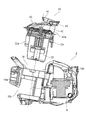
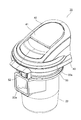
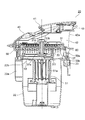
- the perspective view which shows the dust collection part of the vacuum cleaner of embodiment of this invention Side surface sectional drawing which shows the dust collection part of the vacuum cleaner of embodiment of this invention
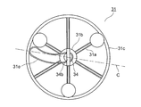
- the perspective view which shows the state which opened the cover part of the dust collection part of the vacuum cleaner of embodiment of this invention The top view which shows the state which has arranged the handle
- FIG. 1 is a perspective view showing a vacuum cleaner according to an embodiment.
- the vacuum cleaner 1 includes a main body 2 that houses an electric blower 6 (see FIG. 2).
- a power cord 8 that can be pulled out and stored is provided on the back surface of the main body 2.
- the power cord 8 has a power plug 9 at its tip, and is supplied to the main unit 2 by being inserted into a commercial power outlet.
- a flexible connection hose 3 is connected to the front surface of the main body 2, and an extension pipe 4 is connected to the tip of the connection hose 3.
- a suction port body 5 having a suction port (not shown) facing the floor surface is provided at the tip of the extension pipe 4.
- the extension pipe 4 is provided with a pipe gripping portion 13 and an operation portion 14. The user operates the operation unit 14 to perform the cleaning operation, grips the pipe gripping part 13, and moves the suction port body 5.
- FIG. 2 shows a side sectional view of the main body 2.
- the main body 2 is covered with a main body cover 10, and the electric blower 6 is arranged at the rear.
- a connection port 10a for connecting the connection hose 3 (see FIG. 1) is opened on the front surface of the main body cover 10, and an exhaust port 10b is opened on the back surface.
- a dust collection chamber 19 (see FIG. 3) is provided in front of the electric blower 6, and a cyclone type dust collection section 20 is disposed in the dust collection chamber 19.
- the dust collection container 22 of the dust collection unit 20 is made of a transparent resin, and a window 10 c that allows the inside of the dust collection container 22 to be visually recognized is provided in the main body cover 10.
- the dust collection unit 20 is provided with an inlet 22a communicating with the connection port 10a and a dust collection unit exhaust port 42a through which airflow from which dust is removed flows.
- the dust collector exhaust port 42 a and the electric blower 6 are connected by a duct 15.
- a cover part 40 that continuously forms the exterior of the main body part 2 is arranged.
- a rotatable gripping part 41 pivotally supported at the rear part is provided on the upper surface of the cover part 40, and an engaging part 43 that engages with the main body cover 10 is provided at the upper rear of the cover part 40.
- the engaging portion 43 moves forward and backward by the rotation of the grip portion 41.
- the dust collecting part 20 is attached to the main body part 2 by hooking the front part of the cover part 40 on the main body cover 10 and engaging the rear engaging part 43.
- the engaging part 43 moves forward and is disengaged from the main body cover 10, and the dust collecting part 20 can be detached from the main body 2 upward as shown in FIG. Thereby, the dust collected by the dust collection part 20 can be discarded.
- the dust collection unit 20 includes a cover unit 40, a filter holding unit 50, and a dust collection container 22.
- the dust collection container 22 is made of a transparent resin, and is formed in a bottomed cylindrical shape having a substantially circular cross section with an opening surface 22b on the upper surface.
- An inlet 22a that communicates with the connection port 10a (see FIG. 2) and into which airflow from the connection hose 3 (see FIG. 1) flows is provided on the peripheral surface of the front portion of the dust collecting container 22.
- the air current flows into the dust collecting container 22 in the circumferential tangential direction through the inlet 22 a, and a swirling air current is formed in the dust collecting container 22.
- a cyclone type dust collector is formed, and the dust contained in the airflow is separated by centrifugal force.
- a clip 23 that is rotatable about a horizontal axis is provided on the peripheral surface of the rear portion of the dust collecting container 22.
- the filter holding unit 50 holds a circular filter 37 in plan view.
- the filter 37 is formed of a pleated filter, and is formed by bending so that a crest and a trough are continuous in a direction perpendicular to the axial direction. Thereby, the filter 37 has a wide collection area, covers the opening surface 22b of the dust collection container 22, and collects dust.
- the filter holding part 50 has an annular part 50 a along the peripheral surface of the circular filter 37 in plan view, and is detachably provided to the dust collecting container 22.
- the filter holding unit 50 is provided with a receiving surface 50b disposed below the filter 37.
- the receiving surface 50b is formed by a plane perpendicular to the axial direction, and is provided with an inner cylinder 51 that extends downward from the periphery of an opening 50c (see FIG. 9) that opens in the center.
- the inner cylinder 51 is arranged coaxially with the dust collecting container 22, and an air outlet 51 a for flowing out of the dust collecting container 22 is provided on the peripheral surface.
- the filter holding unit 50 is provided with a dust removing device 30 (see FIG. 6) that removes dust collected by the filter 37.
- the upper surface of the cover part 40 is formed as an inclined surface with the front side lowered, and a communication path 42 for communicating the filter 37 and the duct 15 (see FIG. 2) is formed inside the cover part 40.
- a dust collection portion exhaust port 42 a that is an end surface of the communication passage 42 opens.
- the cover part 40 is pivotally supported on the filter holding part 50 by a hinge part 60 provided on the back surface, and opens and closes the upper side of the filter 37.
- FIG. 6 is a perspective view showing a state where the cover part 40 of the dust collecting part 20 is opened.
- a hook 46 and a pressing member 45 are provided on the lower surface of the front portion of the cover portion 40.
- the hook 46 is provided integrally with the cover portion 40 and is formed so as to be elastically deformable in the circumferential direction.
- the pressing member 45 protrudes from the lower surface of the cover portion 40 and is provided so as to be movable up and down, and is biased downward.
- the annular portion 50a of the filter holding portion 50 is provided with a contact portion 54 and a lock member 52 at a front portion opposed to the hinge portion 60 in the radial direction.
- the abutting portion 54 abuts on the pressing member 45 and is pressed by the urging force of the pressing member 45.
- the lock member 52 is movably provided in the circumferential direction and is urged in one direction (the direction of the arrow E1) by a compression spring (not shown). The lock member 52 engages with the hook 46 to lock the closed state of the cover unit 40 and the filter holding unit 50.
- the filter holder 50 is provided with a dust removing device 30 that removes the filter 37.
- the dust removing device 30 includes a rotating body 31 made of a resin molded product having a circular shape in plan view.
- the rotating body 31 is provided with a shaft portion 31b having a shaft 31d (see FIG. 5) extending downward at the center.
- the shaft 31d is fitted into a fitting hole 37a (see FIG. 5) penetrating the filter 37, and the rotating body 31 is rotatably supported with respect to the filter 37 via the shaft portion 31b.
- the rotary body 31 is provided with a circular annular portion 31 c disposed above the periphery of the filter 37.
- the annular portion 31c is supported by a plurality of arm portions 31a extending radially from the shaft portion 31b, and an air current flows through each arm portion 31a.
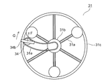
- a rail portion 31e that is curved with respect to a center line C (see FIG. 7) perpendicular to the rotation axis is formed between the shaft portion 31b and the annular portion 31c of the rotating body 31.
- An engaging portion 34a provided at the lower portion of the handle 34 is engaged with the rail portion 31e, and the handle 34 is rotatably held with respect to the rail portion 31e.
- the handle 34 is provided with a protruding portion 34b that protrudes upward from the engaging portion 34a and is held by a user's finger. The handle 34 can be moved in the radial direction of the rotating body 31 by holding the protruding portion 34b and guiding the rail portion 31e.
- FIG. 7 shows a top view of the rotating body 31.
- the handle 34 when the handle 34 is disposed at a position overlapping the shaft portion 31b, the handle 34 is retracted from the opening between the arm portions 31a. Thereby, shielding by the handle
- the rotating body 31 can be rotated by holding the protrusion 34b.
- the handle 34 is applied with a circumferential load F on the side where the center of curvature of the curved rail portion 31e is disposed, and rotates the rotating body 31 clockwise (in the direction of arrow G) in the drawing.
- the rotation body 31 can be easily rotated while suppressing the movement of the handle 34 to the inner peripheral side.
- the load component of the handle 34 is directed toward the inner peripheral side of the rail portion 31e.
- steering-wheel 34 moves to an inner peripheral side, and cannot rotate the rotary body 31 easily.
- the curved rail portion 31e constitutes a rotation restricting portion that restricts counterclockwise rotation of the rotating body 31 in the drawing.
- the outer peripheral side of the rail portion 31e curves toward the front in the rotational direction of the handle 34.
- a stopper that prevents the rotating body 31 from rotating counterclockwise in the drawing may be provided.
- a support member 31f disposed below the filter 37 is integrally provided below the shaft 31d.
- a flexible dust removing member 33 extending between the peaks of the filter 37 is attached to the upper surface of the support member 31f.
- a flexible sliding member 53 made of rubber or soft resin is provided on the lower surface of the support member 31f. The sliding member 53 rotates integrally with the rotating body 31 and rotates and slides on the receiving surface 50b.
- the cover 40 When the cover 40 is opened, the handle 34 is exposed, and when the rotating body 31 is rotated by holding the protrusion 34b of the handle 34, the filter 37 is hit by the dust removing member 33. Thereby, the dust collected by the filter 37 falls off on the receiving surface 50b, and the filter 37 can be removed.
- the dust removing member 33 may be disposed above the filter 37.
- a fitting hole may be formed in the shaft portion 31 b of the rotating body 31, and a shaft that fits into the fitting hole may be provided in the filter 37.
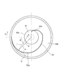
- FIG. 9 shows a top view of the sliding member 53.
- the sliding member 53 is formed in a spiral shape in which the length of the moving radius B extending from the rotation center is gradually shortened with respect to the central angle ⁇ from the maximum.
- the outer peripheral end (when the moving radius B is maximum) of the sliding member 53 is disposed on the outer peripheral edge of the receiving surface 50 b, and the inner peripheral end (when the moving radius B is minimum) is disposed inside the inner cylinder 52.
- the sliding member 53 connects two arcs 53a and 53b that are eccentric with respect to the rotation center, and the central angle ⁇ from the maximum of the radius B is formed to be 180 ° or more.
- the circular arc 53a is formed in a semicircular shape with a central angle ⁇ in the range of 0 ° to 180 °, and the circular arc 53b is formed in a range of the central angle ⁇ between 180 ° and 270 °.
- the radius of the receiving surface 50b is 50 mm
- the radius r of the arc 53a is 40 mm
- the eccentricity a of the arc 53a is 10 mm
- the radius r of the arc 53b is 20 mm
- the eccentricity a of the arc 53b is 10 mm.
- the dust on the floor surface is sucked from the suction port body 5 by driving the electric blower 6 and flows through the extension pipe 4 and the connection hose 3.
- the air flow including dust flows into the dust collecting container 22 of the dust collecting unit 20 through the connection port 10a and the inflow port 22a, and forms a swirling air flow in the dust collecting container 22.
- the relatively large dust contained in the airflow is removed by the centrifugal force of the swirling airflow, and is accumulated in the dust collecting container 22.
- the airflow from which large dust has been removed flows out from the outlet 51a into the inner cylinder 51 and rises, and fine dust is collected by the filter 37.
- the airflow that has passed through the filter 37 flows out of the dust collector 20 through the dust collector exhaust port 42a.
- the airflow flowing out from the dust collecting unit 20 flows through the duct 15 and is exhausted from the exhaust port 10b through the electric blower 6.
- the rotating body 31 When removing the filter 37, the rotating body 31 is rotated in the direction of arrow G (see FIG. 8) by the handle 34, and the dust drops from the filter 37 onto the receiving surface 50b.
- the dust on the receiving surface 50 b is guided to the inner peripheral side along the rotating sliding member 53 and is collected in the dust collecting container 22 through the inner cylinder 51.
- the angle ⁇ at an arbitrary point between the outer peripheral end and the inner peripheral end of the sliding member 53 is formed to be 60 ° to 90 °, dust on the receiving surface 50b is smoothly applied to the sliding member 53. You can guide along. If the angle ⁇ at an arbitrary point between the outer peripheral end and the inner peripheral end of the sliding member 53 is 45 ° or more, the sliding member 53 is sufficiently inclined with respect to the rotation direction, and the dust is smoothly slid. Guiding along the moving member 53 is possible.
- the receiving surface 50b disposed below the filter 37 is formed by a plane perpendicular to the axial direction, and the flexible sliding member 53 that rotates and slides on the receiving surface 50b causes dust to flow into the inner cylinder 51. Therefore, the dust collection unit 20 can be made smaller in the axial direction and the dust dropped from the filter 37 can be collected in the dust collection container 22. Therefore, the vacuum cleaner 1 can be reduced in size.
- a rotating body 31 having a handle 34 on the upper surface and holding a sliding member 53 on the lower side is rotatably supported by a shaft portion 31 b that passes through the filter 37.
- the dust removing member 33 and the filter 37 are rotated by the rotation of the rotating body 31. Therefore, it is possible to simultaneously remove dust from the filter 37 and collect dust in the dust collecting container 22 by operating the handle 34. Further, since the rotation direction of the handle 34 is restricted, the dust on the receiving surface 50b can be reliably collected in the dust collecting container 22.
- the dust removing member 33 may be fixed to the cover part 40 or the filter holding part 50, and the filter 37 and the sliding member 53 may rotate integrally with the rotating body 31.
- a rail portion 31e that extends in the radial direction from the shaft portion 31b and guides the handle 34 is provided, and the rail portion 31e is located forward of the handle 34 in the rotation direction with respect to the center line C perpendicular to the rotation axis of the rotating body 31. Since it curves toward the direction, the rotation direction of the handle 34 can be easily regulated.
- the angle ⁇ between the outer peripheral end diameter (dynamic diameter B) of the sliding member 53 and the tangent D is set to approximately 90 °, the dust disposed on the periphery of the receiving surface 50b can be smoothly removed. Can be guided inside.
- the sliding member 53 is formed on the receiving surface 50b by setting the angle ⁇ between the tangent line D and the diameter (dynamic radius B) of an arbitrary point between the outer peripheral end and the inner peripheral end to 45 ° to 90 °. Dust can be smoothly guided along the sliding member 53.
- the central angle between the outer peripheral end and the inner peripheral end of the sliding member 53 is formed to be 180 ° or more, the sliding member 53 is not bent suddenly. Thereby, the angle ⁇ of an arbitrary point of the sliding member 53 can be easily formed large and dust can be guided to the inner cylinder 51.
- the protruding portion 34b of the handle 34 may be formed so as to be tiltable with respect to the engaging portion 34a. Thereby, when the dust removal of the filter 37 is completed, the protrusion 34b can be tilted to reduce the height of the handle 34, and the dust collector 20 and the vacuum cleaner 1 can be further downsized.
- the vacuum cleaner 1 is formed in a canister type in which the suction port body 5 is connected to the main body portion 2 in which the electric blower 6 is housed via the connection hose 3, and the suction port body 5 is integrated with the main body portion 2. It may be a vertical vacuum cleaner provided.
- the present invention can be used in a vacuum cleaner equipped with a filter dust remover.
Landscapes
- Engineering & Computer Science (AREA)
- Mechanical Engineering (AREA)
- Filters For Electric Vacuum Cleaners (AREA)
- Filtering Of Dispersed Particles In Gases (AREA)
Abstract
一端面に開口面(22b)を有する断面円形の有底筒状に形成されるとともに周面に気流の流入口(22a)が設けられる集塵容器(22)と、開口面(22b)に配されるフィルタ(37)と、フィルタ(37)を叩打して除塵する除塵部材(33)と、フィルタ(37)の下方に配された軸方向に垂直な平面により形成されるとともに除塵部材(33)によりフィルタ(37)から脱落した塵埃を受ける受け面(50b)と、受け面(50b)に開口して下方に延びるとともに集塵容器(22)と同軸に配されて集塵容器(22)から流出する気流の流出口(51a)が周面に設けられる内筒(51)と、受け面(50b)上を回転摺動して塵埃を内筒(51)に導く渦巻状に形成された可撓性の摺動部材(53)とを備えた。
Description
本発明は、フィルタの除塵装置を備えた電気掃除機に関する。
従来の電気掃除機は特許文献1に開示されている。この電気掃除機は電動送風機を内装した本体部を備えている。本体部内には電動送風機の前方にサイクロン式の集塵部が配される。集塵部は上面に開口面を有する断面円形の有底筒状の集塵容器を備えている。集塵容器の周面には塵埃を含む気流を周接線方向に流入させる流入口が設けられる。集塵容器内には流入口から流入する空気によって旋回気流が形成される。
集塵容器の上面の開口面には集塵容器に対して着脱自在のフィルタ保持部により保持された平面視円形のフィルタが配される。フィルタ保持部はフィルタの下方を覆う円錐面から成る受け面を有し、受け面から下方に延びる内筒が一体に設けられる。内筒は集塵容器の中心軸上に配され、内筒の周面には集塵容器から気流が流出する流出口が開口する。
フィルタの上方には本体部の外装を形成するカバー部が設けられる。カバー部はフィルタ保持部に対して着脱自在に設けられ、上面に使用者が把持する把持部が設けられる。カバー部の内面にはフィルタと電動送風機との間を連通させる連通路が形成され、カバー部の背面に連通路の端面である集塵部排気口が開口する。
また、フィルタ保持部には除塵装置が設けられる。除塵装置はフィルタと一体に設けられた回転自在の回転体を備え、カバー部にはフィルタの上面よりも下方に突出する可撓性の除塵部材が設けられる。回転体は駆動モータによりフィルタと一体に回転し、除塵部材によりフィルタが叩打される。回転体の下部には受け面上を回転摺動する可撓性の摺動部材が設けられる。
上記構成の電気掃除機において、電動送風機の駆動によって吸込口体から被掃除面上の塵埃が空気とともに吸い込まれる。吸込口体から吸い込まれた空気は延長パイプ及び接続ホースを介して流入口から集塵部の集塵容器内に流入する。集塵容器に流入した空気は集塵容器内で旋回し、遠心力によって大きい塵埃が分離されて集塵容器内に堆積する。
大きい塵埃が除去された気流は流出口を介して内筒内を流通し、フィルタによって細かい塵埃が捕集される。細かい塵埃が除去された気流は連通路を流通し、集塵部排気口を介して集塵部から流出する。集塵部から流出した空気は電動送風機を通過して外部に排気される。これにより、被掃除面の掃除を行うことができる。
集塵部を本体部から脱着してカバー部と一体にフィルタ保持部を集塵容器から脱着すると、集塵容器に堆積した塵埃を廃棄することができる。
また、除塵装置の回転体を回転させると、除塵部材がフィルタを叩打してフィルタに捕集された塵埃が受け面上に脱落する。回転体の回転によって受け面には摺動部材が回転摺動し、円錐面から成る受け面上の塵埃が内筒に滑落する。これにより、フィルタの除塵が行われ、塵埃が内筒を介して集塵容器内に回収される。
しかしながら、上記従来の電気掃除機によると、フィルタの下方に配される受け面が塵埃を内筒に滑落させるために円錐面により形成される。このため、集塵部が軸方向に大きくなり、電気掃除機の大型化を招く問題があった。
本発明は、小型化を図ることのできる電気掃除機を提供することを目的とする。
上記目的を達成するために本発明は、一端面に開口面を有する断面円形の有底筒状に形成されるとともに周面に気流の流入口が設けられる集塵容器と、前記開口面に配されるフィルタと、前記フィルタを叩打して除塵する除塵部材と、前記フィルタの下方に配された軸方向に垂直な平面により形成されるとともに前記除塵部材により前記フィルタから脱落した塵埃を受ける受け面と、前記受け面に開口して下方に延びるとともに前記集塵容器と同軸に配されて前記集塵容器から流出する気流の流出口が周面に設けられる内筒と、前記受け面上を回転摺動して塵埃を前記内筒に導く渦巻状に形成された可撓性の摺動部材とを備えたことを特徴としている。
この構成によると、電動送風機の駆動によって流入口から塵埃を含む気流が集塵容器に流入し、内筒に設けた流出口を介して流出する。これにより、大きな塵埃が集塵容器内に堆積する。内筒を流通する気流は開口面に配されたフィルタにより細かい塵埃が捕集される。フィルタを通過した気流は電動送風機を通過して排気される。所定の操作によって除塵部材がフィルタを叩打するとフィルタが除塵され、フィルタに捕集された塵埃が平面から成る受け面上に脱落する。渦巻状の摺動部材は受け面上を回転摺動し、受け面に脱落した塵埃が内周側に配される内筒に導かれて集塵容器に回収される。
また本発明は、上記構成の電気掃除機において、前記フィルタを貫通する軸部によって回転自在に支持されるとともに下部に前記摺動部材が設けられる回転体と、前記回転体の上面に配されて前記回転体の回転操作を行うハンドルとを備え、前記回転体の回転によって前記除塵部材と前記フィルタとが衝突するとともに、前記受け面上の塵埃を前記摺動部材の内周側に導く方向に前記ハンドルの回転方向を規制したことを特徴としている。
この構成によると、ハンドルの操作によって回転体が回転して除塵部材がフィルタを叩打するとともに、摺動部材が受け面上を回転摺動する。受け面に摺動する摺動部材の内周側に塵埃を導く方向に回転体が回転するようにハンドルの回転方向が一方向に規制される。尚、フィルタが回転体と一体回転して除塵部材に衝突してもよく、除塵部材が回転体と一体回転してフィルタに衝突してもよい。
また本発明は、上記構成の電気掃除機において、前記軸部から径方向に延びて前記ハンドルを案内するレール部を備え、前記レール部が前記回転体の回転軸に垂直な中心線に対して外周側が前記ハンドルの回転方向前方に向かって湾曲することを特徴としている。
この構成によると、ハンドルはレール部の案内によって軸部から離れた位置に移動し、回転体を回転させる。この時、ハンドルは湾曲したレール部の曲率中心が配される側に周方向の荷重が加えられて回転体を回転させ、ハンドルの内周側への移動が抑制される。
また本発明は、上記構成の電気掃除機において、前記摺動部材の外周端の径と接線との角度を略90゜にしたことを特徴としている。
また本発明は、上記構成の電気掃除機において、前記摺動部材の外周端と内周端との間の任意の点の径と接線との角度を45゜~90゜にしたことを特徴としている。
また本発明は、上記構成の電気掃除機において、前記摺動部材の外周端と内周端との間の中心角を180゜以上に形成したことを特徴としている。
本発明によると、フィルタの下方に配した受け面を軸方向に垂直な平面により形成し、受け面上を回転摺動する可撓性の摺動部材が塵埃を内筒に導く渦巻状に形成されるので、集塵部を軸方向に小さくしてフィルタから脱落した塵埃を集塵容器に回収することができる。従って、電気掃除機の小型化を図ることができる。
以下に本発明の実施形態を図面を参照して説明する。図1は一実施形態の電気掃除機を示す斜視図である。電気掃除機1は電動送風機6(図2参照)を内装する本体部2を備えている。本体部2の背面には引き出し及び収納が可能な電源コード8が設けられる。電源コード8は電源プラグ9を先端に有し、商用電源のコンセントに差し込んで本体部2に電力供給される。
本体部2の前面には可撓性の接続ホース3が接続され、接続ホース3の先端には延長パイプ4が接続される。延長パイプ4の先端には床面に対峙する吸込口(不図示)を有した吸込口体5が設けられる。また、延長パイプ4にはパイプ把持部13及び操作部14が設けられる。使用者により操作部14を操作して掃除運転が実行され、パイプ把持部13を把持して吸込口体5を移動させる。
図2は本体部2の側面断面図を示している。本体部2は本体カバー10により覆われ、後部に電動送風機6が配される。本体カバー10の前面には接続ホース3(図1参照)を接続する接続口10aが開口し、背面には排気口10bが開口する。電動送風機6の前方には集塵室19(図3参照)が設けられ、集塵室19内にはサイクロン式の集塵部20が配される。詳細を後述するように集塵部20の集塵容器22は透明樹脂から成り、集塵容器22内を視認できる窓部10cが本体カバー10に設けられる。
集塵部20は接続口10aに連通する流入口22a及び塵埃を除去した気流が流出する集塵部排気口42aが設けられる。集塵部排気口42aと電動送風機6との間はダクト15により連結される。
集塵部20の上部には本体カバー10に連続して本体部2の外装を形成するカバー部40が配される。カバー部40の上面には後部で枢支される回動自在の把持部41が設けられ、カバー部40の上部後方には本体カバー10に係合する係合部43が設けられる。係合部43は把持部41の回動によって前後に進退する。
本体カバー10にカバー部40の前部を掛けて後方の係合部43を係合させることによって集塵部20が本体部2に装着される。把持部41の先端を引き上げると係合部43が前進して本体カバー10との係合を解除され、図3に示すように集塵部20を本体部2から上方に脱着することができる。これにより、集塵部20で集塵した塵埃を廃棄することができる。
図4、図5は集塵部20の斜視図及び側面断面図を示している。集塵部20はカバー部40、フィルタ保持部50及び集塵容器22を有している。集塵容器22は透明樹脂から成り、上面に開口面22bを有した断面略円形の有底筒状に形成される。集塵容器22の前部の周面には接続口10a(図2参照)に連通して接続ホース3(図1参照)からの気流が流入する流入口22aが設けられる。
集塵容器22には流入口22aを介して周接線方向に気流が流入し、集塵容器22内に旋回気流が形成される。これにより、サイクロン式の集塵装置が形成され、気流に含まれる塵埃を遠心力により分離する。また、集塵容器22の後部の周面には水平軸で回動自在のクリップ23が設けられる。
フィルタ保持部50は平面視円形のフィルタ37を保持する。フィルタ37はプリーツフィルタから成り、軸方向に垂直な方向に山部と谷部とが連続するように折り曲げて形成される。これにより、フィルタ37は広い捕集面積を有し、集塵容器22の開口面22bを覆って塵埃を捕集する。
フィルタ保持部50は平面視円形のフィルタ37の周面に沿う環状部50aを有し、集塵容器22に対して着脱自在に設けられる。集塵容器22にフィルタ保持部50の前部を掛けてクリップ23をフィルタ保持部50の背面に係合させると、フィルタ保持部50が集塵容器22に装着される。クリップ23を回動してフィルタ保持部50との係合を解除すると、集塵容器22からフィルタ保持部50を脱着することができる。
フィルタ保持部50にはフィルタ37の下方に配された受け面50bが設けられる。受け面50bは軸方向に垂直な平面により形成され、中央に開口する開口部50c(図9参照)の周縁から下方に延びる内筒51が設けられる。内筒51は集塵容器22と同軸に配され、周面に集塵容器22から流出する気流の流出口51aが設けられる。また、フィルタ保持部50には後述するように、フィルタ37により捕集した塵埃を除塵する除塵装置30(図6参照)が設けられる。
カバー部40の上面は前方が下がる傾斜面に形成され、カバー部40の内部にはフィルタ37とダクト15(図2参照)とを連通させる連通路42が形成される。カバー部40の背面には連通路42の端面である集塵部排気口42aが開口する。カバー部40は背面に設けたヒンジ部60によってフィルタ保持部50に枢支され、フィルタ37の上方を開閉する。
図6は集塵部20のカバー部40を開いた状態を示す斜視図である。カバー部40の前部の下面にはフック46及び押圧部材45が設けられる。フック46はカバー部40と一体に設けられ、周方向に弾性変形可能に形成される。押圧部材45はカバー部40の下面から突出して上下移動可能に設けられ、下方に付勢される。
フィルタ保持部50の環状部50aにはヒンジ部60に対して径方向に対向した前部に当接部54及びロック部材52が設けられる。当接部54は押圧部材45が当接し、押圧部材45の付勢力によって押圧される。ロック部材52は周方向に可動に設けられ、圧縮バネ(不図示)によって一方向(矢印E1方向)に付勢される。ロック部材52はフック46が係合してカバー部40とフィルタ保持部50との閉止状態をロックする。
ロック部材52を付勢力に抗して他方向(矢印E2方向)に移動させると、ロック部材52とフック46との係合が解除される。これにより、カバー部40とフィルタ保持部50との閉止状態が解除される。この時、押圧部材45は圧縮バネ(不図示)の付勢力によって当接部54を押圧し、カバー部40の前部がポップアップして所定量持ち上げられる。これにより、把持部41(図3参照)やカバー部40の前部を把持してカバー部40を容易に開くことができる。
フィルタ保持部50にはフィルタ37を除塵する除塵装置30が設けられる。除塵装置30は平面視円形の樹脂成形品から成る回転体31を備えている。回転体31は下方に延びるシャフト31d(図5参照)を有した軸部31bが中心部に設けられる。シャフト31dがフィルタ37を貫通する嵌合孔37a(図5参照)に嵌合し、軸部31bを介して回転体31がフィルタ37に対して回転自在に支持される。
回転体31にはフィルタ37の周縁の上方に配される円形の環状部31cが設けられる。環状部31cは軸部31bから放射状に延びる複数の腕部31aにより支持され、各腕部31a間は開口して気流が流通する。
また、回転体31の軸部31bと環状部31cとの間には回転軸に垂直な中心線C(図7参照)に対して湾曲したレール部31eが形成される。レール部31eにはハンドル34の下部に設けた係合部34aが係合し、ハンドル34がレール部31eに対して回転自在に保持される。ハンドル34は係合部34aから上方に突出して使用者の手指により摘持される突出部34bが設けられる。突出部34bを摘持してハンドル34がレール部31eの案内によって回転体31の径方向に移動可能になっている。
図7は回転体31の上面図を示している。同図に示すように、ハンドル34を軸部31bに重なる位置に配置すると、各腕部31a間の開口部からハンドル34が退避する。これにより、フィルタ37を通過する気流のハンドル34による遮蔽が回避される。従って、電気掃除機1の吸引力の低下を防止することができる。
また、図8に示すように、ハンドル34を回転体31の周部に移動して軸部31bから離れた位置に配置すると、突出部34bを摘持して回転体31を回転させることができる。この時、ハンドル34は湾曲したレール部31eの曲率中心が配される側に周方向の荷重Fが加えられ、回転体31を図中、時計回り(矢印G方向)に回転させる。これにより、荷重Fの分力がレール部31eの外周側に向くため、ハンドル34の内周側への移動を抑制して回転体31を容易に回転させることができる。
回転体31を図中、反時計回りに回転させると、ハンドル34の荷重の分力がレール部31eの内周側に向く。これにより、ハンドル34が内周側に移動して回転体31を容易に回転させることができない。従って、湾曲したレール部31eによって回転体31の図中、反時計回りの回転を規制する回転規制部が構成される。この時、レール部31eは外周側がハンドル34の回転方向前方に向かって湾曲する。尚、回転体31を図中、反時計回りに回転できないようにするストッパを設けてもよい。
前述の図5において、シャフト31dの下部にはフィルタ37の下方に配される支持部材31fが一体に設けられる。支持部材31fの上面にはフィルタ37の山部間に延びる可撓性の除塵部材33が取り付けられる。また、支持部材31fの下面にはゴムや軟質樹脂等から成る可撓性の摺動部材53が設けられる。摺動部材53は回転体31と一体に回転して受け面50b上を回転摺動する。
カバー部40を開くとハンドル34が露出し、ハンドル34の突出部34bを摘持して回転体31を回転させるとフィルタ37が除塵部材33により叩打される。これにより、フィルタ37に捕集された塵埃が受け面50b上に脱落し、フィルタ37の除塵を行うことができる。
尚、除塵部材33をフィルタ37の上方に配置してもよい。この時、回転体31の軸部31bに嵌合孔を形成し、嵌合孔に嵌合するシャフトをフィルタ37に設けてもよい。
図9は摺動部材53の上面図を示している。摺動部材53は回転中心から延びる動径Bの長さが最大時からの中心角θに対して徐々に短縮された渦巻状に形成される。摺動部材53の外周端(動径Bの最大時)は受け面50bの外周縁に配され、内周端(動径Bの最小時)は内筒52の内側に配される。
本実施形態では摺動部材53は回転中心に対して偏心した2つの円弧53a、53bを連結し、動径Bの最大時からの中心角θが180゜以上に形成される。円弧53aは中心角θが0゜~180゜の範囲に半円状に形成され、円弧53bは中心角θが180゜~270゜の範囲に形成される。
円弧53a、53bの半径をr、偏心量をaとし、摺動部材53上の任意の点の径と接線との角度(動径Bと接線Dとの角度)をαとすると、式(1)の関係がある。これにより、角度αは式(2)で表わされる。
a・|sinθ|=r・cosα ・・・(1)
α=arccos(a/r・|sinθ|) ・・・(2)
α=arccos(a/r・|sinθ|) ・・・(2)
本実施形態は受け面50bの半径を50mm、円弧53aの半径r=40mm、円弧53aの偏心量a=10mm、円弧53bの半径r=20mm、円弧53bの偏心量a=10mmに形成している。この時、円弧53aにおける角度αの最大値は90゜(θ=0゜)であり、最小値は75.5゜(θ=90゜)である。また、円弧53bにおける角度αの最大値は90゜(θ=180゜)であり、最小値は60゜(θ=270゜)である。即ち、摺動部材53の外周端と内周端との間の任意の点の角度αは60゜~90゜に形成される。
上記構成の電気掃除機1において、電動送風機6の駆動によって吸込口体5から床面の塵埃が吸い込まれ、延長パイプ4及び接続ホース3を流通する。塵埃を含む気流は接続口10a及び流入口22aを介して集塵部20の集塵容器22に流入し、集塵容器22内に旋回気流を形成する。旋回気流の遠心力によって気流に含まれる比較的大きな塵埃が除去され、集塵容器22内に堆積する。
大きな塵埃が除去された気流は流出口51aから内筒51内に流出して上昇し、フィルタ37により細かい塵埃が捕集される。フィルタ37を通過した気流は集塵部排気口42aを介して集塵部20から流出する。集塵部20から流出した気流はダクト15を流通し、電動送風機6を介して排気口10bから排気される。
把持部41を引き上げると係合部43と本体カバー10との係合が解除され、集塵部20が集塵室19から脱着される。クリップ23の回動によってフィルタ保持部50がカバー部40と一体に集塵容器22から脱着されると、集塵容器22内の塵埃が廃棄される。ロック部材52の操作によってカバー部40を開くとフィルタ37及びハンドル34が露出する。これにより、フィルタ37の水洗い等の清掃やフィルタ37の除塵を行うことができる。
フィルタ37の除塵時にはハンドル34によって回転体31が矢印G方向(図8参照)に回転し、フィルタ37から受け面50b上に塵埃が脱落する。受け面50b上の塵埃は回転する摺動部材53に沿って内周側に案内され、内筒51を介して集塵容器22に回収される。
本実施形態では前述した形状の摺動部材53によって受け面50b上に塵埃を残存させずに集塵容器22に回収されることが確認された。この時、摺動部材53の外周端の角度αを90゜に形成しているので、受け面50bの周縁に配された塵埃を円滑に摺動部材53の内側に案内することができる。摺動部材53の外周端の角度αは略90゜であれば同様の効果が得られる。
また、摺動部材53の外周端と内周端との間の任意の点の角度αを60゜~90゜に形成しているので、受け面50b上の塵埃を円滑に摺動部材53に沿って案内することができる。尚、摺動部材53の外周端と内周端との間の任意の点の角度αが45゜以上であれば回転方向に対して摺動部材53の傾斜が十分大きく、塵埃を円滑に摺動部材53に沿って案内することができる。
本実施形態によると、フィルタ37の下方に配した受け面50bを軸方向に垂直な平面により形成し、受け面50b上を回転摺動する可撓性の摺動部材53が塵埃を内筒51に導く渦巻状に形成されるので、集塵部20を軸方向に小さくしてフィルタ37から脱落した塵埃を集塵容器22に回収することができる。従って、電気掃除機1の小型化を図ることができる。
また、上面にハンドル34を有して下部に摺動部材53を保持する回転体31がフィルタ37を貫通する軸部31bによって回転自在に支持され、回転体31の回転によって除塵部材33とフィルタ37とが衝突するので、ハンドル34の操作によりフィルタ37の除塵と塵埃の集塵容器22への回収を同時に行うことができる。また、ハンドル34の回転方向が規制されるので受け面50b上の塵埃を確実に集塵容器22に回収することができる。尚、除塵部材33をカバー部40またはフィルタ保持部50に固定し、フィルタ37及び摺動部材53が回転体31と一体に回転してもよい。
また、軸部31bから径方向に延びてハンドル34を案内するレール部31eを備え、レール部31eが回転体31の回転軸に垂直な中心線Cに対して外周側がハンドル34の回転方向前方に向かって湾曲するので、ハンドル34の回転方向を容易に規制することができる。
また、摺動部材53の外周端の径(動径B)と接線Dとの角度αを略90゜にすることにより、受け面50bの周縁に配された塵埃を円滑に摺動部材53の内側に案内することができる。
また、摺動部材53は外周端と内周端との間の任意の点の径(動径B)と接線Dとの角度αを45゜~90゜にすることにより、受け面50b上の塵埃を円滑に摺動部材53に沿って案内することができる。
尚、式(3)に示すように、摺動部材53を動径Bの長さ(R)を中心角θに対して線型に形成すると、角度αが常に90゜になるのでより望ましい。
R=k+jθ (k、jは定数) ・・・(3)
また、摺動部材53の外周端と内周端との間の中心角を180゜以上に形成したので、摺動部材53が急激に曲げられない。これにより、摺動部材53の任意の点の角度αを容易に大きく形成して内筒51まで塵埃を導くことができる。
本実施形態において、ハンドル34を回転体31の軸部31bの方向に付勢する付勢手段を設けるとより望ましい。これにより、フィルタ37の除塵が完了してハンドル34から手指を離すと、ハンドル34が付勢手段の付勢によって軸部31bに重なる位置に配される。従って、ハンドル34による気流の遮蔽をより確実に防止することができる。
また、ハンドル34の突出部34bを係合部34aに対して傾倒自在に形成してもよい。これにより、フィルタ37の除塵が完了すると突出部34bを傾倒してハンドル34の高さを低くすることができ、集塵部20及び電気掃除機1のより小型化を図ることができる。
また、電気掃除機1が電動送風機6を内装する本体部2に吸込口体5が接続ホース3を介して接続されるキャニスター型に形成されるが、本体部2に吸込口体5を一体に設けた縦型の電気掃除機であってもよい。
本発明によると、フィルタの除塵装置を備えた電気掃除機に利用することができる。
1 電気掃除機
2 本体部
3 接続ホース
4 延長パイプ
5 吸込口体
6 電動送風機
10 本体カバー
13 パイプ把持部
14 操作部
15 ダクト
19 集塵室
20 集塵部
22 集塵容器
22a 流入口
22b 開口面
23 クリップ
30 除塵装置
31 回転体
31b 軸部
31d シャフト
31e レール部
33 除塵部材
34 ハンドル
34a 係合部
34b 突出部
37 フィルタ
37a 嵌合孔
40 カバー部
41 把持部
42 連通路
42a 集塵部排気口
43 係合部
45 押圧部材
46 フック
50 フィルタ保持部
50b 受け面
51 内筒
51a 流出口
52 ロック部材
53 摺動部材
54 当接部
60 ヒンジ部
2 本体部
3 接続ホース
4 延長パイプ
5 吸込口体
6 電動送風機
10 本体カバー
13 パイプ把持部
14 操作部
15 ダクト
19 集塵室
20 集塵部
22 集塵容器
22a 流入口
22b 開口面
23 クリップ
30 除塵装置
31 回転体
31b 軸部
31d シャフト
31e レール部
33 除塵部材
34 ハンドル
34a 係合部
34b 突出部
37 フィルタ
37a 嵌合孔
40 カバー部
41 把持部
42 連通路
42a 集塵部排気口
43 係合部
45 押圧部材
46 フック
50 フィルタ保持部
50b 受け面
51 内筒
51a 流出口
52 ロック部材
53 摺動部材
54 当接部
60 ヒンジ部
Claims (6)
- 一端面に開口面を有する断面円形の有底筒状に形成されるとともに周面に気流の流入口が設けられる集塵容器と、前記開口面に配されるフィルタと、前記フィルタを叩打して除塵する除塵部材と、前記フィルタの下方に配された軸方向に垂直な平面により形成されるとともに前記除塵部材により前記フィルタから脱落した塵埃を受ける受け面と、前記受け面に開口して下方に延びるとともに前記集塵容器と同軸に配されて前記集塵容器から流出する気流の流出口が周面に設けられる内筒と、前記受け面上を回転摺動して塵埃を前記内筒に導く渦巻状に形成された可撓性の摺動部材とを備えたことを特徴とする電気掃除機。
- 前記フィルタを貫通する軸部によって回転自在に支持されるとともに下部に前記摺動部材が設けられる回転体と、前記回転体の上面に配されて前記回転体の回転操作を行うハンドルとを備え、前記回転体の回転によって前記除塵部材と前記フィルタとが衝突するとともに、前記受け面上の塵埃を前記摺動部材の内周側に導く方向に前記ハンドルの回転方向を規制したことを特徴とする請求項1に記載の電気掃除機。
- 前記軸部から径方向に延びて前記ハンドルを案内するレール部を備え、前記レール部が前記回転体の回転軸に垂直な中心線に対して外周側が前記ハンドルの回転方向前方に向かって湾曲することを特徴とする請求項2に記載の電気掃除機。
- 前記摺動部材の外周端の径と接線との角度を略90゜にしたことを特徴とする請求項1~請求項3のいずれかに記載の電気掃除機。
- 前記摺動部材の外周端と内周端との間の任意の点の径と接線との角度を45゜~90゜にしたことを特徴とする請求項1~請求項3のいずれかに記載の電気掃除機。
- 前記摺動部材の外周端と内周端との間の中心角を180゜以上に形成したことを特徴とする請求項1~請求項3のいずれかに記載の電気掃除機。
Priority Applications (1)
| Application Number | Priority Date | Filing Date | Title |
|---|---|---|---|
| CN201180041711.8A CN103079443B (zh) | 2010-09-01 | 2011-07-28 | 电动吸尘器 |
Applications Claiming Priority (2)
| Application Number | Priority Date | Filing Date | Title |
|---|---|---|---|
| JP2010195403A JP4866477B1 (ja) | 2010-09-01 | 2010-09-01 | 電気掃除機 |
| JP2010-195403 | 2010-09-01 |
Publications (1)
| Publication Number | Publication Date |
|---|---|
| WO2012029469A1 true WO2012029469A1 (ja) | 2012-03-08 |
Family
ID=45772578
Family Applications (1)
| Application Number | Title | Priority Date | Filing Date |
|---|---|---|---|
| PCT/JP2011/067297 Ceased WO2012029469A1 (ja) | 2010-09-01 | 2011-07-28 | 電気掃除機 |
Country Status (3)
| Country | Link |
|---|---|
| JP (1) | JP4866477B1 (ja) |
| CN (1) | CN103079443B (ja) |
| WO (1) | WO2012029469A1 (ja) |
Cited By (1)
| Publication number | Priority date | Publication date | Assignee | Title |
|---|---|---|---|---|
| WO2017010466A1 (ja) * | 2015-07-13 | 2017-01-19 | 東芝ライフスタイル株式会社 | 塵埃分離装置および電気掃除機 |
Families Citing this family (5)
| Publication number | Priority date | Publication date | Assignee | Title |
|---|---|---|---|---|
| US10327613B2 (en) | 2015-05-19 | 2019-06-25 | Jiangsu Media Cleaning Appliances Co., Ltd. | Filteration assembly for vacuum cleaner and vacuum cleaner having same |
| JP7011530B2 (ja) * | 2018-05-14 | 2022-01-26 | 東芝ライフスタイル株式会社 | 電気掃除機 |
| JP7058173B2 (ja) * | 2018-05-14 | 2022-04-21 | 東芝ライフスタイル株式会社 | 電気掃除機 |
| JP7084776B2 (ja) * | 2018-05-14 | 2022-06-15 | 東芝ライフスタイル株式会社 | 電気掃除機 |
| JP7116641B2 (ja) * | 2018-09-07 | 2022-08-10 | 東芝ライフスタイル株式会社 | 電気掃除機 |
Citations (2)
| Publication number | Priority date | Publication date | Assignee | Title |
|---|---|---|---|---|
| JPS55179655U (ja) * | 1979-06-09 | 1980-12-24 | ||
| JP2009112506A (ja) * | 2007-11-06 | 2009-05-28 | Sharp Corp | 電気掃除機 |
Family Cites Families (4)
| Publication number | Priority date | Publication date | Assignee | Title |
|---|---|---|---|---|
| JPS4842758Y1 (ja) * | 1970-07-16 | 1973-12-11 | ||
| US7785381B2 (en) * | 2007-04-30 | 2010-08-31 | Samsung Gwangju Electronics Co., Ltd. | Dust collecting apparatus with combined compacting and filter cleaning for a vacuum cleaner |
| JP4798637B2 (ja) * | 2008-10-20 | 2011-10-19 | シャープ株式会社 | 集塵装置および電気掃除機 |
| JP4865881B2 (ja) * | 2010-04-16 | 2012-02-01 | シャープ株式会社 | 電気掃除機 |
-
2010
- 2010-09-01 JP JP2010195403A patent/JP4866477B1/ja not_active Expired - Fee Related
-
2011
- 2011-07-28 CN CN201180041711.8A patent/CN103079443B/zh not_active Expired - Fee Related
- 2011-07-28 WO PCT/JP2011/067297 patent/WO2012029469A1/ja not_active Ceased
Patent Citations (2)
| Publication number | Priority date | Publication date | Assignee | Title |
|---|---|---|---|---|
| JPS55179655U (ja) * | 1979-06-09 | 1980-12-24 | ||
| JP2009112506A (ja) * | 2007-11-06 | 2009-05-28 | Sharp Corp | 電気掃除機 |
Cited By (2)
| Publication number | Priority date | Publication date | Assignee | Title |
|---|---|---|---|---|
| WO2017010466A1 (ja) * | 2015-07-13 | 2017-01-19 | 東芝ライフスタイル株式会社 | 塵埃分離装置および電気掃除機 |
| JP2017018407A (ja) * | 2015-07-13 | 2017-01-26 | 東芝ライフスタイル株式会社 | 塵埃分離装置および電気掃除機 |
Also Published As
| Publication number | Publication date |
|---|---|
| CN103079443A (zh) | 2013-05-01 |
| JP4866477B1 (ja) | 2012-02-01 |
| JP2012050665A (ja) | 2012-03-15 |
| CN103079443B (zh) | 2017-06-13 |
Similar Documents
| Publication | Publication Date | Title |
|---|---|---|
| US7581286B2 (en) | Vacuum cleaner and dust collection unit thereof | |
| RU2422077C2 (ru) | Портативный чистящий прибор | |
| JP5677796B2 (ja) | 電気掃除機 | |
| JP4866477B1 (ja) | 電気掃除機 | |
| EP1629758B1 (en) | Dust collection unit for vacuum cleaner | |
| KR100560332B1 (ko) | 집진통 고정/분리 장치 및 이를 구비하는 사이클론집진장치 | |
| JP5070322B2 (ja) | 電気掃除機 | |
| JP3813882B2 (ja) | 電気掃除機 | |
| JP5703408B1 (ja) | 電気掃除機 | |
| CN110944556A (zh) | 灰尘分离装置 | |
| JP2011078463A (ja) | 電気掃除機 | |
| JP6047753B2 (ja) | 電気掃除機 | |
| JP5726690B2 (ja) | 電気掃除機 | |
| JP2012050669A (ja) | 電気掃除機 | |
| CN107303164B (zh) | 电吸尘器 | |
| JP5406655B2 (ja) | 電気掃除機 | |
| JP5996030B2 (ja) | 電気掃除機 | |
| JP6382247B2 (ja) | 電気掃除機 | |
| JP2015204929A (ja) | 電気掃除機 | |
| JP6660431B2 (ja) | 電気掃除機 | |
| JP5945724B2 (ja) | 電気掃除機 | |
| CN111938500A (zh) | 电动吸尘器及其集尘装置 | |
| JP5903543B2 (ja) | 電気掃除機 | |
| JP2015024275A (ja) | 電気掃除機 | |
| JP6302730B2 (ja) | 電気掃除機 |
Legal Events
| Date | Code | Title | Description |
|---|---|---|---|
| WWE | Wipo information: entry into national phase |
Ref document number: 201180041711.8 Country of ref document: CN |
|
| 121 | Ep: the epo has been informed by wipo that ep was designated in this application |
Ref document number: 11821487 Country of ref document: EP Kind code of ref document: A1 |
|
| NENP | Non-entry into the national phase |
Ref country code: DE |
|
| 122 | Ep: pct application non-entry in european phase |
Ref document number: 11821487 Country of ref document: EP Kind code of ref document: A1 |