WO2012023591A1 - 画像形成装置 - Google Patents
画像形成装置 Download PDFInfo
- Publication number
- WO2012023591A1 WO2012023591A1 PCT/JP2011/068720 JP2011068720W WO2012023591A1 WO 2012023591 A1 WO2012023591 A1 WO 2012023591A1 JP 2011068720 W JP2011068720 W JP 2011068720W WO 2012023591 A1 WO2012023591 A1 WO 2012023591A1
- Authority
- WO
- WIPO (PCT)
- Prior art keywords
- cartridge
- door
- image forming
- forming apparatus
- contact portion
- Prior art date
- Legal status (The legal status is an assumption and is not a legal conclusion. Google has not performed a legal analysis and makes no representation as to the accuracy of the status listed.)
- Ceased
Links
Images


Classifications
-
- G—PHYSICS
- G03—PHOTOGRAPHY; CINEMATOGRAPHY; ANALOGOUS TECHNIQUES USING WAVES OTHER THAN OPTICAL WAVES; ELECTROGRAPHY; HOLOGRAPHY
- G03G—ELECTROGRAPHY; ELECTROPHOTOGRAPHY; MAGNETOGRAPHY
- G03G21/00—Arrangements not provided for by groups G03G13/00 - G03G19/00, e.g. cleaning, elimination of residual charge
- G03G21/16—Mechanical means for facilitating the maintenance of the apparatus, e.g. modular arrangements
- G03G21/1661—Mechanical means for facilitating the maintenance of the apparatus, e.g. modular arrangements means for handling parts of the apparatus in the apparatus
- G03G21/1671—Mechanical means for facilitating the maintenance of the apparatus, e.g. modular arrangements means for handling parts of the apparatus in the apparatus for the photosensitive element
-
- G—PHYSICS
- G03—PHOTOGRAPHY; CINEMATOGRAPHY; ANALOGOUS TECHNIQUES USING WAVES OTHER THAN OPTICAL WAVES; ELECTROGRAPHY; HOLOGRAPHY
- G03G—ELECTROGRAPHY; ELECTROPHOTOGRAPHY; MAGNETOGRAPHY
- G03G21/00—Arrangements not provided for by groups G03G13/00 - G03G19/00, e.g. cleaning, elimination of residual charge
- G03G21/16—Mechanical means for facilitating the maintenance of the apparatus, e.g. modular arrangements
- G03G21/1604—Arrangement or disposition of the entire apparatus
-
- G—PHYSICS
- G03—PHOTOGRAPHY; CINEMATOGRAPHY; ANALOGOUS TECHNIQUES USING WAVES OTHER THAN OPTICAL WAVES; ELECTROGRAPHY; HOLOGRAPHY
- G03G—ELECTROGRAPHY; ELECTROPHOTOGRAPHY; MAGNETOGRAPHY
- G03G15/00—Apparatus for electrographic processes using a charge pattern
- G03G15/06—Apparatus for electrographic processes using a charge pattern for developing
- G03G15/08—Apparatus for electrographic processes using a charge pattern for developing using a solid developer, e.g. powder developer
- G03G15/0822—Arrangements for preparing, mixing, supplying or dispensing developer
- G03G15/0863—Arrangements for preparing, mixing, supplying or dispensing developer provided with identifying means or means for storing process- or use parameters, e.g. an electronic memory
-
- G—PHYSICS
- G03—PHOTOGRAPHY; CINEMATOGRAPHY; ANALOGOUS TECHNIQUES USING WAVES OTHER THAN OPTICAL WAVES; ELECTROGRAPHY; HOLOGRAPHY
- G03G—ELECTROGRAPHY; ELECTROPHOTOGRAPHY; MAGNETOGRAPHY
- G03G21/00—Arrangements not provided for by groups G03G13/00 - G03G19/00, e.g. cleaning, elimination of residual charge
- G03G21/16—Mechanical means for facilitating the maintenance of the apparatus, e.g. modular arrangements
- G03G21/1604—Arrangement or disposition of the entire apparatus
- G03G21/1623—Means to access the interior of the apparatus
- G03G21/1633—Means to access the interior of the apparatus using doors or covers
-
- G—PHYSICS
- G03—PHOTOGRAPHY; CINEMATOGRAPHY; ANALOGOUS TECHNIQUES USING WAVES OTHER THAN OPTICAL WAVES; ELECTROGRAPHY; HOLOGRAPHY
- G03G—ELECTROGRAPHY; ELECTROPHOTOGRAPHY; MAGNETOGRAPHY
- G03G21/00—Arrangements not provided for by groups G03G13/00 - G03G19/00, e.g. cleaning, elimination of residual charge
- G03G21/16—Mechanical means for facilitating the maintenance of the apparatus, e.g. modular arrangements
- G03G21/1661—Mechanical means for facilitating the maintenance of the apparatus, e.g. modular arrangements means for handling parts of the apparatus in the apparatus
- G03G21/1676—Mechanical means for facilitating the maintenance of the apparatus, e.g. modular arrangements means for handling parts of the apparatus in the apparatus for the developer unit
-
- G—PHYSICS
- G03—PHOTOGRAPHY; CINEMATOGRAPHY; ANALOGOUS TECHNIQUES USING WAVES OTHER THAN OPTICAL WAVES; ELECTROGRAPHY; HOLOGRAPHY
- G03G—ELECTROGRAPHY; ELECTROPHOTOGRAPHY; MAGNETOGRAPHY
- G03G2215/00—Apparatus for electrophotographic processes
- G03G2215/06—Developing structures, details
- G03G2215/066—Toner cartridge or other attachable and detachable container for supplying developer material to replace the used material
- G03G2215/0695—Toner cartridge or other attachable and detachable container for supplying developer material to replace the used material using identification means or means for storing process or use parameters
- G03G2215/0697—Toner cartridge or other attachable and detachable container for supplying developer material to replace the used material using identification means or means for storing process or use parameters being an electronically readable memory
-
- G—PHYSICS
- G03—PHOTOGRAPHY; CINEMATOGRAPHY; ANALOGOUS TECHNIQUES USING WAVES OTHER THAN OPTICAL WAVES; ELECTROGRAPHY; HOLOGRAPHY
- G03G—ELECTROGRAPHY; ELECTROPHOTOGRAPHY; MAGNETOGRAPHY
- G03G2221/00—Processes not provided for by group G03G2215/00, e.g. cleaning or residual charge elimination
- G03G2221/16—Mechanical means for facilitating the maintenance of the apparatus, e.g. modular arrangements and complete machine concepts
- G03G2221/1651—Mechanical means for facilitating the maintenance of the apparatus, e.g. modular arrangements and complete machine concepts for connecting the different parts
- G03G2221/1654—Locks and means for positioning or alignment
-
- G—PHYSICS
- G03—PHOTOGRAPHY; CINEMATOGRAPHY; ANALOGOUS TECHNIQUES USING WAVES OTHER THAN OPTICAL WAVES; ELECTROGRAPHY; HOLOGRAPHY
- G03G—ELECTROGRAPHY; ELECTROPHOTOGRAPHY; MAGNETOGRAPHY
- G03G2221/00—Processes not provided for by group G03G2215/00, e.g. cleaning or residual charge elimination
- G03G2221/16—Mechanical means for facilitating the maintenance of the apparatus, e.g. modular arrangements and complete machine concepts
- G03G2221/1678—Frame structures
- G03G2221/169—Structural door designs
Definitions
- the present invention relates to an image forming apparatus such as a copying machine and a facsimile.
- an image forming apparatus main body a door that can be opened and closed with respect to it, and a first cartridge that can be attached to and detached from the image forming apparatus main body when the door is opened;
- An image forming apparatus having a second cartridge removable above the cartridge, the door including a contact portion contacting the second cartridge in a state where the door is closed;
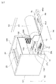
- FIG. 1A is a perspective view of the image forming apparatus according to the first embodiment.
- FIG. 1B is a block diagram of the image forming apparatus according to the first embodiment.
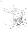
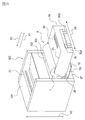
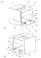
- FIG. 2 is a perspective view of the image forming apparatus according to the first embodiment with the door opened.
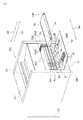
- FIG. 3 is a view for explaining attachment and detachment of the developing cartridge according to the first embodiment.
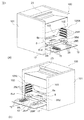
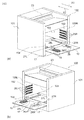
- FIG. 4 is a perspective view of the image forming apparatus in a state in which the developing cartridge according to the first embodiment is removed.
- FIG. 5 is a perspective view of the image forming apparatus from which the cartridge according to the first embodiment is removed.
- FIG. 6 is a perspective view of the developing cartridge according to the first embodiment.
- FIG. 7 is a view for explaining attachment and detachment of the drum cartridge according to the first embodiment.
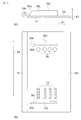
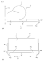
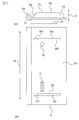
- FIG. 8A is a left side view of the door according to the first embodiment.
- FIG. 8B is a top view of the door according to the first embodiment.
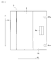
- FIG. 9 is a left side view of a door having an attachment / detachment path restricting member of another shape.
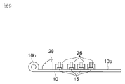
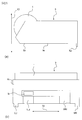
- FIG. 10 is a perspective view of the drum cartridge according to the first embodiment.
- FIG. 11 is a top view of the relief portion of the drum cartridge according to the first embodiment.
- FIG. 12A is a left side view of the door according to the second embodiment.
- FIG. 12 (b) is a top view of the door according to the second embodiment.
- FIG. 13 is a top view of the drum cartridge according to the second embodiment.
- FIG. 14A is a perspective view of the developing cartridge according to the second embodiment.
- FIG. 14B is a top view of the developing cartridge according to the second embodiment.
- FIG. 15A is a left side view of the drum cartridge according to the third embodiment.
- FIG. 15B is a front view of the drum cartridge according to the third embodiment.
- FIG. 16A is a left side view of the door according to the third embodiment.
- FIG. 16B is a top view of the door according to the third embodiment.
- FIGS. 17A and 17B are left side views showing one form of the drum cartridge according to the third embodiment.
- FIG. 18A is a perspective view of the image forming apparatus according to the fourth embodiment.
- FIG. 18B is a block diagram of an image forming apparatus according to the fourth embodiment.
- FIG. 19 is a perspective view of the image forming apparatus according to the fourth embodiment with the door opened.
- FIG. 20 is a view for explaining attachment and detachment of the all-in-one cartridge according to the fourth embodiment.
- FIG. 21 is a perspective view of the image forming apparatus with the all-in-one cartridge according to the fourth embodiment removed.
- FIG. 22A is a left side view of the door according to the fourth embodiment.
- FIG. 22B is a top view of the door according to the fourth embodiment.
- FIG. 23 is a perspective view of the all-in-one cartridge according to the fourth embodiment.
- FIG. 24A is a left side view of the door according to the fifth embodiment.
- FIG. 24 (b) is a top view of the door according to the fifth embodiment.
- FIG. 25 is a top view of the all-in-one cartridge according to the fifth embodiment.
- FIG. 26A is a left side view of the all-in-one cartridge according to the sixth embodiment.
- FIG. 26B is a front view of the all-in-one cartridge according to the sixth embodiment.
- FIG. 1A is a perspective view of an image forming apparatus according to the present embodiment.
- FIG. 1B is a block diagram of an image forming apparatus according to the present embodiment.
- the image forming apparatus 100 of the present embodiment has developing cartridges (second cartridges) 4 y, 4 m, 4 c, 4 k and a drum cartridge (first cartridge) 8.
- the developing cartridges 4y to 4k are removably mounted on the developing cartridge mounting portion 102 of the image forming apparatus main body 101 with the door 10 opened.
- FIG. 1 is a perspective view of an image forming apparatus according to the present embodiment.
- FIG. 1B is a block diagram of an image forming apparatus according to the present embodiment.
- the image forming apparatus 100 of the present embodiment has developing cartridges (second cartridges) 4 y, 4 m, 4 c, 4 k and a drum cartridge (first cartridge) 8.
- the developing cartridges 4y to 4k are removably mounted on the developing cartridge mounting portion 102 of the image forming apparatus main body
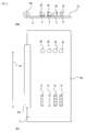
- the drum cartridge 8 has a photosensitive drum (photosensitive member) 1.
- the photosensitive drum 1 is charged with the surface of the drum by the charger 2 and is exposed by the exposure device 3 to the laser light L based on the image information to form an electrostatic latent image.
- the electrostatic latent image is developed as a toner image of each color using toner of each color of yellow, magenta, cyan and black by the developing cartridges 4y to 4k.
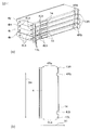
- the developed toner image is primarily transferred to the intermediate transfer belt 51 of the intermediate transfer unit 5.
- the transfer residual toner remaining on the photosensitive drum 1 after the primary transfer is cleaned by the drum cleaning device 6.
- the sheet S stacked on the feeding cassette 17 is conveyed to the nip portion between the secondary transfer roller 32 and the intermediate transfer belt 51 by the feeding roller 18 and the pair of registration rollers 19.
- the transferred toner image is secondarily transferred.
- the sheet S on which the toner image has been transferred has the toner image fixed by the fixing unit 20 and is discharged out of the apparatus main body by the discharge roller pair 23.
- the transfer residual toner remaining on the intermediate transfer belt 51 after the secondary transfer is cleaned by the belt cleaning device 7. (Replacing method of developing cartridges 4y to 4k)
- An opening 103 is provided on the front of the device body 101.
- the door 10 is pivoted relative to the apparatus main body 101 about a hinge shaft 10b on the lower side of the door, so that the opening 103 can be opened and closed.
- the developing cartridge attaching / detaching portion 102 is opened.
- FIG. 5 on the inner wall surfaces of the right side frame 105R and the left side frame 105L of the apparatus main body 101, four pairs of horizontally extending guide rails 25R, 25L are provided to face each other.
- guided portions 4Ra and 4La are provided on the left side and the right side of the developing cartridges 4y to 4k, respectively.
- the development cartridges 4y to 4k can be attached to and detached from the development cartridge attaching / detaching portion 102 by sliding the guide rails 25R and 25L in the horizontal direction (directions of arrows X1 and X2).
- a positioning and pressing portion (contact portion) 26 is provided on the inner surface 10 c inside the door 10.
- the pressing unit 26 presses the developing cartridges 4y to 4k in the direction (arrow X2 direction) pushing the developing cartridges 4y to 4k into the developing cartridge attachment / detachment unit 102 with the door 10 closed, and positions the developing cartridges 4y to 4k in the apparatus main body 101.
- (Drum cartridge 8 replacement method) As shown in FIG.
- the drum cartridge 8 is attached and detached in a state in which the developing cartridges 4y to 4k are removed with the door 10 opened as described above.
- the drum cartridge 8 is guided in the taking-out direction (X1 direction) or the mounting direction (X2 direction) by the left and right guide rails 27R and 27L provided on the bottom of the apparatus main body 101, and is attached to and detached from the drum cartridge attaching / detaching portion 104. . (Drum cartridge removal guide 28)
- drum cartridge mounting and demounting guides (mounting and demounting path regulating members) 28R and 28L are provided on the left and right.
- the drum cartridge mounting guides 28R and 28L are positioned at the center of gravity of the developing cartridges 4y to 4k in the removal direction. More than the door side is provided.
- the mounting and demounting guides 28R and 28L are spaced apart by a distance equal to or less than the width of the drum cartridge 8 in the width direction (the direction of the arrow X4).
- the attachment / detachment guides 28R and 28L have an inclined surface 28a inclined upward in the drum cartridge removal direction (direction X1) with the door 10 opened. As shown in FIG. 9, the slope 28a may be a curved surface as long as it is a gentle surface.
- the removable guides 28R and 28L have the same shape when viewed from the left side direction as shown in FIG. 8A, and are provided at the same position in the takeout direction (X1 direction). Therefore, the drum cartridge 8 simultaneously contacts the mounting and demounting guides 28R and 28L. Thereby, the drum cartridge 8 can be suppressed from being inclined. As shown in FIG. 8A, the detachable guides 28R and 28L contact with the contacts 14 (see FIG. 6) of the developing cartridges 4y to 4k when the door 10 is open, and the pressing portion It is provided on the inner side of the apparatus main body than 26.
- the developing cartridges 4y to 4k can be energized from the apparatus main body via the contacts 14, and operate in response to an electrical signal.
- the contact point 15 and the pressing portion 26 protrude from the door 10. Further, when the door 10 is viewed from the left side direction, the detachable guides 28R and 28L are higher than the contact point 15 and the pressing portion 26 (height in the arrow X3 direction).
- the drum cartridge 8 is taken out of the apparatus main body 101, when the drum cartridge 8 in the drum cartridge attaching / detaching portion 104 is pulled out, the lower end of the drum cartridge 8 contacts the inclined surface 28a of the attaching / detaching guides 28R, 28L.
- the drum cartridge 8 is moved along the inclined surface 28 a in a direction away from the contact 15 and the pressing portion 26 so that the drum cartridge 8 does not contact the contact 15 and the pressing portion 26.
- the mounting and demounting guides 28R and 28L restrict the drum cartridge 8 to pass through the path that does not interfere with the contact 15 and the pressing portion 26. Thereby, when removing the drum cartridge 8 from the image forming apparatus 100 which has been downsized, the drum cartridge 8 is prevented from coming into contact with the contact 15 and the pressing portion 26 of the door 10, and the contact 15 and the pressing portion 26 are damaged or broken. Can be suppressed.
- the number of the attachment and detachment guides 28R and 28L is not limited to two, and may be one or three or more.
- the width (the width in the direction of arrow X4) of the mounting and demounting guides 28R and 28L is not particularly limited, but a certain strength or more may be maintained so as not to be damaged even in contact with the drum cartridge 8 when the drum cartridge 8 is taken out. It has become possible width.
- the mounting and demounting guides 28R and 28L are described as regulating the drum cartridge 8.
- what the attachment and detachment guides 28R and 28L regulate is not limited to the drum cartridge, and may be a cartridge that can be attached to and detached from the apparatus main body such as the developing cartridges 4y to 4k.
- the drum cartridge 8 has a handle 8a and left and right escape portions 8Rd and 8Ld on a drawer member 8c extended to the side close to the opening 103.
- the relief portions 8Rd, 8Ld are provided by forming the drum cartridge 8 in a shape recessed from the end portion closer to the door 10.
- the width in the X4 direction of the relief portions 8Rd, 8Ld is larger than the width in the arrow X4 direction of the detachable guides 28R, 28L. Further, the width in the X1 direction of the relief portions 8Rd, 8Ld is larger than the height in the arrow X3 direction of the mounting and demounting guides 28R, 28L. As a result, when the door 10 is closed, the removable guides 28R, 28L can pass through the relief portions 8Rd, 8Ld, so that the removable guides 28R, 28L and the drum cartridge 8 do not interfere with each other.
- FIG. 12A is a side view of the door 10 according to the present embodiment.
- FIG. 12 (b) is a plan view of the door 10 according to the present embodiment.
- the image forming apparatus of this embodiment is provided with drum cartridge attaching and detaching guides 30R, 30L in place of the drum cartridge attaching and detaching guides 28R, 28L of the image forming apparatus of the first embodiment. .
- the detachable guides 30R, 30L are obtained by extending the detachable guides 28R, 28L in the pulling direction (arrow X1 direction).
- the flat portions 30b of the attachment and detachment guides 30R and 30L have a length that covers all of the four contact points 15 and the pressing portion 26 in the extraction direction for taking out the drum cartridge 8.
- the attachment / detachment guides 30R and 30L are provided outside the contact point 15 and the pressing part 26 in the width direction (direction of arrow X4), but may be provided inside.
- the mounting and demounting guides 30R and 30L are provided at a distance equal to or less than the width of the drum cartridge 8 in the width direction (the direction of the arrow X4).
- the removable guides 30R and 30L have the same shape, and are provided at the same position in the removal direction (direction X1). Therefore, the drum cartridge 8 simultaneously contacts the mounting and demounting guides 30R and 30L. Thereby, the drum cartridge 8 can be suppressed from being inclined.
- the attachment / detachment guides 30R, 30L have an inclined surface 30a inclined upward in the drum cartridge removal direction (X1 direction) with the door 10 opened.
- the attachment / detachment guides 30R, 30L are higher in the arrow X3 direction than the contact point 15 and the pressing portion 26.
- the drum cartridge 8 has a configuration different from the relief portions 8Rd and 8Ld of the first embodiment.
- the relief portions 8Rd, 8Ld are configured to allow the removable guides 30R, 30L to pass when the door 10 is closed, so that the removable cartridges 30R, 30L and the drum cartridge 8 do not interfere with each other. As shown in FIG.
- the developing cartridges 4y to 4k of the present embodiment have relief portions 4Rb and 4Lb on the left and right sides on the surface that becomes the outer side of the apparatus main body in the state of being mounted on the apparatus main body.
- the mounting and demounting guides 30R and 30L pass through the relief portions 4Rb and 4Lb, and the mounting and demounting guides 30R and 30L do not interfere with the developing cartridges 4y to 4k.
- FIG. 15A is a side view of the drum cartridge 8 according to the present embodiment.
- FIG. 15B is a front view of the drum cartridge 8 according to the present embodiment.
- (Drum cartridge leg 8f) As shown in FIG. 15, in the image forming apparatus of the present embodiment, the portions where the drum cartridge mounting and demounting guides 28R and 28L are provided are changed from the door inner surface 10c to the drum cartridge lower surface 8e to form drum cartridge legs 8Rf and 8Lf.
- the drum cartridge legs 8Rf and 8Lf are disposed closer to the door 10 when the drum cartridge 8 is attached to the apparatus main body 101.
- the leg portions 8Rf and 8Lf are provided at the positions coinciding with the end of the drum cartridge 8 in the removal direction (X1 direction).
- the legs 8Rf and 8Lf may be provided at other positions as long as the drum cartridge 8 can be prevented from being inclined when the drum cartridge 8 is pulled out from the main body 101.
- the height of the drum cartridge legs 8Rf and 8Lf in the X3 direction is such that the drum cartridge 8 does not contact the contact point 15 on the door and the positioning pressing portion 26 when the drum cartridge 8 is inclined and supported by the drum cartridge legs 8Rf and 8Lf. It is larger than the contact point 15 and the pressing part 26.
- the leg lower surface 8Rg ⁇ 8Lg may not be a flat surface parallel to the bottom surface 8e, as long as the drum cartridge 8 can be supported without being tilted. It may be a curved surface. As shown in FIG. 15B, the distance between the drum cartridge legs 8Rf and 8Lf is greater than the width of the hinge shaft 10b of the door 10 shown in FIG. 16B in the X4 direction. Although two legs 8Rf and 8Lf are provided in this embodiment, one or three legs 8Rf and 8Lf are not in contact with the hinge shaft 10b of the door 10 when the drum cartridge 8 is taken out of the apparatus main body 101. It may be more than.
- the hinge axis of the door may be two or more.
- the drum cartridge leg 8Rf is provided on the right side of the position of the positioning and pressing unit 26, and is provided such that the right end matches the right end of the drum cartridge 8.
- the width in the X4 direction of the leg portion 8Rf is not particularly limited, but the width can maintain a certain strength or more so as to have a supportable strength when the drum cartridge 8 is inclined.
- the right end of the leg 8Rf coincides with the right end of the drum cartridge 8. However, if the strength can be maintained and the drum cartridge 8 can be supported without being inclined, the two coincide. You do not have to.
- the leg portion 8Rf when the drum cartridge 8 is attached to the apparatus main body 101, the leg portion 8Rf is disposed on the right side from the position of the pressing portion 26, but it is possible to support the drum cartridge 8 without tilting. , And may be disposed on the left side of the pressing unit 26.
- the drum cartridge leg 8Lf is provided on the left side of the position of the contact 15 when the drum cartridge 8 is viewed from the front direction, and the left end and the left end of the drum cartridge 8 are aligned.
- the width of the leg portion 8Lf in the X4 direction is not particularly limited, but the width can maintain a certain strength or more so as to have a supportable strength when the drum cartridge 8 is inclined.
- the left end of the leg portion 8Lf coincides with the left end of the drum cartridge 8. However, if the strength can be maintained and the drum cartridge 8 can be supported without being inclined, they coincide with each other. You do not have to. Further, in the present embodiment, when the drum cartridge 8 is attached to the apparatus main body 101, the leg 8Lf is disposed on the left side from the position of the contact 15, but if the drum cartridge 8 can be supported without being inclined, It may be disposed to the right of the contact 15. The drum cartridge 8 is supported by the lower surface 8e of the drum cartridge in contact with the apparatus body 101 before and immediately after taking it out of the apparatus body 101.
- a pair of drum cartridge legs 8Rf and 8Lf is provided at the end of the lower surface 8e in the takeout direction (X1 direction). As shown in), a pair may be further provided at the end in the mounting direction (X2 direction).
- the legs 8Rf and 8Lf at the end in the removal direction (X1 direction) are separated from the door surface 10c and can not support the drum cartridge 8. Since the legs 8Rf and 8Lf at the end in the mounting direction (X2 direction) can be supported, the contact between the drum cartridge 8 and the contact 15 and the pressing portion 26 can be further avoided.
- the width of the drum cartridge legs 8Rf and 8Lf in the X1 direction is not particularly limited as long as the drum cartridge 8 can be supported without being tilted, but as shown in FIG.
- the drum cartridge legs 8Rf and 8Lf described in the present embodiment are not limited to the drum cartridge 8 as in the present embodiment. It may be another cartridge such as a developing cartridge. (Example of door configuration) In the present embodiment, the partial shapes of the door 10 and the door 10 b are changed. As shown in FIG.
- FIG. 18A is a perspective view of the image forming apparatus according to the present embodiment.
- FIG. 18A is a perspective view of the image forming apparatus according to the present embodiment.
- FIG. 1B is a block diagram of an image forming apparatus according to the present embodiment.
- the image forming apparatus 100 of the present embodiment has an all-in-one cartridge (process cartridge) 9 having a developing device and a drum.
- the all-in-one cartridge 9 is detachably mounted to the all-in-one cartridge attaching / detaching portion 106 of the image forming apparatus main body 101 with the door 10 opened.
- the all-in-one cartridge 9 has a photosensitive drum 1.
- the photosensitive drum 1 is charged with the surface of the drum by the charger 2 and is exposed by the exposure device 3 to the laser light L based on the image information to form an electrostatic latent image.
- the electrostatic latent image is developed as a toner image by the developing roller 4a using black toner.
- the sheet S stacked on the feeding cassette 17 is conveyed to the nip portion between the transfer roller 32 and the photosensitive drum 1 by the feeding roller 18 and the registration roller pair 19, and the toner image transferred to the photosensitive drum 1 is Transcribed.
- the sheet S on which the toner image has been transferred has the toner image fixed by the fixing unit 20 and is discharged out of the apparatus main body by the discharge roller pair 23. Further, the transfer residual toner remaining on the photosensitive drum 1 is cleaned by the drum cleaning device 6.
- a positioning pressing portion (contact portion) 26 is provided on the inner surface 10 c of the door 10. With the door 10 closed, the pressing portion 26 presses the all-in-one cartridge 9 into the all-in-one cartridge mounting portion 106 in the direction (arrow X2 direction) to position the all-in-one cartridge 9 in the apparatus main body 101.
- All-in-one cartridge removal guide 28 As shown in FIGS. 19, 21 and 22, on the inner surface 10c of the door 10, all-in-one cartridge mounting and demounting guides (mounting and demounting path regulating members) 28R and 28L are provided on the left and right.
- the all-in-one cartridge mounting and demounting guides 28R and 28L change the target to be guided from the above-described first embodiment from the drum cartridge 8 to the all-in-one cartridge 9, but the configuration is the same as the drum cartridge mounting and demounting guides 28R and 28L.
- the drum cartridge 8 is changed from the drum cartridge 8 to the all-in-one cartridge 9 as to the object of the effect in the present embodiment, the contents of the effect are the same as those of the first embodiment.
- the all-in-one cartridge 9 has a handle 9b and left and right escape portions 9Rd and 9Ld on a drawer member 9a extended to the side close to the opening 103.
- the width in the X4 direction of the relief portions 9Rd, 9Ld is larger than the width in the arrow X4 direction of the detachable guides 28R, 28L. Further, the width in the X1 direction of the relief portions 9Rd and 9Ld is larger than the height in the arrow X3 direction of the detachable guides 28R and 28L. As a result, when the door 10 is closed, the removable guides 28R and 28L can pass through the relief portions 9Rd and 9Ld, so that the removable guides 28R and 28L do not interfere with the all-in-one cartridge 9.
- the image forming apparatus of this embodiment is provided with all-in-one cartridge mounting and dismounting guides 30R and 30L in place of the all-in-one cartridge mounting and dismounting guides 28R and 28L of the image forming apparatus of the fourth embodiment. .
- the all-in-one cartridge mounting and demounting guides 30R and 30L change the target to be guided from the second embodiment to the all-in-one cartridge 9 from the drum cartridge 8, the configuration is the same as the drum mounting and demounting guides 28R and 28L.
- the drum cartridge 8 is changed to the all-in-one cartridge 9 with respect to the target of the effect in the present embodiment, the contents of the effect are the same as those of the second embodiment.
- the configuration of the all-in-one cartridge 9 is changed from the escape portions 9Rd and 9Ld of the fourth embodiment.
- FIG. 26 (a) is a side view of the all-in-one cartridge 9 according to this embodiment.
- FIG. 26B is a front view of the all-in-one cartridge 9 according to the present embodiment. (All-in-one cartridge leg 9f) As shown in FIG.
- the all-in-one cartridge mounting / dismounting guides 30R, 30L are changed from the door inner surface 10c to the all-in-one cartridge lower surface 9e to form all-in-one cartridge leg portions 9Rf, 9Lf.
- the target to be guided from the third embodiment is changed from the drum cartridge 8 to the all-in-one cartridge 9, the configuration is the same as that of the drum cartridge legs 8Rf and 8Lf.
- the drum cartridge 8 is changed to the all-in-one cartridge 9 with regard to the object of the effect in the present embodiment, the contents of the effect are the same as those of the third embodiment.
- the user can easily carry out without damaging the pressing portion and the contact on the door.
- the cartridge can be removed from the device body.
- a forming device is provided.
Landscapes
- Physics & Mathematics (AREA)
- General Physics & Mathematics (AREA)
- Electrophotography Configuration And Component (AREA)
Priority Applications (3)
| Application Number | Priority Date | Filing Date | Title |
|---|---|---|---|
| US13/554,570 US8666278B2 (en) | 2010-08-19 | 2012-07-20 | Image forming apparatus having a door path regulating member |
| US14/054,990 US8737872B2 (en) | 2010-08-19 | 2013-10-16 | Image forming apparatus having a door path regulating member |
| US14/247,348 US8983334B2 (en) | 2010-08-19 | 2014-04-08 | Image forming apparatus having a path regulating member |
Applications Claiming Priority (2)
| Application Number | Priority Date | Filing Date | Title |
|---|---|---|---|
| JP2010183956A JP5653127B2 (ja) | 2010-08-19 | 2010-08-19 | 画像形成装置 |
| JP2010-183956 | 2010-08-19 |
Related Child Applications (1)
| Application Number | Title | Priority Date | Filing Date |
|---|---|---|---|
| US13/554,570 Continuation US8666278B2 (en) | 2010-08-19 | 2012-07-20 | Image forming apparatus having a door path regulating member |
Publications (1)
| Publication Number | Publication Date |
|---|---|
| WO2012023591A1 true WO2012023591A1 (ja) | 2012-02-23 |
Family
ID=45605244
Family Applications (1)
| Application Number | Title | Priority Date | Filing Date |
|---|---|---|---|
| PCT/JP2011/068720 Ceased WO2012023591A1 (ja) | 2010-08-19 | 2011-08-12 | 画像形成装置 |
Country Status (3)
| Country | Link |
|---|---|
| US (3) | US8666278B2 (enExample) |
| JP (1) | JP5653127B2 (enExample) |
| WO (1) | WO2012023591A1 (enExample) |
Families Citing this family (15)
| Publication number | Priority date | Publication date | Assignee | Title |
|---|---|---|---|---|
| JP5653127B2 (ja) * | 2010-08-19 | 2015-01-14 | キヤノン株式会社 | 画像形成装置 |
| JP5836639B2 (ja) | 2011-05-17 | 2015-12-24 | キヤノン株式会社 | 画像形成装置 |
| JP5307200B2 (ja) | 2011-07-28 | 2013-10-02 | シャープ株式会社 | トナーカートリッジ支持装置とこれを用いる画像形成装置及びトナーカートリッジ支持方法 |
| US9182739B2 (en) | 2013-01-24 | 2015-11-10 | Samsung Electronics Co., Ltd. | Electrophotographic image forming apparatus |
| EP3193215B1 (en) | 2013-01-24 | 2020-03-25 | Hewlett-Packard Development Company, L.P. | Electrophotographic image forming apparatus and process cartridge |
| US9104169B2 (en) | 2013-01-24 | 2015-08-11 | Samsung Electronics Co., Ltd. | Electrophotographic image forming apparatus |
| KR101474306B1 (ko) | 2013-01-24 | 2014-12-18 | 삼성전자주식회사 | 전자사진방식 화상형성장치 및 현상 카트리지 |
| US9058017B2 (en) | 2013-01-24 | 2015-06-16 | Samsung Electronics Co., Ltd. | Electrophotographic image forming apparatus and development cartridge |
| EP2759888B1 (en) | 2013-01-24 | 2017-09-27 | S-Printing Solution Co., Ltd. | Electrophotographic image forming apparatus and development cartridge |
| CN203870397U (zh) * | 2014-04-12 | 2014-10-08 | 珠海赛纳打印科技股份有限公司 | 一种电子成像装置 |
| JP6645683B2 (ja) | 2015-05-21 | 2020-02-14 | キヤノン株式会社 | 画像形成装置およびこれに用いられるカートリッジ |
| US10358826B1 (en) | 2018-04-10 | 2019-07-23 | Salvatore Loccisano | Weather overhang assembly |
| JP7651257B2 (ja) * | 2019-12-27 | 2025-03-26 | キヤノン株式会社 | 画像形成装置 |
| US11409225B2 (en) * | 2019-12-27 | 2022-08-09 | Canon Kabushiki Kaisha | Image forming apparatus with draw-out unit having electrically contactable contact pairs |
| JP7413016B2 (ja) * | 2019-12-27 | 2024-01-15 | キヤノン株式会社 | 画像形成装置 |
Citations (7)
| Publication number | Priority date | Publication date | Assignee | Title |
|---|---|---|---|---|
| JPH1026863A (ja) * | 1996-07-10 | 1998-01-27 | Canon Inc | 画像形成装置 |
| JP2001066968A (ja) * | 1999-08-31 | 2001-03-16 | Canon Inc | 画像形成装置 |
| JP2002072826A (ja) * | 2000-08-25 | 2002-03-12 | Ricoh Co Ltd | 画像形成装置 |
| JP2002207408A (ja) * | 2001-01-10 | 2002-07-26 | Canon Inc | 電子写真画像形成装置及びプロセスカートリッジ |
| JP2006098772A (ja) * | 2004-09-29 | 2006-04-13 | Brother Ind Ltd | 画像形成装置及び画像形成ユニット |
| JP2007193125A (ja) * | 2006-01-19 | 2007-08-02 | Brother Ind Ltd | カートリッジ及び画像形成装置 |
| JP2007333817A (ja) * | 2006-06-12 | 2007-12-27 | Ricoh Co Ltd | 画像形成装置 |
Family Cites Families (20)
| Publication number | Priority date | Publication date | Assignee | Title |
|---|---|---|---|---|
| JP4296497B2 (ja) * | 2004-02-27 | 2009-07-15 | ブラザー工業株式会社 | 画像形成装置 |
| US7139507B2 (en) * | 2004-03-22 | 2006-11-21 | Fuji Xerox Co. Ltd. | Image forming apparatus and method of mounting and demounting process cartridge |
| US7778567B2 (en) | 2004-09-29 | 2010-08-17 | Brother Kogyo Kabushiki Kaisha | Image forming apparatus and image forming unit |
| JP4687387B2 (ja) * | 2005-10-26 | 2011-05-25 | ブラザー工業株式会社 | 画像形成装置及び作像カートリッジ |
| US7840154B2 (en) * | 2007-02-20 | 2010-11-23 | Brother Kogyo Kabushiki Kaisha | Image forming device and cartridge |
| JP5230265B2 (ja) * | 2008-05-23 | 2013-07-10 | キヤノン株式会社 | 画像形成装置及びプロセスカートリッジ |
| JP4384251B1 (ja) | 2009-03-11 | 2009-12-16 | キヤノン株式会社 | 現像カートリッジ、プロセスカートリッジ、及び電子写真画像形成装置 |
| JP4569977B1 (ja) | 2009-03-23 | 2010-10-27 | キヤノン株式会社 | 電子写真画像形成装置 |
| JP4605821B2 (ja) | 2009-03-23 | 2011-01-05 | キヤノン株式会社 | 電子写真画像形成装置 |
| JP4569978B1 (ja) | 2009-03-23 | 2010-10-27 | キヤノン株式会社 | カラー電子写真画像形成装置 |
| JP4562208B1 (ja) | 2009-03-23 | 2010-10-13 | キヤノン株式会社 | カラー電子写真画像形成装置 |
| JP4721471B2 (ja) | 2009-03-23 | 2011-07-13 | キヤノン株式会社 | 電子写真画像形成装置 |
| JP4846033B2 (ja) | 2009-03-26 | 2011-12-28 | キヤノン株式会社 | 電子写真画像形成装置 |
| KR101636550B1 (ko) * | 2009-09-28 | 2016-07-06 | 삼성전자 주식회사 | 화상형성장치 |
| KR101720185B1 (ko) * | 2009-10-15 | 2017-03-28 | 에스프린팅솔루션 주식회사 | 화상형성장치 |
| JP5220084B2 (ja) | 2009-12-11 | 2013-06-26 | キヤノン株式会社 | 電子写真画像形成装置 |
| JP4678891B1 (ja) | 2010-07-05 | 2011-04-27 | キヤノン株式会社 | 電子写真画像形成装置 |
| JP5653127B2 (ja) * | 2010-08-19 | 2015-01-14 | キヤノン株式会社 | 画像形成装置 |
| JP5350455B2 (ja) | 2010-12-16 | 2013-11-27 | キヤノン株式会社 | 電子写真画像形成装置 |
| JP5836639B2 (ja) | 2011-05-17 | 2015-12-24 | キヤノン株式会社 | 画像形成装置 |
-
2010
- 2010-08-19 JP JP2010183956A patent/JP5653127B2/ja active Active
-
2011
- 2011-08-12 WO PCT/JP2011/068720 patent/WO2012023591A1/ja not_active Ceased
-
2012
- 2012-07-20 US US13/554,570 patent/US8666278B2/en active Active
-
2013
- 2013-10-16 US US14/054,990 patent/US8737872B2/en not_active Expired - Fee Related
-
2014
- 2014-04-08 US US14/247,348 patent/US8983334B2/en active Active
Patent Citations (7)
| Publication number | Priority date | Publication date | Assignee | Title |
|---|---|---|---|---|
| JPH1026863A (ja) * | 1996-07-10 | 1998-01-27 | Canon Inc | 画像形成装置 |
| JP2001066968A (ja) * | 1999-08-31 | 2001-03-16 | Canon Inc | 画像形成装置 |
| JP2002072826A (ja) * | 2000-08-25 | 2002-03-12 | Ricoh Co Ltd | 画像形成装置 |
| JP2002207408A (ja) * | 2001-01-10 | 2002-07-26 | Canon Inc | 電子写真画像形成装置及びプロセスカートリッジ |
| JP2006098772A (ja) * | 2004-09-29 | 2006-04-13 | Brother Ind Ltd | 画像形成装置及び画像形成ユニット |
| JP2007193125A (ja) * | 2006-01-19 | 2007-08-02 | Brother Ind Ltd | カートリッジ及び画像形成装置 |
| JP2007333817A (ja) * | 2006-06-12 | 2007-12-27 | Ricoh Co Ltd | 画像形成装置 |
Also Published As
| Publication number | Publication date |
|---|---|
| US8983334B2 (en) | 2015-03-17 |
| US20140219678A1 (en) | 2014-08-07 |
| US8737872B2 (en) | 2014-05-27 |
| US20120294648A1 (en) | 2012-11-22 |
| US8666278B2 (en) | 2014-03-04 |
| JP2012042725A (ja) | 2012-03-01 |
| JP5653127B2 (ja) | 2015-01-14 |
| US20140037330A1 (en) | 2014-02-06 |
Similar Documents
| Publication | Publication Date | Title |
|---|---|---|
| WO2012023591A1 (ja) | 画像形成装置 | |
| JP5836639B2 (ja) | 画像形成装置 | |
| JP4709133B2 (ja) | 電子写真画像形成装置 | |
| JP4818461B2 (ja) | 電子写真画像形成装置 | |
| CN102165379B (zh) | 彩色电子照相图像形成装置 | |
| EP3992726B1 (en) | Image forming apparatus | |
| JP4334014B1 (ja) | カラー電子写真画像形成装置 | |
| JP2009128506A (ja) | 画像形成装置 | |
| US12189332B2 (en) | Image forming apparatus having a drawer | |
| JP2010266854A (ja) | 電子写真画像形成装置、プロセスカートリッジ、及び、現像カートリッジ | |
| US9696685B2 (en) | Image forming apparatus having cartridges | |
| JP2008292804A (ja) | 電子写真画像形成装置 | |
| US8725057B2 (en) | Image formation apparatus | |
| CN114077181B (zh) | 成像设备 | |
| JP4769699B2 (ja) | 電子写真画像形成装置 | |
| JP5430784B2 (ja) | 電子写真画像形成装置 | |
| JP4645745B2 (ja) | 画像形成装置 |
Legal Events
| Date | Code | Title | Description |
|---|---|---|---|
| 121 | Ep: the epo has been informed by wipo that ep was designated in this application |
Ref document number: 11818232 Country of ref document: EP Kind code of ref document: A1 |
|
| NENP | Non-entry into the national phase |
Ref country code: DE |
|
| 122 | Ep: pct application non-entry in european phase |
Ref document number: 11818232 Country of ref document: EP Kind code of ref document: A1 |