WO2012023591A1 - 画像形成装置 - Google Patents
画像形成装置 Download PDFInfo
- Publication number
- WO2012023591A1 WO2012023591A1 PCT/JP2011/068720 JP2011068720W WO2012023591A1 WO 2012023591 A1 WO2012023591 A1 WO 2012023591A1 JP 2011068720 W JP2011068720 W JP 2011068720W WO 2012023591 A1 WO2012023591 A1 WO 2012023591A1
- Authority
- WO
- WIPO (PCT)
- Prior art keywords
- cartridge
- door
- image forming
- forming apparatus
- contact portion
- Prior art date
Links
Images


Classifications
-
- G—PHYSICS
- G03—PHOTOGRAPHY; CINEMATOGRAPHY; ANALOGOUS TECHNIQUES USING WAVES OTHER THAN OPTICAL WAVES; ELECTROGRAPHY; HOLOGRAPHY
- G03G—ELECTROGRAPHY; ELECTROPHOTOGRAPHY; MAGNETOGRAPHY
- G03G21/00—Arrangements not provided for by groups G03G13/00 - G03G19/00, e.g. cleaning, elimination of residual charge
- G03G21/16—Mechanical means for facilitating the maintenance of the apparatus, e.g. modular arrangements
- G03G21/1661—Mechanical means for facilitating the maintenance of the apparatus, e.g. modular arrangements means for handling parts of the apparatus in the apparatus
- G03G21/1671—Mechanical means for facilitating the maintenance of the apparatus, e.g. modular arrangements means for handling parts of the apparatus in the apparatus for the photosensitive element
-
- G—PHYSICS
- G03—PHOTOGRAPHY; CINEMATOGRAPHY; ANALOGOUS TECHNIQUES USING WAVES OTHER THAN OPTICAL WAVES; ELECTROGRAPHY; HOLOGRAPHY
- G03G—ELECTROGRAPHY; ELECTROPHOTOGRAPHY; MAGNETOGRAPHY
- G03G21/00—Arrangements not provided for by groups G03G13/00 - G03G19/00, e.g. cleaning, elimination of residual charge
- G03G21/16—Mechanical means for facilitating the maintenance of the apparatus, e.g. modular arrangements
- G03G21/1604—Arrangement or disposition of the entire apparatus
-
- G—PHYSICS
- G03—PHOTOGRAPHY; CINEMATOGRAPHY; ANALOGOUS TECHNIQUES USING WAVES OTHER THAN OPTICAL WAVES; ELECTROGRAPHY; HOLOGRAPHY
- G03G—ELECTROGRAPHY; ELECTROPHOTOGRAPHY; MAGNETOGRAPHY
- G03G15/00—Apparatus for electrographic processes using a charge pattern
- G03G15/06—Apparatus for electrographic processes using a charge pattern for developing
- G03G15/08—Apparatus for electrographic processes using a charge pattern for developing using a solid developer, e.g. powder developer
- G03G15/0822—Arrangements for preparing, mixing, supplying or dispensing developer
- G03G15/0863—Arrangements for preparing, mixing, supplying or dispensing developer provided with identifying means or means for storing process- or use parameters, e.g. an electronic memory
-
- G—PHYSICS
- G03—PHOTOGRAPHY; CINEMATOGRAPHY; ANALOGOUS TECHNIQUES USING WAVES OTHER THAN OPTICAL WAVES; ELECTROGRAPHY; HOLOGRAPHY
- G03G—ELECTROGRAPHY; ELECTROPHOTOGRAPHY; MAGNETOGRAPHY
- G03G21/00—Arrangements not provided for by groups G03G13/00 - G03G19/00, e.g. cleaning, elimination of residual charge
- G03G21/16—Mechanical means for facilitating the maintenance of the apparatus, e.g. modular arrangements
- G03G21/1604—Arrangement or disposition of the entire apparatus
- G03G21/1623—Means to access the interior of the apparatus
- G03G21/1633—Means to access the interior of the apparatus using doors or covers
-
- G—PHYSICS
- G03—PHOTOGRAPHY; CINEMATOGRAPHY; ANALOGOUS TECHNIQUES USING WAVES OTHER THAN OPTICAL WAVES; ELECTROGRAPHY; HOLOGRAPHY
- G03G—ELECTROGRAPHY; ELECTROPHOTOGRAPHY; MAGNETOGRAPHY
- G03G21/00—Arrangements not provided for by groups G03G13/00 - G03G19/00, e.g. cleaning, elimination of residual charge
- G03G21/16—Mechanical means for facilitating the maintenance of the apparatus, e.g. modular arrangements
- G03G21/1661—Mechanical means for facilitating the maintenance of the apparatus, e.g. modular arrangements means for handling parts of the apparatus in the apparatus
- G03G21/1676—Mechanical means for facilitating the maintenance of the apparatus, e.g. modular arrangements means for handling parts of the apparatus in the apparatus for the developer unit
-
- G—PHYSICS
- G03—PHOTOGRAPHY; CINEMATOGRAPHY; ANALOGOUS TECHNIQUES USING WAVES OTHER THAN OPTICAL WAVES; ELECTROGRAPHY; HOLOGRAPHY
- G03G—ELECTROGRAPHY; ELECTROPHOTOGRAPHY; MAGNETOGRAPHY
- G03G2215/00—Apparatus for electrophotographic processes
- G03G2215/06—Developing structures, details
- G03G2215/066—Toner cartridge or other attachable and detachable container for supplying developer material to replace the used material
- G03G2215/0695—Toner cartridge or other attachable and detachable container for supplying developer material to replace the used material using identification means or means for storing process or use parameters
- G03G2215/0697—Toner cartridge or other attachable and detachable container for supplying developer material to replace the used material using identification means or means for storing process or use parameters being an electronically readable memory
-
- G—PHYSICS
- G03—PHOTOGRAPHY; CINEMATOGRAPHY; ANALOGOUS TECHNIQUES USING WAVES OTHER THAN OPTICAL WAVES; ELECTROGRAPHY; HOLOGRAPHY
- G03G—ELECTROGRAPHY; ELECTROPHOTOGRAPHY; MAGNETOGRAPHY
- G03G2221/00—Processes not provided for by group G03G2215/00, e.g. cleaning or residual charge elimination
- G03G2221/16—Mechanical means for facilitating the maintenance of the apparatus, e.g. modular arrangements and complete machine concepts
- G03G2221/1651—Mechanical means for facilitating the maintenance of the apparatus, e.g. modular arrangements and complete machine concepts for connecting the different parts
- G03G2221/1654—Locks and means for positioning or alignment
-
- G—PHYSICS
- G03—PHOTOGRAPHY; CINEMATOGRAPHY; ANALOGOUS TECHNIQUES USING WAVES OTHER THAN OPTICAL WAVES; ELECTROGRAPHY; HOLOGRAPHY
- G03G—ELECTROGRAPHY; ELECTROPHOTOGRAPHY; MAGNETOGRAPHY
- G03G2221/00—Processes not provided for by group G03G2215/00, e.g. cleaning or residual charge elimination
- G03G2221/16—Mechanical means for facilitating the maintenance of the apparatus, e.g. modular arrangements and complete machine concepts
- G03G2221/1678—Frame structures
- G03G2221/169—Structural door designs
Definitions
- the present invention relates to an image forming apparatus such as a copying machine and a facsimile.
- an image forming apparatus main body a door that can be opened and closed with respect to it, and a first cartridge that can be attached to and detached from the image forming apparatus main body when the door is opened;
- An image forming apparatus having a second cartridge removable above the cartridge, the door including a contact portion contacting the second cartridge in a state where the door is closed;
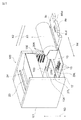
- FIG. 1A is a perspective view of the image forming apparatus according to the first embodiment.
- FIG. 1B is a block diagram of the image forming apparatus according to the first embodiment.
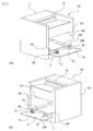
- FIG. 2 is a perspective view of the image forming apparatus according to the first embodiment with the door opened.
- FIG. 3 is a view for explaining attachment and detachment of the developing cartridge according to the first embodiment.
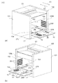
- FIG. 4 is a perspective view of the image forming apparatus in a state in which the developing cartridge according to the first embodiment is removed.
- FIG. 5 is a perspective view of the image forming apparatus from which the cartridge according to the first embodiment is removed.
- FIG. 6 is a perspective view of the developing cartridge according to the first embodiment.
- FIG. 7 is a view for explaining attachment and detachment of the drum cartridge according to the first embodiment.
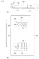
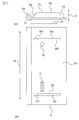
- FIG. 8A is a left side view of the door according to the first embodiment.
- FIG. 8B is a top view of the door according to the first embodiment.
- FIG. 9 is a left side view of a door having an attachment / detachment path restricting member of another shape.
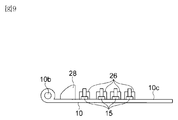
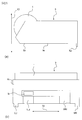
- FIG. 10 is a perspective view of the drum cartridge according to the first embodiment.
- FIG. 11 is a top view of the relief portion of the drum cartridge according to the first embodiment.
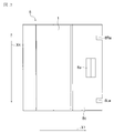
- FIG. 12A is a left side view of the door according to the second embodiment.
- FIG. 12 (b) is a top view of the door according to the second embodiment.
- FIG. 13 is a top view of the drum cartridge according to the second embodiment.
- FIG. 14A is a perspective view of the developing cartridge according to the second embodiment.
- FIG. 14B is a top view of the developing cartridge according to the second embodiment.
- FIG. 15A is a left side view of the drum cartridge according to the third embodiment.
- FIG. 15B is a front view of the drum cartridge according to the third embodiment.
- FIG. 16A is a left side view of the door according to the third embodiment.
- FIG. 16B is a top view of the door according to the third embodiment.
- FIGS. 17A and 17B are left side views showing one form of the drum cartridge according to the third embodiment.
- FIG. 18A is a perspective view of the image forming apparatus according to the fourth embodiment.
- FIG. 18B is a block diagram of an image forming apparatus according to the fourth embodiment.
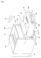
- FIG. 19 is a perspective view of the image forming apparatus according to the fourth embodiment with the door opened.
- FIG. 20 is a view for explaining attachment and detachment of the all-in-one cartridge according to the fourth embodiment.
- FIG. 21 is a perspective view of the image forming apparatus with the all-in-one cartridge according to the fourth embodiment removed.
- FIG. 22A is a left side view of the door according to the fourth embodiment.
- FIG. 22B is a top view of the door according to the fourth embodiment.
- FIG. 23 is a perspective view of the all-in-one cartridge according to the fourth embodiment.
- FIG. 24A is a left side view of the door according to the fifth embodiment.
- FIG. 24 (b) is a top view of the door according to the fifth embodiment.
- FIG. 25 is a top view of the all-in-one cartridge according to the fifth embodiment.
- FIG. 26A is a left side view of the all-in-one cartridge according to the sixth embodiment.
- FIG. 26B is a front view of the all-in-one cartridge according to the sixth embodiment.
- FIG. 1A is a perspective view of an image forming apparatus according to the present embodiment.
- FIG. 1B is a block diagram of an image forming apparatus according to the present embodiment.
- the image forming apparatus 100 of the present embodiment has developing cartridges (second cartridges) 4 y, 4 m, 4 c, 4 k and a drum cartridge (first cartridge) 8.
- the developing cartridges 4y to 4k are removably mounted on the developing cartridge mounting portion 102 of the image forming apparatus main body 101 with the door 10 opened.
- FIG. 1 is a perspective view of an image forming apparatus according to the present embodiment.
- FIG. 1B is a block diagram of an image forming apparatus according to the present embodiment.
- the image forming apparatus 100 of the present embodiment has developing cartridges (second cartridges) 4 y, 4 m, 4 c, 4 k and a drum cartridge (first cartridge) 8.
- the developing cartridges 4y to 4k are removably mounted on the developing cartridge mounting portion 102 of the image forming apparatus main body
- the drum cartridge 8 has a photosensitive drum (photosensitive member) 1.
- the photosensitive drum 1 is charged with the surface of the drum by the charger 2 and is exposed by the exposure device 3 to the laser light L based on the image information to form an electrostatic latent image.
- the electrostatic latent image is developed as a toner image of each color using toner of each color of yellow, magenta, cyan and black by the developing cartridges 4y to 4k.
- the developed toner image is primarily transferred to the intermediate transfer belt 51 of the intermediate transfer unit 5.
- the transfer residual toner remaining on the photosensitive drum 1 after the primary transfer is cleaned by the drum cleaning device 6.
- the sheet S stacked on the feeding cassette 17 is conveyed to the nip portion between the secondary transfer roller 32 and the intermediate transfer belt 51 by the feeding roller 18 and the pair of registration rollers 19.
- the transferred toner image is secondarily transferred.
- the sheet S on which the toner image has been transferred has the toner image fixed by the fixing unit 20 and is discharged out of the apparatus main body by the discharge roller pair 23.
- the transfer residual toner remaining on the intermediate transfer belt 51 after the secondary transfer is cleaned by the belt cleaning device 7. (Replacing method of developing cartridges 4y to 4k)
- An opening 103 is provided on the front of the device body 101.
- the door 10 is pivoted relative to the apparatus main body 101 about a hinge shaft 10b on the lower side of the door, so that the opening 103 can be opened and closed.
- the developing cartridge attaching / detaching portion 102 is opened.
- FIG. 5 on the inner wall surfaces of the right side frame 105R and the left side frame 105L of the apparatus main body 101, four pairs of horizontally extending guide rails 25R, 25L are provided to face each other.
- guided portions 4Ra and 4La are provided on the left side and the right side of the developing cartridges 4y to 4k, respectively.
- the development cartridges 4y to 4k can be attached to and detached from the development cartridge attaching / detaching portion 102 by sliding the guide rails 25R and 25L in the horizontal direction (directions of arrows X1 and X2).
- a positioning and pressing portion (contact portion) 26 is provided on the inner surface 10 c inside the door 10.
- the pressing unit 26 presses the developing cartridges 4y to 4k in the direction (arrow X2 direction) pushing the developing cartridges 4y to 4k into the developing cartridge attachment / detachment unit 102 with the door 10 closed, and positions the developing cartridges 4y to 4k in the apparatus main body 101.
- (Drum cartridge 8 replacement method) As shown in FIG.
- the drum cartridge 8 is attached and detached in a state in which the developing cartridges 4y to 4k are removed with the door 10 opened as described above.
- the drum cartridge 8 is guided in the taking-out direction (X1 direction) or the mounting direction (X2 direction) by the left and right guide rails 27R and 27L provided on the bottom of the apparatus main body 101, and is attached to and detached from the drum cartridge attaching / detaching portion 104. . (Drum cartridge removal guide 28)
- drum cartridge mounting and demounting guides (mounting and demounting path regulating members) 28R and 28L are provided on the left and right.
- the drum cartridge mounting guides 28R and 28L are positioned at the center of gravity of the developing cartridges 4y to 4k in the removal direction. More than the door side is provided.
- the mounting and demounting guides 28R and 28L are spaced apart by a distance equal to or less than the width of the drum cartridge 8 in the width direction (the direction of the arrow X4).
- the attachment / detachment guides 28R and 28L have an inclined surface 28a inclined upward in the drum cartridge removal direction (direction X1) with the door 10 opened. As shown in FIG. 9, the slope 28a may be a curved surface as long as it is a gentle surface.
- the removable guides 28R and 28L have the same shape when viewed from the left side direction as shown in FIG. 8A, and are provided at the same position in the takeout direction (X1 direction). Therefore, the drum cartridge 8 simultaneously contacts the mounting and demounting guides 28R and 28L. Thereby, the drum cartridge 8 can be suppressed from being inclined. As shown in FIG. 8A, the detachable guides 28R and 28L contact with the contacts 14 (see FIG. 6) of the developing cartridges 4y to 4k when the door 10 is open, and the pressing portion It is provided on the inner side of the apparatus main body than 26.
- the developing cartridges 4y to 4k can be energized from the apparatus main body via the contacts 14, and operate in response to an electrical signal.
- the contact point 15 and the pressing portion 26 protrude from the door 10. Further, when the door 10 is viewed from the left side direction, the detachable guides 28R and 28L are higher than the contact point 15 and the pressing portion 26 (height in the arrow X3 direction).
- the drum cartridge 8 is taken out of the apparatus main body 101, when the drum cartridge 8 in the drum cartridge attaching / detaching portion 104 is pulled out, the lower end of the drum cartridge 8 contacts the inclined surface 28a of the attaching / detaching guides 28R, 28L.
- the drum cartridge 8 is moved along the inclined surface 28 a in a direction away from the contact 15 and the pressing portion 26 so that the drum cartridge 8 does not contact the contact 15 and the pressing portion 26.
- the mounting and demounting guides 28R and 28L restrict the drum cartridge 8 to pass through the path that does not interfere with the contact 15 and the pressing portion 26. Thereby, when removing the drum cartridge 8 from the image forming apparatus 100 which has been downsized, the drum cartridge 8 is prevented from coming into contact with the contact 15 and the pressing portion 26 of the door 10, and the contact 15 and the pressing portion 26 are damaged or broken. Can be suppressed.
- the number of the attachment and detachment guides 28R and 28L is not limited to two, and may be one or three or more.
- the width (the width in the direction of arrow X4) of the mounting and demounting guides 28R and 28L is not particularly limited, but a certain strength or more may be maintained so as not to be damaged even in contact with the drum cartridge 8 when the drum cartridge 8 is taken out. It has become possible width.
- the mounting and demounting guides 28R and 28L are described as regulating the drum cartridge 8.
- what the attachment and detachment guides 28R and 28L regulate is not limited to the drum cartridge, and may be a cartridge that can be attached to and detached from the apparatus main body such as the developing cartridges 4y to 4k.
- the drum cartridge 8 has a handle 8a and left and right escape portions 8Rd and 8Ld on a drawer member 8c extended to the side close to the opening 103.
- the relief portions 8Rd, 8Ld are provided by forming the drum cartridge 8 in a shape recessed from the end portion closer to the door 10.
- the width in the X4 direction of the relief portions 8Rd, 8Ld is larger than the width in the arrow X4 direction of the detachable guides 28R, 28L. Further, the width in the X1 direction of the relief portions 8Rd, 8Ld is larger than the height in the arrow X3 direction of the mounting and demounting guides 28R, 28L. As a result, when the door 10 is closed, the removable guides 28R, 28L can pass through the relief portions 8Rd, 8Ld, so that the removable guides 28R, 28L and the drum cartridge 8 do not interfere with each other.
- FIG. 12A is a side view of the door 10 according to the present embodiment.
- FIG. 12 (b) is a plan view of the door 10 according to the present embodiment.
- the image forming apparatus of this embodiment is provided with drum cartridge attaching and detaching guides 30R, 30L in place of the drum cartridge attaching and detaching guides 28R, 28L of the image forming apparatus of the first embodiment. .
- the detachable guides 30R, 30L are obtained by extending the detachable guides 28R, 28L in the pulling direction (arrow X1 direction).
- the flat portions 30b of the attachment and detachment guides 30R and 30L have a length that covers all of the four contact points 15 and the pressing portion 26 in the extraction direction for taking out the drum cartridge 8.
- the attachment / detachment guides 30R and 30L are provided outside the contact point 15 and the pressing part 26 in the width direction (direction of arrow X4), but may be provided inside.
- the mounting and demounting guides 30R and 30L are provided at a distance equal to or less than the width of the drum cartridge 8 in the width direction (the direction of the arrow X4).
- the removable guides 30R and 30L have the same shape, and are provided at the same position in the removal direction (direction X1). Therefore, the drum cartridge 8 simultaneously contacts the mounting and demounting guides 30R and 30L. Thereby, the drum cartridge 8 can be suppressed from being inclined.
- the attachment / detachment guides 30R, 30L have an inclined surface 30a inclined upward in the drum cartridge removal direction (X1 direction) with the door 10 opened.
- the attachment / detachment guides 30R, 30L are higher in the arrow X3 direction than the contact point 15 and the pressing portion 26.
- the drum cartridge 8 has a configuration different from the relief portions 8Rd and 8Ld of the first embodiment.
- the relief portions 8Rd, 8Ld are configured to allow the removable guides 30R, 30L to pass when the door 10 is closed, so that the removable cartridges 30R, 30L and the drum cartridge 8 do not interfere with each other. As shown in FIG.
- the developing cartridges 4y to 4k of the present embodiment have relief portions 4Rb and 4Lb on the left and right sides on the surface that becomes the outer side of the apparatus main body in the state of being mounted on the apparatus main body.
- the mounting and demounting guides 30R and 30L pass through the relief portions 4Rb and 4Lb, and the mounting and demounting guides 30R and 30L do not interfere with the developing cartridges 4y to 4k.
- FIG. 15A is a side view of the drum cartridge 8 according to the present embodiment.
- FIG. 15B is a front view of the drum cartridge 8 according to the present embodiment.
- (Drum cartridge leg 8f) As shown in FIG. 15, in the image forming apparatus of the present embodiment, the portions where the drum cartridge mounting and demounting guides 28R and 28L are provided are changed from the door inner surface 10c to the drum cartridge lower surface 8e to form drum cartridge legs 8Rf and 8Lf.
- the drum cartridge legs 8Rf and 8Lf are disposed closer to the door 10 when the drum cartridge 8 is attached to the apparatus main body 101.
- the leg portions 8Rf and 8Lf are provided at the positions coinciding with the end of the drum cartridge 8 in the removal direction (X1 direction).
- the legs 8Rf and 8Lf may be provided at other positions as long as the drum cartridge 8 can be prevented from being inclined when the drum cartridge 8 is pulled out from the main body 101.
- the height of the drum cartridge legs 8Rf and 8Lf in the X3 direction is such that the drum cartridge 8 does not contact the contact point 15 on the door and the positioning pressing portion 26 when the drum cartridge 8 is inclined and supported by the drum cartridge legs 8Rf and 8Lf. It is larger than the contact point 15 and the pressing part 26.
- the leg lower surface 8Rg ⁇ 8Lg may not be a flat surface parallel to the bottom surface 8e, as long as the drum cartridge 8 can be supported without being tilted. It may be a curved surface. As shown in FIG. 15B, the distance between the drum cartridge legs 8Rf and 8Lf is greater than the width of the hinge shaft 10b of the door 10 shown in FIG. 16B in the X4 direction. Although two legs 8Rf and 8Lf are provided in this embodiment, one or three legs 8Rf and 8Lf are not in contact with the hinge shaft 10b of the door 10 when the drum cartridge 8 is taken out of the apparatus main body 101. It may be more than.
- the hinge axis of the door may be two or more.
- the drum cartridge leg 8Rf is provided on the right side of the position of the positioning and pressing unit 26, and is provided such that the right end matches the right end of the drum cartridge 8.
- the width in the X4 direction of the leg portion 8Rf is not particularly limited, but the width can maintain a certain strength or more so as to have a supportable strength when the drum cartridge 8 is inclined.
- the right end of the leg 8Rf coincides with the right end of the drum cartridge 8. However, if the strength can be maintained and the drum cartridge 8 can be supported without being inclined, the two coincide. You do not have to.
- the leg portion 8Rf when the drum cartridge 8 is attached to the apparatus main body 101, the leg portion 8Rf is disposed on the right side from the position of the pressing portion 26, but it is possible to support the drum cartridge 8 without tilting. , And may be disposed on the left side of the pressing unit 26.
- the drum cartridge leg 8Lf is provided on the left side of the position of the contact 15 when the drum cartridge 8 is viewed from the front direction, and the left end and the left end of the drum cartridge 8 are aligned.
- the width of the leg portion 8Lf in the X4 direction is not particularly limited, but the width can maintain a certain strength or more so as to have a supportable strength when the drum cartridge 8 is inclined.
- the left end of the leg portion 8Lf coincides with the left end of the drum cartridge 8. However, if the strength can be maintained and the drum cartridge 8 can be supported without being inclined, they coincide with each other. You do not have to. Further, in the present embodiment, when the drum cartridge 8 is attached to the apparatus main body 101, the leg 8Lf is disposed on the left side from the position of the contact 15, but if the drum cartridge 8 can be supported without being inclined, It may be disposed to the right of the contact 15. The drum cartridge 8 is supported by the lower surface 8e of the drum cartridge in contact with the apparatus body 101 before and immediately after taking it out of the apparatus body 101.
- a pair of drum cartridge legs 8Rf and 8Lf is provided at the end of the lower surface 8e in the takeout direction (X1 direction). As shown in), a pair may be further provided at the end in the mounting direction (X2 direction).
- the legs 8Rf and 8Lf at the end in the removal direction (X1 direction) are separated from the door surface 10c and can not support the drum cartridge 8. Since the legs 8Rf and 8Lf at the end in the mounting direction (X2 direction) can be supported, the contact between the drum cartridge 8 and the contact 15 and the pressing portion 26 can be further avoided.
- the width of the drum cartridge legs 8Rf and 8Lf in the X1 direction is not particularly limited as long as the drum cartridge 8 can be supported without being tilted, but as shown in FIG.
- the drum cartridge legs 8Rf and 8Lf described in the present embodiment are not limited to the drum cartridge 8 as in the present embodiment. It may be another cartridge such as a developing cartridge. (Example of door configuration) In the present embodiment, the partial shapes of the door 10 and the door 10 b are changed. As shown in FIG.
- FIG. 18A is a perspective view of the image forming apparatus according to the present embodiment.
- FIG. 18A is a perspective view of the image forming apparatus according to the present embodiment.
- FIG. 1B is a block diagram of an image forming apparatus according to the present embodiment.
- the image forming apparatus 100 of the present embodiment has an all-in-one cartridge (process cartridge) 9 having a developing device and a drum.
- the all-in-one cartridge 9 is detachably mounted to the all-in-one cartridge attaching / detaching portion 106 of the image forming apparatus main body 101 with the door 10 opened.
- the all-in-one cartridge 9 has a photosensitive drum 1.
- the photosensitive drum 1 is charged with the surface of the drum by the charger 2 and is exposed by the exposure device 3 to the laser light L based on the image information to form an electrostatic latent image.
- the electrostatic latent image is developed as a toner image by the developing roller 4a using black toner.
- the sheet S stacked on the feeding cassette 17 is conveyed to the nip portion between the transfer roller 32 and the photosensitive drum 1 by the feeding roller 18 and the registration roller pair 19, and the toner image transferred to the photosensitive drum 1 is Transcribed.
- the sheet S on which the toner image has been transferred has the toner image fixed by the fixing unit 20 and is discharged out of the apparatus main body by the discharge roller pair 23. Further, the transfer residual toner remaining on the photosensitive drum 1 is cleaned by the drum cleaning device 6.
- a positioning pressing portion (contact portion) 26 is provided on the inner surface 10 c of the door 10. With the door 10 closed, the pressing portion 26 presses the all-in-one cartridge 9 into the all-in-one cartridge mounting portion 106 in the direction (arrow X2 direction) to position the all-in-one cartridge 9 in the apparatus main body 101.
- All-in-one cartridge removal guide 28 As shown in FIGS. 19, 21 and 22, on the inner surface 10c of the door 10, all-in-one cartridge mounting and demounting guides (mounting and demounting path regulating members) 28R and 28L are provided on the left and right.
- the all-in-one cartridge mounting and demounting guides 28R and 28L change the target to be guided from the above-described first embodiment from the drum cartridge 8 to the all-in-one cartridge 9, but the configuration is the same as the drum cartridge mounting and demounting guides 28R and 28L.
- the drum cartridge 8 is changed from the drum cartridge 8 to the all-in-one cartridge 9 as to the object of the effect in the present embodiment, the contents of the effect are the same as those of the first embodiment.
- the all-in-one cartridge 9 has a handle 9b and left and right escape portions 9Rd and 9Ld on a drawer member 9a extended to the side close to the opening 103.
- the width in the X4 direction of the relief portions 9Rd, 9Ld is larger than the width in the arrow X4 direction of the detachable guides 28R, 28L. Further, the width in the X1 direction of the relief portions 9Rd and 9Ld is larger than the height in the arrow X3 direction of the detachable guides 28R and 28L. As a result, when the door 10 is closed, the removable guides 28R and 28L can pass through the relief portions 9Rd and 9Ld, so that the removable guides 28R and 28L do not interfere with the all-in-one cartridge 9.
- the image forming apparatus of this embodiment is provided with all-in-one cartridge mounting and dismounting guides 30R and 30L in place of the all-in-one cartridge mounting and dismounting guides 28R and 28L of the image forming apparatus of the fourth embodiment. .
- the all-in-one cartridge mounting and demounting guides 30R and 30L change the target to be guided from the second embodiment to the all-in-one cartridge 9 from the drum cartridge 8, the configuration is the same as the drum mounting and demounting guides 28R and 28L.
- the drum cartridge 8 is changed to the all-in-one cartridge 9 with respect to the target of the effect in the present embodiment, the contents of the effect are the same as those of the second embodiment.
- the configuration of the all-in-one cartridge 9 is changed from the escape portions 9Rd and 9Ld of the fourth embodiment.
- FIG. 26 (a) is a side view of the all-in-one cartridge 9 according to this embodiment.
- FIG. 26B is a front view of the all-in-one cartridge 9 according to the present embodiment. (All-in-one cartridge leg 9f) As shown in FIG.
- the all-in-one cartridge mounting / dismounting guides 30R, 30L are changed from the door inner surface 10c to the all-in-one cartridge lower surface 9e to form all-in-one cartridge leg portions 9Rf, 9Lf.
- the target to be guided from the third embodiment is changed from the drum cartridge 8 to the all-in-one cartridge 9, the configuration is the same as that of the drum cartridge legs 8Rf and 8Lf.
- the drum cartridge 8 is changed to the all-in-one cartridge 9 with regard to the object of the effect in the present embodiment, the contents of the effect are the same as those of the third embodiment.
- the user can easily carry out without damaging the pressing portion and the contact on the door.
- the cartridge can be removed from the device body.
- a forming device is provided.
Landscapes
- Physics & Mathematics (AREA)
- General Physics & Mathematics (AREA)
- Electrophotography Configuration And Component (AREA)
Abstract
画像形成装置本体に開閉可能なドア10と、ドア10を開いた状態で、画像形成装置本体に着脱可能なドラムカートリッジ8と、ドラムカートリッジ8の上方に着脱可能な現像カートリッジ4k~4yとを有し、ドア10は、ドア10を閉じた状態で、現像カートリッジ4k~4yと接触する位置決め押圧部26を有する画像形成装置において、ドア10は、ドラムカートリッジ8を画像形成装置から取り外す際に、ドラムカートリッジ8に当接して、ドラムカートリッジ8を位置決め押圧部26と干渉しない経路を通る様に規制するドラムカートリッジ着脱ガイド28R、28Lを有する。
Description
本発明は、複写機やファクシミリなどの画像形成装置に関するものである。
従来、感光ドラムを備えたドラムカートリッジや、現像ローラを備えた現像カートリッジのカートリッジを着脱可能としたプロセスカートリッジ方式の画像形成装置がある。例えば、米国特許7813670においては、装置本体に設けられたドアを開いて、カートリッジを取り外すことが可能である。また、ドアには、閉じた状態でカートリッジを押圧し、装置本体内に位置決めする位置決め押圧部が設けられている。このような画像形成装置は、感光ドラムと現像ローラを個別に交換できるため、感光ドラムと現像ローラとでは製品寿命が異なる場合などに有効である。
しかしながら、近年の画像形成装置の小型化に伴い、装置本体の高さを抑えたり、或は装置本体の幅方向の大きさを抑えたりする必要が生じてきている。それに伴い、装置本体からカートリッジを取り外す経路が狭くなってきている。
米国特許7813670では、装置の小型化に伴いカートリッジを取り外す経路が狭くなり、カートリッジを取り外す際に、カートリッジがドアの位置決め押圧部と接触し、位置決め押圧部の損傷や破損の原因となる可能性があった。
しかしながら、近年の画像形成装置の小型化に伴い、装置本体の高さを抑えたり、或は装置本体の幅方向の大きさを抑えたりする必要が生じてきている。それに伴い、装置本体からカートリッジを取り外す経路が狭くなってきている。
米国特許7813670では、装置の小型化に伴いカートリッジを取り外す経路が狭くなり、カートリッジを取り外す際に、カートリッジがドアの位置決め押圧部と接触し、位置決め押圧部の損傷や破損の原因となる可能性があった。
本発明の一形態においては、画像形成装置本体と、それに対して開閉可能なドアと、前記ドアを開いた状態で、前記画像形成装置本体に着脱可能な第1のカートリッジと、前記第1のカートリッジの上方に着脱可能な第2のカートリッジとを有し、前記ドアは、前記ドアを閉じた状態で、前記第2のカートリッジと接触する接触部を有する画像形成装置において、前記ドアは、前記第1のカートリッジを前記画像形成装置から取り外す際に、前記第1のカートリッジに当接して、前記第1のカートリッジを前記接触部と干渉しない経路を通る様に規制する着脱経路規制部材を有する画像形成装置が提供される。
図1(a)は第1実施形態に係る画像形成装置の斜視図である。図1(b)は第1実施形態に係る画像形成装置の構成図である。
図2は第1実施形態に係るドアを開いた状態の画像形成装置の斜視図である。
図3は第1実施形態に係る現像カートリッジの着脱を説明する図である。
図4は第1実施形態に係る現像カートリッジを取り外した状態の画像形成装置の斜視図である。
図5は第1実施形態に係るカートリッジを取り外した状態の画像形成装置の斜視図である。
図6は第1実施形態に係る現像カートリッジの斜視図である。
図7は第1実施形態に係るドラムカートリッジの着脱を説明する図である。
図8(a)は第1実施形態に係るドアの左側面図である。図8(b)は第1実施形態に係るドアの上面図である。
図9は他の形状の着脱経路規制部材を有するドアの左側面図である。
図10は第1実施形態に係るドラムカートリッジの斜視図である。
図11は第1実施形態に係るドラムカートリッジの逃げ部の上面図である。
図12(a)は第2実施形態に係るドアの左側面図である。図12(b)は第2実施形態に係るドアの上面図である。
図13は第2実施形態に係るドラムカートリッジの上面図である。
図14(a)は第2実施形態に係る現像カートリッジの斜視図である。図14(b)は第2実施形態に係る現像カートリッジの上面図である。
図15(a)は第3実施形態に係るドラムカートリッジの左側面図である。図15(b)は第3実施形態に係るドラムカートリッジの正面図である。
図16(a)は第3実施形態に係るドアの左側面図である。図16(b)は第3実施形態に係るドアの上面図である。
図17(a)(b)は第3実施形態に係るドラムカートリッジの一形態を示した左側面図である。
図18(a)は第4実施形態に係る画像形成装置の斜視図である。図18(b)は第4実施形態に係る画像形成装置の構成図である。
図19は第4実施形態に係るドアを開いた状態の画像形成装置の斜視図である。
図20は第4実施形態に係るオールインワンカートリッジの着脱を説明する図である。
図21は第4実施形態に係るオールインワンカートリッジを取り外した状態の画像形成装置の斜視図である。
図22(a)は第4実施形態に係るドアの左側面図である。図22(b)は第4実施形態に係るドアの上面図である。
図23は第4実施形態に係るオールインワンカートリッジの斜視図である。
図24(a)は第5実施形態に係るドアの左側面図である。図24(b)は第5実施形態に係るドアの上面図である。
図25は第5実施形態に係るオールインワンカートリッジの上面図である。
図26(a)は第6実施形態に係るオールインワンカートリッジの左側面図である。図26(b)は第6実施形態に係るオールインワンカートリッジの正面図である。
[第1実施形態]
本発明に係る画像形成装置の第1実施形態について、図を用いて説明する。
(画像形成装置100の概略説明)
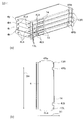
図1(a)は本実施形態に係る画像形成装置の斜視図である。図1(b)は本実施形態に係る画像形成装置の構成図である。
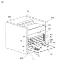
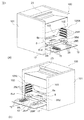
図1に示すように、本実施形態の画像形成装置100は、現像カートリッジ(第2のカートリッジ)4y、4m、4c、4k、ドラムカートリッジ(第1のカートリッジ)8を有している。図3に示すように、現像カートリッジ4y~4kは、ドア10を開いた状態で、画像形成装置本体101の現像カートリッジ着脱部102に対して取り外し可能に装着される。図4に示すように、ドラムカートリッジ8は、ドア10を開いた状態で、現像カートリッジ4y~4kを取り外した後、装置本体101のドラムカートリッジ着脱部104(図5(a)参照)に対して取り外し可能に装着される。
ドラムカートリッジ8は、感光ドラム(感光体)1を有している。感光ドラム1は、帯電器2によりドラム表面を帯電され、露光装置3により画像情報に基づいたレーザー光Lを露光され、静電潜像が形成される。静電潜像は、現像カートリッジ4y~4kによりイエロー、マゼンタ、シアン、ブラックの各色のトナーを用いて各色のトナー像として現像される。現像されたトナー像は、中間転写ユニット5の中間転写ベルト51に1次転写される。1次転写後に感光ドラム1に残った転写残トナーはドラムクリーニング装置6によりクリーニングされる。
一方、給送カセット17に積載されたシートSは、給送ローラ18、レジストローラ対19により、2次転写ローラ32と中間転写ベルト51とのニップ部へ搬送され、中間転写ベルト51に1次転写されたトナー像を2次転写される。トナー像を転写されたシートSは、定着部20でトナー像を定着され、排出ローラ対23により装置本体外へ排出される。2次転写後に中間転写ベルト51に残った転写残トナーはベルトクリーニング装置7によりクリーニングされる。
(現像カートリッジ4y~4kの交換方式)
装置本体101の前面には、開口部103が設けられている。ドア10は、ドア下辺側のヒンジ軸10bを中心に装置本体101に対して回動し、開口部103を開閉可能となっている。ドア10に設けた取手部10aをもってドア10を開くことで、図2に示すように、現像カートリッジ着脱部102が開放される。
図5に示すように、装置本体101の右側フレーム105Rと左側フレーム105Lの内壁面には、4組の水平方向に伸びたガイドレール25R、25Lが対向して設けられている。図6に示すように、現像カートリッジ4y~4kの左側面部と右側面部にはそれぞれ被ガイド部4Ra、4Laが設けられている。被ガイド突起4Ra、4Laがガイドレール25R、25Lを水平方向(矢印X1、X2方向)にスライドすることで、現像カートリッジ4y~4kは現像カートリッジ着脱部102に着脱可能となる。
図5に示すように、ドア10の内側の内面10cには、位置決め押圧部(接触部)26が設けられている。押圧部26は、ドア10を閉じた状態で、現像カートリッジ4y~4kを現像カートリッジ着脱部102に押し込む方向(矢印X2方向)に押圧し、現像カートリッジ4y~4kを装置本体101内に位置決めする。
(ドラムカートリッジ8の交換方式)
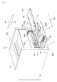
図7に示すように、ドラムカートリッジ8は、上述のごとくドア10を開けて、現像カートリッジ4y~4kを取り外した状態で着脱される。ドラムカートリッジ8は、装置本体101の底面に設けられた左右のガイドレール27R、27Lにより、取り出し方向(X1方向)、もしくは装着方向(X2方向)にガイドされ、ドラムカートリッジ着脱部104に着脱される。
(ドラムカートリッジ着脱ガイド28)
図2、図5、図7、図8に示すように、ドア10の内面10cには、左右にドラムカートリッジ着脱ガイド(着脱経路規制部材)28R、28Lが設けられている。
ドラムカートリッジ着脱ガイド28R、28Lは、現像カートリッジ4y~4kが画像形成装置本体内に位置している際に、取り出し方向において、ドラムカートリッジ着脱ガイド28R、28Lの位置が現像カートリッジ4y~4kの重心位置よりもドア側に設けられている。着脱ガイド28R、28Lは、幅方向(矢印X4方向)に対して、ドラムカートリッジ8の幅以下の距離で離れて設けられている。
着脱ガイド28R、28Lは、ドア10を開いた状態でドラムカートリッジ取り出し方向(X1方向)において、上方に傾斜した斜面28aを有している。なお、図9に示すように、斜面28aは、緩やかな面であれば、曲面であってもよい。また、斜面と曲面から構成されてもよい。着脱ガイド28R、28Lは、図8(a)に示すように左側面方向から見て同形状で、取り出し方向(X1方向)に同じ位置に設けられている。このため、ドラムカートリッジ8は着脱ガイド28R、28Lに同時に接触する。これにより、ドラムカートリッジ8が傾くことを抑制できる。
図8(a)に示すように、着脱ガイド28R、28Lは、ドア10を開いた状態において、現像カートリッジ4y~4kの接点14(図6参照)と接触する接点(接触部)15、押圧部26よりも、装置本体内側に設けられている。現像カートリッジ4y~4kは接点14を介して装置本体から通電可能となっており、電気信号を受けて動作する。接点15、押圧部26は、ドア10から突出している。また、着脱ガイド28R、28Lは、ドア10を左側面方向から見ると、接点15、押圧部26よりも高くなっている(矢印X3方向における高さ)。
ドラムカートリッジ8を装置本体101から取り出す際には、ドラムカートリッジ着脱部104にあるドラムカートリッジ8を引き出していくと、ドラムカートリッジ8の下端が、着脱ガイド28R、28Lの斜面28aに接触する。そして、ドラムカートリッジ8は、斜面28aに沿って、接点15、押圧部26から遠ざかる方向に移動され、ドラムカートリッジ8が接点15、押圧部26に接触しないようになっている。
このように、着脱ガイド28R、28Lは、ドラムカートリッジ8が、接点15、押圧部26と干渉しない経路を通るように規制している。これにより、小型化した画像形成装置100からドラムカートリッジ8を取り外す際に、ドラムカートリッジ8がドア10の接点15、押圧部26に接触することを抑制し、接点15、押圧部26の損傷や破損を抑制できる。
なお、着脱ガイド28R、28Lは、2つに限られるものではなく、1つ、もしくは3個以上あってもよい。また、着脱ガイド28R、28Lの幅(矢印X4方向の幅)は、特に規定しないが、ドラムカートリッジ8を取り出す時に、ドラムカートリッジ8と接触しても破損しない様に一定以上の強度を保つことが可能な幅となっている。
なお、本実施形態では、着脱ガイド28R、28Lは、ドラムカートリッジ8を規制するものとして説明した。しかし、本願発明において、着脱ガイド28R、28Lが規制するものは、ドラムカートリッジに限定されるものではなく、現像カートリッジ4y~4k等の装置本体に着脱可能なカートリッジであってもよい。すなわち、現像カートリッジ4y~4kを装置本体101から取り出し時に、着脱ガイド28R、28Lが現像カートリッジ4y~4k等に当接して、現像カートリッジ4y~4k等が接点15、押圧部26に接触することを抑制する構成であればよい。
図10、図11に示すように、ドラムカートリッジ8は、開口部103に近い側まで伸びた引き出し部材8cに、取っ手8aと、左右の逃げ部8Rd、8Ldを有している。逃げ部8Rd、8Ldは、ドラムカートリッジ8のドア10に近い側の端部よりもへこんだ形状とすることにより設けられる。取っ手8aを開口部103に近い側の面に設けることで、ドラムカートリッジ8を取り出しやすくなっている。逃げ部8Rd、8LdのX4方向の幅は、着脱ガイド28R、28Lの矢印X4方向の幅よりも大きくなっている。また、逃げ部8Rd、8LdのX1方向の幅は、着脱ガイド28R、28Lの矢印X3方向の高さよりも大きくなっている。これにより、ドア10を閉めた時に、着脱ガイド28R、28Lが逃げ部8Rd、8Ldを通ることができ、着脱ガイド28R、28Lとドラムカートリッジ8が干渉しないようになっている。
[第2実施形態]
次に本発明に係る画像形成装置の第2実施形態について図を用いて説明する。上記第1実施形態と説明の重複する部分については、同一の符号を付して説明を省略する。図12(a)は本実施形態に係るドア10の側面図である。図12(b)は本実施形態に係るドア10の平面図である。
図12に示すように、本実施形態の画像形成装置は、上記第1実施形態の画像形成装置のドラムカートリッジ着脱ガイド28R、28Lに変えて、ドラムカートリッジ着脱ガイド30R、30Lを設けたものである。着脱ガイド30R、30Lは、着脱ガイド28R、28Lを引き出し方向(矢印X1方向)に延ばしたものである。ドラムカートリッジ8の着脱時に、ドラムカートリッジ8を取り出す引き出し方向において、着脱ガイド30R、30Lの平面部30bが、それぞれ4つ設けられた接点15、押圧部26のすべてを覆う長さとなっている。
着脱ガイド30R、30Lは、接点15、押圧部26の幅方向(矢印X4方向)外側に設けられているが、内側に設けてもよい。着脱ガイド30R、30Lは、幅方向(矢印X4方向)に対して、ドラムカートリッジ8の幅以下の距離で離れて設けられている。
着脱ガイド30R、30Lは、同形状であり、取り出し方向(X1方向)において、同じ位置に設けられている。このため、ドラムカートリッジ8は着脱ガイド30R、30Lに同時に接触する。これにより、ドラムカートリッジ8が傾くことを抑制できる。
着脱ガイド30R、30Lは、ドア10を開いた状態で、ドラムカートリッジ取り出し方向(X1方向)において、上方に傾斜した斜面30aを有している。着脱ガイド30R、30Lは、接点15、押圧部26よりも矢印X3方向において高くなっている。
ドラムカートリッジ8を装置本体101から取り出す際には、ドラムカートリッジ着脱部104にあるドラムカートリッジ8を引き出していくと、ドラムカートリッジ8の下端が、着脱ガイド30R、30Lの斜面30aに接触する。そして、ドラムカートリッジ8は、斜面30aに沿って上方(ドア10の内面10cから遠ざかる方向)に移動し、平面部30bにガイドされて引き出される。このため、ドラムカートリッジ8が接点15、押圧部26に接触しないようになっている。
これにより、上記第1実施形態と同様に、小型化した画像形成装置100からドラムカートリッジ8を取り外す際に、ドラムカートリッジ8がドア10の接点15、押圧部26に接触することを抑制し、接点15、押圧部26の損傷や破損を抑制できる。
また、平面部30bを設けたことにより、さらに安定してドラムカートリッジ8を着脱することができ、ドラムカートリッジ8が接点15、押圧部26と衝突する可能性をさらに低減することができる。
図13に示すように、ドラムカートリッジ8は、上記第1実施形態の逃げ部8Rd、8Ldから構成を変更している。逃げ部8Rd、8Ldは、ドア10を閉めた時に、着脱ガイド30R、30Lが通ることができるように構成されており、着脱ガイド30R、30Lとドラムカートリッジ8が干渉しないようになっている。
図14に示すように、本実施形態の現像カートリッジ4y~4kは、装置本体に装着した状態において装置本体外側となる面に、左右に逃げ部4Rb、4Lbを有している。ドア10を閉めた時に、着脱ガイド30R、30Lが逃げ部4Rb・4Lbに通過し、着脱ガイド30R、30Lと現像カートリッジ4y~4kが干渉しない様になっている。
[第3実施形態]
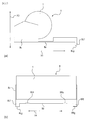
次に本発明に係る画像形成装置の第3実施形態について図を用いて説明する。上記第1もしくは第2実施形態と説明の重複する部分については、同一の符号を付して説明を省略する。図15(a)は、本実施形態に係るドラムカートリッジ8の側面図である。図15(b)は、本実施形態に係るドラムカートリッジ8の正面図である。
(ドラムカートリッジ脚部8f)
図15に示す様に、本実施形態の画像形成装置は、ドラムカートリッジ着脱ガイド28R・28Lを設ける箇所をドア内面10cからドラムカートリッジ下面8eに変更し、ドラムカートリッジ脚部8Rf・8Lfとしている。ドラムカートリッジ脚部8Rf・8Lfは、ドラムカートリッジ8が装置本体101に装着されている時、ドア10に近い側に設置されている。なお、本実施形態においては、図15(a)において、脚部8Rf・8Lfがドラムカートリッジ8の取り出し方向(X1方向)の端部と一致する箇所に設けられているが、ドラムカートリッジ8を装置本体101から引き出す時に、ドラムカートリッジ8の傾きを防止可能な位置であれば、脚部8Rf・8Lfは別の位置に設けられていてもよい。
ドラムカートリッジ脚部8Rf・8LfのX3方向の高さは、ドラムカートリッジ8が傾いてドラムカートリッジ脚部8Rf・8Lfで支持する際に、ドア上の接点15及び位置決め押圧部26と接触しない様に、接点15及び押圧部26と比較して大きくなっている。
ドラムカートリッジ脚部8Rf・8Lfを装置本体101に装着する時、ドア内面10cと接する脚部下面8Rg・8Lgは、ドラムカートリッジ8の底面8eに対して平行な平面となっている。なお、ドラムカートリッジ8を装置本体101から引き出す際に、ドラムカートリッジ8を傾けることなく支えることが可能であれば、脚部下面8Rg・8Lgは、底面8eと平行な平面でなくてもよく、例えば曲面であったとしてもよい。
図15(b)に示す様に、ドラムカートリッジ脚部8Rf・8Lf間の距離は、図16(b)で示すドア10のヒンジ軸10bのX4方向の幅より大きくなっている。なお、本実施例においては脚部8Rf・8Lfは2つとしているが、装置本体101からドラムカートリッジ8を取り出す際、ドア10のヒンジ軸10bと接しない構造であれば、1つ、もしくは3つ以上であってもよい。また、ドアのヒンジ軸は2つ以上であってもよい。
ドラムカートリッジ脚部8Rfは、ドラムカートリッジ8を正面方向から見ると、位置決め押圧部26の位置より右側に設けられ、右端とドラムカートリッジ8の右端が一致するように設けられている。また、脚部8RfのX4方向の幅は特に規定しないが、ドラムカートリッジ8が傾いた際に支持可能な強度を有するように、一定以上の強度を保つことが可能な幅となっている。
なお、本実施形態においては脚部8Rfの右端が、ドラムカートリッジ8の右端と一致しているが、強度を保つことが可能であり、ドラムカートリッジ8を傾けることなく支持可能であれば、一致していなくてもよい。また、本実施例においては、ドラムカートリッジ8を装置本体101に装着した時、脚部8Rfは押圧部26の位置より右側に配置されているが、ドラムカートリッジ8を傾けることなく支持可能であれば、押圧部26より左側に配置されてもよい。
ドラムカートリッジ脚部8Lfは、ドラムカートリッジ8を正面方向から見ると、接点15の位置より左側に設けられ、左端とドラムカートリッジ8の左端が一致するように設けられている。また、脚部8LfのX4方向の幅は特に規定しないが、ドラムカートリッジ8が傾いた際に支持可能な強度を有するように、一定以上の強度を保つことが可能な幅となっている。
なお、本実施形態においては脚部8Lfの左端が、ドラムカートリッジ8の左端と一致しているが、強度を保つことが可能であり、ドラムカートリッジ8を傾けることなく支持可能であれば、一致していなくてもよい。また、本実施例においては、ドラムカートリッジ8を装置本体101に装着した時、脚部8Lfは接点15の位置より左側に配置されているが、ドラムカートリッジ8を傾けることなく支持可能であれば、接点15より右側に配置されてもよい。
ドラムカートリッジ8は、装置本体101から取り出す前及び取り出した直後はドラムカートリッジの下面8eが装置本体101に接触していて支持されているが、ある程度取り出すと、ドラムカートリッジの重心が画像形成装置本体に対して移動し、自重によりドラムカートリッジ8が傾くため、下面8eの一部が装置本体101と、ドラムカートリッジ脚部下面8Rg・8Lgがドア内面10cと接触し、支持されるようになる。この時、上述したように、ドラムカートリッジ脚部8Rf・8LfのX3方向の高さが接点15及び位置決め押圧部26と比較して大きいため、ドラムカートリッジ8を本体101から取り出す際に、ドラムカートリッジ8本体と接点15及び位置決め押圧部26との接触を回避することが出来る。
なお、図15(a)に示すように、本実施形態においては、ドラムカートリッジ脚部8Rf・8Lfは下面8eの取り出し方向(X1方向)の端部に一対設けられているが、図17(a)で示すように、さらに装着方向(X2方向)の端部に一対設けてもよい。この構成により、ドラムカートリッジ8を装置本体101から取り出す際に、ある程度以上取り出すと、取り出し方向(X1方向)端部の脚部8Rf・8Lfはドア面10cから離れるためドラムカートリッジ8を支持出来なくなるが、装着方向(X2方向)の端部の脚部8Rf・8Lfが支持出来るため、よりドラムカートリッジ8と接点15及び押圧部26との接触をより回避することが出来る。
また、ドラムカートリッジ脚部8Rf・8LfのX1方向の幅は、ドラムカートリッジ8を傾けることなく支持可能であれば特に規定しないが、図17(b)で示す様に、取り出し方向(X1方向)の端部から装着方向(X2方向)の端部まで延長されることで、上記と同様に、よりドラムカートリッジ8と接点15及び押圧部26との接触を回避することが出来る。
なお、本実施形態で示したドラムカートリッジ脚部8Rf・8Lfが規定するのは、本実施形態の様なドラムカートリッジ8に限られるものではなく、装置本体101に着脱可能なカートリッジであれば、例えば現像カートリッジ等の他のカートリッジであったとしてもよい。
(ドアの構成例)
本実施形態では、ドア10とドア10bの一部形状を変更している。
図16に示す様に、ドア10のヒンジ軸10bはX4方向にドア10の中央に配置されていて、装置本体101に対してドア10が開閉可能となっている。なお、本実施形態においては、ヒンジ軸10bは1つとしているが、ドラムカートリッジ脚部8Rf・8Lfと干渉しない構造であれば、中央以外の位置に配置されてもよく、また2つ以上であってもよい。
[第4実施形態]
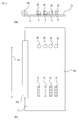
次に本発明に係る画像形成装置の第4実施形態について図を用いて説明する。上記第1から第3実施形態と説明の重複する部分については、同一の符号を付して説明を省略する。図18(a)は本実施形態に係る画像形成装置の斜視図である。図1(b)本実施形態に係る画像形成装置の構成図である。
図18に示すように、本実施形態の画像形成装置100は、現像器とドラムを有したオールインワンカートリッジ(プロセスカートリッジ)9を有している。図20に示すように、オールインワンカートリッジ9は、ドア10を開いた状態で、画像形成装置本体101のオールインワンカートリッジ着脱部106に対して取り外し可能に装着される。
オールインワンカートリッジ9は、感光ドラム1を有している。感光ドラム1は、帯電器2によりドラム表面を帯電され、露光装置3により画像情報に基づいたレーザー光Lを露光され、静電潜像が形成される。静電潜像は、現像ローラ4aにより、ブラックのトナーを用いてトナー像として現像される。
一方、給送カセット17に積載されたシートSは、給送ローラ18、レジストローラ対19により、転写ローラ32と感光ドラム1とのニップ部へ搬送され、感光ドラム1に転写されたトナー像を転写される。トナー像を転写されたシートSは、定着部20でトナー像を定着され、排出ローラ対23により装置本体外へ排出される。また、感光ドラム1に残った転写残トナーはドラムクリーニング装置6によりクリーニングされる。
(オールインワンカートリッジ9の交換方式)
ドア10に設けた取手部10aをもってドア10を開くことで、開口部103が開き、図19に示すように、オールインワンカートリッジ着脱部106が開放される。
図20に示すように、オールインワンカートリッジ9は、上述のごとくドア10を開けた状態で、着脱される。オールインワンカートリッジ9は、装置本体101の底面に設けられた左右のガイドレール27R、27Lにより、取り出し方向(X1方向)、もしくは装着方向(X2方向)にガイドされ、オールインワンカートリッジ着脱部106に着脱される。
図21に示すように、ドア10の内面10cには、位置決め押圧部(接触部)26が設けられている。押圧部26は、ドア10を閉じた状態で、オールインワンカートリッジ9をオールインワンカートリッジ着脱部106に押し込む方向(矢印X2方向)に押圧し、オールインワンカートリッジ9を装置本体101内に位置決めする。
(オールインワンカートリッジ着脱ガイド28)
図19、図21、図22に示すように、ドア10の内面10cには、左右にオールインワンカートリッジ着脱ガイド(着脱経路規制部材)28R、28Lが設けられている。オールインワンカートリッジ着脱ガイド28R、28Lは、上記第1実施形態からガイドする対象を、ドラムカートリッジ8からオールインワンカートリッジ9に変更しているが、構成はドラムカートリッジ着脱ガイド28R、28Lと同様である。なお、本実施形態における効果の対象に関しても、ドラムカートリッジ8からオールインワンカートリッジ9に変更しているが、実施形態1と効果の内容は同様である。
図23に示すように、オールインワンカートリッジ9は、開口部103に近い側まで伸びた引き出し部材9aに、取っ手9bと、左右の逃げ部9Rd、9Ldを有している。取っ手9bを開口部103に近い側の面に設けることで、オールインワンカートリッジ9を取り出しやすくなっている。逃げ部9Rd、9LdのX4方向の幅は、着脱ガイド28R、28Lの矢印X4方向の幅よりも大きくなっている。また、逃げ部9Rd、9LdのX1方向の幅は、着脱ガイド28R、28Lの矢印X3方向の高さよりも大きくなっている。これにより、ドア10を閉めた時に、着脱ガイド28R、28Lが逃げ部9Rd、9Ldを通ることができ、着脱ガイド28R、28Lとオールインワンカートリッジ9が干渉しないようになっている。
[第5実施形態]
次に本発明に係る画像形成装置の第5実施形態について図を用いて説明する。上記第1から第4実施形態と説明の重複する部分については、同一の符号を付して説明を省略する。
図24に示すように、本実施形態の画像形成装置は、上記第4実施形態の画像形成装置のオールインワンカートリッジ着脱ガイド28R、28Lに変えて、オールインワンカートリッジ着脱ガイド30R、30Lを設けたものである。また、オールインワンカートリッジ着脱ガイド30R、30Lは、上記第2実施形態からガイドする対象を、ドラムカートリッジ8からオールインワンカートリッジ9に変更しているが、構成はドラムカートリッジ着脱ガイド28R、28Lと同様である。なお、本実施例における効果の対象に関しても、ドラムカートリッジ8からオールインワンカートリッジ9に変更しているが、実施形態2と効果の内容は同様である。
図25に示すように、オールインワンカートリッジ9は、上記第4実施形態の逃げ部9Rd、9Ldから構成を変更している。逃げ部9Rd、9Ldは、ドア10を閉めた時に、着脱ガイド30R、30Lが通ることができるように構成されており、着脱ガイド30R、30Lとオールインワンカートリッジ9が干渉しないようになっている。
[第6実施形態]
次に本発明に係る画像形成装置の第5実施形態について図を用いて説明する。上記第1から第5実施形態と説明の重複する部分については、同一の符号を付して説明を省略する。図26(a)は、本実施形態に係るオールインワンカートリッジ9の側面図である。図26(b)は、本実施形態に係るオールインワンカートリッジ9の正面図である。
(オールインワンカートリッジ脚部9f)
図26に示す様に、本実施形態の画像形成装置は、オールインワンカートリッジ着脱ガイド30R、30Lを設ける箇所をドア内面10cからオールインワンカートリッジ下面9eに変更し、オールインワンカートリッジ脚部9Rf、9Lfとしている。また、上記第3実施形態からガイドする対象を、ドラムカートリッジ8からオールインワンカートリッジ9に変更しているが、構成はドラムカートリッジ脚部8Rf、8Lfと同様である。なお、本実施例における効果の対象に関しても、ドラムカートリッジ8からオールインワンカートリッジ9に変更しているが、実施形態3と効果の内容は同様である。
以上実施形態1から6の構成により、画像形成装置の小型化に伴って、装置本体からカートリッジを取り出す経路が狭まったとしても、ユーザーはドア上の押圧部及び接点を破損させることなく、容易にカートリッジを装置本体から取り出すことが出来る。
本発明に係る画像形成装置の第1実施形態について、図を用いて説明する。
(画像形成装置100の概略説明)
図1(a)は本実施形態に係る画像形成装置の斜視図である。図1(b)は本実施形態に係る画像形成装置の構成図である。
図1に示すように、本実施形態の画像形成装置100は、現像カートリッジ(第2のカートリッジ)4y、4m、4c、4k、ドラムカートリッジ(第1のカートリッジ)8を有している。図3に示すように、現像カートリッジ4y~4kは、ドア10を開いた状態で、画像形成装置本体101の現像カートリッジ着脱部102に対して取り外し可能に装着される。図4に示すように、ドラムカートリッジ8は、ドア10を開いた状態で、現像カートリッジ4y~4kを取り外した後、装置本体101のドラムカートリッジ着脱部104(図5(a)参照)に対して取り外し可能に装着される。
ドラムカートリッジ8は、感光ドラム(感光体)1を有している。感光ドラム1は、帯電器2によりドラム表面を帯電され、露光装置3により画像情報に基づいたレーザー光Lを露光され、静電潜像が形成される。静電潜像は、現像カートリッジ4y~4kによりイエロー、マゼンタ、シアン、ブラックの各色のトナーを用いて各色のトナー像として現像される。現像されたトナー像は、中間転写ユニット5の中間転写ベルト51に1次転写される。1次転写後に感光ドラム1に残った転写残トナーはドラムクリーニング装置6によりクリーニングされる。
一方、給送カセット17に積載されたシートSは、給送ローラ18、レジストローラ対19により、2次転写ローラ32と中間転写ベルト51とのニップ部へ搬送され、中間転写ベルト51に1次転写されたトナー像を2次転写される。トナー像を転写されたシートSは、定着部20でトナー像を定着され、排出ローラ対23により装置本体外へ排出される。2次転写後に中間転写ベルト51に残った転写残トナーはベルトクリーニング装置7によりクリーニングされる。
(現像カートリッジ4y~4kの交換方式)
装置本体101の前面には、開口部103が設けられている。ドア10は、ドア下辺側のヒンジ軸10bを中心に装置本体101に対して回動し、開口部103を開閉可能となっている。ドア10に設けた取手部10aをもってドア10を開くことで、図2に示すように、現像カートリッジ着脱部102が開放される。
図5に示すように、装置本体101の右側フレーム105Rと左側フレーム105Lの内壁面には、4組の水平方向に伸びたガイドレール25R、25Lが対向して設けられている。図6に示すように、現像カートリッジ4y~4kの左側面部と右側面部にはそれぞれ被ガイド部4Ra、4Laが設けられている。被ガイド突起4Ra、4Laがガイドレール25R、25Lを水平方向(矢印X1、X2方向)にスライドすることで、現像カートリッジ4y~4kは現像カートリッジ着脱部102に着脱可能となる。
図5に示すように、ドア10の内側の内面10cには、位置決め押圧部(接触部)26が設けられている。押圧部26は、ドア10を閉じた状態で、現像カートリッジ4y~4kを現像カートリッジ着脱部102に押し込む方向(矢印X2方向)に押圧し、現像カートリッジ4y~4kを装置本体101内に位置決めする。
(ドラムカートリッジ8の交換方式)
図7に示すように、ドラムカートリッジ8は、上述のごとくドア10を開けて、現像カートリッジ4y~4kを取り外した状態で着脱される。ドラムカートリッジ8は、装置本体101の底面に設けられた左右のガイドレール27R、27Lにより、取り出し方向(X1方向)、もしくは装着方向(X2方向)にガイドされ、ドラムカートリッジ着脱部104に着脱される。
(ドラムカートリッジ着脱ガイド28)
図2、図5、図7、図8に示すように、ドア10の内面10cには、左右にドラムカートリッジ着脱ガイド(着脱経路規制部材)28R、28Lが設けられている。
ドラムカートリッジ着脱ガイド28R、28Lは、現像カートリッジ4y~4kが画像形成装置本体内に位置している際に、取り出し方向において、ドラムカートリッジ着脱ガイド28R、28Lの位置が現像カートリッジ4y~4kの重心位置よりもドア側に設けられている。着脱ガイド28R、28Lは、幅方向(矢印X4方向)に対して、ドラムカートリッジ8の幅以下の距離で離れて設けられている。
着脱ガイド28R、28Lは、ドア10を開いた状態でドラムカートリッジ取り出し方向(X1方向)において、上方に傾斜した斜面28aを有している。なお、図9に示すように、斜面28aは、緩やかな面であれば、曲面であってもよい。また、斜面と曲面から構成されてもよい。着脱ガイド28R、28Lは、図8(a)に示すように左側面方向から見て同形状で、取り出し方向(X1方向)に同じ位置に設けられている。このため、ドラムカートリッジ8は着脱ガイド28R、28Lに同時に接触する。これにより、ドラムカートリッジ8が傾くことを抑制できる。
図8(a)に示すように、着脱ガイド28R、28Lは、ドア10を開いた状態において、現像カートリッジ4y~4kの接点14(図6参照)と接触する接点(接触部)15、押圧部26よりも、装置本体内側に設けられている。現像カートリッジ4y~4kは接点14を介して装置本体から通電可能となっており、電気信号を受けて動作する。接点15、押圧部26は、ドア10から突出している。また、着脱ガイド28R、28Lは、ドア10を左側面方向から見ると、接点15、押圧部26よりも高くなっている(矢印X3方向における高さ)。
ドラムカートリッジ8を装置本体101から取り出す際には、ドラムカートリッジ着脱部104にあるドラムカートリッジ8を引き出していくと、ドラムカートリッジ8の下端が、着脱ガイド28R、28Lの斜面28aに接触する。そして、ドラムカートリッジ8は、斜面28aに沿って、接点15、押圧部26から遠ざかる方向に移動され、ドラムカートリッジ8が接点15、押圧部26に接触しないようになっている。
このように、着脱ガイド28R、28Lは、ドラムカートリッジ8が、接点15、押圧部26と干渉しない経路を通るように規制している。これにより、小型化した画像形成装置100からドラムカートリッジ8を取り外す際に、ドラムカートリッジ8がドア10の接点15、押圧部26に接触することを抑制し、接点15、押圧部26の損傷や破損を抑制できる。
なお、着脱ガイド28R、28Lは、2つに限られるものではなく、1つ、もしくは3個以上あってもよい。また、着脱ガイド28R、28Lの幅(矢印X4方向の幅)は、特に規定しないが、ドラムカートリッジ8を取り出す時に、ドラムカートリッジ8と接触しても破損しない様に一定以上の強度を保つことが可能な幅となっている。
なお、本実施形態では、着脱ガイド28R、28Lは、ドラムカートリッジ8を規制するものとして説明した。しかし、本願発明において、着脱ガイド28R、28Lが規制するものは、ドラムカートリッジに限定されるものではなく、現像カートリッジ4y~4k等の装置本体に着脱可能なカートリッジであってもよい。すなわち、現像カートリッジ4y~4kを装置本体101から取り出し時に、着脱ガイド28R、28Lが現像カートリッジ4y~4k等に当接して、現像カートリッジ4y~4k等が接点15、押圧部26に接触することを抑制する構成であればよい。
図10、図11に示すように、ドラムカートリッジ8は、開口部103に近い側まで伸びた引き出し部材8cに、取っ手8aと、左右の逃げ部8Rd、8Ldを有している。逃げ部8Rd、8Ldは、ドラムカートリッジ8のドア10に近い側の端部よりもへこんだ形状とすることにより設けられる。取っ手8aを開口部103に近い側の面に設けることで、ドラムカートリッジ8を取り出しやすくなっている。逃げ部8Rd、8LdのX4方向の幅は、着脱ガイド28R、28Lの矢印X4方向の幅よりも大きくなっている。また、逃げ部8Rd、8LdのX1方向の幅は、着脱ガイド28R、28Lの矢印X3方向の高さよりも大きくなっている。これにより、ドア10を閉めた時に、着脱ガイド28R、28Lが逃げ部8Rd、8Ldを通ることができ、着脱ガイド28R、28Lとドラムカートリッジ8が干渉しないようになっている。
[第2実施形態]
次に本発明に係る画像形成装置の第2実施形態について図を用いて説明する。上記第1実施形態と説明の重複する部分については、同一の符号を付して説明を省略する。図12(a)は本実施形態に係るドア10の側面図である。図12(b)は本実施形態に係るドア10の平面図である。
図12に示すように、本実施形態の画像形成装置は、上記第1実施形態の画像形成装置のドラムカートリッジ着脱ガイド28R、28Lに変えて、ドラムカートリッジ着脱ガイド30R、30Lを設けたものである。着脱ガイド30R、30Lは、着脱ガイド28R、28Lを引き出し方向(矢印X1方向)に延ばしたものである。ドラムカートリッジ8の着脱時に、ドラムカートリッジ8を取り出す引き出し方向において、着脱ガイド30R、30Lの平面部30bが、それぞれ4つ設けられた接点15、押圧部26のすべてを覆う長さとなっている。
着脱ガイド30R、30Lは、接点15、押圧部26の幅方向(矢印X4方向)外側に設けられているが、内側に設けてもよい。着脱ガイド30R、30Lは、幅方向(矢印X4方向)に対して、ドラムカートリッジ8の幅以下の距離で離れて設けられている。
着脱ガイド30R、30Lは、同形状であり、取り出し方向(X1方向)において、同じ位置に設けられている。このため、ドラムカートリッジ8は着脱ガイド30R、30Lに同時に接触する。これにより、ドラムカートリッジ8が傾くことを抑制できる。
着脱ガイド30R、30Lは、ドア10を開いた状態で、ドラムカートリッジ取り出し方向(X1方向)において、上方に傾斜した斜面30aを有している。着脱ガイド30R、30Lは、接点15、押圧部26よりも矢印X3方向において高くなっている。
ドラムカートリッジ8を装置本体101から取り出す際には、ドラムカートリッジ着脱部104にあるドラムカートリッジ8を引き出していくと、ドラムカートリッジ8の下端が、着脱ガイド30R、30Lの斜面30aに接触する。そして、ドラムカートリッジ8は、斜面30aに沿って上方(ドア10の内面10cから遠ざかる方向)に移動し、平面部30bにガイドされて引き出される。このため、ドラムカートリッジ8が接点15、押圧部26に接触しないようになっている。
これにより、上記第1実施形態と同様に、小型化した画像形成装置100からドラムカートリッジ8を取り外す際に、ドラムカートリッジ8がドア10の接点15、押圧部26に接触することを抑制し、接点15、押圧部26の損傷や破損を抑制できる。
また、平面部30bを設けたことにより、さらに安定してドラムカートリッジ8を着脱することができ、ドラムカートリッジ8が接点15、押圧部26と衝突する可能性をさらに低減することができる。
図13に示すように、ドラムカートリッジ8は、上記第1実施形態の逃げ部8Rd、8Ldから構成を変更している。逃げ部8Rd、8Ldは、ドア10を閉めた時に、着脱ガイド30R、30Lが通ることができるように構成されており、着脱ガイド30R、30Lとドラムカートリッジ8が干渉しないようになっている。
図14に示すように、本実施形態の現像カートリッジ4y~4kは、装置本体に装着した状態において装置本体外側となる面に、左右に逃げ部4Rb、4Lbを有している。ドア10を閉めた時に、着脱ガイド30R、30Lが逃げ部4Rb・4Lbに通過し、着脱ガイド30R、30Lと現像カートリッジ4y~4kが干渉しない様になっている。
[第3実施形態]
次に本発明に係る画像形成装置の第3実施形態について図を用いて説明する。上記第1もしくは第2実施形態と説明の重複する部分については、同一の符号を付して説明を省略する。図15(a)は、本実施形態に係るドラムカートリッジ8の側面図である。図15(b)は、本実施形態に係るドラムカートリッジ8の正面図である。
(ドラムカートリッジ脚部8f)
図15に示す様に、本実施形態の画像形成装置は、ドラムカートリッジ着脱ガイド28R・28Lを設ける箇所をドア内面10cからドラムカートリッジ下面8eに変更し、ドラムカートリッジ脚部8Rf・8Lfとしている。ドラムカートリッジ脚部8Rf・8Lfは、ドラムカートリッジ8が装置本体101に装着されている時、ドア10に近い側に設置されている。なお、本実施形態においては、図15(a)において、脚部8Rf・8Lfがドラムカートリッジ8の取り出し方向(X1方向)の端部と一致する箇所に設けられているが、ドラムカートリッジ8を装置本体101から引き出す時に、ドラムカートリッジ8の傾きを防止可能な位置であれば、脚部8Rf・8Lfは別の位置に設けられていてもよい。
ドラムカートリッジ脚部8Rf・8LfのX3方向の高さは、ドラムカートリッジ8が傾いてドラムカートリッジ脚部8Rf・8Lfで支持する際に、ドア上の接点15及び位置決め押圧部26と接触しない様に、接点15及び押圧部26と比較して大きくなっている。
ドラムカートリッジ脚部8Rf・8Lfを装置本体101に装着する時、ドア内面10cと接する脚部下面8Rg・8Lgは、ドラムカートリッジ8の底面8eに対して平行な平面となっている。なお、ドラムカートリッジ8を装置本体101から引き出す際に、ドラムカートリッジ8を傾けることなく支えることが可能であれば、脚部下面8Rg・8Lgは、底面8eと平行な平面でなくてもよく、例えば曲面であったとしてもよい。
図15(b)に示す様に、ドラムカートリッジ脚部8Rf・8Lf間の距離は、図16(b)で示すドア10のヒンジ軸10bのX4方向の幅より大きくなっている。なお、本実施例においては脚部8Rf・8Lfは2つとしているが、装置本体101からドラムカートリッジ8を取り出す際、ドア10のヒンジ軸10bと接しない構造であれば、1つ、もしくは3つ以上であってもよい。また、ドアのヒンジ軸は2つ以上であってもよい。
ドラムカートリッジ脚部8Rfは、ドラムカートリッジ8を正面方向から見ると、位置決め押圧部26の位置より右側に設けられ、右端とドラムカートリッジ8の右端が一致するように設けられている。また、脚部8RfのX4方向の幅は特に規定しないが、ドラムカートリッジ8が傾いた際に支持可能な強度を有するように、一定以上の強度を保つことが可能な幅となっている。
なお、本実施形態においては脚部8Rfの右端が、ドラムカートリッジ8の右端と一致しているが、強度を保つことが可能であり、ドラムカートリッジ8を傾けることなく支持可能であれば、一致していなくてもよい。また、本実施例においては、ドラムカートリッジ8を装置本体101に装着した時、脚部8Rfは押圧部26の位置より右側に配置されているが、ドラムカートリッジ8を傾けることなく支持可能であれば、押圧部26より左側に配置されてもよい。
ドラムカートリッジ脚部8Lfは、ドラムカートリッジ8を正面方向から見ると、接点15の位置より左側に設けられ、左端とドラムカートリッジ8の左端が一致するように設けられている。また、脚部8LfのX4方向の幅は特に規定しないが、ドラムカートリッジ8が傾いた際に支持可能な強度を有するように、一定以上の強度を保つことが可能な幅となっている。
なお、本実施形態においては脚部8Lfの左端が、ドラムカートリッジ8の左端と一致しているが、強度を保つことが可能であり、ドラムカートリッジ8を傾けることなく支持可能であれば、一致していなくてもよい。また、本実施例においては、ドラムカートリッジ8を装置本体101に装着した時、脚部8Lfは接点15の位置より左側に配置されているが、ドラムカートリッジ8を傾けることなく支持可能であれば、接点15より右側に配置されてもよい。
ドラムカートリッジ8は、装置本体101から取り出す前及び取り出した直後はドラムカートリッジの下面8eが装置本体101に接触していて支持されているが、ある程度取り出すと、ドラムカートリッジの重心が画像形成装置本体に対して移動し、自重によりドラムカートリッジ8が傾くため、下面8eの一部が装置本体101と、ドラムカートリッジ脚部下面8Rg・8Lgがドア内面10cと接触し、支持されるようになる。この時、上述したように、ドラムカートリッジ脚部8Rf・8LfのX3方向の高さが接点15及び位置決め押圧部26と比較して大きいため、ドラムカートリッジ8を本体101から取り出す際に、ドラムカートリッジ8本体と接点15及び位置決め押圧部26との接触を回避することが出来る。
なお、図15(a)に示すように、本実施形態においては、ドラムカートリッジ脚部8Rf・8Lfは下面8eの取り出し方向(X1方向)の端部に一対設けられているが、図17(a)で示すように、さらに装着方向(X2方向)の端部に一対設けてもよい。この構成により、ドラムカートリッジ8を装置本体101から取り出す際に、ある程度以上取り出すと、取り出し方向(X1方向)端部の脚部8Rf・8Lfはドア面10cから離れるためドラムカートリッジ8を支持出来なくなるが、装着方向(X2方向)の端部の脚部8Rf・8Lfが支持出来るため、よりドラムカートリッジ8と接点15及び押圧部26との接触をより回避することが出来る。
また、ドラムカートリッジ脚部8Rf・8LfのX1方向の幅は、ドラムカートリッジ8を傾けることなく支持可能であれば特に規定しないが、図17(b)で示す様に、取り出し方向(X1方向)の端部から装着方向(X2方向)の端部まで延長されることで、上記と同様に、よりドラムカートリッジ8と接点15及び押圧部26との接触を回避することが出来る。
なお、本実施形態で示したドラムカートリッジ脚部8Rf・8Lfが規定するのは、本実施形態の様なドラムカートリッジ8に限られるものではなく、装置本体101に着脱可能なカートリッジであれば、例えば現像カートリッジ等の他のカートリッジであったとしてもよい。
(ドアの構成例)
本実施形態では、ドア10とドア10bの一部形状を変更している。
図16に示す様に、ドア10のヒンジ軸10bはX4方向にドア10の中央に配置されていて、装置本体101に対してドア10が開閉可能となっている。なお、本実施形態においては、ヒンジ軸10bは1つとしているが、ドラムカートリッジ脚部8Rf・8Lfと干渉しない構造であれば、中央以外の位置に配置されてもよく、また2つ以上であってもよい。
[第4実施形態]
次に本発明に係る画像形成装置の第4実施形態について図を用いて説明する。上記第1から第3実施形態と説明の重複する部分については、同一の符号を付して説明を省略する。図18(a)は本実施形態に係る画像形成装置の斜視図である。図1(b)本実施形態に係る画像形成装置の構成図である。
図18に示すように、本実施形態の画像形成装置100は、現像器とドラムを有したオールインワンカートリッジ(プロセスカートリッジ)9を有している。図20に示すように、オールインワンカートリッジ9は、ドア10を開いた状態で、画像形成装置本体101のオールインワンカートリッジ着脱部106に対して取り外し可能に装着される。
オールインワンカートリッジ9は、感光ドラム1を有している。感光ドラム1は、帯電器2によりドラム表面を帯電され、露光装置3により画像情報に基づいたレーザー光Lを露光され、静電潜像が形成される。静電潜像は、現像ローラ4aにより、ブラックのトナーを用いてトナー像として現像される。
一方、給送カセット17に積載されたシートSは、給送ローラ18、レジストローラ対19により、転写ローラ32と感光ドラム1とのニップ部へ搬送され、感光ドラム1に転写されたトナー像を転写される。トナー像を転写されたシートSは、定着部20でトナー像を定着され、排出ローラ対23により装置本体外へ排出される。また、感光ドラム1に残った転写残トナーはドラムクリーニング装置6によりクリーニングされる。
(オールインワンカートリッジ9の交換方式)
ドア10に設けた取手部10aをもってドア10を開くことで、開口部103が開き、図19に示すように、オールインワンカートリッジ着脱部106が開放される。
図20に示すように、オールインワンカートリッジ9は、上述のごとくドア10を開けた状態で、着脱される。オールインワンカートリッジ9は、装置本体101の底面に設けられた左右のガイドレール27R、27Lにより、取り出し方向(X1方向)、もしくは装着方向(X2方向)にガイドされ、オールインワンカートリッジ着脱部106に着脱される。
図21に示すように、ドア10の内面10cには、位置決め押圧部(接触部)26が設けられている。押圧部26は、ドア10を閉じた状態で、オールインワンカートリッジ9をオールインワンカートリッジ着脱部106に押し込む方向(矢印X2方向)に押圧し、オールインワンカートリッジ9を装置本体101内に位置決めする。
(オールインワンカートリッジ着脱ガイド28)
図19、図21、図22に示すように、ドア10の内面10cには、左右にオールインワンカートリッジ着脱ガイド(着脱経路規制部材)28R、28Lが設けられている。オールインワンカートリッジ着脱ガイド28R、28Lは、上記第1実施形態からガイドする対象を、ドラムカートリッジ8からオールインワンカートリッジ9に変更しているが、構成はドラムカートリッジ着脱ガイド28R、28Lと同様である。なお、本実施形態における効果の対象に関しても、ドラムカートリッジ8からオールインワンカートリッジ9に変更しているが、実施形態1と効果の内容は同様である。
図23に示すように、オールインワンカートリッジ9は、開口部103に近い側まで伸びた引き出し部材9aに、取っ手9bと、左右の逃げ部9Rd、9Ldを有している。取っ手9bを開口部103に近い側の面に設けることで、オールインワンカートリッジ9を取り出しやすくなっている。逃げ部9Rd、9LdのX4方向の幅は、着脱ガイド28R、28Lの矢印X4方向の幅よりも大きくなっている。また、逃げ部9Rd、9LdのX1方向の幅は、着脱ガイド28R、28Lの矢印X3方向の高さよりも大きくなっている。これにより、ドア10を閉めた時に、着脱ガイド28R、28Lが逃げ部9Rd、9Ldを通ることができ、着脱ガイド28R、28Lとオールインワンカートリッジ9が干渉しないようになっている。
[第5実施形態]
次に本発明に係る画像形成装置の第5実施形態について図を用いて説明する。上記第1から第4実施形態と説明の重複する部分については、同一の符号を付して説明を省略する。
図24に示すように、本実施形態の画像形成装置は、上記第4実施形態の画像形成装置のオールインワンカートリッジ着脱ガイド28R、28Lに変えて、オールインワンカートリッジ着脱ガイド30R、30Lを設けたものである。また、オールインワンカートリッジ着脱ガイド30R、30Lは、上記第2実施形態からガイドする対象を、ドラムカートリッジ8からオールインワンカートリッジ9に変更しているが、構成はドラムカートリッジ着脱ガイド28R、28Lと同様である。なお、本実施例における効果の対象に関しても、ドラムカートリッジ8からオールインワンカートリッジ9に変更しているが、実施形態2と効果の内容は同様である。
図25に示すように、オールインワンカートリッジ9は、上記第4実施形態の逃げ部9Rd、9Ldから構成を変更している。逃げ部9Rd、9Ldは、ドア10を閉めた時に、着脱ガイド30R、30Lが通ることができるように構成されており、着脱ガイド30R、30Lとオールインワンカートリッジ9が干渉しないようになっている。
[第6実施形態]
次に本発明に係る画像形成装置の第5実施形態について図を用いて説明する。上記第1から第5実施形態と説明の重複する部分については、同一の符号を付して説明を省略する。図26(a)は、本実施形態に係るオールインワンカートリッジ9の側面図である。図26(b)は、本実施形態に係るオールインワンカートリッジ9の正面図である。
(オールインワンカートリッジ脚部9f)
図26に示す様に、本実施形態の画像形成装置は、オールインワンカートリッジ着脱ガイド30R、30Lを設ける箇所をドア内面10cからオールインワンカートリッジ下面9eに変更し、オールインワンカートリッジ脚部9Rf、9Lfとしている。また、上記第3実施形態からガイドする対象を、ドラムカートリッジ8からオールインワンカートリッジ9に変更しているが、構成はドラムカートリッジ脚部8Rf、8Lfと同様である。なお、本実施例における効果の対象に関しても、ドラムカートリッジ8からオールインワンカートリッジ9に変更しているが、実施形態3と効果の内容は同様である。
以上実施形態1から6の構成により、画像形成装置の小型化に伴って、装置本体からカートリッジを取り出す経路が狭まったとしても、ユーザーはドア上の押圧部及び接点を破損させることなく、容易にカートリッジを装置本体から取り出すことが出来る。
以上のように、本発明によれば、小型化した画像形成装置からカートリッジを取り外す際に、カートリッジがドアの位置決め押圧部に接触することを抑制し、位置決め押圧部の損傷や破損を抑制できる画像形成装置が提供される。
Claims (29)
- 画像形成装置は以下を備える:
画像形成装置本体に設けられた開口部に対して開閉可能なドア;
前記ドアを開いた状態で、前記画像形成装置本体に着脱可能な第1のカートリッジ;
前記第1のカートリッジの上方に着脱可能な第2のカートリッジ;
前記ドアに設けられ、前記ドアを閉じた状態で、前記第2のカートリッジと接触する接触部;
前記ドアに設けられ、前記第1のカートリッジを前記画像形成装置から取り外す際に、前記第1のカートリッジに当接して、前記第1のカートリッジを前記接触部と干渉しない経路を通る様に規制する着脱経路規制部材。 - 前記着脱経路規制部材は、前記第1のカートリッジを前記接触部と干渉しない方向にガイドする斜面を有することを特徴とする請求項1に記載の画像形成装置。
- 前記接触部は、前記ドアから突出しており、
前記着脱経路規制部材の斜面は、前記第1のカートリッジを取り外す際に、前記第1のカートリッジを前記ドアの前記接触部と干渉しない経路を通るように規制することを特徴とする請求項2に記載の画像形成装置。 - 前記第1のカートリッジは、前記ドアを閉めた際に、前記着脱経路規制部材との接触を避けるための逃げ部を有することを特徴とする請求項1乃至3のいずれか1項に記載の画像形成装置。
- 前記着脱経路規制部材は、前記ドアを開いた状態において、前記第1のカートリッジを取り出す方向において、前記接触部を覆う様に設けられていることを特徴とする請求項1乃至3のいずれか1項に記載の画像形成装置。
- 前記第2のカートリッジは、前記ドアを閉めた際に、前記着脱経路規制部材との接触を避けるための逃げ部を有することを特徴とする請求項5に記載の画像形成装置。
- 前記接触部は、前記ドアを閉めた状態で、前記第2のカートリッジへ電気信号を送る接点又は、前記第2のカートリッジを位置決めする押圧部であることを特徴とする請求項1乃至3のいずれか1項に記載の画像形成装置。
- 前記第1のカートリッジは、少なくとも感光体を有した、ドラムカートリッジであることを特徴とする請求項1乃至3のいずれか1項に記載の画像形成装置。
- 前記第2のカートリッジは、少なくとも現像器を有した、現像カートリッジであることを特徴とする請求項1乃至3のいずれか1項に記載の画像形成装置。
- 画像形成装置本体の開口部に対して開閉可能なドアを備える画像形成装置本体に着脱可能な第1のカートリッジは以下を備える:
ここで、前記ドアを開いた状態で、前記第1のカートリッジと、前記第1のカートリッジの上方に配置される第2のカートリッジと、が前記画像形成装置本体に着脱可能であり、
前記ドアは、前記ドアを閉じた状態で、前記第2のカートリッジと接触する接触部を有しており、
前記第1のカートリッジは、前記第1のカートリッジを前記画像形成装置本体から取り外す際に、前記ドアと当接して、前記第1のカートリッジを前記接触部と干渉しない経路を通る様に規制する着脱経路規制部材を有する。 - 前記接触部は、前記ドアから突出しており、
前記着脱経路規制部材の突出し量は、前記接触部の前記ドアからの突出し量よりも大きいことを特徴とする請求項10に記載の第1のカートリッジ。 - 前記着脱経路規制部材は、前記第1のカートリッジが前記画像形成装置本体内に位置している際に、取り出し方向において、前記着脱経路規制部材の位置が、前記第1のカートリッジの重心位置よりもドア側に設けられていることを特徴とする請求項10または11に記載の第1のカートリッジ。
- 前記第1のカートリッジは、前記第1のカートリッジが前記画像形成装置本体内に位置している際に、前記着脱経路規制部材により支持されることを特徴とする請求項10または11に記載の第1のカートリッジ。
- 前記着脱経路規制部材は、前記第1のカートリッジを取り出す方向において、前記接触部の幅よりも大きい幅を有し、前記ドアを開いた状態において、前記第1のカートリッジの着脱時に、前記第1のカートリッジを取り出す方向において、前記接触部を覆うことを特徴とする請求項10または11に記載の第1のカートリッジ。
- 前記第1のカートリッジは、少なくとも感光体を有した、ドラムカートリッジであることを特徴とする請求項10または11に記載の第1のカートリッジ。
- 前記第2のカートリッジは、少なくとも現像器を有した、現像カートリッジであることを特徴とする請求項10または11に記載の第1のカートリッジ。
- 画像形成装置は以下を備える:
画像形成装置本体に設けられた開口部に対して開閉可能なドア;
前記ドアを開いた状態で、前記画像形成装置本体に着脱可能なカートリッジ;
前記ドアに設けられ、前記ドアを閉じた状態で、前記カートリッジと接触する接触部;
前記ドアに設けられ、前記カートリッジを前記画像形成装置から取り外す際に、前記カートリッジに当接して、前記カートリッジを前記接触部と干渉しない経路を通るように規制する着脱経路規制部材。 - 前記着脱経路規制部材は、前記カートリッジを前記接触部と干渉しない方向にガイドする斜面を有することを特徴とする請求項17に記載の画像形成装置。
- 前記接触部は、前記ドアから突出しており、
前記着脱経路規制部材の斜面は、前記カートリッジを取り外す際に、前記カートリッジを前記ドアの前記接触部と干渉しない経路を通るように規制することを特徴とする請求項18に記載の画像形成装置。 - 前記着脱経路規制部材は、前記ドアを開いた状態において、前記カートリッジを取り出す方向において、前記接触部を覆う様に設けられていることを特徴とする請求項17乃至19のいずれか1項に記載の画像形成装置。
- 前記カートリッジは、前記ドアを閉めた際に、前記着脱経路規制部材との接触を避けるための逃げ部を有することを特徴とする請求項17乃至19のいずれか1項に記載の画像形成装置。
- 前記接触部は、前記ドアを閉めた状態で、前記カートリッジへ電気信号を送る接点又は、前記カートリッジを位置決めする押圧部であることを特徴とする請求項17乃至19のいずれか1項に記載の画像形成装置。
- 前記カートリッジは、少なくとも感光体と現像器を有したプロセスカートリッジであることを特徴とする請求項17乃至19のいずれか1項に記載の画像形成装置。
- 画像形成装置本体の開口部に対して開閉可能なドアを備える画像形成装置本体に着脱可能なカートリッジは以下を備える:
ここで、前記ドアを開いた状態で、前記カートリッジが前記画像形成装置本体に着脱可能であり、
前記ドアは、前記ドアを閉じた状態で、前記カートリッジと接触する接触部を有しており、
前記カートリッジは、前記カートリッジを前記画像形成装置本体から取り外す際に、前記ドアと当接して、前記カートリッジを前記接触部と干渉しない経路を通る様に規制する着脱経路規制部材を有する。 - 前記接触部は、前記ドアから突出しており、
前記着脱経路規制部材の突出し量は、前記接触部の前記ドアからの突出し量よりも大きいことを特徴とする請求項24に記載のカートリッジ。 - 前記着脱経路規制部材は、前記カートリッジが前記画像形成装置本体内に位置している際、取り出し方向において、前記着脱経路規制部材の位置が、前記カートリッジの重心位置よりもドア側に設けられていることを特徴とする請求項24または25に記載のカートリッジ。
- 前記カートリッジは、前記カートリッジが前記画像形成装置本体内に位置している際に、前記着脱経路規制部材により支持されることを特徴とする請求項24または25に記載のカートリッジ。
- 前記着脱経路規制部材は、前記カートリッジを取り出す方向において、前記接触部の幅よりも大きい幅を有し、前記ドアを開いた状態において、前記カートリッジの着脱時に、前記カートリッジを取り出す方向において、前記接触部を覆うことを特徴とする請求項24または25に記載のカートリッジ。
- 前記カートリッジは、少なくとも感光体と現像器を有したプロセスカートリッジであることを特徴とする請求項24または25に記載のカートリッジ。
Priority Applications (3)
| Application Number | Priority Date | Filing Date | Title |
|---|---|---|---|
| US13/554,570 US8666278B2 (en) | 2010-08-19 | 2012-07-20 | Image forming apparatus having a door path regulating member |
| US14/054,990 US8737872B2 (en) | 2010-08-19 | 2013-10-16 | Image forming apparatus having a door path regulating member |
| US14/247,348 US8983334B2 (en) | 2010-08-19 | 2014-04-08 | Image forming apparatus having a path regulating member |
Applications Claiming Priority (2)
| Application Number | Priority Date | Filing Date | Title |
|---|---|---|---|
| JP2010-183956 | 2010-08-19 | ||
| JP2010183956A JP5653127B2 (ja) | 2010-08-19 | 2010-08-19 | 画像形成装置 |
Related Child Applications (1)
| Application Number | Title | Priority Date | Filing Date |
|---|---|---|---|
| US13/554,570 Continuation US8666278B2 (en) | 2010-08-19 | 2012-07-20 | Image forming apparatus having a door path regulating member |
Publications (1)
| Publication Number | Publication Date |
|---|---|
| WO2012023591A1 true WO2012023591A1 (ja) | 2012-02-23 |
Family
ID=45605244
Family Applications (1)
| Application Number | Title | Priority Date | Filing Date |
|---|---|---|---|
| PCT/JP2011/068720 WO2012023591A1 (ja) | 2010-08-19 | 2011-08-12 | 画像形成装置 |
Country Status (3)
| Country | Link |
|---|---|
| US (3) | US8666278B2 (ja) |
| JP (1) | JP5653127B2 (ja) |
| WO (1) | WO2012023591A1 (ja) |
Families Citing this family (14)
| Publication number | Priority date | Publication date | Assignee | Title |
|---|---|---|---|---|
| JP5653127B2 (ja) * | 2010-08-19 | 2015-01-14 | キヤノン株式会社 | 画像形成装置 |
| JP5836639B2 (ja) | 2011-05-17 | 2015-12-24 | キヤノン株式会社 | 画像形成装置 |
| JP5307200B2 (ja) * | 2011-07-28 | 2013-10-02 | シャープ株式会社 | トナーカートリッジ支持装置とこれを用いる画像形成装置及びトナーカートリッジ支持方法 |
| US9256198B2 (en) | 2013-01-24 | 2016-02-09 | Samsung Electronics Co., Ltd. | Electrophotographic image forming apparatus and development cartridge |
| US9104169B2 (en) | 2013-01-24 | 2015-08-11 | Samsung Electronics Co., Ltd. | Electrophotographic image forming apparatus |
| CN203365924U (zh) | 2013-01-24 | 2013-12-25 | 三星电子株式会社 | 电子照相图像形成设备及显影盒 |
| US9182739B2 (en) | 2013-01-24 | 2015-11-10 | Samsung Electronics Co., Ltd. | Electrophotographic image forming apparatus |
| US9058017B2 (en) | 2013-01-24 | 2015-06-16 | Samsung Electronics Co., Ltd. | Electrophotographic image forming apparatus and development cartridge |
| KR101474306B1 (ko) | 2013-01-24 | 2014-12-18 | 삼성전자주식회사 | 전자사진방식 화상형성장치 및 현상 카트리지 |
| CN203870397U (zh) * | 2014-04-12 | 2014-10-08 | 珠海赛纳打印科技股份有限公司 | 一种电子成像装置 |
| JP6645683B2 (ja) | 2015-05-21 | 2020-02-14 | キヤノン株式会社 | 画像形成装置およびこれに用いられるカートリッジ |
| US10358826B1 (en) | 2018-04-10 | 2019-07-23 | Salvatore Loccisano | Weather overhang assembly |
| US11409225B2 (en) * | 2019-12-27 | 2022-08-09 | Canon Kabushiki Kaisha | Image forming apparatus with draw-out unit having electrically contactable contact pairs |
| JP7413016B2 (ja) | 2019-12-27 | 2024-01-15 | キヤノン株式会社 | 画像形成装置 |
Citations (7)
| Publication number | Priority date | Publication date | Assignee | Title |
|---|---|---|---|---|
| JPH1026863A (ja) * | 1996-07-10 | 1998-01-27 | Canon Inc | 画像形成装置 |
| JP2001066968A (ja) * | 1999-08-31 | 2001-03-16 | Canon Inc | 画像形成装置 |
| JP2002072826A (ja) * | 2000-08-25 | 2002-03-12 | Ricoh Co Ltd | 画像形成装置 |
| JP2002207408A (ja) * | 2001-01-10 | 2002-07-26 | Canon Inc | 電子写真画像形成装置及びプロセスカートリッジ |
| JP2006098772A (ja) * | 2004-09-29 | 2006-04-13 | Brother Ind Ltd | 画像形成装置及び画像形成ユニット |
| JP2007193125A (ja) * | 2006-01-19 | 2007-08-02 | Brother Ind Ltd | カートリッジ及び画像形成装置 |
| JP2007333817A (ja) * | 2006-06-12 | 2007-12-27 | Ricoh Co Ltd | 画像形成装置 |
Family Cites Families (20)
| Publication number | Priority date | Publication date | Assignee | Title |
|---|---|---|---|---|
| JP4296497B2 (ja) * | 2004-02-27 | 2009-07-15 | ブラザー工業株式会社 | 画像形成装置 |
| US7139507B2 (en) * | 2004-03-22 | 2006-11-21 | Fuji Xerox Co. Ltd. | Image forming apparatus and method of mounting and demounting process cartridge |
| US7778567B2 (en) | 2004-09-29 | 2010-08-17 | Brother Kogyo Kabushiki Kaisha | Image forming apparatus and image forming unit |
| JP4687387B2 (ja) * | 2005-10-26 | 2011-05-25 | ブラザー工業株式会社 | 画像形成装置及び作像カートリッジ |
| US7840154B2 (en) * | 2007-02-20 | 2010-11-23 | Brother Kogyo Kabushiki Kaisha | Image forming device and cartridge |
| JP5230265B2 (ja) * | 2008-05-23 | 2013-07-10 | キヤノン株式会社 | 画像形成装置及びプロセスカートリッジ |
| JP4384251B1 (ja) | 2009-03-11 | 2009-12-16 | キヤノン株式会社 | 現像カートリッジ、プロセスカートリッジ、及び電子写真画像形成装置 |
| JP4569977B1 (ja) | 2009-03-23 | 2010-10-27 | キヤノン株式会社 | 電子写真画像形成装置 |
| JP4569978B1 (ja) | 2009-03-23 | 2010-10-27 | キヤノン株式会社 | カラー電子写真画像形成装置 |
| JP4605821B2 (ja) | 2009-03-23 | 2011-01-05 | キヤノン株式会社 | 電子写真画像形成装置 |
| JP4721471B2 (ja) | 2009-03-23 | 2011-07-13 | キヤノン株式会社 | 電子写真画像形成装置 |
| JP4562208B1 (ja) | 2009-03-23 | 2010-10-13 | キヤノン株式会社 | カラー電子写真画像形成装置 |
| JP4846033B2 (ja) | 2009-03-26 | 2011-12-28 | キヤノン株式会社 | 電子写真画像形成装置 |
| KR101636550B1 (ko) * | 2009-09-28 | 2016-07-06 | 삼성전자 주식회사 | 화상형성장치 |
| KR101720185B1 (ko) * | 2009-10-15 | 2017-03-28 | 에스프린팅솔루션 주식회사 | 화상형성장치 |
| JP5220084B2 (ja) | 2009-12-11 | 2013-06-26 | キヤノン株式会社 | 電子写真画像形成装置 |
| JP4678891B1 (ja) | 2010-07-05 | 2011-04-27 | キヤノン株式会社 | 電子写真画像形成装置 |
| JP5653127B2 (ja) * | 2010-08-19 | 2015-01-14 | キヤノン株式会社 | 画像形成装置 |
| JP5350455B2 (ja) | 2010-12-16 | 2013-11-27 | キヤノン株式会社 | 電子写真画像形成装置 |
| JP5836639B2 (ja) | 2011-05-17 | 2015-12-24 | キヤノン株式会社 | 画像形成装置 |
-
2010
- 2010-08-19 JP JP2010183956A patent/JP5653127B2/ja active Active
-
2011
- 2011-08-12 WO PCT/JP2011/068720 patent/WO2012023591A1/ja active Application Filing
-
2012
- 2012-07-20 US US13/554,570 patent/US8666278B2/en active Active
-
2013
- 2013-10-16 US US14/054,990 patent/US8737872B2/en not_active Expired - Fee Related
-
2014
- 2014-04-08 US US14/247,348 patent/US8983334B2/en active Active
Patent Citations (7)
| Publication number | Priority date | Publication date | Assignee | Title |
|---|---|---|---|---|
| JPH1026863A (ja) * | 1996-07-10 | 1998-01-27 | Canon Inc | 画像形成装置 |
| JP2001066968A (ja) * | 1999-08-31 | 2001-03-16 | Canon Inc | 画像形成装置 |
| JP2002072826A (ja) * | 2000-08-25 | 2002-03-12 | Ricoh Co Ltd | 画像形成装置 |
| JP2002207408A (ja) * | 2001-01-10 | 2002-07-26 | Canon Inc | 電子写真画像形成装置及びプロセスカートリッジ |
| JP2006098772A (ja) * | 2004-09-29 | 2006-04-13 | Brother Ind Ltd | 画像形成装置及び画像形成ユニット |
| JP2007193125A (ja) * | 2006-01-19 | 2007-08-02 | Brother Ind Ltd | カートリッジ及び画像形成装置 |
| JP2007333817A (ja) * | 2006-06-12 | 2007-12-27 | Ricoh Co Ltd | 画像形成装置 |
Also Published As
| Publication number | Publication date |
|---|---|
| US8737872B2 (en) | 2014-05-27 |
| US20140037330A1 (en) | 2014-02-06 |
| US8983334B2 (en) | 2015-03-17 |
| US8666278B2 (en) | 2014-03-04 |
| US20140219678A1 (en) | 2014-08-07 |
| US20120294648A1 (en) | 2012-11-22 |
| JP2012042725A (ja) | 2012-03-01 |
| JP5653127B2 (ja) | 2015-01-14 |
Similar Documents
| Publication | Publication Date | Title |
|---|---|---|
| WO2012023591A1 (ja) | 画像形成装置 | |
| JP5836639B2 (ja) | 画像形成装置 | |
| JP4709133B2 (ja) | 電子写真画像形成装置 | |
| JP4818461B2 (ja) | 電子写真画像形成装置 | |
| US9052688B2 (en) | Image forming apparatus | |
| JP4334014B1 (ja) | カラー電子写真画像形成装置 | |
| JP5627317B2 (ja) | カラー電子写真画像形成装置、及び感光体カートリッジ | |
| JP2009128506A (ja) | 画像形成装置 | |
| JP4769699B2 (ja) | 電子写真画像形成装置 | |
| JP2010266854A (ja) | 電子写真画像形成装置、プロセスカートリッジ、及び、現像カートリッジ | |
| US9323215B2 (en) | Image forming apparatus having cartridges | |
| JP2008292804A (ja) | 電子写真画像形成装置 | |
| US11934142B2 (en) | Image forming apparatus having a drawer | |
| JP2010224117A (ja) | カラー電子写真画像形成装置 | |
| US8725057B2 (en) | Image formation apparatus | |
| JP5430784B2 (ja) | 電子写真画像形成装置 | |
| JP2011081403A (ja) | 電子写真画像形成装置、プロセスカートリッジ、及び、現像カートリッジ | |
| JP4645745B2 (ja) | 画像形成装置 |
Legal Events
| Date | Code | Title | Description |
|---|---|---|---|
| 121 | Ep: the epo has been informed by wipo that ep was designated in this application |
Ref document number: 11818232 Country of ref document: EP Kind code of ref document: A1 |
|
| NENP | Non-entry into the national phase |
Ref country code: DE |
|
| 122 | Ep: pct application non-entry in european phase |
Ref document number: 11818232 Country of ref document: EP Kind code of ref document: A1 |