WO2012020804A1 - スラグ貯蔵タンク及びスラグ排出システム - Google Patents
スラグ貯蔵タンク及びスラグ排出システム Download PDFInfo
- Publication number
- WO2012020804A1 WO2012020804A1 PCT/JP2011/068300 JP2011068300W WO2012020804A1 WO 2012020804 A1 WO2012020804 A1 WO 2012020804A1 JP 2011068300 W JP2011068300 W JP 2011068300W WO 2012020804 A1 WO2012020804 A1 WO 2012020804A1
- Authority
- WO
- WIPO (PCT)
- Prior art keywords
- slag
- filter
- storage tank
- main body
- vertical direction
- Prior art date
- Legal status (The legal status is an assumption and is not a legal conclusion. Google has not performed a legal analysis and makes no representation as to the accuracy of the status listed.)
- Ceased
Links
Images







Classifications
-
- F—MECHANICAL ENGINEERING; LIGHTING; HEATING; WEAPONS; BLASTING
- F27—FURNACES; KILNS; OVENS; RETORTS
- F27D—DETAILS OR ACCESSORIES OF FURNACES, KILNS, OVENS OR RETORTS, IN SO FAR AS THEY ARE OF KINDS OCCURRING IN MORE THAN ONE KIND OF FURNACE
- F27D15/00—Handling or treating discharged material; Supports or receiving chambers therefor
- F27D15/02—Cooling
-
- F—MECHANICAL ENGINEERING; LIGHTING; HEATING; WEAPONS; BLASTING
- F23—COMBUSTION APPARATUS; COMBUSTION PROCESSES
- F23J—REMOVAL OR TREATMENT OF COMBUSTION PRODUCTS OR COMBUSTION RESIDUES; FLUES
- F23J1/00—Removing ash, clinker, or slag from combustion chambers
-
- C—CHEMISTRY; METALLURGY
- C10—PETROLEUM, GAS OR COKE INDUSTRIES; TECHNICAL GASES CONTAINING CARBON MONOXIDE; FUELS; LUBRICANTS; PEAT
- C10J—PRODUCTION OF PRODUCER GAS, WATER-GAS, SYNTHESIS GAS FROM SOLID CARBONACEOUS MATERIAL, OR MIXTURES CONTAINING THESE GASES; CARBURETTING AIR OR OTHER GASES
- C10J3/00—Production of combustible gases containing carbon monoxide from solid carbonaceous fuels
- C10J3/02—Fixed-bed gasification of lump fuel
- C10J3/06—Continuous processes
- C10J3/08—Continuous processes with ash-removal in liquid state
-
- C—CHEMISTRY; METALLURGY
- C10—PETROLEUM, GAS OR COKE INDUSTRIES; TECHNICAL GASES CONTAINING CARBON MONOXIDE; FUELS; LUBRICANTS; PEAT
- C10J—PRODUCTION OF PRODUCER GAS, WATER-GAS, SYNTHESIS GAS FROM SOLID CARBONACEOUS MATERIAL, OR MIXTURES CONTAINING THESE GASES; CARBURETTING AIR OR OTHER GASES
- C10J3/00—Production of combustible gases containing carbon monoxide from solid carbonaceous fuels
- C10J3/46—Gasification of granular or pulverulent flues in suspension
- C10J3/48—Apparatus; Plants
- C10J3/50—Fuel charging devices
- C10J3/506—Fuel charging devices for entrained flow gasifiers
-
- C—CHEMISTRY; METALLURGY
- C10—PETROLEUM, GAS OR COKE INDUSTRIES; TECHNICAL GASES CONTAINING CARBON MONOXIDE; FUELS; LUBRICANTS; PEAT
- C10J—PRODUCTION OF PRODUCER GAS, WATER-GAS, SYNTHESIS GAS FROM SOLID CARBONACEOUS MATERIAL, OR MIXTURES CONTAINING THESE GASES; CARBURETTING AIR OR OTHER GASES
- C10J3/00—Production of combustible gases containing carbon monoxide from solid carbonaceous fuels
- C10J3/72—Other features
-
- F—MECHANICAL ENGINEERING; LIGHTING; HEATING; WEAPONS; BLASTING
- F27—FURNACES; KILNS; OVENS; RETORTS
- F27D—DETAILS OR ACCESSORIES OF FURNACES, KILNS, OVENS OR RETORTS, IN SO FAR AS THEY ARE OF KINDS OCCURRING IN MORE THAN ONE KIND OF FURNACE
- F27D15/00—Handling or treating discharged material; Supports or receiving chambers therefor
-
- C—CHEMISTRY; METALLURGY
- C10—PETROLEUM, GAS OR COKE INDUSTRIES; TECHNICAL GASES CONTAINING CARBON MONOXIDE; FUELS; LUBRICANTS; PEAT
- C10J—PRODUCTION OF PRODUCER GAS, WATER-GAS, SYNTHESIS GAS FROM SOLID CARBONACEOUS MATERIAL, OR MIXTURES CONTAINING THESE GASES; CARBURETTING AIR OR OTHER GASES
- C10J2300/00—Details of gasification processes
- C10J2300/16—Integration of gasification processes with another plant or parts within the plant
- C10J2300/1625—Integration of gasification processes with another plant or parts within the plant with solids treatment
- C10J2300/1628—Ash post-treatment
Definitions
- the present invention relates to a slag storage tank that stores and discharges supplied slag and a slag discharge system including the same.
- a technology for generating electricity by driving a gas turbine with coal gas obtained by gasifying coal In order to gasify coal, a coal gasification furnace is used. When coal is gasified, slag remains as burnt in the coal gasifier. Such slag needs to be discharged from the coal gasifier. Since slag has fluidity at a sufficiently high temperature, it is generally discharged continuously from a slag hole provided in the lower part of the coal gasification furnace. Below the slag hole, a slag discharge cylinder filled with cooling water is provided below the slag hole. The slag is cooled and solidified by the cooling water, and then discharged from the slag discharge cylinder.
- Patent Document 1 As a system for discharging slag, there are devices as described in Patent Document 1, Patent Document 2 and Patent Document 3.
- the apparatuses described in Patent Document 1 and Patent Document 2 both transport solidified slag to a storage tank or the like by a belt conveyor.
- the device described in Patent Document 3 describes a mechanism that is disposed in a housing and conveys slag to a container by rotating a shaft on which a plurality of flights are mounted.
- a structure provided with the slag storage tank which temporarily stores the cooled slag in a discharge system.
- the discharge system described in Patent Document 1 to Patent Document 3 is configured to convey slag by a belt conveyor or a screw. For this reason, there is a problem that the degree of freedom of the apparatus configuration is low because the inclination angle of the conveyor is limited or the conveyor and the screw need to be arranged on a straight line. Moreover, although it can convey reliably by conveying slag with a scraper and a scraping nail, conveyance by one scraper and a scratching nail has a limit in conveyance amount, and conveyance becomes intermittent conveyance. .
- slag discharge systems include a system in which slag and liquid are mixed to form a slurry and transported (supplied) to a slag storage tank.
- the slag storage tank of such a system is provided with a filter for selectively discharging the liquid contained in the slurry, discharges the liquid from the filter, and stores only the slag.
- liquid discharge may become unstable.
- the slag discharge is also affected.
- This invention is made in view of the above, Comprising: The slag storage tank which can discharge
- the present invention is a slag storage tank for storing slag, which is disposed on a main body for storing slag and a wall surface of the main body, and selectively passes liquid.
- the liquid can be stably discharged regardless of the position of the liquid surface.
- strength of an apparatus can be improved and durability can be made high.
- the main body is composed of a plurality of surfaces, and the filter is disposed on the same surface of the main body. Thereby, the surface which discharges a liquid can be made into one.
- the main body is composed of a plurality of surfaces, and the filter is disposed on the plurality of surfaces of the main body. Therefore, a design freedom can be made high.
- the arrangement ratio of the filters in a cross section perpendicular to the vertical direction in the area for storing the slag is within a certain range. Thereby, the liquid can be discharged more stably.
- the present invention provides a slag storage tank for storing slag, which is disposed on a main body for storing slag and a wall surface of the main body, and selectively selects a liquid.
- the filters arranged in rows and the vertical positions are shifted from each other.
- the present invention is a slag discharge system, the slag storage tank according to any one of the above, and a slag cooling unit that cools the discharged slag.
- a recovery unit that recovers the liquid discharged from the filter of the tank and supplies the recovered liquid to the slurry tank.
- the slag storage tank according to the present invention has an effect that the liquid can be discharged stably. Moreover, the slag discharge system according to the present invention produces an effect that slag can be discharged easily and suitably.
- FIG. 1 is a mimetic diagram showing a schematic structure of one embodiment of a slag discharge system.
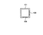
- FIG. 2 is a side view showing a schematic configuration of the slag storage tank shown in FIG.
- FIG. 3 is a side view showing a side surface adjacent to the side surface of the slag storage tank shown in FIG. 2.
- 4 is a cross-sectional view taken along line AA in FIG.
- FIG. 5 is a perspective view showing a schematic configuration of another example of the slag storage tank.
- FIG. 6 is a side view showing a schematic configuration of another example of the slag storage tank.
- FIG. 7 is a side view showing a side surface adjacent to the side surface of the slag storage tank shown in FIG. 6.
- 8 is a cross-sectional view taken along line BB in FIG.
- FIG. 9 is a perspective view showing a schematic configuration of the slag storage tank shown in FIG.
- FIG. 10 is a side view showing a schematic configuration of another example of the slag storage tank.
- FIG. 11 is a side view showing a schematic configuration of another example of the slag storage tank.
- FIG. 12 is a side view showing a schematic configuration of another example of the slag storage tank.
- FIG. 1 is a schematic diagram showing a schematic configuration of an embodiment of a slag discharge system.
- the gasification furnace 12 gasifies a combustion substance such as coal and supplies the generated gas to the combustion furnace or the like.
- the gasification furnace 12 stores the slag generated when the combustion substance is gasified in the slag hopper 14 disposed in the lower part.
- the slag hopper 14 is a storage mechanism that is disposed below the gasification furnace 12, collects the slag generated in the gasification furnace 12, and stores the slag.
- the slag hopper 14 has a funnel shape that decreases in diameter as it goes downward in the vertical direction, and moves the generated slag in one place by moving the slag generated in the gasification furnace 12 downward in the vertical direction. collect.
- the on-off valve 16 is disposed at the lower end in the vertical direction of the slag passage route of the slag hopper 14. The on-off valve 16 switches between starting and stopping discharging of the slag stored in the slag hopper 14 to the slag discharging system 20 by switching between opening and closing.
- the slag discharged from the on-off valve 16 may be solid or fluid.
- the slag discharged from the on-off valve 16 is basically a high-temperature slag and needs to be cooled.
- the transport vehicle 18 is a vehicle that carries the slag discharged from the slag discharge system 20 to a predetermined position.
- a truck can be used as the transport vehicle 18.
- this invention is not limited to this, It can discharge
- the slag discharge system 20 is a system that discharges slag generated in the gasification furnace 12 and discharged from the on-off valve 16 of the slag hopper 14 to the transport vehicle 18.
- the slag discharge system 20 includes a slag lock hopper 22, a slag cooling unit 26, a slag transfer unit 28, a slag storage tank 30, and a discharge port 32.
- the slag lock hopper 22 is a storage part that temporarily stores slag, and is disposed directly below the on-off valve 16.
- the slag lock hopper 22 temporarily stores the slag discharged from the on-off valve 16 and then supplies it to the slag cooling unit 26.
- the slag cooling unit 26 includes a cooling tank 26 a and a transfer conveyor 26 b, cools the slag discharged from the slag lock hopper 22, and then supplies the slag transfer unit 28 to the slag transfer unit 28.
- the cooling tank 26 a is a tank in which a liquid that cools slag such as water is stored, and is disposed directly below the slag lock hopper 22.
- the slag discharged from the slag lock hopper 22 falls into the liquid stored in the cooling tank 26a and is cooled by the liquid.
- the transport conveyor 26b is a transport mechanism that transports the cooled slag dropped into the cooling tank 26a. A part of the conveyor 26 b is disposed in the cooling tank 26 a, holds the slag in the cooling tank 26 a, moves it, and discharges it to the slag conveyor unit 28.
- the slag transport unit 28 is a transport mechanism that transports the slag discharged from the slag cooling unit 26 to the slag storage tank 30, and includes a slurry tank 40, a transport pipe 42, a slurry pump 43, a recovery pipe 62, and a water receiver. Parts 63a and 63b.
- the slurry tank 40 is a tank that stores the slag supplied from the slag cooling unit 26 and water.
- the slurry tank 40 stores slag dispersed in water.
- the transport pipe 42 is a pipe that connects the slurry tank 40 and the slag storage tank 30.
- the slurry pump 43 is disposed in the transport pipe 42, and forms a flow in which water in which the slag in the slurry tank 40 is dispersed flows to the slag storage tank 30.
- the slag transport unit 28 converts the slag dispersed in the water in the slurry tank 40 into a slurry state and transports the slag to the slag storage tank 30 by the transport pipe 42 and the slurry pump 43.
- the recovery pipe 62 is a pipe that collects water discharged from the slag storage tank 30, and connects the water receiving part 63 a and the slurry tank 40, and connects the water receiving part 63 b and the slurry tank 40.
- the water receivers 63 a and 63 b are disposed below the water discharge portion of the slag storage tank 30 and collect the water discharged from the slag storage tank 30.
- the water receivers 63 a and 63 b flow the collected water through the collection pipe 62.
- the water receiving portion 63 a is disposed below the inclined portion of the slag storage tank 30, and the water receiving portion 63 b is disposed below the vertical portion of the slag storage tank 30.
- the slag storage tank 30 is a tank that stores the slag transported by the slag transport unit 28.
- FIG. 2 is a side view showing a schematic configuration of the slag storage tank shown in FIG.
- FIG. 3 is a side view showing a side surface adjacent to the side surface of the slag storage tank shown in FIG. 2.
- 4 is a cross-sectional view taken along line AA in FIG.
- FIG. 5 is a perspective view showing a schematic configuration of another example of the slag storage tank.
- the slag storage tank 30 includes a main body 101, filters 106 and 108, flanges 109 and 110, a lateral reinforcing portion 112, and a vertical reinforcing portion 114.
- the main body 101 is a hollow tower, and in this embodiment, has a cylindrical shape with a square cross section (horizontal surface), and an end portion with a gradually decreasing diameter is provided on the lower side in the vertical direction.
- the filter 106 is a member that does not pass slag but allows water to pass therethrough, and a plurality of the filters 106 are arranged on the side surface (wall surface) of the main body 101.
- the plurality of filters 106 are arranged at respective positions in the vertical direction on one surface of the main body 101.
- the filter 108 is a member that does not pass slag but allows water to pass therethrough, and a plurality of the filters 108 are arranged on the side surface (wall surface) of the main body 101.
- the plurality of filters 108 are disposed at respective positions in the vertical direction on one surface adjacent to the surface on which the filter 106 of the main body 101 is disposed.
- the filters 106 and 108 members in which a plurality of holes having a diameter through which slag cannot pass and water can pass can be used.
- the filter 108 is arranged at a position where the position in the vertical direction is different from that of the filter 106, that is, a position where the position in the vertical direction is deviated from the filters 106 arranged in adjacent rows.
- the filter 108 is arranged in a region including a space between the filter 106 and the filter 106 adjacent to the filter 106 in the vertical direction in the vertical direction. Note that the filter 106 and the filter 108 differ only in the surface on which they are arranged, and the same member can be used for each filter.
- a plurality of baskets 109 are positioned corresponding to the filter 106. Each ridge 109 is arranged immediately below the filter 106 of the main body 101. The eaves 109 collects water discharged from the filter 106 disposed immediately above and transports (discharges) it to the water receiving portions 63a and 63b.
- the connection method of the jar 109 and the water receiving part 63a, 63b is not specifically limited, Both may be connected and the piping which flows water may be provided, or the water discharge part of the jar 109 is used as the water receiving part 63a, It may be arranged directly above 63b, and water may flow through the water receiving portions 63a and 63b by free fall.
- a plurality of jars 110 are positioned corresponding to the filter 108. Each ridge 110 is arranged directly below the filter 108 of the main body 101.
- the jar 110 collects the water discharged from the filter 108 disposed immediately above and transports (discharges) the water to the water receiving portions 63a and 63b.
- the connection method of the coffin 110 and the water receiving part 63a, 63b is not specifically limited, Both may be connected, the piping which flows water may be provided, and the water discharge part of the coffin 110 is used as the water receiving part 63a, It may be arranged directly above 63b, and water may flow through the water receiving portions 63a and 63b by free fall.
- the lateral reinforcing portions 112 are rod-shaped members arranged in the circumferential direction of the main body 101, and a plurality of the horizontal reinforcing portions 112 are arranged on the outer peripheral surface of the main body 101. Further, the vertical reinforcing portion 114 is arranged along the four sides of the main body 101. Note that both ends of the lateral reinforcing portion 112 are connected to separate vertical reinforcing portions 114, respectively. Further, the lateral reinforcing portion 112 is disposed between the filter 106 and the filter 106 and between the filter 108 and the filter 108.
- the lateral reinforcement portion 112 is connected to the lateral reinforcement portion 112 provided on the other surface via the longitudinal reinforcement portion 114, and is connected around the body 101 in the circumferential direction.
- the lateral reinforcement part 112 should just be connected once in the circumferential direction of the main body 101, and the arrangement position is not limited.
- the lateral reinforcing portion 112 is disposed in an area where the filters 106 and 108 are not provided.
- the slag storage tank 30 is configured as described above, and when slag and water are supplied from the slag transport unit 28, only the water is discharged from the filters 106 and 108, and the slag is stored inside.
- the slag storage tank 30 has the filter 106 and the filter 108 arrange
- both the filter 106 and the filter 108 are arranged in a part of a cross section perpendicular to the vertical direction of the main body 101.
- the filter 106 and the filter 108 are arranged in the main body 101 so as to be shifted from each other by a certain distance in the vertical direction.
- the lateral reinforcing portions 112 provided on each surface of the main body 101 are also displaced in the vertical direction according to the displacement of the arrangement positions of the filter 106 and the filter 108. That is, the lateral reinforcing portion 112 is disposed so as not to block the filters 106 and 108.
- the filter 108 is disposed in a region where the filter 106 is not disposed and the filter 106 is disposed in a region where the filter 108 is not disposed in the vertical direction of the slag storage region of the main body 101. It becomes the composition to be done. Further, the filters 106 and 108 are configured not to be blocked by the reinforcing portion.
- region which stores the slag of the main body 101 is an area
- the discharge port 32 is disposed at the lower end of the slag storage tank 30 and controls the execution and stop of the discharge of the slag stored in the slag storage tank 30.
- the slag discharged from the discharge port 32 is discharged to the transport vehicle 18 that is waiting immediately below.
- the slag discharge system 20 is configured as described above, and the slag generated by the gasification furnace 12, recovered by the slag hopper 14, and discharged from the on-off valve 16 is temporarily stored in the slag lock hopper 22.
- the slag discharge system 20 conveys the slag stored in the slag lock hopper 22 to the cooling tank 26a of the slag cooling unit 26, cools it with the cooling tank 26a, and then conveys it to the slurry tank 40 with the conveyer 26b.
- the slag discharge system 20 conveys the slag stored in the slurry tank 40 to the slag storage tank 30 together with water by the transport pipe 42 and the slurry pump 43. Further, the water transported together with the slag to the slag storage tank 30 is discharged from the filters 106 and 108 and falls to the troughs 109 and 110. The water that has dropped into the troughs 109 and 110 is transported to the water receivers 63a and 63b, and is transported to the slurry tank 40 via the recovery pipe 62.
- the slag discharge system 20 continues the above-described slag transport, and stops transporting the slag when the predetermined slag is transported to the slag storage tank 30. Thereafter, the water in the slag storage tank 30 is discharged from the filters 106 and 108 to the eaves 109 and 110, and when the slag in the slag storage tank 30 is dried, the slag is discharged from the discharge port 32 to the transport vehicle 18. Is discharged.
- the transport vehicle 18 loads slag and transports the slag to a predetermined point.
- the transport vehicle 18 sequentially moves directly below the discharge port 32, and moves to a predetermined point after loading the slag.
- the conveyance vehicle 18 repeats conveyance of slag.
- the slag discharge system 20 can convey the slag to the slag storage tank 30 by mixing the slag into water and supplying the slag to the slag storage tank 30 in a slurry state. Since the slag discharge system 20 transports the slag in the form of a slurry, the degree of freedom of the piping path can be increased. That is, the slag can be transported even if the transport path is not linear, and the transport path has an arbitrary inclination angle. Thereby, an apparatus can be arrange
- the slag discharge system 20 is provided with filters 106 and 108 on the side surface of the slag storage tank 30 to discharge water (liquid), thereby efficiently using the water used for conveying the slag from the slag storage tank 30. It can be discharged well and easily.
- the water used for transportation can be used efficiently. Further, even when a part of the slag is discharged from the filters 106 and 108, it can be supplied again to the slag storage tank 30 as slurry, and the slag can be transported more efficiently.
- the slag storage tank 30 of the slag discharge system 20 is provided with the filter 106 and / or the filter 108 at least partially in the cross section perpendicular to the vertical direction of the main body 101. Therefore, even if the liquid level (water surface) reaches any position of the main body 101, the water surface and the filter 106 and / or the filter 108 can be brought into contact with each other. Thereby, the quantity of the water discharged
- the water held in the slurry tank 40 can be kept within a certain range, and the slag of the slurry sent from the slurry tank 40 to the slag storage tank 30 can be reduced.
- the concentration can be within a certain concentration range.
- the slag discharge system 20 can suppress the slag concentration from being increased and the slurry from being unable to be conveyed because the slag concentration in the slurry can be within a certain concentration range.
- the concentration of slag in the slurry can be maintained at 40% or less, and the slag can be appropriately conveyed from the slurry tank 40 to the slag storage tank 30.
- the slag discharge system 20 can convey slag efficiently because the density
- the range of the slag concentration in the slurry is not particularly limited because it varies depending on the configuration of the apparatus, the performance of the pump, and the like. For example, it is preferably 5% to 40%.
- the slag storage tank 30 is provided with reinforcing portions (lateral reinforcing portion 112, vertical reinforcing portion 114), and by reinforcing the wall surface of the main body 101, the strength of the slag storage tank 30 can be increased and durability can be increased. Can be high. Further, the strength of the main body 101 itself can be reduced, and the apparatus cost can be reduced.
- the slag discharge system 20 may control the supply of slag to the slurry tank 40 by controlling the driving of the conveyor 26b of the slag cooling unit 26.
- the supply of slag to the slurry tank 40 may be controlled as being constant.
- the slag discharge system 20 may further include a mechanism for supplying water to the slurry tank 40 and a mechanism for controlling the supply of water. Thereby, the slurry hold
- water is used as the liquid for making the slag into a slurry state, but any liquid other than water may be used as long as it is a liquid.
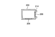
- FIG. 6 is a side view showing a schematic configuration of another example of the slag storage tank.
- 7 is a side view showing a side surface adjacent to the side surface of the slag storage tank shown in FIG. 6,
- FIG. 8 is a sectional view taken along line BB in FIG. 6, and
- FIG. 9 is shown in FIG. It is a perspective view which shows schematic structure of a slag storage tank.
- the slag storage tank 202 includes a main body 203, filters 206 and 208, and a reinforcing portion 212.
- the slag storage tank 202 may further include a jar.
- the main body 203 is a hollow tower, and in this embodiment, has a cylindrical shape with a square cross section (horizontal surface), and an end portion whose diameter gradually decreases is provided on the lower side in the vertical direction.
- a plurality of filters 206 are arranged on the side surface (wall surface) of the main body 203.
- the plurality of filters 206 are arranged at respective positions in the vertical direction on one surface of the main body 203.
- a plurality of filters 208 are arranged on the side surface (wall surface) of the main body 203.
- the plurality of filters 208 are disposed at respective positions in the vertical direction on one surface adjacent to the surface on which the filter 206 of the main body 203 is disposed.
- the single filter 206, 208 has the same configuration as the above-described filters 106, 108.
- the filter 208 is arranged at a position different from the filter 206 in the vertical direction, like the filter 108. Specifically, the filter 208 is disposed in a region including a space between the filter 206 and the filter 206 adjacent to the filter 206 in the vertical direction in the vertical direction.
- the reinforcing portions 212 are rod-shaped members arranged in the circumferential direction of the main body 203, and a plurality of reinforcing portions 212 are arranged on the outer peripheral surface of the main body 203.
- One reinforcing portion 212 is connected once in the circumferential direction of the main body 203. Further, the reinforcing portion 212 is linearly disposed between the filter 206 and the filter 206 on the surface of the main body 203 on which the filter 206 is disposed.
- the reinforcing portion 212 is disposed as a bent U-shaped portion 214 along the periphery of the filter 208 on the surface of the main body 203 on which the filter 208 is disposed.
- the reinforcing portion 212 is basically arranged in a straight line in the circumferential direction of the main body 203, and a portion overlapping with the filter 208 is arranged in a shape bent along the periphery of the filter 208 (U-shaped portion 214). Has been.
- the slag storage tank 202 is configured as described above, and when slag and water are supplied from the slag transport unit 28, only the water is discharged from the filters 206 and 208, and the slag is stored inside.
- a filter 206 and a filter 208 are arranged on different surfaces of the main body 203.
- both the filter 206 and the filter 208 are arranged in a part of a cross section perpendicular to the vertical direction of the main body 203.
- the filter 206 and the filter 208 are arranged in the main body 203 so as to be shifted from each other by a certain distance in the vertical direction.
- the reinforcing portions 212 provided on the respective surfaces of the main body 203 are arranged at positions that do not overlap the filters 206 and 208.
- the strength of the slag storage tank 202 can also be increased by providing the reinforcing portion 212 on the periphery in a shape that avoids the filter as in the slag storage tank 202. Further, even when the filter is provided in a shifted manner, the main body 203 can be reinforced by providing a bent shape like the reinforcing portion 212 without providing a vertical reinforcing portion.
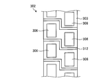
- FIG. 10, FIG. 11, and FIG. 12 are side views each showing a schematic configuration of another example of the slag storage tank.
- 10, 11, and 12 are examples in which a filter is disposed on one surface of the main body.
- the relationship between the filter and the reinforcing portion will be described.
- a plurality of filters 306 and a plurality of filters 308 are arranged on one surface of the main body 303.
- the filters 306 are arranged in a row in the vertical direction, and the filters 308 are also arranged in a row in the vertical direction.
- the filter 306 and the filter 308 are adjacent to each other in the horizontal direction.
- the reinforcing portion 312 is disposed at a position passing between the filter 306 and the adjacent filter 306 and passing between the filter 308 and the adjacent filter 308.
- the reinforcing portion 312 includes a portion that passes between the filter 306 and the adjacent filter 306 and a portion that passes between the filter 308 and the adjacent filter 308 in the vertical direction between the filter 306 and the filter 308. They are connected by extending bar-like parts. Accordingly, the reinforcing portion 312 makes a round in the circumferential direction of the main body 303.
- a plurality of horizontally adjacent filters are provided on one surface, that is, two rows of filters are provided, and one of the horizontally adjacent filters is connected to the other filter. Providing it in a region where it is not arranged can also be configured such that the filter is arranged at any position in the vertical direction.
- the 11 includes a plurality of filters 406 and a plurality of filters 408 arranged on one surface of a main body 403.
- the filters 406 are arranged in a row in the vertical direction, and the filters 408 are also arranged in a row in the vertical direction.
- the filter 406 and the filter 408 are adjacent to each other in the horizontal direction.
- both the filter 406 and the filter 408 are parallelograms, and have a shape in which the area decreases in the vertical direction, in particular, as the end in the vertical direction approaches the end.
- a region where the filter 406 and the filter 408 overlap in the vertical direction is a region in which the area of the filter 406 and the filter 408 changes.
- the reinforcing portion 412 is disposed at a position passing between the filter 406 and the adjacent filter 406 and passing between the filter 408 and the adjacent filter 408. Further, the reinforcing portion 412 is inclined along the edges of the filters 406 and 408 in the vertical direction. Further, the reinforcing portion 412 includes a portion passing between the filter 406 and the adjacent filter 406 and a portion passing between the filter 408 and the adjacent filter 408 in the vertical direction between the filter 406 and the filter 408. They are connected by extending bar-like parts. Accordingly, the reinforcing portion 412 makes a round in the circumferential direction of the main body 403.
- the slag storage tank 402 is provided with a plurality of horizontally adjacent filters on one surface, that is, two rows of filters are provided and are adjacent in the horizontal direction. By providing one filter of the filter in a region where the other filter is not disposed, the filter can be disposed at any position in the vertical direction.
- the slag storage tank 402 has a shape in which the area of the filter changes depending on the position in the vertical direction, so that the filter and the other filter overlap with each other, and the filter and the other filter do not overlap with each other.
- the difference in the area of the filter in the cross section can be reduced.
- the change of the area (area in a cross section) of the filter in the vertical direction can be further reduced, and the change of the amount of water discharged from the slag storage tank 402 can be reduced.
- a plurality of filters 506 are arranged on one surface of the main body 503.
- the filters 506 are arranged in a row in the vertical direction.
- the filter 506 is a parallelogram, and has a shape in which the area becomes smaller as the position in the vertical direction, in particular, the end in the vertical direction goes toward the end.
- a part of the filter 506 is disposed on the same horizontal plane as other filters 506 adjacent in the vertical direction. That is, the filter 506 has an end portion on the lower side in the vertical direction on the lower side in the vertical direction than an end portion on the upper side in the vertical direction of the filter 506 adjacent to the lower side in the vertical direction.
- the filter 506 has an upper end in the vertical direction on the upper side in the vertical direction than an end on the lower side in the vertical direction of the filter 506 adjacent to the upper side in the vertical direction.
- the reinforcing portion 512 is disposed at a position passing between the filter 506 and the adjacent filter 506. Further, the reinforcing portion 512 makes a round in the circumferential direction of the main body 503.
- the slag storage tank 502 is configured such that the filter 506 has a shape in which the area changes according to the position in the vertical direction, in particular, the position in the vertical direction, so that the filter 506 is arranged even when the filters 506 are arranged in a line on one surface.
- the shape in the horizontal direction By adjusting the shape in the horizontal direction, a part of the filter 506 and a part of the adjacent filter 506 can overlap each other in the horizontal direction.
- the slag storage tank can have various configurations for the filter placement position and shape.
- filters may be provided on three or more surfaces of the main body, or may be randomly arranged without being arranged in a line.
- the area of the filter in any cross section is preferably within a certain range, and is a constant value. Is more preferable. That is, the slag storage tank preferably has a smaller amount of change in the area of the filter, which changes depending on the position in the vertical direction.
- the slag storage tank can discharge the liquid conveyed as slurry more stably to the outside by reducing the change in the area of the filter in the vertical direction.
- the slag storage tank and the slag discharge system according to the present invention are useful for storing and discharging slag, and in particular, the slag generated in the combustion furnace is cooled and discharged to a predetermined position. Suitable for
Landscapes
- Chemical & Material Sciences (AREA)
- Engineering & Computer Science (AREA)
- Combustion & Propulsion (AREA)
- Oil, Petroleum & Natural Gas (AREA)
- Organic Chemistry (AREA)
- Mechanical Engineering (AREA)
- General Engineering & Computer Science (AREA)
- Gasification And Melting Of Waste (AREA)
- Filling Or Emptying Of Bunkers, Hoppers, And Tanks (AREA)
Abstract
スラグ貯蔵タンク(30)、及び、スラグ排出システム(20)であって、スラグを貯蔵する本体(101)と、本体(101)の壁面に配置され、液体を選択的に通過させる複数のフィルタ(106、108)と、を有し、本体(101)は、スラグを貯蔵する領域における鉛直方向に垂直ないずれの断面にも少なくとも一部にフィルタ(106、108)が配置することにより、液体を安定して排出することができるスラグ貯蔵タンク(30)、及び、より簡単かつ好適にスラグを排出することができるスラグ排出システム(20)を提供することを目的とする。
Description
本発明は、供給されたスラグを貯蔵し、排出するスラグ貯蔵タンク及びそれを備えるスラグ排出システムに関する。
石炭をガス化して得られた石炭ガスによりガスタービンを駆動して発電する技術がある。石炭をガス化するためには、石炭ガス化炉が使用される。石炭をガス化すると、石炭ガス化炉には燃え滓としてスラグが残る。このようなスラグは、石炭ガス化炉から排出される必要がある。スラグは充分に高温であれば流動性を有するため、一般に、石炭ガス化炉の下部に設けられたスラグホールから連続的に排出される。スラグホールの下方には、冷却水を満たしたスラグ排出筒が設けられ、スラグは、冷却水によって冷却されて固化された後、スラグ排出筒から排出される。
スラグを排出するシステムとしては、特許文献1、特許文献2及び特許文献3に記載されているような装置がある。特許文献1及び特許文献2に記載されている装置は、いずれも、固化したスラグをベルトコンベアにより、貯蔵タンク等に搬送している。また、特許文献3に記載の装置は、ハウジング内に配置され、複数のフライトが装着された軸を回転させることで、スラグをコンテナに搬送する機構が記載されている。また、排出システムには、冷却されたスラグを一時的に貯蔵するスラグ貯蔵タンクを備える構成がある。
ここで、特許文献1から特許文献3に記載されている排出システムは、ベルトコンベアや、スクリューでスラグを搬送する構成である。そのため、コンベアの傾斜角度に限界があったり、コンベア、スクリューを直線上に配置する必要があったりして、装置構成の自由度が低いという問題がある。また、スクレイパや、掻き爪によりスラグを搬送することで、確実に搬送することができるが、1つのスクレイパや、掻き爪による搬送は、搬送量に限界があり、また、搬送が間欠搬送となる。
これに対して、スラグ排出システムには、スラグと液体とを混合してスラリー状にして、スラグ貯蔵タンクに搬送(供給)するシステムがある。このようなシステムのスラグ貯蔵タンクは、スラリーに含まれる液体を選択的に排出するためのフィルタを設け、フィルタから液体を排出し、スラグのみを貯蔵する。このようにフィルタを備えるスラグ貯蔵タンクでは、液体の排出が不安定になる場合がある。また、スラグ貯蔵タンクからの液体の排出が不安定になると、スラグの排出にも影響が生じる。
本発明は、上記に鑑みてなされたものであって、液体を安定して排出することができるスラグ貯蔵タンク、及び、より簡単かつ好適にスラグを排出することができるスラグ排出システムを提供することを目的とする。
上述した課題を解決し、目的を達成するために、本発明は、スラグを貯蔵するスラグ貯蔵タンクであって、スラグを貯蔵する本体と、前記本体の壁面に配置され、液体を選択的に通過させる複数のフィルタと、を有し、前記本体は、前記スラグを貯蔵する領域において、前記壁面の鉛直方向に垂直ないずれの断面も少なくとも一部に前記フィルタが配置されていることを特徴とする。これにより、液体の液面の位置に寄らず、安定して液体を排出することができる。
また、前記本体の外周を一周囲って配置された補強部をさらに有することが好ましい。これにより、装置の強度を向上させることができ、耐久性を高くすることができる。
また、前記本体は、複数の面で構成され、前記フィルタは、前記本体の同一の面に配置されていることが好ましい。これにより、液体を排出させる面を1つにすることができる。
また、前記本体は、複数の面で構成され、前記フィルタは、前記本体の複数の面に配置されていることが好ましい。これにより、設計自由度を高くすることができる。
また、前記本体は、前記スラグを貯蔵する領域における鉛直方向に垂直な断面におけるフィルタの配置割合が、一定の範囲内であることが好ましい。これにより、液体をより安定して排出することができる。
また、上述した課題を解決し、目的を達成するために、本発明は、スラグを貯蔵するスラグ貯蔵タンクであって、スラグを貯蔵する本体と、前記本体の壁面に配置され、液体を選択的に通過させる複数のフィルタと、を有し、前記複数のフィルタは、前記本体の鉛直方向に配置された列が前記本体の水平方向に隣接する位置に配置されており、前記フィルタは、隣接する列に配置された前記フィルタと、前記鉛直方向の位置がずれて配置されていることを特徴とする。これにより、液体の液面の位置に寄らず、安定して液体を排出することができる。
また、上述した課題を解決し、目的を達成するために、本発明は、スラグ排出システムであって、上記のいずれかに記載のスラグ貯蔵タンクと、排出されたスラグを冷却するスラグ冷却部と、前記スラグ冷却部から排出されたスラグと液体とを貯留するスラリータンクと、前記スラリータンクに貯留されたスラグを液体によりスラリー化し、前記スラグ貯蔵タンクに搬送するスラグスラリー搬送部と、前記スラグ貯蔵タンクの前記フィルタから排出された液体を回収し、スラリータンクに供給する回収部と、を有することを特徴とする。これにより、液体の液面の位置に寄らず、安定して液体を排出することができる。液体を適切に循環させることができる。
本発明にかかるスラグ貯蔵タンクは、液体を安定して排出することができるという効果を奏する。また、本発明にかかるスラグ排出システムは、スラグを簡単かつ好適に排出することができるという効果を奏する。
以下、本発明につき図面を参照しつつ詳細に説明する。なお、下記の発明を実施するための形態(以下、実施形態という)により本発明が限定されるものではない。また、下記実施形態における構成要素には、当業者が容易に想定できるもの、実質的に同一のもの、いわゆる均等の範囲のものが含まれる。さらに、下記実施形態で開示した構成要素は適宜組み合わせることが可能である。
以下に、本発明にかかるスラグ排出システムの実施形態を図面に基づいて詳細に説明する。なお、この実施形態によりこの発明が限定されるものではない。
図1は、スラグ排出システムの一実施形態の概略構成を示す模式図である。まず、図1に示すスラグ排出システム20の周囲に配置されている、ガス化炉12、スラグホッパ14、開閉弁16及び搬送車両18について説明する。ガス化炉12は、石炭等の燃焼物質をガス化し、生成したガスを燃焼炉等に供給する。また、ガス化炉12は、燃焼物質をガス化した際に生成されるスラグを下部に配置されたスラグホッパ14に貯留する。スラグホッパ14は、ガス化炉12の下部に配置され、ガス化炉12で生成されたスラグを収集し、スラグを貯留する貯留機構である。なお、スラグホッパ14は、鉛直方向下側に向かうに従って径が小さくなる漏斗形状であり、ガス化炉12で生成されたスラグを鉛直方向下側に移動させることで、生成されたスラグを1箇所に収集する。開閉弁16は、スラグホッパ14のスラグの通過経路の鉛直方向下側の端部に配置されている。開閉弁16は、開閉を切り換えることで、スラグホッパ14に貯留されているスラグのスラグ排出システム20への排出の開始、停止を切り換える。なお、開閉弁16から排出されるスラグは、固体であっても、流体であってもよい。また、開閉弁16から排出されるスラグは、基本的に、高温のスラグであり、冷却する必要がある。
搬送車両18は、スラグ排出システム20から排出されたスラグを所定の位置まで運ぶ車両である。搬送車両18としては、トラックを用いることができる。なお、本実施形態では、搬送車両18に排出する構成としたが、本発明はこれに限定されず、種々の対象に排出することができる。
次に、スラグ排出システム20について説明する。スラグ排出システム20は、ガス化炉12で生成され、スラグホッパ14の開閉弁16から排出されたスラグを搬送車両18に排出するシステムである。スラグ排出システム20は、スラグロックホッパ22と、スラグ冷却部26と、スラグ搬送部28と、スラグ貯蔵タンク30と、排出口32と、を有する。
スラグロックホッパ22は、スラグを一時的に貯留する貯留部であり、開閉弁16の直下に配置されている。スラグロックホッパ22は、開閉弁16から排出されたスラグを一時的に貯留し、その後、スラグ冷却部26に供給する。
スラグ冷却部26は、冷却タンク26aと、搬送コンベア26bとを有し、スラグロックホッパ22から排出されたスラグを冷却した後、スラグ搬送部28に供給する。冷却タンク26aは、水等のスラグを冷却する液体が貯留されたタンクであり、スラグロックホッパ22の直下に配置されている。スラグロックホッパ22から排出されたスラグは、冷却タンク26aに貯留された液体中に落下し、液体により冷却される。搬送コンベア26bは、冷却タンク26a中に落下され、冷却されたスラグを搬送する搬送機構である。搬送コンベア26bは、一部が冷却タンク26a内に配置されており、冷却タンク26a内のスラグを保持し、移動させて、スラグ搬送部28に排出する。
スラグ搬送部28は、スラグ冷却部26から排出されたスラグをスラグ貯蔵タンク30に搬送する搬送機構であり、スラリータンク40と、輸送管42と、スラリーポンプ43と、回収管62と、水受け部63a、63bと、を有する。スラリータンク40は、スラグ冷却部26から供給されたスラグと、水とを貯留するタンクである。スラリータンク40は、水にスラグを分散させた状態で貯留している。輸送管42は、スラリータンク40と、スラグ貯蔵タンク30とを接続する配管である。また、スラリーポンプ43は、輸送管42に配置され、輸送管42に、スラリータンク40内のスラグが分散された水がスラグ貯蔵タンク30に流れる流れを形成する。このように、スラグ搬送部28は、スラリータンク40内の水に分散されたスラグを、スラリー状にして輸送管42とスラリーポンプ43によりスラグ貯蔵タンク30まで搬送する。
回収管62は、スラグ貯蔵タンク30から排出される水を回収する管路であり、水受け部63aとスラリータンク40とを接続させ、水受け部63bとスラリータンク40とを接続させる。水受け部63a、63bは、スラグ貯蔵タンク30の水の排出部分の下方に配置されており、スラグ貯蔵タンク30から排出された水を回収する。水受け部63a、63bは、回収した水を回収管62に流す。なお、水受け部63aは、スラグ貯蔵タンク30の傾斜部分の下方に配置されており、水受け部63bは、スラグ貯蔵タンク30の垂直部分の下方に配置されている。
スラグ貯蔵タンク30は、スラグ搬送部28により搬送されたスラグを貯蔵するタンクである。ここで、図2は、図1に示すスラグ貯蔵タンクの概略構成を示す側面図である。図3は、図2に示すスラグ貯蔵タンクの側面に隣接する側面を示す側面図である。図4は、図2のA-A線断面図である。図5は、スラグ貯蔵タンクの他の例の概略構成を示す斜視図である。スラグ貯蔵タンク30は、図1から図5に示すように、本体101と、フィルタ106、108と、樋109、110と、横補強部112と、縦補強部114と、を有する。本体101は、中空の塔、本実施形態では、断面(水平方向の面)が四角形となる筒形状であり、鉛直方向下側に、径が徐々に小さくなる端部が設けられている。
フィルタ106は、スラグは通過させず、水は通過させる部材であり、本体101の側面(壁面)に複数、配置されている。複数のフィルタ106は、本体101の1つの面の鉛直方向の各位置に配置されている。また、フィルタ108は、フィルタ106と同様に、スラグは通過させず、水は通過させる部材であり、本体101の側面(壁面)に複数、配置されている。複数のフィルタ108は、本体101のフィルタ106が配置されている面に隣接する1つの面の鉛直方向の各位置に配置されている。なお、フィルタ106、108としては、スラグは通過できず、水は通過できる径の穴が複数形成された部材を用いることができる。また、フィルタ108は、鉛直方向における位置がフィルタ106とは異なる位置、つまり隣接した列に配置されたフィルタ106に対して鉛直方向における位置がずれた位置に配置されている。具体的には、フィルタ108は、鉛直方向において、フィルタ106とそのフィルタ106に鉛直方向に隣接するフィルタ106との間を含む領域に配置されている。なお、フィルタ106とフィルタ108とは、配置される面が異なるのみで、各フィルタには、同一の部材を用いることができる。
樋109は、フィルタ106に対応して複数位置されている。それぞれの樋109は、本体101のフィルタ106の直下に配置されている。樋109は、直上に配置されたフィルタ106から排出される水を回収し、水受け部63a、63bに搬送(排出)する。なお、樋109と水受け部63a、63bとの接続方法は特に限定されず、両者を接続し、水を流す配管を設けてもよいし、樋109の水の排出部を水受け部63a、63bの直上に配置し、自由落下で水を水受け部63a、63bに流すようにしてもよい。
樋110は、フィルタ108に対応して複数位置されている。それぞれの樋110は、本体101のフィルタ108の直下に配置されている。樋110は、直上に配置されたフィルタ108から排出される水を回収し、水受け部63a、63bに搬送(排出)する。なお、樋110と水受け部63a、63bとの接続方法は特に限定されず、両者を接続し、水を流す配管を設けてもよいし、樋110の水の排出部を水受け部63a、63bの直上に配置し、自由落下で水を水受け部63a、63bに流すようにしてもよい。
横補強部112は、本体101の周方向に配置された棒状の部材であり、本体101の外周面に複数配置されている。また、縦補強部114は、本体101の4辺に沿って配置されている。なお、横補強部112は、両端がそれぞれ別の縦補強部114に接続されている。また、横補強部112は、フィルタ106とフィルタ106との間、フィルタ108とフィルタ108との間に配置されている。ここで、横補強部112は、縦補強部114を介して、他の面に設けられた横補強部112と接続されており、本体101の周方向に一周連結している。なお、横補強部112は、本体101の周方向に一周連結していればよく、その配置位置は、限定されない。なお、横補強部112は、フィルタ106、108が設けられていない領域に配置されている。
スラグ貯蔵タンク30は、以上のような構成であり、スラグ搬送部28からスラグ及び水が供給されたら、フィルタ106、108から水のみを排出し、内部にスラグを貯蔵する。また、スラグ貯蔵タンク30は、図2及び図3に示すように、本体101の別々の面にそれぞれフィルタ106と、フィルタ108とが配置されている。また、図4に示すように本体101の鉛直方向に垂直な断面の一部は、フィルタ106とフィルタ108の両方が配置されている。これにより、図5に示すように、本体101には、フィルタ106と、フィルタ108とが、鉛直方向に一定距離ずれて配置されている。また、本体101の各面に設けられている横補強部112も、フィルタ106と、フィルタ108の配置位置のずれに応じて、鉛直方向にずれて配置されている。つまり、横補強部112が、フィルタ106、108を塞がないように配置されている。
これにより、スラグ貯蔵タンク30は、本体101のスラグを貯蔵する領域の鉛直方向において、フィルタ106が配置されていない領域にフィルタ108が配置され、フィルタ108が配置されていない領域にフィルタ106が配置される構成となる。また、フィルタ106、108が補強部により塞がれない構成となる。なお、本体101のスラグを貯蔵する領域とは、スラグが実質的に貯留される領域であり、本体101の上端の一部や下端の一部は、含まない。
排出口32は、スラグ貯蔵タンク30の下方の端部に配置されており、スラグ貯蔵タンク30に貯蔵されているスラグの排出の実行、停止を制御する。排出口32から排出されたスラグは、直下に待機している搬送車両18に排出される。
スラグ排出システム20は、以上のような構成であり、ガス化炉12で生成され、スラグホッパ14で回収され、開閉弁16から排出されたスラグをスラグロックホッパ22に一時的に貯留する。スラグ排出システム20は、スラグロックホッパ22に貯留したスラグをスラグ冷却部26の冷却タンク26aに搬送し、冷却タンク26aで冷却した後、搬送コンベア26bでスラリータンク40に搬送する。
スラグ排出システム20は、輸送管42とスラリーポンプ43により、スラリータンク40に貯留されたスラグを水と共にスラグ貯蔵タンク30に搬送する。また、スラグ貯蔵タンク30にスラグとともに搬送された水は、フィルタ106、108から排出され、樋109、110に落下する。樋109、110に落下した水は、水受け部63a、63bに搬送され、回収管62を介してスラリータンク40に搬送される。
スラグ排出システム20は、上述したスラグの搬送を継続し、スラグ貯蔵タンク30に所定のスラグを搬送したら、スラグの搬送を停止する。その後、スラグ排出システム20は、スラグ貯蔵タンク30内の水が、フィルタ106、108から樋109、110に排出され、スラグ貯蔵タンク30内のスラグが乾燥したら、排出口32から搬送車両18にスラグを排出する。搬送車両18は、スラグを積載し、所定の地点までスラグを搬送する。なお、搬送車両18は、順次、排出口32の直下に移動し、スラグを積載したら、所定の地点まで移動する。このように、搬送車両18は、スラグの搬送を繰り返す。
このように、スラグ排出システム20は、スラグを水に混入し、スラリー状にしてスラグ貯蔵タンク30に供給することで、スラグをスラグ貯蔵タンク30に搬送することができる。スラグ排出システム20は、スラリー状にしてスラグを搬送するため、配管の経路の自由度を高くすることができる。つまり、搬送経路が直線状でなくても、また、搬送経路の傾斜角が任意の角度であっても、スラグを搬送することができる。これにより、装置をコンパクトに配置することができる。
また、スラグ排出システム20は、スラグ貯蔵タンク30の側面にフィルタ106、108を設け、水(液体)を排出する構成とすることで、スラグ貯蔵タンク30から、スラグの搬送に利用した水を効率よく、かつ、簡単に排出することができる。また、スラグ貯蔵タンク30のフィルタ106、108から排出した水を回収し、スラリータンク40に戻すことで、搬送に使用する水を効率よく利用することができる。また、フィルタ106、108から一部のスラグが排出されてしまった場合も、再びスラグ貯蔵タンク30にスラリーとして供給することができ、スラグをより無駄なく、搬送することができる。
さらに、スラグ排出システム20のスラグ貯蔵タンク30は、本体101の鉛直方向に垂直な断面には、少なくとも一部に、フィルタ106及び/またはフィルタ108が配置されている。従って、本体101のいずれの位置に液面(水面)が到達しても、水面とフィルタ106及び/またはフィルタ108とを接触させることができる。これにより、スラグ貯蔵タンク30から排出する水の量を安定させることができる。つまり、スラグ貯蔵タンク30からスラリータンク40に供給される(戻される)水の量を安定させることができる。このように、スラグ貯蔵タンク30からの水の回収量を安定させることで、スラリータンク40で保持する水を一定範囲にすることができ、スラリータンク40からスラグ貯蔵タンク30に送るスラリーのスラグの濃度を一定濃度範囲内とすることができる。
このように、スラグ排出システム20は、スラリー内のスラグの濃度を一定濃度範囲内にできることで、スラグの濃度が高くなり、スラリーを搬送できなくなることを抑制することができる。例えば、スラリー内のスラグの濃度を40%以下に維持することができ、スラリータンク40からスラグ貯蔵タンク30に適切にスラグを搬送することができる。また、スラグ排出システム20は、スラリー内のスラグの濃度を一定濃度範囲内にできることで、スラグを効率よく搬送することができる。つまり、スラリーに含まれるスラグの量が少なくなり、搬送効率が低下することを抑制することができる。なお、スラリー内のスラグの濃度の範囲は、装置の構成や、ポンプの性能等によって種々の値となるため、特に限定されないが、例えば、5%から40%にすることが好ましい。
また、スラグ貯蔵タンク30は、補強部(横補強部112、縦補強部114)を設け、本体101の壁面を補強することで、スラグ貯蔵タンク30の強度を高くすることができ、耐久性を高くすることができる。また、本体101自体の強度を低くすることができ、装置コストを低減することができる。
スラグ排出システム20は、スラグ冷却部26の搬送コンベア26bの駆動を制御することで、スラリータンク40へのスラグの供給を制御してもよい。また、スラリータンク40へのスラグの供給は一定として制御を行ってもよい。また、スラグ排出システム20は、さらに、スラリータンク40に水を供給する機構を設け、水の供給を制御する機構を設けてもよい。これにより、スラリータンク40に保持されるスラリーをより適切に制御することができる。
なお、本実施形態では、スラグをスラリー状にするための液体として、水を用いたが、液体であればよく、水以外の液体も用いることができる。
ここで、スラグ貯蔵タンクは、上記実施形態に限定されない。以下、図6から図9を用いてスラグ貯蔵タンクの他の例について説明する。図6は、スラグ貯蔵タンクの他の例の概略構成を示す側面図である。また、図7は、図6に示すスラグ貯蔵タンクの側面に隣接する側面を示す側面図であり、図8は、図6のB-B線断面図であり、図9は、図6に示すスラグ貯蔵タンクの概略構成を示す斜視図である。スラグ貯蔵タンク202は、図6から図9に示すように、本体203と、フィルタ206、208と、補強部212とを有する。なお、スラグ貯蔵タンク202は、さらに樋を備えていてもよい。本体203は、中空の塔、本実施形態では、断面(水平方向の面)が四角形となる筒形状であり、鉛直方向下側に、径が徐々に小さくなる端部が設けられている。
フィルタ206は、本体203の側面(壁面)に複数、配置されている。複数のフィルタ206は、本体203の1つの面の鉛直方向の各位置に配置されている。また、フィルタ208は、本体203の側面(壁面)に複数、配置されている。複数のフィルタ208は、本体203のフィルタ206が配置されている面に隣接する1つの面の鉛直方向の各位置に配置されている。なお、1枚のフィルタ206、208は、上述したフィルタ106、108と同様の構成である。
また、フィルタ208は、フィルタ108と同様に、鉛直方向における位置がフィルタ206とは、異なる位置に配置されている。具体的には、フィルタ208は、鉛直方向において、フィルタ206とそのフィルタ206に鉛直方向に隣接するフィルタ206との間を含む領域に配置されている。
補強部212は、本体203の周方向に配置された棒状の部材であり、本体203の外周面に複数配置されている。1つの補強部212は、本体203の周方向に一周連結している。また、補強部212は、本体203のフィルタ206が配置されている面では、フィルタ206とフィルタ206との間に直線状に配置されている。補強部212は、本体203のフィルタ208が配置されている面では、フィルタ208の周りに沿って、折れ曲がったU字部214として配置されている。つまり、補強部212は、基本的に、本体203の周方向に直線上に配置されており、フィルタ208と重なる部分は、フィルタ208の周囲に沿って折れ曲がった形状(U字部214)で配置されている。
スラグ貯蔵タンク202は、以上のような構成であり、スラグ搬送部28からスラグ及び水が供給されたら、フィルタ206、208から水のみを排出し、内部にスラグを貯蔵する。また、スラグ貯蔵タンク202も、図6及び図7に示すように、本体203の別々の面にそれぞれフィルタ206と、フィルタ208とが配置されている。また、図8に示すように本体203の鉛直方向に垂直な断面の一部は、フィルタ206とフィルタ208の両方が配置されている。これにより、図9に示すように、本体203には、フィルタ206と、フィルタ208とが、鉛直方向に一定距離ずれて配置されている。また、本体203の各面に設けられている補強部212は、フィルタ206、208と重ならない位置に配置されている。
スラグ貯蔵タンク202のように、補強部212を、フィルタを避ける形状で周上に設けることでも、スラグ貯蔵タンク202の強度を高くすることができる。また、フィルタをずらして設けた場合でも、補強部212のように、屈曲した形状とすることで、縦補強部を設けることなく、本体203を補強することができる。
次に、図10から図12を用いて、スラグ貯蔵タンクのさらに他の例を説明する。ここで、図10、図11、図12は、それぞれ、スラグ貯蔵タンクの他の例の概略構成を示す側面図である。なお、図10、図11、図12は、本体の1つの面にフィルタを配置した例である。以下、フィルタと補強部との関係について説明する。
図10に示すスラグ貯蔵タンク302は、本体303の1つの面に、複数のフィルタ306と、複数のフィルタ308とが配置されている。なお、フィルタ306は、鉛直方向に列状に配置され、フィルタ308も、鉛直方向に列状に配置されている。また、フィルタ306とフィルタ308とは、水平方向に隣接している。
また、補強部312は、フィルタ306と隣接するフィルタ306との間を通り、かつ、フィルタ308と隣接するフィルタ308との間を通る位置に配置されている。また、補強部312は、フィルタ306と隣接するフィルタ306との間を通る部分と、フィルタ308と隣接するフィルタ308との間を通る部分とが、フィルタ306とフィルタ308との間に鉛直方向に延びる棒状部で接続されている。これにより、補強部312は、本体303の周方向に一周している。
スラグ貯蔵タンク302に示すように、1つの面に水平方向に隣接したフィルタを複数設け、つまり、2つの列状のフィルタを設け、水平方向に隣接するフィルタの一方のフィルタを、他方のフィルタが配置されていない領域に設けることでも、鉛直方向のどの位置にもフィルタが配置された構成とすることができる。
図11に示すスラグ貯蔵タンク402は、本体403の1つの面に、複数のフィルタ406と、複数のフィルタ408とが配置されている。なお、フィルタ406は、鉛直方向に列状に配置され、フィルタ408も、鉛直方向に列状に配置されている。また、フィルタ406とフィルタ408とは、水平方向に隣接している。ここで、フィルタ406とフィルタ408は、共に、平行四辺形であり、鉛直方向の位置、特に、上下方向の端部が端部に向かうに従って面積が小さくなる形状となっている。また、フィルタ406とフィルタ408は、鉛直方向において、フィルタ406とフィルタ408とが重なる領域が、自身の面積が変化している領域となる。
また、補強部412は、フィルタ406と隣接するフィルタ406との間を通り、かつ、フィルタ408と隣接するフィルタ408との間を通る位置に配置されている。また、補強部412は、フィルタ406、408の鉛直方向の端の辺に沿って傾斜している。また、補強部412は、フィルタ406と隣接するフィルタ406との間を通る部分と、フィルタ408と隣接するフィルタ408との間を通る部分とが、フィルタ406とフィルタ408との間に鉛直方向に延びる棒状部で接続されている。これにより、補強部412は、本体403の周方向に一周している。
スラグ貯蔵タンク402は、上述したスラグ貯蔵タンク30、202、302と同様に、1つの面に水平方向に隣接したフィルタを複数設け、つまり、2つの列状のフィルタを設け、水平方向に隣接するフィルタの一方のフィルタを、他方のフィルタが配置されていない領域に設けることで、鉛直方向のどの位置にもフィルタが配置された構成とすることができる。
さらに、スラグ貯蔵タンク402は、フィルタの形状を鉛直方向の位置に応じて面積が変わる形状とすることで、フィルタと他のフィルタとが重なる領域と、フィルタと他のフィルタとが重ならない領域との、断面におけるフィルタの面積の差を小さくすることができる。これにより、鉛直方向におけるフィルタの面積(断面での面積)の変化をより少なくすることができ、スラグ貯蔵タンク402から排出される水の量の変化を小さくすることができる。
図12に示すスラグ貯蔵タンク502は、本体503の1つの面に、複数のフィルタ506が配置されている。フィルタ506は、鉛直方向に列状に配置されている。フィルタ506は、平行四辺形であり、鉛直方向の位置、特に、上下方向の端部が端部に向かうに従って面積が小さくなる形状となっている。また、フィルタ506は、一部が、鉛直方向に隣接する他のフィルタ506と同一水平面上に配置されている。つまり、フィルタ506は、鉛直方向下側の端部が、鉛直方向下側に隣接するフィルタ506の鉛直方向上側の端部よりも、鉛直方向下側にある。フィルタ506は、鉛直方向上側の端部が、鉛直方向上側に隣接するフィルタ506の鉛直方向下側の端部よりも、鉛直方向上側にある。
また、補強部512は、フィルタ506と隣接するフィルタ506との間を通る位置に配置されている。また、補強部512は、本体503の周方向に一周している。
スラグ貯蔵タンク502は、フィルタ506を、鉛直方向の位置、特に、上下方向の位置に応じて面積が変化する形状とすることで、1つの面に一列でフィルタ506を配置した場合も、フィルタ506の水平方向における形状を調整することで、フィルタ506の一部と隣接するフィルタ506の一部とが水平方向において重なる形状とすることができる。
このように、スラグ貯蔵タンクは、フィルタの配置位置、形状は、種々の構成とすることができる。なお、スラグ貯蔵タンクは、フィルタを本体の3つ以上の面に設けてもよいし、列状に配置せずに、ランダムに配置してもよい。
なお、スラグ貯蔵タンクは、本体の鉛直方向に直交する断面において、いずれの断面においても、フィルタの面積が、つまり、断面においてフィルタが占める割合が一定範囲であることが好ましく、一定値であることがより好ましい。すなわち、スラグ貯蔵タンクは、鉛直方向の位置によって変化する、フィルタの面積の変化量をより小さくすることが好ましい。スラグ貯蔵タンクは、鉛直方向におけるフィルタの面積の変化を少なくすることで、スラリーとして搬送された液体をより安定して外部に排出することができる。
以上のように、本発明にかかるスラグ貯蔵タンク及びスラグ排出システムは、スラグを貯蔵、排出するのに有用であり、特に、燃焼炉で生成されたスラグを冷却し、所定の位置に排出するのに適している。
12 ガス化炉
14 スラグホッパ
16 開閉弁
18 搬送車両
20 スラグ排出システム
22 スラグロックホッパ
26 スラグ冷却部
26a 冷却タンク
26b 搬送コンベア
28 スラグ搬送部
30 スラグ貯蔵タンク
32 排出口
40 スラリータンク
42 輸送管
43 スラリーポンプ
62 回収管
63a、63b 水受け部
101 本体
106、108 フィルタ
109、110 樋
112 横補強部
114 縦補強部
14 スラグホッパ
16 開閉弁
18 搬送車両
20 スラグ排出システム
22 スラグロックホッパ
26 スラグ冷却部
26a 冷却タンク
26b 搬送コンベア
28 スラグ搬送部
30 スラグ貯蔵タンク
32 排出口
40 スラリータンク
42 輸送管
43 スラリーポンプ
62 回収管
63a、63b 水受け部
101 本体
106、108 フィルタ
109、110 樋
112 横補強部
114 縦補強部
Claims (7)
- スラグを貯蔵するスラグ貯蔵タンクであって、
スラグを貯蔵する本体と、
前記本体の壁面に配置され、液体を選択的に通過させる複数のフィルタと、を有し、
前記本体は、前記スラグを貯蔵する領域において、前記壁面の鉛直方向に垂直ないずれの断面も少なくとも一部に前記フィルタが配置されていることを特徴とするスラグ貯蔵タンク。 - 前記本体の外周を一周囲って配置された補強部をさらに有することを特徴とする請求項1に記載のスラグ貯蔵タンク。
- 前記本体は、複数の面で構成され、
前記フィルタは、前記本体の同一の面に配置されていることを特徴とする請求項1または2に記載のスラグ貯蔵タンク。 - 前記本体は、複数の面で構成され、
前記フィルタは、前記本体の複数の面に配置されていることを特徴とする請求項1または2に記載のスラグ貯蔵タンク。 - 前記本体は、前記スラグを貯蔵する領域における鉛直方向に垂直な断面におけるフィルタの配置割合が、一定の範囲内であることを特徴とする請求項1から4のいずれか1項に記載のスラグ貯蔵タンク。
- スラグを貯蔵するスラグ貯蔵タンクであって、
スラグを貯蔵する本体と、
前記本体の壁面に配置され、液体を選択的に通過させる複数のフィルタと、を有し、
前記複数のフィルタは、前記本体の鉛直方向に配置された列が前記本体の水平方向に隣接する位置に配置されており、
前記フィルタは、隣接する列に配置された前記フィルタと、前記鉛直方向の位置がずれて配置されていることを特徴とするスラグ貯蔵タンク。 - 請求項1から6のいずれか1項に記載のスラグ貯蔵タンクと、
排出されたスラグを冷却するスラグ冷却部と、
前記スラグ冷却部から排出されたスラグと液体とを貯留するスラリータンクと、
前記スラリータンクに貯留されたスラグを液体によりスラリー化し、前記スラグ貯蔵タンクに搬送するスラグスラリー搬送部と、
前記スラグ貯蔵タンクの前記フィルタから排出された液体を回収し、スラリータンクに供給する回収部と、を有することを特徴とするスラグ排出システム。
Priority Applications (1)
| Application Number | Priority Date | Filing Date | Title |
|---|---|---|---|
| US13/812,021 US20130126414A1 (en) | 2010-08-10 | 2011-08-10 | Slag storage tank and slag discharge system |
Applications Claiming Priority (2)
| Application Number | Priority Date | Filing Date | Title |
|---|---|---|---|
| JP2010179875A JP5517823B2 (ja) | 2010-08-10 | 2010-08-10 | スラグ貯蔵タンク及びスラグ排出システム |
| JP2010-179875 | 2010-08-10 |
Publications (1)
| Publication Number | Publication Date |
|---|---|
| WO2012020804A1 true WO2012020804A1 (ja) | 2012-02-16 |
Family
ID=45567766
Family Applications (1)
| Application Number | Title | Priority Date | Filing Date |
|---|---|---|---|
| PCT/JP2011/068300 Ceased WO2012020804A1 (ja) | 2010-08-10 | 2011-08-10 | スラグ貯蔵タンク及びスラグ排出システム |
Country Status (3)
| Country | Link |
|---|---|
| US (1) | US20130126414A1 (ja) |
| JP (1) | JP5517823B2 (ja) |
| WO (1) | WO2012020804A1 (ja) |
Cited By (1)
| Publication number | Priority date | Publication date | Assignee | Title |
|---|---|---|---|---|
| CN110512037A (zh) * | 2019-09-25 | 2019-11-29 | 中冶沈勘秦皇岛工程设计研究总院有限公司 | 熔渣收送设备及熔渣收送方法 |
Citations (3)
| Publication number | Priority date | Publication date | Assignee | Title |
|---|---|---|---|---|
| JPS53140286U (ja) * | 1977-04-11 | 1978-11-06 | ||
| JPS58183202U (ja) * | 1982-05-27 | 1983-12-06 | 石川島播磨重工業株式会社 | 水砕製造設備の脱水装置 |
| JP2008230921A (ja) * | 2007-03-22 | 2008-10-02 | Takuma Co Ltd | 溶融スラグの水砕処理方法とその装置 |
Family Cites Families (3)
| Publication number | Priority date | Publication date | Assignee | Title |
|---|---|---|---|---|
| US5785851A (en) * | 1996-08-23 | 1998-07-28 | Vesuvius Crucible Company | High capacity filter |
| US8728328B2 (en) * | 2007-10-23 | 2014-05-20 | General Electric Company | Methods for removing suspended solids from a gasification process stream |
| MX2012003162A (es) * | 2009-09-15 | 2012-09-07 | Purolator Filters Na Llc | Filtro con elementos de filtro principal y suplemental y rompedor de burbujas opcional. |
-
2010
- 2010-08-10 JP JP2010179875A patent/JP5517823B2/ja active Active
-
2011
- 2011-08-10 WO PCT/JP2011/068300 patent/WO2012020804A1/ja not_active Ceased
- 2011-08-10 US US13/812,021 patent/US20130126414A1/en not_active Abandoned
Patent Citations (3)
| Publication number | Priority date | Publication date | Assignee | Title |
|---|---|---|---|---|
| JPS53140286U (ja) * | 1977-04-11 | 1978-11-06 | ||
| JPS58183202U (ja) * | 1982-05-27 | 1983-12-06 | 石川島播磨重工業株式会社 | 水砕製造設備の脱水装置 |
| JP2008230921A (ja) * | 2007-03-22 | 2008-10-02 | Takuma Co Ltd | 溶融スラグの水砕処理方法とその装置 |
Cited By (1)
| Publication number | Priority date | Publication date | Assignee | Title |
|---|---|---|---|---|
| CN110512037A (zh) * | 2019-09-25 | 2019-11-29 | 中冶沈勘秦皇岛工程设计研究总院有限公司 | 熔渣收送设备及熔渣收送方法 |
Also Published As
| Publication number | Publication date |
|---|---|
| JP5517823B2 (ja) | 2014-06-11 |
| JP2012035995A (ja) | 2012-02-23 |
| US20130126414A1 (en) | 2013-05-23 |
Similar Documents
| Publication | Publication Date | Title |
|---|---|---|
| WO2011040112A1 (ja) | スラグ排出システム | |
| CA2978271A1 (en) | On-location sand delivery system & conveyor and process | |
| AU2005270520B2 (en) | Device and method for pneumatically conveying bulk materials in a dense flow method | |
| EA014359B1 (ru) | Устройство для транспортировки порошковых материалов | |
| JP2013112483A (ja) | ベルトコンベヤ装置の制御方法並びにベルトコンベヤ設備 | |
| KR20130069579A (ko) | 미세립 연료를 다수의 버너에 공급하기 위한 장치 | |
| JP5517823B2 (ja) | スラグ貯蔵タンク及びスラグ排出システム | |
| JP2009214577A (ja) | 全方位積込可能システム | |
| KR101194757B1 (ko) | 친환경 저탄소 배치 플랜트를 위한 레미콘 공장의 지하 골재 저장 장치 | |
| JP5601932B2 (ja) | スラグ排出システム | |
| KR101355663B1 (ko) | 석탄 화력발전소에서의 플라이 애쉬 핸들링 시스템 | |
| JP2013203515A (ja) | 落炭搬送装置 | |
| CN105452098B (zh) | 船舶、船舶的装货方法及船舶的卸货方法 | |
| FI82015C (fi) | Transportraenna foer transport av pulverformig eller finfoerdelad bulkvara och foerfarande foer att driva densamma. | |
| JP5535868B2 (ja) | スラグ排出システムおよびスラグ排出システムの運転方法 | |
| KR100796068B1 (ko) | 선박용 탱크의 저장물 침전방지 구조 | |
| JP2013203499A (ja) | 粉体貯留排出装置 | |
| CN101992954A (zh) | 低置仓储料仓的卸料设备 | |
| TW202039058A (zh) | 流體輸送裝置及流體輸送裝置的改造方法 | |
| EA012711B1 (ru) | Способ и устройство для загрузки перерабатывающих установок | |
| EA019948B1 (ru) | Устройство для транспортировки сыпучих материалов | |
| JP2006153120A (ja) | ガスハイドレートペレット移送装置と移送方法 | |
| RU2476364C1 (ru) | Нагнетательная пневмотранспортная установка | |
| JP6056034B2 (ja) | 揚荷装置 | |
| JP4645940B2 (ja) | 船倉内ばら物の搬出装置 |
Legal Events
| Date | Code | Title | Description |
|---|---|---|---|
| 121 | Ep: the epo has been informed by wipo that ep was designated in this application |
Ref document number: 11816468 Country of ref document: EP Kind code of ref document: A1 |
|
| WWE | Wipo information: entry into national phase |
Ref document number: 13812021 Country of ref document: US |
|
| NENP | Non-entry into the national phase |
Ref country code: DE |
|
| 122 | Ep: pct application non-entry in european phase |
Ref document number: 11816468 Country of ref document: EP Kind code of ref document: A1 |