WO2012020608A1 - 湿式画像形成装置 - Google Patents
湿式画像形成装置 Download PDFInfo
- Publication number
- WO2012020608A1 WO2012020608A1 PCT/JP2011/064646 JP2011064646W WO2012020608A1 WO 2012020608 A1 WO2012020608 A1 WO 2012020608A1 JP 2011064646 W JP2011064646 W JP 2011064646W WO 2012020608 A1 WO2012020608 A1 WO 2012020608A1
- Authority
- WO
- WIPO (PCT)
- Prior art keywords
- cleaning liquid
- cleaning
- roller
- tank
- forming apparatus
- Prior art date
- Legal status (The legal status is an assumption and is not a legal conclusion. Google has not performed a legal analysis and makes no representation as to the accuracy of the status listed.)
- Ceased
Links
Images


Classifications
-
- G—PHYSICS
- G03—PHOTOGRAPHY; CINEMATOGRAPHY; ANALOGOUS TECHNIQUES USING WAVES OTHER THAN OPTICAL WAVES; ELECTROGRAPHY; HOLOGRAPHY
- G03G—ELECTROGRAPHY; ELECTROPHOTOGRAPHY; MAGNETOGRAPHY
- G03G21/00—Arrangements not provided for by groups G03G13/00 - G03G19/00, e.g. cleaning, elimination of residual charge
- G03G21/0094—Arrangements not provided for by groups G03G13/00 - G03G19/00, e.g. cleaning, elimination of residual charge fatigue treatment of the photoconductor
-
- G—PHYSICS
- G03—PHOTOGRAPHY; CINEMATOGRAPHY; ANALOGOUS TECHNIQUES USING WAVES OTHER THAN OPTICAL WAVES; ELECTROGRAPHY; HOLOGRAPHY
- G03G—ELECTROGRAPHY; ELECTROPHOTOGRAPHY; MAGNETOGRAPHY
- G03G21/00—Arrangements not provided for by groups G03G13/00 - G03G19/00, e.g. cleaning, elimination of residual charge
- G03G21/0005—Arrangements not provided for by groups G03G13/00 - G03G19/00, e.g. cleaning, elimination of residual charge for removing solid developer or debris from the electrographic recording medium
- G03G21/0011—Arrangements not provided for by groups G03G13/00 - G03G19/00, e.g. cleaning, elimination of residual charge for removing solid developer or debris from the electrographic recording medium using a blade; Details of cleaning blades, e.g. blade shape, layer forming
Definitions
- the present invention relates to an electrophotographic image forming apparatus, and more particularly to a wet type image forming apparatus that forms an image using a liquid developer in which toner is dispersed in a carrier liquid.
- an electrostatic latent image formed on a photoreceptor is developed with toner, and the toner image is transferred to a recording sheet to form an image.
- the toner image is temporarily transferred from the photosensitive member to the intermediate transfer member and then secondarily transferred from the intermediate transfer member to the recording paper to form an image. become.
- an electrostatic transfer method is generally employed.
- a voltage is applied to the intermediate transfer member disposed so as to face the photosensitive member, and the photosensitive member, the intermediate transfer member, An electric field is formed between the toner image and the toner image is electrostatically attracted to the intermediate transfer member by this electric field.
- a voltage is applied by a transfer roller or the like from the back surface of the sheet disposed so as to face the intermediate transfer member, and the intermediate transfer member and the sheet An electric field is formed between the toner image and the toner image electrostatically attracted to the paper by this electric field.
- Japanese Patent Laid-Open No. 2002-132106 discloses a configuration in which the cleaning liquid is applied to the photosensitive member from the cleaning roller immersed in the cleaning liquid. However, when the cleaning liquid is applied, the toner also adheres to the cleaning roller side. Therefore, when used repeatedly, the concentration of the toner particles contained in the cleaning liquid may increase.
- the present invention has been made to solve the above-described problems, and is a wet image formation capable of ensuring good cleaning properties by suppressing the concentration of toner particles contained in a cleaning liquid.
- An object is to provide an apparatus.
- a wet image forming apparatus is a wet image forming apparatus that forms a toner image on an image carrier using a liquid developer in which toner is dispersed in a carrier liquid, and the toner on the image carrier.
- a cleaning blade for removing an image a cleaning roller that is provided upstream of the cleaning blade in the rotation direction of the image carrier, and that applies a cleaning liquid to the image carrier, and supplies the cleaning liquid to the cleaning roller
- a recovery means for recovering excess cleaning liquid containing toner particles after the cleaning roller has applied the cleaning liquid to the image carrier.
- the recovery means sends the cleaning liquid purified by removing the toner particles from the recovered cleaning liquid to the cleaning liquid supply unit.
- the recovery means recovers the cleaning liquid at a position upstream of the cleaning roller in the rotational direction, and the cleaning liquid supply unit downstream from the recovery position. Is provided.
- a cleaning liquid storage tank is provided so as to cover the cleaning roller and store excess cleaning liquid containing toner particles dripped from the cleaning roller, and at a rotational position after the cleaning roller comes into contact with the image carrier, The cleaning roller is immersed in the cleaning liquid stored in the cleaning liquid storage tank.
- the cleaning liquid storage tank further includes a screw for forming a flow in a direction opposite to the direction of the cleaning liquid flow generated in the cleaning liquid storage tank in accordance with the rotation direction of the cleaning roller.
- the cleaning liquid supply unit supplies the cleaning liquid to the cleaning liquid storage tank.
- the cleaning liquid storage tank is separated into a first cleaning liquid tank surrounded by the cleaning roller and the cleaning liquid storage tank, and a second cleaning liquid tank surrounded by the cleaning roller and the cleaning liquid storage tank.
- the cleaning liquid supply unit supplies the cleaning liquid to the first cleaning liquid tank, and the recovery means recovers excess cleaning liquid including toner particles from the second cleaning liquid tank.
- the cleaning liquid storage tank includes a partition plate provided in contact with the cleaning roller to separate the first cleaning liquid tank and the second cleaning liquid tank.
- the partition plate has a first region where the tip abuts on the cleaning roller, and a second region where the tip is higher than the height of the first region.
- the cleaning liquid supply unit supplies the cleaning liquid so as to drop directly on the surface of the cleaning roller.
- a wet image forming apparatus includes a cleaning roller that applies a cleaning liquid to an image carrier, a cleaning liquid supply unit that supplies the cleaning liquid to the cleaning roller, and the cleaning roller as an image carrier.
- Recovery means for recovering excess cleaning liquid containing toner particles after application.
- the recovery means sends the cleaning liquid purified by removing the toner particles from the recovered liquid to the cleaning liquid supply unit. Therefore, since the cleaned cleaning liquid is supplied to the cleaning roller, the concentration of toner particles contained in the cleaning liquid can be suppressed and good cleaning performance can be ensured.
- FIG. 1 is a schematic configuration diagram showing an example of a wet image forming apparatus according to an embodiment of the present invention. It is the schematic explaining the structure of the cleaning apparatus 12 according to embodiment of this invention. It is a figure explaining the structure of the cleaning apparatus according to the modification 1 of embodiment of this invention. It is a figure explaining the structure of the cleaning apparatus according to the modification 2 of embodiment of this invention. It is a figure explaining the structure of the cleaning apparatus according to the modification 3 of embodiment of this invention. It is a figure explaining the structure of the cleaning apparatus according to the modification 4 of embodiment of this invention. It is a figure explaining the relationship between the partition plate and the cleaning roller according to the modification 4 of embodiment of this invention.
- a wet image forming apparatus will be described as a representative example of the image forming apparatus.
- FIG. 1 is a schematic configuration diagram showing an example of a wet image forming apparatus according to an embodiment of the present invention.
- the wet image forming apparatus according to the first embodiment of the present invention is provided with a photoreceptor 2 that is a drum-shaped image carrier, and a rotation direction a indicated by an arrow around the photoreceptor 2.
- the developing roller 18, the pressure roller 10, the cleaning device 12, the eraser lamp 14, the charging device 4 and the exposure device 6 of the developing device are arranged in this order.
- the surface of the photoreceptor 2 is uniformly charged to a predetermined surface potential by the charging device 4. Thereafter, image information is exposed by the exposure device 6 to form an electrostatic latent image on the surface of the photoreceptor 2.
- the electrostatic latent image on the photoreceptor 2 is developed with a liquid developer in which toner particles are dispersed in a carrier liquid by the developing roller 18 of the developing device, and a toner image is formed on the surface of the photoreceptor 2. At this time, not only the toner particles but also the carrier liquid adheres to the surface of the photoreceptor 2.
- the toner image formed on the surface of the photoreceptor 2 is conveyed to a transfer portion that is a portion facing the pressure roller 10.
- the recording paper P which is a transfer target, is conveyed in the direction of the arrow e, and the toner particles on the photoconductor 2 are covered by the force of a voltage having a polarity opposite to that of the toner particles applied to the pressure roller 10. It is transferred onto the recording paper P that is a transfer body. Then, the recording paper P onto which the toner particles are transferred is conveyed to a fixing unit (not shown) and the toner image is fixed.
- the cleaning device 12 described above is provided at a position after the photosensitive member 2 has passed through the transfer portion by rotation, and the toner image (liquid developer) remaining on the photosensitive member 2 is collected.
- the photoreceptor 2 cleaned by the cleaning device 12 is exposed by the eraser lamp 14 and the latent image potential is canceled.
- the liquid developer includes, as main components, an insulating liquid that is a carrier liquid, toner particles that develop an electrostatic latent image, and a dispersant that disperses the toner particles.
- the carrier liquid can be used without particular limitation as long as it is generally used for an electrophotographic liquid developer, but a non-volatile liquid is particularly preferable.
- the non-volatile liquid include silicon oil, mineral oil, paraffin oil, and mineral oil.
- the toner particles can be used without any particular limitation as long as they are generally used for electrophotographic liquid developers.
- the toner binder resin for example, a thermoplastic resin such as polystyrene resin, styrene acrylic resin, acrylic resin, polyester resin, epoxy resin, polyamide resin, polyimide resin, or polyurethane resin can be used. It is also possible to use a mixture of a plurality of these resins.
- commercially available pigments and dyes used for coloring the toner can be used. For example, carbon black, bengara, titanium oxide, silica, phthalocyanine blue, phthalocyanine green, sky blue, benzidine yellow, lake red D, etc. can be used as the pigment. Solvent red 27, acid blue 9, or the like can be used as the dye.
- the liquid developer can be prepared based on a commonly used technique.
- the binder resin and the pigment are melt-kneaded using a pressure kneader, a roller mill or the like at a predetermined blending ratio and uniformly dispersed, and the obtained dispersion is finely pulverized by, for example, a jet mill.
- a colored toner having a desired particle diameter can be obtained.
- the obtained toner particles are mixed with an insulating liquid as a carrier liquid at a predetermined blending ratio. This mixture can be uniformly dispersed by a dispersing means such as a ball mill to obtain a liquid developer.
- a developing roller 18 that is brought into pressure contact with the photoreceptor 2, a developing tank 28 that stores a liquid developer containing toner particles dispersed in a carrier liquid, and a part of the developing tank 28 are dipped in the developing tank 28.
- a pumping roller 24 that pumps up the liquid developer, a regulating member 26 that regulates and measures the thickness of the liquid developer pumped up by the pumping roller 24, and a liquid developer pumped up by the pumping roller 24 is supplied to the developing roller 18.
- And supply roller 22 The feed roller 22 and the pumping roller 24 adjacent to each other rotate in the direction d indicated by the arrow.
- the supply roller 22 rotates in the same direction (direction c indicated by an arrow) in the contact area with the pumping roller 24. Further, the pumping roller 24 is rotated following the supply roller 22. Further, the developing roller 18 is rotated in a direction b opposite to the rotation direction c of the supply roller 22 in a contact area with the supply roller 22. By setting the opposite direction, the liquid developer from the supply roller 22 to the developing roller 18 can be efficiently supplied. Further, the thin layer of the developing roller 18 can be made uniform.
- the amount of the liquid developer may be accurately regulated by using a metal roller (anilox roller) having a concave portion on the surface as the pumping roller 24.
- a charging device 16 and a cleaning blade 20 are provided around the developing roller 18. Then, a predetermined amount of liquid developer is supplied to the developing roller 18 as described above, and a charge is given to the toner particles contained in the liquid developer on the developing roller 18 by the charging device 16. Thereafter, the charged toner particles conveyed to the photoreceptor 2 by the developing roller 18 develop the image portion on the photoreceptor 2.
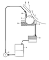
- FIG. 2 is a schematic diagram illustrating the configuration of the cleaning device 12 according to the embodiment of the present invention.
- cleaning device 12 includes a cleaning blade 30, a cleaning liquid supply device 32 that supplies a cleaning liquid as a carrier liquid, and a cleaning liquid applied to photoreceptor 2.
- Cleaning roller 34 cleaning liquid tank 36 for storing the cleaning liquid
- recovery device 38 for recovering the cleaning liquid in the cleaning liquid tank 36
- cleaning liquid regeneration for recovering the cleaning liquid recovered by the recovery apparatus 38
- the apparatus 40 includes a spare tank 42 that stores the regenerated cleaning liquid, and a pump 44 that delivers the cleaning liquid stored in the spare tank 42 to the cleaning liquid supply apparatus 32.
- a sponge roller can be used as the cleaning roller 34 as an example.
- An elastic body such as urethane rubber can be used as the cleaning blade 30.
- the above-described IPS 2028 can be used, and silicon oil, white oil, or the like may be used.
- the recovery device 38, the cleaning liquid regenerating device 40, the spare tank 42, and the pump 44 collect the cleaning liquid in the cleaning liquid tank 36, remove the toner particles from the recovered liquid, and remove the purified cleaning liquid.
- a collecting means for sending to the cleaning liquid supply device 32 is configured.
- the above configuration is an example.
- the cleaning liquid in the cleaning liquid tank 36 is collected, and the cleaning liquid purified by removing toner particles from the collected liquid is sent to the cleaning liquid supply device 32 to regenerate the cleaning liquid.
- the spare tank 42 may not be provided, and the functions of the recovery device 38 and the cleaning liquid regenerating device may be executed by one device. Further, as a mechanism for delivering the cleaning liquid, it is possible to adopt a configuration in which the pump 44 is not used when gravity is used.
- the cleaning liquid supply device 32 drops the cleaning liquid at a position upstream of the rotation direction of the cleaning roller 34 (direction f indicated by the arrow) from the position where the cleaning roller 34 is in contact with the photoreceptor 2.
- a part of the cleaning roller 34 is immersed in the cleaning liquid in the cleaning liquid tank 36.
- Rotating the cleaning roller 34 allows the cleaning liquid to be applied to the photoconductor 2 in the contact area with the photoconductor 2. By applying the cleaning liquid in this way, there is an effect that the toner image remaining on the photoreceptor 2 is easily peeled off.
- the toner image remaining on the photoreceptor 2 is scraped off by the cleaning blade 30.
- the cleaning roller 34 contacts the photoconductor 2 when the cleaning liquid is applied to the photoconductor 2, a part of the toner image remaining on the photoconductor 2 adheres to the cleaning roller 34. Become.
- the cleaning roller 34 Since a part of the cleaning roller 34 is immersed in the cleaning liquid tank 36, the toner particles of the toner image remaining during the immersion are redispersed in the cleaning liquid in the cleaning liquid tank 36.
- the toner particles adhering without being redispersed are pumped up by the cleaning roller 34, but are washed away by the cleaning liquid supplied from the cleaning liquid supply device 32. Then, the cleaning liquid purified as described above is applied to the photoreceptor 2 by the cleaning roller 34.
- the concentration of the toner particles in the cleaning liquid tank 36 may increase.
- the toner particle concentration at the cleaning blade 30 is 30 wt% or less, there is no influence on the next image, but when it exceeds, a cleaning failure occurs.
- the liquid amount of the cleaning liquid in the cleaning liquid tank 36 is 500 cc, the image is formed on the cleaning blade 30 when image formation is performed on about 8000 sheets. The toner particle concentration exceeded 30 wt%, resulting in poor cleaning.
- the cleaning liquid in the cleaning liquid tank 36 is recovered using the recovery device 38. Then, the recovered cleaning liquid is sent to the cleaning liquid regenerating device 40.
- the cleaning liquid regenerator 40 separates the toner particles and the carrier liquid by mechanical filtration such as a filter. Then, the treatment is purified to a carrier liquid from which the toner particles are removed. Then, the cleaning liquid that is the purified carrier liquid is sent to the reserve tank 42. The cleaning liquid is circulated from the reserve tank 42 to the cleaning liquid supply device 32 via the pump 44.
- This configuration suppresses the toner particle concentration in the cleaning liquid tank 36 from becoming too high. That is, since the cleaning liquid in a desired state can always be applied to the photoreceptor 2, the number of toner particles that pass through the cleaning blade 30 can be suppressed to prevent the occurrence of defective cleaning. That is, it is possible to ensure good cleaning properties. Further, since the cleaning liquid is circulated, the amount of waste liquid can be reduced to reduce the cost.
- the amount of cleaning liquid recovered by the recovery device 38 and the amount of cleaning liquid supplied from the cleaning liquid supply device 32 can be made equal to each other so that the cleaning liquid amount in the cleaning liquid tank 36 can be made constant. It is.
- a recovery device 38 is provided on the downstream side of the rotation direction of the cleaning roller 34 (direction f indicated by an arrow) with respect to the position where the cleaning roller 34 contacts the photoconductor 2 as a reference.
- the recovery device 38 is located further upstream in the rotational direction of the cleaning roller 34 at the subsequent rotational position of the cleaning roller 34.
- the cleaning liquid supply device 32 is provided on the downstream side.
- the recovery device 38 is disposed at a position close to the position where the toner particles of the remaining toner image adhering to the cleaning roller 34 are dispersed in the cleaning liquid tank 36, and the toner can be efficiently used. It becomes possible to collect a cleaning liquid having a high particle concentration.
- the cleaning roller 34 may be dropped into the cleaning liquid tank 36 on the upstream side in the rotation direction (direction f indicated by an arrow). In other words, starting from the position where the cleaning roller 34 comes into contact with the photosensitive member 2, the cleaning roller 34 is dropped into the cleaning liquid tank 36 on the downstream side of the recovery device 38 at the subsequent rotation position of the cleaning roller 34.
- the cleaning liquid when the cleaning liquid is dropped onto the cleaning roller 34, it may be performed via a separate member as will be described in Modification 1 described later.
- the method of supplying the cleaning liquid to the cleaning liquid tank is not limited to dropping, and may be a method of directly injecting the cleaning liquid into the cleaning liquid tank through the flow path.
- the cleaning liquid regenerating apparatus 40 may employ other methods, for example, a method in which toner particles are attached to the electrodes by an electric field to separate the toner particles from the carrier liquid. good.
- the liquid developer that is a residual toner image scraped off by the cleaning blade 30 is dropped into the cleaning liquid tank 36 and redispersed.
- the liquid developer is stored in another storage tank. May be.
- it is possible to adopt a configuration in which the storage tank is sent to the cleaning liquid regeneration device 40, or a configuration in which the storage tank is directly sent to the cleaning liquid regeneration device 40 without being stored may be employed.
- the cleaning device of this example has been described as being provided on the photoconductor 2, it is not limited to the photoconductor, and may be provided on an intermediate transfer body. Moreover, you may make it apply to the cleaning apparatus provided in a developing device.
- the cleaning roller 34 uses a sponge roller
- the cleaning roller 34 is not limited to the sponge roller, and an elastic member such as rubber or a brush may be used.
- an elastic member such as rubber or a brush
- a metal roller may be used.
- a configuration may be adopted in which a regulating member is newly provided in the cleaning roller 34 at a position from when the cleaning liquid is supplied until the cleaning roller 34 comes into contact with the photosensitive member 2 to regulate the amount of the cleaning liquid.
- the cleaning roller 34 and the photoreceptor 2 have been described so as to rotate so as to move in opposite directions at the contact position.
- the cleaning roller 34 is rotated so as to move in the same direction. May be.
- the recovery device is located upstream of the rotation direction of the cleaning roller 34 in the rotation position after the contact. 38 may be arranged so that the cleaning liquid is supplied at a position downstream of the recovery device 38.
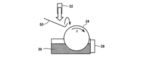
- FIG. 3 is a diagram illustrating the configuration of the cleaning device according to the first modification of the embodiment of the present invention.
- a cleaning liquid supply device 32 mainly, a cleaning roller 34, a cleaning liquid tank 36, and a recovery device 38 are shown.
- Other configurations of the cleaning blade 30, the cleaning liquid regenerating device 40, the spare tank 42, the pump 44, and the like are the same as those described with reference to FIG. 2, and thus detailed description thereof will not be repeated.
- FIG. 2 is different from the configuration of FIG. 2 in that the leveling member 50 is further provided in the configuration according to the first modification.
- the leveling member 50 is disposed between the cleaning liquid supply device 32 and the cleaning roller 34.
- the cleaning liquid dropped from the cleaning liquid supply device 32 is uniformly leveled by the leveling member 50 in the longitudinal direction.
- the cleaning roller 34 is formed in a cylindrical shape, and the cleaning liquid is dropped onto the circumferential region in the longitudinal direction.
- the leveling member 50 is provided along the longitudinal direction in the same manner as the cleaning roller 34, and is provided with a concave portion such as a bend.
- the cleaning liquid dropped on the leveling member 50 from the cleaning liquid supply device 32 is provided in the recess so as to overflow from the recess and drop onto the cleaning roller 34 when a predetermined amount or more is accumulated.
- the cleaning liquid dropped from the cleaning liquid supply device 32 is uniformly supplied to the circumferential region in the longitudinal direction with respect to the cleaning roller 34 via the leveling member 50.
- the cleaning liquid is dripped from the cleaning liquid supply device 32 to a partial region in the longitudinal direction of the cleaning roller 34, but with the configuration according to the first modification, the circumference of the cleaning roller 34 in the longitudinal direction is reduced.
- FIG. 4 is a diagram illustrating the configuration of the cleaning device according to the second modification of the embodiment of the present invention.
- a cleaning liquid supply device 32 mainly, a cleaning roller 34, a cleaning liquid tank 36, and a recovery device 38 are shown. Further, the photoconductor 2 and the cleaning blade 30 in contact with the photoconductor 2 are shown. Other configurations of the cleaning liquid regenerating apparatus 40, the spare tank 42, the pump 44, and the like are the same as those described with reference to FIG.
- FIG. 2 is different from the configuration of FIG. 2 in that the screw 52 is further provided in the cleaning liquid tank 36 in the configuration according to the second modification. It is assumed that the screw 52 rotates in the cleaning liquid tank 36 so that the flow direction of the cleaning liquid is a direction toward the recovery device 38 (direction g indicated by an arrow).
- the cleaning liquid flow in the cleaning liquid tank 36 is formed in accordance with the rotation direction of the cleaning roller 34 (direction f indicated by the arrow). Is done. That is, the cleaning liquid acts to flow in the direction opposite to the direction g indicated by the arrow according to the rotation of the cleaning roller 34.
- the screw 52 is rotated so that a flow in the direction opposite to the direction of the flow of the cleaning liquid acting according to the rotation of the cleaning roller 34 is formed.
- the cleaning liquid flow is formed in the direction opposite to the direction in which the recovery device 38 is provided by the rotation of the cleaning roller 34.
- a cleaning liquid flow is formed in the direction toward the recovery device 38, so that the recovery device 38 can efficiently recover the cleaning liquid having a high toner particle concentration.
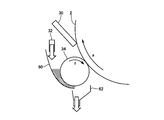
- FIG. 5 is a diagram illustrating the configuration of the cleaning device according to the third modification of the embodiment of the present invention.
- the main difference here is that a cleaning liquid tank 60 is provided instead of the cleaning liquid tank 36.
- a recovery tank 62 is provided at a position where the cleaning liquid drops from the cleaning liquid tank 60 according to gravity instead of the recovery device 38.
- the cleaning liquid flows from the cleaning liquid supply device 32 along the inner wall of the cleaning liquid tank 60.
- the cleaning liquid collected between the inner wall of the cleaning liquid tank 60 and the cleaning roller 34 is pumped by the cleaning roller 34 and applied to the photoreceptor 2.
- the cleaning liquid tank 60 has a shape in which the cleaning liquid from the cleaning liquid supply device 32 disposed in the upper part flows into the cleaning roller 34 along the shape of the inner wall. It is configured to drop from the cleaning liquid tank 60. It is assumed that the cleaning liquid dropped from the cleaning liquid tank 60 is sent to the above-described cleaning liquid regenerator 40 through the collection tank 62 (not shown). Since other configurations are the same as those described with reference to FIG. 2, detailed description thereof will not be repeated.
- the cleaning liquid once supplied from the cleaning liquid supply device 32 is finally dropped from the cleaning liquid tank 60 as time elapses, so that the old cleaning liquid and the new cleaning liquid are mixed and the toner is mixed. It is possible to prevent the particles from being deposited. That is, it becomes possible to apply the cleaned cleaning liquid to the photoreceptor 2 constantly, and to ensure good cleaning properties. Further, since the cleaning liquid is recovered using gravity, a simple configuration can be provided without providing the recovery device 38.
- the cleaning liquid tank 60 and the collection tank 62 are illustrated as separate members, the shape is not limited to the particular shape, and it is possible to form a single body.
- the inner wall of the cleaning liquid tank 60 has been described as having a curvature shape, the inner wall is not particularly limited to this, and may be a straight line, or the shape is not limited thereto. Even in the case of the configuration of the cleaning liquid tank 36, a configuration may be adopted in which a discharge port is provided at the lowermost portion and the cleaning liquid is discharged therefrom.
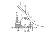
- FIG. 6 is a diagram illustrating the configuration of the cleaning device according to the fourth modification of the embodiment of the present invention.
- a cleaning liquid supply device 32 mainly, a cleaning roller 34, a cleaning liquid tank 36, and a recovery device 38 are shown. Further, the photoconductor 2 and the cleaning blade 30 in contact with the photoconductor 2 are shown. Moreover, the case where the partition plate 70 is provided in the cleaning liquid tank 36 is shown.
- Other configurations of the cleaning liquid regenerating apparatus 40, the spare tank 42, the pump 44, and the like are the same as those described with reference to FIG. 2, and thus detailed description thereof will not be repeated.
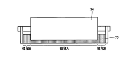
- FIG. 7 is a view for explaining the relationship between the partition plate 70 and the cleaning roller 34 according to the fourth modification of the embodiment of the present invention.
- partition plate 70 and cleaning roller 34 as seen from the front (longitudinal direction) is shown.
- the partition plate 70 and the cleaning roller 34 are in contact with each other.
- the partition plate 70 has two regions with different end heights. Specifically, it has the area
- the partition plate 70 By providing the partition plate 70 in the cleaning liquid tank 36, the partition plate 70 separates it into two cleaning liquid regions.
- the first position which is the downstream side of the partition plate 70 in the rotational position of the cleaning roller 34 after the contact.
- the region A of the partition plate 70 and the cleaning roller 34 come into contact with each other, so that the toner particles attached to the cleaning roller 34 are mechanically separated. Then, in the first region 36 a of the cleaning liquid tank 36, the cleaning liquid supplied from the cleaning liquid supply device 32 is pumped up and applied to the photoreceptor 2.
- the region B of the partition plate 70 is set higher than the region A so that the cleaning liquid does not flow into the first region 36a from the second region 36b. Further, it is desirable that the first region 36a does not flow into the second region 36b.
- the partition plate 70 serves to prevent toner particles from entering the first region 36a from the second region 36b and to keep the cleaning liquid in the first region 36a cleaner.
- the cleaning liquid may be allowed to flow from the first region 36a to the second region 36b, but it is prevented from flowing from the second region 36b to the first region 36a. Is desirable.
- the configuration in which the partition plate 70 is provided and the cleaning liquid tank 36 is separated into the first region 36a and the second region 36b has been described.
- the cleaning roller 34 is used as the partition plate to perform the first operation.
- the region 36a and the second region 36b may be separated.
- the cleaning roller 34 immersed in the cleaning liquid tank 36 is in contact with the lowermost area of the cleaning liquid tank 36 to form the first area 36a and the second area 36b,
Landscapes
- Physics & Mathematics (AREA)
- General Physics & Mathematics (AREA)
- Cleaning In Electrography (AREA)
- Wet Developing In Electrophotography (AREA)
Abstract
クリーニングブレードと、キャリア液であるクリーニング液を供給するクリーニング液供給部と、クリーニング液を感光体に塗布するためのクリーニングローラーと、塗布した後の余剰のクリーニング液を回収するための回収手段とを備え、回収手段は、回収したクリーニング液を再生して、再生されたクリーニング液をクリーニング液供給部に送出する。
Description
本発明は、電子写真方式の画像形成装置に関し、キャリア液中にトナーを分散させてなる液体現像剤を用いて画像形成を行なう湿式の画像形成装置に関する。
電子写真方式の画像形成装置においては、感光体上に形成された静電潜像がトナーにより現像されて、そのトナー像が記録用紙に転写されて、画像が形成される。また、中間転写体を備えている場合は、トナー像が、一旦、感光体から中間転写体へ一次転写されて、さらに中間転写体から記録用紙へ二次転写されて、画像が形成されることになる。このような画像形成装置の転写プロセスでは、一般に静電転写方式が採用されている。
たとえば、感光体上のトナー像を被転写体である中間転写体へ一次転写する場合は、感光体と対向するように配置された中間転写体に電圧を印加し、感光体と中間転写体との間に電界を形成してこの電界によりトナー像を中間転写体に静電吸着させている。
また、中間転写体のトナー像を被転写体である用紙へ転写する場合は、中間転写体と対向するように配置された用紙の裏面から転写ローラー等により電圧を印加し、中間転写体と用紙との間に電界を形成してこの電界によりトナー像を用紙に静電吸着させている。
このような転写プロセスにおいて、電界に乱れが生じたり、トナーの感光体あるいは中間転写体への付着力が強過ぎたりすると一部のトナーが転写されずに感光体あるいは中間転写体上に残留し、転写効率が低下することになる。
したがって、残留したトナーを転写の都度充分にクリーニングする必要がある。
特開2002-132106号公報においては、クリーニングブレードとクリーニングローラーとを設けて、クリーニングローラーによりクリーニング液を十分に供給することにより残留したトナーが乾燥して凝固することを防止して、クリーニング不良が生じるのを抑制する方式が開示されている。
特開2002-132106号公報においては、クリーニングブレードとクリーニングローラーとを設けて、クリーニングローラーによりクリーニング液を十分に供給することにより残留したトナーが乾燥して凝固することを防止して、クリーニング不良が生じるのを抑制する方式が開示されている。
特開2002-132106号公報においては、クリーニング液に浸漬されたクリーニングローラーから感光体にクリーニング液を塗布する構成が示されているが、クリーニング液に塗布する際にクリーニングローラー側にもトナーが付着するため繰り返し使用する場合には、クリーニング液に含まれるトナー粒子の濃度が高くなる可能性がある。
クリーニング液に含まれるトナー粒子の濃度が高くなると、クリーニングブレードをすり抜けるトナー粒子の数が増加するためクリーニング不良となる可能性がある。
本発明は、上記のような問題を解決するためになされたものであって、クリーニング液に含まれるトナー粒子の濃度を抑制することで、良好なクリーニング性を確保することが可能な湿式画像形成装置を提供することを目的とする。
本発明のある局面に従う湿式画像形成装置は、キャリア液にトナーが分散された液体現像剤を用いて像担持体上にトナー像を形成する湿式画像形成装置であって、像担持体上のトナー像を除去するためのクリーニングブレードと、像担持体の回転方向においてクリーニングブレードより上流側に設けられ、像担持体に対してクリーニング液を塗布するクリーニングローラーと、クリーニングローラーに対してクリーニング液を供給するクリーニング液供給部と、クリーニングローラーが像担持体にクリーニング液を塗布した後の、トナー粒子を含む余剰のクリーニング液を回収する回収手段と、を備える。回収手段は、回収したクリーニング液からトナー粒子を除去して浄化したクリーニング液をクリーニング液供給部に送出する。
好ましくは、クリーニングローラーが像担持体と接触した後の回転位置において、クリーニングローラーの回転方向の上流側の位置にて回収手段がクリーニング液を回収し、該回収位置より下流側にクリーニング液供給部が設けられる。
好ましくは、クリーニングローラーを覆うようにして、クリーニングローラーから滴下したトナー粒子を含む余剰のクリーニング液を貯留するクリーニング液貯留槽をさらに備え、クリーニングローラーが像担持体と接触した後の回転位置において、クリーニングローラーがクリーニング液貯留槽に貯留されたクリーニング液に浸漬される。
特に、クリーニング液貯留槽にクリーニングローラーの回転方向に従ってクリーニング液貯留槽に生じるクリーニング液の流れの方向に対して反対方向の流れを形成するためのスクリューをさらに備える。
特に、クリーニング液供給部は、クリーニング液貯留槽にクリーニング液を供給する。
特に、クリーニング液貯留槽は、クリーニングローラーとクリーニング液貯留槽とで囲まれた第1のクリーニング液槽と、クリーニングローラーとクリーニング液貯留槽とで囲まれた第2のクリーニング液槽とに分離される。
特に、クリーニング液貯留槽は、クリーニングローラーとクリーニング液貯留槽とで囲まれた第1のクリーニング液槽と、クリーニングローラーとクリーニング液貯留槽とで囲まれた第2のクリーニング液槽とに分離される。
特に、クリーニング液供給部は、第1のクリーニング液槽にクリーニング液を供給し、回収手段は、第2のクリーニング液槽からトナー粒子を含む余剰のクリーニング液を回収する。
特に、クリーニング液貯留槽は、クリーニングローラーと当接して第1のクリーニング液槽と第2のクリーニング液槽とを分離するために設けられた仕切り板を含む。
特に、仕切り板は、先端がクリーニングローラーに当接する第1の領域と、先端が第1の領域の高さよりも高い第2の領域とを有する。
好ましくは、クリーニング液供給部は、クリーニング液をクリーニングローラー表面に直接滴下するようにして供給する。
本発明のある局面に従う湿式画像形成装置は、像担持体に対してクリーニング液を塗布するクリーニングローラーと、クリーニングローラーに対してクリーニング液を供給するクリーニング液供給部と、クリーニングローラーが像担持体に塗布した後のトナー粒子を含む余剰のクリーニング液を回収する回収手段とを備える。回収手段は、回収した液からトナー粒子を除去して浄化したクリーニング液をクリーニング液供給部に送出する。したがって、クリーニングローラーには浄化したクリーニング液が供給されるため、クリーニング液に含まれるトナー粒子の濃度を抑制して、良好なクリーニング性を確保することができる。
以下、本発明の実施の形態について、図面を参照して説明する。以下の説明では、同一の部品には同一の符号を附してある。それらの名称および機能も同じである。したがって、それらについての詳細な説明は繰返さない。
本発明の実施の形態においては、画像形成装置の一例として湿式画像形成装置について代表的に説明する。
図1は、本発明の実施の形態に従う湿式画像形成装置の一例を示す概略構成図である。
図1を参照して、本発明の実施の形態1に従う湿式画像形成装置には、ドラム状の像担持体である感光体2が設けられ、感光体2の周辺には矢印で示す回転方向aの順に現像装置の現像ローラー18、加圧ローラー10、クリーニング装置12、イレーサランプ14、帯電装置4および露光装置6がそれぞれ配設される。
図1を参照して、本発明の実施の形態1に従う湿式画像形成装置には、ドラム状の像担持体である感光体2が設けられ、感光体2の周辺には矢印で示す回転方向aの順に現像装置の現像ローラー18、加圧ローラー10、クリーニング装置12、イレーサランプ14、帯電装置4および露光装置6がそれぞれ配設される。
感光体2の表面は、帯電装置4により所定の表面電位に一様に帯電される。そして、その後、露光装置6により画像情報の露光を行ない、感光体2の表面に静電潜像を形成する。次いで、感光体2上の静電潜像は、現像装置の現像ローラー18によりキャリア液中にトナー粒子を分散させた液体現像剤で現像され、感光体2の表面にトナー像が形成される。このとき、トナー粒子だけでなくキャリア液も感光体2の表面に付着する。
そして、感光体2の表面に形成されたトナー像は、加圧ローラー10との対向部である転写部に運ばれる。そして、転写部では、被転写体である記録用紙Pが矢印の方向eに搬送され、加圧ローラー10に印加されたトナー粒子と逆極性の電圧の力により感光体2上のトナー粒子は被転写体である記録用紙Pに転写される。そして、トナー粒子が転写された記録用紙Pは、図示しない定着部に搬送されトナー像が定着される。
一方、感光体2において、回転により転写部を通過した後の位置には、上述したクリーニング装置12が設けられており、感光体2上に残留したトナー像(液体現像剤)を回収する。クリーニング装置12によりクリーニングされた感光体2はイレーサランプ14により露光され、潜像電位がキャンセルされる。以上の工程を繰り返し行なうことにより、次々に画像が印字される。
ここで、液体現像剤は、キャリア液である絶縁性液体と、静電潜像を現像するトナー粒子と、トナー粒子を分散させる分散剤とを主要成分としている。
キャリア液としては、一般に電子写真用液体現像剤に用いるものであれば特に制限することなく使用することができるが、中でも不揮発性の液体は好ましい。不揮発性液体としてはたとえば、シリコンオイル、ミネラルオイル、パラフィンオイル、鉱物油等を挙げることができる。
トナー粒子としては、一般に電子写真用液体現像剤に用いるものであれば、特に制限することなく使用することができる。トナー用結着樹脂としては、たとえばポリスチレン樹脂、スチレンアクリル樹脂、アクリル樹脂、ポリエステル樹脂、エポキシ樹脂、ポリアミド樹脂、ポリイミド樹脂、ポリウレタン樹脂等の熱可塑性樹脂を用いることができる。またこれらの樹脂を複数、混合して用いることも可能である。また、トナーの着色に用いられる顔料および染料も一般に市販されているものを用いることができる。たとえば、顔料としては、カーボンブラック、ベンガラ、酸化チタン、シリカ、フタロシアニンブルー、フタロシアニングリーン、スカイブルー、ベンジジンイエロー、レーキレッドD等を用いることができる。染料としてはソルベントレッド27やアシッドブルー9等を用いることができる。
液体現像剤の調製方法としては、一般に用いられる技法に基づいて調製することができる。たとえば、結着剤樹脂と顔料とを所定の配合比で、加圧ニーダ、ローラーミルなどを用いて溶融混練して均一に分散させ、得られた分散体をたとえばジェットミルによって微粉砕する。得られた微粉末をたとえば風力分級機などにより分級することで、所望の粒径の着色トナーを得ることができる。そして、得られたトナー粒子をキャリア液としての絶縁性液体と所定の配合比で混合する。この混合物をボールミル等の分散手段により均一に分散させ、液体現像剤を得ることができる。
なお、本例においては、一例としてポリエステル樹脂を100部、銅フタロシアニン15部をヘンシェルミキサーで十分混合した後、ロール内加熱温度100℃の同方向回転二軸押出し機を用い溶融混練を行い、得られた混合物を冷却、粗粉砕して粗粉砕トナーを得た。また、IPS2028(出光興産社製)75部、粗粉砕トナーを25部、分散剤としてV216(IPS社製)を0.8部混合し、サンドミルにより4日間湿式粉砕し、湿式現像剤を得た。なお、その時の粒径は2.0μmであった。粒径はレーザ回折式粒度分布測定装置(SALD-2200(島津製作所社製))にて測定した。
次に、現像装置の構成について説明する。
現像装置には、感光体2と加圧接触される現像ローラー18と、キャリア液中に分散させたトナー粒子を含む液体現像剤を貯蔵した現像槽28と、現像槽28に一部が浸漬され、液体現像剤を汲み上げる汲み上げローラー24と、汲み上げローラー24により汲み上げられた液体現像剤の厚みを規制して計量する規制部材26と、汲み上げローラー24により汲み上げられた液体現像剤を現像ローラー18に供給する供給ローラー22とを含む。供給ローラー22と互いに隣接している汲み上げローラー24は矢印で示す方向dに回転する。また、供給ローラー22は汲み上げローラー24との接触領域において同一方向(矢印で示す方向c)に回転するものとする。また、汲み上げローラー24は、供給ローラー22に従動して回転するものとする。また、現像ローラー18は、供給ローラー22との接触領域において供給ローラー22の回転方向cと反対方向bに回転するものとする。反対方向とすることにより供給ローラー22から現像ローラー18への液体現像剤を効率的に供給することが可能となる。また、現像ローラー18の薄層を均一にすることが可能である。
現像装置には、感光体2と加圧接触される現像ローラー18と、キャリア液中に分散させたトナー粒子を含む液体現像剤を貯蔵した現像槽28と、現像槽28に一部が浸漬され、液体現像剤を汲み上げる汲み上げローラー24と、汲み上げローラー24により汲み上げられた液体現像剤の厚みを規制して計量する規制部材26と、汲み上げローラー24により汲み上げられた液体現像剤を現像ローラー18に供給する供給ローラー22とを含む。供給ローラー22と互いに隣接している汲み上げローラー24は矢印で示す方向dに回転する。また、供給ローラー22は汲み上げローラー24との接触領域において同一方向(矢印で示す方向c)に回転するものとする。また、汲み上げローラー24は、供給ローラー22に従動して回転するものとする。また、現像ローラー18は、供給ローラー22との接触領域において供給ローラー22の回転方向cと反対方向bに回転するものとする。反対方向とすることにより供給ローラー22から現像ローラー18への液体現像剤を効率的に供給することが可能となる。また、現像ローラー18の薄層を均一にすることが可能である。
なお、本例においては、供給ローラー22と現像ローラー18とにそれぞれを回転させるための駆動機構が設けられており、汲み上げローラー24には回転させるための駆動機構は設けられていないものとする。
なお、汲み上げローラー24には表面に凹部を設けた金属ローラー(アニロックスローラー)を用いることで液体現像剤の量を正確に規制するようにしても良い。
現像ローラー18の周辺には帯電装置16が設けられるとともに、クリーニングブレード20が設けられる。そして、現像ローラー18には、上述したように所定量の液体現像剤が供給され、帯電装置16により現像ローラー18上の液体現像剤中に含まれるトナー粒子に電荷が与えられる。その後、現像ローラー18により感光体2に搬送された荷電されたトナー粒子は感光体2上において画像部を現像する。
各ローラー等は、円柱状であり、本例では、その断面部分が示されている。
図2は、本発明の実施の形態に従うクリーニング装置12の構成を説明する概略図である。
図2は、本発明の実施の形態に従うクリーニング装置12の構成を説明する概略図である。
図2を参照して、本発明の実施の形態に従うクリーニング装置12は、クリーニングブレード30と、キャリア液であるクリーニング液を供給するクリーニング液供給装置32と、クリーニング液を感光体2に塗布するためのクリーニングローラー34と、クリーニング液を貯留するクリーニング液槽36と、クリーニング液槽36のクリーニング液を回収するための回収装置38と、回収装置38で回収したクリーニング液を再生するためのクリーニング液再生装置40と、再生されたクリーニング液を貯蔵する予備タンク42と、予備タンク42に貯蔵されたクリーニング液をクリーニング液供給装置32に送出するポンプ44とを含む。
なお、本例においては、一例としてクリーニングローラー34として、スポンジローラーを用いることが可能である。クリーニングブレード30として、ウレタンゴム等の弾性体を用いることが可能である。
クリーニング液は、上述したIPS2028を用いることが可能であり、シリコンオイルやホワイトオイル等を用いるようにしても良い。
本例においては、回収装置38、クリーニング液再生装置40、予備タンク42、ポンプ44は、クリーニング液槽36のクリーニング液を回収して、回収した液からトナー粒子を除去して浄化したクリーニング液をクリーニング液供給装置32に送出する回収手段を構成する。なお、上記構成は、一例であり、クリーニング液槽36のクリーニング液を回収して、回収した液からトナー粒子を除去して浄化したクリーニング液をクリーニング液供給装置32に送出してクリーニング液を再生できる構成であればどのような構成でも良い。例えば、予備タンク42を設けない構成とすることも可能であるし、回収装置38およびクリーニング液再生装置のそれぞれの機能を1つの装置で実行するようにしても良い。また、クリーニング液を送出する機構として、重力を利用する場合にはポンプ44を用いない構成とすることも可能である。
クリーニング装置12の動作について説明する。
クリーニング液供給装置32は、クリーニングローラー34が感光体2と接触する位置を基準とし、その位置よりクリーニングローラー34の回転方向(矢印で示す方向f)の上流側の位置にクリーニング液を滴下する。
クリーニング液供給装置32は、クリーニングローラー34が感光体2と接触する位置を基準とし、その位置よりクリーニングローラー34の回転方向(矢印で示す方向f)の上流側の位置にクリーニング液を滴下する。
また、本例においては、クリーニングローラー34の一部は、クリーニング液槽36のクリーニング液に浸漬している。
当該クリーニングローラー34を回転させることにより感光体2との接触領域においてクリーニング液を感光体2に塗布することが可能となる。このようにクリーニング液を塗布することにより、感光体2上に残留したトナー像がはがれやすくなるという効果がある。
そして、クリーニングブレード30において感光体2に残留したトナー像を掻き取る。
ところで、上記のようにクリーニングローラー34が感光体2にクリーニング液を塗布する際に感光体2と接触することにより、感光体2の残留したトナー像の一部がクリーニングローラー34に付着することになる。
ところで、上記のようにクリーニングローラー34が感光体2にクリーニング液を塗布する際に感光体2と接触することにより、感光体2の残留したトナー像の一部がクリーニングローラー34に付着することになる。
クリーニングローラー34の一部は、クリーニング液槽36に浸漬しているため、浸漬中に残留したトナー像のトナー粒子がクリーニング液槽36でクリーニング液中で再分散される。再分散せずに付着したトナー粒子は、クリーニングローラー34により汲み上げられるがクリーニング液供給装置32から供給されるクリーニング液により洗い流される。そして、上述したように浄化されたクリーニング液がクリーニングローラー34によって感光体2に塗布される。
一方で、トナー像のトナー粒子がクリーニング液槽36のクリーニング液中で再分散されるためクリーニング液槽36のトナー粒子の濃度が増加する可能性がある。クリーニングブレード30でのトナー粒子の濃度が30wt%以下の場合には、次の画像に影響はないが、越える場合にはクリーニング不良が発生する。具体的には、クリーニング液を再生する機構を持たない構成では、クリーニング液槽36のクリーニング液の液量が500ccの場合、約8000枚に対して画像形成を実行した場合にクリーニングブレード30でのトナー粒子の濃度が30wt%を越えてクリーニング不良が発生した。
本例においては、回収装置38を用いてクリーニング液槽36のクリーニング液を回収する。そして、回収したクリーニング液をクリーニング液再生装置40に送る。クリーニング液再生装置40は、フィルタ等の機械的な濾過によりトナー粒子とキャリア液とを分離する。そして、当該処理により、トナー粒子を除去したキャリア液に浄化される。そして、浄化したキャリア液であるクリーニング液を予備タンク42に送る。予備タンク42からポンプ44を介してクリーニング液供給装置32に送出して、クリーニング液を循環させる。
当該構成により、クリーニング液槽36のトナー粒子の濃度が高くなりすぎることを抑制する。すなわち、常に望ましい状態のクリーニング液を感光体2に塗布できるため、クリーニングブレード30をすり抜けるトナー粒子の数を抑制してクリーニング不良が生じるのを防止できる。つまり、良好なクリーニング性を確保することが可能である。さらに、クリーニング液を循環させるため廃棄液量を削減してコストを低下させることも可能である。
また、回収装置38で回収するクリーニング液の液量とクリーニング液供給装置32から供給するクリーニング液の液量とを同量とすることによりクリーニング液槽36のクリーニング液量を一定にすることが可能である。
また、クリーニング液槽36において、クリーニングローラー34が感光体2と接触する位置を基準とし、その位置よりクリーニングローラー34の回転方向(矢印で示す方向f)の下流側に回収装置38を設ける。換言すると、クリーニングローラー34が感光体2と接触する位置を起点とした場合には、それより後のクリーニングローラー34の回転位置において、クリーニングローラー34の回転方向の、より上流側に回収装置38が設けられ、その下流側にクリーニング液供給装置32が設けられることになる。当該位置に配置することにより、クリーニング液槽36において、クリーニングローラー34に付着した残留したトナー像のトナー粒子が分散される位置と近い位置に回収装置38を配置することになり、効率的にトナー粒子の濃度の高いクリーニング液を回収することが可能となる。
なお、本例においては、クリーニング液をクリーニングローラー34に直接滴下する構成について説明したが、特にこれに限られず、直接滴下しなくても、クリーニングローラー34と感光体2とが接触する位置を基準としてクリーニングローラー34の回転方向(矢印で示す方向f)の上流側のクリーニング液槽36に滴下する構成としても良い。換言すると、クリーニングローラー34が感光体2と接触する位置を起点とすると、それより後のクリーニングローラー34の回転位置において、回収装置38よりも下流側のクリーニング液槽36に滴下することになる。
また、クリーニング液をクリーニングローラー34に滴下する際、後述の変形例1で説明するように別部材を介して行っても良い。さらに、クリーニング液をクリーニング液槽に供給する方法としては滴下に限られず、流路を通じて直接クリーニング液槽に注入するなどの方法であっても良い。
また、クリーニング液再生装置40は、機械的な濾過以外にも他の方式、例えば、電界によりトナー粒子を電極に付着させて、トナー粒子とキャリア液とを分離させる方式を採用するようにしても良い。
また、本構成においては、クリーニングブレード30で掻き取った残留したトナー像である液体現像剤は、クリーニング液槽36に滴下し、再分散されるものとするが、例えば、別の貯留槽に貯めても良い。また、当該貯留槽からクリーニング液再生装置40に送られる構成とすることも可能であるし、あるいは、貯留することなく、直接、クリーニング液再生装置40に送られる構成を採用しても良い。
また、本例のクリーニング装置については、感光体2に対して設けた構成として説明したが、特に感光体に限られず中間転写体に設ける構成であっても良い。また、現像装置に設けられるクリーニング装置に適用するようにしてもよい。
また、クリーニングローラー34は、スポンジローラーを用いる場合について説明したが、スポンジローラーに限られず、ゴム等の弾性部材やブラシを用いるようにしても良い。また、感光体が弾性体やフィルム状の構成の場合には、金属製のローラーを用いるようにしても良い。
また、クリーニングローラー34において、クリーニング液が供給されてから、クリーニングローラー34が感光体2と接触するまでの位置に規制部材を新たに設けて、クリーニング液の液量を規制する構成としても良い。
また、本構成においては、クリーニングローラー34と感光体2とが、その接触位置において互いに反対方向に移動するように回転する構成について説明したが、同一方向に移動するようにクリーニングローラー34を回転させても良い。その場合であってもクリーニング液槽36において、クリーニングローラー34と感光体2とが接触する位置を起点とすると、接触した後の回転位置において、クリーニングローラー34の回転方向のより上流側に回収装置38を配置し、回収装置38より下流側の位置でクリーニング液を供給するような構成とすればよい。
(変形例1)
図3は、本発明の実施の形態の変形例1に従うクリーニング装置の構成を説明する図である。
図3は、本発明の実施の形態の変形例1に従うクリーニング装置の構成を説明する図である。
図3を参照して、ここでは、主に、クリーニング液供給装置32、クリーニングローラー34、クリーニング液槽36および回収装置38が示されている。その他のクリーニングブレード30、クリーニング液再生装置40、予備タンク42およびポンプ44等の構成については図2で説明したのと同様であるのでその詳細な説明は繰り返さない。
図2の構成と比較して、本変形例1に従う構成においては、均し部材50をさらに設けた点が異なる。
均し部材50は、クリーニング液供給装置32とクリーニングローラー34との間に配置される。クリーニング液供給装置32から滴下されたクリーニング液は均し部材50で均一に長手方向に均される。上述したようにクリーニングローラー34は、円柱状に形成されており、その長手方向の円周領域にクリーニング液が滴下される。
均し部材50は、クリーニングローラー34と同様に長手方向に沿って設けられるとともに、曲げ等の凹み部が設けられている。均し部材50にクリーニング液供給装置32から滴下されたクリーニング液は、当該凹み部に溜まり、所定量以上溜まると当該凹み部から溢れてクリーニングローラー34に滴下するように設けられている。
当該構成によりクリーニング液供給装置32から滴下されたクリーニング液は、均し部材50を介してクリーニングローラー34に対して長手方向の円周領域に均一に供給されることになる。
図2の構成においては、クリーニング液供給装置32からクリーニングローラー34の長手方向の一部の領域にクリーニング液が滴下されるが、当該変形例1に従う構成により、クリーニングローラー34の長手方向の円周領域に均一にクリーニング液が供給されることにより当該領域と接触する感光体2に対して均一にクリーニング液を塗布することが可能となり、良好なクリーニング性を確保することが可能である。
(変形例2)
図4は、本発明の実施の形態の変形例2に従うクリーニング装置の構成を説明する図である。
図4は、本発明の実施の形態の変形例2に従うクリーニング装置の構成を説明する図である。
図4を参照して、ここでは、主に、クリーニング液供給装置32、クリーニングローラー34、クリーニング液槽36および回収装置38が示されている。また、感光体2と感光体2に当接されたクリーニングブレード30が示されている。その他のクリーニング液再生装置40、予備タンク42およびポンプ44等の構成については図2で説明したのと同様であるのでその詳細な説明は繰り返さない。
図2の構成と比較して、本変形例2に従う構成においては、クリーニング液槽36内にスクリュー52をさらに設けた点が異なる。スクリュー52は、クリーニング液槽36内においてクリーニング液の流れの方向が回収装置38に向かう方向(矢印で示す方向g)となるように回転するものとする。
図4の構成において、クリーニングローラー34の一部は、クリーニング液槽36に浸漬されているためクリーニングローラー34の回転方向(矢印で示す方向f)に従って、クリーニング液槽36のクリーニング液の流れが形成される。すなわち、クリーニングローラー34の回転に従ってクリーニング液は上記の矢印で示す方向gと反対方向に流れるように作用する。
本変形例2に従う構成においては、クリーニングローラー34の回転に従って作用するクリーニング液の流れの方向と反対方向の流れが形成されるようにスクリュー52を回転させる。
図2の構成においては、クリーニング液槽36において、クリーニングローラー34が回転することにより回収装置38が設けられた方向とは反対方向にクリーニング液の流れが形成されるが、当該構成により、クリーニング液槽36において、スクリュー52を設けることにより、回収装置38に向かう方向にクリーニング液の流れを形成することにより、回収装置38で効率的にトナー粒子の濃度の高いクリーニング液を回収することが可能となる。
(変形例3)
上記の構成においては、クリーニング液槽36を別のクリーニング液槽に変更する構成について説明する。
上記の構成においては、クリーニング液槽36を別のクリーニング液槽に変更する構成について説明する。
図5は、本発明の実施の形態の変形例3に従うクリーニング装置の構成を説明する図である。
図5を参照して、ここでは、主に、クリーニング液槽36の代わりにクリーニング液槽60が設けられている点が異なる。また、回収装置38の代わりにクリーニング液槽60から重力に従ってクリーニング液が滴下する位置に回収槽62が設けられている点が異なる。
当該構成においては、クリーニング液供給装置32からクリーニング液がクリーニング液槽60の内壁に沿って流れ込む。そして、クリーニング液槽60の内壁とクリーニングローラー34との間に溜まったクリーニング液をクリーニングローラー34が汲み上げて、感光体2に塗布する構成となっている。クリーニング液槽60は、上部に配置されたクリーニング液供給装置32からのクリーニング液を内壁の形状に沿ってクリーニングローラー34との間に流し込む形状となっており、流れ込んだクリーニング液は重力にしたがって、クリーニング液槽60から滴下する構成となっている。クリーニング液槽60から滴下したクリーニング液は、回収槽62を介して図示しないが上述のクリーニング液再生装置40に送られるものとする。その他の構成についても図2で説明したのと同様であるのでその詳細な説明は繰り返さない。
当該構成とすることにより、一旦クリーニング液供給装置32から供給されたクリーニング液は、時間の経過に従って最終的にクリーニング液槽60から滴下するため、古いクリーニング液と新しいクリーニング液とが混合されてトナー粒子が堆積することを防止することができる。すなわち、浄化されたクリーニング液を定常的に感光体2に塗布することが可能となり、良好なクリーニング性を確保することが可能である。また、重力を用いてクリーニング液を回収するため回収装置38を設けずに簡易な構成とすることも可能である。
なお、クリーニング液槽60と回収槽62とが別々の部材として図示したが、特に当該形状に限られず、1体成型されたものとすることも可能である。また、クリーニング液槽60の内壁は、曲率形状を有する場合について示したが、特にこれに限られず、直線上であってもよいし、その形状には限定されない。また、クリーニング液槽36のような構成の場合であっても最下部に排出口を設けて、そこからクリーニング液を排出するような構成としても良い。
(変形例4)
図6は、本発明の実施の形態の変形例4に従うクリーニング装置の構成を説明する図である。
図6は、本発明の実施の形態の変形例4に従うクリーニング装置の構成を説明する図である。
図6を参照して、ここでは、主に、クリーニング液供給装置32、クリーニングローラー34、クリーニング液槽36および回収装置38が示されている。また、感光体2と感光体2に当接されたクリーニングブレード30が示されている。また、クリーニング液槽36に仕切り板70が設けられている場合が示されている。その他のクリーニング液再生装置40、予備タンク42およびポンプ44等の構成については図2で説明したのと同様であるのでその詳細な説明は繰り返さない。
図7は、本発明の実施の形態の変形例4に従う仕切り板70とクリーニングローラー34との関係を説明する図である。
図7を参照して、ここでは、仕切り板70とクリーニングローラー34とを正面(長手方向)から見た図が示されている。仕切り板70とクリーニングローラー34とは当接されている。仕切り板70は、端部の高さが異なる2つの領域を有している。具体的には、端部の高さが低い領域Aと、端部の高さが領域Aよりも高い領域Bとを有している。
領域Aと領域Bとの境界となる高さ部分はクリーニングローラー34と当接しているものとする。クリーニング液槽36において、当該仕切り板70を設けることにより、仕切り板70により2つのクリーニング液領域に分離される。図6で示すクリーニング液槽36において、クリーニングローラー34が感光体2と接触する位置を起点とすると、接触した後のクリーニングローラー34の回転位置において、仕切り板70より下流側の領域である第1の領域36a(左側)と、上流側の領域である第2の領域36b(右側)とに分離される。
クリーニング液槽36の第2の領域36bにおいて、仕切り板70の領域Aとクリーニングローラー34とが当接するため、クリーニングローラー34に付着したトナー粒子が機械的に剥離される。そして、クリーニング液槽36の第1の領域36aにおいて、クリーニング液供給装置32から供給されたクリーニング液を汲み上げて感光体2に塗布する。
仕切り板70の領域Bは、クリーニング液が第2の領域36bから第1の領域36aに流れ込まないように領域Aより高くされている。また、第1の領域36aから第2の領域36bにも流れ込まないことが望ましい。
なお、仕切り板70は、第2の領域36bから第1の領域36aにトナー粒子が入ることを防ぎ、第1の領域36aのクリーニング液をよりきれいに保つ役割を果たす。この目的からすれば、第1の領域36aから第2の領域36bにクリーニング液が流れ込むことは許容しても構わないが、第2の領域36bから第1の領域36aに流れ込むことは防止することが望ましい。
当該構成により、第2の領域36bに設けられた回収装置38より効率的にトナー粒子の濃度の高いクリーニング液を回収することが可能となるとともに、第1の領域36aに対してクリーニング液供給装置32からクリーニング液を滴下することによりトナー粒子の濃度の低いクリーニング液を感光体2に塗布して、良好なクリーニング性を確保することが可能である。
なお、本例においては、仕切り板70を設けてクリーニング液槽36を第1の領域36aと第2の領域36bとに分離する構成について説明したが、クリーニングローラー34を仕切り板として用いて第1の領域36aと第2の領域36bとに分離するようにしても良い。具体的には、クリーニング液槽36に浸漬されているクリーニングローラー34をクリーニング液槽36の最下部領域に当接するようにして、第1の領域36aと第2の領域36bとを形成するとともに、クリーニングローラー34の両端がクリーニング液槽36の内側と当接するようにして第1の領域36aから第2の領域36bへの液の移動、また、第2の領域36bから第1の領域36aへの液の移動がないように配置するようにしても良い。当該構成においても同様の効果を期待することができるとともに、仕切り板を設けない構成であるため部品点数を削減することも可能である。
以上、本発明の実施の形態について説明したが、今回開示された実施の形態は全ての点で例示であって制限的なものではないと考えられるべきである。本発明の範囲は請求の範囲によって示され、請求の範囲と均等の意味および範囲内での全ての変更が含まれることが意図される。
2 感光体、4 帯電装置、6 露光装置、10 加圧ローラー、12 クリーニング装置、14 イレーサランプ、16 帯電装置、18 現像ローラー、20,30 クリーニングブレード、22 供給ローラー、24 汲み上げローラー、26 規制部材、28 現像槽、32 クリーニング液供給装置、34 クリーニングローラー、36,60 クリーニング液槽、38 回収装置、40 クリーニング液再生装置、42 予備タンク、44 ポンプ、52 スクリュー、62 回収槽、70 仕切り板。
Claims (10)
- キャリア液にトナーが分散された液体現像剤を用いて像担持体上にトナー像を形成する湿式画像形成装置であって、
前記像担持体上のトナー像を除去するためのクリーニングブレードと、
前記像担持体の回転方向において前記クリーニングブレードより上流側に設けられ、前記像担持体に対してクリーニング液を塗布するクリーニングローラーと、
前記クリーニングローラーに対してクリーニング液を供給するクリーニング液供給部と、
前記クリーニングローラーが前記像担持体にクリーニング液を塗布した後の、トナー粒子を含む余剰のクリーニング液を回収する回収手段と、を備え、
前記回収手段は、回収したクリーニング液からトナー粒子を除去して浄化したクリーニング液を前記クリーニング液供給部に送出する、湿式画像形成装置。 - 前記クリーニングローラーが前記像担持体と接触した後の回転位置において、前記クリーニングローラーの回転方向の上流側の位置にて前記回収手段がクリーニング液を回収し、
該回収位置より下流側に前記クリーニング液供給部が設けられる、請求項1記載の湿式画像形成装置。 - 前記クリーニングローラーを覆うようにして、前記クリーニングローラーから滴下したトナー粒子を含む余剰のクリーニング液を貯留するクリーニング液貯留槽をさらに備え、
前記クリーニングローラーが前記像担持体と接触した後の回転位置において、前記クリーニングローラーが前記クリーニング液貯留槽に貯留されたクリーニング液に浸漬される、請求項1または2記載の湿式画像形成装置。 - 前記クリーニング液貯留槽に前記クリーニングローラーの回転方向に従って前記クリーニング液貯留槽に生じるクリーニング液の流れの方向に対して反対方向の流れを形成するためのスクリューをさらに備える、請求項3記載の湿式画像形成装置。
- 前記クリーニング液供給部は、前記クリーニング液貯留槽にクリーニング液を供給する、請求項3または4記載の湿式画像形成装置。
- 前記クリーニング液貯留槽は、前記クリーニングローラーと前記クリーニング液貯留槽とで囲まれた第1のクリーニング液槽と、前記クリーニングローラーと前記クリーニング液貯留槽とで囲まれた第2のクリーニング液槽とに分離される、請求項3記載の湿式画像形成装置。
- 前記クリーニング液供給部は、前記第1のクリーニング液槽にクリーニング液を供給し、
前記回収手段は、前記第2のクリーニング液槽からトナー粒子を含む余剰のクリーニング液を回収する、請求項6に記載の湿式画像形成装置。 - 前記クリーニング液貯留槽は、前記クリーニングローラーと当接して前記第1のクリーニング液槽と前記第2のクリーニング液槽とを分離するために設けられた仕切り板を含む、請求項6または7に記載の湿式画像形成装置。
- 前記仕切り板は、先端が前記クリーニングローラーに当接する第1の領域と、先端が前記第1の領域の高さよりも高い第2の領域とを有する、請求項8記載の湿式画像形成装置。
- 前記クリーニング液供給部は、クリーニング液を前記クリーニングローラー表面に直接滴下するようにして供給する、請求項1~4、6~9のいずれかに記載の湿式画像形成装置。
Applications Claiming Priority (2)
| Application Number | Priority Date | Filing Date | Title |
|---|---|---|---|
| JP2010179586 | 2010-08-10 | ||
| JP2010-179586 | 2010-08-10 |
Publications (1)
| Publication Number | Publication Date |
|---|---|
| WO2012020608A1 true WO2012020608A1 (ja) | 2012-02-16 |
Family
ID=45567578
Family Applications (1)
| Application Number | Title | Priority Date | Filing Date |
|---|---|---|---|
| PCT/JP2011/064646 Ceased WO2012020608A1 (ja) | 2010-08-10 | 2011-06-27 | 湿式画像形成装置 |
Country Status (1)
| Country | Link |
|---|---|
| WO (1) | WO2012020608A1 (ja) |
Citations (4)
| Publication number | Priority date | Publication date | Assignee | Title |
|---|---|---|---|---|
| JPH04270370A (ja) * | 1991-02-26 | 1992-09-25 | Ricoh Co Ltd | 湿式クリーニング装置 |
| JPH06102770A (ja) * | 1992-09-22 | 1994-04-15 | Ricoh Co Ltd | 転写ベルト搬送装置 |
| JPH10268645A (ja) * | 1997-03-25 | 1998-10-09 | Minolta Co Ltd | 現像剤補給装置 |
| JPH10274910A (ja) * | 1997-03-31 | 1998-10-13 | Minolta Co Ltd | クリーニング装置 |
-
2011
- 2011-06-27 WO PCT/JP2011/064646 patent/WO2012020608A1/ja not_active Ceased
Patent Citations (4)
| Publication number | Priority date | Publication date | Assignee | Title |
|---|---|---|---|---|
| JPH04270370A (ja) * | 1991-02-26 | 1992-09-25 | Ricoh Co Ltd | 湿式クリーニング装置 |
| JPH06102770A (ja) * | 1992-09-22 | 1994-04-15 | Ricoh Co Ltd | 転写ベルト搬送装置 |
| JPH10268645A (ja) * | 1997-03-25 | 1998-10-09 | Minolta Co Ltd | 現像剤補給装置 |
| JPH10274910A (ja) * | 1997-03-31 | 1998-10-13 | Minolta Co Ltd | クリーニング装置 |
Similar Documents
| Publication | Publication Date | Title |
|---|---|---|
| US7590368B2 (en) | Image forming apparatus and method of cleaning intermediate transfer belt | |
| JP2008107787A5 (ja) | ||
| JP2008107787A (ja) | 現像装置及びそれを用いた画像形成装置、並びに、現像方法及びそれを用いた画像形成方法 | |
| JP2008209426A (ja) | クリーニング装置及びこれを備えた画像形成装置 | |
| JP2008170604A (ja) | 液体現像剤を用いる現像装置および現像方法 | |
| JP4816881B2 (ja) | 画像形成装置及び画像形成方法 | |
| WO2012020608A1 (ja) | 湿式画像形成装置 | |
| JP2011209374A (ja) | 画像形成装置 | |
| JP2003345140A (ja) | 画像形成装置 | |
| JP4834414B2 (ja) | クリーニング装置および画像形成装置 | |
| JP2009145411A (ja) | 湿式画像形成装置 | |
| JP2009008726A (ja) | クリーニング装置及び画像形成装置 | |
| JP5145647B2 (ja) | 現像方法、液体現像装置、及び、画像形成装置 | |
| JP4888637B2 (ja) | 画像形成装置および画像形成方法 | |
| JP2007108201A (ja) | 画像形成装置 | |
| JP2007133034A (ja) | 画像形成装置およびプロセスカートリッジ | |
| JP4961142B2 (ja) | 画像形成装置 | |
| JP2006235176A (ja) | 液体現像装置、液体現像方法及び現像ローラのクリーニング方法 | |
| JP4961143B2 (ja) | 画像形成装置 | |
| JP5401963B2 (ja) | クリーニング装置、画像形成装置 | |
| JP2007025185A (ja) | 画像形成装置及び画像形成方法 | |
| JP2009145761A (ja) | 湿式画像形成装置 | |
| JP2009300874A (ja) | 湿式画像形成装置 | |
| JP2008170603A (ja) | 液体現像剤を用いる画像形成方法および画像形成装置 | |
| JP2005338559A (ja) | 画像形成装置 |
Legal Events
| Date | Code | Title | Description |
|---|---|---|---|
| 121 | Ep: the epo has been informed by wipo that ep was designated in this application |
Ref document number: 11816274 Country of ref document: EP Kind code of ref document: A1 |
|
| NENP | Non-entry into the national phase |
Ref country code: DE |
|
| 122 | Ep: pct application non-entry in european phase |
Ref document number: 11816274 Country of ref document: EP Kind code of ref document: A1 |
|
| NENP | Non-entry into the national phase |
Ref country code: JP |