WO2012020463A1 - シリコンの電磁鋳造装置 - Google Patents
シリコンの電磁鋳造装置 Download PDFInfo
- Publication number
- WO2012020463A1 WO2012020463A1 PCT/JP2010/006743 JP2010006743W WO2012020463A1 WO 2012020463 A1 WO2012020463 A1 WO 2012020463A1 JP 2010006743 W JP2010006743 W JP 2010006743W WO 2012020463 A1 WO2012020463 A1 WO 2012020463A1
- Authority
- WO
- WIPO (PCT)
- Prior art keywords
- heat
- silicon
- mold
- outer frame
- heat insulating
- Prior art date
- Legal status (The legal status is an assumption and is not a legal conclusion. Google has not performed a legal analysis and makes no representation as to the accuracy of the status listed.)
- Ceased
Links
Images



Classifications
-
- C—CHEMISTRY; METALLURGY
- C01—INORGANIC CHEMISTRY
- C01B—NON-METALLIC ELEMENTS; COMPOUNDS THEREOF; METALLOIDS OR COMPOUNDS THEREOF NOT COVERED BY SUBCLASS C01C
- C01B33/00—Silicon; Compounds thereof
- C01B33/02—Silicon
Definitions
- the present invention relates to an electromagnetic casting apparatus for silicon capable of producing a silicon ingot by applying a continuous casting technique using electromagnetic induction, and in particular, causes polycrystalline silicon used as a substrate material of a solar cell to be contaminated with metal.
- the present invention relates to an electromagnetic casting apparatus for silicon that can be efficiently manufactured.
- electromagnetic casting apparatus a continuous casting apparatus by electromagnetic induction (hereinafter referred to as “electromagnetic casting apparatus”) to which a bottomless cooling mold divided in the circumferential direction is attached is used, a dissolved substance (here, molten silicon), a mold, Can hardly be in contact with each other, so that an ingot (silicon ingot) free from impurity contamination can be produced. Since there is no contamination from the mold, there is an advantage that it is not necessary to use a high-purity material as the material of the mold, and since it can be continuously cast, the manufacturing cost can be greatly reduced. Therefore, the electromagnetic casting apparatus has been conventionally applied to the production of polycrystalline silicon used as a substrate material for solar cells.
- FIG. 2 is a diagram schematically showing a configuration example of an electromagnetic casting apparatus suitable for the production of polycrystalline silicon.
- the heating induction coil 2 longitudinally long copper plate pieces that can be water-cooled are parallel to the winding axis direction of the induction coil 2, and are mutually in the induction coil 2.
- a space surrounded by the plate-like pieces constitutes a mold (that is, a bottomless cooling mold in which a side wall portion is water-cooled).
- a water-cooled copper mold having a plate-like piece as a copper piece is usually used.
- a support base 11 that can move downward is installed at the lower end position of the induction coil 2 for heating (that is, the position corresponding to the bottom of the cooling mold 1).
- a heat retaining device 3 for heating the solidified ingot (silicon ingot 9) to prevent rapid cooling is installed below the induction coil 2 for heating.
- the soaking tube 12 is attached.
- the silicon ingot 9 is drawn downward by a drawing device (not shown).
- a raw material charging machine 13 capable of charging the raw material into the mold 1 during melting is installed. Furthermore, in this example, a heating element 14 for heating the raw material silicon is attached above the mold 1 as necessary. It is desirable to dispose a plasma torch as the heating element 14 and perform heating with a plasma arc as necessary.
- These devices are installed in a sealed container 10 so that the molten silicon 15 and the high temperature silicon ingot 9 do not come into direct contact with the atmosphere.
- the inside of the container 10 is replaced with an inert gas, It is comprised so that continuous casting can be performed in the pressurized state.
- the polycrystalline silicon ingot 9 can be continuously manufactured by continuing the heat melting, drawing, and raw material supply.
- the heat insulation board In order to reduce the gap between the mold and the outer frame of the heat insulation device, it is possible to integrate the heat insulation board with the outer frame of the heat insulation device. Apart from the device, it has a component configuration that can be easily replaced.
- FIGS. 3A and 3B are diagrams schematically showing a gap between the mold and the outer frame of the heat retaining device and an example of countermeasures against the gap.
- FIG. 3A is a perspective view of the whole, and FIG. 3B is an II arrow in FIG. FIG.
- a heating induction coil 2 is attached to the outside of the mold 1, and a heat retaining device 3 for retaining the ingot 9 is installed below the mold 1.
- a gap (a portion surrounded by a broken line in FIG. 3B) is formed between the mold 1 and the outer frame 6 of the heat retaining device 3 (the heat insulating material 5 is attached to the inside).
- the heat insulating board 8 made of a heat insulating material is attached to the gap.
- a high heat-resistant heat insulating board mainly composed of alumina and silica is used.
- the heat insulating board of this heat insulating material is excellent in heat insulating properties, it has a drawback of becoming brittle as it is used repeatedly. Although it is necessary to remove the heat insulation board every time one casting is finished, there is a problem that it is not easy to remove because it is brittle, and breakage easily occurs.
- the felt described in this document may be applicable when the gap between the mold and the outer frame of the heat retaining device is narrow. However, when the gap is relatively wide, it is difficult to apply because the felt has no rigidity, and it is considered that the heat insulation effect is not sufficient.
- the present invention has been made in view of such a situation.
- the heat retaining board is provided with a heat retaining board that is excellent in strength and durability and can be easily attached and detached.
- the present inventor considered reinforcement of a heat insulation board made of a heat insulating material currently used. That is, the heat insulating material has a drawback that it becomes brittle when used, and is easily damaged during replacement. Therefore, a method of placing the heat insulating material on the reinforcing material using a reinforcing material was examined.
- a reinforcing material for a heat insulating board made of a heat insulating material it is required to have an appropriate strength, high heat resistance, and resistance to thermal deformation.
- ceramics such as alumina and silicon carbide, refractory metals such as molybdenum, tantalum, and tungsten may be applicable. Of these, refractory metals are undesirable because they can cause metal contamination. Moreover, ceramics, such as silicon carbide, have the difficulty of becoming expensive.
- Fibrous heat insulating materials have high heat insulating performance and are frequently used as felt shapes, bulk shapes, plate shapes, etc., or as spray materials and fillers for composite materials.
- carbon fiber material molded into a plate shape is relatively inexpensive, does not crack, is easy to handle, and can be applied satisfactorily as a reinforcing material for holding a heat insulation board. it is conceivable that.
- a heat insulating material is placed on a carbon fiber material having a thickness of about 5 mm to form a donut-shaped (rectangular ring-shaped) heat insulation board.
- the silicon ingot having a length of 4000 mm was cast so as to cover the gap between the outer frame and the outer frame of the heat retaining device (that is, filling the gap with a heat retaining board).
- the heat insulating material became brittle, it was confirmed that there was no abnormality in the carbon fiber material under the heat insulating material and that the heat insulating material and the carbon fiber material could be easily detached as a unit.
- the carbon fiber material constituting the heat insulation board together with the heat insulating material was red hot.
- this is a problem that occurred during the use of a heat insulation board made of only a conventional heat insulating material.
- the outer frame of the heat insulation device itself generates heat and melts, and red heat of bolts for fastening the outer frame is recognized. It was.
- the heat retaining device 3 has a heating means 4 (electric heating type heater) and a heat insulating material 5, and an outer frame for supporting and fixing the heating means 4 and the heat insulating material 5 on the outer periphery thereof. 6 is attached.
- the outer frame 6 is composed of four (surface) stainless steel plates and is fastened with metal bolts 7 with an insulating material interposed between every two adjacent frames.
- the outer frame itself melts and the red heat of the bolts for fastening the outer frame is influenced by the induction current generated by the magnetic force from the heating induction coil that flows into the carbon fiber material used to reinforce the heat insulating material, causing it to red heat.
- the surrounding outer frame and bolts it is considered that there was a direct influence from the induction coil to the outer frame and bolts.
- the outer frame 6 is melted by a surface (this surface) located immediately below the support portion of the induction coil 2 (the portion denoted by reference numeral b in FIG. 3A). (Hereinafter also referred to as “B-plane”).
- the outer frame 6 is attached with a heater electrode and a thermocouple (not shown) for measuring the temperature in the heat retaining device 3, but the thermocouple attached to the B surface is often damaged. It was. Further, since the bolt for fastening the outer frame is made of metal, the induced current is concentrated on the bolt, and the bolt becomes red hot and may be melted.
- the inventor attempted to cut off the flow of the induced current by cutting one or two portions of the square ring-shaped carbon fiber material in advance. As a result, it was confirmed that the red heat of the carbon fiber material can be prevented, and that the outer frame can be prevented from being melted and the red heat of the bolt.
- the present invention has been made on the basis of such knowledge, and the gist thereof is the following silicon electromagnetic casting apparatus. That is, a conductive bottomless cooling mold in which a part in the axial direction is divided into a plurality in the circumferential direction, an induction coil surrounding the mold, and a heat retaining device that is disposed below the mold and gradually cools solidified silicon.
- a silicon electromagnetic casting apparatus that pulls down and solidifies silicon melted by electromagnetic induction heating by the induction coil, on the outer frame of the heat retaining device, between the mold and the outer frame of the heat retaining device.
- a heat insulation board that fills the gap is disposed, and the heat insulation board is an electromagnetic casting apparatus in which a heat insulating material is placed on a carbon fiber material.
- the carbon fiber material is cut at at least one location, because generation of induced current in the carbon fiber material can be suppressed.
- the induction coil for heating is applied to the member made of silicon carbide or alumina. Inductive current due to magnetic force is not generated, which is desirable.
- the silicon electromagnetic casting apparatus of the present invention is a casting apparatus in which the gap between the mold and the outer frame of the heat insulating device is covered with a heat insulating board on which a heat insulating material is placed on a carbon fiber material. It is also possible to use a member made of silicon carbide or alumina instead of the carbon fiber material.
- the electromagnetic casting apparatus of the present invention is used, even if the heat insulation material of the heat insulation board becomes brittle during use, the heat insulation board can be easily removed because it is held by the carbon fiber material. Since the heat insulating material can be divided into several parts in advance and used for use, and only the part that is severely deteriorated can be replaced, the heat insulating material can be used effectively without waste.
- the outer frame of the heat retaining device or the fastening bolts of the outer frame can be prevented from being red hot and melted.
- a polycrystalline silicon suitable as a substrate material of a solar cell free from contamination by metal impurities.
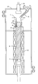
- FIG. 1 is a longitudinal sectional view showing a schematic configuration example and a use state of a heat retaining board in an electromagnetic casting apparatus of the present invention.
- FIG. 2 is a diagram schematically illustrating a configuration example of an electromagnetic casting apparatus suitable for manufacturing polycrystalline silicon.
- FIG. 3 is a diagram schematically showing a gap between the mold and the outer frame of the heat retaining device and an example of countermeasures against it.
- FIG. 3 (a) is a perspective view of the whole, and FIG. 3 (b) is FIG. 2 is a cross-sectional view taken along the line II of FIG. FIG.
- FIG. 4 is a diagram schematically showing the result of investigation on the presence or absence of red heat in the carbon fiber material and the outer frame fastening bolt when the silicon ingot is cast using the electromagnetic casting apparatus of the present invention.
- a) is the case where the carbon fiber material of the heat insulation board is an unbroken square ring shape
- FIG. 4B is the case where one part of the carbon fiber material is cut
- FIG. 4C is the two parts of the carbon fiber material. Is disconnected.
- An electromagnetic casting apparatus for silicon includes a conductive bottomless cooling mold in which a part of the axial direction is divided into a plurality of parts in the circumferential direction, an induction coil surrounding the mold, and a lower part of the mold. It is assumed that the electromagnetic casting apparatus has a heat retaining device for slowly cooling the silicon.
- the premise of such an electromagnetic casting apparatus is that, when producing polycrystalline silicon used as a substrate material for a solar cell, casting is performed in a mold with almost no contact between the molten silicon and the mold. This is because it is possible to manufacture a silicon ingot that is free from metal contamination and can maintain good conversion efficiency. It is not necessary to use a high-purity material as the mold material, and since it can be continuously cast, the manufacturing cost can be significantly reduced.
- a feature of the electromagnetic casting apparatus of the present invention is that a heat insulation board that fills a gap between the mold and the outer frame of the heat insulation apparatus is disposed on the outer frame of the heat insulation apparatus, and the heat insulation board is thermally insulated on the carbon fiber material. The material is to be placed.
- FIG. 1 is a longitudinal sectional view showing a schematic configuration example and a usage state of a heat insulating board arranged on an outer frame of a heat retaining device in order to fill a gap between a mold and the outer frame of the heat retaining device in an electromagnetic casting apparatus of the present invention.
- a heat insulating board 8 that fills a gap between the mold 1 and the outer frame 6 of the heat retaining device 3 is disposed on the outer frame 6 of the heat retaining device 3 for retaining the ingot 9.
- the heat insulation board 8 is composed of a carbon fiber material 8a and a heat insulating material 8b placed thereon.
- the heat retaining device 3 has a heating means 4 (electric heating heater) and a heat insulating material 5, and a stainless steel outer frame 6 is attached to the outside thereof. As shown in FIG. 3, the external appearance of the heat retaining device 3 is usually rectangular according to the shape of the mold 1, and four stainless steel plates are attached.
- the heater has three stages, and a plurality of heaters are arranged in each stage.
- Each heater can be controlled in temperature independently, and is configured to control the temperature in the height direction in the heat retaining device 3 with high accuracy.
- thermal insulation board on the outer frame of the thermal insulation device to fill the gap between the mold and the outer frame of the thermal insulation device reduces the thermal insulation effect due to heat dissipation through the gap, and the temperature environment inside the thermal insulation device changes. This is to prevent the casting under the same conditions and the difficulty in stable operation.
- the heat insulation board shall be made of a heat insulating material placed on a carbon fiber material. If the heat insulation board is composed of only heat insulation material, it will become fragile with repeated use and will be removed. This is because the plate may not be maintained because it is damaged or fragile, and removal may be extremely difficult. By placing the carbon fiber material under the heat insulating material, it is possible to remove it even when the state of the plate is not maintained due to damage or the like.
- the heat insulating material on the carbon fiber material is not an integral structure (that is, a square ring shape without a cut), and is previously divided into several parts. If the insulation is made into an integral structure, it will break easily due to the temperature difference between the outside and inside, and after removal it will have to be replaced with a new one in the next casting. Since it becomes possible to replace
- the carbon fiber material may be formed into a plate shape.
- the thickness may be about 5 mm. With such a thickness, there is strength that can hold the heat insulating material, and handling is relatively easy.
- the carbon fiber material is cut at least at one location.
- the carbon fiber material is heated red
- the outer frame of the heat retaining device is heated and melted
- the outer frame fastening bolts are heated red.
- the heat generated by the outer frame itself, melting damage, and red heat of the bolts for fastening the outer frame were also generated in the electromagnetic casting apparatus in which the heat insulating board made only of the conventional heat insulating material was arranged, but the carbon fiber material was used as a reinforcing material. Even if the used heat insulation board is used, the situation (outer frame, heat generation of bolt, melting damage) is not improved.
- FIG. 4 is a survey on the presence or absence of red heat in the carbon fiber material and the outer frame fastening bolt when the silicon ingot is cast using the electromagnetic casting apparatus of the present invention (cross-sectional dimension of the water-cooled copper mold: 345 mm ⁇ 505 mm).
- (a) is the case where the carbon fiber material of a heat retention board is a square ring shape without a break
- (b) is the case where one part of a carbon fiber material is cut
- (c) is This is a case where two portions of the carbon fiber material are cut.
- the hatched portion represents red heat.
- the interval between the cut surfaces and the cut site when the square ring-shaped carbon fiber material is cut in advance are not particularly limited.
- the gap between the cut surfaces needs to be wide enough so that no discharge occurs between the two surfaces.
- the gap is too wide, it will not be possible to stably place the heat insulating material when configuring the heat insulation board. Is determined by itself.
- the cutting site is appropriately determined in consideration of the influence on the outer frame and the bolt of the heat retaining device each time. In general, it is desirable to cut at a portion that is symmetrical (see FIGS. 4B and 4C).
- a member made of silicon carbide or alumina is used instead of the carbon fiber material as a reinforcing member of the heat insulating board that fills the gap between the mold and the outer frame of the heat insulating device. Can do.
- Silicon carbide and alumina are both non-conductive members, and no induced current is generated by the magnetic force from the induction coil for heating. Therefore, the reinforcing member is red hot and the influence does not reach the surrounding outer frame and bolt, and silicon carbide and alumina are desirable as the reinforcing member of the heat insulation board.
- silicon carbide is expensive and difficult to use, but both silicon carbide and alumina sufficiently satisfy the performance required as a reinforcing material for heat insulation boards. It can be applied by taking advantage of the fact that it does not flow and does not generate heat itself.
- the electromagnetic casting apparatus of the present invention uses carbon fiber material or silicon carbide or alumina as a reinforcing material for a heat insulating board made of a heat insulating material for filling a gap between the mold and the outer frame of the heat insulating device.
- carbon fiber material or silicon carbide or alumina as a reinforcing material for a heat insulating board made of a heat insulating material for filling a gap between the mold and the outer frame of the heat insulating device.
- the heat insulation board can be easily removed, and the heat insulation can be used efficiently without waste.
- the outer frame of the heat retaining device and the fastening bolts on the outer frame are prevented from red heat and melting damage, the temperature environment in the heat retaining device is prevented from changing, and stable operation is performed.
- Polycrystalline silicon suitable as a battery substrate material can be produced. Therefore, the present invention can be effectively used in the manufacturing field of solar cells, and can greatly contribute to the progress of natural energy utilization technology.
Landscapes
- Chemical & Material Sciences (AREA)
- Organic Chemistry (AREA)
- Inorganic Chemistry (AREA)
- Silicon Compounds (AREA)
- Continuous Casting (AREA)
Abstract
無底冷却モールドと、加熱用誘導コイルと、前記モールドの下方に配置され、凝固したシリコンを徐冷する保温装置を有し、前記誘導コイルによる電磁誘導加熱により溶融したシリコンを下方に引き下げ凝固させるシリコンの電磁鋳造装置であって、モールド(1)と保温装置(3)の外枠(6)との間の隙間に、炭素繊維材(8a)の上に断熱材(8b)が載置されてなる保温ボード(8)が配置された電磁鋳造装置である。前記炭素繊維材は、少なくとも1箇所で切断されていることが望ましい。これにより、保温装置内の温度環境の変化を防止して安定した操業を行い、金属不純物による汚染のない、太陽電池の基板材として好適な多結晶シリコンを製造することができる。
Description
本発明は、電磁誘導による連続鋳造技術を適用してシリコンインゴットを製造することができるシリコンの電磁鋳造装置に関し、特に、太陽電池の基板材として用いられる多結晶シリコンを、金属による汚染を生じさせずに、効率よく製造することができるシリコンの電磁鋳造装置に関する。
周方向に分割された無底の冷却モールドが取り付けられた電磁誘導による連続鋳造装置(以下、「電磁鋳造装置」という)を使用すれば、溶解された物質(ここでは、溶融シリコン)とモールドとはほとんど接触しないので、不純物汚染のない鋳塊(シリコンインゴット)を製造することができる。モールドからの汚染がないので、モールドの材質として高純度材料を使用する必要がないという利点もあり、また、連続して鋳造することができるので、製造コストの大幅な低下が可能である。したがって、電磁鋳造装置は、従来から太陽電池の基板材として用いられる多結晶シリコンの製造に適用されてきた。
図2は、多結晶シリコンの製造に好適な電磁鋳造装置の構成例を模式的に示す図である。同図に示すように、加熱用誘導コイル2の内側に、内部を水冷できる縦方向に長い銅製の板状片が、誘導コイル2の巻き軸方向と平行に、かつ誘導コイル2内では相互に絶縁された状態で配列されており、この板状片によって囲まれた空間がモールド(すなわち、側壁部が水冷されている無底の冷却モールド)1を構成する。冷却モールド1には、通常、板状片を銅片とした水冷銅モールドが用いられる。
加熱用誘導コイル2の下端位置(すなわち、冷却モールド1の底部に相当する位置)には下方に移動できる支持台11が設置されている。また、加熱用誘導コイル2の下側には、凝固した鋳塊(シリコンインゴット9)を加熱して、急激な冷却を防ぐための保温装置3が設置されており、保温装置3の下側には、均熱筒12が取り付けられている。シリコンインゴット9は引抜き装置(図示せず)により下方に引き抜かれる。
冷却モールド1の上方には、溶解中に原料をモールド1内に投入できる原料投入機13が設置されている。さらに、この例では、モールド1の上方に、必要に応じて原料シリコンを加熱するための発熱体14が取り付けられている。発熱体14としてプラズマトーチを配置し、必要に応じてプラズマアークによる加熱を行うのが望ましい。
これらの諸装置は、溶融シリコン15および高温のシリコンインゴット9が大気と直接触れることがないように、密閉容器10内に設置され、通常は、容器10内を不活性ガスで置換して、若干の加圧状態で連続鋳造が行えるように構成されている。
多結晶シリコンの製造に際しては、モールド1にシリコン原料を充填し、加熱用誘導コイル2に高周波誘導電流を通じると、原料は発熱し、溶解する。モールド1内の溶融シリコン15は、誘導電流により板状片と反発し、モールド1の側壁とは接触しない。溶融シリコン15が十分均一化した後、支持台11を少しずつ下方に移動させていけば、誘導コイル2から離れることにより冷却が始まり、モールド1内の溶融シリコン15に向けての一方向性凝固が進行してモールド断面と同じ形状の断面を有するシリコンインゴット9が形成される。
支持台11の下方への移動分に対応して溶融シリコン15の量が減少するので、その分の原料シリコンを原料投入機13から供給し、溶融シリコン15の上面が常に同じ高さレベルを保つようにして、加熱溶解、引き抜き、原料供給を継続していくことにより、多結晶シリコンインゴット9を連続して製造することができる。
ところで、前記冷却モールド1の側壁の下端外縁部と保温装置3の外枠の上端内縁部との間には隙間(図2中に破線で囲み、符号aを付した部分で、以下、単に「モールドと保温装置の外枠との間の隙間」という)が形成されている。これは、モールドと保温装置の断面寸法が異なることによるものであり、その間隔が広くなるに伴い、保温効果の低下が大きくなり、保温装置内の温度環境が変化して、同一条件での鋳造ができなくなって安定した操業が困難となる。したがって、隙間を断熱材からなる保温ボードで覆う等の対策が講じられている。
モールドと保温装置の外枠との間の隙間を小さくするために、保温ボードを保温装置の外枠と一体型にすることも可能であるが、保温ボードは劣化が激しいので、通常は、保温装置とは別の、容易に交換できる部品構成としている。
図3は、モールドと保温装置の外枠との間の隙間およびそれに対する対策例を模式的に示す図で、(a)は全体の斜視図、(b)は(a)のI-I矢視断面図である。
図3に示すように、モールド1の外側に加熱用誘導コイル2が取り付けられ、モールド1の下方にインゴット9を保温するための保温装置3が設置されている。このモールド1と保温装置3の外枠6(その内側に断熱材5が取り付けられている)との間に隙間(図3(b)中に破線で囲んだ部分)が形成されており、図示した例では、その隙間に断熱材からなる保温ボード8が取り付けられている。断熱材としては、アルミナおよびシリカを主成分とした高耐熱の断熱ボードが使用されている。
しかしながら、この断熱材の保温ボードは、断熱性には優れているものの、使用を重ねていくうちに脆くなるという欠点がある。保温ボードは、1回の鋳造を終了する毎に取り外す必要があるが、脆くなっているために取り外しが容易ではなく、破損が生じやすいという問題がある。
この電磁鋳造装置におけるモールドと保温装置の外枠との間の隙間対策について、特許公報その他の文献で公にされたものは見当たらない。しかし、類似する隙間対策として、例えば、特許文献1には、炉頂に開口する鋼板の挿入・抽出口を備えたバッチ式加熱炉において、保温カバー装置の下端を前記挿入・抽出口に埋没させて炉を密封するに際し、挿入・抽出口周縁に弾性体であるフェルトを配して炉内の熱や雰囲気ガスの大気中への漏洩を遮断する保温カバー装置が開示されている。フェルトの材質についての記載はないが、繊維状の耐火材が素材として使用されていると考えられる。
同文献に記載されるフェルトは、前記モールドと保温装置の外枠との間の隙間が狭い場合には、適用の可能性も考えられる。しかし、隙間が比較的広い場合、フェルトには剛性がないので適用が難しく、断熱効果においても十分ではないと考えられる。
本発明はこのような状況に鑑みてなされたもので、モールドと保温装置の外枠との間の隙間に、強度および耐久性に優れ、取り付け取り外しが容易な保温ボードを配置することにより、保温装置内の温度環境の変化を防止して安定した操業を行い、しかも、金属不純物による汚染のない、太陽電池の基板材として好適な多結晶シリコンを製造することができるシリコンの電磁鋳造装置を提供することを目的としている。
本発明者は、上記の課題を解決するために、現在使用している断熱材からなる保温ボードの補強を考えた。すなわち、当該断熱材は使用により脆くなるという欠点があり、交換時に破損し易くなるので、補強材を使用して、この補強材の上に断熱材を載置する方法について検討した。
断熱材からなる保温ボードの補強材としては、適度な強度を有すること、高耐熱性であること、熱変形に耐えられること等が要求される。これらの要求を満たす材料として、アルミナ、炭化珪素等のセラミックスや、モリブデン、タンタル、タングステン等の高融点金属などが適用できる可能性がある。これらのうち、高融点金属は金属汚染が生じるおそれがあるので望ましくない。また、炭化珪素等のセラミックスは、コスト高になるという難点がある。
そこで、保温ボードの補強材として、前記の要求を満たすと考えられる繊維状断熱材(但し、高温に耐える無機質材)の適用を検討した。繊維状断熱材は、断熱性能が高く、フェルト状、バルク状、板状などとして、あるいは、吹付け材、複合材料の充填材として多用されている。このうちの、特に炭素繊維材で板状に成形されたものは、比較的安価で、割れたりすることもなく、取り扱いが容易であり、保温ボードを保持するための補強材として十分適用が可能と考えられる。
まず、断面寸法が345mm×505mmの水冷銅モールドを有する電磁鋳造装置において、厚さが5mm程度の炭素繊維材の上に断熱材を載せてドーナツ形の(角形リング状の)保温ボードとし、モールドと保温装置の外枠との間の隙間を覆うように載置して(つまり、保温ボードで隙間を埋めて)、長さ4000mmのシリコンインゴットを鋳造した。その結果、断熱材は脆くなったが、その下の炭素繊維材には何ら異常はなく、断熱材と炭素繊維材とを一体として容易に取り外しができることを確認した。
ところが、一方で、断熱材とともに保温ボードを構成する炭素繊維材が赤熱した。また、従来の断熱材のみからなる保温ボードの使用中にも生じていた問題であるが、保温装置の外枠自体が発熱、溶損し、また外枠を締結するためのボルトの赤熱が認められた。
前記図3に示したように、保温装置3は、加熱手段4(電熱式のヒーター)および断熱材5を有し、その外周に加熱手段4および断熱材5を支持し固定するための外枠6が取り付けられている。この外枠6は、4枚(面)のステンレス鋼製の板からなり、互いに隣接する2枚毎に絶縁材を挟んで金属製のボルト7で締結されている。外枠自体の溶損や、外枠締結用のボルトの赤熱は、加熱用誘導コイルからの磁力による誘導電流が、断熱材の補強に用いた炭素繊維材に流れてこれを赤熱させ、その影響が周辺の外枠やボルトに及んだことに加え、誘導コイルから外枠やボルトへの直接の影響もあったものと考えられる。
外枠の溶損は、外枠6を構成する4枚の板材のうち、誘導コイル2の支持部(図3(a)中に符号bを付した部分)の直下に位置する面(この面を、以下「B面」ともいう)で特に大きかった。外枠6には、ヒーターの電極や、保温装置3内の温度を測定するための熱電対(いずれも図示せず)が取り付けられているが、B面に取り付けられた熱電対の破損も多かった。また、外枠締結用のボルトは金属製なので、誘導電流がボルトに集中してボルトが赤熱し、さらには溶損する場合もあった。
保温装置の外枠やボルトが赤熱、溶損すると、雰囲気中に金属汚染物質が導入されることとなりシリコンインゴットが汚染される。金属不純物は、太陽電池としての変換効率(入射した光のエネルギーに対し、電気エネルギーに変換して取り出すことができるエネルギーの割合)を低下させるので、太陽電池の基板材として用いられる多結晶シリコンの製造においては特に厳重な管理が必要とされる。また、外枠の寿命が短くなるだけではなく、保温効果が低下し、保温装置内の温度環境が変化して、安定した操業が困難となる。
このような炭素繊維材の赤熱や、保温装置の外枠、外枠締結用のボルトの赤熱、溶損は、加熱用誘導コイルからの磁力による誘導電流が流れたことによるものであることから、本発明者は、角形リング状の炭素繊維材の1箇所または2箇所をあらかじめ切断して、前記誘導電流の流れを遮ることを試みた。その結果、炭素繊維材の赤熱を防止することができ、また、外枠の溶損やボルトの赤熱を防止し得ることを確認した。
さらに、モールドと保温装置の外枠との間の隙間を埋める保温ボードの補強材としては、炭素繊維材に替えて炭化珪素製またはアルミナ製の部材も使用可能であることを確認した。これらの部材はいずれも非導電性部材であって、誘導電流が流れることはなく、それら自体が発熱することはない。
本発明はこのような知見に基づいてなされたもので、下記のシリコンの電磁鋳造装置を要旨とする。
すなわち、軸方向の一部が周方向で複数に分割された導電性の無底冷却モールドと、このモールドを取り囲む誘導コイルと、前記モールドの下方に配置され、凝固したシリコンを徐冷する保温装置を有し、前記誘導コイルによる電磁誘導加熱により溶融したシリコンを下方に引き下げ凝固させるシリコンの電磁鋳造装置であって、前記保温装置の外枠上に、前記モールドと保温装置の外枠の間の隙間を埋める保温ボードが配置され、当該保温ボードは炭素繊維材の上に断熱材が載置されてなることを特徴とする電磁鋳造装置である。
すなわち、軸方向の一部が周方向で複数に分割された導電性の無底冷却モールドと、このモールドを取り囲む誘導コイルと、前記モールドの下方に配置され、凝固したシリコンを徐冷する保温装置を有し、前記誘導コイルによる電磁誘導加熱により溶融したシリコンを下方に引き下げ凝固させるシリコンの電磁鋳造装置であって、前記保温装置の外枠上に、前記モールドと保温装置の外枠の間の隙間を埋める保温ボードが配置され、当該保温ボードは炭素繊維材の上に断熱材が載置されてなることを特徴とする電磁鋳造装置である。
本発明のシリコンの電磁鋳造装置において、前記炭素繊維材が少なくとも1箇所で切断されているものであれば、炭素繊維材における誘導電流の発生を抑えることができるので望ましい。
本発明のシリコンの電磁鋳造装置において、前記炭素繊維材に替えて炭化珪素製またはアルミナ製の部材が使用されているものであれば、当該炭化珪素製またはアルミナ製の部材に、加熱用誘導コイルからの磁力による誘導電流が生じることはなく、望ましい。
本発明のシリコンの電磁鋳造装置は、モールドと保温装置の外枠の間の隙間が炭素繊維材の上に断熱材が載置された保温ボードで覆われた鋳造装置である。炭素繊維材に替えて炭化珪素製またはアルミナ製部材の使用も可能である。
本発明の電磁鋳造装置を使用すれば、保温ボードの断熱材が使用中に脆くなっても、炭素繊維材により保持されているので、保温ボードの取り外しを容易に行うことができる。断熱材をあらかじめ数分割して使用に供し、劣化の激しい部分だけを交換することができるので、断熱材を無駄なく有効に使用することが可能になる。
また、リング状の炭素繊維材を少なくとも1箇所、望ましくは2箇所で切断しておくことにより、保温装置の外枠や、外枠の締結用ボルトの赤熱、溶損を防止し、保温装置内の温度環境の変化を防止して安定した操業を行い、金属不純物による汚染のない、太陽電池の基板材として好適な多結晶シリコンを製造することができる。
本発明のシリコンの電磁鋳造装置は、軸方向の一部が周方向で複数に分割された導電性の無底冷却モールドと、このモールドを取り囲む誘導コイルと、前記モールドの下方に配置され、凝固したシリコンを徐冷する保温装置を有する電磁鋳造装置であることを前提としている。
このような電磁鋳造装置を前提とするのは、太陽電池の基板材として用いられる多結晶シリコンを製造するに際し、モールド内で、溶融シリコンとモールドとをほとんど接触させずに鋳造を行い、モールドからの金属汚染がなく、変換効率を良好に維持できるシリコンインゴットを製造することができるからである。モールドの材質として高純度材料を使用する必要がなく、また、連続して鋳造することができるので、製造コストの大幅な低下も可能である。
本発明の電磁鋳造装置の特徴は、前記保温装置の外枠上に、前記モールドと保温装置の外枠の間の隙間を埋める保温ボードが配置され、当該保温ボードは炭素繊維材の上に断熱材が載置されてなることにある。
図1は、本発明の電磁鋳造装置において、モールドと保温装置の外枠の間の隙間を埋めるために保温装置の外枠上に配置されている保温ボードの概略構成例および使用状態を示す縦断面図である。図1に示すように、インゴット9を保温するための保温装置3の外枠6上に、前記モールド1と保温装置3の外枠6の間の隙間を埋める保温ボード8が配置されている。当該保温ボード8は炭素繊維材8aと、その上に載置された断熱材8bとで構成されている。
保温装置3は、加熱手段4(電熱式のヒーター)および断熱材5を有し、その外側にステンレス鋼製の外枠6が取り付けられている。保温装置3の外観は、前記図3に示したように、通常、モールド1の形状に合わせて方形であり、4枚のステンレス鋼製の板材が取り付けられている。
図1に示した例では、ヒーターは3段であり、各段において、複数のヒーターが配置されている。各ヒーターはそれぞれ独立して温度制御が可能であり、保温装置3内の高さ方向における温度を高精度で制御できるように構成されている。
保温装置の外枠上に、モールドと保温装置の外枠の間の隙間を埋める保温ボードを配置するのは、隙間を通しての放熱のため保温効果が低下し、保温装置内の温度環境が変化して同一条件での鋳造ができず、安定した操業が困難となるのを防止するためである。
保温ボードは炭素繊維材の上に断熱材が載置されてなるものとするのは、保温ボードが断熱材のみで構成されている場合は、使用を重ねていくうちに脆くなり、取り外しの際に破損したり、脆いため板の状態を維持できず、取り外しが極めて困難になる場合があるからである。炭素繊維材を断熱材の下に置くことにより、破損等で板の状態が維持されなくなった場合でも取り外しが可能になる。
炭素繊維材の上の断熱材は、一体構造(すなわち、切れ目のない角形のリング状)とせず、あらかじめ数分割しておくことが望ましい。断熱材を一体構造にすると、外側と内側の温度差により割れやすく、取り外し後、次の鋳造ではすべてを新品に交換しなければならないが、数分割しておくことにより、劣化の激しい部分だけを交換することが可能になるので、断熱材を無駄にせず、全体を有効に使用することができる。なお、前記分割数は、断熱材の割れや脆化の状態をみて適宜定めればよい。
炭素繊維材は、板状に成形されたものを用いればよい。厚さは、5mm程度とすればよい。この程度の厚さがあれば、断熱材を保持できる強度があり、取り扱いも比較的容易である。
本発明のシリコンの電磁鋳造装置において、前記炭素繊維材が少なくとも1箇所で切断されているものとするのが望ましい。
前述のように、角形リング状の炭素繊維材を使用した場合、炭素繊維材が赤熱するとともに、保温装置の外枠自体が発熱、溶損し、また外枠締結用ボルトが赤熱する。この外枠自体の発熱、溶損、および外枠締結用ボルトの赤熱は、従来の断熱材のみからなる保温ボードが配置された電磁鋳造装置においても生じていたが、炭素繊維材を補強材として使用した保温ボードを使用しても、その状況(外枠、ボルトの発熱、溶損)は改善されない。これは、加熱用誘導コイルからの磁力による誘導電流が、炭素繊維材に流れてこれを赤熱させ、その影響が周辺の外枠やボルトに及ぶとともに、誘導コイルから外枠やボルトへの直接の影響もあったものと考えられる。
そこで、角形リング状の炭素繊維材の1箇所または2箇所をあらかじめ切断しておくこととすれば、加熱用誘導コイルからの磁力による誘導電流の流れを抑え、炭素繊維材の赤熱を防止し、さらには、外枠の溶損やボルトの赤熱を防止することが可能となる。
図4は、本発明の電磁鋳造装置(水冷銅モールドの断面寸法:345mm×505mm)を用いてシリコンインゴットの鋳造を行ったときの炭素繊維材および外枠締結用ボルトにおける赤熱の有無についての調査結果を模式的に示す図で、(a)は保温ボードの炭素繊維材が切れ目のない角形リング状の場合、(b)は炭素繊維材の1箇所が切断されている場合、(c)は炭素繊維材の2箇所が切断されている場合である。なお、図4において、斜線を付した部分は赤熱していることを表す。
図4(a)に示すように、保温ボードの炭素繊維材8aが切れ目のない角形リング状の場合は、炭素繊維材8aの外周全面が赤熱していた。炭素繊維材8aの内周も赤熱していると推測される。締結用ボルト7も赤熱していた。
炭素繊維材の1箇所が切断されている場合は、図4(b)に示すように、炭素繊維材8aに赤熱は認められなかった。しかし、締結用ボルト7は赤熱していた。
一方、炭素繊維材の2箇所が切断されている場合は、図4(c)に示すように、炭素繊維材8aに赤熱は認められなかった。締結用ボルト7にも赤熱は認められなかったが、これは、炭素繊維材を2箇所で切断することにより、加熱用誘導コイルの磁場分布が大きく変化し、誘導電流のボルトへの集中が阻まれたことによるものと推察される。
図4に示したように、切断箇所は1箇所でも効果はあるが、2箇所で切断するのがより望ましい。
角形リング状の炭素繊維材をあらかじめ切断しておく際の切断面の間隔および切断部位は特に限定しない。切断面の間隔は、両面間で放電が起こらない程度の開きが必要であり、一方、間隔が広すぎると保温ボードを構成する際に断熱材を安定して載置できなくなるので、適正な間隔は自ずと定まる。また、切断部位は、切断による誘導コイルの磁場分布の変化を的確に予測することは困難なので、保温装置の外枠やボルトへの影響をその都度勘案しつつ適宜定めるのがよい。一般的には、左右対称となるような部位で切断するのが望ましい(前記図4の(b)、(c)参照)。
本発明のシリコンの電磁鋳造装置においては、モールドと保温装置の外枠の間の隙間を埋める保温ボードの補強部材として、前記炭素繊維材に替えて炭化珪素製またはアルミナ製の部材を使用することができる。
炭化珪素、およびアルミナはいずれも非導電性部材であり、加熱用誘導コイルからの磁力による誘導電流が生じることはない。したがって、補強部材が赤熱し、その影響が周辺の外枠やボルトに及ぶことはなく、炭化珪素およびアルミナは保温ボードの補強部材として望ましい。特に炭化珪素は高価なので利用しにくい面はあるが、炭化珪素およびアルミナはいずれも保温ボードの補強材として要求される性能を十分に満たしているので、加熱用誘導コイルからの磁力による誘導電流が流れることはなく、それら自体が発熱することはないという特徴を生かした適用が可能である。
以上説明したように、本発明の電磁鋳造装置は、モールドと保温装置の外枠の間の隙間を埋めるための断熱材からなる保温ボードの補強材として炭素繊維材または炭化珪素やアルミナを使用している点にある。これにより、断熱材が脆くなり、形をなさない状態になっても保温ボードの取り外しを容易に行うことができ、また、使用に際し、炭素繊維材等の上に載置する断熱材をあらかじめ数分割しておくことにより、断熱材の無駄のない効率的な利用が可能になる。
炭素繊維材を角形リング状のままで使用する限りにおいては、従来の断熱材のみからなる保温ボードを使用している場合にも生じていた保温装置の外枠自体の発熱、溶損や、外枠締結用ボルトの赤熱等の改善はなされないが、炭素繊維材を少なくとも1箇所、望ましくは2箇所で切断しておくことにより、前記外枠やボルトの赤熱、溶損を防止することが可能になる。
本発明の電磁鋳造装置を使用すれば、保温ボードの取り外しを容易に行うことができ、しかも、断熱材の無駄のない効率的な使用が可能になる。また、保温装置の外枠や、外枠の締結用ボルトの赤熱、溶損を防止し、保温装置内の温度環境の変化を防止して安定した操業を行い、金属不純物による汚染のない、太陽電池の基板材として好適な多結晶シリコンを製造することができる。
したがって、本発明は、太陽電池の製造分野において有効に利用することができ、自然エネルギー利用技術の進展に大きく寄与することができる。
したがって、本発明は、太陽電池の製造分野において有効に利用することができ、自然エネルギー利用技術の進展に大きく寄与することができる。
1:モールド、 2:加熱用誘導コイル、 3:保温装置、
4:加熱手段、 5:断熱材、 6:外枠、 7:ボルト、
8:保温ボード、 8a:炭素繊維材、 8b:断熱材、
9:シリコンインゴット、 10:密閉容器、
11:支持台、 12:均熱筒、 13:原料投入機、
14:発熱体、 15:溶融シリコン
4:加熱手段、 5:断熱材、 6:外枠、 7:ボルト、
8:保温ボード、 8a:炭素繊維材、 8b:断熱材、
9:シリコンインゴット、 10:密閉容器、
11:支持台、 12:均熱筒、 13:原料投入機、
14:発熱体、 15:溶融シリコン
Claims (3)
- 軸方向の一部が周方向で複数に分割された導電性の無底冷却モールドと、このモールドを取り囲む誘導コイルと、前記モールドの下方に配置され、凝固したシリコンを徐冷する保温装置を有し、前記誘導コイルによる電磁誘導加熱により溶融したシリコンを下方に引き下げ凝固させるシリコンの電磁鋳造装置であって、
前記保温装置の外枠上に、前記モールドと保温装置の外枠の間の隙間を埋める保温ボードが配置され、当該保温ボードは炭素繊維材の上に断熱材が載置されてなることを特徴とするシリコンの電磁鋳造装置。 - 前記炭素繊維材が少なくとも1箇所で切断されていることを特徴とする請求項1に記載のシリコンの電磁鋳造装置。
- 前記炭素繊維材に替えて炭化珪素製またはアルミナ製の部材が使用されていることを特徴とする請求項1に記載のシリコンの電磁鋳造装置。
Applications Claiming Priority (2)
| Application Number | Priority Date | Filing Date | Title |
|---|---|---|---|
| JP2010180063A JP2012036059A (ja) | 2010-08-11 | 2010-08-11 | シリコンの電磁鋳造装置 |
| JP2010-180063 | 2010-08-11 |
Publications (1)
| Publication Number | Publication Date |
|---|---|
| WO2012020463A1 true WO2012020463A1 (ja) | 2012-02-16 |
Family
ID=45567444
Family Applications (1)
| Application Number | Title | Priority Date | Filing Date |
|---|---|---|---|
| PCT/JP2010/006743 Ceased WO2012020463A1 (ja) | 2010-08-11 | 2010-11-17 | シリコンの電磁鋳造装置 |
Country Status (3)
| Country | Link |
|---|---|
| JP (1) | JP2012036059A (ja) |
| TW (1) | TW201207170A (ja) |
| WO (1) | WO2012020463A1 (ja) |
Families Citing this family (1)
| Publication number | Priority date | Publication date | Assignee | Title |
|---|---|---|---|---|
| KR102271716B1 (ko) | 2020-09-28 | 2021-07-01 | 한화솔루션 주식회사 | 잉곳 성장 장치 |
Citations (6)
| Publication number | Priority date | Publication date | Assignee | Title |
|---|---|---|---|---|
| JPS6453733A (en) * | 1987-08-25 | 1989-03-01 | Osaka Titanium | Method for casting silicon |
| JPH07215714A (ja) * | 1994-01-28 | 1995-08-15 | Sharp Corp | 多結晶シリコン製造方法および多結晶シリコン製造用坩堝 |
| WO2002053496A1 (fr) * | 2000-12-28 | 2002-07-11 | Sumitomo Mitsubishi Silicon Corporation | Procede de moulage en continu de silicium |
| WO2006088037A1 (ja) * | 2005-02-17 | 2006-08-24 | Sumco Solar Corporation | シリコン鋳造装置およびシリコン基板の製造方法 |
| JP2007051026A (ja) * | 2005-08-18 | 2007-03-01 | Sumco Solar Corp | シリコン多結晶の鋳造方法 |
| JP2008174397A (ja) * | 2007-01-16 | 2008-07-31 | Sumco Solar Corp | 多結晶シリコンの鋳造方法 |
-
2010
- 2010-08-11 JP JP2010180063A patent/JP2012036059A/ja active Pending
- 2010-11-17 WO PCT/JP2010/006743 patent/WO2012020463A1/ja not_active Ceased
- 2010-11-24 TW TW99140567A patent/TW201207170A/zh unknown
Patent Citations (6)
| Publication number | Priority date | Publication date | Assignee | Title |
|---|---|---|---|---|
| JPS6453733A (en) * | 1987-08-25 | 1989-03-01 | Osaka Titanium | Method for casting silicon |
| JPH07215714A (ja) * | 1994-01-28 | 1995-08-15 | Sharp Corp | 多結晶シリコン製造方法および多結晶シリコン製造用坩堝 |
| WO2002053496A1 (fr) * | 2000-12-28 | 2002-07-11 | Sumitomo Mitsubishi Silicon Corporation | Procede de moulage en continu de silicium |
| WO2006088037A1 (ja) * | 2005-02-17 | 2006-08-24 | Sumco Solar Corporation | シリコン鋳造装置およびシリコン基板の製造方法 |
| JP2007051026A (ja) * | 2005-08-18 | 2007-03-01 | Sumco Solar Corp | シリコン多結晶の鋳造方法 |
| JP2008174397A (ja) * | 2007-01-16 | 2008-07-31 | Sumco Solar Corp | 多結晶シリコンの鋳造方法 |
Also Published As
| Publication number | Publication date |
|---|---|
| JP2012036059A (ja) | 2012-02-23 |
| TW201207170A (en) | 2012-02-16 |
Similar Documents
| Publication | Publication Date | Title |
|---|---|---|
| JP4585606B2 (ja) | 連続鋳造方法及びノズル加熱装置 | |
| US7682472B2 (en) | Method for casting polycrystalline silicon | |
| CN103038167B (zh) | 硅的电磁铸造装置 | |
| CN105964992B (zh) | 定向凝固系统和方法 | |
| KR20130113422A (ko) | 다결정성 규소 블록을 생산하기 위한 방법 및 장치 | |
| US20060037733A1 (en) | Electromagnetic continuous casting apparatus for materials possessing high melting temperature and low electric conductance | |
| US8780952B2 (en) | Roof system for electric arc furnace and method for manufacturing the same | |
| JP2002293526A (ja) | 多結晶シリコンの製造装置 | |
| WO2012020463A1 (ja) | シリコンの電磁鋳造装置 | |
| KR20140017507A (ko) | 단결정 인상장치 및 단결정 인상장치에 이용되는 저열전도성 부재 | |
| KR101457831B1 (ko) | 고리형상 청정금속 주형 | |
| JP5371701B2 (ja) | 多結晶シリコンインゴットの製造装置及び多結晶シリコンインゴットの製造方法 | |
| JP2012041209A (ja) | シリコンの電磁鋳造装置 | |
| KR20120049811A (ko) | 실리콘 잉곳의 전자 주조 장치 및 전자 주조 방법 | |
| KR20130005743A (ko) | 실리콘 잉곳의 제작을 위한 전자기 연속 주조 장치 | |
| RU2550863C2 (ru) | Установка для электромагнитного литья кремния | |
| JP4931432B2 (ja) | 多結晶シリコン鋳片製造用の鋳型 | |
| CN224186048U (zh) | 一种玄武岩纤维熔炉漏板砖快捷更换装置 | |
| AU2013204598B2 (en) | Electromagnetic casting apparatus for silicon | |
| KR101896950B1 (ko) | 진공 열처리 장치 | |
| KR20120031421A (ko) | 실리콘 잉곳의 전자 주조 방법 | |
| JP2004071172A (ja) | 加熱装置およびその製造方法並びに被膜形成装置 | |
| JP2013049586A (ja) | シリコンインゴットの連続鋳造方法 | |
| JP2006205179A (ja) | 溶鋼の連続鋳造方法 | |
| KR20120126913A (ko) | 실리콘 잉곳을 생산하는 전자기 연속 주조 장치 |
Legal Events
| Date | Code | Title | Description |
|---|---|---|---|
| 121 | Ep: the epo has been informed by wipo that ep was designated in this application |
Ref document number: 10855864 Country of ref document: EP Kind code of ref document: A1 |
|
| NENP | Non-entry into the national phase |
Ref country code: DE |
|
| 122 | Ep: pct application non-entry in european phase |
Ref document number: 10855864 Country of ref document: EP Kind code of ref document: A1 |