WO2012018064A1 - 電気的接続構造 - Google Patents
電気的接続構造 Download PDFInfo
- Publication number
- WO2012018064A1 WO2012018064A1 PCT/JP2011/067828 JP2011067828W WO2012018064A1 WO 2012018064 A1 WO2012018064 A1 WO 2012018064A1 JP 2011067828 W JP2011067828 W JP 2011067828W WO 2012018064 A1 WO2012018064 A1 WO 2012018064A1
- Authority
- WO
- WIPO (PCT)
- Prior art keywords
- groove
- bus bar
- conductor
- electrical connection
- contact
- Prior art date
- Legal status (The legal status is an assumption and is not a legal conclusion. Google has not performed a legal analysis and makes no representation as to the accuracy of the status listed.)
- Ceased
Links
Images



Classifications
-
- H—ELECTRICITY
- H01—ELECTRIC ELEMENTS
- H01R—ELECTRICALLY-CONDUCTIVE CONNECTIONS; STRUCTURAL ASSOCIATIONS OF A PLURALITY OF MUTUALLY-INSULATED ELECTRICAL CONNECTING ELEMENTS; COUPLING DEVICES; CURRENT COLLECTORS
- H01R4/00—Electrically-conductive connections between two or more conductive members in direct contact, i.e. touching one another; Means for effecting or maintaining such contact; Electrically-conductive connections having two or more spaced connecting locations for conductors and using contact members penetrating insulation
- H01R4/28—Clamped connections, spring connections
- H01R4/30—Clamped connections, spring connections utilising a screw or nut clamping member
- H01R4/304—Clamped connections, spring connections utilising a screw or nut clamping member having means for improving contact
-
- H—ELECTRICITY
- H01—ELECTRIC ELEMENTS
- H01R—ELECTRICALLY-CONDUCTIVE CONNECTIONS; STRUCTURAL ASSOCIATIONS OF A PLURALITY OF MUTUALLY-INSULATED ELECTRICAL CONNECTING ELEMENTS; COUPLING DEVICES; CURRENT COLLECTORS
- H01R25/00—Coupling parts adapted for simultaneous co-operation with two or more identical counterparts, e.g. for distributing energy to two or more circuits
- H01R25/16—Rails or bus-bars provided with a plurality of discrete connecting locations for counterparts
- H01R25/161—Details
- H01R25/162—Electrical connections between or with rails or bus-bars
-
- H—ELECTRICITY
- H01—ELECTRIC ELEMENTS
- H01R—ELECTRICALLY-CONDUCTIVE CONNECTIONS; STRUCTURAL ASSOCIATIONS OF A PLURALITY OF MUTUALLY-INSULATED ELECTRICAL CONNECTING ELEMENTS; COUPLING DEVICES; CURRENT COLLECTORS
- H01R4/00—Electrically-conductive connections between two or more conductive members in direct contact, i.e. touching one another; Means for effecting or maintaining such contact; Electrically-conductive connections having two or more spaced connecting locations for conductors and using contact members penetrating insulation
- H01R4/28—Clamped connections, spring connections
- H01R4/30—Clamped connections, spring connections utilising a screw or nut clamping member
- H01R4/34—Conductive members located under head of screw
Definitions
- the present invention relates to an electrical connection structure.
- a conductive metal plate is used to electrically connect a high-voltage harness and a terminal block and electrodes on the device side, or between battery cells of an assembled battery in which a plurality of battery cells are arranged.
- Busbar is used.
- the electrical connection with the bus bar is usually done by tightening bolts and nuts.
- the present invention has been completed based on the above circumstances, and provides an electrical connection structure capable of reducing contact resistance between conductors when electrical connection is performed by bolting. It is for the purpose.
- the present invention is an electrical connection structure, in which a metal first conductor and a second conductor made of a metal plate and having a contact surface that contacts the first conductor, the contact surface is the first contact. It is electrically connected by being bolted in a state of being in contact with one conductor, a tin plating layer is formed on the surface of the first conductor, and both a concave portion and a convex portion are formed on the contact surface. Or one is formed.
- the contact surface of the second conductor is brought into close contact with the first conductor with a relatively strong pressure by bolting.
- the opening edge and the convex portion of the concave portion formed on the contact surface are in close contact with the first conductor with a pressure stronger than the other portions.
- a tin plating layer is formed on the surface of the first conductor.
- a tin oxide film is usually formed on the surface of the tin plating layer.
- the recess is preferably a groove formed on the flat surface. Thereby, a recessed part can be formed with the simple method of forming a groove
- the convex portion is an edge formed so as to protrude from the opening edge of the groove.
- a convex part can also be formed in the process which forms the groove
- the number of work steps can be reduced as compared with the case where the convex portion is formed in a step different from the step of forming the concave portion.
- a plurality of the grooves are formed side by side at intervals. Thereby, electrical connection can be ensured.
- the groove is composed of a first groove formed in a plurality with a gap and a second groove formed in a plurality with the gap intersecting the first groove.
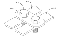
- FIG. 1 is a perspective view showing a bolted connection structure according to an embodiment of the present invention.
- FIG. 2 is a plan view showing grooves formed on the contact surface of the bus bar.
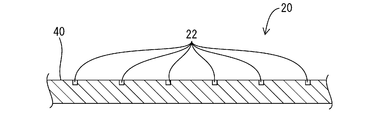
- FIG. 3 is a cross-sectional view of the bus bar of FIG.
- FIG. 4 is a graph showing the relationship between tightening torque and contact resistance.
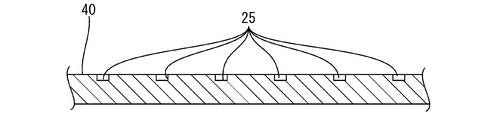
- FIG. 5 is a plan view showing grooves formed on the contact surface of the bus bar of another embodiment. 6 is a cross-sectional view of the bus bar of FIG.
- Bus bar (first conductor) 20 ...
- Bus bar (second conductor) 22 ... groove (concave) 22A ... first groove 22B ... second groove 30 ... bolt 40 ... contact surface
- each bus bar 10 is formed by bridging a bus bar (an example of a second conductor) 20 between two bus bars (an example of a first conductor) 10, 10 arranged in parallel. 10 and 20 are electrically connected.
- the bus bar 10 is made of copper and is made of a long plate material. Further, a tin plating layer having a thickness of 2 ⁇ m is formed on the surface. On the other hand, the bus bar 20 is also made of a copper plate. In the present embodiment, the surface of the bus bar 20 is not plated.
- a method of forming a tin plating layer on the surface of the bus bar 10 a known method can be used. For example, an arbitrary method is adopted as necessary, such as forming a base plating layer made of Ni or the like. sell. Moreover, the thickness of a tin plating layer can be set to arbitrary thickness dimensions as needed.
- Each bus bar 10, 10, 20 is provided with a connection hole 21 (a connection hole of the bus bar 10 is not shown) penetrating each bus bar 10, 10, 20.
- the bus bars 10 and 20 are electrically connected to each other by tightening nuts (not shown) while the bolts 30 are passed through the connection holes 21 and the bus bars 10 and 20 are sandwiched.
- An area of the bus bar 20 that contacts the bus bar 10 is a contact surface 40. As shown in FIG. 2 and FIG. 3, so-called knurling is performed on the entire surface of the bus bar 20 including the contact surface 40.
- the contact surface 40 of the bus bar 20 has a plurality of first grooves 22A (an example of a concave portion) arranged at a predetermined interval and intersects with the first groove 22A and at a predetermined interval.
- a plurality of second grooves 22 ⁇ / b> B (an example of recesses) arranged are formed.
- the first groove 22A and the second groove 22B are orthogonal to each other, and the first groove 22A and the second groove 22B have a lattice shape as a whole.
- the first groove 22A extends from the diagonally upper left to the diagonally lower right in FIG. 2
- the second groove 22B extends from the diagonally upper right to the diagonally lower left in FIG. It is extended and formed.
- the first groove 22A and the second groove 22B may be collectively referred to as the groove 22.
- an edge (an example of a convex portion) that protrudes from the contact surface 40 of the bus bar 20 when the groove 22 is formed is formed at the opening edge of the groove 22.
- Example 1 After forming a tin plating layer having a thickness of 2 ⁇ m on the surface of a copper metal plate by a known method, the bus bar 10 having a predetermined shape was formed by pressing.
- the bus bar 10 was a long plate having a width of 10 mm and a length of 100 mm. Further, a connecting hole having a diameter of 5.5 mm was formed in the bus bar 10 during the press working.
- the bus bar 20 made of a plate material of 15 mm ⁇ 35 mm ⁇ 0.8 mm was formed by pressing a copper metal plate material.
- the bus bar 20 was formed with two connecting holes 21 having a diameter of 5.5 mm at intervals of 20 mm during press working.
- a knurling process was performed on one surface of the bus bar 20 to form a plurality of lattice-shaped grooves with a pitch interval of 1.0 mm.
- the depth dimension of the groove was 0.1 mm.
- a high temperature and high humidity process was performed on the bus bars 10 and 20. More specifically, the bus bars 10 and 20 were left at a humidity of 85% and a temperature of 85 ° C. for 200 hours. Thereby, an oxide film was formed on the surfaces of the bus bars 10 and 20. A tin oxide film was formed on the surface of the bus bar 10, and a copper oxide film was formed on the surface of the bus bar 20.
- the contact resistance between the bus bar 10 and the bus bar 20 was measured for Example 1 above.
- the number of samples was four, and the average value of each sample was calculated.
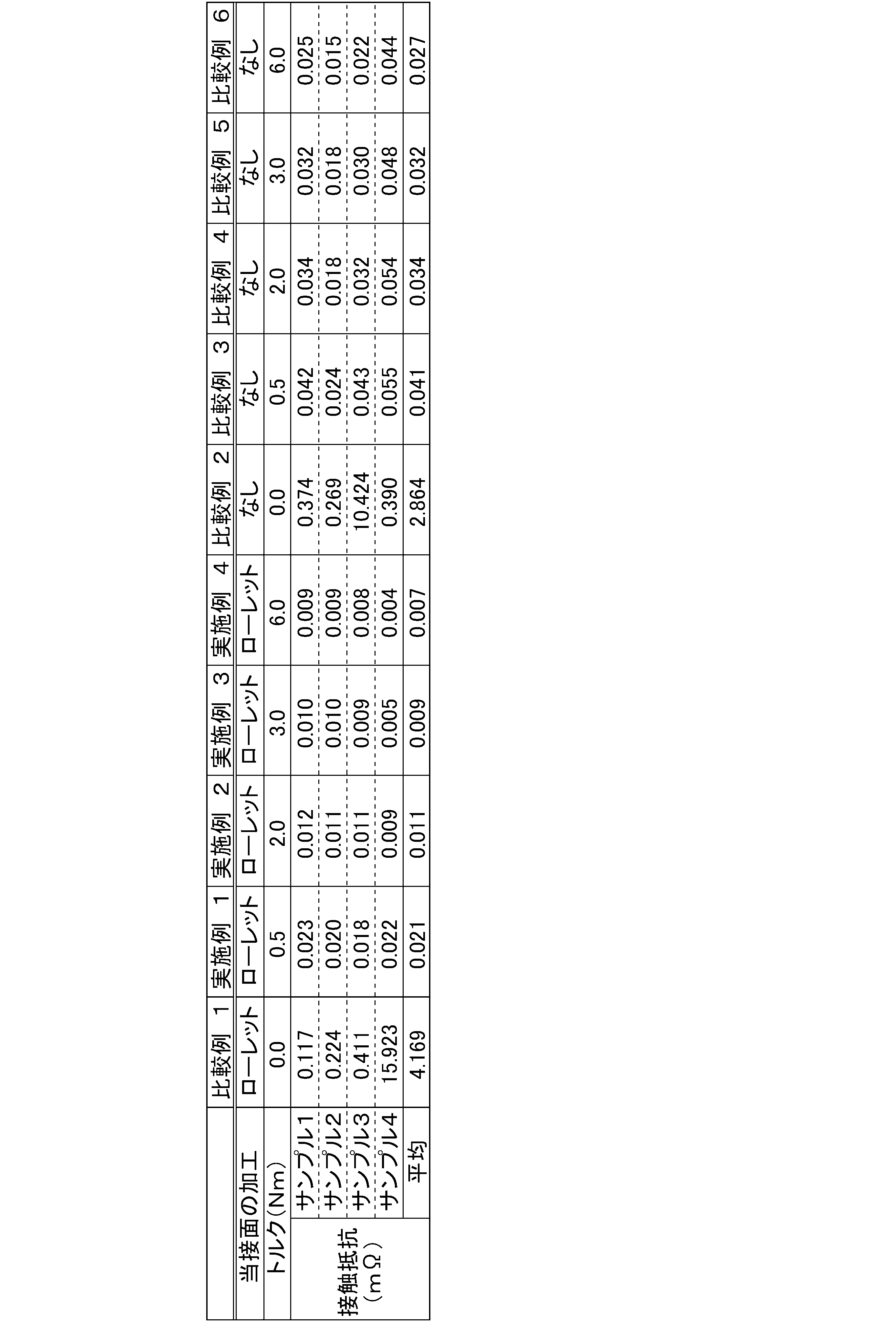
- the results are shown in Table 1. More specifically, first, as shown in FIG. 1, a pair of bus bars 10, 10 are arranged side by side, a bus bar 20 is arranged so as to span between the pair of bus bars 10, 10, and the bus bars 10, 10 and the bus bar 20 was fixed by bolting as described above. Next, a direct current was passed between the pair of bus bars 10 and 10. The applied voltage was 12V and the energization current was 1A. Yokogawa GS610 was used as the DC power source. And resistance value between one bus bar 10 and bus bar 20 among a pair of bus bars 10 and 10 was measured. An Agilent 34401A multimeter was used for the measurement.
- Example 2 to 4 were prepared in the same manner as in Example 1 except that the bolt tightening torque was changed to the value described in Table 1.
- the contact resistance between the bus bar 10 and the bus bar 20 was also measured. The results are summarized in Table 1.
- Comparative Example 1 was made in the same manner as Example 1 except that the bus bar 10 and the bus bar 20 were simply brought into contact with each other without being bolted. For Comparative Example 1, the contact resistance between the bus bar 10 and the bus bar 20 was measured. The results are summarized in Table 1.
- Comparative Example 2 was prepared in the same manner as Comparative Example 1 except that the abutting surface 40 of the bus bar 20 was not knurled and a bus bar having flat surfaces was used. For Comparative Example 2, the contact resistance between the bus bar 10 and the flat bus bar was measured. The results are summarized in Table 1.
- Comparative Examples 3 to 6 were performed in the same manner as in Example 1 except that the bus bar 20 was not knurled, a bus bar having flat surfaces on both sides was used, and the bolt tightening torque was set to the values shown in Table 1. Created. For Comparative Examples 3 to 6, the contact resistance between the bus bar 10 and the flat bus bar was measured. The results are summarized in Table 1.
- FIG. 4 shows the relationship between the tightening torque of the bolt and the contact resistance for the above examples and comparative examples.
- the points indicated by black circles indicate Examples 1 to 4.
- points indicated by black triangles indicate Comparative Examples 3 to 6.
- the upper and lower ends of error bars extending vertically from each point indicate the maximum and minimum values of contact resistance among samples 1 to 4 at each point, respectively.
- the comparative examples 1 and 2 since the value of contact resistance is large compared with others, it is abbreviate
- the contact resistances of Examples 1 to 4 in which the knurling process is performed on the contact surface 40 are sufficiently small, 0.07 m ⁇ (Example 4) to 0.021 m ⁇ (Example 1). Value.
- Comparative Examples 1 and 2 that were not bolted, the contact resistances were 4.169 m ⁇ (Comparative Example 1) and 2.864 m ⁇ (Comparative Example 2), respectively.
- the contact resistance of Comparative Examples 3 to 6 using a flat bus bar was 0.027 m ⁇ (Comparative Example 6) to 0.041 m ⁇ (Comparative Example 3).
- the contact resistance between the bus bars 10 and 20 can be reduced by bolting the bus bar 10 and the bus bar 20 whose knurled surface is abutted.
- the variation in contact resistance between samples in Examples 1 to 4 is larger than the variation in contact resistance between samples in Comparative Examples 3 to 6. Remarkably small. This indicates that the electrical connection between the bus bars 10 and 20 in Examples 1 to 4 is more stable than that in Comparative Examples 3 to 6.
- the contact surface 40 of the bus bar 20 is brought into close contact with the bus bar 10 with a relatively strong pressure by bolting.
- the edge formed at the opening edge of the groove 22 formed in the contact surface 40 is in close contact with the bus bar 10 with a stronger pressure than other portions.
- the intersection of the first groove 22A and the second groove 22B is further applied to the bus bar 10 with a stronger pressure. Close contact.
- a tin plating layer is formed on the surface of the bus bar 10.
- a tin oxide film is usually formed on the surface of the tin plating layer.
- the concave portion can be formed by a simple method of forming the groove 22 in the contact surface 40 of the bus bar 20.
- the convex portion can be formed in the same step as the step of forming the groove 22 which is a concave portion. Therefore, compared with the case where a convex part is formed in the process different from the process of forming a recessed part, work man-hours can be reduced.
- a plurality of the grooves 22 are formed side by side at intervals. Thereby, electrical connection can be ensured.
- the groove 22 includes a first groove 22A formed in a row at intervals and a second groove 22A formed in a row at intervals while intersecting the first grooves 22A. Groove 22B. Thereby, at the intersection of the first groove 22A and the second groove 22B, the bus bar 10 and the bus bar 20 are in close contact with each other with a stronger pressure, so that the electrical connection can be further ensured.
- the bus bar 20 is knurled.
- the present invention is not limited to this.
- serration processing for inserting a plurality of parallel grooves (an example of recesses) 25 is performed.
- any form may be used as long as it has an uneven shape.
- Arbitrary values can be set as needed for the pitch interval of the grooves 25 and the groove depth in the serration processing.
- the pitch interval of the grooves 25 is preferably 1.0 mm and the groove depth is preferably about 0.1 mm.
- both the bus bars 10 and 20 are made of copper.
- the present invention is not limited to this, and any metal such as copper alloy, aluminum, aluminum alloy, stainless steel, etc. can be used as necessary.
- the tin plating layer in the case of using an aluminum bus bar can have an arbitrary thickness dimension as necessary, but preferably has a thickness of 4 ⁇ m with a nickel underlayer.
- the entire surface including the contact surface 40 of the bus bar 20 is subjected to knurling.
- the present invention is not limited to this, and only the portion that contacts the bus bar 10 is subjected to knurling. Also good.
- channel 22 should just be formed in the contact surface contact
- the pitch interval of the first groove 22A and the pitch interval of the second groove 22B are set to be the same, but the present invention is not limited to this, and the pitch interval of the first groove 22A and the second groove The pitch interval of 22B may be set to a different value. Further, the first groove 22A and the second groove 22B may be configured to intersect at an arbitrary angle different from a right angle. (5) In the present embodiment, the pitch interval of the first groove 22A and the pitch interval of the second groove 22B are set to be the same, but the present invention is not limited to this, and the pitch interval of the first groove 22A and the second groove The pitch interval of 22B may be set to a different value.
- first groove 22A and the second groove 22B may be configured to intersect at an arbitrary angle different from a right angle.
- both the first conductor and the second conductor are bus bars.
- the present invention is not limited to this, and the first conductor is optional as required, such as a battery electrode or a terminal block in a connector. It can be applied to the configuration of Further, the second conductor can be applied to any configuration as required, such as a terminal fitting.
- the first conductor and the second conductor are bolted with bolts and nuts. However, the present invention is not limited to this.
- the second conductor is connected to the stud shaft erected on the first conductor.
- a plating layer may be formed on the surface of the bus bar 20.
- the metal forming the plating layer any metal such as tin, nickel, chromium, etc. can be used as required.
- the depth dimension of the groove 22 formed on the contact surface 40 of the bus bar 20 is required. Accordingly, it can be set to an arbitrary dimension.
- the edge formed at the opening edge of the groove 22 is a convex portion.
- the present invention is not limited to this, and a convex portion protruding from the contact surface is formed in a region different from the concave portion. May be.
- the shape of the convex portion may be an arbitrary shape as necessary, such as a columnar shape, a rib shape, a pyramid shape, a conical shape, or a semicircular shape.
- the abutment surface 40 of the bus bar 20 is configured to have both the groove 22 that is a concave portion and the edge that is a convex portion. Only a concave portion may be formed on the contact surface 40, or only a convex portion may be formed.
Landscapes
- Connections By Means Of Piercing Elements, Nuts, Or Screws (AREA)
- Connection Of Batteries Or Terminals (AREA)
Abstract
ポリ乳酸樹脂やポリオレフィン樹脂をはじめとする結晶性樹脂の成形加工性や耐熱性を改善するために、結晶性樹脂の結晶化を促進するのに好適であり、かつ天然物由来である結晶核剤、及び当該結晶核剤を添加した結晶性樹脂組成物を提供することを課題とし、結晶性樹脂とアミノ酸金属塩とを含む結晶性樹脂組成物並びに該アミノ酸金属塩よりなる結晶核剤を提案する。
Description
本発明は、電気的接続構造に関する。
従来、高圧系のハーネスと機器側の端子台や電極間、あるいは、複数の電池セルを並べた組電池の各電池セル間等を電気的に接続状態とするために、導電性金属板からなるバスバーが使用されている。バスバーによる電気的接続は、通常ボルト・ナット締めにより行う。
特許第3707595号公報
(発明が解決しようとする課題)
しかしながら、上記のバスバーあるいは相手側電気接続部の表面が酸化した場合には、酸化膜が金属同士の接触を妨げ、接触抵抗が規定値よりも高くなるという問題がある。
しかしながら、上記のバスバーあるいは相手側電気接続部の表面が酸化した場合には、酸化膜が金属同士の接触を妨げ、接触抵抗が規定値よりも高くなるという問題がある。
接触抵抗を低減させるためには、ボルト・ナットの締め付けトルクを高くすることが考えられる。しかし、例えば電池電極間を接続する場合には、締め付けトルクを過度に高くすると、電池電極やボルトが破損することが懸念される。このため、締め付けトルクを高くするにも限界がある。
本発明は上記のような事情に基づいて完成されたものであって、ボルト締めにて電気的接続を行う場合に、導体間の接触抵抗を低減させることが可能な電気的接続構造を提供することを目的とするものである。
(課題を解決するための手段)
本発明は、電気的接続構造であって、金属製の第1導体と、前記第1導体に当接する当接面を有すると共に金属板材からなる第2導体とが、前記当接面が前記第1導体と当接した状態でボルト締めされることで電気的に接続されており、前記第1導体の表面にはスズメッキ層が形成されており、前記当接面には凹部及び凸部の双方又は一方が形成されている。
本発明は、電気的接続構造であって、金属製の第1導体と、前記第1導体に当接する当接面を有すると共に金属板材からなる第2導体とが、前記当接面が前記第1導体と当接した状態でボルト締めされることで電気的に接続されており、前記第1導体の表面にはスズメッキ層が形成されており、前記当接面には凹部及び凸部の双方又は一方が形成されている。
本発明によれば、ボルト締めにより、第2導体の当接面は、第1導体に対して比較的に強い圧力で密着される。特に、当接面に形成された凹部の開口縁及び凸部は、他の部分よりも強い圧力で、第1導体に対して密着される。
この第1導体の表面にはスズメッキ層が形成されている。このスズメッキ層の表面には、通常、スズの酸化膜が形成されている。上記のように、当接面の凹部及び凸部の双方又は一方が、スズの酸化膜に対して比較的に強い圧力で密着されると、酸化膜が突き破られてスズの新生面が露出する。この新生面と、第2導体とが接触することにより、第1導体と第2導体とが電気的に接続される。
本発明の実施態様としては以下の態様が好ましい。
前記凹部は前記平坦面に形成された溝であることが好ましい。これにより、溝を形成するという簡易な手法により凹部を形成できる。
前記凹部は前記平坦面に形成された溝であることが好ましい。これにより、溝を形成するという簡易な手法により凹部を形成できる。
前記凸部は、前記溝の開口縁に突出して形成されたエッジであることが好ましい。これにより、凹部である溝を形成する工程を同じ工程において、凸部も形成できる。この結果、凹部を形成する工程とは異なる工程で凸部を形成する場合と比べて、作業工数を削減できる。
前記溝は、間隔を空けて複数並んで形成されていることが好ましい。これにより、電気的接続を確実なものとすることができる。
前記溝は、間隔を空けて複数並んで形成された第1溝と、前記第1溝と交差すると共に間隔を空けて複数並んで形成された第2溝と、からなることが好ましい。これにより、第1溝と第2溝との交点においては、第1導体と第2導体とは更に強い圧力で密着するので、電気的な接続を更に確実なものとすることができる。
(発明の効果)
本発明によれば、ボルト締めにて電気的接続を行う場合に、導体間の接触抵抗を低減させることができる。
本発明によれば、ボルト締めにて電気的接続を行う場合に、導体間の接触抵抗を低減させることができる。
10...バスバー(第1導体)
20...バスバー(第2導体)
22...溝(凹部)
22A...第1溝
22B...第2溝
30...ボルト
40...当接面
20...バスバー(第2導体)
22...溝(凹部)
22A...第1溝
22B...第2溝
30...ボルト
40...当接面
本発明を、複数のバスバー同士の電気的接続構造に適用した一実施形態を図1ないし図3を参照しつつ説明する。
本実施形態は、図1に示すように、平行に並んだ2つのバスバー(第1導体の一例)10,10間に、バスバー(第2導体の一例)20を架け渡すことにより、各バスバー10,10,20間を電気的に接続した状態としたものである。
バスバー10は銅製で、長尺の板材からなる。また、その表面には厚さ2μmのスズメッキ層が形成されている。一方、バスバー20は同じく銅製の板材からなる。本実施形態においては、バスバー20の表面には、メッキは施されていない。
バスバー10の表面にスズメッキ層を形成する手法としては、公知の手法を用いることが可能であって、例えば、Ni等からなる下地メッキ層を形成する等、必要に応じて任意の手法を採用しうる。また、スズメッキ層の厚さは必要に応じて任意の厚さ寸法に設定しうる。
各バスバー10,10,20には接続孔21(バスバー10の接続孔は図示せず)が、各バスバー10,10,20を貫通して設けられている。それらの接続孔21にボルト30を貫通させ、バスバー10,20を狭持した状態でナット(図示せず)を締め付けることにより、各バスバー10,20間が電気的に接続状態とされている。
バスバー20のうち、バスバー10と当接する領域は当接面40とされる。バスバー20のうち当接面40を含む面には、全体に亘って、図2および図3に示すように、いわゆるローレット加工が施されている。
詳細に説明すると、バスバー20の当接面40には、所定の間隔を空けて並ぶ複数の第1溝22A(凹部の一例)と、この第1溝22Aと交差すると共に所定の間隔を空けて並ぶ複数の第2溝22B(凹部の一例)と、が形成されている。本実施形態においては第1溝22Aと第2溝22Bとは互いに直交しており、第1溝22A及び第2溝22Bは、全体として格子状をなしている。本実施形態においては、第1溝22Aは、図2における左斜め上方から右斜め下方に向かって延びて形成されており、第2溝22Bは、図2における右斜め上方から左斜め下方に向かって延びて形成されている。なお、以下の説明においては、第1溝22A及び第2溝22Bを溝22と総称する場合がある。
図には詳細に示さないが、溝22の開口縁には、溝22を形成する際にバスバー20の当接面40から突出するエッジ(凸部の一例)が形成されている。
以下、本発明を実施例に基づき詳細に説明する。なお、本発明は下記実施例により何ら限定されるものではない。
<実施例1>
銅製の金属板材の表面に、厚さ2μmのスズメッキ層を公知の手法により形成した後、プレス加工することにより、所定の形状を有するバスバー10を形成した。バスバー10は、幅10mm、長さ100mmの長尺の板材とした。また、プレス加工時に、バスバー10には、直径5.5mmの接続孔を形成した。
<実施例1>
銅製の金属板材の表面に、厚さ2μmのスズメッキ層を公知の手法により形成した後、プレス加工することにより、所定の形状を有するバスバー10を形成した。バスバー10は、幅10mm、長さ100mmの長尺の板材とした。また、プレス加工時に、バスバー10には、直径5.5mmの接続孔を形成した。
また、銅製の金属板材をプレス加工することにより、15mm×35mm×0.8mmの板材からなるバスバー20を形成した。バスバー20には、プレス加工時に、直径5.5mmの接続孔21を、20mmの間隔で、2つ形成した。バスバー20の一方の面にはローレット加工を実施し、ピッチ間隔1.0mmをなす、格子状の複数の溝を形成した。溝の深さ寸法は、0.1mmとした。
バスバー10,20に対して、高温高湿工程を実行した。詳細に説明すると、バスバー10,20を湿度85%、温度85℃で200時間放置した。これにより、バスバー10,20の表面に、酸化膜を形成した。バスバー10の表面にはスズの酸化膜が形成され、バスバー20の表面には銅の酸化膜が形成された。
続いて、バスバー10、20の接続孔21にボルト30を挿通させて、締め付けトルク0.5Nmでボルト締めした。
上記の実施例1につき、バスバー10と、バスバー20との間の接触抵抗を測定した。サンプル数は4つとし、各サンプルの平均値を計算した。結果を表1に示す。詳細に説明すると、まず、図1に示すように、一対のバスバー10,10を並べて配し、一対のバスバー10,10間に掛け渡すようにしてバスバー20を配し、バスバー10,10とバスバー20とを、上記のようにボルト締めにより固定した。次いで、一対のバスバー10,10間に直流を通電した。印加電圧は12Vで、通電電流は1Aとした。直流電源は、Yokogawa GS610を使用した。そして、一対のバスバー10,10のうち、一方のバスバー10と、バスバー20との間の抵抗値を測定した。測定には、Agilent 34401A マルチメータを使用した。
<実施例2~4>
ボルトの締め付けトルクを表1に記載された値とした以外は、実施例1と同様にして、実施例2~4を作成した。これら実施例2~4についてもバスバー10とバスバー20との間の接触抵抗を測定した。結果を表1にまとめて示す。
ボルトの締め付けトルクを表1に記載された値とした以外は、実施例1と同様にして、実施例2~4を作成した。これら実施例2~4についてもバスバー10とバスバー20との間の接触抵抗を測定した。結果を表1にまとめて示す。
<比較例1>
バスバー10と、バスバー20とを、ボルト締めせずに、単に接触させた状態とした以外は、実施例1と同様にして、比較例1を作成した。この比較例1につき、バスバー10とバスバー20との接触抵抗を測定した。結果を表1にまとめて示す。
バスバー10と、バスバー20とを、ボルト締めせずに、単に接触させた状態とした以外は、実施例1と同様にして、比較例1を作成した。この比較例1につき、バスバー10とバスバー20との接触抵抗を測定した。結果を表1にまとめて示す。
<比較例2>
バスバー20の当接面40に対してローレット加工を施さず、両面が平坦なバスバーを用いた以外は、比較例1と同様にして比較例2を作成した。この比較例2につき、バスバー10と平坦なバスバーとの接触抵抗を測定した。結果を表1にまとめて示す。
バスバー20の当接面40に対してローレット加工を施さず、両面が平坦なバスバーを用いた以外は、比較例1と同様にして比較例2を作成した。この比較例2につき、バスバー10と平坦なバスバーとの接触抵抗を測定した。結果を表1にまとめて示す。
<比較例3~6>
バスバー20に対してローレット加工を施さず、両面が平坦なバスバーを用い、また、ボルトの締め付けトルクを表1に記載した値とした以外は、実施例1と同様にして比較例3~6を作成した。比較例3~6につき、バスバー10と平坦なバスバーとの接触抵抗を測定した。結果を表1にまとめて示す。
バスバー20に対してローレット加工を施さず、両面が平坦なバスバーを用い、また、ボルトの締め付けトルクを表1に記載した値とした以外は、実施例1と同様にして比較例3~6を作成した。比較例3~6につき、バスバー10と平坦なバスバーとの接触抵抗を測定した。結果を表1にまとめて示す。
また、図4には、上記の実施例、及び比較例につき、ボルトの締め付けトルクと、接触抵抗との関係を図示した。図中、黒丸で示す点は、実施例1~4を示す。また、黒三角で示す点は、比較例3~6を示す。各点から上下に延びるエラーバーの上端及び下端は、それぞれ、各点におけるサンプル1~4のうち、接触抵抗の最大値及び最小値を示す。なお、比較例1、及び2については、接触抵抗の値が他に比べて大きいため、グラフ中においては省略されている。
表1に示すように、当接面40にローレット加工が施された実施例1~4の接触抵抗は、0.07mΩ(実施例4)~0.021mΩ(実施例1)と、十分に小さな値であった。
これに対して、ボルト締めがなされていない比較例1及び2については、接触抵抗がそれぞれ4.169mΩ(比較例1)、2.864mΩ(比較例2)であった。また、平坦なバスバーを用いた比較例3~6の接触抵抗は、0.027mΩ(比較例6)~0.041mΩ(比較例3)であった。
上記のように、バスバー10と、当接面40にローレット加工を施したバスバー20と、をボルト締めすることにより、バスバー10,20間の接触抵抗を小さくすることができる。
更に、図4に示されたエラーバーから明らかなように、実施例1~4における各サンプル間の接触抵抗のばらつきは、比較例3~6における各サンプル間の接触抵抗のばらつきに比べて、著しく小さい。これは、実施例1~4におけるバスバー10,20間の電気的な接続が、比較例3~6に比べて安定していることを示している。
本実施形態によれば、ボルト締めにより、バスバー20の当接面40は、バスバー10に対して比較的に強い圧力で密着される。特に、当接面40に形成された溝22の開口縁に形成されたエッジは、他の部分よりも強い圧力で、バスバー10に対して密着される。更に、溝22は、第1溝22Aと第2溝22Bとが格子状に形成されているので、第1溝22Aと第2溝22Bとの交点は、更に、強い圧力でバスバー10に対して密着される。
上記のバスバー10の表面にはスズメッキ層が形成されている。このスズメッキ層の表面には、通常、スズの酸化膜が形成されている。上記のように、当接面40の溝22が、スズの酸化膜に対して比較的に強い圧力で密着されると、酸化膜が突き破られてスズの新生面が露出する。この新生面と、バスバー20とが接触することにより、バスバー10とバスバー20とが電気的に接続される。これにより、バスバー10とバスバー20との電気的接続を確実にすることができる。
また、本実施形態によれば、バスバー20の当接面40に溝22を形成するという簡易な手法により、凹部を形成することができる。
また、本実施形態によれば、凹部である溝22を形成する工程と同じ工程において、凸部を形成することができる。これにより、凹部を形成する工程とは異なる工程で凸部を形成する場合に比べて、作業工数を削減することができる。
また、本実施形態によれば、溝22は、間隔を空けて複数並んで形成されている。これにより、電気的接続を確実なものとすることができる。
また、本実施形態によれば、溝22は、間隔を空けて複数並んで形成された第1溝22Aと、この第1溝22Aと交差すると共に間隔を空けて複数並んで形成された第2溝22Bと、からなる。これにより、第1溝22Aと第2溝22Bとの交点においては、バスバー10とバスバー20とは更に強い圧力で密着するので、電気的な接続を更に確実なものとすることができる。
<他の実施形態>
本発明は上記記述及び図面によって説明した実施形態に限定されるものではなく、例えば次のような実施形態も本発明の技術的範囲に含まれる。
本発明は上記記述及び図面によって説明した実施形態に限定されるものではなく、例えば次のような実施形態も本発明の技術的範囲に含まれる。
(1)上記実施形態では、バスバー20にローレット加工を施す構成としたが、これに限らず、例えば図5および図6に示すように、平行な溝(凹部の一例)25を複数入れるセレーション加工を施す構成としても良く、要は、凹凸形状とするのであればどのような形態としてもよい。セレーション加工における、溝25のピッチ間隔、及び溝深さは、必要に応じて任意の値を設定できる。なお、溝25のピッチ間隔は1.0mm、溝深さは0.1mm程度とすることが好ましい。また、凹部の形状としては、例えば、曲線状の溝、外形状が三角形や四角形などの多角形状をなす凹部、外形状が円形、長円形状をなす凹部等、必要に応じて任意の形状としうる。
(2)上記実施形態では、バスバー10,20ともに銅製としたが、これに限らず、例えば、銅合金、アルミニウム、アルミニウム合金、ステンレス、等、必要に応じて、任意の金属を用いることができる。例えば、アルミニウム製バスバーを使用する場合のスズメッキ層は、必要に応じて任意の厚さ寸法とすることができるが、ニッケル下地層付きで厚さ4μmとすることが好ましい。
(3)上記実施形態では、バスバー20のうち当接面40を含む面全体にローレット加工を施す構成としたが、これに限られず、バスバー10と当接する部分にのみ、ローレット加工を施す構成としてもよい。また、バスバー10と当接する当接面に溝22が形成されていればよく、例えば、バスバー20のうち、接続孔21の開口部の近傍にのみ溝22が形成される構成としてもよい。
(4)本実施形態においては、第1溝22Aのピッチ間隔と、第2溝22Bのピッチ間隔とは同じに設定したが、これに限られず、第1溝22Aのピッチ間隔と、第2溝22Bのピッチ間隔とを異なる値に設定してもよい。また、第1溝22Aと第2溝22Bとは、直角と異なる任意の角度で交差する構成としてもよい。
(5)本実施形態においては、第1溝22Aのピッチ間隔と、第2溝22Bのピッチ間隔とは同じに設定したが、これに限られず、第1溝22Aのピッチ間隔と、第2溝22Bのピッチ間隔とを異なる値に設定してもよい。また、第1溝22Aと第2溝22Bとは、直角と異なる任意の角度で交差する構成としてもよい。
(6)本実施形態においては、第1導体、及び第2導体の双方をバスバーとしたが、これに限られず、第1導体は、電池電極、コネクタにおける端子台等、必要に応じて、任意の構成に適用することができる。また、第2導体は、端子金具等、必要に応じて、任意の構成に適用することができる。
(7)本実施形態においては、第1導体と第2導体とはボルトとナットによってボルト締めする構成としたが、これに限られず、例えば、第1導体に立設されたスタッド軸に第2導体を挿通し、ナットを締め付けることによって、第1導体と第2導体とをボルト締めする構成としてもよい。
(8)バスバー20の表面にメッキ層を形成してもよい。メッキ層を形成する金属としては、スズ、ニッケル、クロム等、必要に応じて任意の金属を使用できる
(9)バスバー20の当接面40に形成される溝22の深さ寸法は、必要に応じて任意の寸法に設定することができる。
(10)本実施形態においては、溝22の開口縁に形成されたエッジを凸部としたが、これに限られず、凹部とは別の領域に、当接面から突出する凸部を形成してもよい。凸部の形状としては、柱状、リブ状、角錐状、円錐状、半円形状等、必要に応じて任意の形状としうる。
(11)本実施形態においては、バスバー20の当接面40には、凹部である溝22と、凸部であるエッジの双方が形成される構成としたが、これに限られず、バスバー20の当接面40には凹部のみが形成されていてもよく、また、凸部のみが形成されていてもよい。
(2)上記実施形態では、バスバー10,20ともに銅製としたが、これに限らず、例えば、銅合金、アルミニウム、アルミニウム合金、ステンレス、等、必要に応じて、任意の金属を用いることができる。例えば、アルミニウム製バスバーを使用する場合のスズメッキ層は、必要に応じて任意の厚さ寸法とすることができるが、ニッケル下地層付きで厚さ4μmとすることが好ましい。
(3)上記実施形態では、バスバー20のうち当接面40を含む面全体にローレット加工を施す構成としたが、これに限られず、バスバー10と当接する部分にのみ、ローレット加工を施す構成としてもよい。また、バスバー10と当接する当接面に溝22が形成されていればよく、例えば、バスバー20のうち、接続孔21の開口部の近傍にのみ溝22が形成される構成としてもよい。
(4)本実施形態においては、第1溝22Aのピッチ間隔と、第2溝22Bのピッチ間隔とは同じに設定したが、これに限られず、第1溝22Aのピッチ間隔と、第2溝22Bのピッチ間隔とを異なる値に設定してもよい。また、第1溝22Aと第2溝22Bとは、直角と異なる任意の角度で交差する構成としてもよい。
(5)本実施形態においては、第1溝22Aのピッチ間隔と、第2溝22Bのピッチ間隔とは同じに設定したが、これに限られず、第1溝22Aのピッチ間隔と、第2溝22Bのピッチ間隔とを異なる値に設定してもよい。また、第1溝22Aと第2溝22Bとは、直角と異なる任意の角度で交差する構成としてもよい。
(6)本実施形態においては、第1導体、及び第2導体の双方をバスバーとしたが、これに限られず、第1導体は、電池電極、コネクタにおける端子台等、必要に応じて、任意の構成に適用することができる。また、第2導体は、端子金具等、必要に応じて、任意の構成に適用することができる。
(7)本実施形態においては、第1導体と第2導体とはボルトとナットによってボルト締めする構成としたが、これに限られず、例えば、第1導体に立設されたスタッド軸に第2導体を挿通し、ナットを締め付けることによって、第1導体と第2導体とをボルト締めする構成としてもよい。
(8)バスバー20の表面にメッキ層を形成してもよい。メッキ層を形成する金属としては、スズ、ニッケル、クロム等、必要に応じて任意の金属を使用できる
(9)バスバー20の当接面40に形成される溝22の深さ寸法は、必要に応じて任意の寸法に設定することができる。
(10)本実施形態においては、溝22の開口縁に形成されたエッジを凸部としたが、これに限られず、凹部とは別の領域に、当接面から突出する凸部を形成してもよい。凸部の形状としては、柱状、リブ状、角錐状、円錐状、半円形状等、必要に応じて任意の形状としうる。
(11)本実施形態においては、バスバー20の当接面40には、凹部である溝22と、凸部であるエッジの双方が形成される構成としたが、これに限られず、バスバー20の当接面40には凹部のみが形成されていてもよく、また、凸部のみが形成されていてもよい。
Claims (5)
- 金属製の第1導体と、前記第1導体に当接する当接面を有すると共に金属板材からなる第2導体とが、前記当接面が前記第1導体と当接した状態でボルト締めされることで電気的に接続されており、
前記第1導体の表面にはスズメッキ層が形成されており、前記当接面には凹部及び凸部の双方又は一方が形成されている前記第1導体と前記第2導体との電気的接続構造。 - 前記凹部は前記平坦面に形成された溝である請求の範囲第1項に記載の電気的接続構造。
- 前記凸部は、前記溝の開口縁に突出して形成されたエッジである請求の範囲第2項に記載の電気的接続構造。
- 前記溝は、間隔を空けて複数並んで形成されている請求の範囲第2項または第3項に記載の電気的接続構造。
- 前記溝は、間隔を空けて複数並んで形成された第1溝と、前記第1溝と交差すると共に間隔を空けて複数並んで形成された第2溝と、からなる請求の範囲第2項または第3項に記載の電気的接続構造。
Applications Claiming Priority (2)
| Application Number | Priority Date | Filing Date | Title |
|---|---|---|---|
| JP2010177426A JP2012038563A (ja) | 2010-08-06 | 2010-08-06 | 電気的接続構造 |
| JP2010-177426 | 2010-08-06 |
Publications (1)
| Publication Number | Publication Date |
|---|---|
| WO2012018064A1 true WO2012018064A1 (ja) | 2012-02-09 |
Family
ID=45559560
Family Applications (1)
| Application Number | Title | Priority Date | Filing Date |
|---|---|---|---|
| PCT/JP2011/067828 Ceased WO2012018064A1 (ja) | 2010-08-06 | 2011-08-04 | 電気的接続構造 |
Country Status (2)
| Country | Link |
|---|---|
| JP (1) | JP2012038563A (ja) |
| WO (1) | WO2012018064A1 (ja) |
Cited By (1)
| Publication number | Priority date | Publication date | Assignee | Title |
|---|---|---|---|---|
| JP2017531277A (ja) * | 2014-08-26 | 2017-10-19 | エルジー・ケム・リミテッド | 電気コネクタ、及び第1及び第2電池セルの第1及び第2電気端子を互いに電気的に接続する方法 |
Families Citing this family (7)
| Publication number | Priority date | Publication date | Assignee | Title |
|---|---|---|---|---|
| JP5989255B2 (ja) * | 2013-10-09 | 2016-09-07 | 三菱電機株式会社 | 導体接続構造およびこれを用いたスイッチギヤ |
| JP2017107744A (ja) * | 2015-12-10 | 2017-06-15 | 三菱電機株式会社 | スイッチギヤの導体接続構造 |
| JP7354550B2 (ja) * | 2019-02-08 | 2023-10-03 | 富士電機株式会社 | 半導体モジュールの外部接続部、半導体モジュール、外部接続端子、および半導体モジュールの外部接続端子の製造方法 |
| JP7436430B2 (ja) * | 2021-07-20 | 2024-02-21 | 矢崎総業株式会社 | 端子、端子付電線、及び、接続構造 |
| DE102023115925A1 (de) * | 2023-06-19 | 2024-12-19 | Te Connectivity Solutions Gmbh | Stromführendes Kontaktelement mit einer strukturierten Kontaktfläche |
| WO2025094462A1 (ja) * | 2023-11-02 | 2025-05-08 | 住友電気工業株式会社 | 接続構造 |
| WO2026074682A1 (ja) * | 2024-10-03 | 2026-04-09 | スミダコーポレーション株式会社 | インダクタ、電気機器およびコイル |
Citations (2)
| Publication number | Priority date | Publication date | Assignee | Title |
|---|---|---|---|---|
| JPS621376U (ja) * | 1985-06-17 | 1987-01-07 | ||
| JPH0271974U (ja) * | 1988-11-21 | 1990-05-31 |
Family Cites Families (4)
| Publication number | Priority date | Publication date | Assignee | Title |
|---|---|---|---|---|
| JPH0755825Y2 (ja) * | 1987-04-02 | 1995-12-20 | 昭和電線電纜株式会社 | 熱放散型ブスバーの接続部 |
| JP3349641B2 (ja) * | 1996-12-24 | 2002-11-25 | 矢崎総業株式会社 | シールドコネクタ |
| JP2003234144A (ja) * | 2001-12-04 | 2003-08-22 | Auto Network Gijutsu Kenkyusho:Kk | コネクタ |
| JP2005251673A (ja) * | 2004-03-08 | 2005-09-15 | Toyota Motor Corp | バスバー製造方法、バスバー |
-
2010
- 2010-08-06 JP JP2010177426A patent/JP2012038563A/ja active Pending
-
2011
- 2011-08-04 WO PCT/JP2011/067828 patent/WO2012018064A1/ja not_active Ceased
Patent Citations (2)
| Publication number | Priority date | Publication date | Assignee | Title |
|---|---|---|---|---|
| JPS621376U (ja) * | 1985-06-17 | 1987-01-07 | ||
| JPH0271974U (ja) * | 1988-11-21 | 1990-05-31 |
Cited By (1)
| Publication number | Priority date | Publication date | Assignee | Title |
|---|---|---|---|---|
| JP2017531277A (ja) * | 2014-08-26 | 2017-10-19 | エルジー・ケム・リミテッド | 電気コネクタ、及び第1及び第2電池セルの第1及び第2電気端子を互いに電気的に接続する方法 |
Also Published As
| Publication number | Publication date |
|---|---|
| JP2012038563A (ja) | 2012-02-23 |
Similar Documents
| Publication | Publication Date | Title |
|---|---|---|
| WO2012018064A1 (ja) | 電気的接続構造 | |
| EP2390946B1 (en) | Conductor-connecting washer, connection mechanism using the same, and method of manufacturing conductor-connecting washer | |
| US11488750B2 (en) | Shunt resistor | |
| EP2731168B1 (de) | Einrichtung zum elektrischen Zusammenschalten von Zellen eines Batteriepacks mittels Zellverbindern und Batteriepack mit solchen Zellverbindern | |
| US8303355B2 (en) | Terminal connector and electric wire with terminal connector | |
| DE102012207522B4 (de) | Batteriezellenbaugruppe mit einer eine integrierte Sammelschiene aufweisenden Batteriezelle | |
| DE112012003782T5 (de) | Verpressungsstruktur für Metallelemente und Sammelschiene, welche diese verwendet | |
| US20190131609A1 (en) | Electrical connection structure | |
| DE102012217368A1 (de) | Verbindungselement in Omega-Form zur elektrischen Verbindung von Batteriezellen eines Batteriemoduls | |
| JP6148841B2 (ja) | ワッシャ | |
| DE102011085704A1 (de) | Hochstrom-Steckverbinder für Kraftfahrzeuganwendungen | |
| JP6063678B2 (ja) | 接続部材 | |
| WO2015074735A1 (de) | Batterie mit einer mehrzahl von batteriezellen wobei die pole mittels verbindungselemente verbunden sind | |
| EP4327411B1 (de) | Verbindungsanordnung, insbesondere zur verwendung in elektrofahrzeugen oder hybridfahrzeugen | |
| DE102013201556B4 (de) | Batteriesystem mit einem Kontaktelement | |
| JP2014002977A (ja) | 導電部材の表面構造及びその表面構造を備えた座金、圧着端子 | |
| DE102023106557B3 (de) | Hochvolt-ladeanschlusseinrichtung mit tempreraturüberwachung und kraftfahrzeug damit | |
| JP3156003U (ja) | 計測用端子構造 | |
| JP5989255B2 (ja) | 導体接続構造およびこれを用いたスイッチギヤ | |
| DE102022103726B3 (de) | Batteriezelle | |
| DE102015224126B4 (de) | Herstellungsverfahren einer Separatorplatte sowie eines Brennstoffzellensystems | |
| EP2797171B1 (de) | Anordnung zum elektrisch leitenden Verbinden von elektrischen Adern | |
| EP2720298B1 (de) | Zellverbinder für ein Batteriesystem | |
| JP5316860B2 (ja) | ワイヤハーネス用電線接続端子、リペア電線および電線の接続方法 | |
| JP2025518351A (ja) | 接続構成、とりわけ電気自動車またはハイブリッド車において使用するための接続構成 |
Legal Events
| Date | Code | Title | Description |
|---|---|---|---|
| 121 | Ep: the epo has been informed by wipo that ep was designated in this application |
Ref document number: 11814689 Country of ref document: EP Kind code of ref document: A1 |
|
| NENP | Non-entry into the national phase |
Ref country code: DE |
|
| 122 | Ep: pct application non-entry in european phase |
Ref document number: 11814689 Country of ref document: EP Kind code of ref document: A1 |