WO2012018031A1 - Torque sensor - Google Patents
Torque sensor Download PDFInfo
- Publication number
- WO2012018031A1 WO2012018031A1 PCT/JP2011/067713 JP2011067713W WO2012018031A1 WO 2012018031 A1 WO2012018031 A1 WO 2012018031A1 JP 2011067713 W JP2011067713 W JP 2011067713W WO 2012018031 A1 WO2012018031 A1 WO 2012018031A1
- Authority
- WO
- WIPO (PCT)
- Prior art keywords
- axis
- electrode
- connection point
- displacement
- torque
- Prior art date
Links
- 238000006073 displacement reaction Methods 0.000 claims abstract description 440
- 230000002093 peripheral effect Effects 0.000 claims abstract description 82
- 238000001514 detection method Methods 0.000 claims description 155
- 230000008859 change Effects 0.000 claims description 67
- 230000009471 action Effects 0.000 claims description 38
- 230000005489 elastic deformation Effects 0.000 claims description 38
- 239000000463 material Substances 0.000 claims description 32
- 102220472975 Cytochrome c oxidase subunit 6B1_E24S_mutation Human genes 0.000 claims description 19
- 102200158161 rs398123604 Human genes 0.000 claims description 16
- 230000002829 reductive effect Effects 0.000 claims description 13
- 239000013013 elastic material Substances 0.000 claims description 9
- 102200051832 rs12513296 Human genes 0.000 claims description 8
- 102220470363 Thymosin beta-10_E31A_mutation Human genes 0.000 claims description 5
- 102220215119 rs1060503548 Human genes 0.000 claims description 4
- 238000003780 insertion Methods 0.000 claims description 3
- 230000037431 insertion Effects 0.000 claims description 3
- 230000000149 penetrating effect Effects 0.000 claims description 3
- 230000007423 decrease Effects 0.000 description 43
- 230000004048 modification Effects 0.000 description 30
- 238000012986 modification Methods 0.000 description 30
- 230000006870 function Effects 0.000 description 25
- 230000035945 sensitivity Effects 0.000 description 25
- 230000000694 effects Effects 0.000 description 13
- 239000002151 riboflavin Substances 0.000 description 12
- 238000010586 diagram Methods 0.000 description 10
- 239000004149 tartrazine Substances 0.000 description 10
- 239000004020 conductor Substances 0.000 description 8
- 229910052751 metal Inorganic materials 0.000 description 7
- 239000002184 metal Substances 0.000 description 7
- 239000004172 quinoline yellow Substances 0.000 description 7
- 102220579434 Protein mono-ADP-ribosyltransferase PARP3_E84L_mutation Human genes 0.000 description 6
- 230000004323 axial length Effects 0.000 description 6
- 239000004229 Alkannin Substances 0.000 description 5
- 230000002411 adverse Effects 0.000 description 5
- 239000003990 capacitor Substances 0.000 description 5
- 230000003247 decreasing effect Effects 0.000 description 5
- 238000004519 manufacturing process Methods 0.000 description 5
- 238000000034 method Methods 0.000 description 5
- 230000008901 benefit Effects 0.000 description 4
- 238000012937 correction Methods 0.000 description 4
- 238000007747 plating Methods 0.000 description 4
- 230000009467 reduction Effects 0.000 description 4
- 125000002619 bicyclic group Chemical group 0.000 description 3
- 238000006243 chemical reaction Methods 0.000 description 3
- 230000005389 magnetism Effects 0.000 description 3
- 230000007246 mechanism Effects 0.000 description 3
- NJPPVKZQTLUDBO-UHFFFAOYSA-N novaluron Chemical compound C1=C(Cl)C(OC(F)(F)C(OC(F)(F)F)F)=CC=C1NC(=O)NC(=O)C1=C(F)C=CC=C1F NJPPVKZQTLUDBO-UHFFFAOYSA-N 0.000 description 3
- 230000007704 transition Effects 0.000 description 3
- 102220495706 NAD(P)H pyrophosphatase NUDT13, mitochondrial_E32A_mutation Human genes 0.000 description 2
- 102220615897 Remodeling and spacing factor 1_E23S_mutation Human genes 0.000 description 2
- 229910052782 aluminium Inorganic materials 0.000 description 2
- XAGFODPZIPBFFR-UHFFFAOYSA-N aluminium Chemical compound [Al] XAGFODPZIPBFFR-UHFFFAOYSA-N 0.000 description 2
- 230000003321 amplification Effects 0.000 description 2
- 125000004122 cyclic group Chemical group 0.000 description 2
- 238000013461 design Methods 0.000 description 2
- 239000011810 insulating material Substances 0.000 description 2
- 238000003199 nucleic acid amplification method Methods 0.000 description 2
- 238000012545 processing Methods 0.000 description 2
- 230000004044 response Effects 0.000 description 2
- 229910001220 stainless steel Inorganic materials 0.000 description 2
- 239000010935 stainless steel Substances 0.000 description 2
- 230000009466 transformation Effects 0.000 description 2
- 238000007740 vapor deposition Methods 0.000 description 2
- 102220632628 Immunoglobulin heavy variable 1-69_E22A_mutation Human genes 0.000 description 1
- 102220495703 NAD(P)H pyrophosphatase NUDT13, mitochondrial_E33A_mutation Human genes 0.000 description 1
- 238000013459 approach Methods 0.000 description 1
- 230000008020 evaporation Effects 0.000 description 1
- 238000001704 evaporation Methods 0.000 description 1
- 230000004907 flux Effects 0.000 description 1
- 230000036961 partial effect Effects 0.000 description 1
- 230000008569 process Effects 0.000 description 1
- 102200082881 rs33936254 Human genes 0.000 description 1
- 239000007787 solid Substances 0.000 description 1
- 230000003068 static effect Effects 0.000 description 1
- 229920003002 synthetic resin Polymers 0.000 description 1
- 239000000057 synthetic resin Substances 0.000 description 1
Images


Classifications
-
- G—PHYSICS
- G01—MEASURING; TESTING
- G01L—MEASURING FORCE, STRESS, TORQUE, WORK, MECHANICAL POWER, MECHANICAL EFFICIENCY, OR FLUID PRESSURE
- G01L3/00—Measuring torque, work, mechanical power, or mechanical efficiency, in general
- G01L3/02—Rotary-transmission dynamometers
- G01L3/04—Rotary-transmission dynamometers wherein the torque-transmitting element comprises a torsionally-flexible shaft
- G01L3/10—Rotary-transmission dynamometers wherein the torque-transmitting element comprises a torsionally-flexible shaft involving electric or magnetic means for indicating
- G01L3/106—Rotary-transmission dynamometers wherein the torque-transmitting element comprises a torsionally-flexible shaft involving electric or magnetic means for indicating involving electrostatic means
-
- G—PHYSICS
- G01—MEASURING; TESTING
- G01L—MEASURING FORCE, STRESS, TORQUE, WORK, MECHANICAL POWER, MECHANICAL EFFICIENCY, OR FLUID PRESSURE
- G01L3/00—Measuring torque, work, mechanical power, or mechanical efficiency, in general
- G01L3/02—Rotary-transmission dynamometers
- G01L3/04—Rotary-transmission dynamometers wherein the torque-transmitting element comprises a torsionally-flexible shaft
- G01L3/10—Rotary-transmission dynamometers wherein the torque-transmitting element comprises a torsionally-flexible shaft involving electric or magnetic means for indicating
Landscapes
- Physics & Mathematics (AREA)
- General Physics & Mathematics (AREA)
- Force Measurement Appropriate To Specific Purposes (AREA)
- Power Steering Mechanism (AREA)
Abstract
Description
産業界では、小型で高剛性をもち、構造が単純なトルクセンサが要求されている。特に、ロボットアームを用いて自動組立を行う産業機器では、アームの先端部に生じる力を監視し、これを制御することが不可欠である。このようなトルクフィードバック型のロボットアームには、アームの関節部分に組み込んで用いるのに適した小型で高剛性をもち、構造が単純なトルクセンサが望まれている。
一般に、ロボットアームの関節部分は軸長が短いため、関節部分に組み込むトルクセンサも、できるだけ軸長の短い小型のものが好ましい。しかしながら、従来のトーションバーを用いた方式のトルクセンサでは、軸長を短く設計することは困難である。これは、トルクの作用によってトーションバーにねじれが生じた際に、当該ねじれに起因して軸長に変化が生じることになるので、この変化分が無視できる程度にトーションバーの全長を長く設定せざるを得ないためである。
通常、関節部分に組み込まれたトルクセンサの軸長が、トルクの作用によって変動すると、軸方向の力が新たに生じることになり、軸の偏心や傾斜を誘発し、正確なトルク検出を阻む要因になる。このような弊害に対処するためには、軸長の変化分を吸収する固有の仕組みが必要になるが、そのような仕組みを設ければ、それだけ構造が複雑化することになり好ましくない。結局、軸長の変化分が無視できる程度にトーションバーの全長を長く設定せざるを得ず、従来のトルクセンサでは、軸長を短く設計することは困難である。
また、安定したトルクフィードバックを行うためには、電気的な観点において、信号処理の高速応答性を確保するとともに、機械的な観点において、センサ構造体に高い剛性を確保する必要がある。一般的なトルクセンサの基本原理は、何らかの構造体に機械的なねじれを生じさせ、このねじれを電気的に検出することにある。したがって、ねじれを生じさせる対象物としては、当然、完全な剛体を用いることはできず、ある程度の弾性変形を生じる構造体を用いる必要がある。しかしながら、トルク検出に伴って生じるねじれ角が大きいと、ハンチング現象により制御系の周波数特性が劣化し、高速応答性を確保することができなくなる。
したがって、安定したトルクフィードバックを行うためには、トルク検出に伴って生じるねじれ角はできるだけ小さく抑える必要があり、できるだけ高い剛性をもった構造体によりトルクセンサを構成するのが好ましい。しかしながら、従来提案されている磁気方式のねじれ角検出手法では、小さなねじれ角を高精度で検出することが困難である。
更に、産業利用の観点からは、トルクセンサにも、当然ながらコストダウンが要求される。そのためには、できるだけ構造を単純化するのが好ましい。しかしながら、従来提案されているトルクセンサでは、トーションバーに歪みゲージを貼り付けたり、磁歪膜を形成したり、あるいは、磁石やコイルを取り付けたりする必要があり、構造はかなり複雑なものにならざるを得ない。
そこで本発明は、小型で高剛性をもち、構造が単純なトルクセンサを提供することを目的とする。 A torque sensor that detects torque acting around a predetermined rotation axis is widely used in various transport machines and industrial machines. For example, Japanese Patent Laid-Open No. 2009-058388 discloses a type of torque sensor that detects mechanical deformation caused by the action of torque using a strain gauge. Japanese Patent Application Laid-Open No. 2007-024641 discloses a sensor that detects a torque acting on a shaft by forming a magnetostrictive film on the shaft surface by plating and measuring a change in magnetic characteristics of the magnetostrictive film. Yes. On the other hand, Japanese Patent Application Laid-Open No. 2009-244134 discloses a type of torque in which a magnetism generating portion is provided at the end of a torsion bar and a change in magnetic flux density generated by the magnetism generating portion is detected using a magnetism collecting ring. JP 2006-292423 discloses a sensor, in which a large number of magnets are arranged in a cylindrical shape so that N poles and S poles are alternately arranged in the circumferential direction, and a magnetic field generated by these magnets is detected. A type of torque sensor is disclosed. Furthermore, Japanese Patent Laid-Open No. 2000-019035 prepares a link mechanism that deforms the shape of an annular member in the radial direction by the action of torque, and torque that detects a force applied in the radial direction by deformation of the annular member by a load sensor. A sensor is disclosed.
In the industry, there is a demand for a torque sensor that is small, has high rigidity, and has a simple structure. In particular, in industrial equipment that performs automatic assembly using a robot arm, it is essential to monitor and control the force generated at the tip of the arm. For such a torque feedback type robot arm, a torque sensor having a small size, high rigidity, and a simple structure suitable for being incorporated in a joint portion of the arm is desired.
In general, since the joint portion of the robot arm has a short axial length, it is preferable that the torque sensor incorporated in the joint portion is a small one having a short axial length as much as possible. However, with a conventional torque sensor using a torsion bar, it is difficult to design a short shaft length. This is because when the torsion bar is twisted by the action of the torque, the shaft length changes due to the torsion, so the total length of the torsion bar should be set long enough to ignore this change. This is unavoidable.
Normally, if the axial length of the torque sensor incorporated in the joint part fluctuates due to the action of torque, a new axial force will be generated, which will cause eccentricity and inclination of the axis, and prevent accurate torque detection. become. In order to deal with such an adverse effect, a unique mechanism that absorbs the change in the axial length is required. However, if such a mechanism is provided, the structure becomes more complicated, which is not preferable. Eventually, the total length of the torsion bar must be set so long that the change in the shaft length can be ignored, and it is difficult to design the shaft length to be short with the conventional torque sensor.
Further, in order to perform stable torque feedback, it is necessary to ensure high-speed response of signal processing from an electrical viewpoint and to ensure high rigidity of the sensor structure from a mechanical viewpoint. The basic principle of a general torque sensor is to cause mechanical torsion in some structure and to electrically detect this torsion. Therefore, as a target for causing torsion, a complete rigid body cannot be used as a matter of course, and a structure that causes a certain degree of elastic deformation must be used. However, if the torsion angle generated with torque detection is large, the frequency characteristics of the control system deteriorate due to the hunting phenomenon, and high-speed response cannot be ensured.
Therefore, in order to perform stable torque feedback, it is necessary to suppress the torsion angle caused by the torque detection as small as possible, and it is preferable that the torque sensor is constituted by a structure having as high rigidity as possible. However, it is difficult to detect a small twist angle with high accuracy by the conventionally proposed magnetic method.
Further, from the viewpoint of industrial use, the torque sensor is naturally required to be reduced in cost. For this purpose, it is preferable to simplify the structure as much as possible. However, the conventionally proposed torque sensor requires a strain gauge to be attached to the torsion bar, a magnetostrictive film, or a magnet or coil to be attached, and the structure does not have to be quite complicated. I do not get.
Accordingly, an object of the present invention is to provide a torque sensor that is small in size, has high rigidity, and has a simple structure.
検出対象となるトルクの作用により弾性変形を生じる材質からなり、回転軸が挿通する貫通開口部を有する環状変形体と、
回転軸が左右に伸びる水平線をなすような基準観察方向から見たときに、環状変形体の左側に隣接する位置に配置された左側支持体と、
基準観察方向から見たときに、環状変形体の右側に隣接する位置に配置された右側支持体と、
環状変形体の左側の側面上の左側接続点を、左側支持体に接続する左側接続部材と、
環状変形体の右側の側面上の右側接続点を、右側支持体に接続する右側接続部材と、
環状変形体の内周面もしくは外周面に固定され、環状変形体の弾性変形に起因した変位を生じる変位電極と、
変位電極に対向する位置に配置され、左側支持体もしくは右側支持体に固定された固定電極と、
変位電極と固定電極とによって構成される容量素子の静電容量値の変動量に基づいて、右側支持体および左側支持体の一方に負荷がかかった状態において他方に作用した回転軸まわりのトルクを示す電気信号を出力する検出回路と、
を設け、
回転軸に直交する投影面についての左側接続点の正射影投影像と右側接続点の正射影投影像とが異なる位置に形成されるようにしたものである。
(2) 本発明の第2の態様は、上述の第1の態様に係るトルクセンサにおいて、
環状変形体の左側の側面上に第1の左側接続点および第2の左側接続点が設けられ、
左側接続部材は、第1の左側接続点を左側支持体に接続する第1の左側接続部材と、第2の左側接続点を左側支持体に接続する第2の左側接続部材と、を有し、
環状変形体の右側の側面上に第1の右側接続点および第2の右側接続点が設けられ、
右側接続部材は、第1の右側接続点を右側支持体に接続する第1の右側接続部材と、第2の右側接続点を右側支持体に接続する第2の右側接続部材と、を有し、
回転軸に直交する投影面に環状変形体を投影して正射影投影像を得た場合に、環状変形体の輪郭に沿った環状路に、第1の左側接続点、第1の右側接続点、第2の左側接続点、第2の右側接続点の順に、各接続点の正射影投影像が配置されているようにしたものである。
(3) 本発明の第3の態様は、上述の第2の態様に係るトルクセンサにおいて、
回転軸に直交する投影面上に、回転軸の投影点を通り互いに直交する2直線を引いた場合に、第1の左側接続点および第2の左側接続点の正射影投影像が第1の直線上に配置され、第1の右側接続点および第2の右側接続点の正射影投影像が第2の直線上に配置されているようにしたものである。
(4) 本発明の第4の態様は、上述の第1~第3の態様に係るトルクセンサにおいて、
左側支持体および右側支持体として、中心部に貫通開口部を有する環状の構造体を用い、回転軸に沿って、左側支持体、環状変形体、右側支持体の各貫通開口部を貫く挿通孔が確保されるようにしたものである。
(5) 本発明の第5の態様は、上述の第1~第4の態様に係るトルクセンサにおいて、
環状変形体が、回転軸を中心軸として配置された円盤の中央部に、より径の小さな同心円盤の形状をした貫通開口部を形成することにより得られる円環状の部材からなるようにしたものである。
(6) 本発明の第6の態様は、上述の第1~第5の態様に係るトルクセンサにおいて、
左側支持体および右側支持体が、回転軸を中心軸として配置された円盤の中央部に、より径の小さな同心円盤の形状をした貫通開口部を形成することにより得られる円環状の部材からなるようにしたものである。
(7) 本発明の第7の態様は、上述の第1~第6の態様に係るトルクセンサにおいて、
変位電極を、環状変形体の内周面に形成された導電層によって構成し、
固定電極を、この導電層に対向する位置に配置され、左側支持体もしくは右側支持体から回転軸に沿った方向に突き出した導電板によって構成したものである。
(8) 本発明の第8の態様は、上述の第1~第7の態様に係るトルクセンサにおいて、
環状変形体の各部分のうち、所定回転方向のトルクが作用したときに、回転軸に近づく方向に変位する第1の部分に固定された第1の変位電極と、回転軸から離れる方向に変位する第2の部分に固定された第2の変位電極と、第1の変位電極に対向する位置に配置された第1の固定電極と、第2の変位電極に対向する位置に配置された第2の固定電極と、を有し、
検出回路が、第1の変位電極と第1の固定電極とによって構成される第1の容量素子の静電容量値と、第2の変位電極と第2の固定電極とによって構成される第2の容量素子の静電容量値と、の差に相当する電気信号を、作用したトルクを示す電気信号として出力するようにしたものである。
(9) 本発明の第9の態様は、上述の第8の態様に係るトルクセンサにおいて、
所定回転方向のトルクが作用したときに、電極間隔が狭まる容量素子を構成する一対の電極の実効対向面積が増加し、電極間隔が広がる容量素子を構成する一対の電極の実効対向面積が減少するように、互いに対向する変位電極と固定電極とをオフセットをもたせて配置するようにしたものである。
(10) 本発明の第10の態様は、上述の第1~第8の態様に係るトルクセンサにおいて、
所定回転方向のトルクが作用した結果、固定電極に対する変位電極の相対位置が変化した場合にも、容量素子を構成する一対の電極の実効対向面積が変化しないように、固定電極および変位電極のうちの一方の面積を他方の面積よりも大きく設定するようにしたものである。
(11) 本発明の第11の態様は、上述の第1~第10の態様に係るトルクセンサにおいて、
検出対象となるトルクの作用により弾性変形を生じる材質からなり、回転軸が挿通する貫通開口部を有し、環状変形体の内側に配置された内側環状変形体と、
内側環状変形体の左側の側面上の内側左側接続点を左側支持体に接続する内側左側接続部材と、
内側環状変形体の右側の側面上の内側右側接続点を右側支持体に接続する内側右側接続部材と、
内側環状変形体の内周面もしくは外周面に固定され、内側環状変形体の弾性変形に起因した変位を生じる内側変位電極と、
内側変位電極に対向する位置に配置され、左側支持体もしくは右側支持体に固定された内側固定電極と、
を更に設け、
回転軸に直交する投影面についての内側左側接続点の正射影投影像と内側右側接続点の正射影投影像とが異なる位置に形成されるようにし、
検出回路が、内側変位電極と内側固定電極とによって構成される容量素子の静電容量値の変動量を更に利用して、回転軸まわりのトルクを示す電気信号を出力するようにしたものである。
(12) 本発明の第12の態様は、上述の第1の態様に係るトルクセンサにおいて、
XYZ三次元座標系におけるZ軸まわりのトルクを検出するために、環状変形体が原点Oを中心としてXY平面上に配置され、左側支持体がZ軸負領域に配置され、右側支持体がZ軸正領域に配置され、
環状変形体のZ軸負側の側面上に第1の左側接続点および第2の左側接続点が設けられ、
左側接続部材は、第1の左側接続点を左側支持体に接続する第1の左側接続部材と、第2の左側接続点を左側支持体に接続する第2の左側接続部材と、を有し、
環状変形体のZ軸正側の側面上に第1の右側接続点および第2の右側接続点が設けられ、
右側接続部材は、第1の右側接続点を右側支持体に接続する第1の右側接続部材と、第2の右側接続点を右側支持体に接続する第2の右側接続部材と、を有し、
環状変形体の両側面をXY平面上に投影して正射影投影像を得た場合に、第1の右側接続点の投影像が正のX軸上、第2の右側接続点の投影像が負のX軸上、第1の左側接続点の投影像が正のY軸上、第2の左側接続点の投影像が負のY軸上に配置されているようにしたものである。
(13) 本発明の第13の態様は、上述の第12の態様に係るトルクセンサにおいて、
環状変形体が、Z軸を中心軸として配置された円盤の中央部に、より径の小さな同心円盤の形状をした貫通開口部を形成することにより得られる円環状の部材からなるようにしたものである。
(14) 本発明の第14の態様は、上述の第13の態様に係るトルクセンサにおいて、
XY平面上に、原点Oを通りX軸およびY軸に対して45°をなすV軸およびW軸を定義した場合に、V軸上に配置された第1の変位電極および第1の固定電極と、W軸上に配置された第2の変位電極および第2の固定電極と、を有し、
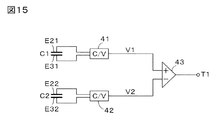
検出回路が、第1の変位電極と第1の固定電極とによって構成される第1の容量素子の静電容量値と、第2の変位電極と第2の固定電極とによって構成される第2の容量素子の静電容量値と、の差に相当する電気信号を、作用したトルクを示す電気信号として出力するようにしたものである。
(15) 本発明の第15の態様は、上述の第14の態様に係るトルクセンサにおいて、
所定回転方向のトルクの作用により環状変形体のXY平面上への正射影投影像の輪郭が円から楕円に変化する場合に、この楕円の短軸方向にV軸、長軸方向にW軸をとり、
トルクが作用していない状態において、第1の固定電極の位置が、第1の変位電極の位置に比べて、所定回転方向に所定のオフセット量だけずれ、第2の固定電極の位置が、第2の変位電極の位置に比べて、所定回転方向とは逆の方向に所定のオフセット量だけずれているようにしたものである。
(16) 本発明の第16の態様は、上述の第13の態様に係るトルクセンサにおいて、
XY平面上に、原点Oを通りX軸およびY軸に対して45°をなし、符号をもったV軸およびW軸を定義した場合に、正のV軸上に配置された第1の変位電極および第1の固定電極と、正のW軸上に配置された第2の変位電極および第2の固定電極と、負のV軸上に配置された第3の変位電極および第3の固定電極と、負のW軸上に配置された第4の変位電極および第4の固定電極と、を有し、
検出回路が、「第1の変位電極と第1の固定電極とによって構成される第1の容量素子の静電容量値と、第3の変位電極と第3の固定電極とによって構成される第3の容量素子の静電容量値と、の和」と、「第2の変位電極と第2の固定電極とによって構成される第2の容量素子の静電容量値と、第4の変位電極と第4の固定電極とによって構成される第4の容量素子の静電容量値と、の和」と、の差に相当する電気信号を、作用したトルクを示す電気信号として出力するようにしたものである。
(17) 本発明の第17の態様は、上述の第16の態様に係るトルクセンサにおいて、
所定回転方向のトルクの作用により環状変形体のXY平面上への正射影投影像の輪郭が円から楕円に変化する場合に、この楕円の短軸方向にV軸、長軸方向にW軸をとり、
トルクが作用していない状態において、第1の固定電極の位置が、第1の変位電極の位置に比べて、所定回転方向に所定のオフセット量だけずれ、第2の固定電極の位置が、第2の変位電極の位置に比べて、所定回転方向とは逆の方向に所定のオフセット量だけずれ、第3の固定電極の位置が、第3の変位電極の位置に比べて、所定回転方向に所定のオフセット量だけずれ、第4の固定電極の位置が、第4の変位電極の位置に比べて、所定回転方向とは逆の方向に所定のオフセット量だけずれているようにしたものである。
(18) 本発明の第18の態様は、上述の第14または第16の態様に係るトルクセンサにおいて、
所定回転方向のトルクが作用した結果、固定電極に対する変位電極の相対位置が変化した場合にも、容量素子を構成する一対の電極の実効対向面積が変化しないように、固定電極および変位電極のうちの一方の面積を他方の面積よりも大きく設定したものである。
(19) 本発明の第19の態様は、上述の第18の態様に係るトルクセンサにおいて、
各変位電極を、環状変形体の内周面に形成された共通導電層によって構成したものである。
(20) 本発明の第20の態様は、上述の第19の態様に係るトルクセンサにおいて、
環状変形体を導電性の弾性材料によって構成し、環状変形体の内周面自身を共通導電層として用いるようにしたものである。
(21) 本発明の第21の態様は、上述の第12の態様に係るトルクセンサにおいて、
検出対象となるトルクの作用により弾性変形を生じる材質からなり、Z軸が挿通する貫通開口部を有し、原点Oを中心としてXY平面上に、環状変形体の内側にくるように配置された内側環状変形体を更に設け、
内側環状変形体のZ軸負側の側面上に第1の内側左側接続点および第2の内側左側接続点が設けられ、
内側環状変形体のZ軸正側の側面上に第1の内側右側接続点および第2の内側右側接続点が設けられ、
第1の内側左側接続点を左側支持体に接続する第1の内側左側接続部材と、第2の内側左側接続点を左側支持体に接続する第2の内側左側接続部材と、第1の内側右側接続点を右側支持体に接続する第1の内側右側接続部材と、第2の内側右側接続点を右側支持体に接続する第2の内側右側接続部材と、
内側環状変形体の内周面もしくは外周面に固定され、内側環状変形体の弾性変形に起因した変位を生じる内側変位電極と、
内側変位電極に対向する位置に配置され、左側支持体もしくは右側支持体に固定された内側固定電極と、
を更に設け、
内側環状変形体の両側面をXY平面上に投影して正射影投影像を得た場合に、第1の内側右側接続点の投影像が正のY軸上、第2の内側右側接続点の投影像が負のY軸上、第1の内側左側接続点の投影像が正のX軸上、第2の内側左側接続点の投影像が負のX軸上に配置されており、
検出回路が、内側変位電極と内側固定電極とによって構成される容量素子の静電容量値の変動量を更に利用して、回転軸まわりのトルクを示す電気信号を出力するようにしたものである。
(22) 本発明の第22の態様は、所定の回転軸まわりのトルクを検出するトルクセンサにおいて、
検出対象となるトルクの作用により弾性変形を生じる材質からなり、回転軸が挿通する貫通開口部を有する外側環状変形体と、
検出対象となるトルクの作用により弾性変形を生じる材質からなり、回転軸が挿通する貫通開口部を有し、外側環状変形体の内側に配置された内側環状変形体と、
回転軸が左右に伸びる水平線をなすような基準観察方向から見たときに、外側環状変形体および内側環状変形体の左側に隣接する位置に配置された左側支持体と、
基準観察方向から見たときに、外側環状変形体および内側環状変形体の右側に隣接する位置に配置された右側支持体と、
外側環状変形体の左側の側面上の外側左側接続点を、左側支持体に接続する外側左側接続部材と、
外側環状変形体の右側の側面上の外側右側接続点を、右側支持体に接続する外側右側接続部材と、
内側環状変形体の左側の側面上の内側左側接続点を、左側支持体に接続する内側左側接続部材と、
内側環状変形体の右側の側面上の内側右側接続点を、右側支持体に接続する内側右側接続部材と、
外側環状変形体の内周面に固定され、外側環状変形体の弾性変形に起因した変位を生じる外側変位電極と、
外側変位電極に対向するように、内側環状変形体の外周面に固定され、内側環状変形体の弾性変形に起因した変位を生じる内側変位電極と、
外側変位電極と内側変位電極とによって構成される容量素子の静電容量値の変動量に基づいて、右側支持体および左側支持体の一方に負荷がかかった状態において他方に作用した回転軸まわりのトルクを示す電気信号を出力する検出回路と、
を設け、
回転軸に直交する投影面について、外側左側接続点の正射影投影像と外側右側接続点の正射影投影像とが異なる位置に形成され、内側左側接続点の正射影投影像と内側右側接続点の正射影投影像とが異なる位置に形成されるようにしたものである。
(23) 本発明の第23の態様は、XYZ三次元座標系におけるZ軸まわりのトルクを検出するトルクセンサにおいて、
検出対象となるトルクの作用により弾性変形を生じる材質からなり、Z軸が挿通する貫通開口部を有し、原点Oを中心としてXY平面上に配置された外側環状変形体と、
検出対象となるトルクの作用により弾性変形を生じる材質からなり、Z軸が挿通する貫通開口部を有し、原点Oを中心としてXY平面上に配置され、かつ、外側環状変形体の貫通開口部内に配置された内側環状変形体と、
外側環状変形体および内側環状変形体のZ軸負領域側に隣接する位置に配置された左側支持体と、
外側環状変形体および内側環状変形体のZ軸正領域側に隣接する位置に配置された右側支持体と、
を設け、
外側環状変形体のZ軸負側の側面上に、第1の外側左側接続点および第2の外側左側接続点が設けられ、外側環状変形体のZ軸正側の側面上に、第1の外側右側接続点および第2の外側右側接続点が設けられ、
内側環状変形体のZ軸負側の側面上に、第1の内側左側接続点および第2の内側左側接続点が設けられ、内側環状変形体のZ軸正側の側面上に、第1の内側右側接続点および第2の内側右側接続点が設けられ、
第1の外側左側接続点を左側支持体に接続する第1の外側左側接続部材と、第2の外側左側接続点を左側支持体に接続する第2の外側左側接続部材と、第1の外側右側接続点を右側支持体に接続する第1の外側右側接続部材と、第2の外側右側接続点を右側支持体に接続する第2の外側右側接続部材と、
第1の内側左側接続点を左側支持体に接続する第1の内側左側接続部材と、第2の内側左側接続点を左側支持体に接続する第2の内側左側接続部材と、第1の内側右側接続点を右側支持体に接続する第1の内側右側接続部材と、第2の内側右側接続点を右側支持体に接続する第2の内側右側接続部材と、
外側環状変形体の内周面に固定され、外側環状変形体の弾性変形に起因した変位を生じる外側変位電極と、
内側環状変形体の外周面における外測変位電極に対向する位置に固定され、内側環状変形体の弾性変形に起因した変位を生じる内側変位電極と、
外側変位電極と内側変位電極とによって構成される容量素子の静電容量値の変動量に基づいて、右側支持体および左側支持体の一方に負荷がかかった状態において他方に作用したZ軸まわりのトルクを示す電気信号を出力する検出回路と、
を更に設け、
外側環状変形体および内側環状変形体の両側面をXY平面上に投影して正射影投影像を得た場合に、第1の外側右側接続点の投影像が正のX軸上、第2の外側右側接続点の投影像が負のX軸上、第1の外側左側接続点の投影像が正のY軸上、第2の外側左側接続点の投影像が負のY軸上、第1の内側右側接続点の投影像が正のY軸上、第2の内側右側接続点の投影像が負のY軸上、第1の内側左側接続点の投影像が正のX軸上、第2の内側左側接続点の投影像が負のX軸上に配置されているようにしたものである。
(24) 本発明の第24の態様は、上述の第23の態様に係るトルクセンサにおいて、
外側環状変形体および内側環状変形体が、Z軸を中心軸として配置された円盤の中央部に、より径の小さな同心円盤の形状をした貫通開口部を形成することにより得られる円環状の部材からなるようにしたものである。
(25) 本発明の第25の態様は、上述の第24の態様に係るトルクセンサにおいて、
左側支持体および右側支持体として、中心部に貫通開口部を有する環状の構造体を用い、Z軸に沿って、左側支持体、内側環状変形体、右側支持体の各貫通開口部を貫く挿通孔が確保されるようにしたものである。
(26) 本発明の第26の態様は、上述の第24または第25の態様に係るトルクセンサにおいて、
XY平面上に、原点Oを通りX軸およびY軸に対して45°をなすV軸およびW軸を定義した場合に、V軸上に配置された第1の外側変位電極および第1の内側変位電極と、W軸上に配置された第2の外側変位電極および第2の内側変位電極と、を設け、
検出回路が、第1の外側変位電極と第1の内側変位電極とによって構成される第1の容量素子の静電容量値と、第2の外側変位電極と第2の内惻変位電極とによって構成される第2の容量素子の静電容量値と、の差に相当する電気信号を、作用したトルクを示す電気信号として出力するようにしたものである。
(27) 本発明の第27の態様は、上述の第24または第25の態様に係るトルクセンサにおいて、
XY平面上に、原点Oを通りX軸およびY軸に対して45°をなし、符号をもったV軸およびW軸を定義した場合に、正のV軸上に配置された第1の外側変位電極および第1の内側変位電極と、正のW軸上に配置された第2の外側変位電極および第2の内側変位電極と、負のV軸上に配置された第3の外側変位電極および第3の内側変位電極と、負のW軸上に配置された第4の外側変位電極および第4の内側変位電極と、を設け、
検出回路が、「第1の外側変位電極と第1の内側変位電極とによって構成される第1の容量素子の静電容量値と、第3の外側変位電極と第3の内側変位電極とによって構成される第3の容量素子の静電容量値と、の和」と、「第2の外側変位電極と第2の内側変位電極とによって構成される第2の容量素子の静電容量値と、第4の外側変位電極と第4の内側変位電極とによって構成される第4の容量素子の静電容量値と、の和」と、の差に相当する電気信号を、作用したトルクを示す電気信号として出力するようにしたものである。
(28) 本発明の第28の態様は、上述の第26または第27の態様に係るトルクセンサにおいて、
各外側変位電極を、外側環状変形体の内周面に形成された共通導電層によって構成するか、もしくは、各内側変位電極を、内側環状変形体の外周面に形成された共通導電層によって構成したものである。
(29) 本発明の第29の態様は、上述の第28の態様に係るトルクセンサにおいて、
外側環状変形体を導電性の弾性材料によって構成し、外側環状変形体の内周面自身を共通導電層として用いるようにするか、もしくは、内側環状変形体を導電性の弾性材料によって構成し、内側環状変形体の外周面自身を共通導電層として用いるようにしたものである。
(30) 本発明の第30の態様は、上述の第1~第29の態様に係るトルクセンサにおいて、
左側接続部材が、左側支持体の右側面から右方に突出した凸状部によって構成され、右側接続部材が、右側支持体の左側面から左方に突出した凸状部によって構成され、各凸状部の頂面が環状変形体の各接続点に接合されているようにしたものである。
本発明に係るトルクセンサでは、回転軸が挿通する貫通開口部を有する環状変形体を利用してトルク検出が行われる。この環状変形体の左右両脇には、左側支持体と右側支持体とが配置され、それぞれが異なる接続点に接合される。このため、一方の支持体に負荷がかかった状態で、他方の支持体にトルクが加わると、環状変形体に歪みが生じることになり、環状変形体の各部の回転軸からの距離に変化が生じる。本発明では、この距離の変化を容量素子の静電容量値によって検出できる。すなわち、環状変形体の内周面もしくは外周面に固定された変位電極と、この変位電極に対向する位置に配置され、左側支持体もしくは右側支持体に固定された固定電極と、によって構成される容量素子の静電容量値の変動量に基づいて、環状変形体の変形態様を認識することができ、作用したトルクの検出が可能になる。
環状変形体、左側支持体、右側支持体は、軸方向の厚みが小さな扁平構造体によって構成することができるので、センサ全体の軸長を短く設定することが可能になる。また、環状変形体の形状の歪みによってトルク検出が行われるので、環状変形体としては、弾性変形を生じる材質を用いる必要があるものの、比較的高い剛性をもった材質を利用しても、高精度の検出が可能になる。更に、環状変形体の形状の歪みは、一対の電極からなる容量素子によって検出できるので、構造も単純化され、コストダウンに貢献することができる。
特に、環状変形体の上下の2箇所を左側支持体に接合し、左右の2箇所を右側支持体に接合して、各接続点が90°ずつずれるようにすれば、トルクの作用によって、環状変形体を効率的に変形させることができる。環状変形体として円環状の構造体を用いると、トルクが作用していない無負荷状態では円形を維持するため、各部の回転軸からの距離は等しくなるが、トルクの作用により楕円形に変形すると、長軸位置では回転軸からの距離は伸び、短軸位置では回転軸からの距離が縮むことになる。そこで、長軸位置と短軸位置とにそれぞれ容量素子を設けておけば、同一のトルクが加わった場合、長軸位置では電極間隔が広がり静電容量値が減少するのに対して、短軸位置では電極間隔が狭まり静電容量値が増加するので、両静電容量値の差分として、作用したトルクを検出することができる。
このような差分検出は、同相ノイズやゼロ点ドリフトを抑えた安定したトルク検出に有効であり、また、温度による各部の膨張の影響を相殺して、精度の高い検出値を得るのに貢献する。更に、4組の容量素子を、長軸の両端位置および短軸の両端位置に設けるようにすれば、静電容量値が増加する2組の容量素子と、静電容量値が減少する2組の容量素子と、を用いた差分検出が可能になり、検出精度は更に向上する。
本発明に係るトルクセンサでは、環状変形体だけでなく、左側支持体および右側支持体にも、回転軸を挿通する貫通開口部を形成することが可能である。これにより、回転軸に沿って、左側支持体、環状変形体、右側支持体の各貫通開口部を貫く挿通孔を確保することができ、内部が中空となる構造を採ることができる。したがって、本発明に係るトルクセンサを、ロボットアームの関節部分に組み込んで利用する場合、この中空部分に減速機などを配置することができ、総合的に省スペースのロボットアームを設計することが可能になる。
なお、本発明に係るトルクセンサでは、トルクが作用した状態において、環状変形体のねじれ角は比較的小さく抑えることが可能であるが、それでも環状変形体の各部はトルクが加わった回転方向に移動することになる。そのため、トルクが作用すると、変位電極の位置が固定電極の位置に対してオフセットを生じることになり、容量素子を構成する一対の電極の実効対向面積に変動が生じ、この面積変動によって静電容量値に影響が及ぶことになる。
そこで、トルクが作用していない無負荷状態において、予め一方の電極を所定方向にオフセットをもたせて配置しておくようにすると、トルクが作用したときに、容量素子の実効面積の変動によって検出結果に悪影響が及ぶことを阻止することができる。あるいは、固定電極および変位電極のうちの一方の面積を他方の面積よりも大きく設定しておけば、固定電極に対する変位電極の相対位置が変化した場合にも、容量素子の実効面積を一定に維持することができ、面積変動によって検出結果に悪影響が及ぶことを阻止することができる。また、検出対象となるトルク以外の外乱成分の影響を受けない正確なトルク検出が可能になる。
本発明に係るトルクセンサでは、2組の環状変形体を組み込む構成を採ることも可能である。すなわち、外側環状変形体の内側に、更に内側環状変形体を組み込むようにすれば、2組の環状変形体のそれぞれから別個の検出結果を得ることができ、検出感度および精度を向上させることができる。また、センサ構造全体の剛性も向上する。特に、両環状変形体として円環状の構造体を用い、トルクが作用した際にいずれも楕円形に変形するようにし、一方の楕円の長軸方向が他方の楕円の短軸方向となるように、互いに90°ずらした接続点を設けるようにすれば、検出感度を更に向上させることができる。
また、外側と内側とに配置された2組の環状変形体を組み込む構成を採った場合、変位電極と固定電極とによって容量素子を構成する代わりに、外側環状変形体の内周面に形成した外側変位電極と、内側環状変形体の外周面に形成した内側変位電極と、によって容量素子を形成することも可能になる。この場合も、両環状変形体として円環状の構造体を用い、トルクが作用した際にいずれも楕円形に変形するようにし、一方の楕円の長軸方向が他方の楕円の短軸方向となるように、互いに90°ずらした接続点を設けるようにすれば、外側変位電極と内側変位電極との間の電極間隔の変動量を大きくとることができ、検出感度を更に向上させることができる。 (1) A first aspect of the present invention is a torque sensor that detects torque around a predetermined rotation axis.
An annular deformed body made of a material that is elastically deformed by the action of torque to be detected, and having a through opening through which the rotating shaft is inserted;
A left side support disposed at a position adjacent to the left side of the annular deformation body when viewed from a reference observation direction in which a rotation axis forms a horizontal line extending to the left and right;
A right support disposed at a position adjacent to the right side of the annular deformation body when viewed from the reference observation direction;
A left side connection member that connects a left side connection point on the left side surface of the annular deformation body to the left side support; and
A right connection member for connecting a right connection point on the right side surface of the annular deformation body to the right support; and
A displacement electrode fixed to the inner peripheral surface or the outer peripheral surface of the annular deformable body and causing displacement due to elastic deformation of the annular deformable body;
A fixed electrode disposed at a position facing the displacement electrode and fixed to the left support or the right support;
Based on the amount of change in the capacitance value of the capacitive element constituted by the displacement electrode and the fixed electrode, the torque around the rotation axis acting on the other of the right support and the left support in a state where a load is applied. A detection circuit that outputs an electrical signal indicating;
Provided,
The orthographic projection image of the left connection point and the orthographic projection image of the right connection point with respect to the projection plane orthogonal to the rotation axis are formed at different positions.
(2) According to a second aspect of the present invention, in the torque sensor according to the first aspect described above,
A first left connection point and a second left connection point are provided on the left side surface of the annular deformation body;
The left connection member has a first left connection member that connects the first left connection point to the left support, and a second left connection member that connects the second left connection point to the left support. ,
A first right connection point and a second right connection point are provided on the right side surface of the annular deformation body;
The right connection member includes a first right connection member that connects the first right connection point to the right support, and a second right connection member that connects the second right connection point to the right support. ,
When projecting an annular deformation body onto a projection plane orthogonal to the rotation axis to obtain an orthographic projection image, a first left connection point and a first right connection point are formed on an annular path along the contour of the annular deformation body. The orthographic projection images of the respective connection points are arranged in the order of the second left connection point and the second right connection point.
(3) According to a third aspect of the present invention, in the torque sensor according to the second aspect described above,
When two straight lines that pass through the projection point of the rotation axis and are orthogonal to each other are drawn on the projection plane orthogonal to the rotation axis, the orthographic projection images of the first left connection point and the second left connection point are the first projection images. It is arranged on a straight line, and orthographic projection images of the first right connection point and the second right connection point are arranged on the second straight line.
(4) A fourth aspect of the present invention is the torque sensor according to the first to third aspects described above,
As the left side support and right side support, an annular structure having a through opening at the center is used, and through holes are inserted through the through openings of the left side support, the annular deformation body, and the right side support along the rotation axis. Is ensured.
(5) According to a fifth aspect of the present invention, in the torque sensor according to the first to fourth aspects described above,
The annular deformable body is made of an annular member obtained by forming a through-opening in the shape of a concentric disk with a smaller diameter at the center of the disk arranged with the rotation axis as the central axis. It is.
(6) According to a sixth aspect of the present invention, in the torque sensor according to the first to fifth aspects described above,
The left side support body and the right side support body are formed of an annular member obtained by forming a through-opening in the shape of a concentric disk with a smaller diameter at the center of a disk arranged with the rotation axis as a central axis. It is what I did.
(7) A seventh aspect of the present invention is the torque sensor according to the first to sixth aspects described above,
The displacement electrode is constituted by a conductive layer formed on the inner peripheral surface of the annular deformation body,
The fixed electrode is configured by a conductive plate disposed at a position facing the conductive layer and protruding from the left support or the right support in the direction along the rotation axis.
(8) An eighth aspect of the present invention is the torque sensor according to the first to seventh aspects described above,
Of each part of the annular deformable body, when a torque in a predetermined rotation direction is applied, a first displacement electrode fixed to the first part that is displaced in a direction approaching the rotation axis, and a displacement in a direction away from the rotation axis A second displacement electrode fixed to the second portion, a first fixed electrode disposed at a position opposite to the first displacement electrode, and a second displacement electrode disposed at a position opposite to the second displacement electrode. Two fixed electrodes,
The detection circuit has a capacitance value of the first capacitive element configured by the first displacement electrode and the first fixed electrode, and a second configuration configured by the second displacement electrode and the second fixed electrode. The electric signal corresponding to the difference between the capacitance value of the capacitor element is output as an electric signal indicating the applied torque.
(9) According to a ninth aspect of the present invention, in the torque sensor according to the eighth aspect described above,
When a torque in a predetermined rotational direction is applied, the effective opposing area of the pair of electrodes constituting the capacitor element in which the electrode interval is narrowed is increased, and the effective opposing area of the pair of electrodes constituting the capacitor element in which the electrode interval is widened is decreased. As described above, the displacement electrode and the fixed electrode facing each other are arranged with an offset.
(10) According to a tenth aspect of the present invention, in the torque sensor according to the first to eighth aspects described above,
Of the fixed electrode and the displacement electrode, the effective opposing area of the pair of electrodes constituting the capacitive element does not change even when the relative position of the displacement electrode with respect to the fixed electrode changes as a result of the torque in the predetermined rotation direction. One area is set larger than the other area.
(11) An eleventh aspect of the present invention is the torque sensor according to the first to tenth aspects described above,
An inner annular deformation body that is made of a material that generates elastic deformation by the action of torque to be detected, has a through opening through which the rotation shaft is inserted, and is arranged inside the annular deformation body,
An inner left connection member for connecting an inner left connection point on the left side surface of the inner annular deformation body to the left support; and
An inner right connection member for connecting an inner right connection point on the right side surface of the inner annular deformation body to the right support; and
An inner displacement electrode fixed to the inner circumferential surface or outer circumferential surface of the inner annular deformable body and causing displacement due to elastic deformation of the inner annular deformable body;
An inner fixed electrode disposed at a position facing the inner displacement electrode and fixed to the left support or the right support;
Further provided,
The orthographic projection image of the inner left connection point and the orthographic projection image of the inner right connection point with respect to the projection plane orthogonal to the rotation axis are formed at different positions,
The detection circuit further utilizes an amount of change in the capacitance value of the capacitive element constituted by the inner displacement electrode and the inner fixed electrode, and outputs an electric signal indicating the torque around the rotation axis. .
(12) According to a twelfth aspect of the present invention, in the torque sensor according to the first aspect described above,
In order to detect the torque around the Z axis in the XYZ three-dimensional coordinate system, the annular deformation body is disposed on the XY plane with the origin O as the center, the left support body is disposed in the Z axis negative region, and the right support body is Z. Placed in the axial positive area,
A first left connection point and a second left connection point are provided on the side surface on the negative side of the Z-axis of the annular deformation body,
The left connection member has a first left connection member that connects the first left connection point to the left support, and a second left connection member that connects the second left connection point to the left support. ,
A first right connection point and a second right connection point are provided on the side surface on the positive side of the Z-axis of the annular deformation body,
The right connection member includes a first right connection member that connects the first right connection point to the right support, and a second right connection member that connects the second right connection point to the right support. ,
When projecting both side surfaces of the annular deformation body onto the XY plane to obtain an orthographic projection image, the projection image of the first right connection point is on the positive X axis, and the projection image of the second right connection point is On the negative X axis, the projection image of the first left connection point is arranged on the positive Y axis, and the projection image of the second left connection point is arranged on the negative Y axis.
(13) According to a thirteenth aspect of the present invention, in the torque sensor according to the twelfth aspect described above,
The annular deformable body is made of an annular member obtained by forming a through-opening in the shape of a concentric disk with a smaller diameter at the center of the disk arranged with the Z axis as the central axis. It is.
(14) According to a fourteenth aspect of the present invention, in the torque sensor according to the thirteenth aspect described above,
A first displacement electrode and a first fixed electrode arranged on the V-axis when the V-axis and the W-axis that define 45 ° with respect to the X-axis and the Y-axis are defined on the XY plane. And a second displacement electrode and a second fixed electrode arranged on the W axis,
The detection circuit has a capacitance value of the first capacitive element configured by the first displacement electrode and the first fixed electrode, and a second configuration configured by the second displacement electrode and the second fixed electrode. The electric signal corresponding to the difference between the capacitance value of the capacitor element is output as an electric signal indicating the applied torque.
(15) According to a fifteenth aspect of the present invention, in the torque sensor according to the fourteenth aspect described above,
When the contour of the orthogonal projection image of the annular deformation body on the XY plane changes from a circle to an ellipse by the action of torque in a predetermined rotational direction, the V axis is set in the minor axis direction of the ellipse, and the W axis is set in the major axis direction. And
In a state where no torque is applied, the position of the first fixed electrode is shifted by a predetermined offset amount in the predetermined rotation direction compared to the position of the first displacement electrode, and the position of the second fixed electrode is Compared with the position of the second displacement electrode, it is shifted by a predetermined offset amount in a direction opposite to the predetermined rotation direction.
(16) According to a sixteenth aspect of the present invention, in the torque sensor according to the thirteenth aspect described above,
The first displacement arranged on the positive V-axis when the V-axis and the W-axis having signs are defined on the XY plane through the origin O and at 45 ° with respect to the X-axis and the Y-axis. An electrode and a first fixed electrode; a second displacement electrode and a second fixed electrode arranged on the positive W axis; a third displacement electrode and a third fixed arranged on the negative V axis An electrode, and a fourth displacement electrode and a fourth fixed electrode disposed on the negative W axis,
The detection circuit is configured such that “the capacitance value of the first capacitive element constituted by the first displacement electrode and the first fixed electrode, the first displacement electrode constituted by the third displacement electrode and the third fixed electrode”. 3 ”and“ the capacitance value of the second capacitive element constituted by the second displacement electrode and the second fixed electrode, and the fourth displacement electrode ”. The electric signal corresponding to the difference between the capacitance value of the fourth capacitive element constituted by the fourth fixed electrode and the fourth fixed electrode is output as an electric signal indicating the applied torque. Is.
(17) According to a seventeenth aspect of the present invention, in the torque sensor according to the sixteenth aspect described above,
When the contour of the orthogonal projection image of the annular deformation body on the XY plane changes from a circle to an ellipse by the action of torque in a predetermined rotational direction, the V axis is set in the minor axis direction of the ellipse, and the W axis is set in the major axis direction. And
In a state where no torque is applied, the position of the first fixed electrode is shifted by a predetermined offset amount in the predetermined rotation direction compared to the position of the first displacement electrode, and the position of the second fixed electrode is Compared with the position of the second displacement electrode, the position is shifted by a predetermined offset amount in the direction opposite to the predetermined rotation direction, and the position of the third fixed electrode is in the predetermined rotation direction compared with the position of the third displacement electrode. The position of the fourth fixed electrode is shifted by a predetermined offset amount, and the position of the fourth fixed electrode is shifted by a predetermined offset amount in a direction opposite to the predetermined rotation direction compared to the position of the fourth displacement electrode. .
(18) According to an eighteenth aspect of the present invention, in the torque sensor according to the fourteenth or sixteenth aspect described above,
Of the fixed electrode and the displacement electrode, the effective opposing area of the pair of electrodes constituting the capacitive element does not change even when the relative position of the displacement electrode with respect to the fixed electrode changes as a result of the torque in the predetermined rotation direction. Is set to be larger than the other area.
(19) According to a nineteenth aspect of the present invention, in the torque sensor according to the eighteenth aspect described above,
Each displacement electrode is constituted by a common conductive layer formed on the inner peripheral surface of the annular deformable body.
(20) According to a twentieth aspect of the present invention, in the torque sensor according to the nineteenth aspect described above,
The annular deformable body is made of a conductive elastic material, and the inner peripheral surface of the annular deformable body itself is used as a common conductive layer.
(21) According to a twenty-first aspect of the present invention, in the torque sensor according to the twelfth aspect described above,
It is made of a material that is elastically deformed by the action of torque to be detected, has a through opening through which the Z axis is inserted, and is arranged on the XY plane with the origin O as the center so as to be inside the annular deformable body. An inner annular deformation body is further provided,
A first inner left side connection point and a second inner left side connection point are provided on the side surface on the Z-axis negative side of the inner annular deformable body,
A first inner right connection point and a second inner right connection point are provided on the side surface on the Z-axis positive side of the inner annular deformation body,
A first inner left connecting member that connects the first inner left connecting point to the left support, a second inner left connecting member that connects the second inner left connecting point to the left support, and a first inner A first inner right connecting member that connects the right connection point to the right support; a second inner right connecting member that connects the second inner right connection point to the right support;
An inner displacement electrode fixed to the inner circumferential surface or outer circumferential surface of the inner annular deformable body and causing displacement due to elastic deformation of the inner annular deformable body;
An inner fixed electrode disposed at a position facing the inner displacement electrode and fixed to the left support or the right support;
Further provided,
When projecting the both side surfaces of the inner annular deformation body on the XY plane to obtain an orthogonal projection image, the projection image of the first inner right connection point is on the positive Y axis and the second inner right connection point. The projected image is on the negative Y axis, the projected image of the first inner left connection point is on the positive X axis, and the projected image of the second inner left connection point is on the negative X axis;
The detection circuit further utilizes an amount of change in the capacitance value of the capacitive element constituted by the inner displacement electrode and the inner fixed electrode, and outputs an electric signal indicating the torque around the rotation axis. .
(22) According to a twenty-second aspect of the present invention, in the torque sensor for detecting the torque around the predetermined rotation axis,
An outer annular deformed body made of a material that undergoes elastic deformation by the action of torque to be detected, and having a through-opening through which the rotating shaft is inserted;
An inner annular deformation body made of a material that undergoes elastic deformation by the action of torque to be detected, having a through-opening through which the rotating shaft is inserted, and disposed inside the outer annular deformation body,
A left support disposed at a position adjacent to the left side of the outer annular deformable body and the inner annular deformable body when viewed from a reference observation direction in which a rotation axis forms a horizontal line extending in the left and right directions;
A right support disposed at a position adjacent to the right side of the outer annular deformation body and the inner annular deformation body when viewed from the reference observation direction;
An outer left side connection member for connecting an outer left side connection point on the left side surface of the outer annular deformation body to the left side support; and
An outer right side connection member for connecting an outer right side connection point on the right side surface of the outer annular deformation body to the right side support; and
An inner left side connection member for connecting an inner left side connection point on the left side surface of the inner annular deformation body to the left side support; and
An inner right connection member for connecting an inner right connection point on the right side surface of the inner annular deformation body to the right support; and
An outer displacement electrode fixed to the inner circumferential surface of the outer annular deformable body and generating displacement due to elastic deformation of the outer annular deformable body;
An inner displacement electrode fixed to the outer circumferential surface of the inner annular deformation body so as to face the outer displacement electrode, and causing displacement due to elastic deformation of the inner annular deformation body;
Based on the fluctuation amount of the capacitance value of the capacitive element constituted by the outer displacement electrode and the inner displacement electrode, the rotation axis around the rotation axis that has acted on the other of the right support and the left support is loaded. A detection circuit that outputs an electrical signal indicating torque;
Provided,
On the projection plane orthogonal to the rotation axis, the orthographic projection image of the outer left connection point and the orthographic projection image of the outer right connection point are formed at different positions, and the orthographic projection image and inner right connection point of the inner left connection point are formed. The orthogonal projection projection image is formed at a different position.
(23) According to a twenty-third aspect of the present invention, in the torque sensor for detecting torque around the Z axis in the XYZ three-dimensional coordinate system,
An outer annular deformed body made of a material that is elastically deformed by the action of torque to be detected, has a through opening through which the Z axis is inserted, and is arranged on the XY plane with the origin O as the center;
It is made of a material that is elastically deformed by the action of torque to be detected, has a through opening through which the Z-axis is inserted, is arranged on the XY plane with the origin O as the center, and in the through opening of the outer annular deformable body An inner annular deformation body arranged in
A left support disposed at a position adjacent to the Z-axis negative region side of the outer annular deformable body and the inner annular deformable body,
A right support disposed at a position adjacent to the Z-axis positive region side of the outer annular deformation body and the inner annular deformation body;
Provided,
A first outer left side connection point and a second outer left side connection point are provided on the Z-axis negative side surface of the outer annular deformation body, and the first outer left side connection point is provided on the Z-axis positive side surface of the outer annular deformation body. An outer right connection point and a second outer right connection point are provided;
A first inner left side connection point and a second inner left side connection point are provided on the Z-axis negative side surface of the inner annular deformation body, and the first annular left side connection point is provided on the Z-axis positive side surface of the inner annular deformation body. An inner right connection point and a second inner right connection point are provided;
A first outer left connecting member for connecting the first outer left connecting point to the left support, a second outer left connecting member for connecting the second outer left connecting point to the left supporting member, and a first outer A first outer right connection member for connecting the right connection point to the right support; a second outer right connection member for connecting the second outer right connection point to the right support;
A first inner left connecting member that connects the first inner left connecting point to the left support, a second inner left connecting member that connects the second inner left connecting point to the left support, and a first inner A first inner right connecting member that connects the right connection point to the right support; a second inner right connecting member that connects the second inner right connection point to the right support;
An outer displacement electrode fixed to the inner circumferential surface of the outer annular deformable body and generating displacement due to elastic deformation of the outer annular deformable body;
An inner displacement electrode that is fixed at a position facing the externally measured displacement electrode on the outer peripheral surface of the inner annular deformable body, and that causes displacement due to elastic deformation of the inner annular deformable body;
Based on the amount of change in the capacitance value of the capacitive element constituted by the outer displacement electrode and the inner displacement electrode, the Z-axis around the Z-axis that has acted on the other of the right-hand support and the left-hand support is loaded. A detection circuit that outputs an electrical signal indicating torque;
Further provided,
When the orthogonal projection image is obtained by projecting both side surfaces of the outer annular deformation body and the inner annular deformation body on the XY plane, the projection image of the first outer right connection point is on the positive X axis, the second The projection image of the outer right connection point is on the negative X axis, the projection image of the first outer left connection point is on the positive Y axis, the projection image of the second outer left connection point is on the negative Y axis, and the first The projected image of the inner right connection point is on the positive Y axis, the projected image of the second inner right connection point is on the negative Y axis, the projected image of the first inner left connection point is on the positive X axis, The projection image of the inner left
(24) According to a twenty-fourth aspect of the present invention, in the torque sensor according to the twenty-third aspect described above,
An annular member obtained by forming an outer annular deformable body and an inner annular deformable body in a central portion of a disk arranged with the Z-axis as a central axis, and having a concentric disk shape with a smaller diameter. It is made up of.
(25) According to a twenty-fifth aspect of the present invention, in the torque sensor according to the twenty-fourth aspect described above,
An annular structure having a through-opening at the center is used as the left-side support and the right-side support, and the left-side support, the inner annular deformation body, and the right-side support are inserted through the through-openings along the Z axis. A hole is secured.
(26) According to a twenty-sixth aspect of the present invention, in the torque sensor according to the twenty-fourth or twenty-fifth aspect,
When the V axis and the W axis that pass through the origin O and form 45 ° with respect to the X axis and the Y axis are defined on the XY plane, the first outer displacement electrode and the first inner electrode arranged on the V axis A displacement electrode, and a second outer displacement electrode and a second inner displacement electrode disposed on the W-axis,
The detection circuit includes a capacitance value of a first capacitive element configured by the first outer displacement electrode and the first inner displacement electrode, and a second outer displacement electrode and a second inner collar displacement electrode. An electric signal corresponding to the difference between the capacitance value of the second capacitive element to be configured is output as an electric signal indicating the applied torque.
(27) According to a twenty-seventh aspect of the present invention, in the torque sensor according to the twenty-fourth or the twenty-fifth aspect,
The first outer side arranged on the positive V-axis when the V-axis and the W-axis having signs are defined on the XY plane through the origin O and at an angle of 45 ° with respect to the X-axis and the Y-axis. Displacement electrode and first inner displacement electrode, second outer displacement electrode and second inner displacement electrode arranged on positive W axis, and third outer displacement electrode arranged on negative V axis And a third inner displacement electrode, and a fourth outer displacement electrode and a fourth inner displacement electrode disposed on the negative W axis,
The detection circuit is “by the capacitance value of the first capacitive element constituted by the first outer displacement electrode and the first inner displacement electrode, and by the third outer displacement electrode and the third inner displacement electrode. "The sum of the capacitance value of the third capacitance element configured" and "the capacitance value of the second capacitance element configured by the second outer displacement electrode and the second inner displacement electrode" The electric signal corresponding to the difference between the capacitance value of the fourth capacitive element constituted by the fourth outer displacement electrode and the fourth inner displacement electrode is shown as the applied torque. This is output as an electrical signal.
(28) According to a twenty-eighth aspect of the present invention, in the torque sensor according to the twenty-sixth or twenty-seventh aspect,
Each outer displacement electrode is constituted by a common conductive layer formed on the inner circumferential surface of the outer annular deformation body, or each inner displacement electrode is constituted by a common conductive layer formed on the outer circumferential surface of the inner annular deformation body. It is a thing.
(29) According to a twenty-ninth aspect of the present invention, in the torque sensor according to the twenty-eighth aspect,
The outer annular deformable body is made of a conductive elastic material, and the inner peripheral surface of the outer annular deformable body itself is used as a common conductive layer, or the inner annular deformable body is made of a conductive elastic material, The outer peripheral surface itself of the inner annular deformable body is used as a common conductive layer.
(30) According to a 30th aspect of the present invention, in the torque sensor according to the above 1st to 29th aspects,
The left connection member is configured by a convex portion protruding rightward from the right side surface of the left support body, and the right connection member is configured by a convex portion protruding leftward from the left side surface of the right support body. The top surface of the shape portion is joined to each connection point of the annular deformable body.
In the torque sensor according to the present invention, torque detection is performed using an annular deformable body having a through opening through which the rotating shaft is inserted. On the left and right sides of the annular deformable body, a left side support body and a right side support body are disposed, and are joined to different connection points. For this reason, if torque is applied to the other support body while a load is applied to one support body, the annular deformation body will be distorted, and the distance from the rotation axis of each part of the annular deformation body will change. Arise. In the present invention, this change in distance can be detected by the capacitance value of the capacitive element. That is, the displacement electrode is fixed to the inner peripheral surface or the outer peripheral surface of the annular deformable body, and the fixed electrode is disposed at a position facing the displacement electrode and fixed to the left support or right support. Based on the variation amount of the capacitance value of the capacitive element, the deformation mode of the annular deformable body can be recognized, and the applied torque can be detected.
Since the annular deformable body, the left side support body, and the right side support body can be configured by a flat structure having a small axial thickness, the axial length of the entire sensor can be set short. In addition, since torque detection is performed by the distortion of the shape of the annular deformable body, it is necessary to use a material that causes elastic deformation as the annular deformable body, but even if a material having relatively high rigidity is used, Accuracy can be detected. Furthermore, since the distortion of the shape of the annular deformable body can be detected by a capacitive element composed of a pair of electrodes, the structure is simplified and it is possible to contribute to cost reduction.
In particular, if the two upper and lower portions of the annular deformable body are joined to the left support, and the two left and right locations are joined to the right support so that each connection point is shifted by 90 °, the ring will be The deformable body can be efficiently deformed. When an annular structure is used as the annular deformation body, the distance from the rotation axis of each part is equal to maintain a circular shape in an unloaded state where no torque is applied. At the long axis position, the distance from the rotation axis is extended, and at the short axis position, the distance from the rotation axis is reduced. Therefore, if a capacitive element is provided at each of the long axis position and the short axis position, when the same torque is applied, the distance between the electrodes increases and the capacitance value decreases at the long axis position. Since the electrode interval is narrowed at the position and the capacitance value is increased, the applied torque can be detected as the difference between the capacitance values.
Such differential detection is effective for stable torque detection that suppresses common-mode noise and zero-point drift, and contributes to obtaining highly accurate detection values by offsetting the effects of expansion of each part due to temperature. . Further, if four sets of capacitive elements are provided at both ends of the major axis and both ends of the minor axis, two sets of capacitive elements that increase the capacitance value and two sets that decrease the capacitance value. The differential detection using the capacitive element can be performed, and the detection accuracy is further improved.
In the torque sensor according to the present invention, it is possible to form a through opening through which the rotation shaft is inserted not only in the annular deformable body but also in the left side support body and the right side support body. Thereby, along the rotation axis, it is possible to secure an insertion hole penetrating each through-opening portion of the left side support body, the annular deformation body, and the right side support body, and it is possible to adopt a structure in which the inside is hollow. Therefore, when the torque sensor according to the present invention is incorporated in a joint part of a robot arm and used, a reduction gear or the like can be arranged in the hollow part, and a space-saving robot arm can be designed comprehensively. become.
In the torque sensor according to the present invention, the torsion angle of the annular deformable body can be kept relatively small in a state where the torque is applied, but each part of the annular deformable body still moves in the rotation direction to which the torque is applied. Will do. Therefore, when torque is applied, the position of the displacement electrode is offset with respect to the position of the fixed electrode, and the effective opposing area of the pair of electrodes constituting the capacitive element is fluctuated. The value will be affected.
Therefore, if one of the electrodes is preliminarily arranged with an offset in a predetermined direction in a no-load state where no torque is applied, the detection result is detected due to a change in the effective area of the capacitive element when the torque is applied. Can be prevented from being adversely affected. Alternatively, if the area of one of the fixed electrode and the displacement electrode is set larger than the other area, the effective area of the capacitive element is maintained constant even when the relative position of the displacement electrode changes with respect to the fixed electrode. It is possible to prevent the detection result from being adversely affected by the area variation. In addition, accurate torque detection can be performed without being affected by disturbance components other than the torque to be detected.
In the torque sensor according to the present invention, it is possible to adopt a configuration in which two sets of annular deformation bodies are incorporated. That is, if the inner annular deformation body is further incorporated inside the outer annular deformation body, separate detection results can be obtained from each of the two sets of annular deformation bodies, and the detection sensitivity and accuracy can be improved. it can. Also, the rigidity of the entire sensor structure is improved. In particular, an annular structure is used as the bicyclic deformed body, and when the torque is applied, both are deformed into an elliptical shape so that the major axis direction of one ellipse becomes the minor axis direction of the other ellipse. If the connection points shifted by 90 ° are provided, the detection sensitivity can be further improved.
In addition, in the case of adopting a configuration in which two sets of annular deformation bodies arranged on the outer side and the inner side are incorporated, instead of forming a capacitive element by the displacement electrode and the fixed electrode, it is formed on the inner peripheral surface of the outer annular deformation body A capacitive element can be formed by the outer displacement electrode and the inner displacement electrode formed on the outer peripheral surface of the inner annular deformable body. In this case as well, an annular structure is used as the bicyclic deformed body so that when the torque is applied, both are deformed into an ellipse, and the major axis direction of one ellipse becomes the minor axis direction of the other ellipse. As described above, by providing connection points that are shifted by 90 ° from each other, it is possible to increase the amount of fluctuation in the electrode spacing between the outer displacement electrode and the inner displacement electrode, and it is possible to further improve the detection sensitivity.
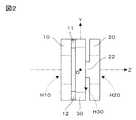
図2は、図1に示す3つの構成要素を相互に接合することにより得られるトルクセンサの基本構造部の側面図である。
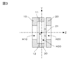
図3は、図2に示す基本構造部をYZ平面で切断した側断面図である。
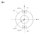
図4は、図1に示す左側支持体10および凸状部11,12を図1の右方向から見た正面図である。
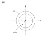
図5は、図1に示す環状変形体30を図1の右方向から見た正面図である。
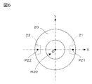
図6は、図1に示す右側支持体20および凸状部21,22を図1の右方向から見た正面図である。
図7は、図2に示す基本構造部をXY平面で切断し、図2の左方向から見た断面図である。
図8は、図2に示す基本構造部にZ軸正まわりのトルクが作用したときの変形状態を示すXY平面での断面図である(図2に示す基本構造部をXY平面で切断し、図2の左方向から見た断面図である。破線は変形前の状態を示す)。
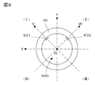
図9は、内周面に変位電極E31,E32を形成した状態の環状変形体30を、図2の左方向から見た平面図である。
図10は、固定電極E21,E22を取り付けた状態の右側支持体20を、図2の左方向から見た平面図である。
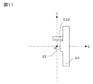
図11は、図10に示す右側支持体20の側面図である。
図12は、図3に示す基本構造部に変位電極および固定電極を付加した構造体をVZ平面で切断した側断面図である(図12の上方は、図9および図10に示すV軸方向)。
図13は、図2に示す基本構造部に上述した変位電極および固定電極を付加した構造体をXY平面で切断し、図2の左方向から見た断面図である。
図14は、図13に示す基本構造部に対して、Z軸正まわりのトルクが作用したときの状態を示す断面図である(破線は変形前の状態を示す)。
図15は、本発明の基本的な実施形態に係るトルクセンサに用いる検出回路の一例を示す回路図である。
図16は、図13に示す基本構造部に対して、Z軸正まわりのトルクが作用したときの変位電極の回転方向のずれを強調して描いた断面図である(破線は変形前の状態を示す)。
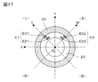
図17は、固定電極をオフセット配置した変形例に係るトルクセンサを示すXY平面での断面図である。
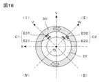
図18は、図17に示すトルクセンサについて、環状変形体30を時計まわりに若干回転させたときの各電極の位置関係を示す断面図である。
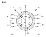
図19は、4組の容量素子を用いる変形例に係るトルクセンサのXY平面での断面図である。
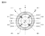
図20は、図19に示すトルクセンサについて、Z軸正まわりのトルクが作用したときの状態を示す断面図である(破線は変形前の状態を示す)。
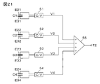
図21は、図19に示すトルクセンサに用いる検出回路の一例を示す回路図である。
図22は、固定電極に対する変位電極の相対位置が変化した場合にも、容量素子の実効面積を一定に維持する原理を示す図である。
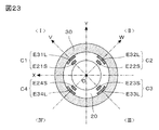
図23は、図19に示すトルクセンサに図22に示す原理を適用した変形例を示すXY平面での断面図である。
図24は、図23に示すトルクセンサをVZ平面で切断した側断面図である(図24の上方は、図23に示すV軸方向)。
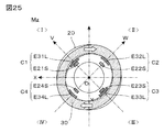
図25は、図23に示すトルクセンサについて、Z軸正まわりのモーメントMz(検出対象となるトルク)が作用したときの状態を示すXY平面での断面図である(破線は変形前の状態を示す)。
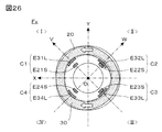
図26は、図23に示すトルクセンサについて、X軸方向の力Fxが作用したときの状態を示すXY平面での断面図である(破線は変形前の状態を示す)。
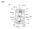
図27は、図23に示すトルクセンサについて、X軸正まわりのモーメントMxが作用したときの状態を示すZV平面での断面図である。
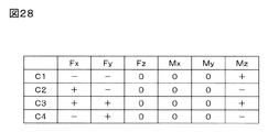
図28は、図23に示すトルクセンサについて、右側支持体20に負荷がかかった状態において、左側支持体10から環状変形体30に対して各座標軸方向の力および各座標軸まわりのモーメントが作用したときの4組の容量素子の静電容量値の変化態様を示す表である。
図29は、図23に示すトルクセンサにおいて、4組の変位電極E31L~E34Lを共通導電層E35に置き換えた変形例を示すXY平面での断面図である。
図30は、図29に示すトルクセンサにおいて、導電性材料からなる環状変形体30Aを用いることにより、環状変形体30Aの内周面を共通導電層として利用した変形例を示すXY平面での断面図である。
図31は、2組の環状変形体を用いた本発明の変形例に係るトルクセンサの基本構造部の分解斜視図である。
図32は、図31に示すトルクセンサについて、Z軸正まわりのトルクが作用したときの状態を示すXY平面での断面図である(破線は変形前の状態を示す)。
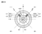
図33は、図31に示す基本構造部に、具体的な電極配置を行うことによって構成されたトルクセンサのXY平面での断面図である。
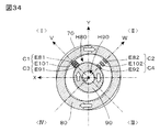
図34は、図33に示すトルクセンサについて、Z軸正まわりのトルクが作用したときの状態を示すXY平面での断面図である(破線は変形前の状態を示す)。
図35は、2組の環状変形体を用いた本発明の別な変形例に係るトルクセンサのXY平面での断面図である。
図36は、図35に示すトルクセンサについて、Z軸正まわりのトルクが作用したときの状態を示すXY平面での断面図である(破線は変形前の状態を示す)。
図37は、図35に示すトルクセンサにおいて、4組の外側変位電極E81~E84を共通導電層E85に置き換えた変形例を示すXY平面での断面図である。
図38は、図37に示すトルクセンサにおいて、導電性材料からなる環状変形体80Aを用いることにより、環状変形体80Aの内周面を共通導電層として利用した変形例を示すXY平面での断面図である。
図39は、2組の環状変形体を用いた本発明の更に別な変形例に係るトルクセンサのXY平面での断面図である。
図40は、図39に示すトルクセンサについて、右側支持体70に負荷がかかった状態において、環状変形体80,90に対してZ軸正まわりのトルク(モーメント+Mz)が作用したときの状態を示すXY平面での断面図である(破線は変形前の状態を示し、電極は図示省略。+−の符号は、当該位置の容量素子の静電容量値の増減を示す)。
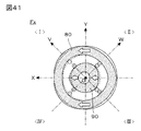
図41は、図39に示すトルクセンサについて、右側支持体70に負荷がかかった状態において、環状変形体80,90に対してX軸正方向の力+Fxが作用したときの状態を示すXY平面での断面図である(破線は変形前の状態を示し、電極は図示省略。+−の符号は、当該位置の容量素子の静電容量値の増減を示す)。
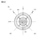
図42は、図39に示すトルクセンサについて、右側支持体70に負荷がかかった状態において、環状変形体80,90に対してY軸正方向の力+Fyが作用したときの状態を示すXY平面での断面図である(破線は変形前の状態を示し、電極は図示省略。+−の符号は、当該位置の容量素子の静電容量値の増減を示す)。
図43は、図39に示すトルクセンサについて、右側支持体70に負荷がかかった状態において、環状変形体80,90に対して各座標軸方向の力および各座標軸まわりのモーメントが作用したときの8組の容量素子の静電容量値の変化態様を示す表である。
図44は、本発明に係るトルクセンサの更に別な電極構成を示すXY平面での断面図である。 FIG. 1 is an exploded perspective view of a basic structure portion of a torque sensor according to a basic embodiment of the present invention.
FIG. 2 is a side view of the basic structure of the torque sensor obtained by joining the three components shown in FIG. 1 to each other.
FIG. 3 is a side sectional view of the basic structure shown in FIG. 2 cut along the YZ plane.
4 is a front view of the
FIG. 5 is a front view of the
6 is a front view of the
FIG. 7 is a cross-sectional view of the basic structure shown in FIG. 2 taken along the XY plane and viewed from the left in FIG.
FIG. 8 is a cross-sectional view in the XY plane showing a deformation state when a torque around the Z-axis is applied to the basic structure shown in FIG. 2 (the basic structure shown in FIG. 2 is cut along the XY plane, It is sectional drawing seen from the left direction of FIG 2. The broken line shows the state before a deformation | transformation.
FIG. 9 is a plan view of the
10 is a plan view of the
FIG. 11 is a side view of the
12 is a side sectional view of the basic structure shown in FIG. 3 in which a displacement electrode and a fixed electrode are added, cut along the VZ plane (the upper part of FIG. 12 is the direction of the V-axis shown in FIGS. 9 and 10). ).
FIG. 13 is a cross-sectional view of the basic structure shown in FIG. 2 in which the above-described displacement electrode and fixed electrode are added, cut along the XY plane and viewed from the left in FIG.
FIG. 14 is a cross-sectional view showing a state when a torque around the Z-axis is applied to the basic structure shown in FIG. 13 (the broken line shows a state before deformation).
FIG. 15 is a circuit diagram showing an example of a detection circuit used in the torque sensor according to the basic embodiment of the present invention.
FIG. 16 is a cross-sectional view that emphasizes the displacement of the displacement electrode in the rotation direction when a torque around the Z-axis is applied to the basic structure shown in FIG. 13 (the broken line is the state before deformation). Showing).
FIG. 17 is a cross-sectional view on the XY plane showing a torque sensor according to a modified example in which the fixed electrodes are offset.
18 is a cross-sectional view showing the positional relationship of the electrodes when the
FIG. 19 is a cross-sectional view in the XY plane of a torque sensor according to a modification using four sets of capacitive elements.
FIG. 20 is a cross-sectional view showing a state when torque around the Z-axis is acting on the torque sensor shown in FIG. 19 (the broken line shows a state before deformation).
FIG. 21 is a circuit diagram showing an example of a detection circuit used in the torque sensor shown in FIG.
FIG. 22 is a diagram illustrating the principle of maintaining the effective area of the capacitive element constant even when the relative position of the displacement electrode with respect to the fixed electrode changes.
23 is a cross-sectional view on the XY plane showing a modification in which the principle shown in FIG. 22 is applied to the torque sensor shown in FIG.
24 is a side sectional view of the torque sensor shown in FIG. 23 taken along the VZ plane (the upper part of FIG. 24 is the V-axis direction shown in FIG. 23).
FIG. 25 is a cross-sectional view on the XY plane showing a state when a moment Mz (a torque to be detected) about the positive Z axis acts on the torque sensor shown in FIG. 23 (broken lines indicate the state before deformation). Show).
FIG. 26 is a cross-sectional view on the XY plane showing a state when the force Fx in the X-axis direction is applied to the torque sensor shown in FIG. 23 (a broken line shows a state before deformation).
FIG. 27 is a cross-sectional view on the ZV plane showing a state when a moment Mx about the positive X axis acts on the torque sensor shown in FIG.
FIG. 28 shows the torque sensor shown in FIG. 23 in which a force in the direction of each coordinate axis and a moment around each coordinate axis acted on the
FIG. 29 is a cross-sectional view on the XY plane showing a modification in which the four pairs of displacement electrodes E31L to E34L are replaced with the common conductive layer E35 in the torque sensor shown in FIG.
FIG. 30 is a cross-sectional view in the XY plane showing a modification in which the inner peripheral surface of the
FIG. 31 is an exploded perspective view of a basic structure portion of a torque sensor according to a modification of the present invention using two sets of annular deformation bodies.
FIG. 32 is a cross-sectional view of the torque sensor shown in FIG. 31 on the XY plane showing a state when a torque around the Z-axis is applied (the broken line shows a state before deformation).
FIG. 33 is a cross-sectional view in the XY plane of a torque sensor configured by performing a specific electrode arrangement on the basic structure shown in FIG.
FIG. 34 is a cross-sectional view on the XY plane showing a state when a torque around the Z-axis is applied to the torque sensor shown in FIG. 33 (the broken line shows a state before deformation).
FIG. 35 is a cross-sectional view in the XY plane of a torque sensor according to another modification of the present invention using two sets of annular deformation bodies.
FIG. 36 is a cross-sectional view on the XY plane showing a state when a torque around the Z-axis is applied to the torque sensor shown in FIG. 35 (the broken line shows a state before deformation).
FIG. 37 is a cross-sectional view on the XY plane showing a modification in which the four sets of outer displacement electrodes E81 to E84 are replaced with a common conductive layer E85 in the torque sensor shown in FIG.
FIG. 38 is a cross-sectional view in the XY plane showing a modification in which the inner peripheral surface of the
FIG. 39 is a cross-sectional view in the XY plane of a torque sensor according to still another modified example of the present invention using two sets of annular deformable bodies.
FIG. 40 shows a state of the torque sensor shown in FIG. 39 when a torque (moment + Mz) around the Z-axis is applied to the annular
FIG. 41 is an XY plane showing a state when a force + Fx in the positive direction of the X axis is applied to the annular
FIG. 42 is an XY plane showing a state when a force + Fy in the Y-axis positive direction is applied to the annular
FIG. 43 shows the torque sensor shown in FIG. 39 when the force on each coordinate axis and the moment around each coordinate axis are applied to the annular
FIG. 44 is a sectional view on the XY plane showing still another electrode configuration of the torque sensor according to the present invention.
<<< §1. 本発明に係るトルクセンサの基本構造部 >>>
図1は、本発明の基本的な実施形態に係るトルクセンサの基本構造部の分解斜視図である。図示のように、この基本構造部は、左側支持体10と右側支持体20との間に、環状変形体30を配置し、これら3つの構成要素を相互に接合することによって構成される。ここでは、便宜上、図示のとおりXYZ三次元座標系を定義して、以下の説明を行うことにする。ここで、図の水平方向に描かれたZ軸が、検出対象となるトルクの回転軸に相当し、このトルクセンサは、この回転軸まわり(Z軸まわり)のトルクを検出する機能を果たすことになる。
図の中央に配置された環状変形体30は、検出対象となるトルクの作用により弾性変形を生じる材質からなり、その内部には、回転軸(Z軸)が挿通する貫通開口部H30が形成されている。一方、図の左側に配置された左側支持体10は、環状変形体30の左側面を支持する部材であり、図の右側に配置された右側支持体20は、環状変形体30の右側面を支持する部材である。ここに示す基本的な実施形態の場合、左側支持体10は、回転軸(Z軸)が挿通する貫通開口部H10が形成された環状部材であり、右側支持体20は、回転軸(Z軸)が挿通する貫通開口部H20が形成された環状部材である。
なお、一般に右側および左側という概念は、特定の観察方向から見た場合にのみ意味をもつ概念であるが、ここでは説明の便宜上、図1に示すとおり、回転軸(Z軸)が左右に伸びる水平線をなすような基準観察方向(右方向がZ軸の正方向となるような観察方向)から見たときに、環状変形体30の左側に隣接する位置に配置された支持体を左側支持体10と呼び、環状変形体30の右側に隣接する位置に配置された支持体を右側支持体20と呼ぶことにする。
ここでは、環状変形体30の中心位置にXYZ三次元座標系の原点Oを定義しており、左側支持体10,環状変形体30,右側支持体20は、いずれもZ軸を中心軸とする円環状の部材によって構成されている。より具体的には、環状変形体30は、Z軸(回転軸)を中心軸として配置された円盤の中央部に、より径の小さな同心円盤の形状をした貫通開口部H30を形成することにより得られる円環状の部材からなる。同様に、左側支持体10および右側支持体20も、Z軸(回転軸)を中心軸として配置された円盤の中央部に、より径の小さな同心円盤の形状をした貫通開口部H10,H20を形成することにより得られる円環状の部材からなる。
一方、左側支持体10の右側面には、右方に突出した2つの扇形の凸状部11,12が設けられており、この凸状部11,12の頂面が環状変形体30の左側面に接合されている。図示のとおり、凸状部11は環状変形体30の上部(Y軸正方向に位置する部分)に接合され、凸状部12は環状変形体30の下部(Y軸負方向に位置する部分)に接合される。同様に、右側支持体20の左側面には、左方に突出した2つの扇形の凸状部21,22が設けられており、この凸状部21,22の頂面が環状変形体30の右側面に接合されている。図示のとおり、凸状部21は環状変形体30の奥の部分(X軸正方向に位置する部分)に接合され、凸状部22は環状変形体30の手前の部分(X軸負方向に位置する部分)に接合される。
図2は、図1に示す3つの構成要素を相互に接合することにより得られるトルクセンサの基本構造部の側面図であり、図3は、この基本構造部をYZ平面で切断した側断面図である。ここに示す例の場合、図3に示すとおり、凸状部11,12は、左側支持体10と一体となった構造体であり、その頂面が環状変形体30の左側面に接合されている。同様に、凸状部21,22は、右側支持体20と一体となった構造体であり、その頂面が環状変形体30の右側面に接合されている。
結局、凸状部11,12は、環状変形体30の左側支持体10に対向する左側の側面上の左側接続点を、左側支持体10に接続する左側接続部材として機能し、凸状部21,22は、環状変形体30の右側支持体20に対向する右側の側面上の右側接続点を、右側支持体20に接続する右側接続部材として機能する。
図4は、左側支持体10および凸状部11,12を図1の右方向から見た正面図、図5は、環状変形体30を図1の右方向から見た正面図、図6は、右側支持体20および凸状部21,22を図1の右方向から見た正面図である。図4において、凸状部11,12の中心位置に示されている点P11,P12は左側接続点であり、§2において、環状変形体30に対する接続位置を説明するために用いられる。同様に、図6において、凸状部21,22の中心位置に示されている点P21,P22は右側接続点であり、やはり§2において、環状変形体30に対する接続位置を説明するために用いられる。
なお、図4に示す部品(左側支持体10および凸状部11,12)と図6に示す部品(右側支持体20および凸状部21,22)とは、実際には、全く同一のものにするのが好ましい。この場合、図4に示す部品をY軸を回転軸として180°回転させて裏返し、更に、Z軸を回転軸として90°回転させれば、図6に示す部品に完全に一致する。したがって、実際には、図4に示す部品を2組用意し、図5に示す部品を1組用意すれば、図2に示す基本構造部を構成することができる。
図5に示すとおり、環状変形体30には、円形の貫通開口部H30が設けられているが、これは、検出に必要な弾性変形を生じさせるためのものである。後述するように、この基本構造部に検出対象となるトルクが作用した場合、環状変形体30は楕円形に変形する必要がある。このような環状変形体30の弾性変形のしやすさは、センサの検出感度を左右するパラメータになる。弾性変形しやすい環状変形体30を用いれば、微小なトルクでも検出可能な感度の高いセンサを実現することができるが、検出可能なトルクの最大値は抑制されることになる。逆に、弾性変形しにくい環状変形体30を用いれば、検出可能なトルクの最大値を大きくとることができるが、感度は低下するため、微小なトルクの検出はできなくなる。
環状変形体30の弾性変形のしやすさは、Z軸方向の厚み(薄くするほど弾性変形しやすい)および貫通開口部H30の径(大きくするほど弾性変形しやすい)に依存して決まり、更に、その材質にも依存して決まる。したがって、実用上は、トルクセンサの用途に応じて、環状変形体30の各部の寸法や材質を適宜選択すればよい。
一方、左側支持体10および右側支持体20は、本発明の検出原理上、弾性変形を生じる部材である必要はない。むしろ、作用したトルクが環状変形体30の変形に100%寄与するようにするためには、左側支持体10および右側支持体20は、完全な剛体である方が好ましい。図示の例において、左側支持体10および右側支持体20として、中心部に貫通開口部H10,H20を有する環状の構造体を用いた理由は、弾性変形しやすくするためではなく、回転軸(Z軸)に沿って、左側支持体10、環状変形体30、右側支持体20の各貫通開口部H10,H30,H20を貫く挿通孔が確保されるようにするためである。
図3の側断面図を見れば明らかなように、この基本構造部は、内部が中空となる構造を採っている。このような中空部分を有するトルクセンサを、ロボットアームの関節部分に組み込んで利用する場合、この中空部分に減速機などを配置することができ、総合的に省スペースのロボットアームを設計することが可能になる。これは、中実丸棒形状をしたトーションバーのねじれを利用する従来型のトルクセンサでは実現困難であった利点のひとつである。
このように、本発明に係るトルクセンサでは、環状変形体30は、トルク検出に必要な程度の弾性変形を生じる材質で構成する必要があるが、左側支持体10および右側支持体20は、弾性変形を生じる必要はなく、むしろ剛性の高い材質を用いて構成するのが好ましい。実用上、左側支持体10,右側支持体20,環状変形体30の材料としては、絶縁材料を利用するのであれば、プラスチックなどの合成樹脂を用いれば十分であり、導電材料を利用するのであれば(この場合、後述するように、電極が短絡しないよう必要箇所に絶縁を施す必要がある)、ステンレス、アルミニウムなどの金属を用いれば十分である。もちろん、絶縁材料と導電材料とを組み合わせて利用してもかまわない。
左側支持体10、右側支持体20、環状変形体30は、いずれも軸方向の厚みが小さな扁平構造体によって構成することができるので、センサ全体の軸長を短く設定することが可能になる。また、環状変形体30の形状の歪みによってトルク検出が行われるので、環状変形体30としては、弾性変形を生じる材質を用いる必要があるものの、比較的高い剛性をもった材質を利用しても、高精度の検出が可能になる。
<<< §2. 本発明におけるトルクの検出原理 >>>
続いて、ここでは、§1で述べた基本構造部にトルクが作用した場合、各部がどのように変形するかを考えてみる。図7は、図2に示す基本構造部をXY平面で切断し、図2の左方向から見た断面図である。なお、この図7に示されたXY座標系は、通常のXY座標系を裏側から見たものになる(X軸正方向は図の左方向になる)。したがって、このXY座標系では、左上領域が第1象限、右上領域が第2象限、右下領域が第3象限、左下領域が第4象限になる。図示のI~IVは、この座標系の各象限を示すものである。図にハッチングを施した断面部分は、環状変形体30の部分に相当し、その奥に、右側支持体20が見えている。図の点P11~P22は、図4および図6に示した各接続点P11~P22のXY平面上への正射影投影像である。
すなわち、図7において、Y軸上に配置された点P11,P12は、左側支持体10の凸状部11,12の接合位置(接合面の中心点)を示しており、X軸上に配置された点P21,P22は、右側支持体20の凸状部21,22の接合位置(接合面の中心点)を示している。結局、環状変形体30の左側面は、Y軸に沿った2箇所の接続点P11,P12において左側支持体10に接合され、環状変形体30の右側面は、X軸に沿った2箇所の接続点P21,P22において右側支持体20に接合されていることになる。
このように、環状変形体30の上下の2箇所を左側支持体10に接合し、左右の2箇所を右側支持体20に接合して、各接続点が90°ずつずれるようにすれば、トルクの作用によって、環状変形体30を効率的に変形させることができる。
図7に示す例の場合、環状変形体30の両側面をXY平面上に投影して正射影投影像を得た場合に、第1の右側接続点P21の投影像が正のX軸上、第2の右側接続点P22の投影像が負のX軸上、第1の左側接続点P11の投影像が正のY軸上、第2の左側接続点P12の投影像が負のY軸上に配置されていることになる。このような配置を行うと、環状変形体30を軸対称性をもった楕円に変形させることができるので、軸対称性をもった検出値を得ることができる。
本発明に係るトルクセンサは、図2に示す基本構造部において、左側支持体10と右側支持体20との間に相対的に加わるトルク(回転モーメント)を検出するものであり、検出値は、両支持体10,20間に相対的に作用する力を示すものである。そこで、ここでは説明の便宜上、右側支持体20に負荷がかかった状態において、左側支持体10に加わった回転モーメントを検出対象となるトルクとして考えることにする(もちろん、左側支持体10に負荷がかかった状態において、右側支持体20に加わった回転モーメントを検出対象となるトルクとしても等価である。)。
たとえば、ロボットアームの関節部分にこのトルクセンサを利用した一例として、左側支持体10にモータなどの駆動源を取り付け、右側支持体20にロボットハンドを取り付けた例を考えてみよう。ロボットハンドに重量のある物体が把持されている状態で、駆動源から左側支持体10に対して回転駆動力を加えたとすると、この回転駆動力が関節部分を構成する基本構造部を介して、ロボットハンド側へと伝達されることになる。この場合、右側支持体20を回転駆動させようとするトルクが作用することになり、当該トルクは、右側支持体20を固定した状態において、左側支持体10に加わった回転モーメントに相当する。
さて、このような回転モーメントが、図7に示す構造体にどのような変化をもたらすかを考えてみる。右側支持体20を固定すると、図7に示すX軸上の接続点P21,P22の位置は固定状態となる。一方、左側支持体10に対して、たとえば、図7において時計まわりの方向に回転モーメントが加わったとすると、Y軸上の接続点P11,P12は時計まわりに移動しようとする。そうなると、必然的に、第1象限Iに位置する円弧P21−P11の部分は内側方向に縮み、第2象限IIに位置する円弧P11−P22の部分は外側に膨らみ、第3象限IIIに位置する円弧P22−P12の部分は内側方向に縮み、第4象限IVに位置する円弧P12−P21の部分は外側に膨らむことになる。
図8は、図7に示す構造体に、このような変形が生じた状態を示す断面図である。すなわち、図2に示す基本構造部にZ軸正まわりのトルクが作用した場合に、この基本構造部をXY平面で切断し、図2の左方向から見た断面図である。なお、本願では、任意の座標軸に関して、右ねじを当該座標軸の正方向に進めるための回転方向を正方向と定義し、右ねじを当該座標軸の負方向に進めるための回転方向を負方向と定義している。したがって、図8において、Z軸正まわりのトルクは、図に白抜き矢印で示すとおり時計まわりの方向に作用するトルクということになる。
図8に描かれた破線は、環状変形体30の変形前の状態(図7の状態)を示している。この破線を参考にすれば、Z軸正まわりのトルクが作用したことにより、環状変形体30は楕円形に変形していることが容易に把握できよう。ここでは、説明の便宜上、XY平面上に、原点Oを通りX軸およびY軸に対して45°をなすV軸およびW軸を定義する。V軸は第1象限Iを正方向とする座標軸であり、W軸は第2象限IIを正方向とする座標軸である。図示のとおり、環状変形体30は、V軸を短軸方向、W軸を長軸方向とする楕円に変形しており、V軸およびW軸に対して軸対称性を有している。このような軸対称性は、§3で述べる方法でトルクの検出値を得る場合に好都合である。
図示の実施形態において、軸対称性をもった変形が生じるのは、図7に示すとおり、無負荷時(トルクが作用していない時)に環状変形体30が完全な円形をしており、環状変形体30の両側面をXY平面上に投影して正射影投影像を得た場合に、第1の右側接続点P21の投影像が正のX軸上、第2の右側接続点P22の投影像が負のX軸上、第1の左側接続点P11の投影像が正のY軸上、第2の左側接続点P12の投影像が負のY軸上に配置されているためである。
作用したトルクが大きければ大きいほど、環状変形体30はより扁平した楕円に変形することになる。したがって、図8において、環状変形体30のV軸上に位置する部分の原点Oからの距離や、環状変形体30のW軸上に位置する部分の原点Oからの距離を測定することができれば(これらの距離は、破線で示す変形前の位置からの変位量を示す情報になる)、作用したトルクの大きさを求めることができる。別言すれば、環状変形体30の内周面もしくは外周面の径方向の変位を測定することができればよい。
一方、逆向きにトルクが作用した場合、すなわち、Z軸負まわりのトルクが作用した場合は、図8に示す例とは逆に、環状変形体30(の接続点P11,P12)に対して反時計まわりの回転力が作用するため、環状変形体30は、V軸を長軸方向、W軸を短軸方向とする楕円に変形する。したがって、環状変形体30のV軸上に位置する部分あるいはW軸上に位置する部分の変位方向は、図8に示す例とは逆の方向になる。
結局、環状変形体30のV軸上に位置する部分あるいはW軸上に位置する部分の変位を測定すれば、作用したトルクの方向および大きさの双方を検出することが可能になる。たとえば、環状変形体30の内周面とV軸との交点の位置をモニタした場合、破線で示す基準位置から内側方向に変位した場合はZ軸正まわりのトルクが加わっており、外側方向に変位した場合はZ軸負まわりのトルクが加わっていると判断できる。あるいは、環状変形体30の内周面とW軸との交点の位置をモニタした場合、破線で示す基準位置から外側方向に変位した場合はZ軸正まわりのトルクが加わっており、内側方向に変位した場合はZ軸負まわりのトルクが加わっていると判断できる。もちろん、変位量の絶対値は、作用したトルクの大きさを示すものになる。
本発明に係るトルクセンサにおいて生じる環状変形体30の径方向の変位は、環状変形体30に生じたねじれ角度が小さくても、環状変形体の径次第で比較的大きな変位になる。このため、比較的剛性が高い環状変形体30を用いたとしても、十分な感度をもったトルク検出が可能になる。
以上が、本発明におけるトルクの検出原理である。本発明では、このような原理に基づくトルク検出を行うために、これまで述べてきた基本構造部に、更に、容量素子と検出回路とを付加することになる。
<<< §3. 容量素子と検出回路 >>>
上述したとおり、本発明では、図2に示す基本構造部に、更に、容量素子と検出回路を付加し、トルクセンサを構成することになる。図8に示すように、トルクの作用により、環状変形体30は楕円に変形する。このような変形により、最も大きな変位を生じる部分は、V軸上に位置する部分あるいはW軸上に位置する部分であるから、環状変形体30の特定部分の変位に基づいて、環状変形体30の変形量(作用したトルクの大きさ)を測定するには、V軸上に位置する部分あるいはW軸上に位置する部分の変位を測定するのが最も効率的である。
そこで、ここで述べる実施形態では、環状変形体30の内周面のV軸上に位置する部分およびW軸上に位置する部分に変位電極を形成している。図9は、内周面に変位電極E31,E32を形成した状態の環状変形体30を、図2の左方向から見た平面図である。説明の便宜上、X,Y,V,W軸が重ねて描かれている。変位電極E31は、V軸の正の領域と環状変形体30の内周面との交差位置に形成された電極であり、変位電極E32は、W軸の正の領域と環状変形体30の内周面との交差位置に形成された電極である。これら変位電極E31,E32の奥行き寸法(図9の紙面に垂直方向の寸法)は、環状変形体30の奥行き寸法に等しい。この例の場合、変位電極E31,E32は、環状変形体30の内周面に、蒸着やメッキ等の方法で形成された金属膜などの導電層によって構成されている。もちろん、環状変形体30がアルミニウムやステンレスのような金属でできている場合は、環状変形体30自体が導電性をもつため、絶縁層を介して変位電極E31,E32を形成する必要がある。
一方、これら変位電極E31,E32に対向する位置には、それぞれ固定電極E21,E22が設けられ、右側支持体20に固定される。図10は、これら固定電極E21,E22を取り付けた状態の右側支持体20を、図2の左方向から見た平面図である。ここでも、説明の便宜上、X,Y,V,W軸が重ねて描かれている。固定電極E21は、V軸の正の領域に配置され、変位電極E31に対向する。固定電極E22は、W軸の正の領域に配置され、変位電極E32に対向する。
図11は、図10に示す右側支持体20の側面図である。図示のとおり、固定電極E22は、右側支持体20の左側面から回転軸に沿った方向(Z軸負方向)に突き出した導電板によって構成されている。なお、固定電極E21は、固定電極E22の奥に隠れているため、図11には現れていない。
図12は、図3に示す基本構造部に変位電極および固定電極を付加した構造体をVZ平面で切断した側断面図である。図3がYZ平面で切断した側断面図であるのに対して、図12はVZ平面で切断した側断面図であるため、図12の上方は、Y軸方向ではなく、図9および図10に示すV軸方向となっている。この図12の側断面図には、V軸上に配置された変位電極E31と固定電極E21とが互いに対向している状態が明瞭に示されている。変位電極E31は、環状変形体30の内周面に固着された電極であるため、環状変形体30の変形に依存して変位する。一方、固定電極E21は、右端が右側支持体20に固定されており、環状変形体30の変形にかかわらず、常に一定の位置を保つことになる。
結局、変位電極E31の固定電極E21に対する相対位置は、環状変形体30の変形に依存して変化することになる。別言すれば、変位電極E31と固定電極E21との電極間距離は、環状変形体30の変形に依存して変化する。図12には示されていないが、W軸上に配置された変位電極E32と固定電極E22との関係も全く同様である。
図13は、図2に示す基本構造部に上述した変位電極および固定電極を付加した構造体をXY平面で切断し、図2の左方向から見た断面図である。この断面図では、V軸上に配置された変位電極E31と固定電極E21とが互いに対向し、W軸上に配置された変位電極E32と固定電極E22とが互いに対向した状態が明瞭に示されている。
ここに示す実施形態の場合、変位電極E31,E32は、環状変形体30の内周面に形成された導電層によって構成されているため、その表面は環状変形体30の内周に沿った曲面になる。そこで、これらに対向する固定電極E21,E22も、曲面状の電極にしている。別言すれば、変位電極E31,E32や固定電極E21,E22の表面は、Z軸を中心軸とした同心状の円柱表面によって構成されている。もっとも、各電極の表面形状は容量素子を構成する役割を果たすことができれば、どのような形状であってもよいので、表面が平面となる平板状の電極を用いてもかまわない。
なお、本願図面では、図示の便宜上、各変位電極および各固定電極の厚みの実寸を無視して描いてある。たとえば、変位電極E31,E32を、環状変形体30の内周面に形成された導電層(蒸着層やメッキ層)によって構成した場合、その厚みは、数μm程度に設定することができる、これに対して、固定電極E21,E22を、右側支持体20の左側面から突き出した導電板(金属板)によって構成した場合、実用上の強度を確保するために、その厚みは、数mm程度確保するのが好ましい。したがって、図13等では、便宜上、変位電極の厚みと固定電極の厚みを同じ寸法で描いてあるが、これら電極の厚みの実寸は、製造工程や実用上の強度を考慮して、それぞれ適当な値に設定されるべきものである。
図14は、図13に示す基本構造部に対して、Z軸正まわりのトルクが作用したときの状態を示すXY断面図である。§2で述べたとおり、このようなトルクが作用すると、環状変形体30は楕円状に変形し、V軸は当該楕円の短軸方向、W軸は当該楕円の長軸方向になる。その結果、V軸上に配置された一対の電極E21,E31の電極間隔は狭まり、W軸上に配置された一対の電極E22,E32の電極間隔は広がることになる。そこで、一対の電極E21,E31により容量素子C1を構成し、一対の電極E22,E32により容量素子C2を構成しておけば、これら容量素子C1,C2の静電容量値の変動量として、作用したトルクの方向および大きさを検出することが可能になる。
たとえば、図13に示す無負荷状態(トルクが作用していない状態)を基準として、電極E21,E31からなる容量素子C1の静電容量値の変動に着目すると、図14に示すようにZ軸正まわりのトルクが作用すると、電極間隔が狭まるため、静電容量値は増加することになり、逆に、Z軸負まわりのトルクが作用すると、電極間隔が広がるため、静電容量値は減少することになる。したがって、静電容量値の増加変動はZ軸正まわりのトルクが作用していることを示し、静電容量値の減少変動はZ軸負まわりのトルクが作用していることを示すことになる。もちろん、変動量の絶対値は、作用したトルクの大きさを示すことになる。
同様に、電極E22,E32からなる容量素子C2の静電容量値の変動に着目すると、図14に示すようにZ軸正まわりのトルクが作用すると、電極間隔が広がるため、静電容量値は減少することになり、逆に、Z軸負まわりのトルクが作用すると、電極間隔が狭まるため、静電容量値は増加することになる。したがって、静電容量値の減少変動はZ軸正まわりのトルクが作用していることを示し、静電容量値の増加変動はZ軸負まわりのトルクが作用していることを示すことになる。もちろん、変動量の絶対値は、作用したトルクの大きさを示すことになる。
結局、容量素子C1を用いても、容量素子C2を用いても、Z軸まわりのトルク検出が可能であり、理論的には、いずれか一方の容量素子のみを用いれば足りる。ただ、実用上は、容量素子C1,C2の双方を用いた検出を行うのが好ましい。すなわち、環状変形部30が楕円に変形した際の短軸位置(V軸上)と長軸位置(W軸上)とにそれぞれ容量素子C1,C2を設けておけば、同一のトルクが加わった場合、短軸位置(V軸上)では電極間隔が狭まり静電容量値が増加するのに対して、長軸位置(W軸上)では電極間隔が広がり静電容量値が減少するので、両静電容量値C1,C2の差分として、作用したトルクを検出することができる。このような差分検出は、同相ノイズやゼロ点ドリフトを抑えた安定したトルク検出に有効であり、また、温度による各部の膨張の影響を相殺して、精度の高い検出値を得るのに貢献する。
このような差分検出を行うためには、要するに、環状変形体30の各部分のうち、所定回転方向のトルクが作用したときに、回転軸に近づく方向に変位する第1の部分(この例ではV軸との交差部分)に固定された第1の変位電極E31と、回転軸から離れる方向に変位する第2の部分(この例ではW軸との交差部分)に固定された第2の変位電極E32と、第1の変位電極E31に対向する位置に配置された第1の固定電極E21と、第2の変位電極E32に対向する位置に配置された第2の固定電極E22と、を設けておけばよい。
そして、このような差分検出を行うための検出回路として、第1の変位電極E31と第1の固定電極E21とによって構成される第1の容量素子C1の静電容量値と、第2の変位電極E32と第2の固定電極E22とによって構成される第2の容量素子C2の静電容量値と、の差に相当する電気信号を、作用したトルクを示す電気信号として出力する回路を設けておけばよい。
図15は、このような差分検出を行う機能をもった検出回路の一例を示す回路図である。この回路図に示すE21,E31,E22,E32は、図13および図14に示す各電極であり、C1,C2は、これらの電極によって構成される容量素子である。C/V変換回路41,42は、それぞれ容量素子C1,C2の静電容量値を電圧値V1,V2に変換する回路であり、変換後の電圧値V1,V2は、それぞれ各静電容量値に対応した値になる。差分演算器43は、電圧値の差分「V1−V2」を求め、これを出力端子T1に出力する機能を有する。
図13に示す例において、変位電極E31,E32を同一形状、同一サイズの電極によって構成し、固定電極E21,E22を同一形状、同一サイズの電極によって構成し、V軸に対する電極E31,E21の位置関係と、W軸に対する電極E32,E22の位置関係と、が同一になるように設定すれば、図13に示す無負荷状態において、容量素子C1,C2の静電容量値は等しくなる。したがって、図15に示す検出回路から出力端子T1に出力される電圧値は0になる。
これに対して、図14に示す例のように、Z軸正まわりのトルクが作用すると、容量素子C1の静電容量値は大きくなり、容量素子C2の静電容量値は小さくなるので、図15に示す検出回路から出力端子T1に出力される電圧値は正の値となり、トルクが大きいほどその絶対値は大きくなる。逆に、Z軸負まわりのトルクが作用すると、容量素子C1の静電容量値は小さくなり、容量素子C2の静電容量値は大きくなるので、図15に示す検出回路から出力端子T1に出力される電圧値は負の値となり、トルクが大きいほどその絶対値は大きくなる。かくして、出力端子T1には、符号を含めたトルクの検出値が得られる。
なお、ここに示す実施形態では、各固定電極E21,E22を、右側支持体20に固定しているが、固定電極は左側支持体10に固定してもかまわない。たとえば、図12に示す例の場合、固定電極E21は、右側支持体20の左側面から左側へ突き出した導電板によって構成されているが、左側支持体10の右側面から右側へ突き出した導電板によって固定電極E21を構成してもかまわない。要するに、固定電極E21は、変位電極E31に対向する定位置に、環状変形体30の変形にかかわらず維持されるように設けられていればよい。
また、ここに示す実施形態では、変位電極E31,E32を、環状変形体30の内周面に固定しているが、変位電極は、環状変形体30の外周面に固定してもかまわない。図14を見れば明らかなように、環状変形体30が楕円に変形した際に変位を生じるのは、環状変形体30の内周面だけではなく、外周面も同じように変位を生じる。したがって、変位電極は環状変形体30の外周面に形成してもよい。この場合、変位電極に対向する固定電極は、変位電極の更に外側に配置すればよい。もっとも、環状変形体30の外側に各電極を配置する構造を採ると、センサの全体的なサイズが大きくなり、また、各電極部分が破損しやすくなるので、実用上は、これまで述べた実施形態のように、環状変形体30の内周面に変位電極を設けるのが好ましい。
結局、本発明に係るトルクセンサは、§1で説明した基本構造部(左側支持体10,右側支持体20,環状変形体30)に、環状変形体30の内周面もしくは外周面に固定され環状変形体30の弾性変形に起因した変位を生じる変位電極と、この変位電極に対向する位置に配置され、左側支持体10もしくは右側支持体20に固定された固定電極と、これら変位電極および固定電極によって構成される容量素子の静電容量値の変動量に基づいて、右側支持体20に負荷がかかった状態において左側支持体10に作用した回転軸まわりのトルクを示す電気信号を出力する検出回路と、を付加することにより構成されるセンサということになる。
容量素子は、変位電極と固定電極という一対の電極を設けるだけで構成できるので、トルクセンサ全体の構造は単純化され、コストダウンに貢献することができる。また、図15に示すC/V変換回路41,42や、差分演算器43は、古くから知られている単純な回路であり、低コストで実現可能な回路である。
なお、変位電極および固定電極は、それぞれ1枚ずつでもかまわないが、実用上は、より精度の高い検出を行うことができるように、V軸上に配置された第1の変位電極E31および第1の固定電極E21と、W軸上に配置された第2の変位電極E32および第2の固定電極E22と、を設け、検出回路が、第1の変位電極E31と第1の固定電極E21とによって構成される第1の容量素子C1の静電容量値と、第2の変位電極E32と第2の固定電極E22とによって構成される第2の容量素子C2の静電容量値と、の差に相当する電気信号を、作用したトルクを示す電気信号として出力するようにするのが好ましい。この場合、容量素子C1,C2の検出感度が異なる場合には、所定の係数を乗じる補正を行えばよい。
<<< §4. 電極をオフセット配置する変形例 >>>
§3では、図13に示す無負荷状態のセンサに対して、Z軸正まわりのトルクが作用すると、図14に示す変形状態へと遷移するので、この変形状態を、一対の容量素子C1,C2の静電容量値の変動により検出する基本原理を述べた。しかしながら、図14は、説明の便宜上、変位電極E31,E32の回転方向に関する変位を無視して描いた図であり、実際には、変位電極E31,E32の位置は、時計まわりに若干ずれ、オフセットを生じることになる。
図16は、この変位電極E31,E32の回転方向のずれを強調して描いた断面図である。§3で説明したとおり、Z軸正まわりのトルクが作用すると、環状変形体30は楕円状に変形するため、V軸上に配置された一対の電極E21,E31の電極間隔は狭まり、W軸上に配置された一対の電極E22,E32の電極間隔は広がることになる。しかしながら、実際には、環状変形体30に対しては、図に白抜き矢印で示すように、時計まわりへ回転させる力が加わるため、環状変形体30の内周面に固着された変位電極E31,E32は、図の時計まわりの方向へ若干移動することになる。
なお、図16では、説明の便宜上、この回転方向のオフセット量をかなり大きくとって示してあるが、実際には、環状変形体30として、プラスチックや金属など、ある程度、高い剛性をもった材質を用いれば、変位電極の回転方向のオフセット量はこれほど大きくはならない。
結局、図16に示すような変形状態において、V軸上に配置された一対の電極E21,E31の位置関係をみると、相互の電極間隔は狭まり、変位電極E31の位置が時計まわりに若干ずれるため、実効対向面積は小さくなることがわかる。同様に、W軸上に配置された一対の電極E22,E32の位置関係をみると、相互の電極間隔は広がり、変位電極E32の位置が時計まわりに若干ずれるため、実効対向面積は小さくなることがわかる。
ここで、一対の対向電極によって構成される容量素子の静電容量値の変化を検討すると、電極E21,E31によって構成される容量素子C1の静電容量値は、電極間隔が狭まった要因により増加するものの、実効対向面積が小さくなった要因により減少することになる。一方、電極E22,E32によって構成される容量素子C2の静電容量値は、電極間隔が広がった要因により減少し、実効対向面積が小さくなった要因により更に減少することになる。
こうして、各容量素子C1,C2の静電容量値は、電極間隔の変化要因と実効対向面積の変化要因との双方の影響を受けて変化することになる。ここで、図16に示す変化態様では、容量素子C2に関しては、電極間隔の変化要因と実効対向面積の変化要因との双方が、静電容量値を減少させる方向に作用する感度増幅効果が得られる。ところが、容量素子C1に関しては、電極間隔の変化要因は静電容量値を増加させる方向に作用するが、実効対向面積の変化要因は逆に静電容量値を減少させる方向に作用することになり、両変化要因は互いに逆方向に作用し合い、結果的に感度が減少してしまうことになる。また、図16に示す変化態様とは逆に、Z軸負まわりのトルクが作用した場合は、容量素子C1に関しては、感度増幅効果が得られるが、容量素子C2に関しては、感度が減少してしまうことになる。
前述したとおり、環状変形体30として、高い剛性をもった材質を用いれば、トルクが作用した状態において、環状変形体30のねじれ角は比較的小さく抑えることが可能であり、変位電極の固定電極に対するオフセット量を小さく抑えることができる。しかしながら、両電極の位置関係に生じたオフセットによって、検出感度を低下させる悪影響が及ぶことは確かである。
そこで、この§4では、容量素子を構成する一対の電極の実効対向面積の変化に起因して生じる検出感度の低下に対処する工夫を述べる。この工夫の基本概念は、トルクが作用していない無負荷状態において、予め一方の電極を所定方向にオフセットをもたせて配置しておくようにする、というものである。このような工夫により、トルクが作用したときに、容量素子の実効面積の変動によって検出結果に悪影響が及ぶことを阻止することができる。
具体的には、たとえば、図17に示すように、トルクが作用していない無負荷状態において、第1の固定電極E21の位置が、第1の変位電極E31の位置に比べて、所定回転方向(この例では、図における時計まわり方向)に所定のオフセット量だけずれ、第2の固定電極E22の位置が、第2の変位電極E32の位置に比べて、前記所定回転方向とは逆の方向(この例では、図における反時計まわり方向)に所定のオフセット量だけずれているような電極配置を採ればよい。
図18は、図17に示すトルクセンサについて、環状変形体30を時計まわりに若干回転させたときの各電極の位置関係を示す断面図である。実際には、Z軸正まわりのトルクが作用した場合、環状変形体30は楕円形に変形することになるが、図18では、各電極の回転方向に関する位置関係の変化を示すため、環状変形体30は円形形状を維持したままの状態で描かれている(右側支持体20の凸状部21,22が、環状変形体30に接合されておらず、環状変形体30が時計まわりに空転した状態と考えればよい)。
ここで、V軸上に配置された一対の電極E21,E31の位置関係をみると、図17に示す状態に比べて、図18に示す状態では、変位電極E31の位置が時計まわりに若干ずれるため、実効対向面積は大きくなることがわかる。一方、W軸上に配置された一対の電極E22,E32の位置関係をみると、図17に示す状態に比べて、図18に示す状態では、変位電極E32の位置が時計まわりに若干ずれるため、実効対向面積は小さくなることがわかる。結局、実効対向面積の変化という要因のみを考慮すると、図17に示す状態から図18に示す状態に遷移することにより、容量素子C1の静電容量値は増加し、容量素子C2の静電容量値は減少することになる。
一方、電極間隔の変化という要因のみを考慮した場合は、既に§3で述べたとおり、図13に示す状態から図14に示す状態に遷移することにより、容量素子C1の静電容量値は増加し、容量素子C2の静電容量値は減少する。実際に、図17に示すトルクセンサに、Z軸正まわりのトルクが作用した場合は、図18に示す状態ではなく、更に、環状変形体30の楕円変形が加わった状態ということになるので、各容量素子C1,C2の静電容量値は、実効対向面積の変化という要因と電極間隔の変化という要因との2通りの影響を受けて変化することになる。
その場合でも、図17に例示するようなオフセット配置を採っていれば、両変化要因は常に同じ方向に作用し合い、結果的に感度を増加させる効果が得られる。たとえば、容量素子C1に関しては、Z軸正まわりのトルクが作用した場合、電極間隔の変化という要因では、図14に示すとおり、電極間隔が狭まり静電容量値が増加する作用が生じ、実効対向面積の変化という要因では、図18に示すとおり、実効対向面積が大きくなり、やはり静電容量値が増加する作用が生じる。すなわち、両変化要因は、いずれも静電容量値を増加させる方向に作用する。
一方、容量素子C2に関しては、Z軸正まわりのトルクが作用した場合、電極間隔の変化という要因では、図14に示すとおり、電極間隔が広がり静電容量値が減少する作用が生じ、実効対向面積の変化という要因では、図18に示すとおり、実効対向面積が小さくなり、やはり静電容量値が減少する作用が生じる。すなわち、両変化要因は、いずれも静電容量値を減少させる方向に作用する。
また、Z軸負まわりのトルクが作用した場合は、容量素子C1に関しては、電極間隔が広がり静電容量値が減少する作用が生じ、実効対向面積は小さくなり、やはり静電容量値が減少する作用が生じる。同様に、容量素子C2に関しては、電極間隔が狭まり静電容量値が増加する作用が生じ、実効対向面積は大きくなり、やはり静電容量値が増加する作用が生じる。
このように、無負荷状態において、図17に例示するようなオフセット配置を採っていれば、電極間隔の変化という要因に基づく静電容量値の変化と、実効対向面積の変化という要因に基づく静電容量値の変化とが、常に同じ方向に作用するため、常に検出感度を増幅させる効果が得られることになる。
要するに、所定回転方向のトルクが作用したときに、電極間隔が狭まる位置に配置された第1の容量素子と、電極間隔が広がる位置に配置された第2の容量素子と、の双方を用いてトルク検出を行う場合、前記トルクが作用したときに、第1の容量素子を構成する一対の電極の実効対向面積が増加し、第2の容量素子を構成する一対の電極の実効対向面積が減少するように、トルクが作用していない無負荷状態において、互いに対向する変位電極と固定電極とを予めオフセットをもたせて配置しておけばよい。
<<< §5. 4組の容量素子を用いる変形例 >>>
§3では、円環状の環状変形体30をトルクの作用により楕円形に変形させる基本構造部を用いて、楕円の短軸方向および長軸方向にそれぞれV軸,W軸を定義し、V軸およびW軸の位置にそれぞれ容量素子を1組ずつ配置してトルクを検出する例を述べた。ここでは、合計4組の容量素子を用いて、検出精度を更に向上させた変形例を説明する。
この§5で述べるトルクセンサも、§3で述べた実施形態と同様に、図2に示す基本構造部を用いる。§3で述べた実施形態との相違点は、合計4組の容量素子を用い、検出回路が、この4組の容量素子の静電容量値に基づくトルク検出を行う点である。
図19は、この4組の容量素子を用いる変形例に係るトルクセンサのXY平面での断面図である。図13に示す基本的な実施形態と比べると新たに2枚の変位電極E33,E34と2枚の固定電極E23,E24が付加されていることがわかる。すなわち、正のV軸上には、第1の変位電極E31および第1の固定電極E21が配置され、正のW軸上には、第2の変位電極E32および第2の固定電極E22が配置され、負のV軸上には、第3の変位電極E33および第3の固定電極E23が配置され、負のW軸上には、第4の変位電極E34および第4の固定電極E24が配置されている。
もちろん、各変位電極E31~E34はいすれも環状変形体30の内周面に固定されており、各固定電極E21~E24は、それぞれ各変位電極E31~E34に対向する位置にくるように、端部が右側支持体20(左側支持体10でもよい)に固定されている。
結局、XY座標系において、第1象限Iには、第1の変位電極E31と第1の固定電極E21とによって構成される第1の容量素子C1が配置され、第2象限IIには、第2の変位電極E32と第2の固定電極E22とによって構成される第2の容量素子C2が配置され、第3象限IIIには、第3の変位電極E33と第3の固定電極E23とによって構成される第3の容量素子C3が配置され、第4象限IVには、第4の変位電極E34と第4の固定電極E24とによって構成される第4の容量素子C4が配置されている。
ここで、前述した基本原理に基づくトルク検出に関して、第3の容量素子C3の挙動は、第1の容量素子C1の挙動と同じであり、第4の容量素子C4の挙動は、第2の容量素子C2の挙動と同じである。たとえば、図19に示す無負荷状態のセンサに対して、Z軸正まわりのトルクが作用すると、図20に示す変形状態へと遷移し、容量素子C1,C3の電極間隔は狭まるため静電容量値は増加し、容量素子C2,C4の電極間隔は広がるため静電容量値は減少する。Z軸負まわりのトルクが作用した場合は、これと逆の現象が生じる。
したがって、この変形例の場合、図21の回路図に示されているような検出回路を用いれば、Z軸まわりのトルクを検出することができる。この回路図に示すE21~E34は、図19および図20に示す各電極であり、C1~C4は、これらの電極によって構成される容量素子である。C/V変換回路51~54は、それぞれ容量素子C1~C4の静電容量値を電圧値V1~V4に変換する回路であり、変換後の電圧値V1~V4は、それぞれ各静電容量値に対応した値になる。演算器55は、「V1−V2+V3−V4」なる演算を行い、その結果を出力端子T2に出力する機能を有する。当該演算は、電圧値の和「V1+V3」と、電圧値の和「V2+V4」と、の差を求める演算に相当する。
結局、図21に示す検出回路は、「第1の変位電極E31と第1の固定電極E21とによって構成される第1の容量素子C1の静電容量値と、第3の変位電極E33と第3の固定電極E23とによって構成される第3の容量素子C3の静電容量値と、の和」と、「第2の変位電極E32と第2の固定電極E22とによって構成される第2の容量素子C2の静電容量値と、第4の変位電極E34と第4の固定電極E24とによって構成される第4の容量素子C4の静電容量値と、の和」と、の差に相当する電気信号を、作用したトルクを示す電気信号として出力する機能を有する。
このように、合計4組の容量素子を、V軸およびW軸の正負両側に設けるようにすれば、静電容量値が増加する2組の容量素子と、静電容量値が減少する2組の容量素子と、を用いた差分検出が可能になり、検出精度は更に向上する。
もちろん、この4組の容量素子を用いた変形例についても、§4で述べた電極のオフセット配置を行うことにより、容量素子の実効対向面積の変化という要因に基づく検出感度の低下を防ぐこともできる。すなわち、所定回転方向のトルクの作用により環状変形体30のXY平面上への正射影投影像の輪郭が円から楕円に変化する場合に、この楕円の短軸方向にV軸、長軸方向にW軸をとり、V軸およびW軸の正負両側にそれぞれ容量素子C1~C4を配置する構成をとり、トルクが作用していない状態において、第1の固定電極E21の位置が、第1の変位電極E31の位置に比べて、前記所定回転方向に所定のオフセット量だけずれ、第2の固定電極E22の位置が、第2の変位電極E32の位置に比べて、前記所定回転方向とは逆の方向に所定のオフセット量だけずれ、第3の固定電極E23の位置が、第3の変位電極E33の位置に比べて、前記所定回転方向に所定のオフセット量だけずれ、第4の固定電極E24の位置が、第4の変位電極E34の位置に比べて、前記所定回転方向とは逆の方向に所定のオフセット量だけずれているようにすればよい。
<<< §6. 容量素子の実効面積を一定に維持する変形例 >>>
§4では、トルクが作用した場合に、変位電極が回転方向に若干のずれを生じるため、対向する一対の変位電極/固定電極間にオフセットが生じ、容量素子の実効面積が変化する現象が生じることを説明し、その結果、検出感度の低下を招くことを説明した。そして、そのような感度低下を防ぐための工夫として、無負荷状態において、予め電極をオフセット配置しておく方法を述べた。ここでは、変位電極が回転方向に若干のずれを生じた場合にも、すなわち、固定電極に対する変位電極の相対位置が変化した場合にも、容量素子の実効面積に変化が生じないようにする工夫を述べることにする。
図22は、固定電極に対する変位電極の相対位置が変化した場合にも、容量素子の実効面積を一定に維持する原理を示す図である。いま、図22(a)に示すように、一対の電極EL,ESを互いに対向するように配置した場合を考える。両電極EL,ESは、互いに所定間隔をおいて平行になるように配置されており、容量素子を構成している。ただ、電極ELは電極ESに比べて面積が大きくなっており、電極ESの輪郭を電極ELの表面に投影して正射影投影像を形成した場合、電極ESの投影像は、電極ELの表面内に完全に含まれる。この場合、容量素子としての実効面積は、電極ESの面積になる。
図22(b)は、図22(a)に示す一対の電極ES,ELの側面図である。図にハッチングを施した領域は、実質的な容量素子としての機能を果たす部分であり、容量素子としての実効面積は、このハッチングを施した電極の面積(すなわち、電極ESの面積)ということになる。
いま、図に一点鎖線で示すような鉛直面Uを考える。電極ES,ELは、いずれも鉛直面Uに平行になるように配置されている。ここで、電極ESを鉛直面Uに沿って垂直上方に移動させたとすると、電極EL側の対向部分は上方に移動するものの、当該対向部分の面積に変わりはない。電極ESを下方に移動させても、紙面の奥方向や手前方向に移動させても、やはり電極EL側の対向部分の面積は変わらない。
要するに、電極ELの表面に形成された電極ESの正射影投影像が、電極ELの表面内に完全に含まれている状態(すなわち、一部でもはみ出ることがない状態)であれば、容量素子としての実効面積は、常に電極ESの面積に一致する。すなわち、容量素子の実効面積は、電極ESの移動にかかわらず、一定に維持される。これは、電極EL側を移動させた場合も同様である。
したがって、所定回転方向のトルクが作用した結果、固定電極に対する変位電極の相対位置が変化した場合にも、容量素子を構成する一対の電極の実効対向面積が変化しないように、固定電極および変位電極のうちの一方の面積を他方の面積よりも大きく設定しておけば、トルクが作用した場合でも、容量素子の実効面積は一定に維持されることになる。より厳密に言えば、面積が小さい方の電極ESの輪郭を、面積が大きい方の電極ELの表面に投影して正射影投影像を形成した場合、電極ESの投影像が、電極ELの表面内に完全に含まれる状態を維持している限り、両電極によって構成される容量素子の実効面積は、電極ESの面積に等しくなり、常に一定になる。
図23は、§5で述べた図19に示すトルクセンサに、図22に示す原理を適用した変形例を示すXY平面での断面図である。図19に示すセンサとの相違点は、4枚の変位電極E31~E34を、より面積の大きな変位電極E31L~E34Lに置き換え、4枚の固定電極E21~E24を、より面積の小さな固定電極E21S~E24Sに置き換えた点のみである。図23を見れば明らかなように、XY平面に沿った断面図において、円周方向に関する各電極の幅を比較すると、常に、変位電極E31L~E34Lの幅が、固定電極E21S~E24Sの幅よりも広くなっている。
図24は、図23に示すトルクセンサをVZ平面で切断した側断面図である。図24の上方は、Y軸方向ではなく、図23に示すV軸方向である。図の原点O近傍には、変位電極E34Lと固定電極E24Sとの位置関係が明瞭に示されている。この例では、固定電極E24Sは、絶縁板D24を介して右側支持体20に固定されている。容量素子C4を構成する電極として機能する部分は、原点O近傍に配置された固定電極E24Sの部分のみであり、絶縁板D24は、固定電極E24Sを支持するための単なる台座としての役割を果たすだけである。
同様に、図24の上方には、変位電極E31Lと固定電極E21Sとの位置関係が明瞭に示されている。ここでも、絶縁板D21は、固定電極E21Sを支持するための台座としての役割を果たす。また、図24の下方には、変位電極E33Lと固定電極E23Sとの位置関係が明瞭に示されている。ここでも、絶縁板D23は、固定電極E23Sを支持するための台座としての役割を果たす。
結局、この実施例の場合、変位電極E31L~E34Lが図23における円周方向に変位しても、図24におけるZ軸方向に変位しても、その変位量が所定の許容範囲を超えない限り(すなわち、固定電極の投影像が変位電極の表面からはみ出さない限り)、各容量素子C1~C4の実効面積は一定に維持されることになる。したがって、各容量素子C1~C4の静電容量値の変動は、専ら、電極間距離の変化という要因に起因して生じることになり、実効対向面積の変化という要因に起因した静電容量値の変動は生じない。これは、§4で述べた理由による検出感度の低下が生じないことを意味する。
なお、この図23に示す実施例は、検出対象となるトルク以外の余分な力成分(以下、外乱成分という)が作用した場合にも、これら外乱成分の影響を受けない正確なトルク検出が可能になるという付加的な特徴を有しており、実用上、極めて有益である。以下、この付加的な特徴を詳細に説明する。
一般に、XYZ三次元座標系に作用する力は、X軸方向の力Fx,Y軸方向の力Fy,Z軸方向の力Fzという各座標軸方向に作用する力成分と、X軸まわりのモーメントMx,Y軸まわりのモーメントMy,Z軸まわりのモーメントMzという各座標軸まわりに作用するモーメント成分という、合計6つの成分に分けられる。そして、これら6成分のうちの特定成分を検出するセンサには、他の成分の影響を受けずに、当該特定成分のみを独立して検出する機能が備わっているのが好ましい。
そこで、図23に示すトルクセンサに対して、上記6つの成分が作用した場合に、どのような検出結果が得られるかを検討してみる.ここでは、便宜上、右側支持体20に負荷がかかった状態(右側支持体20を固定した状態)において、環状変形体30に対して、個々の力成分が作用した場合を別個に考える。
まず、図25は、図23に示すトルクセンサについて、Z軸正まわりのモーメントMzが作用したときの状態を示すXY平面での断面図である。このZ軸正まわりのモーメントMzは、このトルクセンサにおいて、検出対象となるトルクに他ならない。図23に示す無負荷状態のセンサに対して、Z軸正まわりのモーメントMz(検出対象トルク)が作用すると、図25に示す変形状態へと遷移し、容量素子C1,C3の電極間隔は狭まるため静電容量値は増加し、容量素子C2,C4の電極間隔は広がるため静電容量値は減少する。したがって、既に§5で述べたとおり、図21に示されているような検出回路を用いれば、出力端子T2に、モーメントMz(検出対象トルク)の検出値を得ることができる。
一方、図26は、図23に示すトルクセンサについて、X軸方向の力Fxが作用したときの状態を示すXY平面での断面図である。この場合、環状変形体30を構成する上方の円弧部分についても、下方の円弧部分についても、白抜き矢印で示すとおり、図の左方向へ移動させようとする力が加わることになるので、環状変形体30は図示の状態に変形する。その結果、容量素子C2,C3の電極間隔は狭まるため静電容量値は増加し、容量素子C1,C4の電極間隔は広がるため静電容量値は減少する。ところが、図21に示す検出回路では、容量素子C2,C3の静電容量値の変動分は相互に相殺され、容量素子C1,C4の静電容量値の変動分も相互に相殺されてしまうため、出力端子T2に出力される検出値は0になる。結局、X軸方向の力Fxが作用しても、その値は検出されないことになる。
Y軸方向の力Fyが作用したときも同様である。この場合、容量素子C1,C2の電極間隔は広がるため静電容量値は減少し、容量素子C3,C4の電極間隔は狭まるため静電容量値は増加する。ところが、図21に示す検出回路では、容量素子C1,C2の静電容量値の変動分は相互に相殺され、容量素子C3,C4の静電容量値の変動分も相互に相殺されてしまうため、出力端子T2に出力される検出値は0になる。結局、Y軸方向の力Fyが作用しても、その値は検出されないことになる。
また、Z軸方向の力Fzが作用した場合は、図24において、環状変形体30が図の右方へ平行移動することになるが、各容量素子の電極間隔は変化せずに一定値を維持し、また、変動量が上述した所定の許容範囲内である限り、各容量素子の実効面積も一定のままである。したがって、各容量素子に静電容量値の変動は生じず、Z軸方向の力Fzが作用しても、その値は検出されないことになる。
一方、図27は、図23に示すトルクセンサについて、X軸正まわりのモーメントMxが作用したときの状態を示すZV平面での断面図である。図示のとおり、環状変形体30は、図面上での時計まわりに回転変位することになるので、各変位電極と各固定電極との位置関係は変化する。しかしながら、各容量素子の静電容量値に変化は生じない。たとえば、原点O近傍に描かれている変位電極E34Lと固定電極E24Sとは、相互の向きが変化するものの、電極間隔や実効面積に変わりはないので、容量素子C4の静電容量値に変動は生じない。容量素子C2についても同様である。
また、図の上方に描かれている変位電極E31Lと固定電極E21Sとについては、変位電極E31Lが傾斜したため、相互の位置関係は変化するが、実効面積に変わりはない。しかも、電極間隔については、右側半分では狭くなるが左側半分では広くなる関係にあるので、トータルでは、電極間隔が一定の場合と同等になる。したがって、容量素子C1,C3についても、静電容量値の変動は生じない。
結局、X軸まわりのモーメントMxが作用がしても、その値は検出されないことになる。Y軸まわりのモーメントMyについても、全く同様である。
図28は、図23に示すトルクセンサについて、右側支持体20に負荷がかかった状態において、左側支持体10から環状変形体30に対して各座標軸方向の力および各座標軸まわりのモーメントが作用したときの4組の容量素子C1~C4の静電容量値の変化態様を示す表である。図において、「+」の欄は静電容量値が増加することを示し、「−」の欄は静電容量値が減少することを示し、「0」の欄は静電容量値が変化しないことを示している。このような結果が得られる理由は、既に、図25~図27を参照して説明したとおりである。この図28の表を参照しながら、図21に示す検出回路の動作を考えると、Z軸まわりのモーメントMz(検出対象となるトルク)が作用した場合にのみ、出力端子T2に検出値が得られ、それ以外の5つの外乱成分Fx,Fy,Fz,Mx,Myが作用しても、出力端子T2には検出値は得られないことが理解できよう。結局、図23に示す実施例に係るトルクセンサでは、検出対象となるトルク以外の余分な力成分(外乱成分)が作用した場合にも、これら外乱成分の影響を受けない正確なトルク検出が可能になる。
なお、この図23に示す実施例に係るトルクセンサでは、X軸方向の力FxおよびY軸方向の力Fyを、
Fx=(C2+C3)−(C1+C4)
Fy=(C3+C4)−(C1+C2)
なる演算によって求めることも可能である。ここで、C1~C4は、それぞれ容量素子C1~C4の静電容量値である。このような演算によって、力Fx,Fyが求まる理由は、図28の表に示す結果を踏まえれば、容易に理解できよう。
なお、実際には、図21の検出回路に示すように、各静電容量値C1~C4を、C/V変換器51~54により電圧値V1~V4に変換し、これら電圧値を用いて演算を行うことになる。その場合は、
Fx=(V2+V3)−(V1+V4)
Fy=(V3+V4)−(V1+V2)
なる演算を行う演算器を設けておけばよい。
このように、図23に示す実施例に係るセンサは、Z軸まわりのトルクを検出するトルクセンサとしての機能を果たすとともに、X軸方向の力FxおよびY軸方向の力Fyを検出する力センサとしての機能を果たすことができる。
<<< §7. 共通導電層を用いる変形例 >>>
これまで述べた実施形態では、個々の変位電極と個々の固定電極とを、それぞれ別個の物理的に独立した電極として形成していたが、複数の変位電極もしくは複数の固定電極を、単一の共通電極によって構成することも可能である。特に、各変位電極を、環状変形体30の内周面に形成された共通導電層によって構成すると、構造を単純化することができ、製造コストを低減することができる。
たとえば、§6で述べた図23に示す実施形態の場合、4枚の変位電極E31L~E34Lと、4枚の固定電極E21S~E24Sとが、それぞれ物理的に独立した電極として形成されており、製造時には、8枚の別個独立した電極を形成するプロセスが必要になる。そこで、4枚の変位電極E31L~E34Lを、単一の共通電極によって構成すると、構造は単純化され、製造プロセスも簡単になる。
図29は、図23に示すトルクセンサにおいて、4組の変位電極E31L~E34Lを共通導電層E35に置き換えた変形例を示すXY平面での断面図である。共通導電層E35は、環状変形体30の内周面全面を覆うように形成された導電層であり、たとえば、環状変形体30の内周面に蒸着やメッキにより形成した金属膜によって、この共通導電層E35を構成することができる。この場合、内周面の全面に広がる共通導電層E35のうち、個々の固定電極E21S~E24Sに対向する部分領域が、それぞれ変位電極E31L~E34Lとしての機能を果たすことになる。変位電極E31L~E34Lは相互に短絡した状態になるが、図21に示す検出回路の動作上、何ら支障は生じない。
図30は、図29に示すトルクセンサにおいて、導電性材料からなる環状変形体30Aを用いることにより、環状変形体30Aの内周面を共通導電層として利用した変形例を示すXY平面での断面図である。たとえば、環状変形体30Aを金属などの導電性の弾性材料によって構成しておけば、環状変形体30Aの内周面自身が、図29に示す共通導電層E35として機能することになる。したがって、実質的には、環状変形体側には、何ら電極を形成する工程を行う必要はなくなり、製造プロセスは非常に単純化される。
以上、変位電極側を共通電極とする例を述べたが、もちろん、固定電極側を共通電極とすることも可能である。たとえば、図19に示すトルクセンサにおいて、4枚の固定電極E21~E24の代わりに、導電性材料からなる円筒状の共通固定電極を設けるようにしてもよい。この場合、この円筒状の電極の部分部分(変位電極E31~E34に対向する部分)が、それぞれ固定電極E21~E24として機能することになる。
<<< §8. 2組の環状変形体を用いる変形例(その1) >>>
図31は、2組の環状変形体を用いた本発明の変形例に係るトルクセンサの基本構造部の分解斜視図である。図示のように、この基本構造部は、左側支持体60と右側支持体70との間に、2組の環状変形体80,90を配置し、これら4つの構成要素を相互に接合することによって構成される。ここで、図の水平方向に描かれたZ軸が、検出対象となるトルクの回転軸に相当し、このトルクセンサが、この回転軸まわり(Z軸まわり)のトルクを検出する機能を果たす点は、これまで述べてきた実施例と全く同じである。
図の中央に配置された環状変形体80は、検出対象となるトルクの作用により弾性変形を生じる材質からなり、その内部には、回転軸(Z軸)が挿通する貫通開口部H80が形成されている。実は、この環状変形体80は、図1に示す環状変形体30と全く同じ構成要素である。一方、環状変形体90も、検出対象となるトルクの作用により弾性変形を生じる材質からなり、その内部には、回転軸(Z軸)が挿通する貫通開口部H90が形成されている。環状変形体90は、環状変形体80の貫通開口部H80内に組み込まれている。すなわち、環状変形体90は、環状変形体80の内部の同心位置に配置されており、両者の厚み(Z軸方向の寸法)は同一である。そこで、ここでは、環状変形体80を外側環状変形体と呼び、環状変形体90を内側環状変形体と呼ぶことにする。
一方、図31の左側に配置された左側支持体60は、外側環状変形体80および内側環状変形体90の左側面を支持する部材であり、図31の右側に配置された右側支持体70は、外側環状変形体80および内側環状変形体90の右側面を支持する部材である。ここに示す例の場合、左側支持体60は、回転軸(Z軸)が挿通する貫通開口部H60が形成された環状部材であり、右側支持体70は、回転軸(Z軸)が挿通する貫通開口部H70が形成された環状部材である。
左側支持体60の右側面には、右方に突出した4つの扇形の凸状部61~64が設けられている。凸状部61,62は、図1に示す左側支持体10に形成された凸状部11,12と全く同じ構成要素であり、これらの頂面が外側環状変形体80の左側面に接合されている。また、凸状部63,64の頂面は、内側環状変形体90の左側面に接合されている。一方、右側支持体70の左側面には、左方に突出した4つの扇形の凸状部71~74が設けられている(図には、凸状部72のみが現れている)。凸状部71,72は、図1に示す右側支持体20に形成された凸状部21,22と全く同じ構成要素であり、これらの頂面が外側環状変形体80の右側面に接合されている。また、凸状部73,74の頂面は、内側環状変形体90の右側面に接合されている。なお、左側支持体60に4つの凸状部61~64を加えた部品と、右側支持体70に4つの凸状部71~74を加えた部品とは、物理的には全く同じ部品である。
ここで、凸状部61は外側環状変形体80の上の部分(Y軸正方向に位置する部分)に接合され、凸状部62は外側環状変形体80の下の部分(Y軸負方向に位置する部分)に接合され、凸状部63は内側環状変形体90の奥の部分(X軸正方向に位置する部分)に接合され、凸状部64は内側環状変形体90の手前の部分(X軸負方向に位置する部分)に接合されている。また、凸状部71は外側環状変形体80の奥の部分(X軸正方向に位置する部分)に接合され、凸状部72は外側環状変形体80の手前の部分(X軸負方向に位置する部分)に接合され、凸状部73は内側環状変形体90の上の部分(Y軸正方向に位置する部分)に接合され、凸状部74は内側環状変形体90の下の部分(Y軸負方向に位置する部分)に接合されている。
このように、外側環状変形体80についての各接続点の位置は、図1に示す基本的な実施形態における環状変形体30についての各接続点の位置と全く同じである。すなわち、外側環状変形体80は、左側支持体60に対しては、凸状部61,62によってY軸に沿った2点が接続され、右側支持体70に対しては、凸状部71,72によってX軸に沿った2点が接続される。これに対して、内側環状変形体90についての各接続点の位置は、90°ずれた位置になる。すなわち、内側環状変形体90は、左側支持体60に対しては、凸状部63,64によってX軸に沿った2点が接続され、右側支持体70に対しては、凸状部73,74によってY軸に沿った2点が接続される。
結局、図31に示すトルクセンサの基本構造部は、図1に示すトルクセンサの基本構造部に、更に、内側環状変形体90と、この内側環状変形体90の左側の側面上の内側左側接続点を、左側支持体60に接続する内側左側接続部材(凸状部63,64)と、この内側環状変形体90の右側の側面上の内側右側接続点を、右側支持体70に接続する内側右側接続部材(凸状部73,74)と、を付加したものということになる。
図32は、図31に示すトルクセンサの基本構造部について、Z軸正まわりのトルクが作用したときの状態を示すXY平面での断面図である。外側環状変形体80と内側環状変形体90とは、直接的には接合されていないので、トルクが作用した場合、それぞれが別個独立して楕円状に変形することになる。しかも、それぞれの楕円の長軸と短軸の関係は逆になる。すなわち、図32に示されているとおり、Z軸正まわりのトルクが作用した場合、外側環状変形体80はV軸方向を短軸、W軸方向を長軸とする楕円に変形するのに対して、内側環状変形体90はV軸方向を長軸、W軸方向を短軸とする楕円に変形する。
図32に白抜き矢印で示すとおり、同じ方向のトルクが作用しているにもかかわらず、外側環状変形体80と内側環状変形体90とでは、変形により得られる楕円の長軸と短軸とが90°ずれた関係になる理由は、上述したとおり、各接続点の位置が、90°ずれているためである。もちろん、外側環状変形体80と内側環状変形体90とで、楕円変形時の長軸方向を90°ずれた関係にすることは必須ではない。楕円変形時の長軸方向が全く同じ方向であっても、何ら支障なくトルク検出が可能である。ただ、90°ずれた関係にすると、後述するように、4組の容量素子を片側に寄せた配置をとることが可能になり、スペースの利用効率を向上させることができる。また、後の§9で述べる実施形態を採る場合では、検出感度を高める効果が得られる。
さて、このように楕円の長軸と短軸とが90°ずれた関係になるものの、外側環状変形体80と内側環状変形体90とは、いずれもトルクの作用によって楕円形に変形するので、これまで述べてきた実施形態と同様に、長軸位置および短軸位置に容量素子を設けておくようにすれば、これら容量素子の静電容量値の変動量に基づいて、作用したトルクの方向と大きさとを検出することが可能である。実際、外側環状変形体80の変形に基づく検出原理は、これまで述べてきた実施形態と全く同様である。たとえば、貫通開口部H80内の正のV軸上、負のV軸上、正のW軸上、負のW軸上にそれぞれ容量素子を配置すれば、図19に示す実施例と同様に、図21の検出回路によりトルク検出が可能である。
また、内側環状変形体90の変形に基づくトルク検出も、全く同様の原理に基づいて行うことができる。たとえば、貫通開口部H90内の正のV軸上、負のV軸上、正のW軸上、負のW軸上にそれぞれ容量素子を配置すれば、やはり、図21の検出回路によりトルク検出が可能である。あるいは、内側環状変形体90の外周面側に、容量素子を配置してもかまわない。要するに、内側環状変形体90の内周面もしくは外周面に固定され、内側環状変形体90の弾性変形に起因した変位を生じる内側変位電極と、この内側変位電極に対向する位置に配置され、左側支持体60もしくは右側支持体70に固定された内側固定電極と、を更に設けておけばよい。
そうすれば、検出回路は、外側変位電極と外側固定電極とによって構成される容量素子の静電容量値の変動量に加えて、内側変位電極と内側固定電極とによって構成される容量素子の静電容量値の変動量を更に利用して、回転軸まわりのトルクを示す電気信号を出力することができる。
このように、外側環状変形体80の変形に基づくトルク検出の結果と、内側環状変形体90の変形に基づくトルク検出の結果との双方を利用すれば、より精度の高いトルク検出が可能になる。具体的には、両方の検出結果について、スケーリングを整合させる処理(検出感度に応じた係数を乗じる補正)を行った上で、その平均値を求めるようにすればよい。
このように2組の環状変形体80,90を組み込む構成を採れば、個々の環状変形体80,90のそれぞれから別個の検出結果を得ることができ、検出感度および精度を向上させることができる。また、2組の環状変形体80,90を同時にねじることになるため、センサ構造全体の剛性も向上する。
特に、ここに述べる実施例のように、両環状変形体として円環状の構造体を用い、トルクが作用した際にいずれも楕円形に変形するようにし、一方の楕円の長軸方向が他方の楕円の短軸方向となるように、互いに90°ずらした接続点を設けるようにすれば、4組の容量素子を片側に寄せた配置をとることが可能になり、スペースの利用効率の向上を図ることができる。以下、これを図面で示そう。
図33は、図31に示す基本構造部に、具体的な電極配置を行うことによって構成されたトルクセンサのXY平面での断面図である。図示のとおり、外側環状変形体80の内周面には、2枚の外側変位電極E81,E82が形成され、内側環状変形体90の外周面には、2枚の内側変位電極E91,E92が形成されている。一方、電極E81,E91間に配置された固定電極E101と、電極E82,E92間に配置された固定電極E102とは、右側支持体70に固定された固定電極である。
ここで、電極E81,E91,E101は、いずれも正のV軸上に配置されており、固定電極E101は、変位電極E81に対する固定電極としての機能と、変位電極E91に対する固定電極としての機能と、の両方を果たす共通固定電極になる。このため、電極E81,E101によって第1の容量素子C1が構成され、電極E91,E101によって第3の容量素子C3が構成される。
同様に、電極E82,E92,E102は、いずれも正のW軸上に配置されており、固定電極E102は、変位電極E82に対する固定電極としての機能と、変位電極E92に対する固定電極としての機能と、の両方を果たす共通固定電極になる。このため、電極E82,E102によって第2の容量素子C2が構成され、電極E92,E102によって第4の容量素子C4が構成される。
図34は、図33に示すトルクセンサについて、Z軸正まわりのトルクが作用したときの状態を示すXY平面での断面図である(破線は変形前の状態を示す)。図示のとおり、容量素子C1,C3は電極間隔が狭まり静電容量値が増加し、容量素子C2,C4は電極間隔が広がり静電容量値が減少する。これは、図19,図20に示すトルクセンサと全く同じ動作であり、図21に示す検出回路を利用して、Z軸まわりのトルクを検出できることになる。このような特性が得られるのは、外側環状変形体80と内側環状変形体90とについて、変形により得られる楕円の長軸と短軸とが90°ずれた関係になるように、各接続点の位置を90°ずらすようにしたためである。
結局、図33に示すトルクセンサは、図19に示すトルクセンサと同様に、4組の容量素子を用いた差分検出を行うことができるため、高い検出精度が得られるという利点を有する。しかも、図33に示すトルクセンサの場合、4組の容量素子を片側(図の上半分の領域、すなわち、Y軸正領域)に寄せた配置をとることが可能になるので、スペースの利用効率を向上させることが可能になるというメリットも得られる。すなわち、図の下半分の領域では、外側環状変形体80と内側環状変形体90との間の空隙部に電極が配置されていないので、この空間を利用して、配線を通したり、付加的な部品を配置したりすることができる。
このように、図33に示すトルクセンサは、図19に示すトルクセンサと同様に高い検出精度を維持しつつ、機能付加のためのスペースを確保できる利点があり、装置全体を小型化できるメリットが得られる。ただ、この図33に示すトルクセンサでは、力Fx,Fyという外乱成分が作用した場合にも、図21に示す検出回路に出力が得られる。したがって、その用途は、力Fx,Fyという外乱成分が作用しない環境下に制限されることになる。
なお、図33に示す構造において、図の下半分のスペースを利用する必要がない場合には、この部分にも検出用の電極を配置して、検出精度を更に高めることも可能である。具体的には、上半分に形成されている4組の容量素子C1~C4と全く同じ容量素子C5~C8をXZ平面に関して面対称となる下半分の位置に配置し、合計8組の容量素子による検出を行うようにすればよい。上半分の容量素子による検出結果と下半分の容量素子による検出結果との平均をとれば、より正確な検出値を得ることができる。
結局、この§8で述べる変形例は、§3で述べた基本的な実施形態に係るトルクセンサにおいて、検出対象となるトルクの作用により弾性変形を生じる材質からなり、Z軸が挿通する貫通開口部H90を有し、原点Oを中心としてXY平面上に、外側環状変形体80の内側にくるように配置された内側環状変形体90を付加したものであり、内側環状変形体90のZ軸負側の側面上に第1の内側左側接続点および第2の内側左側接続点を設定し、内側環状変形体90のZ軸正側の側面上に第1の内側右側接続点および第2の内側右側接続点を設定し、第1の内側左側接続点を左側支持体60に接続する第1の内側左側接続部材(凸状部63)と、第2の内側左側接続点を左側支持体60に接続する第2の内側左側接続部材(凸状部64)と、第1の内側右側接続点を右側支持体70に接続する第1の内側右側接続部材(凸状部73)と、第2の内側右側接続点を右側支持体70に接続する第2の内側右側接続部材(凸状部74)と、内側環状変形体90の内周面もしくは外周面に固定され、内側環状変形体90の弾性変形に起因した変位を生じる内側変位電極と、内側変位電極に対向する位置に配置され、左側支持体60もしくは右側支持体70に固定された内側固定電極と、を更に設けたものである。
しかも、内側環状変形体90の両側面をXY平面上に投影して正射影投影像を得た場合に、第1の内側右側接続点の投影像が正のY軸上、第2の内側右側接続点の投影像が負のY軸上、第1の内側左側接続点の投影像が正のX軸上、第2の内側左側接続点の投影像が負のX軸上に配置されており、検出回路が、内側変位電極と内側固定電極とによって構成される容量素子の静電容量値の変動量を更に利用して、回転軸まわりのトルクを示す電気信号を出力するようにしたものである。
<<< §9. 2組の環状変形体を用いる変形例(その2) >>>
さて、§8では、図31に示すように、外側環状変形体80と内側環状変形体90という2組の環状変形体を用いる変形例を述べた。このように、§8に示す例は、2組の環状変形体を用いてはいるが、個々の環状変形体を用いたトルク検出の原理は、これまで述べた基本的実施形態と全く同じである。すなわち、図32には、容量素子を構成する各電極の配置は描かれていないが、外側環状変形体80に関しては、その内周面もしくは外周面に変位電極を固定し、これに対向する固定電極を左側支持体もしくは右側支持体に固定し、変位電極と固定電極とによって容量素子を形成することになる。同様に、内側環状変形体90に関しても、その内周面もしくは外周面に変位電極を固定し、これに対向する固定電極を左側支持体もしくは右側支持体に固定し、変位電極と固定電極とによって容量素子を形成することになる。
このように、これまで述べてきた実施例は、いずれも、環状変形体側に固定された変位電極と、左側支持体もしくは右側支持体側に固定された固定電極と、によって、検出用の容量素子を形成することが前提となっていた。これに対して、この§9で述べる変形例は、外側環状変形体80の内周面に固定された外側変位電極と、内側環状変形体90の外周面に固定された内側変位電極と、によって、検出用の容量素子を形成する点に特徴がある。
図35は、そのような実施例に係るトルクセンサをXY平面で切断した断面図である。このトルクセンサの基本構造部の構造は、§8で述べたトルクセンサの構造(図31に示す構造)と全く同じである。§8で述べたトルクセンサとの相違は、電極の配置にある。すなわち、ここで述べる実施例では、図35に示すとおり、4枚の外側変位電極E81~E84が外側環状変形体80の内周面に形成され、これに対向するように、4枚の内側変位電極E91~E94が内側環状変形体90の外周面に形成されている。
より具体的には、正のV軸上には、第1の外側変位電極E81および第1の内側変位電極E91が配置され、正のW軸上には、第2の外側変位電極E82および第2の内側変位電極E92が配置され、負のV軸上には、第3の外側変位電極E83および第3の内側変位電極E93が配置され、負のW軸上には、第4の外側変位電極E84および第4の内側変位電極E94が配置されている。
結局、XY座標系において、第1象限Iには、第1の外側変位電極E81と第1の内側変位電極E91とによって構成される第1の容量素子C1が配置され、第2象限IIには、第2の外側変位電極E82と第2の内側変位電極E92とによって構成される第2の容量素子C2が配置され、第3象限IIIには、第3の外側変位電極E83と第3の内側変位電極E93とによって構成される第3の容量素子C3が配置され、第4象限IVには、第4の外側変位電極E84と第4の内側変位電極E94とによって構成される第4の容量素子C4が配置されている。
図36は、このトルクセンサについて、Z軸正まわりのトルクが作用したときの状態を示すXY平面での断面図である。外側環状変形体80および内側環状変形体90の変形態様自体は、§8で述べたセンサ(図32参照)と同様であるが、図36に示すトルクセンサでは、対向する一対の電極がいずれも変位電極であり、容量素子を構成する双方の電極が共に変位する。しかも、対向する一対の変位電極は、双方が共に接近する方向に動くか、もしくは、双方が共に遠ざかる方向に動くか、のいずれかになる。このため、電極間隔は、一方を固定電極とした場合に比べて、より大きく変化し、検出感度を向上させることができる。
たとえば、図36において、V軸上に配置された第1の容量素子C1および第3の容量素子C3に着目すると、外側変位電極E81,E83は内側へ移動しているのに対して、内側変位電極E91,E93は外側へ移動しており、相互に接近する方向に動いている。このため、一方を固定電極とした場合に比べて、電極間隔の減少はより大きくなり、静電容量値の増加変動量も大きくなる。また、W軸上に配置された第2の容量素子C2および第4の容量素子C4に着目すると、外側変位電極E82,E84は外側へ移動しているのに対して、内側変位電極E92,E94は内側へ移動しており、相互に遠ざかる方向に動いている。このため、一方を固定電極とした場合に比べて、電極間隔の増加はより大きくなり、静電容量値の減少変動量も大きくなる。
このように、ここで述べるトルクセンサの場合、静電容量値の変動量は、これまで述べてきた実施例よりも大きくなるが、トルク検出の基本原理は、これまで述べてきた実施例と全く同じであり、図21の回路図に示されているような検出回路を用いれば、Z軸まわりのトルクを検出することができる。
結局、この§9で述べるトルクセンサは、XYZ三次元座標系におけるZ軸まわりのトルクを検出するトルクセンサであり、その基本構造部は、図31に示すとおり、検出対象となるトルクの作用により弾性変形を生じる材質からなり、Z軸が挿通する貫通開口部H80を有し、原点Oを中心としてXY平面上に配置された外側環状変形体80と、検出対象となるトルクの作用により弾性変形を生じる材質からなり、Z軸が挿通する貫通開口部H90を有し、原点Oを中心としてXY平面上に配置され、かつ、外側環状変形体80の貫通開口部H80内に配置された内側環状変形体90と、外側環状変形体80および内側環状変形体90のZ軸負領域側に隣接する位置に配置された左側支持体60と、外側環状変形体80および内側環状変形体90のZ軸正領域側に隣接する位置に配置された右側支持体70と、各環状変形体80,90と各支持体60,70とを接続する接続部材と、によって構成されていることになる。
ここで、図31に示すとおり、外側環状変形体80のZ軸負側の側面上には、第1の外側左側接続点(凸状部61の接続点)および第2の外側左側接続点(凸状部62の接続点)が設けられ、外側環状変形体80のZ軸正側の側面上には、第1の外側右側接続点(凸状部71の接続点)および第2の外側右側接続点(凸状部72の接続点)が設けられ、内側環状変形体90のZ軸負側の側面上には、第1の内側左側接続点(凸状部63の接続点)および第2の内側左側接続点(凸状部64の接続点)が設けられ、内側環状変形体90のZ軸正側の側面上には、第1の内側右側接続点(凸状部73の接続点)および第2の内側右側接続点(凸状部74の接続点)が設けられている。
そして、第1の外側左側接続点を左側支持体60に接続する第1の外側左側接続部材(凸状部61)と、第2の外側左側接続点を左側支持体60に接続する第2の外側左側接続部材(凸状部62)と、第1の外側右側接続点を右側支持体70に接続する第1の外側右側接続部材(凸状部71)と、第2の外側右側接続点を右側支持体70に接続する第2の外側右側接続部材(凸状部72)と、によって、外側環状変形体80が左右から支持されることになる。
また、第1の内側左側接続点を左側支持体60に接続する第1の内側左側接続部材(凸状部63)と、第2の内側左側接続点を左側支持体60に接続する第2の内側左側接続部材(凸状部64)と、第1の内側右側接続点を右側支持体70に接続する第1の内側右側接続部材(凸状部73)と、第2の内側右側接続点を右側支持体70に接続する第2の内側右側接続部材(凸状部74)と、によって、内側環状変形体90が左右から支持されることになる。
ここで、各接続点は、外側環状変形体80および内側環状変形体90の両側面をXY平面上に投影して正射影投影像を得た場合に、第1の外側右側接続点の投影像が正のX軸上、第2の外側右側接続点の投影像が負のX軸上、第1の外側左側接続点の投影像が正のY軸上、第2の外側左側接続点の投影像が負のY軸上、第1の内側右側接続点の投影像が正のY軸上、第2の内側右側接続点の投影像が負のY軸上、第1の内側左側接続点の投影像が正のX軸上、第2の内側左側接続点の投影像が負のX軸上にくるように配置されている。
実際のトルクセンサは、このような基本構造部に、更に、検出用の電極と検出回路を付加することによって構成される。すなわち、外側環状変形体80の内周面に固定され、外側環状変形体80の弾性変形に起因した変位を生じる外側変位電極と、内側環状変形体90の外周面における外側変位電極に対向する位置に固定され、内側環状変形体90の弾性変形に起因した変位を生じる内側変位電極と、これら互いに対向する電極によって構成される容量素子の静電容量値の変動量に基づいて、右側支持体70に負荷がかかった状態において左側支持体60に作用したZ軸まわりのトルクを示す電気信号を出力する検出回路が設けられる。
なお、原理上は、図35に示す4組の容量素子のうち、少なくとも1組の容量素子があれば、トルク検出が可能である。ただ、実用上は、同相ノイズやゼロ点ドリフトを抑えた安定したトルク検出を行うために、差分検出を行うのが好ましい。そのためには、図35に示す4組の容量素子のうち、少なくとも、V軸上に配置された1組の容量素子と、W軸上に配置された1組の容量素子とを設けておけばよい。
すなわち、XY平面上に、原点Oを通りX軸およびY軸に対して45°をなすV軸およびW軸を定義した場合に、V軸上に配置された第1の外側変位電極および第1の内側変位電極と、W軸上に配置された第2の外側変位電極および第2の内側変位電極と、設け、検出回路が、第1の外側変位電極と第1の内側変位電極とによって構成される第1の容量素子の静電容量値と、第2の外側変位電極と第2の内側変位電極とによって構成される第2の容量素子の静電容量値と、の差に相当する電気信号を、作用したトルクを示す電気信号として出力すればよい。
もちろん、更に精度の高い検出を行う上では、図35に示す4組の容量素子のすべてを用いるのが好ましい。この場合、XY平面上に、原点Oを通りX軸およびY軸に対して45°をなし、符号をもったV軸およびW軸を定義した場合に、正のV軸上に配置された第1の外側変位電極E81および第1の内側変位電極E91と、正のW軸上に配置された第2の外側変位電極E82および第2の内側変位電極E92と、負のV軸上に配置された第3の外側変位電極E83および第3の内側変位電極E93と、負のW軸上に配置された第4の外側変位電極E84および第4の内側変位電極E94と、を設け、検出回路が、「第1の外側変位電極E81と第1の内側変位電極E91とによって構成される第1の容量素子C1の静電容量値と、第3の外側変位電極E83と第3の内側変位電極E93とによって構成される第3の容量素子C3の静電容量値と、の和」と、「第2の外側変位電極E82と第2の内側変位電極E92とによって構成される第2の容量素子C2の静電容量値と、第4の外側変位電極E84と第4の内側変位電極E94とによって構成される第4の容量素子C4の静電容量値と、の和」と、の差に相当する電気信号を、作用したトルクを示す電気信号として出力すればよい。
このように、外側と内側とに配置された2組の環状変形体を組み込む構成を採った場合、変位電極と固定電極とによって容量素子を構成する代わりに、外側環状変形体80の内周面に形成した外側変位電極と、内側環状変形体90の外周面に形成した内側変位電極と、によって容量素子を形成することが可能になる。そして、図示の例のように、両環状変形体として円環状の構造体を用い、トルクが作用した際にいずれも楕円形に変形するようにし、一方の楕円の長軸方向が他方の楕円の短軸方向となるように、互いに90°ずらした接続点を設けるようにすれば、外側変位電極と内側変位電極との間の電極間隔の変動量を大きくとることができ、検出感度を更に向上させることができる。
もっとも、両環状変形体が変形したときに、一方の楕円の長軸方向が他方の楕円の短軸方向となるように、互いに90°ずらした接続点を設けることは、トルク検出を行う上で、必ずしも必須の要件ではない。変形後の楕円の長軸方向が同じであっても、無負荷時の真円の状態における外側変位電極と内側変位電極との距離と、変形後の楕円の状態における同距離とは異なるため、やはり容量素子の静電容量値の変動量として、トルク検出が可能である。ただ、感度をより高める上では、ここに示した実施例のように、一方の楕円の長軸方向が他方の楕円の短軸方向となるように、互いに90°ずらした接続点を設けるのが好ましい。
結局、この§9で述べた実施例に係る技術思想は、所定の回転軸まわりのトルクを検出するトルクセンサに係る発明であり、検出対象となるトルクの作用により弾性変形を生じる材質からなり、回転軸Zが挿通する貫通開口部H80を有する外側環状変形体80と、検出対象となるトルクの作用により弾性変形を生じる材質からなり、回転軸Zが挿通する貫通開口部H90を有し、外側環状変形体80の内側に配置された内側環状変形体90と、回転軸Zが左右に伸びる水平線をなすような基準観察方向から見たときに、外側環状変形体80および内側環状変形体90の左側に隣接する位置に配置された左側支持体60と、基準観察方向から見たときに、外側環状変形体80および内側環状変形体90の右側に隣接する位置に配置された右側支持体70と、各接続部材と、によって構成される基本構造部を有するセンサの発明ということになる。
ここで、各接続部材は、外側環状変形体80の左側支持体60に対向する左側の側面上の外側左側接続点を、左側支持体60に接続する外側左側接続部材と、外側環状変形体80の右側支持体70に対向する右側の側面上の外側右側接続点を、右側支持体70に接続する外側右側接続部材と、内側環状変形体90の左側支持体60に対向する左側の側面上の内側左側接続点を、左側支持体60に接続する内側左側接続部材と、内側環状変形体90の右側支持体70に対向する右側の側面上の内側右側接続点を、右側支持体70に接続する内側右側接続部材と、によって構成されている。
そして、この基本構造部に、外側環状変形体80の内周面に固定され、外側環状変形体80の弾性変形に起因した変位を生じる外側変位電極と、内側環状変形体90の外周面に固定され、内側環状変形体90の弾性変形に起因した変位を生じる内側変位電極と、外側変位電極と内側変位電極とによって構成される容量素子の静電容量値の変動量に基づいて、右側支持体70に負荷がかかった状態において左側支持体60に作用した回転軸Zまわりのトルクを示す電気信号を出力する検出回路を付加することにより、トルクセンサが実現できる。
ここで、各環状変形体80,90に変形を生じさせるために、回転軸Zに直交する投影面について、外側左側接続点の正射影投影像と外側右側接続点の正射影投影像とが異なる位置に形成され、内側左側接続点の正射影投影像と内側右側接続点の正射影投影像とが異なる位置に形成されるようにする必要がある。
なお、この§9で述べる実施例についても、§7で述べた「共通導電層を用いる変形例」を適用することが可能である。図37は、図35に示すトルクセンサにおいて、4組の外側変位電極E81~E84を共通導電層E85に置き換えた変形例を示すXY平面での断面図である。このように、各外側変位電極E81~E84を、外側環状変形体80の内周面に形成された共通導電層E85によって構成しても、検出系は電気的には同じであり、これまで述べた実施例と同様の原理でトルク検出が可能である。もちろん、外側変位電極は、4組の独立した電極E81~E84としておき、各内側変位電極E91~E94を、内側環状変形体90の外周面に形成された共通導電層によって構成してもかまわない。
一方、図38は、図37に示すトルクセンサにおいて、導電性材料からなる環状変形体80Aを用いることにより、環状変形体80Aの内周面を共通導電層として利用した変形例を示すXY平面での断面図である。外側環状変形体80Aを導電性の弾性材料によって構成したため、その内周面が図37に示す共通導電層E85と同等の機能を果たすことになる。もちろん、外側変位電極は、4組の独立した電極E81~E84としておき、内側環状変形体90を導電性の弾性材料によって構成し、内側環状変形体90の外周面自身を、4組の内側変位電極の代用となる共通導電層として用いるようにしてもよい。
<<< §10. 2組の環状変形体を用いる変形例(その3) >>>
図39は、2組の環状変形体を用いた更に別な変形例に係るトルクセンサのXY平面での断面図である。この変形例は、容量素子を構成する一方の電極を変位電極、他方の電極を固定電極とする例であり、この点において、§8で述べた変形例に類似している。実際、この変形例に係るトルクセンサの基本構造部は、§8で述べた変形例と全く同一であり、その分解斜視図は、図31に示すとおりである。ただ、§8で述べた変形例とは、電極の構成および配置が若干異なっている。
図39に示すとおり、外側環状変形体80の内周面におけるV軸およびW軸との交差部分には、大面積外側変位電極E81L,E82L,E83L,E84Lが固定されており、内側環状変形体90の外周面におけるV軸およびW軸との交差部分には、大面積内側変位電極E91L,E92L,E93L,E94Lが固定されている。また、これらの中間位置には、右側支持体70に固定された4枚の固定電極E101,E102,E103,E104が設けられている。これら4枚の固定電極E101,E102,E103,E104は、大面積外側変位電極E81L,E82L,E83L,E84Lに対向する対向電極としての機能と、大面積内側変位電極E91L,E92L,E93L,E94Lに対向する対向電極としての機能と、を兼ねている。
ここでは説明の便宜上、変位電極E81Lと固定電極E101とによって構成される容量素子をC1−1とし、変位電極E91Lと固定電極E101とによって構成される容量素子をC1−2とする。また、変位電極E82Lと固定電極E102とによって構成される容量素子をC2−1とし、変位電極E92Lと固定電極E102とによって構成される容量素子をC2−2とする。同様に、変位電極E83Lと固定電極E103とによって構成される容量素子をC3−1とし、変位電極E93Lと固定電極E103とによって構成される容量素子をC3−2とし、変位電極E84Lと固定電極E104とによって構成される容量素子をC4−1とし、変位電極E94Lと固定電極E104とによって構成される容量素子をC4−2とする。結局、合計8組の容量素子が構成されている。
大面積外側変位電極E81L,E82L,E83L,E84L、および大面積内側変位電極E91L,E92L,E93L,E94Lを、それぞれ「大面積電極」と呼んでいる理由は、中間位置に介挿されている固定電極E101,E102,E103,E104に比べて面積の大きな電極になっているためである。すなわち、各大面積変位電極E81L~E84L,E91L~E94Lと各固定電極E101~E104との関係は、図22に示す大面積電極ELと小面積電極ESとの関係と同様であり、各固定電極E101~E104に対する各大面積変位電極E81L~E84L,E91L~E94Lの相対位置が変化した場合にも、容量素子を構成する一対の電極の実効対向面積が変化しないようになっている。このため、8組の容量素子の静電容量値の変化は、対向する両電極の間隔の変化によってのみ生じることになる。
さて、この図39に示すトルクセンサに対して、6つの成分が作用した場合に、8組の容量素子の静電容量値にどのような変化が生じるかを検討してみる。図40は、図39に示すトルクセンサについて、Z軸正まわりのモーメントMzが作用したときの状態を示すXY平面での断面図である。このZ軸正まわりのモーメントMzは、このトルクセンサにおける検出対象となるトルクに他ならない。図40では、図が繁雑になるのを避けるために各電極の図示は省略している。その代わりに、図39に示す8組の容量素子の配置位置に「+」もしくは「−」の符号を記している。これらの符号は、当該位置に配置された容量素子の静電容量値の増減を示している。すなわち、符号「+」は静電容量値が増加することを示し、符号「−」は静電容量値が減少することを示している。
図40に示すとおり、右側支持体70に負荷がかかった状態において、左側支持体60から環状変形体80,90に対して、Z軸正まわりのモーメントMzが作用すると、外側環状変形体80はW軸を長軸とする楕円に変形し、内側環状変形体90はV軸を長軸とする楕円に変形する。その結果、V軸上に配置された4組の容量素子C1−1,C1−2,C3−1,C3−2は、いずれも電極間隔が狭まり静電容量値が増加するのに対して、W軸上に配置された4組の容量素子C2−1,C2−2,C4−1,C4−2は、いずれも電極間隔が広がり静電容量値が減少する。
一方、図41は、図39に示すトルクセンサについて、右側支持体70に負荷がかかった状態において、左側支持体60から環状変形体80,90に対して、X軸正方向の力+Fxが作用したときの状態を示すXY平面での断面図である。このような変形態様が生じるのは、外側環状変形体80には、X軸上の両接続点が右側支持体70に支持されている状態でY軸上の両接続点に左側支持体60からの力+Fxが加わるのに対して、内側環状変形体90には、Y軸上の両接続点が右側支持体70に支持されている状態でX軸上の両接続点に左側支持体60からの力+Fxが加わるためである。
結局、外側環状変形体80および内側環状変形体90ともに、第1象限Iおよび第4象限IVに位置する円弧部分は外側に膨らみ、第2象限IIおよび第3象限IIIに位置する円弧部分は内側にしぼむことになる。その結果、4組の容量素子C1−1,C2−2,C3−2,C4−1は、いずれも電極間隔が広がり静電容量値が減少するのに対して、残りの4組の容量素子C1−2,C2−1,C3−1,C4−2は、いずれも電極間隔が狭まり静電容量値が増加する。
図42は、図39に示すトルクセンサについて、右側支持体70に負荷がかかった状態において、左側支持体60から環状変形体80,90に対して、Y軸正方向の力+Fyが作用したときの状態を示すXY平面での断面図である。このような変形態様が生じるのは外側環状変形体80には、X軸上の両接続点が右側支持体70に支持されている状態でY軸上の両接続点に左側支持体60からの力+Fyが加わるのに対して、内側環状変形体90には、Y軸上の両接続点が右側支持体70に支持されている状態でX軸上の両接続点に左側支持体60からの力+Fyが加わるためである。
結局、外側環状変形体80および内側環状変形体90ともに、第1象限Iおよび第2象限IIに位置する円弧部分は外側に膨らみ、第3象限IIIおよび第4象限IVに位置する円弧部分は内側にしぼむことになる。その結果、4組の容量素子C1−1,C2−1,C3−2,C4−2は、いずれも電極間隔が広がり静電容量値が減少するのに対して、残りの4組の容量素子C1−2,C2−2,C3−1,C4−1は、いずれも電極間隔が狭まり静電容量値が増加する。
図43は、図39に示すトルクセンサについて、右側支持体70に負荷がかかった状態において、左側支持体60から環状変形体80,90に対して各座標軸方向の力および各座標軸まわりのモーメントが作用したときの8組の容量素子の静電容量値の変化態様を示す表である。ここで、Mz,Fx,Fyの各欄の「+」,「−」の結果は、図40~図42に示す結果に対応するものである。また、Fzの欄がすべて0になっている理由は、Z軸方向の力Fzが作用した場合は、環状変形体80,90がZ軸方向に変位するものの、対向する電極の間隔には変化が生じないためである。また、Mx,Myの欄がすべて0になっている理由は、容量素子を構成する一対の電極の間隔は、一部では狭くなり、別な一部では広くなるため、トータルでは静電容量値に変化は生じないためである。
この図43の表に示す結果を踏まえると、Z軸まわりのモーメントMz(検出対象となるトルク)は、各容量素子の静電容量値を当該容量素子の符号と同一符号で表すことにすれば、
Mz=((C1−1)+(C1−2)+(C3−1)+(C3−2))
−((C2−1)+(C2−2)+(C4−1)+(C4−2))
なる式に基づく差分演算によって求めることができることになる。しかも、各容量素子を構成する電極の形状および配置が、XZ平面およびYZ平面に関して対称性を維持していれば、力Fxもしくは力Fyの作用によって生じる各容量素子の静電容量値の変動分は、上記差分演算によって相殺されるので、たとえ力Fxや力Fyが作用していたとしても、上記差分演算によって得られるZ軸まわりのモーメントMzの検出値は、他軸成分の干渉を受けない正確な値になる(Fz,Mx,Myの欄はすべて0であるから、これらの成分はもともと干渉を生じさせない)。
更に、この図43の表に示す結果を踏まえると、Z軸まわりのモーメントMzだけでなく、力Fx,Fyの検出も可能である。すなわち、力Fxは、
Fx=((C1−2)+(C2−1)+(C3−1)+(C4−2))
−((C1−1)+(C2−2)+(C3−2)+(C4−1))
なる式に基づく差分演算によって求めることができ、力Fyは、
Fy=((C1−2)+(C2−2)+(C3−1)+(C4−1))
−((C1−1)+(C2−1)+(C3−2)+(C4−2))
なる式に基づく差分演算によって求めることができる。なお、実際には、図21の検出回路に示すように、各静電容量値を、C/V変換器により電圧値に変換し、これら電圧値を用いて演算を行うことになる。
このように、図39に示す実施例に係るセンサは、Z軸まわりのトルクを検出するトルクセンサとしての機能を果たすとともに、X軸方向の力FxおよびY軸方向の力Fyを検出する力センサとしての機能を果たすことができる。もっとも、力Fx,Fyの検出に関しては、各容量素子を構成する電極の形状および配置が、XZ平面およびYZ平面に関して対称性を維持していたとしても、他軸成分の干渉があると、上記差分演算式における静電容量値の増加分の絶対値と減少分の絶対値とは必ずしも等しくならないため、他軸成分が多少の誤差として検出される。
<<< §11. その他の変形例 >>>
最後に、本発明についての更に別な変形例を列挙しておく。
(1) これまでの実施例では、環状変形体として、トルクが作用しない無負荷状態において円環状をなす部材を用いた例を示したが、本発明に係るトルクセンサに用いる環状変形体は、必ずしも円環状である必要はない。たとえば、八角形の環状変形体を用いることも可能である。ただ、実用上は、円環状の環状変形体を用いるのが好ましい。また、左側支持体や右側支持体は、環状変形体を左右から支持することができればよいので、その形状は任意でかまわない。ただ、実用上は、環状変形体の外形と同じ形状のものを用いると、基本構造部の全体形状を単純化することができるので好ましい。
(2) これまでの実施例では、環状変形体の左側面の2箇所に接続点を設定して左側支持体に接続するとともに、環状変形体の右側面の2箇所に接続点を設定して右側支持体に接続する構造を採っていたが、左右の支持体に対する接続点は、必ずしも2箇所にする必要はなく、3箇所以上設けるようにしてもかまわない。あるいは、左右1箇所ずつ接続する構造を採ってもかまわない。ただ、トルクの作用により、環状変形体の一部を変形させる必要があるため、左右の接続点は異なる位置に設定する必要がある。より正確に言えば、回転軸に直交する投影面についての左側接続点の正射影投影像と右側接続点の正射影投影像とが異なる位置に形成されるようにする必要がある。
(3) これまでの実施例では、環状変形体の左側面の接続点に接続する左側接続部材として、左側支持体の右側面から右方に突出した凸状部を用い、環状変形体の右側面の接続点に接続する右側接続部材として、右側支持体の左側面から左方に突出した凸状部を用い、各凸状部の頂面を環状変形体の各接続点に接合する構造を採っていた。しかしながら、各接続部材には、必ずしも支持体側面から突出した凸状部を用いる必要はなく、環状変形体の接続点を各支持体に接続する機能をもった部材であれば、どのような部材を接続部材として用いてもかまわない。
(4) §1で述べた基本構造部では、環状変形体30の左側の側面上には、第1の左側接続点P11および第2の左側接続点P12が設定され、第1の左側接続点P11の位置には、左側支持体10に接続するための第1の左側接続部材(凸状部11)が接合され、第2の左側接続点P12の位置には、左側支持体10に接続するための第2の左側接続部材(凸状部12)が接合されている。同様に、環状変形体30の右側の側面上には、第1の右側接続点P21および第2の右側接続点P22が設定され、第1の右側接続点P21の位置には、右側支持体20に接続するための第1の右側接続部材(凸状部21)が接合され、第2の右側接続点P22の位置には、右側支持体20に接続するための第2の右側接続部材(凸状部22)が接合されている。
そして、図7に示すように、XY平面を投影面として、回転軸(Z軸)の投影点(すなわち、原点O)を通り、互いに直交する2直線(すなわち、X軸およびY軸)を引いた場合に、第1の左側接続点P11および第2の左側接続点P12の正射影投影像が第1の直線(Y軸)上に配置され、第1の右側接続点P21および第2の右側接続点P22の正射影投影像が第2の直線(X軸)上に配置されている。このような配置を採ると、環状変形体30を軸対称性をもった楕円に変形させることができるので、軸対称性をもった検出値を得ることができる。
しかしながら、この4つの接続点P11~P22は、必ずしも正確にX軸およびY軸上に位置させる必要はない。すなわち、XY平面上に環状変形体30の正射影投影像を得た場合、環状変形体30の輪郭に沿った環状路に、第1の左側接続点P11、第1の右側接続点P22、第2の左側接続点P12、第2の右側接続点P21の順に、各接続点の正射影投影像が配置されていれば、すなわち、左側接続点と右側接続点とが、環状路に沿って交互に配置されるようにすれば、トルクの作用によって環状変形体30の各部を変形させることができる。
(5) 本発明に係るトルクセンサにおいて、作用したトルクの大きさと、環状変形体30の各部の変位量との関係は、必ずしも線形関係にはならない。したがって、作用したトルクの大きさに正確に比例した検出値を得る必要がある場合には、たとえば、図15に示す検出回路の出力端子T1や、図21に示す検出回路の出力端子T2に出力される電圧値を、線形検出値に変換するような補正テーブルを用意し、この補正テーブルを用いて変換された線形検出値が出力されるようにすればよい。
(6) 図15に示す検出回路や図21に示す検出回路では、アナログ電圧に対する演算器が用いられているが、もちろん、C/V変換器で変換されたアナログ電圧値Vを、A/D変換器を用いてデジタル信号に変換し、デジタル演算によって検出値を求めるようにしてもかまわない。
(7) これまでの実施形態では、環状変形体30,80,90の径方向の変位を効率良く検出できるように、容量素子を構成する固定電極や変位電極として、環状変形体30,80,90の内周面もしくは外周面に沿った形状および配置をもった電極を用いる例を述べた。しかしながら、本発明に係るトルクセンサの基本構造部に、Z軸まわりのモーメント(トルク)や、X軸方向の力FxまたはY軸方向の力Fyが作用すると、図40~図42に示す変形態様からもわかるとおり、環状変形体は接線方向(円周方向)にも変位する。したがって、容量素子を構成する固定電極や変位電極は、必ずしも環状変形体の内周面もしくは外周面に沿った形状および配置をもった電極にする必要はなく、環状変形体の接線方向(円周方向)の変位検出に適した形状や配置をもった電極にしてもかまわない。
図44は、本発明に係るトルクセンサの更に別な電極構成を示すXY平面での断面図である。ここでは、説明の便宜上、同一のトルクセンサに様々な形態の電極を用いた例を示す。たとえば、第1象限Iには、環状変形体30の半径方向に沿った変位電極E31Aと固定電極E21Aとによって、容量素子C1を構成した例が示されている。また、第2象限IIには、環状変形体30の半径方向に沿った固定電極E22Aと環状変形体30の内周面に掘られた溝部壁面E32Aとによって、容量素子C2を構成した例が示されている。この場合、環状変形体30自身を導電性材料で構成しておくか、もしくは溝部壁面E32Aに導電膜を形成する必要がある。
また、第3象限IIIには、断面三角形の突起部を環状変形体30の内周面に設けて変位電極E33Aとし、この突起部の傾斜面に対向する位置に固定電極E23Aを配置し、両電極によって容量素子C3を構成した例が示されている。更に、第4象限IVには、環状変形体30の半径方向に沿った変位電極E34Aと、この変位電極E34Aの両側にそれぞれ固定電極E24A,E24Bを設けた例が示されている。この場合、変位電極E34Aと固定電極E24Aとによって第1の容量素子C4Aが構成されるとともに、変位電極E34Aと固定電極E24Bとによって第2の容量素子C4Bが構成される。
この図44に示す容量素子C1~C4Bは、いずれも環状変形体30の接線方向(円周方向)の変位検出に適した容量素子ということができる。もちろん、外側環状変形体80および内側環状変形体90を用いた実施形態についても、図44に例示するような接線方向(円周方向)の変位検出に適した容量素子を用いることができる。また、この図44に示すセンサは、トルクだけでなく、力Fx,Fyの検出を行うことも可能である。なお、図44では、説明の便宜上、各象限に4種類の異なるタイプの容量素子を配置した例を示したが、もちろん、同一タイプの容量素子を4ヶ所に配置してもよいし、様々なタイプの容量素子を適宜組み合わせて4ヶ所に配置してもよい。 Hereinafter, the present invention will be described based on the illustrated embodiments.
<<< §1. Basic structure of torque sensor according to the present invention >>
FIG. 1 is an exploded perspective view of a basic structure portion of a torque sensor according to a basic embodiment of the present invention. As shown in the figure, this basic structure is configured by disposing an
The annular
In general, the concept of the right side and the left side is a concept that is meaningful only when viewed from a specific observation direction. Here, for convenience of explanation, as shown in FIG. 1, the rotation axis (Z axis) extends to the left and right. When viewed from a reference observation direction that forms a horizontal line (observation direction in which the right direction is the positive direction of the Z-axis), the left-side support is a support disposed at a position adjacent to the left side of the annular
Here, the origin O of the XYZ three-dimensional coordinate system is defined at the center position of the
On the other hand, on the right side surface of the
FIG. 2 is a side view of the basic structure of the torque sensor obtained by joining the three components shown in FIG. 1 together. FIG. 3 is a side sectional view of the basic structure cut along the YZ plane. It is. In the case of the example shown here, as shown in FIG. 3, the
Eventually, the
4 is a front view of the
The parts shown in FIG. 4 (left
As shown in FIG. 5, the annular
The ease of elastic deformation of the annular
On the other hand, the left
As is apparent from the side sectional view of FIG. 3, the basic structure has a hollow structure. When a torque sensor having such a hollow part is incorporated in a joint part of a robot arm and used, a reduction gear or the like can be arranged in this hollow part, and a space-saving robot arm can be designed comprehensively. It becomes possible. This is one of the advantages that has been difficult to realize with a conventional torque sensor that uses the torsion bar of a solid round bar shape.
As described above, in the torque sensor according to the present invention, the annular
Since the left
<<< §2. Torque detection principle in the present invention >>>
Next, let us consider how each part deforms when torque acts on the basic structure part described in §1. FIG. 7 is a cross-sectional view of the basic structure shown in FIG. 2 taken along the XY plane and viewed from the left in FIG. Note that the XY coordinate system shown in FIG. 7 is a normal XY coordinate system viewed from the back side (the positive X-axis direction is the left direction in the figure). Therefore, in this XY coordinate system, the upper left area is the first quadrant, the upper right area is the second quadrant, the lower right area is the third quadrant, and the lower left area is the fourth quadrant. I to IV shown in the figure indicate the quadrants of this coordinate system. The cross-sectional portion hatched in the figure corresponds to the portion of the annular
That is, in FIG. 7, points P11 and P12 arranged on the Y axis indicate the joining positions (center points of the joining surfaces) of the
In this way, if the two upper and lower portions of the annular
In the case of the example shown in FIG. 7, when projecting both side surfaces of the annular
The torque sensor according to the present invention detects a torque (rotational moment) applied relatively between the
For example, as an example of using this torque sensor in the joint portion of a robot arm, consider an example in which a drive source such as a motor is attached to the
Now, let us consider how such a rotational moment changes the structure shown in FIG. When the
FIG. 8 is a cross-sectional view showing a state in which such a deformation has occurred in the structure shown in FIG. That is, when a torque around the Z-axis is applied to the basic structure shown in FIG. 2, the basic structure is cut along the XY plane and is a cross-sectional view seen from the left in FIG. In this application, for any coordinate axis, the rotation direction for advancing the right screw in the positive direction of the coordinate axis is defined as the positive direction, and the rotation direction for advancing the right screw in the negative direction of the coordinate axis is defined as the negative direction. is doing. Therefore, in FIG. 8, the torque around the Z-axis is the torque acting in the clockwise direction as shown by the white arrow in the figure.
The broken line drawn in FIG. 8 has shown the state before the deformation | transformation of the cyclic | annular deformation body 30 (state of FIG. 7). With reference to this broken line, it can be easily understood that the annular
In the illustrated embodiment, the deformation with axial symmetry occurs as shown in FIG. 7 when the annular
The larger the applied torque, the more the annular
On the other hand, when the torque acts in the opposite direction, that is, when the torque around the Z-axis is negative, contrary to the example shown in FIG. 8, with respect to the annular deformable body 30 (connection points P11, P12). Since the counterclockwise rotational force acts, the annular
Eventually, if the displacement of the portion located on the V-axis or the portion located on the W-axis of the annular
The radial displacement of the annular
The above is the torque detection principle in the present invention. In the present invention, in order to perform torque detection based on such a principle, a capacitive element and a detection circuit are further added to the basic structure described so far.
<<< §3. Capacitance element and detection circuit >>
As described above, in the present invention, a capacitive element and a detection circuit are further added to the basic structure shown in FIG. 2 to constitute a torque sensor. As shown in FIG. 8, the annular
Therefore, in the embodiment described here, the displacement electrode is formed on the portion located on the V-axis and the portion located on the W-axis of the inner peripheral surface of the annular
On the other hand, fixed electrodes E21 and E22 are provided at positions facing the displacement electrodes E31 and E32, respectively, and are fixed to the
FIG. 11 is a side view of the
FIG. 12 is a side cross-sectional view of a structure in which a displacement electrode and a fixed electrode are added to the basic structure shown in FIG. 3, cut along a VZ plane. 3 is a side cross-sectional view cut along the YZ plane, whereas FIG. 12 is a side cross-sectional view cut along the VZ plane. Therefore, the upper part of FIG. It becomes the V-axis direction shown in FIG. The side sectional view of FIG. 12 clearly shows a state in which the displacement electrode E31 and the fixed electrode E21 arranged on the V axis face each other. Since the displacement electrode E31 is an electrode fixed to the inner peripheral surface of the annular
Eventually, the relative position of the displacement electrode E31 with respect to the fixed electrode E21 changes depending on the deformation of the
FIG. 13 is a cross-sectional view of the basic structure shown in FIG. 2 in which the above-described displacement electrode and fixed electrode are added, cut along the XY plane and viewed from the left in FIG. This sectional view clearly shows a state in which the displacement electrode E31 and the fixed electrode E21 arranged on the V axis face each other, and the displacement electrode E32 and the fixed electrode E22 arranged on the W axis face each other. ing.
In the case of the embodiment shown here, the displacement electrodes E31 and E32 are constituted by a conductive layer formed on the inner peripheral surface of the annular
In the drawings of the present application, for convenience of illustration, the actual thicknesses of the displacement electrodes and the fixed electrodes are ignored. For example, when the displacement electrodes E31 and E32 are formed of a conductive layer (evaporation layer or plating layer) formed on the inner peripheral surface of the annular
FIG. 14 is an XY cross-sectional view showing a state when torque around the Z-axis is applied to the basic structure shown in FIG. As described in §2, when such a torque is applied, the annular
For example, focusing on the variation in the capacitance value of the capacitive element C1 composed of the electrodes E21 and E31 on the basis of the no-load state (state where no torque is applied) shown in FIG. 13, as shown in FIG. When the torque in the positive direction acts, the capacitance between the electrodes decreases, so the capacitance value increases. Conversely, when the torque in the negative direction around the Z axis acts, the electrode spacing increases, and the capacitance value decreases. Will do. Therefore, an increase in the capacitance value indicates that a torque around the Z-axis is acting, and a decrease in the capacitance value indicates that a torque around the Z-axis is acting. . Of course, the absolute value of the fluctuation amount indicates the magnitude of the applied torque.
Similarly, paying attention to the fluctuation of the capacitance value of the capacitive element C2 composed of the electrodes E22 and E32, when a torque around the Z-axis is applied as shown in FIG. Conversely, when a torque around the negative Z-axis is applied, the electrode interval is narrowed, and the capacitance value increases. Therefore, a decrease in the capacitance value indicates that a torque around the Z axis is acting, and an increase variation in the capacitance value indicates that a torque around the Z axis is acting. . Of course, the absolute value of the fluctuation amount indicates the magnitude of the applied torque.
As a result, even if the capacitive element C1 or the capacitive element C2 is used, it is possible to detect the torque around the Z axis, and theoretically, it is sufficient to use only one of the capacitive elements. However, in practice, it is preferable to perform detection using both of the capacitive elements C1 and C2. That is, if the capacitive elements C1 and C2 are respectively provided at the short axis position (on the V axis) and the long axis position (on the W axis) when the
In order to perform such difference detection, in short, among the portions of the annular
As a detection circuit for performing such difference detection, the capacitance value of the first capacitive element C1 constituted by the first displacement electrode E31 and the first fixed electrode E21, and the second displacement A circuit is provided for outputting an electrical signal corresponding to the difference between the capacitance value of the second capacitive element C2 constituted by the electrode E32 and the second fixed electrode E22 as an electrical signal indicating the applied torque. Just keep it.
FIG. 15 is a circuit diagram showing an example of a detection circuit having a function of performing such difference detection. E21, E31, E22, and E32 shown in this circuit diagram are the electrodes shown in FIGS. 13 and 14, and C1 and C2 are capacitive elements constituted by these electrodes. The C /
In the example shown in FIG. 13, the displacement electrodes E31 and E32 are configured by electrodes having the same shape and the same size, the fixed electrodes E21 and E22 are configured by electrodes having the same shape and the same size, and the positions of the electrodes E31 and E21 with respect to the V-axis. If the relationship and the positional relationship of the electrodes E32 and E22 with respect to the W axis are set to be the same, the capacitance values of the capacitive elements C1 and C2 become equal in the no-load state shown in FIG. Accordingly, the voltage value output to the output terminal T1 from the detection circuit shown in FIG.
On the other hand, as shown in the example of FIG. 14, when a torque around the Z-axis is applied, the capacitance value of the capacitive element C1 increases and the capacitance value of the capacitive element C2 decreases. The voltage value output from the detection circuit 15 to the output terminal T1 is a positive value, and the absolute value increases as the torque increases. On the contrary, when the torque around the negative Z-axis acts, the capacitance value of the capacitive element C1 decreases and the capacitance value of the capacitive element C2 increases, so that the output from the detection circuit shown in FIG. 15 to the output terminal T1. The voltage value to be applied is a negative value, and the absolute value increases as the torque increases. Thus, the detected torque value including the sign is obtained at the output terminal T1.
In the embodiment shown here, each fixed electrode E21, E22 is fixed to the
Further, in the embodiment shown here, the displacement electrodes E31 and E32 are fixed to the inner peripheral surface of the annular
After all, the torque sensor according to the present invention is fixed to the inner peripheral surface or the outer peripheral surface of the annular
Since the capacitive element can be configured only by providing a pair of electrodes, ie, a displacement electrode and a fixed electrode, the entire structure of the torque sensor is simplified, which can contribute to cost reduction. Further, the C /
Note that one displacement electrode and one fixed electrode may be used, but in practice, the first displacement electrode E31 and the first displacement electrode arranged on the V-axis are provided so that detection with higher accuracy can be performed. 1 fixed electrode E21, a second displacement electrode E32 and a second fixed electrode E22 arranged on the W axis, and a detection circuit includes a first displacement electrode E31 and a first fixed electrode E21. Difference between the capacitance value of the first capacitance element C1 constituted by the second capacitance element C2 constituted by the second displacement electrode E32 and the second fixed electrode E22. It is preferable to output an electrical signal corresponding to the above as an electrical signal indicating the applied torque. In this case, if the detection sensitivities of the capacitive elements C1 and C2 are different, correction by multiplying by a predetermined coefficient may be performed.
<<< §4. Modified example of offset placement of electrodes >>>
In §3, when a torque around the Z-axis is applied to the sensor in the no-load state shown in FIG. 13, a transition is made to the deformation state shown in FIG. The basic principle of detection based on the variation of the capacitance value of C2 has been described. However, FIG. 14 is a diagram drawn by ignoring the displacement in the rotation direction of the displacement electrodes E31 and E32 for convenience of explanation. In practice, the positions of the displacement electrodes E31 and E32 are slightly shifted clockwise and offset. Will result.
FIG. 16 is a cross-sectional view illustrating the displacement electrodes E31 and E32 with emphasis on the rotational displacement. As described in §3, when a torque around the Z-axis is applied, the annular
In FIG. 16, for the sake of convenience of explanation, the offset amount in the rotational direction is shown to be considerably large. However, in practice, a material having a certain degree of rigidity, such as plastic or metal, is used as the annular
After all, when the positional relationship between the pair of electrodes E21 and E31 arranged on the V-axis is viewed in the deformed state as shown in FIG. 16, the mutual electrode interval is narrowed, and the position of the displacement electrode E31 is slightly shifted clockwise. Therefore, it can be seen that the effective facing area is reduced. Similarly, looking at the positional relationship between the pair of electrodes E22 and E32 arranged on the W axis, the distance between the electrodes increases, and the position of the displacement electrode E32 slightly shifts clockwise, so that the effective facing area decreases. I understand.
Here, considering the change in the capacitance value of the capacitive element constituted by the pair of counter electrodes, the capacitance value of the capacitive element C1 constituted by the electrodes E21 and E31 increases due to a factor that the electrode interval is narrowed. However, it decreases due to the factor that the effective facing area is reduced. On the other hand, the capacitance value of the capacitive element C2 constituted by the electrodes E22 and E32 decreases due to the factor that the electrode interval is widened, and further decreases due to the factor that the effective opposing area becomes small.
Thus, the capacitance values of the capacitive elements C1 and C2 change under the influence of both the change factor of the electrode interval and the change factor of the effective facing area. Here, in the change mode shown in FIG. 16, with respect to the capacitive element C2, a sensitivity amplification effect is obtained in which both the change factor of the electrode interval and the change factor of the effective facing area act in the direction of decreasing the capacitance value. It is done. However, with regard to the capacitive element C1, the change factor of the electrode interval acts in the direction of increasing the capacitance value, but the change factor of the effective facing area acts in the direction of decreasing the capacitance value. Both change factors act in opposite directions, resulting in a decrease in sensitivity. In contrast to the change mode shown in FIG. 16, when a torque around the Z-axis is applied, a sensitivity amplification effect is obtained for the capacitive element C1, but the sensitivity is reduced for the capacitive element C2. Will end up.
As described above, if a material having high rigidity is used as the annular
Therefore, in this §4, a device for dealing with a decrease in detection sensitivity caused by a change in the effective opposing area of the pair of electrodes constituting the capacitive element will be described. The basic concept of this contrivance is that one electrode is previously disposed with an offset in a predetermined direction in a no-load state in which no torque is applied. By such a device, it is possible to prevent the detection result from being adversely affected by a change in the effective area of the capacitive element when torque is applied.
Specifically, for example, as shown in FIG. 17, in a no-load state where no torque is applied, the position of the first fixed electrode E21 is a predetermined rotational direction compared to the position of the first displacement electrode E31. (In this example, the clockwise direction in the figure) is shifted by a predetermined offset amount, and the position of the second fixed electrode E22 is the direction opposite to the predetermined rotation direction compared to the position of the second displacement electrode E32. An electrode arrangement that is shifted by a predetermined offset amount in this example (counterclockwise direction in the figure) may be adopted.
18 is a cross-sectional view showing the positional relationship of the electrodes when the
Here, regarding the positional relationship between the pair of electrodes E21 and E31 arranged on the V-axis, the position of the displacement electrode E31 is slightly shifted clockwise in the state shown in FIG. 18 compared to the state shown in FIG. Therefore, it turns out that an effective opposing area becomes large. On the other hand, looking at the positional relationship between the pair of electrodes E22, E32 arranged on the W axis, the position of the displacement electrode E32 is slightly shifted clockwise in the state shown in FIG. 18 compared to the state shown in FIG. It can be seen that the effective opposing area is small. After all, considering only the factor of the change in the effective opposing area, the capacitance value of the capacitive element C1 increases by changing from the state shown in FIG. 17 to the state shown in FIG. 18, and the capacitance of the capacitive element C2 The value will decrease.
On the other hand, when only the factor of change in the electrode spacing is taken into account, as already described in §3, the capacitance value of the capacitive element C1 increases by shifting from the state shown in FIG. 13 to the state shown in FIG. Then, the capacitance value of the capacitive element C2 decreases. Actually, when a torque around the Z-axis is applied to the torque sensor shown in FIG. 17, not the state shown in FIG. 18, but the elliptical deformation of the annular
Even in such a case, if the offset arrangement illustrated in FIG. 17 is adopted, both change factors always act in the same direction, and as a result, an effect of increasing sensitivity can be obtained. For example, with respect to the capacitive element C1, when a torque around the Z-axis is applied, due to the change in the electrode interval, as shown in FIG. 14, the electrode interval is reduced and the capacitance value is increased. With the factor of area change, as shown in FIG. 18, the effective facing area increases, and the capacitance value also increases. That is, both the change factors act in the direction of increasing the capacitance value.
On the other hand, with respect to the capacitive element C2, when a torque around the Z-axis is applied, due to the change in the electrode interval, as shown in FIG. With the factor of area change, as shown in FIG. 18, the effective facing area becomes small, and the capacitance value also decreases. That is, both change factors act in the direction of decreasing the capacitance value.
Further, when a torque around the negative Z-axis is applied, the capacitive element C1 has an effect that the electrode interval is widened and the capacitance value is reduced, the effective opposing area is reduced, and the capacitance value is also reduced. An effect occurs. Similarly, with respect to the capacitive element C2, an effect of increasing the capacitance value due to a decrease in the electrode interval occurs, an effective opposing area is increased, and an effect of increasing the capacitance value is also produced.
As described above, when the offset arrangement illustrated in FIG. 17 is adopted in the no-load state, the electrostatic capacity value based on the factor of the change in the electrode interval and the static factor based on the factor of the effective opposing area change. Since the change in the capacitance value always acts in the same direction, an effect of always amplifying the detection sensitivity can be obtained.
In short, using both the first capacitive element arranged at a position where the electrode interval is narrowed and the second capacitive element arranged at a position where the electrode interval is widened when torque in a predetermined rotational direction is applied. When performing torque detection, when the torque is applied, the effective opposing area of the pair of electrodes constituting the first capacitive element is increased, and the effective opposing area of the pair of electrodes constituting the second capacitive element is reduced. As described above, in a no-load state where no torque is applied, the displacement electrode and the fixed electrode facing each other may be disposed with an offset in advance.
<<< §5. Modification using four sets of capacitive elements >>
In §3, the V-axis and the W-axis are defined in the short axis direction and the long axis direction of the ellipse, respectively, using the basic structure part that deforms the annular ring-shaped
The torque sensor described in §5 also uses the basic structure shown in FIG. 2 as in the embodiment described in §3. The difference from the embodiment described in §3 is that a total of four capacitive elements are used, and the detection circuit performs torque detection based on the capacitance values of the four capacitive elements.
FIG. 19 is a cross-sectional view in the XY plane of a torque sensor according to a modification using these four sets of capacitive elements. Compared to the basic embodiment shown in FIG. 13, it can be seen that two displacement electrodes E33 and E34 and two fixed electrodes E23 and E24 are newly added. That is, the first displacement electrode E31 and the first fixed electrode E21 are arranged on the positive V axis, and the second displacement electrode E32 and the second fixed electrode E22 are arranged on the positive W axis. The third displacement electrode E33 and the third fixed electrode E23 are arranged on the negative V axis, and the fourth displacement electrode E34 and the fourth fixed electrode E24 are arranged on the negative W axis. Has been.
Of course, each of the displacement electrodes E31 to E34 is fixed to the inner peripheral surface of the annular
After all, in the XY coordinate system, in the first quadrant I, the first capacitive element C1 constituted by the first displacement electrode E31 and the first fixed electrode E21 is arranged, and in the second quadrant II, the first quadrant I is arranged. The second capacitive element C2 constituted by the two displacement electrodes E32 and the second fixed electrode E22 is arranged, and the third quadrant III is constituted by the third displacement electrode E33 and the third fixed electrode E23. The third capacitive element C3 is arranged, and in the fourth quadrant IV, the fourth capacitive element C4 constituted by the fourth displacement electrode E34 and the fourth fixed electrode E24 is arranged.
Here, regarding the torque detection based on the basic principle described above, the behavior of the third capacitive element C3 is the same as the behavior of the first capacitive element C1, and the behavior of the fourth capacitive element C4 is the second capacitance. The behavior of the element C2 is the same. For example, when a torque around the Z-axis is applied to the sensor in the no-load state shown in FIG. 19, the state transitions to the deformed state shown in FIG. 20, and the capacitance between the capacitive elements C1 and C3 is reduced. The value increases, and the capacitance between the capacitive elements C2 and C4 increases, so the capacitance value decreases. When torque around the negative Z-axis acts, the opposite phenomenon occurs.
Therefore, in the case of this modification, the torque around the Z axis can be detected by using a detection circuit as shown in the circuit diagram of FIG. E21 to E34 shown in this circuit diagram are the electrodes shown in FIGS. 19 and 20, and C1 to C4 are capacitive elements constituted by these electrodes. The C /
As a result, the detection circuit shown in FIG. 21 indicates that “the capacitance value of the first capacitive element C1 constituted by the first displacement electrode E31 and the first fixed electrode E21, the third displacement electrode E33 and the first displacement electrode E21”. Of the third capacitance element C3 constituted by the three fixed electrodes E23, and “the second displacement electrode E32 and the second fixed electrode E22”. Equivalent to the difference between the capacitance value of the capacitive element C2 and the capacitance value of the fourth capacitive element C4 configured by the fourth displacement electrode E34 and the fourth fixed electrode E24. The function of outputting the electric signal to be output as an electric signal indicating the applied torque.
In this way, if a total of four capacitive elements are provided on both the positive and negative sides of the V-axis and the W-axis, two sets of capacitive elements that increase the capacitance value and two sets that decrease the capacitance value. The differential detection using the capacitive element can be performed, and the detection accuracy is further improved.
Of course, also in the modified example using the four sets of capacitive elements, by performing the electrode offset arrangement described in §4, it is possible to prevent a decrease in detection sensitivity based on a factor of a change in the effective opposing area of the capacitive elements. it can. That is, when the contour of the orthogonal projection image of the
<<< §6. Modified example in which the effective area of the capacitive element is kept constant >>>
In §4, when a torque is applied, the displacement electrode is slightly displaced in the rotation direction, so that an offset occurs between a pair of opposed displacement electrodes / fixed electrodes, and the effective area of the capacitive element changes. As a result, it has been explained that the detection sensitivity is lowered. As a device for preventing such a decrease in sensitivity, a method in which electrodes are offset in advance in a no-load state has been described. Here, even when the displacement electrode is slightly displaced in the rotation direction, that is, when the relative position of the displacement electrode with respect to the fixed electrode is changed, the effective area of the capacitive element is not changed. Will be described.
FIG. 22 is a diagram illustrating the principle of maintaining the effective area of the capacitive element constant even when the relative position of the displacement electrode with respect to the fixed electrode changes. Consider a case where a pair of electrodes EL and ES are arranged so as to face each other as shown in FIG. Both electrodes EL and ES are arranged so as to be parallel to each other at a predetermined interval, and constitute a capacitive element. However, the area of the electrode EL is larger than that of the electrode ES, and when the contour of the electrode ES is projected onto the surface of the electrode EL to form an orthogonal projection image, the projection image of the electrode ES is the surface of the electrode EL. Is completely contained within. In this case, the effective area as the capacitive element is the area of the electrode ES.
FIG. 22B is a side view of the pair of electrodes ES and EL shown in FIG. The hatched area in the figure is a portion that functions as a substantial capacitive element, and the effective area as the capacitive element is the area of the hatched electrode (that is, the area of the electrode ES). Become.
Now, consider a vertical plane U as indicated by the alternate long and short dash line in the figure. The electrodes ES and EL are both arranged parallel to the vertical plane U. Here, if the electrode ES is moved vertically upward along the vertical plane U, the facing portion on the electrode EL side moves upward, but the area of the facing portion remains unchanged. Even if the electrode ES is moved downward or moved in the back direction or the front side of the drawing, the area of the facing portion on the electrode EL side does not change.
In short, if the orthogonal projection image of the electrode ES formed on the surface of the electrode EL is completely included in the surface of the electrode EL (that is, even if it does not protrude even partially), the capacitive element. The effective area is always equal to the area of the electrode ES. That is, the effective area of the capacitive element is kept constant regardless of the movement of the electrode ES. This is the same when the electrode EL side is moved.
Therefore, even when the relative position of the displacement electrode with respect to the fixed electrode changes as a result of the torque in the predetermined rotation direction, the fixed electrode and the displacement electrode are prevented from changing the effective opposing area of the pair of electrodes constituting the capacitive element. If one area is set larger than the other area, the effective area of the capacitive element is kept constant even when torque is applied. More precisely, when the contour of the electrode ES having the smaller area is projected onto the surface of the electrode EL having the larger area to form an orthogonal projection image, the projection image of the electrode ES is the surface of the electrode EL. As long as the state of being completely contained is maintained, the effective area of the capacitive element constituted by both electrodes is equal to the area of the electrode ES and is always constant.
23 is a cross-sectional view on the XY plane showing a modification in which the principle shown in FIG. 22 is applied to the torque sensor shown in FIG. 19 described in §5. The difference from the sensor shown in FIG. 19 is that the four displacement electrodes E31 to E34 are replaced with displacement electrodes E31L to E34L having a larger area, and the four fixed electrodes E21 to E24 are replaced with a fixed electrode E21S having a smaller area. Only the point replaced with ~ E24S. As apparent from FIG. 23, when the widths of the electrodes in the circumferential direction are compared in the cross-sectional view along the XY plane, the widths of the displacement electrodes E31L to E34L are always larger than the widths of the fixed electrodes E21S to E24S. Is also getting wider.
24 is a side sectional view of the torque sensor shown in FIG. 23 taken along the VZ plane. 24 is not the Y-axis direction but the V-axis direction shown in FIG. In the vicinity of the origin O in the figure, the positional relationship between the displacement electrode E34L and the fixed electrode E24S is clearly shown. In this example, the fixed electrode E24S is fixed to the
Similarly, the positional relationship between the displacement electrode E31L and the fixed electrode E21S is clearly shown in the upper part of FIG. Again, the insulating plate D21 serves as a pedestal for supporting the fixed electrode E21S. Further, in the lower part of FIG. 24, the positional relationship between the displacement electrode E33L and the fixed electrode E23S is clearly shown. Again, the insulating plate D23 serves as a pedestal for supporting the fixed electrode E23S.
After all, in this embodiment, even if the displacement electrodes E31L to E34L are displaced in the circumferential direction in FIG. 23 or in the Z-axis direction in FIG. 24, as long as the displacement amount does not exceed a predetermined allowable range. As long as the projection image of the fixed electrode does not protrude from the surface of the displacement electrode, the effective area of each of the capacitive elements C1 to C4 is kept constant. Therefore, the change in the capacitance value of each of the capacitive elements C1 to C4 is caused solely by the factor of the change in the distance between the electrodes, and the capacitance value caused by the factor of the change in the effective facing area. There is no change. This means that a decrease in detection sensitivity due to the reason described in §4 does not occur.
In the embodiment shown in FIG. 23, even when an extra force component (hereinafter referred to as a disturbance component) other than the torque to be detected is applied, accurate torque detection that is not affected by the disturbance component is possible. It has the additional feature of becoming and is extremely useful in practice. This additional feature will be described in detail below.
In general, the force acting on the XYZ three-dimensional coordinate system includes a force component acting in each coordinate axis direction such as a force Fx in the X axis direction, a force Fy in the Y axis direction, and a force Fz in the Z axis direction, and a moment Mx around the X axis. , Moment My around the Y axis, and moment Mz around the Z axis, which are moment components acting around the coordinate axes, are divided into six components in total. And it is preferable that the sensor which detects the specific component of these 6 components is equipped with the function which detects only the said specific component independently without being influenced by the other component.
Therefore, let us examine what detection results can be obtained when the above six components act on the torque sensor shown in FIG. Here, for convenience, a case where individual force components are applied to the
First, FIG. 25 is a cross-sectional view on the XY plane showing a state when a moment Mz about the positive Z-axis acts on the torque sensor shown in FIG. The moment Mz about the Z-axis positive direction is nothing but the torque to be detected in this torque sensor. When a moment Mz (detection target torque) about the Z-axis positive direction acts on the sensor in the no-load state shown in FIG. 23, a transition is made to the deformation state shown in FIG. Therefore, the capacitance value increases, and the capacitance between the capacitance elements C2 and C4 increases, and the capacitance value decreases. Therefore, as already described in Section 5, if a detection circuit as shown in FIG. 21 is used, a detection value of moment Mz (detection target torque) can be obtained at output terminal T2.
On the other hand, FIG. 26 is a cross-sectional view on the XY plane showing a state when the force Fx in the X-axis direction is applied to the torque sensor shown in FIG. In this case, as shown by the white arrow in the upper arc portion constituting the annular
The same applies when the force Fy in the Y-axis direction is applied. In this case, the capacitance value decreases because the electrode interval between the capacitive elements C1 and C2 increases, and the capacitance value increases because the electrode interval between the capacitive elements C3 and C4 decreases. However, in the detection circuit shown in FIG. 21, the fluctuations in the capacitance values of the capacitive elements C1 and C2 cancel each other, and the fluctuations in the capacitance values of the capacitive elements C3 and C4 also cancel each other. The detection value output to the output terminal T2 is zero. Eventually, even if the force Fy in the Y-axis direction is applied, the value is not detected.
In addition, when the force Fz in the Z-axis direction is applied, the annular
On the other hand, FIG. 27 is a cross-sectional view on the ZV plane showing a state when a moment Mx about the X axis is applied to the torque sensor shown in FIG. As shown in the drawing, the annular
Further, regarding the displacement electrode E31L and the fixed electrode E21S drawn in the upper part of the figure, since the displacement electrode E31L is inclined, the mutual positional relationship is changed, but the effective area is not changed. Moreover, the electrode spacing is narrower in the right half but wider in the left half, so the total is equivalent to the case where the electrode spacing is constant. Therefore, the capacitance values do not vary with respect to the capacitive elements C1 and C3.
Eventually, even if the moment Mx around the X-axis acts, the value is not detected. The same applies to the moment My around the Y axis.
FIG. 28 shows the torque sensor shown in FIG. 23 in which a force in the direction of each coordinate axis and a moment around each coordinate axis acted on the
In the torque sensor according to the embodiment shown in FIG. 23, the force Fx in the X-axis direction and the force Fy in the Y-axis direction are
Fx = (C2 + C3) − (C1 + C4)
Fy = (C3 + C4) − (C1 + C2)
It is also possible to obtain by this calculation. Here, C1 to C4 are capacitance values of the capacitive elements C1 to C4, respectively. The reason why the forces Fx and Fy can be obtained by such calculation can be easily understood based on the results shown in the table of FIG.
In practice, as shown in the detection circuit of FIG. 21, the capacitance values C1 to C4 are converted into voltage values V1 to V4 by C /
Fx = (V2 + V3) − (V1 + V4)
Fy = (V3 + V4) − (V1 + V2)
An arithmetic unit that performs the following calculation may be provided.
As described above, the sensor according to the embodiment shown in FIG. 23 functions as a torque sensor that detects torque around the Z axis, and also detects a force Fx in the X axis direction and a force Fy in the Y axis direction. Can serve as
<<< §7. Modification using common conductive layer >>
In the embodiment described so far, each displacement electrode and each fixed electrode are formed as separate physically independent electrodes. However, a plurality of displacement electrodes or a plurality of fixed electrodes are formed as a single electrode. A common electrode can also be used. In particular, if each displacement electrode is constituted by a common conductive layer formed on the inner peripheral surface of the annular
For example, in the case of the embodiment shown in FIG. 23 described in §6, four displacement electrodes E31L to E34L and four fixed electrodes E21S to E24S are formed as physically independent electrodes, respectively. During manufacturing, a process of forming 8 separate electrodes is required. Therefore, if the four displacement electrodes E31L to E34L are configured by a single common electrode, the structure is simplified and the manufacturing process is simplified.
FIG. 29 is a cross-sectional view on the XY plane showing a modification in which the four pairs of displacement electrodes E31L to E34L are replaced with the common conductive layer E35 in the torque sensor shown in FIG. The common conductive layer E35 is a conductive layer formed so as to cover the entire inner peripheral surface of the annular
FIG. 30 is a cross-sectional view in the XY plane showing a modification in which the inner peripheral surface of the
The example in which the displacement electrode side is the common electrode has been described above, but of course, the fixed electrode side can be the common electrode. For example, in the torque sensor shown in FIG. 19, instead of the four fixed electrodes E21 to E24, a cylindrical common fixed electrode made of a conductive material may be provided. In this case, the portions of the cylindrical electrodes (portions facing the displacement electrodes E31 to E34) function as fixed electrodes E21 to E24, respectively.
<<< §8. Modification using two sets of annular deformation bodies (part 1) >>>
FIG. 31 is an exploded perspective view of a basic structure portion of a torque sensor according to a modification of the present invention using two sets of annular deformation bodies. As shown in the figure, this basic structure portion is formed by arranging two sets of
An annular
On the other hand, the
On the right side surface of the
Here, the
Thus, the position of each connection point for the outer
After all, the basic structure of the torque sensor shown in FIG. 31 is further connected to the basic structure of the torque sensor shown in FIG. 1 by connecting the inner
FIG. 32 is a cross-sectional view on the XY plane showing a state when torque around the Z-axis is applied to the basic structure of the torque sensor shown in FIG. Since the outer annular
As indicated by the white arrows in FIG. 32, the outer annular
Now, although the major axis and the minor axis of the ellipse are shifted by 90 ° in this way, both the outer annular
Further, torque detection based on the deformation of the inner annular
Then, in addition to the fluctuation amount of the capacitance value of the capacitive element constituted by the outer displacement electrode and the outer fixed electrode, the detection circuit detects the capacitance of the capacitive element constituted by the inner displacement electrode and the inner fixed electrode. By further utilizing the fluctuation amount of the capacitance value, an electrical signal indicating the torque around the rotation axis can be output.
Thus, by using both the result of torque detection based on the deformation of the outer
If a configuration in which two sets of
In particular, as in the embodiment described here, an annular structure is used as both annular deformation bodies, and when the torque is applied, both are deformed into an ellipse, and the major axis direction of one ellipse is the other. If connection points shifted by 90 ° from each other are provided so as to be in the minor axis direction of the ellipse, it is possible to arrange four capacitive elements on one side, improving the space utilization efficiency. Can be planned. This will be shown in the drawings below.
FIG. 33 is a cross-sectional view in the XY plane of a torque sensor configured by performing a specific electrode arrangement on the basic structure shown in FIG. As shown in the figure, two outer displacement electrodes E81 and E82 are formed on the inner circumferential surface of the outer
Here, the electrodes E81, E91, and E101 are all disposed on the positive V-axis, and the fixed electrode E101 functions as a fixed electrode for the displacement electrode E81 and functions as a fixed electrode for the displacement electrode E91. , Become a common fixed electrode that fulfills both. Therefore, the electrodes E81 and E101 constitute the first capacitive element C1, and the electrodes E91 and E101 constitute the third capacitive element C3.
Similarly, the electrodes E82, E92, E102 are all arranged on the positive W axis, and the fixed electrode E102 functions as a fixed electrode for the displacement electrode E82 and functions as a fixed electrode for the displacement electrode E92. , Become a common fixed electrode that fulfills both. Therefore, the electrodes E82 and E102 constitute a second capacitive element C2, and the electrodes E92 and E102 constitute a fourth capacitive element C4.
FIG. 34 is a cross-sectional view on the XY plane showing a state when a torque around the Z-axis is applied to the torque sensor shown in FIG. 33 (the broken line shows a state before deformation). As shown in the figure, the capacitance elements C1 and C3 decrease the electrode interval and increase the capacitance value, and the capacitance elements C2 and C4 increase the electrode interval and decrease the capacitance value. This is exactly the same operation as the torque sensor shown in FIGS. 19 and 20, and the torque around the Z-axis can be detected using the detection circuit shown in FIG. Such a characteristic is obtained by connecting each of the connection points so that the major axis and the minor axis of the ellipse obtained by deformation are shifted by 90 ° with respect to the outer
After all, the torque sensor shown in FIG. 33 has an advantage that high detection accuracy can be obtained because difference detection using four sets of capacitive elements can be performed in the same manner as the torque sensor shown in FIG. In addition, in the case of the torque sensor shown in FIG. 33, it is possible to arrange four capacitive elements on one side (the upper half area in the figure, that is, the Y-axis positive area). The merit that it becomes possible to improve is also obtained. That is, in the lower half region of the figure, no electrode is disposed in the gap between the outer
As described above, the torque sensor shown in FIG. 33 has an advantage that a space for adding functions can be secured while maintaining high detection accuracy like the torque sensor shown in FIG. can get. However, in the torque sensor shown in FIG. 33, an output is obtained in the detection circuit shown in FIG. 21 even when disturbance components such as forces Fx and Fy are applied. Therefore, the application is limited to an environment where disturbance components such as forces Fx and Fy do not act.
In the structure shown in FIG. 33, when it is not necessary to use the space in the lower half of the figure, it is possible to further increase the detection accuracy by arranging a detection electrode in this portion. Specifically, the capacitive elements C5 to C8, which are exactly the same as the four sets of capacitive elements C1 to C4 formed in the upper half, are arranged in the lower half position that is plane-symmetric with respect to the XZ plane, and a total of eight capacitive elements It is sufficient to perform detection based on the above. A more accurate detection value can be obtained by taking the average of the detection result by the upper half capacitive element and the detection result by the lower half capacitive element.
After all, the modification described in §8 is a through-opening through which the Z-axis is inserted, which is made of a material that is elastically deformed by the action of torque to be detected in the torque sensor according to the basic embodiment described in §3. An inner
In addition, when both side surfaces of the inner
<<< §9. Modification using two sets of annular deformation bodies (part 2) >>>
Now, in §8, as shown in FIG. 31, a modified example using two sets of annular deformable bodies, that is, an outer annular
As described above, in each of the embodiments described so far, the detection capacitive element is constituted by the displacement electrode fixed on the annular deformation body side and the fixed electrode fixed on the left support body or right support body side. It was assumed to form. On the other hand, the modification described in this §9 includes an outer displacement electrode fixed to the inner peripheral surface of the outer
FIG. 35 is a cross-sectional view of the torque sensor according to such an example cut along an XY plane. The structure of the basic structure of this torque sensor is exactly the same as the structure of the torque sensor described in §8 (the structure shown in FIG. 31). The difference from the torque sensor described in §8 is the arrangement of the electrodes. That is, in the embodiment described here, as shown in FIG. 35, the four outer displacement electrodes E81 to E84 are formed on the inner peripheral surface of the outer
More specifically, the first outer displacement electrode E81 and the first inner displacement electrode E91 are arranged on the positive V axis, and the second outer displacement electrode E82 and the first inner displacement electrode E91 are arranged on the positive W axis. The second inner displacement electrode E92 is disposed, the third outer displacement electrode E83 and the third inner displacement electrode E93 are disposed on the negative V-axis, and the fourth outer displacement is disposed on the negative W-axis. An electrode E84 and a fourth inner displacement electrode E94 are arranged.
After all, in the XY coordinate system, in the first quadrant I, the first capacitive element C1 constituted by the first outer displacement electrode E81 and the first inner displacement electrode E91 is arranged, and in the second quadrant II. The second capacitive element C2 constituted by the second outer displacement electrode E82 and the second inner displacement electrode E92 is arranged, and in the third quadrant III, the third outer displacement electrode E83 and the third inner displacement electrode E83 are arranged. A third capacitive element C3 constituted by the displacement electrode E93 is arranged, and a fourth capacitive element constituted by the fourth outer displacement electrode E84 and the fourth inner displacement electrode E94 is arranged in the fourth quadrant IV. C4 is arranged.
FIG. 36 is a cross-sectional view on the XY plane showing a state when a torque around the Z axis is applied to the torque sensor. The deformation mode itself of the outer
For example, in FIG. 36, focusing on the first capacitive element C1 and the third capacitive element C3 arranged on the V-axis, the outer displacement electrodes E81 and E83 move inward, whereas the inner displacement The electrodes E91 and E93 have moved outward and moved in a direction approaching each other. For this reason, compared with the case where one is a fixed electrode, the decrease in the electrode interval is larger, and the amount of increase in the capacitance value is also increased. Focusing on the second capacitive element C2 and the fourth capacitive element C4 arranged on the W axis, the outer displacement electrodes E82 and E84 are moved outward, whereas the inner displacement electrodes E92 and E94 are moved. Are moving inward and moving away from each other. For this reason, compared with the case where one is a fixed electrode, the increase in the electrode interval is larger, and the amount of decrease in the capacitance value is also increased.
As described above, in the case of the torque sensor described here, the fluctuation amount of the capacitance value is larger than that of the embodiments described so far, but the basic principle of torque detection is completely different from the embodiments described so far. The same is true, and if a detection circuit as shown in the circuit diagram of FIG. 21 is used, the torque around the Z axis can be detected.
After all, the torque sensor described in §9 is a torque sensor that detects torque around the Z-axis in the XYZ three-dimensional coordinate system, and its basic structure is based on the action of the torque to be detected as shown in FIG. An outer
Here, as shown in FIG. 31, on the side surface on the Z-axis negative side of the outer annular
A first outer left connection member (convex portion 61) that connects the first outer left connection point to the
In addition, a first inner left side connection member (convex portion 63) that connects the first inner left side connection point to the left
Here, each connection point is a projection image of the first outer right connection point when both side surfaces of the outer
An actual torque sensor is configured by adding a detection electrode and a detection circuit to such a basic structure. That is, the outer displacement electrode fixed to the inner circumferential surface of the outer
In principle, torque can be detected if at least one of the four capacitive elements shown in FIG. 35 is present. However, in practice, it is preferable to perform difference detection in order to perform stable torque detection while suppressing in-phase noise and zero point drift. For that purpose, at least one set of capacitive elements arranged on the V-axis and one set of capacitive elements arranged on the W-axis are provided among the four sets of capacitive elements shown in FIG. Good.
That is, when the V axis and the W axis that pass through the origin O and form 45 ° with respect to the X axis and the Y axis are defined on the XY plane, the first outer displacement electrode and the first outer electrode arranged on the V axis Inner displacement electrode, a second outer displacement electrode and a second inner displacement electrode arranged on the W axis, and a detection circuit is constituted by the first outer displacement electrode and the first inner displacement electrode. The electric capacity corresponding to the difference between the capacitance value of the first capacitance element to be performed and the capacitance value of the second capacitance element constituted by the second outer displacement electrode and the second inner displacement electrode The signal may be output as an electrical signal indicating the applied torque.
Of course, in order to perform detection with higher accuracy, it is preferable to use all of the four sets of capacitive elements shown in FIG. In this case, on the XY plane, when the V axis and the W axis having the sign passing through the origin O and 45 degrees with respect to the X axis and the Y axis are defined, the first arranged on the positive V axis. One outer displacement electrode E81 and a first inner displacement electrode E91, a second outer displacement electrode E82 and a second inner displacement electrode E92 arranged on the positive W axis, and a negative V axis A third outer displacement electrode E83 and a third inner displacement electrode E93, and a fourth outer displacement electrode E84 and a fourth inner displacement electrode E94 arranged on the negative W axis, and a detection circuit is provided. , “The capacitance value of the first capacitive element C1 constituted by the first outer displacement electrode E81 and the first inner displacement electrode E91, the third outer displacement electrode E83 and the third inner displacement electrode E93. A capacitance value of a third capacitive element C3 constituted by: ”,“ Capacitance value of the second capacitive element C2 constituted by the second outer displacement electrode E82 and the second inner displacement electrode E92, the fourth outer displacement electrode E84 and the fourth inner displacement electrode E92. An electric signal corresponding to the difference between the “capacitance value of the fourth capacitive element C4 configured by the displacement electrode E94” may be output as an electric signal indicating the applied torque.
Thus, in the case of adopting a configuration in which two sets of annular deformation bodies arranged on the outer side and the inner side are incorporated, instead of forming a capacitive element by the displacement electrode and the fixed electrode, the inner peripheral surface of the outer
However, when the two annular deformed bodies are deformed, providing connection points that are shifted by 90 ° from each other so that the major axis direction of one ellipse becomes the minor axis direction of the other ellipse is necessary for torque detection. , Not necessarily an essential requirement. Even if the major axis direction of the deformed ellipse is the same, the distance between the outer displacement electrode and the inner displacement electrode in a perfect circle state at no load is different from the same distance in the deformed ellipse state, Torque can also be detected as the amount of change in the capacitance value of the capacitive element. However, in order to further increase the sensitivity, it is necessary to provide connection points shifted by 90 ° from each other so that the major axis direction of one ellipse becomes the minor axis direction of the other ellipse, as in the embodiment shown here. preferable.
After all, the technical idea according to the embodiment described in §9 is an invention related to a torque sensor that detects torque around a predetermined rotation axis, and is made of a material that causes elastic deformation by the action of torque to be detected, The outer
Here, each connecting member includes an outer left connecting member that connects an outer left connecting point on the left side surface facing the
Then, fixed to the outer peripheral surface of the inner annular
Here, in order to cause the
Note that the “variation using the common conductive layer” described in §7 can also be applied to the embodiment described in §9. FIG. 37 is a cross-sectional view on the XY plane showing a modification in which the four sets of outer displacement electrodes E81 to E84 are replaced with a common conductive layer E85 in the torque sensor shown in FIG. As described above, even if each of the outer displacement electrodes E81 to E84 is constituted by the common conductive layer E85 formed on the inner peripheral surface of the outer annular
On the other hand, FIG. 38 is an XY plane showing a modification in which the inner peripheral surface of the
<<< §10. Modification using two sets of annular deformation bodies (No. 3) >>>
FIG. 39 is a cross-sectional view in the XY plane of a torque sensor according to still another modification using two sets of annular deformation bodies. This modification is an example in which one electrode constituting the capacitive element is a displacement electrode and the other electrode is a fixed electrode, and in this respect, is similar to the modification described in §8. Actually, the basic structure of the torque sensor according to this modification is exactly the same as the modification described in §8, and an exploded perspective view thereof is as shown in FIG. However, the configuration and arrangement of the electrodes are slightly different from the modification described in §8.
As shown in FIG. 39, large-area outer displacement electrodes E81L, E82L, E83L, and E84L are fixed to the inner circumferential surface of the outer annular
Here, for convenience of explanation, a capacitive element constituted by the displacement electrode E81L and the fixed electrode E101 is denoted by C1-1, and a capacitive element constituted by the displacement electrode E91L and the fixed electrode E101 is denoted by C1-2. Further, a capacitive element constituted by the displacement electrode E82L and the fixed electrode E102 is denoted by C2-1, and a capacitive element constituted by the displacement electrode E92L and the fixed electrode E102 is denoted by C2-2. Similarly, a capacitive element composed of the displacement electrode E83L and the fixed electrode E103 is C3-1, a capacitive element composed of the displacement electrode E93L and the fixed electrode E103 is C3-2, and the displacement electrode E84L and the fixed electrode E104 A capacitive element constituted by C 4-1 and a capacitive element constituted by the displacement electrode E 94 L and the fixed electrode E 104 are designated C 4-2. As a result, a total of eight capacitive elements are formed.
The reason why the large area outer displacement electrodes E81L, E82L, E83L, E84L and the large area inner displacement electrodes E91L, E92L, E93L, E94L are called “large area electrodes”, respectively, is fixed at the intermediate position. This is because the electrode has a larger area than the electrodes E101, E102, E103, and E104. That is, the relationship between each large area displacement electrode E81L to E84L, E91L to E94L and each fixed electrode E101 to E104 is the same as the relationship between the large area electrode EL and the small area electrode ES shown in FIG. Even when the relative positions of the large area displacement electrodes E81L to E84L and E91L to E94L with respect to E101 to E104 change, the effective opposing area of the pair of electrodes constituting the capacitive element does not change. For this reason, the change in the capacitance value of the eight capacitive elements occurs only due to the change in the distance between the opposing electrodes.
Now, let us examine what changes occur in the capacitance values of the eight capacitive elements when six components act on the torque sensor shown in FIG. 40 is a cross-sectional view on the XY plane showing a state when a moment Mz about the Z-axis positive direction acts on the torque sensor shown in FIG. This moment Mz about the Z-axis positive rotation is nothing but the torque to be detected by this torque sensor. In FIG. 40, illustration of each electrode is omitted in order to avoid the figure from becoming complicated. Instead, a symbol “+” or “−” is written at the arrangement position of the eight capacitive elements shown in FIG. These symbols indicate increase / decrease in the capacitance value of the capacitive element arranged at the position. That is, the symbol “+” indicates that the capacitance value increases, and the symbol “−” indicates that the capacitance value decreases.
As shown in FIG. 40, when a moment Mz around the Z-axis is applied to the annular
On the other hand, FIG. 41 shows that the force + Fx in the X-axis positive direction acts on the annular
Eventually, in both the outer
FIG. 42 shows the torque sensor shown in FIG. 39 when a positive force + Fy is applied to the annular
Eventually, in both the outer
FIG. 43 shows the torque sensor shown in FIG. 39 in which the force in the direction of each coordinate axis and the moment about each coordinate axis are applied from the
Based on the results shown in the table of FIG. 43, if the moment Mz around the Z-axis (torque to be detected) is expressed by the same sign as that of the capacitive element, the capacitance value of each capacitive element is represented. ,
Mz = ((C1-1) + (C1-2) + (C3-1) + (C3-2))
-((C2-1) + (C2-2) + (C4-1) + (C4-2))
It can be obtained by a difference calculation based on the following formula. In addition, if the shape and arrangement of the electrodes constituting each capacitive element maintain symmetry with respect to the XZ plane and the YZ plane, the variation of the capacitance value of each capacitive element caused by the action of the force Fx or the force Fy. Is canceled by the difference calculation, even if the force Fx and the force Fy are applied, the detected value of the moment Mz around the Z-axis obtained by the difference calculation is not affected by the interference of other axis components. It becomes an accurate value (because the Fz, Mx, My columns are all 0, these components originally do not cause interference).
Further, based on the results shown in the table of FIG. 43, not only the moment Mz around the Z axis but also the forces Fx and Fy can be detected. That is, the force Fx is
Fx = ((C1-2) + (C2-1) + (C3-1) + (C4-2))
-((C1-1) + (C2-2) + (C3-2) + (C4-1))
The force Fy can be obtained by a difference calculation based on the following formula:
Fy = ((C1-2) + (C2-2) + (C3-1) + (C4-1))
-((C1-1) + (C2-1) + (C3-2) + (C4-2))
It can obtain | require by the difference calculation based on the type | formula which becomes. In practice, as shown in the detection circuit of FIG. 21, each capacitance value is converted into a voltage value by a C / V converter, and calculation is performed using these voltage values.
As described above, the sensor according to the embodiment shown in FIG. 39 functions as a torque sensor that detects the torque around the Z axis, and also detects the force Fx in the X axis direction and the force Fy in the Y axis direction. Can serve as However, regarding the detection of the forces Fx and Fy, even if the shape and arrangement of the electrodes constituting each capacitive element maintain symmetry with respect to the XZ plane and the YZ plane, Since the absolute value of the increase in the capacitance value and the absolute value of the decrease in the difference calculation formula are not necessarily equal, the other axis component is detected as a slight error.
<<<< §11. Other variations >>
Finally, further modifications of the present invention are listed.
(1) In the above-described embodiments, an example in which an annular member is used as an annular deformable member in an unloaded state where torque does not act is shown. However, the annular deformable member used in the torque sensor according to the present invention is It does not necessarily have to be annular. For example, an octagonal annular deformation body can be used. However, in practice, it is preferable to use an annular ring-shaped deformation body. Moreover, since the left side support body and right side support body should just be able to support an annular deformation body from right and left, the shape may be arbitrary. However, in practical use, it is preferable to use the same shape as the outer shape of the annular deformable body because the overall shape of the basic structure can be simplified.
(2) In the embodiments so far, connection points are set at two locations on the left side surface of the annular deformation body and connected to the left support body, and connection points are set at two locations on the right side surface of the annular deformation body. Although the structure for connecting to the right support is adopted, the number of connection points for the left and right supports is not necessarily two, and three or more may be provided. Or you may take the structure of connecting one place of right and left. However, since it is necessary to deform a part of the annular deformable body by the action of torque, it is necessary to set the left and right connection points at different positions. More precisely, it is necessary that the orthographic projection image of the left connection point and the orthographic projection image of the right connection point on the projection plane orthogonal to the rotation axis be formed at different positions.
(3) In the embodiments so far, as the left side connection member connected to the connection point on the left side surface of the annular deformable body, a convex portion protruding rightward from the right side surface of the left support body is used, and the right side of the annular deformable body is used. As a right side connection member to be connected to the connection point of the surface, a convex portion protruding leftward from the left side surface of the right support is used, and the top surface of each convex portion is joined to each connection point of the annular deformation body. I took it. However, it is not always necessary to use a convex portion protruding from the side surface of the support for each connection member, and any member can be used as long as it has a function of connecting the connection point of the annular deformation body to each support. May be used as a connecting member.
(4) In the basic structure described in §1, on the left side surface of the annular
Then, as shown in FIG. 7, with the XY plane as the projection plane, two straight lines (that is, the X axis and the Y axis) that pass through the projection point (that is, the origin O) of the rotation axis (the Z axis) and are orthogonal to each other are drawn. The orthographic projection images of the first left connection point P11 and the second left connection point P12 are arranged on the first straight line (Y axis), and the first right connection point P21 and the second right connection point The orthographic projection image of the connection point P22 is arranged on the second straight line (X axis). By adopting such an arrangement, the annular
However, these four connection points P11 to P22 do not necessarily need to be accurately positioned on the X axis and the Y axis. That is, when an orthogonal projection image of the annular
(5) In the torque sensor according to the present invention, the relationship between the magnitude of the applied torque and the amount of displacement of each part of the annular
(6) In the detection circuit shown in FIG. 15 and the detection circuit shown in FIG. 21, an arithmetic unit for analog voltage is used. Of course, the analog voltage value V converted by the C / V converter is converted into A / D. It is also possible to convert the digital signal using a converter and obtain the detected value by digital calculation.
(7) In the embodiments so far, the annular
FIG. 44 is a sectional view on the XY plane showing still another electrode configuration of the torque sensor according to the present invention. Here, for convenience of explanation, examples in which various types of electrodes are used for the same torque sensor are shown. For example, in the first quadrant I, an example is shown in which the capacitive element C1 is configured by the displacement electrode E31A and the fixed electrode E21A along the radial direction of the annular
In the third quadrant III, a protrusion having a triangular cross section is provided on the inner peripheral surface of the annular
The capacitive elements C1 to C4B shown in FIG. 44 can be said to be capacitive elements suitable for detecting displacement in the tangential direction (circumferential direction) of the annular
Claims (30)
- 所定の回転軸(Z)まわりのトルクを検出するトルクセンサであって、
検出対象となるトルクの作用により弾性変形を生じる材質からなり、前記回転軸(Z)が挿通する貫通開口部(H30)を有する環状変形体(30;30A)と、
前記回転軸(Z)が左右に伸びる水平線をなすような基準観察方向から見たときに、前記環状変形体(30;30A)の左側に隣接する位置に配置された左側支持体(10)と、
前記基準観察方向から見たときに、前記環状変形体(30;30A)の右側に隣接する位置に配置された右側支持体(20)と、
前記環状変形体(30;30A)の左側の側面上の左側接続点(P11,P12)を、前記左側支持体(10)に接続する左側接続部材(11,12)と、
前記環状変形体(30;30A)の右側の側面上の右側接続点(P21,P22)を、前記右側支持体(20)に接続する右側接続部材(21,22)と、
前記環状変形体(30;30A)の内周面もしくは外周面に固定され、前記環状変形体(30;30A)の弾性変形に起因した変位を生じる変位電極(E31~E34;E31A~E34A;E31L~E34L)と、
前記変位電極(E31~E34;E31A~E34A;E31L~E34L)に対向する位置に配置され、前記左側支持体(10)もしくは前記右側支持体(20)に固定された固定電極(E21~E24;E21A~E24A;E21S~E24S;E24B)と、
前記変位電極(E31~E34;E31A~E34A;E31L~E34L)と前記固定電極(E21~E24;E21A~E24A;E21S~E24S;E24B)とによって構成される容量素子(C1~C4;C4A,C4B;C1−1~C4−2)の静電容量値の変動量に基づいて、前記右側支持体(10)および前記左側支持体(20)の一方に負荷がかかった状態において他方に作用した前記回転軸(Z)まわりのトルクを示す電気信号を出力する検出回路(41~43,51~55)と、
を備え、
前記回転軸(Z)に直交する投影面についての前記左側接続点(P11,P12)の正射影投影像と前記右側接続点(P21,P22)の正射影投影像とが異なる位置に形成されるようにしたことを特徴とするトルクセンサ。 A torque sensor for detecting torque around a predetermined rotation axis (Z),
An annular deformable body (30; 30A) made of a material that is elastically deformed by the action of torque to be detected and having a through opening (H30) through which the rotating shaft (Z) is inserted;
A left side support (10) disposed at a position adjacent to the left side of the annular deformable body (30; 30A) when viewed from a reference observation direction in which the rotation axis (Z) forms a horizontal line extending to the left and right; ,
A right support (20) disposed at a position adjacent to the right side of the annular deformation body (30; 30A) when viewed from the reference observation direction;
A left connection member (11, 12) for connecting a left connection point (P11, P12) on a left side surface of the annular deformation body (30; 30A) to the left support body (10);
Right connection members (21, 22) for connecting right connection points (P21, P22) on the right side surface of the annular deformation body (30; 30A) to the right support body (20);
Displacement electrodes (E31 to E34; E31A to E34A; E31L) fixed to the inner peripheral surface or the outer peripheral surface of the annular deformable body (30; 30A) and causing displacement due to elastic deformation of the annular deformable body (30; 30A) ~ E34L)
Fixed electrodes (E21 to E24; which are arranged at positions facing the displacement electrodes (E31 to E34; E31A to E34A; E31L to E34L) and fixed to the left support (10) or the right support (20). E21A to E24A; E21S to E24S; E24B),
Capacitance elements (C1 to C4; C4A, C4B) constituted by the displacement electrodes (E31 to E34; E31A to E34A; E31L to E34L) and the fixed electrodes (E21 to E24; E21A to E24A; E21S to E24S; E24B) Based on the amount of change in the capacitance value of C1-1 to C4-2), the load acting on one of the right support (10) and the left support (20) and acting on the other A detection circuit (41 to 43, 51 to 55) for outputting an electric signal indicating a torque around the rotation axis (Z);
With
The orthographic projection image of the left connection point (P11, P12) and the orthographic projection image of the right connection point (P21, P22) on the projection plane orthogonal to the rotation axis (Z) are formed at different positions. A torque sensor characterized by being configured as described above. - 請求項1に記載のトルクセンサにおいて、
環状変形体(30;30A)の左側の側面上に第1の左側接続点(P11)および第2の左側接続点(P12)が設けられ、
左側接続部材(11,12)は、前記第1の左側接続点(P11)を左側支持体(10)に接続する第1の左側接続部材(11)と、前記第2の左側接続点(P12)を左側支持体(10)に接続する第2の左側接続部材(12)と、を有し、
環状変形体(30;30A)の右側の側面上に第1の右側接続点(P21)および第2の右側接続点(P22)が設けられ、
右側接続部材(21,22)は、前記第1の右側接続点(P21)を右側支持体(20)に接続する第1の右側接続部材(21)と、前記第2の右側接続点(P22)を右側支持体(20)に接続する第2の右側接続部材(22)と、を有し、
回転軸(Z)に直交する投影面に環状変形体(30;30A)を投影して正射影投影像を得た場合に、環状変形体(30;30A)の輪郭に沿った環状路に、第1の左側接続点(P11)、第1の右側接続点(P21)、第2の左側接続点(P12)、第2の右側接続点(P22)の順に、各接続点の正射影投影像が配置されていることを特徴とするトルクセンサ。 The torque sensor according to claim 1,
A first left connection point (P11) and a second left connection point (P12) are provided on the left side surface of the annular deformation body (30; 30A),
The left connection member (11, 12) includes a first left connection member (11) that connects the first left connection point (P11) to the left support (10), and the second left connection point (P12). A second left connecting member (12) connecting the left supporting member (10) to the left supporting member (10),
A first right connection point (P21) and a second right connection point (P22) are provided on the right side surface of the annular deformation body (30; 30A),
The right connection members (21, 22) include a first right connection member (21) that connects the first right connection point (P21) to the right support (20), and the second right connection point (P22). ) To the right support (20), and a second right connection member (22),
When projecting the annular deformation body (30; 30A) onto the projection plane orthogonal to the rotation axis (Z) to obtain an orthogonal projection image, the annular path along the contour of the annular deformation body (30; 30A) Orthographic projection image of each connection point in the order of the first left connection point (P11), the first right connection point (P21), the second left connection point (P12), and the second right connection point (P22). Is a torque sensor. - 請求項2に記載のトルクセンサにおいて、
回転軸(Z)に直交する投影面上に、回転軸(Z)の投影点を通り互いに直交する2直線を引いた場合に、第1の左側接続点(P11)および第2の左側接続点(P12)の正射影投影像が第1の直線上(Y)に配置され、第1の右側接続点(P21)および第2の右側接続点(P22)の正射影投影像が第2の直線上(X)に配置されていることを特徴とするトルクセンサ。 The torque sensor according to claim 2,
When two straight lines passing through the projection point of the rotation axis (Z) and perpendicular to each other are drawn on the projection plane orthogonal to the rotation axis (Z), the first left connection point (P11) and the second left connection point The orthographic projection image of (P12) is arranged on the first straight line (Y), and the orthographic projection images of the first right connection point (P21) and the second right connection point (P22) are the second straight line. A torque sensor arranged on top (X). - 請求項1~3のいずれかに記載のトルクセンサにおいて、
左側支持体(10)および右側支持体(20)として、中心部に貫通開口部(H10,H20)を有する環状の構造体を用い、回転軸(Z)に沿って、左側支持体(10)、環状変形体(30)、右側支持体(20)の各貫通開口部(H10,H30,H20)を貫く挿通孔が確保されるようにしたことを特徴とするトルクセンサ。 The torque sensor according to any one of claims 1 to 3,
An annular structure having a through opening (H10, H20) in the center is used as the left support (10) and the right support (20), and the left support (10) along the rotation axis (Z). A torque sensor characterized in that an insertion hole penetrating each through opening (H10, H30, H20) of the annular deformable body (30) and the right support body (20) is secured. - 請求項1~4のいずれかに記載のトルクセンサにおいて、
環状変形体(30;30A)が、回転軸(Z)を中心軸として配置された円盤の中央部に、より径の小さな同心円盤の形状をした貫通開口部(H30)を形成することにより得られる円環状の部材からなることを特徴とするトルクセンサ。 The torque sensor according to any one of claims 1 to 4,
The annular deformable body (30; 30A) is obtained by forming a through-opening (H30) in the shape of a concentric disk having a smaller diameter at the center of the disk arranged with the rotation axis (Z) as the central axis. A torque sensor comprising an annular member. - 請求項1~5のいずれかに記載のトルクセンサにおいて、
左側支持体(10)および右側支持体(20)が、回転軸(Z)を中心軸として配置された円盤の中央部に、より径の小さな同心円盤の形状をした貫通開口部(H10,H20)を形成することにより得られる円環状の部材からなることを特徴とするトルクセンサ。 The torque sensor according to any one of claims 1 to 5,
The left side support (10) and the right side support (20) have through-openings (H10, H20) in the shape of a concentric disk with a smaller diameter at the center of the disk arranged with the rotation axis (Z) as the central axis. A torque sensor comprising an annular member obtained by forming - 請求項1~6のいずれかに記載のトルクセンサにおいて、
変位電極(E31~E34;E31A~E34A;E31L~E34L)を、環状変形体(30)の内周面に形成された導電層によって構成し
固定電極(E21~E24;E21A~E24A;E21S~E24S;E24B)を、この導電層に対向する位置に配置され、左側支持体(10)もしくは右側支持体(20)から回転軸(Z)に沿った方向に突き出した導電板によって構成したことを特徴とするトルクセンサ。 The torque sensor according to any one of claims 1 to 6,
Displacement electrodes (E31 to E34; E31A to E34A; E31L to E34L) are constituted by conductive layers formed on the inner peripheral surface of the annular deformable body (30), and fixed electrodes (E21 to E24; E21A to E24A; E21S to E24S). E24B) is formed by a conductive plate disposed at a position facing the conductive layer and protruding from the left support (10) or the right support (20) in the direction along the rotation axis (Z). Torque sensor. - 請求項1~7のいずれかに記載のトルクセンサにおいて、
環状変形体(30)の各部分のうち、所定回転方向のトルクが作用したときに、回転軸(Z)に近づく方向に変位する第1の部分に固定された第1の変位電極(E31)と、回転軸(Z)から離れる方向に変位する第2の部分に固定された第2の変位電極(E32)と、前記第1の変位電極(E31)に対向する位置に配置された第1の固定電極(E21)と前記第2の変位電極(E32)に対向する位置に配置された第2の固定電極(E22)と、を有し、
検出回路が、前記第1の変位電極(E31)と前記第1の固定電極(E21)とによって構成される第1の容量素子(C1)の静電容量値と、前記第2の変位電極(E32)と前記第2の固定電極(E22)とによって構成される第2の容量素子(C2)の静電容量値と、の差に相当する電気信号を、作用したトルクを示す電気信号として出力することを特徴とするトルクセンサ。 The torque sensor according to any one of claims 1 to 7,
The first displacement electrode (E31) fixed to the first portion of the annular deformable body (30) that is displaced in the direction approaching the rotation axis (Z) when torque in a predetermined rotational direction is applied. A second displacement electrode (E32) fixed to a second portion that is displaced in a direction away from the rotation axis (Z), and a first position disposed at a position facing the first displacement electrode (E31). A fixed electrode (E21) and a second fixed electrode (E22) disposed at a position facing the second displacement electrode (E32),
The detection circuit includes a capacitance value of a first capacitive element (C1) configured by the first displacement electrode (E31) and the first fixed electrode (E21), and the second displacement electrode ( E32) and an electric signal corresponding to the difference between the capacitance value of the second capacitance element (C2) constituted by the second fixed electrode (E22) and an electric signal indicating the applied torque are output. A torque sensor characterized by: - 請求項8に記載のトルクセンサにおいて、
所定回転方向のトルクが作用したときに、電極間隔が狭まる容量素子(C1)を構成する一対の電極(E21,E31)の実効対向面積が増加し、電極間隔が広がる容量素子(C2)を構成する一対の電極(E22,E32)の実効対向面積が減少するように、互いに対向する変位電極と固定電極とをオフセットをもたせて配置したことを特徴とするトルクセンサ。 The torque sensor according to claim 8, wherein
When a torque in a predetermined rotational direction is applied, the effective facing area of the pair of electrodes (E21, E31) constituting the capacitive element (C1) that narrows the electrode interval increases, and the capacitive element (C2) that widens the electrode interval A torque sensor, wherein a displacement electrode and a fixed electrode facing each other are arranged with an offset so that an effective facing area of a pair of electrodes (E22, E32) is reduced. - 請求項1~8のいずれかに記載のトルクセンサにおいて、
所定回転方向のトルクが作用した結果、固定電極(E21S~E24S)に対する変位電極(E21L~E24L)の相対位置が変化した場合にも、容量素子(C1~C4)を構成する一対の電極の実効対向面積が変化しないように、固定電極および変位電極のうちの一方の面積を他方の面積よりも大きく設定したことを特徴とするトルクセンサ。 The torque sensor according to any one of claims 1 to 8,
Even when the relative position of the displacement electrodes (E21L to E24L) with respect to the fixed electrodes (E21S to E24S) changes as a result of the torque in the predetermined rotation direction, the effective of the pair of electrodes constituting the capacitive elements (C1 to C4) A torque sensor characterized in that one area of the fixed electrode and the displacement electrode is set larger than the other area so that the opposing area does not change. - 請求項1~10のいずれかに記載のトルクセンサにおいて、
検出対象となるトルクの作用により弾性変形を生じる材質からなり、回転軸(Z)が挿通する貫通開口部(H90)を有し、環状変形体(80)の内側に配置された内側環状変形体(90)と、
前記内側環状変形体(90)の左側の側面上の内側左側接続点を左側支持体(60)に接続する内側左側接続部材(63,64)と、
前記内側環状変形体(90)の右側の側面上の内側右側接続点を右側支持体(70)に接続する内側右側接続部材(72)と、
前記内側環状変形体(90)の内周面もしくは外周面に固定され、前記内側環状変形体(90)の弾性変形に起因した変位を生じる内側変位電極と、
前記内側変位電極に対向する位置に配置され、前記左側支持体(60)もしくは前記右側支持体(70)に固定された内側固定電極と、
を更に備え、
回転軸(Z)に直交する投影面についての前記内側左側接続点の正射影投影像と前記内側右側接続点の正射影投影像とが異なる位置に形成されるようにし、
検出回路が、前記内側変位電極と前記内側固定電極とによって構成される容量素子の静電容量値の変動量を更に利用して、回転軸(Z)まわりのトルクを示す電気信号を出力することを特徴とするトルクセンサ。 The torque sensor according to any one of claims 1 to 10,
An inner annular deformation body that is made of a material that is elastically deformed by the action of torque to be detected, has a through opening (H90) through which the rotation shaft (Z) is inserted, and is disposed inside the annular deformation body (80). (90),
An inner left connecting member (63, 64) for connecting an inner left connecting point on the left side surface of the inner annular deformable body (90) to the left supporting member (60);
An inner right connection member (72) for connecting an inner right connection point on the right side surface of the inner annular deformation body (90) to the right support body (70);
An inner displacement electrode fixed to the inner circumferential surface or outer circumferential surface of the inner annular deformation body (90) and causing displacement due to elastic deformation of the inner annular deformation body (90);
An inner fixed electrode disposed at a position facing the inner displacement electrode and fixed to the left support (60) or the right support (70);
Further comprising
The orthographic projection image of the inner left connection point and the orthographic projection image of the inner right connection point with respect to the projection plane orthogonal to the rotation axis (Z) are formed at different positions;
The detection circuit outputs an electric signal indicating a torque around the rotation axis (Z) by further utilizing the variation amount of the capacitance value of the capacitive element constituted by the inner displacement electrode and the inner fixed electrode. Torque sensor characterized by - 請求項1に記載のトルクセンサにおいて、
XYZ三次元座標系におけるZ軸まわりのトルクを検出するために、環状変形体(30)が原点Oを中心としてXY平面上に配置され、左側支持体(10)がZ軸負領域に配置され、右側支持体(20)がZ軸正領域に配置され、
環状変形体(30)のZ軸負側の側面上に第1の左側接続点(P11)および第2の左側接続点(P12)が設けられ、
左側接続部材は、前記第1の左側接続点(P11)を左側支持体(10)に接続する第1の左側接続部材(11)と、前記第2の左側接続点(P12)を左側支持体(10)に接続する第2の左側接続部材(12)と、を有し、
環状変形体(30)のZ軸正側の側面上に第1の右側接続点(P21)および第2の右側接続点(P22)が設けられ、
右側接続部材は、前記第1の右側接続点(P21)を右側支持体(20)に接続する第1の右側接続部材(21)と、前記第2の右側接続点(P22)を右側支持体(20)に接続する第2の右側接続部材(22)と、を有し、
環状変形体(30)の両側面をXY平面上に投影して正射影投影像を得た場合に、第1の右側接続点(P21)の投影像が正のX軸上、第2の右側接続点(P22)の投影像が負のX軸上、第1の左側接続点(P11)の投影像が正のY軸上、第2の左側接続点(P12)の投影像が負のY軸上に配置されていることを特徴とするトルクセンサ。 The torque sensor according to claim 1,
In order to detect the torque around the Z axis in the XYZ three-dimensional coordinate system, the annular deformable body (30) is arranged on the XY plane with the origin O as the center, and the left support (10) is arranged in the Z axis negative region. The right support (20) is located in the positive Z-axis region;
A first left connection point (P11) and a second left connection point (P12) are provided on the side surface on the negative side of the Z-axis of the annular deformation body (30),
The left connecting member includes a first left connecting member (11) that connects the first left connecting point (P11) to the left supporting member (10), and the second left connecting point (P12) that supports the left supporting member. A second left connecting member (12) connected to (10),
A first right connection point (P21) and a second right connection point (P22) are provided on the Z-axis positive side surface of the annular deformation body (30),
The right connection member includes a first right connection member (21) for connecting the first right connection point (P21) to the right support (20) and the second right connection point (P22) as a right support. A second right connection member (22) connected to (20),
When projecting both side surfaces of the annular deformable body (30) onto the XY plane to obtain an orthographic projection image, the projection image of the first right connection point (P21) is on the positive X axis and the second right side. The projection image of the connection point (P22) is on the negative X axis, the projection image of the first left connection point (P11) is on the positive Y axis, and the projection image of the second left connection point (P12) is negative Y. A torque sensor arranged on a shaft. - 請求項12に記載のトルクセンサにおいて、
環状変形体(30)が、Z軸を中心軸として配置された円盤の中央部に、より径の小さな同心円盤の形状をした貫通開口部(H30)を形成することにより得られる円環状の部材からなることを特徴とするトルクセンサ。 The torque sensor according to claim 12, wherein
An annular member obtained by forming the through opening (H30) in the shape of a concentric disk with a smaller diameter at the center of the disk arranged with the Z-axis as the central axis, the annular deformable body (30) A torque sensor comprising: - 請求項13に記載のトルクセンサにおいて、
XY平面上に、原点Oを通りX軸およびY軸に対して45°をなすV軸およびW軸を定義した場合に、V軸上に配置された第1の変位電極(E31)および第1の固定電極(E21)と、W軸上に配置された第2の変位電極(E32)および第2の固定電極(E22)と、を有し、
検出回路(41,42,43)が、前記第1の変位電極(E31)と前記第1の固定電極(E21)とによって構成される第1の容量素子(C1)の静電容量値と、前記第2の変位電極(E32)と前記第2の固定電極(E22)とによって構成される第2の容量素子(C2)の静電容量値と、の差に相当する電気信号を、作用したトルクを示す電気信号として出力することを特徴とするトルクセンサ。 The torque sensor according to claim 13,
When the V axis and the W axis that pass through the origin O and form 45 ° with respect to the X axis and the Y axis are defined on the XY plane, the first displacement electrode (E31) and the first electrode arranged on the V axis A fixed electrode (E21), a second displacement electrode (E32) and a second fixed electrode (E22) arranged on the W axis,
A detection circuit (41, 42, 43) has a capacitance value of a first capacitive element (C1) constituted by the first displacement electrode (E31) and the first fixed electrode (E21); An electric signal corresponding to the difference between the capacitance value of the second capacitive element (C2) constituted by the second displacement electrode (E32) and the second fixed electrode (E22) was applied. A torque sensor that outputs an electric signal indicating torque. - 請求項14に記載のトルクセンサにおいて、
所定回転方向のトルクの作用により環状変形体(30)のXY平面上への正射影投影像の輪郭が円から楕円に変化する場合に、この楕円の短軸方向にV軸、長軸方向にW軸をとり、
トルクが作用していない状態において、第1の固定電極(E21)の位置が、第1の変位電極(E31)の位置に比べて、前記所定回転方向に所定のオフセット量だけずれ、第2の固定電極(E22)の位置が、第2の変位電極(E32)の位置に比べて、前記所定回転方向とは逆の方向に所定のオフセット量だけずれていることを特徴とするトルクセンサ。 The torque sensor according to claim 14, wherein
When the contour of the orthogonal projection image of the annular deformable body (30) on the XY plane changes from a circle to an ellipse by the action of torque in a predetermined rotational direction, the ellipse has a short axis direction along the V axis and a long axis direction. Take the W axis,
In a state where no torque is applied, the position of the first fixed electrode (E21) is shifted by a predetermined offset amount in the predetermined rotation direction compared to the position of the first displacement electrode (E31), and the second The torque sensor characterized in that the position of the fixed electrode (E22) is deviated by a predetermined offset amount in a direction opposite to the predetermined rotation direction as compared with the position of the second displacement electrode (E32). - 請求項13に記載のトルクセンサにおいて、
XY平面上に、原点Oを通りX軸およびY軸に対して45°をなし、符号をもったV軸およびW軸を定義した場合に、正のV軸上に配置された第1の変位電極(E31)および第1の固定電極(E21)と、正のW軸上に配置された第2の変位電極(E32)および第2の固定電極(E22)と、負のV軸上に配置された第3の変位電極(E33)および第3の固定電極(E23)と、負のW軸上に配置された第4の変位電極(E34)および第4の固定電極(E24)と、を有し、
検出回路が、「前記第1の変位電極(E31)と前記第1の固定電極(E21)とによって構成される第1の容量素子(C1)の静電容量値と、前記第3の変位電極(E33)と前記第3の固定電極(E23)とによって構成される第3の容量素子の静電容量値(C3)と、の和」と、「前記第2の変位電極(E32)と前記第2の固定電極(E22)とによって構成される第2の容量素子(C2)の静電容量値と、前記第4の変位電極(E34)と前記第4の固定電極(E24)とによって構成される第4の容量素子(C4)の静電容量値と、の和」と、の差に相当する電気信号を、作用したトルクを示す電気信号として出力することを特徴とするトルクセンサ。 The torque sensor according to claim 13,
The first displacement arranged on the positive V-axis when the V-axis and the W-axis having signs are defined on the XY plane through the origin O and at 45 ° with respect to the X-axis and the Y-axis. The electrode (E31) and the first fixed electrode (E21), the second displacement electrode (E32) and the second fixed electrode (E22) arranged on the positive W axis, and the negative V axis The third displacement electrode (E33) and the third fixed electrode (E23), and the fourth displacement electrode (E34) and the fourth fixed electrode (E24) arranged on the negative W axis, Have
The detection circuit is configured such that “a capacitance value of the first capacitive element (C1) constituted by the first displacement electrode (E31) and the first fixed electrode (E21) and the third displacement electrode”. (E33) and the capacitance value (C3) of the third capacitive element constituted by the third fixed electrode (E23) "," the second displacement electrode (E32) and the above-mentioned A capacitance value of the second capacitive element (C2) constituted by the second fixed electrode (E22), and constituted by the fourth displacement electrode (E34) and the fourth fixed electrode (E24). A torque sensor that outputs an electric signal corresponding to a difference between the capacitance value of the fourth capacitive element (C4) to be applied as an electric signal indicating the applied torque. - 請求項16に記載のトルクセンサにおいて、
所定回転方向のトルクの作用により環状変形体(30)のXY平面上への正射影投影像の輪郭が円から楕円に変化する場合に、この楕円の短軸方向にV軸、長軸方向にW軸をとり、
トルクが作用していない状態において、第1の固定電極(E21)の位置が、第1の変位電極(E31)の位置に比べて、前記所定回転方向に所定のオフセット量だけずれ、第2の固定電極(E22)の位置が、第2の変位電極(E32)の位置に比べて、前記所定回転方向とは逆の方向に所定のオフセット量だけずれ、第3の固定電極(E23)の位置が、第3の変位電極(E33)の位置に比べて、前記所定回転方向に所定のオフセット量だけずれ、第4の固定電極(E24)の位置が、第4の変位電極(E34)の位置に比べて、前記所定回転方向とは逆の方向に所定のオフセット量だけずれていることを特徴とするトルクセンサ。 The torque sensor according to claim 16, wherein
When the contour of the orthogonal projection image of the annular deformable body (30) on the XY plane changes from a circle to an ellipse by the action of torque in a predetermined rotational direction, the ellipse has a short axis direction along the V axis and a long axis direction. Take the W axis,
In a state where no torque is applied, the position of the first fixed electrode (E21) is shifted by a predetermined offset amount in the predetermined rotation direction compared to the position of the first displacement electrode (E31), and the second The position of the fixed electrode (E22) is shifted by a predetermined offset amount in the direction opposite to the predetermined rotation direction as compared with the position of the second displacement electrode (E32), and the position of the third fixed electrode (E23). However, compared with the position of the third displacement electrode (E33), the position is shifted by a predetermined offset amount in the predetermined rotation direction, and the position of the fourth fixed electrode (E24) is the position of the fourth displacement electrode (E34). Compared with the torque sensor, the torque sensor is shifted by a predetermined offset amount in a direction opposite to the predetermined rotation direction. - 請求項14または16に記載のトルクセンサにおいて、
所定回転方向のトルクが作用した結果、固定電極(E21S~E24S)に対する変位電極(E31L~E34L)の相対位置が変化した場合にも、容量素子(C1~C4)を構成する一対の電極の実効対向面積が変化しないように、固定電極および変位電極のうちの一方の面積を他方の面積よりも大きく設定したことを特徴とするトルクセンサ。 The torque sensor according to claim 14 or 16,
Even when the relative positions of the displacement electrodes (E31L to E34L) with respect to the fixed electrodes (E21S to E24S) change as a result of the torque in the predetermined rotation direction, the effective of the pair of electrodes constituting the capacitive elements (C1 to C4) A torque sensor characterized in that one area of the fixed electrode and the displacement electrode is set larger than the other area so that the facing area does not change. - 請求項18に記載のトルクセンサにおいて、
各変位電極を、環状変形体の内周面に形成された共通導電層によって構成したことを特徴とするトルクセンサ。 The torque sensor according to claim 18, wherein
A torque sensor characterized in that each displacement electrode is constituted by a common conductive layer formed on an inner peripheral surface of an annular deformable body. - 請求項19に記載のトルクセンサにおいて、
環状変形体(30A)を導電性の弾性材料によって構成し、環状変形体(30A)の内周面自身を共通導電層(E35)として用いることを特徴とするトルクセンサ。 The torque sensor according to claim 19,
A torque sensor characterized in that the annular deformable body (30A) is made of a conductive elastic material, and the inner peripheral surface of the annular deformable body (30A) itself is used as a common conductive layer (E35). - 請求項12に記載のトルクセンサにおいて、
検出対象となるトルクの作用により弾性変形を生じる材質からなり、Z軸が挿通する貫通開囗部(H90)を有し、原点Oを中心としてXY平面上に、環状変形体(80)の内側にくるように配置された内側環状変形体(90)を更に備え、
前記内側環状変形体(90)のZ軸負側の側面上に第1の内側左側接続点および第2の内側左側接続点が設けられ、
前記内側環状変形体(90)のZ軸正側の側面上に第1の内側右側接続点および第2の内側右側接続点が設けられ、
前記第1の内側左側接続点を左側支持体(60)に接続する第1の内側左側接続部材(63)と、前記第2の内側左側接続点を左側支持体(60)に接続する第2の内側左側接続部材(64)と、前記第1の内側右側接続点を右側支持体(70)に接続する第1の内側右側接続部材と、前記第2の内側右側接続点を右側支持体(70)に接続する第2の内側右側接続部材と、
前記内側環状変形体(80)の内周面もしくは外周面に固定され、前記内側環状変形体(80)の弾性変形に起因した変位を生じる内側変位電極と、
前記内側変位電極に対向する位置に配置され、前記左側支持体(60)もしくは前記右側支持体(70)に固定された内側固定電極と、
を更に備え、
前記内側環状変形体(90)の両側面をXY平面上に投影して正射影投影像を得た場合に、第1の内側右側接続点の投影像が正のY軸上、第2の内側右側接続点の投影像が負のY軸上、第1の内側左側接続点の投影像が正のX軸上、第2の内側左側接続点の投影像が負のX軸上に配置されており、
検出回路が、前記内側変位電極と前記内側固定電極とによって構成される容量素子の静電容量値の変動量を更に利用して、回転軸(Z)まわりのトルクを示す電気信号を出力することを特徴とするトルクセンサ。 The torque sensor according to claim 12, wherein
It is made of a material that is elastically deformed by the action of torque to be detected, has a through opening portion (H90) through which the Z axis is inserted, and on the XY plane with the origin O as the center, inside the annular deformation body (80) Further comprising an inner annular deformation (90) arranged to be
A first inner left side connection point and a second inner left side connection point are provided on the Z-axis negative side surface of the inner annular deformation body (90),
A first inner right connection point and a second inner right connection point are provided on the Z-axis positive side surface of the inner annular deformation body (90),
A first inner left connection member (63) that connects the first inner left connection point to the left support (60), and a second that connects the second inner left connection point to the left support (60). An inner left connection member (64), a first inner right connection member for connecting the first inner right connection point to a right support (70), and a second inner right connection point as a right support ( 70) a second inner right connecting member connected to
An inner displacement electrode fixed to the inner circumferential surface or outer circumferential surface of the inner annular deformation body (80) and causing displacement due to elastic deformation of the inner annular deformation body (80);
An inner fixed electrode disposed at a position facing the inner displacement electrode and fixed to the left support (60) or the right support (70);
Further comprising
When projecting both side surfaces of the inner annular deformation body (90) onto the XY plane to obtain an orthographic projection image, the projection image of the first inner right connection point is on the positive Y axis and the second inner side. The projection image of the right connection point is arranged on the negative Y axis, the projection image of the first inner left connection point is arranged on the positive X axis, and the projection image of the second inner left connection point is arranged on the negative X axis. And
The detection circuit outputs an electric signal indicating a torque around the rotation axis (Z) by further utilizing the variation amount of the capacitance value of the capacitive element constituted by the inner displacement electrode and the inner fixed electrode. Torque sensor characterized by - 所定の回転軸(Z)まわりのトルクを検出するトルクセンサであって、
検出対象となるトルクの作用により弾性変形を生じる材質からなり、前記回転軸(Z)が挿通する貫通開口部(H80)を有する外側環状変形体(80)と、
検出対象となるトルクの作用により弾性変形を生じる材質からなり、前記回転軸(Z)が挿通する貫通開口部(H90)を有し、前記外側環状変形体(80)の内側に配置された内側環状変形体(90)と、
前記回転軸(Z)が左右に伸びる水平線をなすような基準観察方向から見たときに、前記外側環状変形体(80)および前記内側環状変形体(90)の左側に隣接する位置に配置された左側支持体(60)と、
前記基準観察方向から見たときに、前記外側環状変形体(80)および前記内側環状変形体(90)の右側に隣接する位置に配置された右側支持体(70)と、
前記外側環状変形体(80)の左側の側面上の外側左側接続点を、前記左側支持体(60)に接続する外側左側接続部材(61,62)と、
前記外側環状変形体(80)の右側の側面上の外側右側接続点を、前記右側支持体(70)に接続する外側右側接続部材(72)と、
前記内側環状変形体(90)の左側の側面上の内側左側接続点を、前記左側支持体(60)に接続する内側左側接続部材(63,64)と、
前記内側環状変形体(90)の右側の側面上の内側右側接続点を、前記右側支持体(70)に接続する内側右側接続部材と、
前記外側環状変形体(80)の内周面に固定され、前記外側環状変形体(80)の弾性変形に起因した変位を生じる外側変位電極(E81,E82)と、
前記外側変位電極(E81,E82)に対向するように、前記内側環状変形体(90)の外周面に固定され、前記内側環状変形体(90)の弾性変形に起因した変位を生じる内側変位電極(E91,E92)と、
前記外側変位電極(E81,E82)と前記内側変位電極(E91,E92)とによって構成される容量素子(C1~C4)の静電容量値の変動量に基づいて、前記右側支持体(70)および前記左側支持体(60)の一方に負荷がかかった状態において他方に作用した前記回転軸(Z)まわりのトルクを示す電気信号を出力する検出回路と、
を備え、
前記回転軸(Z)に直交する投影面について、前記外側左側接続点の正射影投影像と前記外側右側接続点の正射影投影像とが異なる位置に形成され、前記内側左側接続点の正射影投影像と前記内側右側接続点の正射影投影像とが異なる位置に形成されるようにしたことを特徴とするトルクセンサ。 A torque sensor for detecting torque around a predetermined rotation axis (Z),
An outer annular deformation body (80) made of a material that is elastically deformed by the action of torque to be detected and having a through opening (H80) through which the rotation shaft (Z) is inserted;
An inner side made of a material that is elastically deformed by the action of torque to be detected, has a through-opening (H90) through which the rotation shaft (Z) is inserted, and is disposed inside the outer annular deformation body (80). An annular deformation body (90);
The rotating shaft (Z) is disposed at a position adjacent to the left side of the outer annular deformable body (80) and the inner annular deformable body (90) when viewed from a reference observation direction that forms a horizontal line extending left and right. Left support (60),
A right support (70) disposed at a position adjacent to the right side of the outer annular deformation body (80) and the inner annular deformation body (90) when viewed from the reference observation direction;
An outer left side connection member (61, 62) for connecting an outer left side connection point on the left side surface of the outer annular deformation body (80) to the left side support body (60);
An outer right connection member (72) for connecting an outer right connection point on the right side surface of the outer annular deformation body (80) to the right support (70);
An inner left connecting member (63, 64) for connecting an inner left connecting point on the left side surface of the inner annular deformable body (90) to the left supporting member (60);
An inner right connection member for connecting an inner right connection point on the right side surface of the inner annular deformation body (90) to the right support body (70);
Outer displacement electrodes (E81, E82) that are fixed to the inner peripheral surface of the outer annular deformation body (80) and cause displacement due to elastic deformation of the outer annular deformation body (80);
An inner displacement electrode that is fixed to the outer peripheral surface of the inner annular deformation body (90) so as to face the outer displacement electrodes (E81, E82), and causes displacement due to elastic deformation of the inner annular deformation body (90). (E91, E92),
Based on the fluctuation amount of the capacitance value of the capacitive elements (C1 to C4) constituted by the outer displacement electrodes (E81, E82) and the inner displacement electrodes (E91, E92), the right support (70). And a detection circuit that outputs an electric signal indicating a torque around the rotating shaft (Z) that has acted on the other of the left side support (60) in a state where a load is applied to the other of the left side support (60);
With
An orthogonal projection image of the outer left connection point and an orthogonal projection image of the outer right connection point are formed at different positions with respect to the projection plane orthogonal to the rotation axis (Z), and an orthogonal projection of the inner left connection point. A torque sensor, wherein a projection image and an orthogonal projection image of the inner right connection point are formed at different positions. - XYZ三次元座標系におけるZ軸まわりのトルクを検出するトルクセンサであって、
検出対象となるトルクの作用により弾性変形を生じる材質からなり、Z軸が挿通する貫通開口部(H80)を有し、原点Oを中心としてXY平面上に配置された外側環状変形体(80)と、
検出対象となるトルクの作用により弾性変形を生じる材質からなり、Z軸が挿通する貫通開口部(H90)を有し、原点Oを中心としてXY平面上に配置され、かつ、前記外側環状変形体(80)の貫通開口部(H80)内に配置された内側環状変形体(90)と、
前記外側環状変形体(80)および前記内側環状変形体(90)のZ軸負領域側に隣接する位置に配置された左側支持体(60)と、
前記外側環状変形体(80)および前記内側環状変形体(90)のZ軸正領域側に隣接する位置に配置された右側支持体(70)と、
を備え、
前記外側環状変形体(80)のZ軸負側の側面上に、第1の外側左側接続点および第2の外側左側接続点が設けられ、前記外側環状変形体(80)のZ軸正側の側面上に、第1の外側右側接続点および第2の外側右側接続点が設けられ、
前記内側環状変形体(90)のZ軸負側の側面上に、第1の内側左側接続点および第2の内側左側接続点が設けられ、前記内側環状変形体(90)のZ軸正側の側面上に、第1の内側右側接続点および第2の内側右側接続点が設けられ、
前記第1の外側左側接続点を前記左側支持体(60)に接続する第1の外側左側接続部材(61)と、前記第2の外側左側接続点を前記左側支持体(60)に接続する第2の外側左側接続部材(62)と、前記第1の外側右側接続点を前記右側支持体(70)に接続する第1の外側右側接続部材と、前記第2の外側右側接続点を前記右側支持体(70)に接続する第2の外側右側接続部材(72)と、
前記第1の内側左側接続点を前記左側支持体(60)に接続する第1の内側左側接続部材(63)と、前記第2の内側左側接続点を前記左側支持体(60)に接続する第2の内側左側接続部材(64)と、前記第1の内側右側接続点を前記右側支持体(70)に接続する第1の内側右側接続部材と、前記第2の内側右側接続点を前記右側支持体(70)に接続する第2の内側右側接続部材と、
前記外側環状変形体(80)の内周面に固定され、前記外側環状変形体(80)の弾性変形に起因した変位を生じる外側変位電極(E81,E82)と、
前記内側環状変形体(90)の外周面における前記外側変位電極(E81~E84)に対向する位置に固定され、前記内側環状変形体(90)の弾性変形に起因した変位を生じる内側変位電極(E91~E94)と、
前記外側変位電極(E81~E84)と前記内側変位電極(E91~E94)とによって構成される容量素子(C1~C4)の静電容量値の変動量に基づいて、前記右側支持体(60)および前記左側支持体(70)の一方に負荷がかかった状態において他方に作用したZ軸まわりのトルクを示す電気信号を出力する検出回路と、
を更に備え、
前記外側環状変形体(80)および前記内側環状変形体(90)の両側面をXY平面上に投影して正射影投影像を得た場合に、第1の外側右側接続点の投影像が正のX軸上、第2の外側右側接続点の投影像が負のX軸上、第1の外側左側接続点の投影像が正のY軸上、第2の外側左側接続点の投影像が負のY軸上、第1の内側右側接続点の投影像が正のY軸上、第2の内側右側接続点の投影像が負のY軸上、第1の内側左側接続点の投影像が正のX軸上、第2の内側左側接続点の投影像が負のX軸上に配置されていることを特徴とするトルクセンサ。 A torque sensor for detecting torque about the Z axis in an XYZ three-dimensional coordinate system,
An outer annular deformation body (80) made of a material that is elastically deformed by the action of torque to be detected, has a through opening (H80) through which the Z axis is inserted, and is arranged on the XY plane with the origin O as the center. When,
It is made of a material that is elastically deformed by the action of torque to be detected, has a through opening (H90) through which the Z axis is inserted, is arranged on the XY plane with the origin O as the center, and the outer annular deformable body An inner annular deformation body (90) disposed in the through opening (H80) of (80);
A left side support (60) disposed at a position adjacent to the Z-axis negative region side of the outer annular deformation body (80) and the inner annular deformation body (90);
A right support (70) disposed at a position adjacent to the Z-axis positive region side of the outer annular deformation body (80) and the inner annular deformation body (90);
With
A first outer left side connection point and a second outer left side connection point are provided on the Z-axis negative side surface of the outer annular deformation body (80), and the Z-axis positive side of the outer annular deformation body (80). A first outer right connection point and a second outer right connection point are provided on the side surface of
A first inner left side connection point and a second inner left side connection point are provided on the Z-axis negative side surface of the inner annular deformation body (90), and the Z-axis positive side of the inner annular deformation body (90). A first inner right connection point and a second inner right connection point are provided on the side surface of
A first outer left connection member (61) for connecting the first outer left connection point to the left support (60), and a second outer left connection point to the left support (60). A second outer left connecting member (62), a first outer right connecting member connecting the first outer right connecting point to the right support (70), and the second outer right connecting point A second outer right connecting member (72) connected to the right support (70);
A first inner left connection member (63) for connecting the first inner left connection point to the left support (60), and a second inner left connection point to the left support (60). A second inner left connecting member (64), a first inner right connecting member for connecting the first inner right connecting point to the right support (70), and the second inner right connecting point A second inner right connection member connected to the right support (70);
Outer displacement electrodes (E81, E82) that are fixed to the inner peripheral surface of the outer annular deformation body (80) and cause displacement due to elastic deformation of the outer annular deformation body (80);
An inner displacement electrode (90) which is fixed at a position facing the outer displacement electrodes (E81 to E84) on the outer peripheral surface of the inner annular deformation body (90) and causes displacement due to elastic deformation of the inner annular deformation body (90). E91 to E94)
Based on the fluctuation amount of the capacitance value of the capacitive elements (C1 to C4) constituted by the outer displacement electrodes (E81 to E84) and the inner displacement electrodes (E91 to E94), the right support (60). And a detection circuit that outputs an electrical signal indicating a torque around the Z-axis that has acted on the other of the left side support (70) in a state where a load is applied thereto,
Further comprising
When the orthogonal projection images are obtained by projecting both side surfaces of the outer annular deformation body (80) and the inner annular deformation body (90) onto the XY plane, the projection image of the first outer right connection point is normal. On the X axis, the projection image of the second outer right connection point is on the negative X axis, the projection image of the first outer left connection point is on the positive Y axis, and the projection image of the second outer left connection point is On the negative Y axis, the projection image of the first inner right connection point is on the positive Y axis, and the projection image of the second inner right connection point is on the negative Y axis, the projection image of the first inner left connection point. Is arranged on the positive X axis, and the projected image of the second inner left side connection point is arranged on the negative X axis. - 請求項23に記載のトルクセンサにおいて、
外側環状変形体(80)および内側環状変形体(90)が、Z軸を中心軸として配置された円盤の中央部に、より径の小さな同心円盤の形状をした貫通開口部(H80,H90)を形成することにより得られる円環状の部材からなることを特徴とするトルクセンサ。 The torque sensor according to claim 23,
The outer annular deformable body (80) and the inner annular deformable body (90) have through-openings (H80, H90) in the shape of concentric disks with smaller diameters at the center of the disk arranged with the Z axis as the central axis. A torque sensor comprising an annular member obtained by forming - 請求項24に記載のトルクセンサにおいて、
左側支持体(60)および右側支持体(70)として、中心部に貫通開口部(H60,H70)を有する環状の構造体を用い、Z軸に沿って、左側支持体(60)、内側環状変形体(90)、右側支持体(70)の各貫通開口部(H60,H90,H70)を貫く挿通孔が確保されるようにしたことを特徴とするトルクセンサ。 The torque sensor according to claim 24,
An annular structure having a through opening (H60, H70) in the center is used as the left support (60) and the right support (70), and along the Z axis, the left support (60), the inner ring A torque sensor characterized in that an insertion hole penetrating each through opening (H60, H90, H70) of the deformable body (90) and the right support body (70) is secured. - 請求項24または25に記載のトルクセンサにおいて、
XY平面上に、原点Oを通りX軸およびY軸に対して45°をなすV軸およびW軸を定義した場合に、V軸上に配置された第1の外側変位電極(E81)および第1の内側変位電極(E91)と、W軸上に配置された第2の外側変位電極(E82)および第2の内側変位電極(E92)と、を有し、
検出回路が、前記第1の外側変位電極(E81)と前記第1の内側変位電極(E91)とによって構成される第1の容量素子(C1)の静電容量値と前記第2の外側変位電極(E82)と前記第2の内側変位電極(E92)とによって構成される第2の容量素子(C2)の静電容量値と、の差に相当する電気信号を、作用したトルクを示す電気信号として出力することを特徴とするトルクセンサ。 The torque sensor according to claim 24 or 25, wherein
When the V axis and the W axis that pass through the origin O and form 45 ° with respect to the X axis and the Y axis are defined on the XY plane, the first outer displacement electrode (E81) and the first outer electrode arranged on the V axis 1 inner displacement electrode (E91), a second outer displacement electrode (E82) and a second inner displacement electrode (E92) arranged on the W axis,
The detection circuit has a capacitance value of the first capacitive element (C1) constituted by the first outer displacement electrode (E81) and the first inner displacement electrode (E91) and the second outer displacement. An electric signal corresponding to the difference between the capacitance value of the second capacitive element (C2) constituted by the electrode (E82) and the second inner displacement electrode (E92) is an electric power indicating the applied torque. A torque sensor that outputs as a signal. - 請求項24または25に記載のトルクセンサにおいて、
XY平面上に、原点Oを通りX軸およびY軸に対して45°をなし、符号をもったV軸およびW軸を定義した場合に、正のV軸上に配置された第1の外側変位電極(E81)および第1の内側変位電極(E91)と、正のW軸上に配置された第2の外側変位電極(E82)および第2の内側変位電極(E92)と、負のV軸上に配置された第3の外側変位電極(E83)および第3の内側変位電極(E93)と、負のW軸上に配置された第4の外側変位電極(E84)および第4の内側変位電極(E94)と、を有し、
検出回路が、「前記第1の外側変位電極(E81)と前記第1の内側変位電極(E91)とによって構成される第1の容量素子(C1)の静電容量値と、前記第3の外側変位電極(E83)と前記第3の内側変位電極(E93)とによって構成される第3の容量素子(C3)の静電容量値と、の和」と、「前記第2の外側変位電極(E82)と前記第2の内側変位電極(E92)とによって構成される第2の容量素子(C2)の静電容量値と、前記第4の外側変位電極(E84)と前記第4の内側変位電極(E94)とによって構成される第4の容量素子の静電容量値(C4)と、の和」と、の差に相当する電気信号を、作用したトルクを示す電気信号として出力することを特徴とするトルクセンサ。 The torque sensor according to claim 24 or 25, wherein
The first outer side arranged on the positive V-axis when the V-axis and the W-axis having signs are defined on the XY plane through the origin O and at an angle of 45 ° with respect to the X-axis and the Y-axis. Displacement electrode (E81) and first inner displacement electrode (E91), second outer displacement electrode (E82) and second inner displacement electrode (E92) disposed on the positive W axis, negative V Third outer displacement electrode (E83) and third inner displacement electrode (E93) arranged on the axis, and fourth outer displacement electrode (E84) and fourth inner electrode arranged on the negative W axis A displacement electrode (E94),
The detection circuit is configured such that “a capacitance value of the first capacitive element (C1) constituted by the first outer displacement electrode (E81) and the first inner displacement electrode (E91), and the third "The sum of the capacitance value of the third capacitive element (C3) constituted by the outer displacement electrode (E83) and the third inner displacement electrode (E93)", and "the second outer displacement electrode" (E82) and a capacitance value of the second capacitive element (C2) constituted by the second inner displacement electrode (E92), the fourth outer displacement electrode (E84) and the fourth inner displacement electrode. An electric signal corresponding to the difference between the capacitance value (C4) of the fourth capacitive element constituted by the displacement electrode (E94) and the like is output as an electric signal indicating the applied torque. Torque sensor characterized by - 請求項26または27に記載のトルクセンサにおいて、
各外側変位電極を、外側環状変形体(80)の内周面に形成された共通導電層(E85)によって構成するか、もしくは、各内側変位電極を、内側環状変形体(90)の外周面に形成された共通導電層によって構成したことを特徴とするトルクセンサ。 The torque sensor according to claim 26 or 27,
Each outer displacement electrode is constituted by a common conductive layer (E85) formed on the inner peripheral surface of the outer annular deformation body (80), or each inner displacement electrode is formed on the outer peripheral surface of the inner annular deformation body (90). A torque sensor characterized by comprising a common conductive layer formed on the surface. - 請求項28に記載のトルクセンサにおいて、
外側環状変形体(80A)を導電性の弾性材料によって構成し、外側環状変形体(80A)の内周面自身を共通導電層(E85)として用いるようにするか、もしくは、内側環状変形体(90)を導電性の弾性材料によって構成し、内側環状変形体(90)の外周面自身を共通導電層として用いるようにしたことを特徴とするトルクセンサ。 The torque sensor according to claim 28,
The outer annular deformable body (80A) is made of a conductive elastic material, and the inner peripheral surface of the outer annular deformable body (80A) itself is used as the common conductive layer (E85), or the inner annular deformable body (80A) 90) is made of a conductive elastic material, and the outer peripheral surface of the inner annular deformation body (90) itself is used as a common conductive layer. - 請求項1~29のいずれかに記載のトルクセンサにおいて、
左側接続部材(11,12;61~64)が、左側支持体(10;60)の右側面から右方に突出した凸状部によって構成され、右側接続部材(21,22;72)が、右側支持体(20;70)の左側面から左方に突出した凸状部によって構成され、各凸状部の頂面が環状変形体(30;80,90)の各接続点に接合されていることを特徴とするトルクセンサ。 The torque sensor according to any one of claims 1 to 29,
The left connection member (11, 12; 61 to 64) is configured by a convex portion protruding rightward from the right side surface of the left support (10; 60), and the right connection member (21, 22; 72) It is constituted by a convex portion protruding leftward from the left side surface of the right support (20; 70), and the top surface of each convex portion is joined to each connection point of the annular deformation body (30; 80, 90). Torque sensor characterized by
Priority Applications (2)
| Application Number | Priority Date | Filing Date | Title |
|---|---|---|---|
| CN201180037752.XA CN103080716B (en) | 2010-08-05 | 2011-07-27 | Torque sensor |
| US13/813,869 US8667854B2 (en) | 2010-08-05 | 2011-07-27 | Torque sensor |
Applications Claiming Priority (2)
| Application Number | Priority Date | Filing Date | Title |
|---|---|---|---|
| JP2010-175914 | 2010-08-05 | ||
| JP2010175914A JP4948630B2 (en) | 2010-08-05 | 2010-08-05 | Torque sensor |
Publications (1)
| Publication Number | Publication Date |
|---|---|
| WO2012018031A1 true WO2012018031A1 (en) | 2012-02-09 |
Family
ID=45559528
Family Applications (1)
| Application Number | Title | Priority Date | Filing Date |
|---|---|---|---|
| PCT/JP2011/067713 WO2012018031A1 (en) | 2010-08-05 | 2011-07-27 | Torque sensor |
Country Status (4)
| Country | Link |
|---|---|
| US (1) | US8667854B2 (en) |
| JP (1) | JP4948630B2 (en) |
| CN (1) | CN103080716B (en) |
| WO (1) | WO2012018031A1 (en) |
Cited By (4)
| Publication number | Priority date | Publication date | Assignee | Title |
|---|---|---|---|---|
| WO2016121128A1 (en) * | 2015-01-26 | 2016-08-04 | 株式会社トライフォース・マネジメント | Torque sensor |
| CN108291850A (en) * | 2016-07-20 | 2018-07-17 | 三角力量管理株式会社 | Torque sensor |
| CN109556766A (en) * | 2017-09-26 | 2019-04-02 | 三角力量管理株式会社 | Force sensor |
| CN110945332A (en) * | 2017-07-27 | 2020-03-31 | 株式会社安川电机 | Torque sensor, actuator and robot |
Families Citing this family (42)
| Publication number | Priority date | Publication date | Assignee | Title |
|---|---|---|---|---|
| CN104272073B (en) * | 2013-07-17 | 2016-06-22 | 株式会社和广 | Force transducer |
| JP5529328B1 (en) | 2013-09-04 | 2014-06-25 | 株式会社トライフォース・マネジメント | Power generation element |
| CN108279806B (en) * | 2013-11-08 | 2020-09-04 | 禾瑞亚科技股份有限公司 | Method for judging stress of transmitter, touch processing device and touch system |
| US9568301B2 (en) * | 2014-04-11 | 2017-02-14 | General Electric Company | Systems and methods for capacitive proximity sensing |
| US9638613B2 (en) * | 2014-07-07 | 2017-05-02 | Teknor Apex Company | Hose kink resistance testing device |
| JP6053247B1 (en) | 2015-01-26 | 2016-12-27 | 株式会社ワコーテック | Force sensor |
| US9751220B2 (en) | 2015-03-31 | 2017-09-05 | Google Inc. | Flexure based torque sensor |
| CN106255870B (en) | 2015-04-07 | 2018-04-27 | 三角力量管理株式会社 | Force sensor and the structure for it |
| JP6092326B2 (en) | 2015-07-29 | 2017-03-08 | 株式会社トライフォース・マネジメント | Torque sensor |
| JP5853121B1 (en) * | 2015-09-24 | 2016-02-09 | 株式会社ワコー | Force sensor |
| JP5996078B1 (en) | 2015-10-19 | 2016-09-21 | 株式会社トライフォース・マネジメント | Power generation element |
| CN107850502B (en) * | 2016-05-31 | 2020-08-04 | 三角力量管理株式会社 | Torque sensor |
| KR102330396B1 (en) | 2016-12-02 | 2021-11-24 | 주식회사 로보터스 | Capacitive sensor |
| CN110088584B (en) | 2016-12-27 | 2021-09-28 | 第一精工株式会社 | Torque sensor |
| TWI628898B (en) * | 2016-12-29 | 2018-07-01 | 財團法人工業技術研究院 | Interaction force detection apparatus |
| JP6600824B2 (en) * | 2017-02-16 | 2019-11-06 | 株式会社トライフォース・マネジメント | Force sensor |
| JP1594499S (en) | 2017-02-28 | 2018-01-15 | ||
| US11085836B2 (en) | 2017-03-06 | 2021-08-10 | Tri-Force Management Corporation | Force sensor that detects at least one of a force in each axial direction and a moment around each axis in an XYZ three-dimensional coordinate system |
| JP6241978B2 (en) * | 2017-05-17 | 2017-12-06 | 株式会社トライフォース・マネジメント | Force sensor |
| JP6532040B2 (en) * | 2017-05-29 | 2019-06-19 | 株式会社トライフォース・マネジメント | Torque sensor |
| CN108375437A (en) * | 2018-01-23 | 2018-08-07 | 武汉理工大学 | Ship shaft power measurement method based on counter magnetostriction effect |
| JP6339304B1 (en) * | 2018-02-06 | 2018-06-06 | 株式会社トライフォース・マネジメント | Force sensor device |
| JP6404514B2 (en) * | 2018-03-05 | 2018-10-10 | 株式会社トライフォース・マネジメント | Force sensor |
| JP6976892B2 (en) | 2018-03-29 | 2021-12-08 | 日本電産コパル電子株式会社 | Torque sensor |
| EP3822604A4 (en) * | 2018-07-13 | 2022-05-18 | Nidec Copal Electronics Corporation | Torque sensor attachment structure |
| JP2020012660A (en) | 2018-07-13 | 2020-01-23 | 日本電産コパル電子株式会社 | Torque sensor |
| JP6494056B2 (en) * | 2018-08-22 | 2019-04-03 | 株式会社トライフォース・マネジメント | Force sensor |
| JP6552026B2 (en) * | 2019-02-22 | 2019-07-31 | 株式会社トライフォース・マネジメント | Force sensor |
| JP7105010B2 (en) | 2019-05-09 | 2022-07-22 | 株式会社トライフォース・マネジメント | torque sensor |
| JP6865976B2 (en) * | 2019-05-09 | 2021-04-28 | 株式会社トライフォース・マネジメント | Torque sensor |
| JP6685568B2 (en) * | 2019-06-25 | 2020-04-22 | 株式会社トライフォース・マネジメント | Force sensor |
| JP6644307B2 (en) * | 2019-08-23 | 2020-02-12 | 株式会社トライフォース・マネジメント | Force sensor |
| JP6685528B2 (en) * | 2019-12-03 | 2020-04-22 | 株式会社トライフォース・マネジメント | Force sensor |
| JP6710404B2 (en) * | 2020-03-16 | 2020-06-17 | 株式会社トライフォース・マネジメント | Force sensor |
| JP6893717B2 (en) * | 2020-03-24 | 2021-06-23 | 株式会社トライフォース・マネジメント | Force sensor |
| JP6804122B2 (en) * | 2020-03-24 | 2020-12-23 | 株式会社トライフォース・マネジメント | Force sensor |
| JP6771797B2 (en) * | 2020-04-10 | 2020-10-21 | 株式会社トライフォース・マネジメント | Force sensor |
| JP6784432B1 (en) * | 2020-09-18 | 2020-11-11 | 株式会社トライフォース・マネジメント | Force sensor |
| JP6896309B2 (en) * | 2020-09-18 | 2021-06-30 | 株式会社トライフォース・マネジメント | Force sensor |
| JP6923991B2 (en) * | 2020-10-16 | 2021-08-25 | 株式会社トライフォース・マネジメント | Force sensor |
| JP6923988B2 (en) | 2020-11-25 | 2021-08-25 | 株式会社トライフォース・マネジメント | Force sensor |
| JP7152096B2 (en) * | 2021-11-04 | 2022-10-12 | 株式会社トライフォース・マネジメント | torque sensor |
Citations (7)
| Publication number | Priority date | Publication date | Assignee | Title |
|---|---|---|---|---|
| JPS6085342A (en) * | 1983-02-23 | 1985-05-14 | 日東工器株式会社 | Measuring device for force |
| JPS62247222A (en) * | 1986-04-21 | 1987-10-28 | Hitachi Ltd | Torque detection method and apparatus therefor |
| JPS6375633A (en) * | 1986-09-19 | 1988-04-06 | Yotaro Hatamura | Load detector |
| JPH0351732A (en) * | 1989-07-19 | 1991-03-06 | Yotaro Hatamura | Load detecting table |
| JPH05312659A (en) * | 1992-05-14 | 1993-11-22 | Nitta Ind Corp | Strain-generating body for detecting force and moment |
| JP2008216017A (en) * | 2007-03-02 | 2008-09-18 | Honda Motor Co Ltd | Rotation angle calculating device and displacement amount calculating device |
| JP2009210441A (en) * | 2008-03-04 | 2009-09-17 | Niigata Univ | Six-force components sensor |
Family Cites Families (12)
| Publication number | Priority date | Publication date | Assignee | Title |
|---|---|---|---|---|
| JP3399336B2 (en) * | 1997-12-22 | 2003-04-21 | 株式会社豊田中央研究所 | Detector |
| JP2000019035A (en) | 1998-07-02 | 2000-01-21 | Koyo Seiko Co Ltd | Torque sensor |
| JP3106395B2 (en) * | 1998-07-10 | 2000-11-06 | 株式会社村田製作所 | Angular velocity sensor |
| US6151562A (en) * | 1998-07-24 | 2000-11-21 | Merrill; M. Stanley | Vehicle wheel alignment data by rotating vision sensor |
| JP2001027512A (en) * | 1999-07-14 | 2001-01-30 | Mitsutoyo Corp | Wavelength-stabilized coherent light source |
| JP2006292423A (en) | 2005-04-06 | 2006-10-26 | Hitachi Cable Ltd | Rotation angle sensor and torque sensor using it, steering angle sensor, steering device and power steering device |
| JP2007024641A (en) | 2005-07-14 | 2007-02-01 | Honda Motor Co Ltd | Magnetostrictive torque sensor and formation method of magnetostrictive film thereof |
| JP4310325B2 (en) * | 2006-05-24 | 2009-08-05 | 日立金属株式会社 | Angular velocity sensor |
| JP5606662B2 (en) | 2007-08-31 | 2014-10-15 | 哲也 毛利 | Torque sensor and motor with torque sensor |
| JP5191774B2 (en) | 2008-03-31 | 2013-05-08 | カヤバ工業株式会社 | Torque sensor and manufacturing method thereof |
| WO2009157666A2 (en) * | 2008-06-26 | 2009-12-30 | 대성전기공업(주) | Contactless torque sensor for steering mechanism |
| CN101603867B (en) * | 2009-07-17 | 2011-03-30 | 上海应用技术学院 | Torque sensor integrated with collector ring group |
-
2010
- 2010-08-05 JP JP2010175914A patent/JP4948630B2/en not_active Expired - Fee Related
-
2011
- 2011-07-27 WO PCT/JP2011/067713 patent/WO2012018031A1/en active Application Filing
- 2011-07-27 US US13/813,869 patent/US8667854B2/en active Active
- 2011-07-27 CN CN201180037752.XA patent/CN103080716B/en not_active Expired - Fee Related
Patent Citations (7)
| Publication number | Priority date | Publication date | Assignee | Title |
|---|---|---|---|---|
| JPS6085342A (en) * | 1983-02-23 | 1985-05-14 | 日東工器株式会社 | Measuring device for force |
| JPS62247222A (en) * | 1986-04-21 | 1987-10-28 | Hitachi Ltd | Torque detection method and apparatus therefor |
| JPS6375633A (en) * | 1986-09-19 | 1988-04-06 | Yotaro Hatamura | Load detector |
| JPH0351732A (en) * | 1989-07-19 | 1991-03-06 | Yotaro Hatamura | Load detecting table |
| JPH05312659A (en) * | 1992-05-14 | 1993-11-22 | Nitta Ind Corp | Strain-generating body for detecting force and moment |
| JP2008216017A (en) * | 2007-03-02 | 2008-09-18 | Honda Motor Co Ltd | Rotation angle calculating device and displacement amount calculating device |
| JP2009210441A (en) * | 2008-03-04 | 2009-09-17 | Niigata Univ | Six-force components sensor |
Cited By (8)
| Publication number | Priority date | Publication date | Assignee | Title |
|---|---|---|---|---|
| WO2016121128A1 (en) * | 2015-01-26 | 2016-08-04 | 株式会社トライフォース・マネジメント | Torque sensor |
| JPWO2016121128A1 (en) * | 2015-01-26 | 2017-10-19 | 株式会社トライフォース・マネジメント | Torque sensor |
| US11118987B2 (en) | 2015-01-26 | 2021-09-14 | Tri-Force Management Corporation | Torque sensor used for robot arm, has an exertion support body exerting the torque to an annular deformation body |
| CN108291850A (en) * | 2016-07-20 | 2018-07-17 | 三角力量管理株式会社 | Torque sensor |
| CN110945332A (en) * | 2017-07-27 | 2020-03-31 | 株式会社安川电机 | Torque sensor, actuator and robot |
| CN110945332B (en) * | 2017-07-27 | 2021-04-20 | 株式会社安川电机 | Torque sensor, actuator and robot |
| CN109556766A (en) * | 2017-09-26 | 2019-04-02 | 三角力量管理株式会社 | Force sensor |
| CN109556766B (en) * | 2017-09-26 | 2020-12-11 | 三角力量管理株式会社 | Force sensor |
Also Published As
| Publication number | Publication date |
|---|---|
| JP2012037300A (en) | 2012-02-23 |
| JP4948630B2 (en) | 2012-06-06 |
| CN103080716B (en) | 2014-07-09 |
| US20130167661A1 (en) | 2013-07-04 |
| CN103080716A (en) | 2013-05-01 |
| US8667854B2 (en) | 2014-03-11 |
Similar Documents
| Publication | Publication Date | Title |
|---|---|---|
| JP4948630B2 (en) | Torque sensor | |
| JP6270186B2 (en) | Torque sensor | |
| JP6100448B1 (en) | Torque sensor | |
| WO2017018319A1 (en) | Torque sensor | |
| US8800388B2 (en) | Torque sensor apparatus | |
| JP5062449B2 (en) | Rotating magnetic field sensor | |
| JP5062450B2 (en) | Rotating magnetic field sensor | |
| US7387034B2 (en) | Torque detecting apparatus | |
| JP6278050B2 (en) | Rotation angle detection device and rotary machine device | |
| JP5128120B2 (en) | Rotation sensor | |
| JP4963134B2 (en) | Torque sensor | |
| JP6150366B1 (en) | Torque sensor | |
| JP6241978B2 (en) | Force sensor | |
| JP2023013371A (en) | Outer tooth gear, wave motion reduction gear and robot | |
| JP4429986B2 (en) | Rotation sensor |
Legal Events
| Date | Code | Title | Description |
|---|---|---|---|
| WWE | Wipo information: entry into national phase |
Ref document number: 201180037752.X Country of ref document: CN |
|
| 121 | Ep: the epo has been informed by wipo that ep was designated in this application |
Ref document number: 11814656 Country of ref document: EP Kind code of ref document: A1 |
|
| WWE | Wipo information: entry into national phase |
Ref document number: 13813869 Country of ref document: US |
|
| NENP | Non-entry into the national phase |
Ref country code: DE |
|
| 32PN | Ep: public notification in the ep bulletin as address of the adressee cannot be established |
Free format text: NOTING OF LOSS OF RIGHTS PURSUANT TO RULE 112(1) EPC (EPO FORM 1205A DATED 10/05/2013) |
|
| 122 | Ep: pct application non-entry in european phase |
Ref document number: 11814656 Country of ref document: EP Kind code of ref document: A1 |