JP6600824B2 - Force sensor - Google Patents

Force sensor Download PDF

Info

Publication number
JP6600824B2
JP6600824B2 JP2017027055A JP2017027055A JP6600824B2 JP 6600824 B2 JP6600824 B2 JP 6600824B2 JP 2017027055 A JP2017027055 A JP 2017027055A JP 2017027055 A JP2017027055 A JP 2017027055A JP 6600824 B2 JP6600824 B2 JP 6600824B2
Authority
JP
Japan
Prior art keywords
axis
elastic deformation
force
detection
force sensor
Prior art date
Legal status (The legal status is an assumption and is not a legal conclusion. Google has not performed a legal analysis and makes no representation as to the accuracy of the status listed.)
Active
Application number
JP2017027055A
Other languages
Japanese (ja)
Other versions
JP2018132442A5 (en
JP2018132442A (en
Inventor
田 和 廣 岡
田 美 穂 岡
Current Assignee (The listed assignees may be inaccurate. Google has not performed a legal analysis and makes no representation or warranty as to the accuracy of the list.)
Tri Force Management Corp
Original Assignee
Tri Force Management Corp
Priority date (The priority date is an assumption and is not a legal conclusion. Google has not performed a legal analysis and makes no representation as to the accuracy of the date listed.)
Filing date
Publication date
Family has litigation
First worldwide family litigation filed litigation Critical https://patents.darts-ip.com/?family=63248353&utm_source=google_patent&utm_medium=platform_link&utm_campaign=public_patent_search&patent=JP6600824(B2) "Global patent litigation dataset” by Darts-ip is licensed under a Creative Commons Attribution 4.0 International License.
Application filed by Tri Force Management Corp filed Critical Tri Force Management Corp
Priority to JP2017027055A priority Critical patent/JP6600824B2/en
Publication of JP2018132442A publication Critical patent/JP2018132442A/en
Publication of JP2018132442A5 publication Critical patent/JP2018132442A5/ja
Application granted granted Critical
Publication of JP6600824B2 publication Critical patent/JP6600824B2/en
Active legal-status Critical Current
Anticipated expiration legal-status Critical

Links

Images

Description

本発明は、力覚センサに関し、特に、所定の軸方向に作用した力及び所定の回転軸まわりに作用したモーメント(トルク)を電気信号として出力する機能をもったセンサに関する。   The present invention relates to a force sensor, and more particularly to a sensor having a function of outputting a force acting in a predetermined axial direction and a moment (torque) acting around a predetermined rotation axis as an electrical signal.

所定の軸方向に沿って作用した力及び所定の回転軸まわりに作用したモーメントを電気信号として出力する機能をもった力覚センサが、例えば特許文献1に記載されており、産業用ロボットの力制御に広く利用されている。近年では、生活支援ロボットへも採用されている。このような状況から、検出対象の力ないしモーメントの大きさが広範囲に亘っており、このような広範囲の力ないしモーメントを高精度且つ高感度に計測可能な力覚センサの開発が進められている。   A force sensor having a function of outputting, as an electrical signal, a force acting along a predetermined axial direction and a moment acting around a predetermined rotation axis is described in, for example, Patent Document 1, and the force of an industrial robot Widely used for control. In recent years, it has been adopted for life support robots. Under such circumstances, the magnitude of the force or moment to be detected is in a wide range, and development of a force sensor capable of measuring such a wide range of force or moment with high accuracy and high sensitivity is underway. .

ところで、力覚センサとしては、容量素子の静電容量値の変動量に基づいて力ないしモーメントを検出する静電容量タイプの力覚センサや、歪ゲージの電気抵抗値の変動量に基づいて力ないしモーメントを検出する歪ゲージタイプの力覚センサが利用されている。このため、静電容量タイプとして構成しても、歪ゲージタイプとして構成しても、高精度且つ高感度で力ないしモーメントの検出が可能な力覚センサを提供できれば、便利である。   By the way, as a force sensor, a capacitance type force sensor that detects a force or a moment based on a variation amount of a capacitance value of a capacitive element, or a force based on a variation amount of an electric resistance value of a strain gauge. Strain gauge type force sensors that detect moments are also used. Therefore, it is convenient if a force sensor capable of detecting force or moment with high accuracy and high sensitivity can be provided regardless of whether it is configured as a capacitance type or a strain gauge type.

特開2004−354049号公報JP 2004-354049 A

本発明は、以上のような事情に鑑みて創案されたものである。すなわち、本発明の目的は、静電容量タイプとして構成しても、歪ゲージタイプとして構成しても、高精度且つ高感度で力ないしモーメントの検出が可能な力覚センサを提供することである。   The present invention has been made in view of the above circumstances. That is, an object of the present invention is to provide a force sensor capable of detecting force or moment with high accuracy and high sensitivity, regardless of whether it is configured as a capacitance type or a strain gauge type. .

本発明は、一軸方向の力を検出する力覚センサであって、
固定部と、
力の作用により前記固定部に対して相対移動する可動部と、
前記固定部と前記可動部とに接続され、前記可動部が前記固定部に対して相対移動することにより前記一軸方向とは非平行な方向に弾性変形を生じる変形体と、
前記変形体に生じる弾性変形に基づいて、前記可動部に作用した力を示す電気信号を出力する検出回路と、を備え、
前記変形体は、第1バネ定数を有する第1検出部位と、前記第1バネ定数とは異なる第2バネ定数を有する第2検出部位と、を含み、
前記検出回路は、前記第1検出部位及び前記第2検出部位の少なくとも一方に生じる弾性変形に基づいて、前記電気信号を出力する
ことを特徴とする力覚センサである。
The present invention is a force sensor for detecting a uniaxial force,
A fixed part;
A movable part that moves relative to the fixed part by the action of force;
A deformable body connected to the fixed portion and the movable portion, and causing elastic deformation in a direction non-parallel to the uniaxial direction as the movable portion moves relative to the fixed portion;
A detection circuit that outputs an electric signal indicating a force acting on the movable part based on elastic deformation generated in the deformable body;
The deformable body includes a first detection part having a first spring constant and a second detection part having a second spring constant different from the first spring constant,
The detection circuit is a force sensor that outputs the electrical signal based on elastic deformation generated in at least one of the first detection portion and the second detection portion.

本発明によれば、バネ定数が相対的に小さい検出部位、すなわち相対的に大きい弾性変形が生じる検出部位に容量素子を配置することにより、高精度且つ高感度で力の検出が能な力覚センサを提供することができる。更に、バネ定数が相対的に大きい検出部位、すなわち弾性変形に伴って発現する応力が相対的に大きい検出部位に歪ゲージを配置することにより、高精度且つ高感度で力の検出が可能な力覚センサを提供することができる。以上から、本発明によれば、静電容量タイプとして構成しても、歪ゲージタイプとして構成しても、高精度且つ高感度で力の検出が可能な力覚センサを提供することができる。   According to the present invention, the capacitive element is arranged at a detection portion having a relatively small spring constant, that is, a detection portion where relatively large elastic deformation occurs, thereby enabling a force sense that can detect force with high accuracy and high sensitivity. A sensor can be provided. In addition, a strain gauge is placed at a detection site with a relatively large spring constant, that is, a detection site with a relatively large stress due to elastic deformation, so that the force can be detected with high accuracy and high sensitivity. A sense sensor can be provided. As described above, according to the present invention, it is possible to provide a force sensor capable of detecting a force with high accuracy and high sensitivity regardless of whether it is configured as a capacitance type or a strain gauge type.

前記第1検出部位及び前記第2検出部位は、前記可動部と前記固定部との間に並列に配置されていて良い。この場合、第1検出部位及び第2検出部位に大きな変形を生じさせることができるため、作用した力をより高精度且つ高感度で検出することができる。   The first detection part and the second detection part may be arranged in parallel between the movable part and the fixed part. In this case, since the first detection site and the second detection site can be greatly deformed, the applied force can be detected with higher accuracy and higher sensitivity.

前記第1検出部位は、所定の半径を有する円弧の一部に沿った形状を有し、
前記第2検出部位は、前記所定の半径とは異なる半径を有する円弧の一部に沿った形状を有していて良い。この場合、第1検出部位及び第2検出部位に、作用した力と直交する方向に変位を生じさせることができるため、力の計測が容易である。
The first detection portion has a shape along a part of an arc having a predetermined radius,
The second detection portion may have a shape along a part of an arc having a radius different from the predetermined radius. In this case, since it is possible to cause displacement in the first detection site and the second detection site in a direction orthogonal to the applied force, the force can be easily measured.

以上の力覚センサは、静電容量タイプとして構成することができる。すなわち、力覚センサは、前記第1検出部位及び前記第2検出部位の少なくとも一方に配置された変位電極と、
前記変位電極に対向して配置され、前記固定部に対して相対移動しない固定電極と、を更に備え、
前記変位電極と前記固定電極とは、容量素子を構成し、
前記検出回路は、前記容量素子の静電容量値の変動量に基づいて、前記可動部に作用した力を示す電気信号を出力するようになっていて良い。
The force sensor described above can be configured as a capacitance type. That is, the force sensor includes a displacement electrode disposed on at least one of the first detection portion and the second detection portion;
A fixed electrode that is disposed opposite to the displacement electrode and does not move relative to the fixed portion;
The displacement electrode and the fixed electrode constitute a capacitive element,
The detection circuit may be configured to output an electrical signal indicating a force acting on the movable portion based on a variation amount of the capacitance value of the capacitive element.

あるいは、以上の力覚センサは歪ゲージタイプとして構成することができる。すなわち、力覚センサは、前記第1検出部位及び前記第2検出部位の少なくとも一方に、歪ゲージが設けられ、
前記検出回路は、前記歪ゲージの電気抵抗値の変動量に基づいて、前記可動部に作用した力を示す電気信号を出力するようになっていて良い。
Alternatively, the above force sensor can be configured as a strain gauge type. That is, the force sensor is provided with a strain gauge in at least one of the first detection site and the second detection site,
The detection circuit may be configured to output an electric signal indicating a force acting on the movable part based on a variation amount of the electric resistance value of the strain gauge.

また、前記第1検出部位は、第1変位部と、前記第1変位部の両側に設けられ、前記固定部及び前記可動部にそれぞれ接続された一対の第1変形部と、を有し、
前記第2検出部位は、第2変位部と、前記第2変位部の両側に設けられ、前記固定部及び前記可動部にそれぞれ接続された一対の第2変形部と、を有していて良い。
The first detection part includes a first displacement part and a pair of first deformation parts provided on both sides of the first displacement part and connected to the fixed part and the movable part, respectively.
The second detection portion may include a second displacement portion and a pair of second deformation portions provided on both sides of the second displacement portion and respectively connected to the fixed portion and the movable portion. .

この場合、比較的小さいスペースで、作用した力と直交する方向の変位を第1検出部位及び第2検出部位に生じさせることができる。   In this case, the displacement in the direction orthogonal to the applied force can be generated in the first detection site and the second detection site in a relatively small space.

このような第1検出部位及び第2検出部位を有する力覚センサにおいては、高精度且つ高感度の静電容量タイプの力覚センサを提供することが容易である。すなわち、前記第1検出部位の前記第1変位部及び前記第2検出部位の前記第2変位部の少なくとも一方に配置された変位電極と、
前記変位電極に対向して配置され、前記固定部に対して相対移動しない固定電極と、を更に備え、
前記変位電極と前記固定電極とは、容量素子を構成し、
前記検出回路は、前記容量素子の静電容量値の変動量に基づいて、前記可動部に作用した前記一軸方向の力を示す電気信号を出力するようになっていて良い。
In the force sensor having such a first detection part and a second detection part, it is easy to provide a highly accurate and sensitive electrostatic force type force sensor. That is, a displacement electrode disposed on at least one of the first displacement portion of the first detection portion and the second displacement portion of the second detection portion;
A fixed electrode that is disposed opposite to the displacement electrode and does not move relative to the fixed portion;
The displacement electrode and the fixed electrode constitute a capacitive element,
The detection circuit may be configured to output an electric signal indicating the uniaxial force acting on the movable portion based on a variation amount of the capacitance value of the capacitive element.

もちろん、このような第1検出部位及び第2検出部位を有する力覚センサを歪ゲージタイプとして構成することも可能である。すなわち、前記第1変位部及び前記第2変位部のうち少なくとも一方は、弾性を有する材料から構成され、その表面に歪ゲージが配置され、
前記検出回路は、前記歪ゲージの電気抵抗値の変動量に基づいて、前記可動部に作用した前記一軸方向の力を示す電気信号を出力するようになっていて良い。
Of course, a force sensor having such a first detection site and a second detection site can be configured as a strain gauge type. That is, at least one of the first displacement portion and the second displacement portion is made of an elastic material, and a strain gauge is disposed on the surface thereof.
The detection circuit may be configured to output an electrical signal indicating the uniaxial force acting on the movable portion based on a variation amount of the electrical resistance value of the strain gauge.

あるいは、本発明は、XYZ三次元座標系における各軸方向の力及び各軸まわりのモーメントのうち少なくとも1つを検出する力覚センサであって、
XYZ三次元座標系に対して固定された固定部と、
力ないしモーメントの作用により前記固定部に対して相対移動する可動部と、
前記固定部と前記可動部とに接続され、前記可動部が前記固定部に対して相対移動することにより弾性変形を生じる変形体と、
前記変形体に生じる弾性変形に基づいて、前記可動部に作用した力ないしモーメントを示す電気信号を出力する検出回路と、を備え、
前記変形体は、
力ないしモーメントの作用により弾性変形を生じる材質からなり、第1貫通開口部を有する環状の第1変形体と、
力ないしモーメントの作用により弾性変形を生じる材質からなり、第2貫通開口部を有し、前記第1変形体を取り囲む環状の第2変形体と、を有し、
前記第1変形体及び前記第2変形体は、連結部材によって連結され、
前記第1変形体は、第1バネ定数を有する少なくとも1つの第1検出部位を有し、
前記第2変形体は、前記第1バネ定数とは異なる第2バネ定数を有する少なくとも1つの第2検出部位を有し、
前記検出回路は、前記第1検出部位及び前記第2検出部位の少なくとも一方に生じる弾性変形に基づいて、前記電気信号を出力することを特徴とする力覚センサである。
Alternatively, the present invention is a force sensor that detects at least one of a force in each axial direction and a moment around each axis in an XYZ three-dimensional coordinate system,
A fixed part fixed with respect to the XYZ three-dimensional coordinate system;
A movable part that moves relative to the fixed part by the action of force or moment;
A deformable body that is connected to the fixed portion and the movable portion, and generates elastic deformation when the movable portion moves relative to the fixed portion;
A detection circuit that outputs an electric signal indicating a force or a moment acting on the movable part based on elastic deformation generated in the deformable body;
The deformation body is
An annular first deformable body made of a material that is elastically deformed by the action of a force or moment and having a first through opening;
Made of a material that undergoes elastic deformation by the action of force or moment, has a second through opening, and has an annular second deformable body surrounding the first deformable body,
The first deformable body and the second deformable body are connected by a connecting member,
The first deformation body has at least one first detection portion having a first spring constant,
The second deformable body has at least one second detection portion having a second spring constant different from the first spring constant,
The detection circuit is a force sensor that outputs the electrical signal based on elastic deformation generated in at least one of the first detection portion and the second detection portion.

本発明によれば、バネ定数が相対的に小さい検出部位、すなわち相対的に大きい弾性変形が生じる検出部位に容量素子を配置することにより、高精度且つ高感度で力ないしモーメントの検出が可能な力覚センサを提供することができる。更に、バネ定数が相対的に大きい検出部位、すなわち弾性変形に伴って発現する応力が相対的に大きい検出部位に歪ゲージを配置することにより、高精度且つ高感度で力ないしモーメントの検出が可能な力覚センサを提供することができる。異常から、本発明によれば、静電容量タイプとして構成しても、歪ゲージタイプとして構成しても、高精度且つ高感度で力ないしモーメントの検出が可能な力覚センサを提供することができる。   According to the present invention, it is possible to detect a force or a moment with high accuracy and high sensitivity by disposing a capacitive element in a detection portion where the spring constant is relatively small, that is, a detection portion where relatively large elastic deformation occurs. A force sensor can be provided. In addition, it is possible to detect force or moment with high accuracy and high sensitivity by placing strain gauges at detection sites with relatively large spring constants, that is, detection sites with relatively large stresses that occur due to elastic deformation. Can provide a simple force sensor. According to the present invention, it is possible to provide a force sensor capable of detecting force or moment with high accuracy and high sensitivity regardless of whether it is configured as a capacitance type or a strain gauge type. it can.

前記第1変形体及び前記第2変形体は、共に円環状であり、互いに同心であって良い。この場合、簡易な構成で力覚センサを構成することができる。   The first deformable body and the second deformable body are both annular and may be concentric with each other. In this case, the force sensor can be configured with a simple configuration.

以上の力覚センサは、静電容量タイプとして構成することができる。すなわち、前記第1変形体の前記第1検出部位及び前記第2変形体の前記第2検出部位の少なくとも一方に配置された変位電極と、
前記変位電極に対向して配置され、前記固定部に対して相対移動しない固定電極と、を更に備え、
前記変位電極と前記固定電極とは、容量素子を構成し、
前記検出回路は、前記容量素子の静電容量値の変動量に基づいて、作用した力ないしモーメントを示す電気信号を出力するようになっていて良い。
The force sensor described above can be configured as a capacitance type. That is, a displacement electrode disposed on at least one of the first detection portion of the first deformable body and the second detection portion of the second deformable body,
A fixed electrode that is disposed opposite to the displacement electrode and does not move relative to the fixed portion;
The displacement electrode and the fixed electrode constitute a capacitive element,
The detection circuit may be configured to output an electric signal indicating an applied force or moment based on a variation amount of the capacitance value of the capacitive element.

あるいは、以上の力覚センサは歪ゲージタイプとして構成することができる。すなわち、前記第1変形体及び前記第2変形体の少なくとも一方に歪ゲージが設けられ、
前記検出回路は、前記歪ゲージの電気抵抗値の変動量に基づいて、作用した力ないしモーメントを示す電気信号を出力するようになっていて良い。
Alternatively, the above force sensor can be configured as a strain gauge type. That is, a strain gauge is provided on at least one of the first deformation body and the second deformation body,
The detection circuit may be configured to output an electric signal indicating an applied force or moment based on a fluctuation amount of the electric resistance value of the strain gauge.

前記連結部材は、Z軸方向から見て、正のX軸が前記第1変形体及び前記第2変形体に重なる2つの部位を接続する第1連結部材と、正のY軸が前記第1変形体及び前記第2変形体に重なる2つの部位を接続する第2連結部材と、負のXが前記第1変形体及び前記第2変形体に重なる2つの部位を接続する第3連結部材と、負のY軸が前記第1変形体及び前記第2変形体に重なる2つの部位を接続する第4連結部材と、を有していて良い。   The connecting member includes a first connecting member that connects two portions where the positive X-axis overlaps the first deformable body and the second deformable body as viewed from the Z-axis direction; A second connecting member that connects the two parts that overlap the deformable body and the second deformable body, and a third connecting member that connects the two parts that the negative X overlaps the first and second deformable bodies; And a fourth connecting member that connects two portions where the negative Y axis overlaps the first deformable body and the second deformable body.

更に、XY平面上に、原点Oを通りX軸およびY軸に対して45°をなすV軸およびW軸を定義した場合に、
前記第1変形体は、Z軸方向から見てV軸及びW軸に重なる4つの部位に前記第1検出部位を有し、
前記第2変形体は、Z軸方向から見てV軸及びW軸に重なる4つの部位に前記第2検出部位を有していて良い。
Furthermore, on the XY plane, when the V axis and the W axis that define 45 ° with respect to the X axis and the Y axis through the origin O are defined,
The first deformation body has the first detection part in four parts overlapping the V axis and the W axis when viewed from the Z-axis direction,
The second deformable body may have the second detection part at four parts overlapping the V axis and the W axis when viewed from the Z-axis direction.

この場合、作用した力ないしモーメントによって第1変形体及び第2変形体に対称的な弾性変形が生じるため、当該力ないしモーメントの検知が容易である。   In this case, since the symmetrical deformation is generated in the first deformable body and the second deformable body due to the applied force or moment, the force or moment can be easily detected.

また、前記第1変形体は、少なくとも1つの第1間隙を有し、
前記第1検出部位は、前記第1間隙内に介在し、
前記第1検出部位は、第1変位部と、前記第1変位部の両側に設けられ対応する第1間隙両端部に接続された一対の第1変形部と、を有し、
前記第2変形体は、少なくとも1つの第2間隙を有し、
前記第2検出部位は、前記第2間隙内に介在し、
前記第2検出部位は、第2変位部と、前記第2変位部の両側に設けられ対応する第2間隙両端部に接続された一対の第2変形部と、を有していて良い。
The first deformation body has at least one first gap,
The first detection site is interposed in the first gap,
The first detection portion includes a first displacement portion and a pair of first deformation portions provided on both sides of the first displacement portion and connected to the corresponding first gap both ends,
The second deformable body has at least one second gap;
The second detection site is interposed in the second gap,
The second detection portion may include a second displacement portion and a pair of second deformation portions provided on both sides of the second displacement portion and connected to both ends of the corresponding second gap.

この場合、比較的小さいスペースで、作用した力と直交する方向の変位を第1検出部位及び第2検出部位に生じさせることができる。   In this case, the displacement in the direction orthogonal to the applied force can be generated in the first detection site and the second detection site in a relatively small space.

このような第1検出部位及び第2検出部位を有する力覚センサにおいては、高精度且つ高感度の静電容量タイプの力覚センサを提供することが容易である。すなわち、前記第1検出部位の各第1変位部及び前記第2検出部位の各第2変位部の少なくとも一方に配置された変位電極と、
前記変位電極に対向して配置され、前記固定部に対して相対移動しない固定電極と、を更に備え、
前記変位電極と前記固定電極とは、容量素子を構成し、
前記検出回路は、前記容量素子の静電容量値の変動量に基づいて、前記可動部に作用した力ないしモーメントを示す電気信号を出力するようになっていて良い。
In the force sensor having such a first detection part and a second detection part, it is easy to provide a highly accurate and sensitive electrostatic force type force sensor. That is, a displacement electrode disposed on at least one of each first displacement portion of the first detection site and each second displacement portion of the second detection site;
A fixed electrode that is disposed opposite to the displacement electrode and does not move relative to the fixed portion;
The displacement electrode and the fixed electrode constitute a capacitive element,
The detection circuit may be configured to output an electric signal indicating a force or a moment acting on the movable part based on a fluctuation amount of a capacitance value of the capacitive element.

もちろん、このような第1検出部位及び第2検出部位を有する力覚センサを歪ゲージタイプとして構成することも可能である。すなわち、各第1変位部及び各第2変位部のうち少なくとも一方は、弾性を有する材料から構成され、その表面に歪ゲージが配置され、
前記検出回路は、前記歪ゲージの電気抵抗値の変動量に基づいて、前記可動部に作用した前記一軸方向の力を示す電気信号を出力するようになっていて良い。
Of course, a force sensor having such a first detection site and a second detection site can be configured as a strain gauge type. That is, at least one of each first displacement portion and each second displacement portion is made of an elastic material, and a strain gauge is disposed on the surface thereof.
The detection circuit may be configured to output an electrical signal indicating the uniaxial force acting on the movable portion based on a variation amount of the electrical resistance value of the strain gauge.

また、他の例においては、各第1検出部位は、前記第1変形体のうちの他の領域よりも肉厚が薄く、
各第2検出部位は、前記第2変形体のうちの他の領域よりも肉厚が薄くなっていて良い。
In another example, each first detection site is thinner than other regions of the first deformation body,
Each second detection site may be thinner than other regions of the second deformable body.

この場合、第1検出部位及び第2検出部位に生じる弾性変形の程度を所望に調整することができるため、より高精度且つ高感度の力覚センサを提供することができる。   In this case, since the degree of elastic deformation occurring in the first detection site and the second detection site can be adjusted as desired, a force sensor with higher accuracy and sensitivity can be provided.

以上のような力覚センサにおいて、前記第1検出部位及び前記第2検出部位は、円弧状の形状を有していて良い。この場合にも、比較的小さいスペースで、作用した力と直交する方向の変位を第1検出部位及び第2検出部位に生じさせることができる。   In the force sensor as described above, the first detection site and the second detection site may have an arc shape. Also in this case, the displacement in the direction orthogonal to the applied force can be generated in the first detection site and the second detection site in a relatively small space.

あるいは、本発明によれば、単一の力覚センサによって、当該力覚センサの故障診断を行うことが可能である。すなわち、このような力覚センサは、一軸方向の力を検出するものであって、
固定部と、
力の作用により前記固定部に対して相対移動する可動部と、
前記固定部と前記可動部とに接続され、前記可動部が前記固定部に対して相対移動することにより前記一軸方向とは非平行な方向に弾性変形を生じる変形体と、
前記変形体に生じる弾性変形に基づいて、前記可動部に作用した力を示す電気信号を出力する検出回路と、を備え、
前記変形体は、第1バネ定数を有する第1検出部位と、前記第1バネ定数とは異なる第2バネ定数を有する第2検出部位と、を含み、
前記検出回路は、
前記電気信号として、前記第1検出部位に生じる弾性変形に基づいて提供される第1電気信号と、前記第2検出部位に生じる弾性変形に基づいて提供される第2電気信号と、を出力し、
前記第1電気信号及び前記第2電気信号に基づいて、当該力覚センサが正常に機能しているか否かを判定する、という力覚センサである。
Alternatively, according to the present invention, failure diagnosis of the force sensor can be performed with a single force sensor. That is, such a force sensor detects a uniaxial force,
A fixed part;
A movable part that moves relative to the fixed part by the action of force;
A deformable body connected to the fixed portion and the movable portion, and causing elastic deformation in a direction non-parallel to the uniaxial direction as the movable portion moves relative to the fixed portion;
A detection circuit that outputs an electric signal indicating a force acting on the movable part based on elastic deformation generated in the deformable body;
The deformable body includes a first detection part having a first spring constant and a second detection part having a second spring constant different from the first spring constant,
The detection circuit includes:
As the electrical signal, a first electrical signal provided based on elastic deformation occurring in the first detection site and a second electrical signal provided based on elastic deformation occurring in the second detection site are output. ,
The force sensor is configured to determine whether or not the force sensor is functioning normally based on the first electric signal and the second electric signal.

あるいは、故障診断が可能な力覚センサは、XYZ三次元座標系における各軸方向の力及び各軸まわりのモーメントのうち少なくとも1つを検出するものであって、
XYZ三次元座標系に対して固定された固定部と、
力ないしモーメントの作用により前記固定部に対して相対移動する可動部と、
前記固定部と前記可動部とに接続され、前記可動部が前記固定部に対して相対移動することにより弾性変形を生じる変形体と、
前記変形体に生じる弾性変形に基づいて、前記可動部に作用した力ないしモーメントを示す電気信号を出力する検出回路と、を備え、
前記変形体は、
力ないしモーメントの作用により弾性変形を生じる材質からなり、第1貫通開口部を有する環状の第1変形体と、
力ないしモーメントの作用により弾性変形を生じる材質からなり、第2貫通開口部を有し、前記第1変形体を取り囲む環状の第2変形体と、を有し、
前記第1変形体及び前記第2変形体は、連結部材によって連結され、
前記第1変形体は、第1バネ定数を有する少なくとも1つの第1検出部位を有し、
前記第2変形体は、前記第1バネ定数とは異なる第2バネ定数を有する少なくとも1つの第2検出部位を有し、
前記検出回路は、
前記電気信号として、前記第1検出部位に生じる弾性変形に基づいて提供される第1電気信号と、前記第2検出部位の少なくとも一方に生じる弾性変形に基づいて提供される第2電気信号と、を出力し、
前記第1電気信号及び前記第2電気信号に基づいて、当該力覚センサが正常に機能しているか否かを判定する、という力覚センサである。
Alternatively, the force sensor capable of fault diagnosis detects at least one of a force in each axial direction and a moment around each axis in an XYZ three-dimensional coordinate system,
A fixed part fixed with respect to the XYZ three-dimensional coordinate system;
A movable part that moves relative to the fixed part by the action of force or moment;
A deformable body that is connected to the fixed portion and the movable portion, and generates elastic deformation when the movable portion moves relative to the fixed portion;
A detection circuit that outputs an electric signal indicating a force or a moment acting on the movable part based on elastic deformation generated in the deformable body;
The deformation body is
An annular first deformable body made of a material that is elastically deformed by the action of a force or moment and having a first through opening;
Made of a material that undergoes elastic deformation by the action of force or moment, has a second through opening, and has an annular second deformable body surrounding the first deformable body,
The first deformable body and the second deformable body are connected by a connecting member,
The first deformation body has at least one first detection portion having a first spring constant,
The second deformable body has at least one second detection portion having a second spring constant different from the first spring constant,
The detection circuit includes:
As the electrical signal, a first electrical signal provided based on elastic deformation occurring in the first detection site, and a second electrical signal provided based on elastic deformation occurring in at least one of the second detection sites, Output
The force sensor is configured to determine whether or not the force sensor is functioning normally based on the first electric signal and the second electric signal.

これらの力覚センサにおいて、前記検出回路は、力覚センサが正常に機能している状態における第1電気信号と第2電気信号との比率を基準比率として記憶する記憶部を有し、「第1電気信号と第2電気信号との比率と、基準比率と、の差」が所定の範囲内にあるか否かを判定することによって、力覚センサが正常に機能しているか否かを判定するようになっていて良い。この場合、力覚センサの故障を確実に判定することができる。なお、この判定の原理については、後に詳述される。   In these force sensors, the detection circuit includes a storage unit that stores a ratio of the first electric signal and the second electric signal in a state where the force sensor is functioning normally as a reference ratio. It is determined whether or not the force sensor is functioning normally by determining whether or not the “difference between the ratio between the first electric signal and the second electric signal and the reference ratio” is within a predetermined range. You may be supposed to. In this case, the failure of the force sensor can be reliably determined. The principle of this determination will be described later in detail.

本発明の第1の実施の形態による力覚センサの基本構造を示す概略上面図である。It is a schematic top view which shows the basic structure of the force sensor by the 1st Embodiment of this invention. 図1の基本構造の可動部がZ軸負方向に100μmだけ変位したときに各検出部位に生じる、X軸方向の変位とY軸方向の応力とを示す図表である。3 is a chart showing displacement in the X-axis direction and stress in the Y-axis direction that occur at each detection site when the movable portion of the basic structure in FIG. 1 is displaced by 100 μm in the negative Z-axis direction. 図1の基本構造による静電容量タイプの力覚センサを示す概略上面図である。It is a schematic top view which shows the electrostatic capacitance type force sensor by the basic structure of FIG. 図1の基本構造による歪ゲージタイプの力覚センサを示す概略上面図である。It is a schematic top view which shows the strain gauge type force sensor by the basic structure of FIG. 図1の基本構造の変形例を示す概略上面図である。It is a schematic top view which shows the modification of the basic structure of FIG. 図5の基本構造に力が作用した状態を示す概略上面図である。図6(a)は、基本構造にY軸方向に沿った圧縮力f1が作用した状態であり、図6(b)は、基本構造にY軸方向に沿った引張力f2が作用した状態である。FIG. 6 is a schematic top view showing a state in which a force is applied to the basic structure of FIG. 5. 6A shows a state in which a compressive force f1 along the Y-axis direction is applied to the basic structure, and FIG. 6B shows a state in which a tensile force f2 along the Y-axis direction is applied to the basic structure. is there. 図5に示す変形例が採用された歪ゲージタイプの力覚センサの、第1検出部位Aの部分的な概略上面図を示している。図7(a)は、第1検出部位Aの初期状態を示す概略図であり、図7(b)は、基本構造に圧縮力が作用した時の第1検出部位Aを示す概略図であり、図7(c)は、基本構造に引張力が作用した時の第1検出部位Aを示す概略図である。FIG. 6 is a partial schematic top view of a first detection site A of a strain gauge type force sensor employing the modification shown in FIG. 5. FIG. 7A is a schematic diagram showing an initial state of the first detection site A, and FIG. 7B is a schematic diagram showing the first detection site A when a compressive force is applied to the basic structure. FIG. 7C is a schematic diagram showing the first detection site A when a tensile force is applied to the basic structure. 本発明の第2の実施の形態による力覚センサの基本構造を示す概略上面図である。It is a schematic top view which shows the basic structure of the force sensor by the 2nd Embodiment of this invention. 可動部にZ軸周りのモーメントが作用した時の図8の基本構造を示す概略上面図である。FIG. 9 is a schematic top view showing the basic structure of FIG. 8 when a moment around the Z-axis acts on the movable part. 図8の基本構造の第2象限部分を示す概略上面図である。It is a schematic top view which shows the 2nd quadrant part of the basic structure of FIG. 図8の基本構造による静電容量タイプの力覚センサを示す概略上図である。FIG. 9 is a schematic top view showing a capacitance type force sensor according to the basic structure of FIG. 8. 図8の基本構造による歪ゲージタイプの力覚センサを示す概略上面図である。It is a schematic top view which shows the strain gauge type force sensor by the basic structure of FIG. 図8の基本構造の第1の変形例を示す概略上面図である。It is a schematic top view which shows the 1st modification of the basic structure of FIG. 図8の基本構造の第2の変形例を示す概略上面図である。It is a schematic top view which shows the 2nd modification of the basic structure of FIG. 図8の基本構造の第3の変形例を示す概略上面図である。It is a schematic top view which shows the 3rd modification of the basic structure of FIG. 図8の基本構造の可動部にX軸正方向の力+Fxが作用した時に変形体に生じる弾性変形を説明するための図である。It is a figure for demonstrating the elastic deformation which arises in a deformation body when force + Fx of the X-axis positive direction acts on the movable part of the basic structure of FIG. 図8の基本構造の可動部にY軸正方向の力+Fyが作用した時に変形体に生じる弾性変形を説明するための図である。It is a figure for demonstrating the elastic deformation which arises in a deformation body when force + Fy of the Y-axis positive direction acts on the movable part of the basic structure of FIG. 図8の基本構造の可動部にX軸正方向の力が作用した時に変形体の検出部位に生じる応力を説明するための図である。It is a figure for demonstrating the stress which arises in the detection part of a deformation body when the force of the X-axis positive direction acts on the movable part of the basic structure of FIG. 図8の基本構造の可動部にY軸正方向の力+Fyが作用した時に変形体の検出部に生じる応力を説明するための図である。It is a figure for demonstrating the stress which arises in the detection part of a deformation | transformation body when force + Fy of the Y-axis positive direction acts on the movable part of the basic structure of FIG. 変形体の検出部位に図5に示す構造が採用された図8の基本構造を示す概略上面図である。It is a schematic top view which shows the basic structure of FIG. 8 by which the structure shown in FIG. 5 was employ | adopted as the detection site | part of a deformation body. 図20に示す基本構造の第1−1検出部位A1をV軸正方向から見た概略側面図である。It is the schematic side view which looked at 1-1 detection part A1 of the basic structure shown in FIG. 20 from the V-axis positive direction. 図20の基本構造の可動部に対してZ軸周りのモーメントが作用した時に変形体の検出部位に生じる応力を説明するための図である。It is a figure for demonstrating the stress which arises in the detection part of a deformation body when the moment of the surroundings of a Z-axis acts with respect to the movable part of the basic structure of FIG. 図20の基本構造の可動部にX軸正方向の力が作用した時に変形体の検出部位に作用する力を説明するための図である。It is a figure for demonstrating the force which acts on the detection part of a deformation | transformation body when the force of the X-axis positive direction acts on the movable part of the basic structure of FIG. 図3の力覚センサに金属疲労が生じていない場合(初期状態)において、力覚センサに作用する力の大きさと、当該力覚センサから出力される第1電気信号T1a及び第2電気信号T2aと、の関係を示すグラフである。When no metal fatigue occurs in the force sensor of FIG. 3 (initial state), the magnitude of the force acting on the force sensor, and the first electric signal T1a and the second electric signal T2a output from the force sensor. It is a graph which shows the relationship. 図3の力覚センサに金属疲労が生じている場合において、力覚センサに作用する力の大きさと、当該力覚センサから出力される第1電気信号T1b及び第2電気信号T2bと、の関係を示すグラフである。When metal fatigue occurs in the force sensor of FIG. 3, the relationship between the magnitude of the force acting on the force sensor and the first electric signal T1b and the second electric signal T2b output from the force sensor. It is a graph which shows. 図4の力覚センサに金属疲労が生じていない場合(初期状態)において、力覚センサに作用する力の大きさと、当該力覚センサから出力される第1電気信号T1a及び第2電気信号T2aと、の関係を示すグラフである。When no metal fatigue occurs in the force sensor of FIG. 4 (initial state), the magnitude of the force acting on the force sensor, and the first electric signal T1a and the second electric signal T2a output from the force sensor. It is a graph which shows the relationship. 図4の力覚センサに金属疲労が生じている場合において、力覚センサに作用する力の大きさと、当該力覚センサから出力される第1電気信号T1b及び第2電気信号T2bと、の関係を示すグラフである。When metal fatigue occurs in the force sensor of FIG. 4, the relationship between the magnitude of the force acting on the force sensor and the first electric signal T1b and the second electric signal T2b output from the force sensor. It is a graph which shows. 検出部位の変形例を示す概略図である。It is the schematic which shows the modification of a detection site | part. 図29(a)は、図28に示す検出部位にY軸方向の圧縮力が作用した時当該検出部位を示す概略図であり、図29(b)は、図28に示す検出部位にY軸方向の引張力が作用した時の、当該検出部位を示す概略図である。FIG. 29A is a schematic diagram showing the detection site when a compressive force in the Y-axis direction is applied to the detection site shown in FIG. 28, and FIG. 29B is a schematic diagram showing the detection site shown in FIG. It is the schematic which shows the said detection part when the tensile force of a direction acts. 図28に示す検出部位を有する変形体の一例を示す概略上面図である。It is a schematic top view which shows an example of the deformation body which has a detection site | part shown in FIG. 図31(a)は、図28に示す検出部位を有する変形体の他の例を示す概略上面図であり、図31(b)は、図31(a)のb−b線断面図である。FIG. 31A is a schematic top view showing another example of the deformable body having the detection site shown in FIG. 28, and FIG. 31B is a cross-sectional view taken along the line bb in FIG. . 容量素子が配置された図28の検出部位を示す概略図である。It is the schematic which shows the detection site | part of FIG. 28 with which the capacitive element is arrange | positioned. 歪ゲージが配置された図28の検出部位を示す概略図である。It is the schematic which shows the detection site | part of FIG. 28 in which the strain gauge is arrange | positioned.

<<< §1. 本発明の第1の実施の形態による力覚センサ >>>
以下に、添付の図面を参照して、本発明の第1の実施の形態による力覚センサについて詳細に説明する。
<<< §1. Force sensor according to the first embodiment of the present invention >>>
Hereinafter, a force sensor according to a first embodiment of the present invention will be described in detail with reference to the accompanying drawings.

< 1−1. 基本構造 >
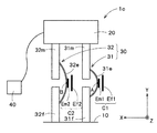
図1は、本発明の第1の実施の形態による力覚センサの基本構造1を示す概略上面図である。本図においては、左右方向にX軸が、上下方向にY軸が、奥行き方向にZ軸が、それぞれ定められているものとする。図1に示すように、基本構造1は、固定部10と、力の作用により固定部10に対してY軸方向に沿って相対移動する可動部20と、固定部10と可動部20とに接続され、可動部20が固定部10に対して相対移動することにより弾性変形を生じる変形体30と、を備えている。
<1-1. Basic structure>
FIG. 1 is a schematic top view showing a basic structure 1 of a force sensor according to a first embodiment of the present invention. In this figure, it is assumed that the X-axis is defined in the left-right direction, the Y-axis is defined in the up-down direction, and the Z-axis is defined in the depth direction. As shown in FIG. 1, the basic structure 1 includes a fixed portion 10, a movable portion 20 that moves relative to the fixed portion 10 along the Y-axis direction by the action of force, and a fixed portion 10 and a movable portion 20. And a deformable body 30 that is elastically deformed when the movable portion 20 is moved relative to the fixed portion 10.

本実施の形態による基本構造1は、Y軸方向の力の検出が可能な力覚センサに利用されるものである。図1に示すように、固定部10と可動部20とは、Y軸方向に所定の間隔を空けて配置されている。可動部20は、力を受ける受力体として機能するようになっている。   The basic structure 1 according to the present embodiment is used for a force sensor capable of detecting a force in the Y-axis direction. As shown in FIG. 1, the fixed portion 10 and the movable portion 20 are arranged at a predetermined interval in the Y-axis direction. The movable part 20 functions as a power receiving body that receives a force.

固定部10と可動部20とに接続された変形体30は、X軸方向に並列に配置された第1変形体31及び第2変形体32を有している。第1変形体31は、固定部10に接続された第1固定部側接続部31fと、可動部20に接続されY軸方向において第1固定部側接続部31fから離間して配置された第1可動部側接続部31mと、第1固定部側接続部31f及び第1可動部側接続部31mを接続する弾性変形可能な円弧状の第1弾性体31eと、を有している。第2変形体32は、固定部10に接続された第2固定部側接続部32fと、可動部20に接続されY軸方向において第2固定部側接続部32fから離間して配置された第2可動部側接続部32mと、第2固定部側接続部32f及び第2可動部側接続部32mを接続する弾性変形可能な円弧状の第2弾性体32eと、を有している。本実施の形態では、図1に示すように、第1弾性体31e及び第2弾性体32eは、共にX軸負方向(図1における右方向)に凸となるように配置されている。   The deformable body 30 connected to the fixed portion 10 and the movable portion 20 includes a first deformable body 31 and a second deformable body 32 that are arranged in parallel in the X-axis direction. The first deformable body 31 includes a first fixed portion side connection portion 31f connected to the fixed portion 10 and a first fixed portion side connection portion 31f that is connected to the movable portion 20 and spaced apart from the first fixed portion side connection portion 31f in the Y-axis direction. The first movable portion side connection portion 31m, and an elastically deformable arc-shaped first elastic body 31e that connects the first fixed portion side connection portion 31f and the first movable portion side connection portion 31m are provided. The second deformable body 32 includes a second fixed portion side connection portion 32f connected to the fixed portion 10 and a second fixed portion side connection portion 32f that is connected to the movable portion 20 and spaced apart from the second fixed portion side connection portion 32f in the Y-axis direction. 2 has a movable part side connection part 32m, and an elastically deformable arc-shaped second elastic body 32e that connects the second fixed part side connection part 32f and the second movable part side connection part 32m. In the present embodiment, as shown in FIG. 1, both the first elastic body 31e and the second elastic body 32e are arranged so as to protrude in the negative X-axis direction (the right direction in FIG. 1).

第1弾性体31e及び第2弾性体32eには、最もX軸負方向側(図1における右側)に位置する部位、すなわち、第1弾性体31e及び第2弾性体32eのX軸負側の部位のうちZ軸方向から見てY軸と平行な接線を与える部位に、それぞれ第1検出部位A及び第2検出部位Bが規定されている。図1に示す基本構造1が力覚センサとして使用される際には、これら第1検出部位A及び第2検出部位Bに生じる応力ないしX軸方向の変位に基づいて、可動部20に作用した力が計測されるようになっている。図1に示すように、第1弾性体31e及び第2弾性体32eは、曲率半径が互いに異なっている。具体的には、第1弾性体31eの曲率半径よりも第2弾性体32eの曲率半径の方が大きい。その一方で、図示されていないが、第1弾性体31e及び第2弾性体32eは、XZ平面で切断した断面形状が同一となっている。このことにより、第2弾性体32eのバネ定数の方が第1弾性体31eのバネ定数よりも小さくなっている。ここで、第1弾性体31e及び第2弾性体32eのバネ定数とは、可動部20に作用したY軸方向の力の大きさを検出部位A、Bに生じたX軸方向の変位の大きさで除した値を、意味している。   The first elastic body 31e and the second elastic body 32e are located closest to the X axis negative direction side (right side in FIG. 1), that is, on the X axis negative side of the first elastic body 31e and the second elastic body 32e. The first detection part A and the second detection part B are respectively defined in parts that give a tangent line parallel to the Y axis when viewed from the Z-axis direction. When the basic structure 1 shown in FIG. 1 is used as a force sensor, it acts on the movable portion 20 based on the stress generated in the first detection site A and the second detection site B or the displacement in the X-axis direction. Force is to be measured. As shown in FIG. 1, the first elastic body 31e and the second elastic body 32e have different radii of curvature. Specifically, the curvature radius of the second elastic body 32e is larger than the curvature radius of the first elastic body 31e. On the other hand, although not shown, the first elastic body 31e and the second elastic body 32e have the same cross-sectional shape cut along the XZ plane. Thus, the spring constant of the second elastic body 32e is smaller than the spring constant of the first elastic body 31e. Here, the spring constants of the first elastic body 31e and the second elastic body 32e refer to the magnitude of the force in the Y-axis direction that has acted on the movable portion 20 and the magnitude of the displacement in the X-axis direction that occurs in the detection portions A and B. It means the value divided by.

図2は、図1の基本構造1の可動部20がZ軸負方向に100μmだけ変位したときに各検出部位A、Bに生じる、X軸方向の変位とY軸方向の応力とを示す図表である。   FIG. 2 is a chart showing the displacement in the X-axis direction and the stress in the Y-axis direction that occur at each detection site A and B when the movable part 20 of the basic structure 1 in FIG. 1 is displaced by 100 μm in the negative Z-axis direction. It is.

図2に示すように、力の作用によって固定部10に対して可動部20がY軸負方向(図1における下方)に変位(相対移動)した場合に、各検出部位A、Bに生じる、X軸方向の変位とY軸方向の応力とが、それぞれ異なっている。具体的には、固定部10に対して可動部20がY軸負方向に100μmだけ相対移動した場合、X軸方向に生じる変位の大きさは、第1検出部位Aよりも第2検出部位Bの方が大きく、応力は、第2検出部Bよりも第1検出部位Aの方が大きい。このことから、図1に示す基本構造1は、変位について見ると第1検出部位Aよりも第2検出部位Bの方が高感度であり、応力について見ると第2検出部位Bよりも第1検出部位Aの方が高感度である、という特性を有している。   As shown in FIG. 2, when the movable part 20 is displaced (relatively moved) in the negative Y-axis direction (downward in FIG. 1) with respect to the fixed part 10 by the action of force, it occurs at each detection site A, B. The displacement in the X-axis direction is different from the stress in the Y-axis direction. Specifically, when the movable unit 20 moves relative to the fixed unit 10 by 100 μm in the negative Y-axis direction, the magnitude of the displacement that occurs in the X-axis direction is greater than the first detection site A than the second detection site B. Is larger, and the stress is larger in the first detection region A than in the second detection unit B. From this, the basic structure 1 shown in FIG. 1 is more sensitive to the second detection site B than the first detection site A when viewed in terms of displacement, and is more sensitive than the second detection site B when viewed from the stress. The detection site A has a characteristic that it has higher sensitivity.

< 1−2. 静電容量タイプの力覚センサ >
次に、以上のような基本構造1を用いた静電容量タイプの力覚センサ1cについて説明する。
<1-2. Capacitance type force sensor>
Next, a capacitance type force sensor 1c using the basic structure 1 as described above will be described.

図3は、図1の基本構造1による静電容量タイプの力覚センサ1cを示す概略上面図である。図3に示すように、力覚センサ1cは、第1検出部位Aに配置された第1変位電極Em1と、第1変位電極Em1に対向して配置され、固定部10に対して相対移動しない第1固定電極Ef1と、第2検出部位Bに配置された第2変位電極Em2と、第2変位電極Em2に対向して配置され、固定部10に対して相対移動しない第2固定電極Ef2と、を有している。図1に示すように、第1変位電極Em1及び第1固定電極Ef1は、第1容量素子C1を構成し、第2変位電極Em2及び第2固定電極Ef2は、第2容量素子C2を構成している。本実施の形態では、第1変位電極Em1及び第2変位電極Em2は、同一の面積を有している。更に、第1固定電極Ef1及び第2固定電極Ef2は、同一の面積を有している。また、第1変位電極Em1及び第1固定電極Ef1の実効対向面積及び電極間の距離は、第2変位電極Em2及び第2固定電極Ef2の実効対向面積及び電極間の距離と等しい。各電極Em1、Ef1、Em2、Ef2は、いずれも、YZ平面と平行であるように配置されている。   FIG. 3 is a schematic top view showing a capacitance type force sensor 1c according to the basic structure 1 of FIG. As shown in FIG. 3, the force sensor 1 c is disposed so as to face the first displacement electrode Em <b> 1 disposed at the first detection site A and the first displacement electrode Em <b> 1, and does not move relative to the fixed portion 10. A first fixed electrode Ef1, a second displacement electrode Em2 disposed at the second detection site B, a second fixed electrode Ef2 disposed opposite to the second displacement electrode Em2, and not moving relative to the fixed portion 10. ,have. As shown in FIG. 1, the first displacement electrode Em1 and the first fixed electrode Ef1 constitute a first capacitive element C1, and the second displacement electrode Em2 and the second fixed electrode Ef2 constitute a second capacitive element C2. ing. In the present embodiment, the first displacement electrode Em1 and the second displacement electrode Em2 have the same area. Furthermore, the first fixed electrode Ef1 and the second fixed electrode Ef2 have the same area. The effective opposing area of the first displacement electrode Em1 and the first fixed electrode Ef1 and the distance between the electrodes are equal to the effective opposing area of the second displacement electrode Em2 and the second fixed electrode Ef2 and the distance between the electrodes. All the electrodes Em1, Ef1, Em2, and Ef2 are arranged so as to be parallel to the YZ plane.

更に、図3に示すように、力覚センサ1cは、第1変形体31及び第2変形体32に生じる弾性変形に基づいて、可動部20に作用したY軸方向の力を示す電気信号を出力する検出回路40を有している。この検出回路40は、各容量素子C1、C2の静電容量値の変動量に基づいて、可動部20に作用した力を示す電気信号を出力するようになっている。なお、各容量素子C1、C2と検出回路40とを電気的に接続する配線は、図示が省略されている。   Further, as shown in FIG. 3, the force sensor 1 c generates an electric signal indicating a force in the Y-axis direction that has acted on the movable portion 20 based on the elastic deformation generated in the first deformable body 31 and the second deformable body 32. A detection circuit 40 for outputting is provided. The detection circuit 40 is configured to output an electric signal indicating the force acting on the movable portion 20 based on the variation amount of the capacitance values of the capacitive elements C1 and C2. Note that wirings that electrically connect the capacitive elements C1 and C2 and the detection circuit 40 are not shown.

次に力覚センサ1cの作用について説明する。   Next, the operation of the force sensor 1c will be described.

ここでは、Y軸負方向(図3における下方向)の力が可動部20に作用した場合を例に説明を行う。Y軸負方向の力が可動部20に作用すると、当該可動部20は、固定部10に対してY軸負方向に相対移動する。これにより、円弧状の第1弾性体31e及び第2弾性体32eは、圧縮力の作用によって、弾性変形する。この弾性変形は、第1弾性体31e及び第2弾性体32eの曲率半径が共に減少するような変形である。これにより、第1検出部位A及び第2検出部位Bが共にX軸負方向に変位する。このため、第1容量素子C1及び第2容量素子C2は、極板間距離が減少することにより、静電容量値が共に増大する。本実施の形態では、前述したように、第2弾性体32eのバネ定数の方が第1弾性体31eのバネ定数よりも小さいため、第2検出部位BのX軸負方向への変位の方が第1検出部位AのX軸負方向への変位よりも大きい。このため、第2容量素子C2は、第1容量素子C1よりも静電容量値が大きく変動する。すなわち、第2容量素子C2は、第1容量素子C1よりも高感度である。   Here, a case where a force in the negative Y-axis direction (downward in FIG. 3) acts on the movable portion 20 will be described as an example. When a force in the negative Y-axis direction acts on the movable part 20, the movable part 20 moves relative to the fixed part 10 in the negative Y-axis direction. Thereby, the arc-shaped first elastic body 31e and the second elastic body 32e are elastically deformed by the action of the compressive force. This elastic deformation is a deformation in which the radii of curvature of the first elastic body 31e and the second elastic body 32e are both reduced. Thereby, both the 1st detection part A and the 2nd detection part B are displaced to the X-axis negative direction. For this reason, both the capacitance values of the first capacitive element C1 and the second capacitive element C2 increase as the distance between the electrode plates decreases. In the present embodiment, as described above, since the spring constant of the second elastic body 32e is smaller than the spring constant of the first elastic body 31e, the displacement of the second detection site B in the negative direction of the X-axis Is larger than the displacement of the first detection site A in the negative X-axis direction. For this reason, the capacitance value of the second capacitive element C2 varies more greatly than that of the first capacitive element C1. That is, the second capacitive element C2 is more sensitive than the first capacitive element C1.

そして、検出回路40は、第1容量素子C1及び第2容量素子C2の一方の静電容量値の変動量に基づいて、可動部20に作用した力を計測する。静電容量タイプの力覚センサ1cにおいては、相対的に高感度である第2容量素子C2の静電容量値の変動量に基づいて作用した力を計測することにより、S/Nに優れた計測が可能となる。もちろん、第1容量素子C1の静電容量値の変動量に基づいて、可動部20に作用した力を計測することも可能であるし、例えば、第1容量素子C1の静電容量値の変動量に基づいて計測された力と、第2容量素子C2の静電容量値の変動量に基づいて計測された力と、の平均値を、作用した力として扱うことも可能である。   And the detection circuit 40 measures the force which acted on the movable part 20 based on the variation | change_quantity of one electrostatic capacitance value of the 1st capacitive element C1 and the 2nd capacitive element C2. The electrostatic force type force sensor 1c is excellent in S / N by measuring the acting force based on the fluctuation amount of the capacitance value of the second capacitive element C2 having relatively high sensitivity. Measurement is possible. Of course, it is also possible to measure the force acting on the movable portion 20 based on the variation amount of the capacitance value of the first capacitance element C1, and for example, the variation of the capacitance value of the first capacitance element C1. It is also possible to treat the average value of the force measured based on the amount and the force measured based on the variation amount of the capacitance value of the second capacitive element C2 as the applied force.

なお、以上の説明においては、Y軸負方向の力が可動部20に作用した場合を例に説明を行ったが、これとは逆にY軸正方向(図3における上方向)の力が可動部20に作用しても当該力の計測が可能である。この場合、第1弾性体31e及び第2弾性体32eは、それらの曲率半径が共に増大するように、弾性変形する。これにより、第1検出部位A及び第2検出部位Bは、共にX軸正方向(図3における左方向)に変位し、第1容量素子C1及び第2容量素子C2の静電容量値は、共に減少する。なお、この場合も、第2容量素子C2は、第1容量素子C1よりも静電容量値が大きく変動する。   In the above description, the case where a force in the negative Y-axis direction acts on the movable part 20 has been described as an example. On the contrary, the force in the positive Y-axis direction (upward in FIG. 3) is applied. Even if it acts on the movable part 20, the force can be measured. In this case, the first elastic body 31e and the second elastic body 32e are elastically deformed so that their radii of curvature both increase. As a result, both the first detection site A and the second detection site B are displaced in the positive X-axis direction (left direction in FIG. 3), and the capacitance values of the first capacitive element C1 and the second capacitive element C2 are Both decrease. In this case as well, the capacitance value of the second capacitive element C2 varies more greatly than the first capacitive element C1.

< 1−3. 歪ゲージタイプの力覚センサ >
あるいは、以上のような基本構造1は、歪ゲージタイプの力覚センサ1sに用いることもできる。
<1-3. Strain gauge type force sensor>
Alternatively, the basic structure 1 as described above can also be used for a strain gauge type force sensor 1s.

図4は、図1の基本構造1による歪ゲージタイプの力覚センサ1sを示す概略上面図である。図4に示すように、力覚センサ1sは、第1検出部位Aに配置された第1歪ゲージR1と、第2検出部位Bに配置された第2歪ゲージR2と、を有している。第1歪ゲージR1と第2歪ゲージR2とは、同一の特性を有している。その他の構成は、容量素子を有していない点を除き図3に示す力覚センサ1cと同様であるため、その詳細な説明は省略する。   FIG. 4 is a schematic top view showing a strain gauge type force sensor 1s according to the basic structure 1 of FIG. As shown in FIG. 4, the force sensor 1 s includes a first strain gauge R1 disposed at the first detection site A and a second strain gauge R2 disposed at the second detection site B. . The first strain gauge R1 and the second strain gauge R2 have the same characteristics. Since the other configuration is the same as that of the force sensor 1c shown in FIG. 3 except that the capacitive element is not included, detailed description thereof is omitted.

なお、歪ゲージR1、R2としては、例えば金属箔歪ゲージや半導体歪ゲージが採用され得る。金属箔歪ゲージは、圧縮応力が作用すると抵抗値が減少し、逆に引張応力が作用すると抵抗値が増大するという性質を有している。また、半導体歪ゲージは、ピエゾ抵抗効果を利用した歪ゲージであり、この半導体歪ゲージに対して引張応力が作用すると、p型の半導体歪ゲージにおいては抵抗値が増大し、n型の半導体歪ゲージにおいては抵抗値が減少するという特性がある。一方、この半導体歪ゲージに対して圧縮応力が作用すると、p型の半導体歪ゲージにおいては抵抗値が減少し、n型の半導体歪ゲージにおいては抵抗値が増大する。ここでは、第1歪ゲージR1及び第2歪ゲージR2として、金属箔歪ゲージが採用されているものとする。   As the strain gauges R1 and R2, for example, a metal foil strain gauge or a semiconductor strain gauge can be adopted. Metal foil strain gauges have the property that the resistance value decreases when compressive stress acts, and conversely the resistance value increases when tensile stress acts. The semiconductor strain gauge is a strain gauge using the piezoresistive effect. When a tensile stress acts on the semiconductor strain gauge, the resistance value increases in the p-type semiconductor strain gauge, and the n-type semiconductor strain gauge. The gauge has a characteristic that the resistance value decreases. On the other hand, when compressive stress acts on the semiconductor strain gauge, the resistance value decreases in the p-type semiconductor strain gauge, and the resistance value increases in the n-type semiconductor strain gauge. Here, it is assumed that metal foil strain gauges are employed as the first strain gauge R1 and the second strain gauge R2.

次に力覚センサ1sの作用について説明する。   Next, the operation of the force sensor 1s will be described.

Y軸負方向の力が可動部20に作用すると、当該可動部20が固定部10に対してY軸負方向に相対移動し、前述の通り、第1弾性体31e及び第2弾性体32eは、その曲率半径が共に減少するように弾性変形する。これにより、円弧状の第1弾性体31e及び第2弾性体32eのX軸負側の表面には、各検出部位A、Bを含む領域に引張応力が生じる。前述したように、第1弾性体31eのバネ定数が第2弾性体32eのバネ定数よりも大きいため、第1検出部位Aに生じる引張応力は、第2検出部位Bに生じる引張応力よりも大きい。このことは、図2を参照して前述したとおりである。このため、第1歪ゲージR1の方が第2歪ゲージR2よりも電気抵抗値が大きく変動(増大)する。   When a force in the negative Y-axis direction acts on the movable part 20, the movable part 20 moves relative to the fixed part 10 in the negative Y-axis direction. As described above, the first elastic body 31e and the second elastic body 32e are , It is elastically deformed so that its radius of curvature decreases. Thereby, tensile stress is generated in a region including the detection portions A and B on the surfaces on the X axis negative side of the arc-shaped first elastic body 31e and the second elastic body 32e. As described above, since the spring constant of the first elastic body 31e is larger than the spring constant of the second elastic body 32e, the tensile stress generated in the first detection site A is larger than the tensile stress generated in the second detection site B. . This is as described above with reference to FIG. For this reason, the electric resistance value of the first strain gauge R1 fluctuates (increases) to a greater extent than the second strain gauge R2.

そして、検出回路40は、第1歪ゲージR1及び第2歪ゲージR2の一方の電気抵抗値の変動量に基づいて、作用した力を計測する。歪ゲージタイプの力覚センサ1sにおいては、相対的に高感度である第1歪ゲージR1の電気抵抗値の変動量に基づいて作用した力を計測することにより、S/Nに優れた計測が可能となる。もちろん、第2歪ゲージR2の電気抵抗値の変動量に基づいて作用した力を計測することも可能であるし、例えば、第1歪ゲージR1の電気抵抗値の変動量に基づいて計測された力と、第2歪ゲージR2の電気抵抗値の変動量に基づいて計測された力と、の平均値を、作用した力として扱うことも可能である。   And the detection circuit 40 measures the force which acted based on the variation | change_quantity of one electrical resistance value of 1st strain gauge R1 and 2nd strain gauge R2. In the strain gauge type force sensor 1s, by measuring the force acting on the basis of the fluctuation amount of the electric resistance value of the first strain gauge R1 having relatively high sensitivity, measurement with excellent S / N can be performed. It becomes possible. Of course, it is also possible to measure the force applied based on the variation amount of the electric resistance value of the second strain gauge R2, and for example, the force was measured based on the variation amount of the electric resistance value of the first strain gauge R1. It is also possible to treat the average value of the force and the force measured based on the fluctuation amount of the electric resistance value of the second strain gauge R2 as the applied force.

なお、以上の説明においては、Y軸負方向の力が可動部20に作用した場合を例に説明を行ったが、これとは逆にY軸正方向(図4における上方向)の力が可動部20に作用しても当該力の計測が可能である。この場合、前述の通り、第1弾性体31e及び第2弾性体32eは、その曲率半径が共に増大するように弾性変形する。これにより、円弧状の第1弾性体31e及び第2弾性体32eのX軸負側の表面には、各検出部位A、Bを含む領域に圧縮応力が生じ、各歪ゲージR1、R2の電気抵抗値が共に減少する。なお、この場合も、第1歪ゲージR1は、第2歪ゲージR2よりも電気抵抗値が大きく変動する。   In the above description, the case where a force in the negative Y-axis direction is applied to the movable part 20 has been described as an example. On the contrary, the force in the positive Y-axis direction (upward in FIG. 4) is applied. Even if it acts on the movable part 20, the force can be measured. In this case, as described above, the first elastic body 31e and the second elastic body 32e are elastically deformed so that their curvature radii increase together. Thereby, compressive stress is generated in the region including the detection portions A and B on the surfaces on the X axis negative side of the arc-shaped first elastic body 31e and the second elastic body 32e, and the electric power of the strain gauges R1 and R2 is generated. Both resistance values decrease. Also in this case, the electric resistance value of the first strain gauge R1 varies more greatly than that of the second strain gauge R2.

以上のような本実施の形態による力覚センサ1c、1sによれば、バネ定数が相対的に小さい第2検出部位B、すなわち弾性変形が相対的に大きい第2検出部位Bに第2容量素子C2を配置することにより、高精度且つ高感度で力の検出が可能な静電容量タイプの力覚センサ1cを提供することができる。あるいは、バネ定数が相対的に大きい第1検出部位A、すなわち弾性変形に伴って発現する応力が相対的に大きい第1検出部位Aに第1歪ゲージR1を配置することにより、高精度且つ高感度で力の検出が可能な力覚センサ1sを提供することができる。以上から、本実施の形態によれば、共通の基本構造1を有しながら静電容量タイプとして構成しても、歪ゲージタイプとして構成しても、高精度且つ高感度で作用した力の検出が可能な力覚センサ1c、1sを提供することができる。   According to the force sensors 1c and 1s according to the present embodiment as described above, the second capacitive element is added to the second detection part B having a relatively small spring constant, that is, the second detection part B having a relatively large elastic deformation. By disposing C2, it is possible to provide a capacitance type force sensor 1c capable of detecting force with high accuracy and high sensitivity. Alternatively, by disposing the first strain gauge R1 in the first detection site A having a relatively large spring constant, that is, the first detection site A in which the stress expressed with elastic deformation is relatively large, high accuracy and high A force sensor 1 s capable of detecting force with sensitivity can be provided. As described above, according to the present embodiment, the force detected with high accuracy and high sensitivity can be detected regardless of whether it is configured as a capacitance type or a strain gauge type while having the common basic structure 1. Can be provided.

< 1−4. 波形の検出部位を有する基本構造 >
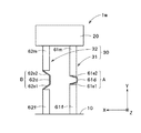
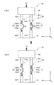
次に、図5は、図1の基本構造1の変形例を示す概略上面図である。また、図6は、図5の基本構造1wにY軸方向の力が作用している状態を示す概略上面図である。図6(a)は、基本構造1wにY軸方向に沿った圧縮力f1が作用している状態であり、図6(b)は、基本構造1wにY軸方向に沿った引張力f2が作用している状態である。
<1-4. Basic structure with waveform detection section>
Next, FIG. 5 is a schematic top view showing a modification of the basic structure 1 of FIG. FIG. 6 is a schematic top view showing a state in which a force in the Y-axis direction is applied to the basic structure 1w of FIG. FIG. 6A shows a state where a compressive force f1 along the Y-axis direction is acting on the basic structure 1w, and FIG. 6B shows a state where a tensile force f2 along the Y-axis direction is applied to the basic structure 1w. It is in a working state.

図5に示すように、本変形例では、図1の2つの円弧状の弾性体に代えて、2つの波形の弾性構造体が採用されている。ここでは、これらの波形の弾性構造体を第1検出部位A及び第2検出部位Bと呼ぶことにする。図示されるように、第1検出部位Aは、第1変位部61dと、第1変位部61dの両側に設けられ、Y軸方向に間隔を空けて配置された接続部61m、61fを介して固定部10及び可動部20にそれぞれ接続された一対の第1変形部61e1、61e2と、を有し、第2検出部位Bは、第2変位部62dと、第2変位部62dの両側に設けられ、Y軸方向に間隔を空けて配置された接続部62m、62fを介して固定部10及び可動部20にそれぞれ接続された一対の第2変形部62e1、62e2と、を有している。図5に示すように、一対の第2変形部62e1、62e2は、一対の第1変形部61e1、61e2よりもY軸方向により立ち上がった状態で構成されている。   As shown in FIG. 5, in this modification, two corrugated elastic structures are employed instead of the two arc-shaped elastic bodies of FIG. Here, the elastic structures having these waveforms are referred to as a first detection site A and a second detection site B. As shown in the drawing, the first detection site A is provided on the first displacement portion 61d and the connection portions 61m and 61f provided on both sides of the first displacement portion 61d and spaced from each other in the Y-axis direction. A pair of first deformation portions 61e1 and 61e2 connected to the fixed portion 10 and the movable portion 20, respectively, and the second detection site B is provided on both sides of the second displacement portion 62d and the second displacement portion 62d. And a pair of second deforming portions 62e1 and 62e2 respectively connected to the fixed portion 10 and the movable portion 20 via connecting portions 62m and 62f arranged at intervals in the Y-axis direction. As shown in FIG. 5, the pair of second deformable portions 62e1 and 62e2 are configured to rise in the Y-axis direction from the pair of first deformable portions 61e1 and 61e2.

ここに示す例の場合、一対の第1変形部61e1、61e2及び一対の第2変形部62e1、62e2は、可撓性を有する板状片によって構成され、第1変位部61d及び第2変位部62dは、第3の板状片によって構成されている。各板状片は、各接続部61f、61m、62f、62mと同一の材料から構成されているが、図5及び図6に示すように、相対的に肉厚の薄い板状の部材であるため、可撓性を有することになる。   In the case of the example shown here, the pair of first deforming portions 61e1 and 61e2 and the pair of second deforming portions 62e1 and 62e2 are configured by flexible plate-like pieces, and the first displacement portion 61d and the second displacement portion. 62d is comprised by the 3rd plate-shaped piece. Each plate-like piece is made of the same material as each connection portion 61f, 61m, 62f, 62m, but is a relatively thin plate-like member as shown in FIGS. Therefore, it has flexibility.

なお、ここに示す例の場合、第1変位部61d及び第2変位部62dも肉厚の薄い板状の部材であるため可撓性を有しているが、基本構造1wを静電容量タイプの力覚センサとして利用する場合には、当該第1変位部61d及び第2変位部62dは、必ずしも可撓性をもった部材である必要はない。一方、基本構造1wを歪ゲージタイプの力覚センサとして利用する場合には、第1変位部61d及び第2変位部62dが可撓性をもった部材である必要がある。図5及び図6に示す例では、第1変位部61d及び第2変位部62d(第3の板状片)は、左右両面がYZ平面に平行な面となっている。   In the case of the example shown here, the first displacement part 61d and the second displacement part 62d are also flexible because they are thin plate members, but the basic structure 1w is a capacitance type. When used as a force sensor, the first displacement portion 61d and the second displacement portion 62d do not necessarily have to be flexible members. On the other hand, when the basic structure 1w is used as a strain gauge type force sensor, the first displacement portion 61d and the second displacement portion 62d need to be flexible members. In the example shown in FIGS. 5 and 6, the first displacement portion 61d and the second displacement portion 62d (third plate-like piece) have both left and right surfaces parallel to the YZ plane.

次に、図6(a)及び図6(b)を参照して、基本構造1wの可動部20に対して、Y軸方向に沿った力が作用した時の、各検出部位A、Bの作用について説明する。図6(a)及び図6(b)において、黒塗りの太い矢印は、作用する力の方向を示しており、白抜きの太い矢印は、各変位部61d、62dの変位の方向を示している。   Next, with reference to FIG. 6A and FIG. 6B, each of the detection sites A and B when a force along the Y-axis direction acts on the movable portion 20 of the basic structure 1w. The operation will be described. In FIG. 6A and FIG. 6B, the thick black arrow indicates the direction of the acting force, and the white thick arrow indicates the direction of displacement of each of the displacement portions 61d and 62d. Yes.

図6(a)に示すように、基本構造1wの可動部20に対して、Y軸方向に沿った圧縮力f1が作用すると、各検出部位A、Bには、Y軸方向に沿った圧縮力が作用する。このため、一対の第1変形部61e1、61e2及び一対の第2変形部62e1、62e2の姿勢は、より水平に寝た状態に変化する。その結果、各変位部61d、62dは、図に白抜きの矢印で示す通り、X軸負方向(図6(a)における右方向)に変位する。一方、図6(b)に示すように、基本構造1wの可動部20に対して、Y軸正方向の引張力f2が作用すると、各検出部位A、Bには、Y軸方向に沿った引張力が作用する。このため、一対の第1変形部61e1、61e2及び一対の第2変形部62e1、62e2の姿勢は、より垂直に立った状態に変化する。その結果、各変位部61d、62dは、図に白抜きの矢印で示す通り、X軸正方向(図6(b)における左方向)に変位する。   As shown in FIG. 6A, when the compressive force f1 along the Y-axis direction acts on the movable portion 20 of the basic structure 1w, the detection sites A and B are compressed along the Y-axis direction. Force acts. For this reason, the postures of the pair of first deforming portions 61e1 and 61e2 and the pair of second deforming portions 62e1 and 62e2 change to a state of lying more horizontally. As a result, each of the displacement portions 61d and 62d is displaced in the negative X-axis direction (the right direction in FIG. 6A) as indicated by the white arrow in the figure. On the other hand, as shown in FIG. 6B, when a tensile force f2 in the positive Y-axis direction acts on the movable portion 20 of the basic structure 1w, each detection site A, B is along the Y-axis direction. A tensile force acts. For this reason, the postures of the pair of first deforming portions 61e1 and 61e2 and the pair of second deforming portions 62e1 and 62e2 change to a more vertically standing state. As a result, each of the displacement portions 61d and 62d is displaced in the positive X-axis direction (left direction in FIG. 6B) as indicated by a white arrow in the figure.

前述したように、一対の第1変形部61e1、61e2は、初期状態(図5参照)において、一対の第2変形部62e1、62e2よりもY軸方向により立ち上がった状態で構成されている。このため、図6(a)及び図6(b)に示すように、力の作用によって生じる変位は、第1変位部61dよりも第2変位部62dの方が、相対的に大きい。換言すれば、第1検出部位Aのバネ定数よりも第2検出部位Bのバネ定数の方が相対的に小さい。ここで、第1検出部位A及び第2検出部位Bのバネ定数とは、可動部20に作用した力を変位部61d、62dに生じたX軸方向の変位で除した値を意味している。   As described above, the pair of first deformable portions 61e1 and 61e2 are configured to rise in the Y-axis direction from the pair of second deformable portions 62e1 and 62e2 in the initial state (see FIG. 5). For this reason, as shown in FIGS. 6A and 6B, the displacement caused by the action of the force is relatively larger in the second displacement portion 62d than in the first displacement portion 61d. In other words, the spring constant of the second detection site B is relatively smaller than the spring constant of the first detection site A. Here, the spring constants of the first detection site A and the second detection site B mean values obtained by dividing the force acting on the movable portion 20 by the displacement in the X-axis direction generated in the displacement portions 61d and 62d. .

基本構造1wを用いた力覚センサにおいては、このような変位を利用して、作用した力の向きおよび大きさが検出されるようになっている。すなわち、作用した力の向きは、各変位部61d、62dの変位方向によって検出され、作用した力の大きさは、その変位の大きさによって検出されるようになっている。   In the force sensor using the basic structure 1w, the direction and magnitude of the applied force are detected using such displacement. That is, the direction of the applied force is detected by the displacement direction of each of the displacement parts 61d and 62d, and the magnitude of the applied force is detected by the magnitude of the displacement.

以上のような本実施の形態による力覚センサによれば、バネ定数が相対的に小さい第2検出部位B、すなわち相対的に大きい弾性変形が生じる第2検出部位Bに容量素子C2を配置することにより、高精度且つ高感度で力の検出が可能な力覚センサ1cを提供することができる。   According to the force sensor according to the present embodiment as described above, the capacitive element C2 is arranged in the second detection portion B having a relatively small spring constant, that is, the second detection portion B in which relatively large elastic deformation occurs. Thereby, the force sensor 1c which can detect force with high accuracy and high sensitivity can be provided.

あるいは、以上のような基本構造1wを歪ゲージ式の力覚センサに用いることも可能である。歪ゲージ式の力覚センサを構成するには、静電容量タイプの力覚センサの各変位部61d、62dに配置された容量素子に代えて、具体的には変位電極に代えて、歪ゲージR1、R2を配置すればよい。   Alternatively, the basic structure 1w as described above can be used for a strain gauge type force sensor. In order to construct a strain gauge type force sensor, in place of the capacitive elements arranged at the displacement portions 61d and 62d of the capacitance type force sensor, more specifically, instead of the displacement electrodes, the strain gauge R1 and R2 may be arranged.

図7は、このようにして構成された歪ゲージタイプの力覚センサの第1検出部位Aの部分的な概略上面図を示している。図7(a)は、第1検出部位Aの初期状態を示す概略図であり、図7(b)は、基本構造1wに圧縮力が作用した時の第1検出部位Aを示す概略図であり、図7(c)は、基本構造1wに引張力が作用した時の第1検出部位Aを示す概略図である。各図において、黒塗りの太い矢印は、作用する力の方向を示しており、細い矢印は、各変位部61d、62dのX軸負側の表面に生じる応力(「→ ←」は圧縮応力、「← →」は引張応力)を示している。   FIG. 7 is a partial schematic top view of the first detection portion A of the strain gauge type force sensor configured as described above. FIG. 7A is a schematic diagram illustrating an initial state of the first detection site A, and FIG. 7B is a schematic diagram illustrating the first detection site A when a compressive force is applied to the basic structure 1w. FIG. 7C is a schematic diagram showing the first detection site A when a tensile force is applied to the basic structure 1w. In each drawing, the thick black arrow indicates the direction of the acting force, and the thin arrow indicates the stress (“→ ←” is a compressive stress, which is generated on the surface on the negative side of the X axis of each displacement portion 61d, 62d. “← →” indicates tensile stress).

図7(a)に示すように、初期状態における第1検出部位Aの第1変位部61dは、ZY平面と平行である。そして、図7(b)に示すように、基本構造1wに圧縮力が作用すると、前述したように、一対の第1変形部61e1、61e2の姿勢は、より水平に寝た状態に変化する。このことによって、図7(b)に示すように、第1検出部位Aの第1変位部61dは、X軸負方向(図7(b)における右方向)に凸となるように撓み変形する。すなわち、図示されるように、第1歪ゲージR1が配置されている第1変位部61dのX軸負側の面には、Y軸方向に沿って、引張応力が生じる。一方、図7(c)に示すように、基本構造1wに引張力が作用すると、前述したように、一対の第1変形部61e1、61e2の姿勢は、より垂直に立った状態に変化する。このことによって、図7(c)に示すように、第1検出部位Aの第1変位部61dは、X軸正方向(図7(c)における左方向)に凸となるように撓み変形する。すなわち、図示されるように、第1歪ゲージR1が配置されている第1変位部61dのX軸負側の面には、Y軸方向に沿って、圧縮応力が生じる。結局、第1検出部位A1に作用する力の向き(圧縮か引張か)と第1変位部61dのX軸負側の面に生じる応力の向き(圧縮か引張か)とは、互いに逆になる。なお、図7(b)及び図7(c)の撓み変形の態様から理解されるように、第1変位部61dのX軸正側の面に生じる応力の向き(圧縮か引張か)は、第1検出部位A1に作用する力の向き(圧縮か引張か)と同じになる。   As shown in FIG. 7A, the first displacement portion 61d of the first detection site A in the initial state is parallel to the ZY plane. And as shown in FIG.7 (b), when compressive force acts on the basic structure 1w, as above-mentioned, the attitude | position of a pair of 1st deformation | transformation part 61e1, 61e2 will change to the state which lay down more horizontally. As a result, as shown in FIG. 7B, the first displacement portion 61d of the first detection site A is bent and deformed so as to be convex in the X-axis negative direction (right direction in FIG. 7B). . That is, as shown in the drawing, tensile stress is generated along the Y-axis direction on the X-axis negative side surface of the first displacement portion 61d on which the first strain gauge R1 is disposed. On the other hand, as shown in FIG. 7C, when a tensile force acts on the basic structure 1w, as described above, the postures of the pair of first deformable portions 61e1 and 61e2 change to a more vertical state. As a result, as shown in FIG. 7C, the first displacement portion 61d of the first detection site A is bent and deformed so as to be convex in the X-axis positive direction (left direction in FIG. 7C). . That is, as shown in the drawing, compressive stress is generated along the Y-axis direction on the surface on the X-axis negative side of the first displacement portion 61d where the first strain gauge R1 is disposed. Eventually, the direction of the force acting on the first detection site A1 (compression or tension) and the direction of the stress (compression or tension) generated on the X-axis negative side surface of the first displacement portion 61d are opposite to each other. . As can be understood from the bending deformation modes of FIGS. 7B and 7C, the direction of the stress (compression or tension) generated on the X-axis positive side surface of the first displacement portion 61d is: This is the same as the direction of force (compression or tension) acting on the first detection site A1.

図7には、第2検出部位Bが示されていないが、当該第2検出部位Bにおいても、第2変位部62dに同様の撓み変形が生じる。但し、前述したように、第1検出部位Aよりも第2検出部位の方が相対的に小さいバネ定数を有することから、第1変位部61dに生じる応力の方が、第2変位部62dに生じる応力よりも、大きい。このことから、第1変位部61dに配置された第1歪ゲージを用いて作用した力Fyを検出することにより、高精度且つ高感度で力の検出が可能な力覚センサ1sを提供することができる。   Although the second detection site B is not shown in FIG. 7, the same bending deformation occurs in the second displacement portion 62d also in the second detection site B. However, as described above, since the second detection portion has a relatively smaller spring constant than the first detection portion A, the stress generated in the first displacement portion 61d is applied to the second displacement portion 62d. Greater than the resulting stress. From this, it is possible to provide a force sensor 1 s capable of detecting force with high accuracy and high sensitivity by detecting the force Fy applied using the first strain gauge arranged in the first displacement portion 61 d. Can do.

以上から、本実施の形態によれば、静電容量タイプとして構成しても、歪ゲージタイプとして構成しても、高精度且つ高感度で力の検出が可能な力覚センサ1c、1sを提供することができる。   As described above, according to the present embodiment, there are provided force sensors 1c and 1s capable of detecting force with high accuracy and high sensitivity regardless of whether they are configured as a capacitance type or a strain gauge type. can do.

また、第1検出部位A及び第2検出部位Bは、可動部20と固定部10との間に並列に配置されているため、第1検出部位A及び第2検出部位Bに大きな変形ないし変位を生じさせることができ、作用した力をより高精度且つ高感度で検出することができる。   Further, since the first detection part A and the second detection part B are arranged in parallel between the movable part 20 and the fixed part 10, the first detection part A and the second detection part B are greatly deformed or displaced. The applied force can be detected with higher accuracy and higher sensitivity.

更に、図1に示す基本構造1の第1検出部位Aは、所定の半径を有する円弧の一部に沿った形状を有し、第2検出部位Bは、前記所定の半径とは異なる半径を有する円弧の一部に沿った形状を有していている。このため、第1検出部位A及び第2検出部位Bに、作用した力と直交する方向に変位を生じさせることができるため、力の計測が容易である。こことは、図5に示す基本構造1wにおいても、同様である。   Further, the first detection site A of the basic structure 1 shown in FIG. 1 has a shape along a part of an arc having a predetermined radius, and the second detection site B has a radius different from the predetermined radius. It has a shape along a part of the arc. For this reason, since it is possible to cause the first detection site A and the second detection site B to be displaced in a direction orthogonal to the applied force, the force can be easily measured. The same applies to the basic structure 1w shown in FIG.

<<< §2. 本発明の第2の実施の形態による力覚センサ >>>
次に、本発明の第2の実施の形態による力覚センサについて詳細に説明する。
<<< §2. Force sensor according to the second embodiment of the present invention >>
Next, a force sensor according to a second embodiment of the present invention will be described in detail.

< 2−1. 基本構造 >
図8は、本発明の第2の実施の形態による力覚センサの基本構造101を示す概略上面図であり、図9は、受力体としての可動部120にZ軸周りのモーメントが作用した時の図8の基本構造101を示す概略上面図であり、図10は、図8の基本構造101の第2象限部分を示す概略上面図である。
<2-1. Basic structure>
FIG. 8 is a schematic top view showing the basic structure 101 of the force sensor according to the second embodiment of the present invention, and FIG. 9 shows a moment around the Z-axis acting on the movable part 120 as a force receiving body. FIG. 10 is a schematic top view showing the basic structure 101 of FIG. 8 at the time, and FIG. 10 is a schematic top view showing a second quadrant of the basic structure 101 of FIG.

本実施の形態による力覚センサは、XYZ三次元座標系における各軸方向の力及び各軸まわりのモーメントの少なくとも1つを検出するためのものである。図8乃至図10に示すように、基本構造101は、XYZ三次元座標系に対して固定された固定部110と、力ないしモーメントの作用により固定部110に対して相対移動する可動部120と、固定部110と可動部120とに接続され、可動部120が固定部110に対して相対移動することにより弾性変形を生じる変形体140と、を有している。   The force sensor according to the present embodiment is for detecting at least one of a force in each axial direction and a moment around each axis in an XYZ three-dimensional coordinate system. As shown in FIGS. 8 to 10, the basic structure 101 includes a fixed part 110 fixed with respect to the XYZ three-dimensional coordinate system, and a movable part 120 that moves relative to the fixed part 110 by the action of a force or a moment. And a deformable body 140 that is connected to the fixed portion 110 and the movable portion 120 and generates elastic deformation when the movable portion 120 moves relative to the fixed portion 110.

図8乃至図10に示すように、固定部110は、XY平面上に固定され、Z軸正方向から見て、原点を中心とする円盤の形状を有している。可動部120は、Z軸正方向から見て、XY平面上に固定部110と同心に配置された円環の形状を有している。なお、固定部110も円環の形状を有していても良い。   As shown in FIGS. 8 to 10, the fixing portion 110 is fixed on the XY plane and has a disk shape centered on the origin when viewed from the positive direction of the Z axis. The movable part 120 has an annular shape arranged concentrically with the fixed part 110 on the XY plane when viewed from the positive direction of the Z axis. Note that the fixing portion 110 may also have an annular shape.

また、図8乃至図10に示すように、変形体140は、弾性体から構成された円環の形状の第1変形体141と、当該第1変形体141を取り囲むように配置され、弾性体から構成された円環の形状の第2変形体142と、を有している。Z軸正方向から見て、第1変形体141は、固定部110を取り囲むように当該固定部110と同心に配置され、第2変形体142は、第1変形体141と可動部120との間にそれらと同心に配置されている。結局、固定部110、第1変形体141、第2変形体142及び可動部120は、Z軸正方向から見て、互いに同心に、且つ、径方向外側に向かってこの順序で、配置されている。   Also, as shown in FIGS. 8 to 10, the deformable body 140 is arranged so as to surround the first deformable body 141 in the shape of a ring made of an elastic body and the first deformable body 141. And a second deformable body 142 having an annular shape constituted by When viewed from the positive direction of the Z axis, the first deformable body 141 is disposed concentrically with the fixed portion 110 so as to surround the fixed portion 110, and the second deformable body 142 is formed between the first deformable body 141 and the movable portion 120. They are placed concentrically with them. After all, the fixed portion 110, the first deformable body 141, the second deformable body 142, and the movable portion 120 are arranged in this order concentrically with each other and radially outward as viewed from the positive Z-axis direction. Yes.

また、本実施の形態による基本構造101の第1変形体141及び第2変形体142は、同一の断面形状を有している。このため、各変形体141、142の直径の相違から、第1変形体141の各検出部位A1〜A4のバネ定数は、第2変形体の各検出部位B1〜B4のバネ定数より大きい。ここで、各検出部位A1〜A4、B1〜B4のバネ定数とは、可動部20に作用した力を各検出部位1〜A4、B1〜B4に生じたV軸方向及びW軸方向の変位で除した値を意味している。   Moreover, the 1st deformation body 141 and the 2nd deformation body 142 of the basic structure 101 by this Embodiment have the same cross-sectional shape. For this reason, due to the difference in diameter between the deformable bodies 141 and 142, the spring constants of the detection portions A1 to A4 of the first deformable body 141 are larger than the spring constants of the detection portions B1 to B4 of the second deformable body. Here, the spring constants of the detection parts A1 to A4 and B1 to B4 are the displacements in the V-axis direction and the W-axis direction generated by the forces acting on the movable part 20 in the detection parts 1 to A4 and B1 to B4. It means the value divided.

図8乃至図10に示すように、固定部110と第1変形体141とは、互いの隙間において正のY軸上に配置された連結体133と負のY軸上に配置された連結体137とによって、互いに連結されている。更に、第1変形体141と第2変形体142とは、互いの隙間において正のY軸上に配置された連結体134と負のY軸上に配置された連結体138とによって、互いに連結されている。これらのことにより、第1変形体141及び第2変形体142は、Y軸上に位置する各2つの部位が固定部110に対して相対移動しないようになっている。   As shown in FIGS. 8 to 10, the fixing portion 110 and the first deformable body 141 are a connecting body 133 disposed on the positive Y axis and a connecting body disposed on the negative Y axis in a gap between each other. 137 to each other. Further, the first deformable body 141 and the second deformable body 142 are connected to each other by the connecting body 134 disposed on the positive Y axis and the connecting body 138 disposed on the negative Y axis in the gap between each other. Has been. As a result, the first deformable body 141 and the second deformable body 142 are configured such that the two portions located on the Y axis do not move relative to the fixed portion 110.

更に、図8乃至図10に示すように、第1変形体141と第2変形体142とは、互いの隙間において正のX軸上に配置された連結体131と負のX軸上に配置された連結体135とによって、互いに連結されている。更に、可動部120と第2変形体142とは、互いの隙間において正のX軸上に配置された連結体132と負のX軸上に配置された連結体136とによって、互いに連結されている。これらのことにより、第1変形体141及び第2変形体142は、X軸上に位置する各2つの部位が可動部120と一体的に固定部110に対して相対移動するようになっている。   Further, as shown in FIGS. 8 to 10, the first deformable body 141 and the second deformable body 142 are disposed on the negative X axis and the connecting body 131 disposed on the positive X axis in the gap between each other. The connected body 135 is connected to each other. Furthermore, the movable part 120 and the second deformable body 142 are coupled to each other by a coupling body 132 disposed on the positive X axis and a coupling body 136 disposed on the negative X axis in a gap between each other. Yes. As a result, the first deformable body 141 and the second deformable body 142 are configured such that the two portions located on the X axis move relative to the fixed portion 110 integrally with the movable portion 120. .

次に、このような基本構造101の可動部120にZ軸周りのモーメント−Mzが作用した時の、当該基本構造101の作用について図9を参照して説明する。図9において、黒塗りの太い矢印は、作用する力の方向を示しており、白抜きの太い矢印は、各検出部位A1〜A4、B1〜B4の変位の方向を示している。   Next, the action of the basic structure 101 when the moment -Mz around the Z-axis acts on the movable part 120 of the basic structure 101 will be described with reference to FIG. In FIG. 9, the thick black arrow indicates the direction of the acting force, and the thick thick arrow indicates the direction of displacement of each of the detection sites A1 to A4 and B1 to B4.

図9に示すように、モーメント−Mzの作用によって可動部120が固定部110に対してZ軸正方向から見て右回りに相対回転されると、第1及び第2変形体141、142のうち、連結体131、132によって連結されている正のX軸上の部位がY軸負方向(図9における下方)へ、連結体135、136によって連結されている負のX軸上の部位がY軸正方向(図9における上方)へ、それぞれ移動する。一方、第1及び第2変形体141、142のうち、連結体133、134、137、138で連結されているY軸上の部位は、移動しない。これらのことによって、各変形体141、142に次のような弾性変形が生じる。すなわち、XY平面上に、原点Oを通りX軸およびY軸に対して45°をなすV軸およびW軸を定義した場合に、各変形体141、142のうち、W軸上に位置する部位においては、径方向外方への変位が生じ、V軸上に位置する部位においては、径方向内方への変位が生じる。一方、図示されていないが、可動部120に反対方向の力が作用して当該可動部120が固定部110に対して左回りに相対回転されると、W軸上に位置する部位においては、径方向内方への変位が生じ、V軸上に位置する部位においては、径方向外方への変位が生じる。   As shown in FIG. 9, when the movable portion 120 is rotated relative to the fixed portion 110 clockwise by the action of the moment −Mz, the first and second deformable bodies 141 and 142 Among these, the portion on the positive X-axis connected by the connecting bodies 131 and 132 is the Y-axis negative direction (downward in FIG. 9), and the portion on the negative X-axis connected by the connecting bodies 135 and 136 is Each moves in the Y-axis positive direction (upward in FIG. 9). On the other hand, of the first and second deformable bodies 141 and 142, the portions on the Y axis that are connected by the connecting bodies 133, 134, 137, and 138 do not move. As a result, the following elastic deformation occurs in each of the deformable bodies 141 and 142. That is, when the V axis and the W axis that pass through the origin O and form an angle of 45 ° with respect to the X axis and the Y axis are defined on the XY plane, the part located on the W axis among the deformable bodies 141 and 142 In, a radially outward displacement occurs, and a radially inward displacement occurs in a portion located on the V-axis. On the other hand, although not shown, when a force in the opposite direction acts on the movable part 120 and the movable part 120 is rotated counterclockwise with respect to the fixed part 110, in a portion located on the W axis, A radially inward displacement occurs, and a radially outward displacement occurs at a portion located on the V axis.

これらの変位は、W軸上及びV軸上で最大となることから、正のZ軸方向から見て、各変形体141、142のうちW軸及びV軸と交わる部位の変位ないし応力に着目して作用した力ないしモーメントを計測することが効率的である。このため、ここでは、図9に示すように、第1変形体141のうちW軸及びV軸と交わる4つの部位を第1象限から順に第1−1検出部位A1、第1−2検出部位A2、第1−3検出部位A3及び第1−4検出部位A4とし、第2変形体142のうちW軸及びV軸と交わる4つの部位を第1象限から順に第2−1検出部位B1、第2−2検出部位B2、第3−3検出部位B3及び第2−4検出部位B4とする。   Since these displacements are maximum on the W-axis and the V-axis, pay attention to the displacements or stresses of the portions of the deformable bodies 141 and 142 that intersect the W-axis and the V-axis when viewed from the positive Z-axis direction. It is efficient to measure the force or moment that is applied. Therefore, here, as shown in FIG. 9, four portions intersecting the W-axis and the V-axis in the first deformable body 141 are sequentially arranged from the first quadrant to the 1-1 detection portion A1 and the 1-2 detection portion. A2, 1st-3 detection part A3 and 1-4 detection part A4, and the 4th part which intersects with the W axis and V axis among the 2nd modification 142 is the 2nd-1 detection part B1, in order from the 1st quadrant, Let it be the 2-2 detection site B2, the 3-3 detection site B3, and the 2-4 detection site B4.

ここで、本実施の形態による基本構造101と第1の実施の形態による基本構造1との関連性について、図10を参照して説明する。   Here, the relationship between the basic structure 101 according to the present embodiment and the basic structure 1 according to the first embodiment will be described with reference to FIG.

前述したように、本実施の形態による基本構造101は、各変形体141、142のうち正のY軸上に位置する部位がXYZ三次元座標系に対して固定されており、各変形体141、142のうち負のX軸上に位置する部位が可動部120と共に固定部110に対して一体的に相対移動するようになっている。このような構造は、各変形体141、142の正のY軸上に位置する部位を第1の実施の形態による基本構造1の固定部10と捉え、各変形体141、142の負のX軸上に位置する部位を第1の実施の形態による基本構造1の可動部20と捉えることによって、図10に示す構造と第1の実施の形態による基本構造1とが実質的に同じ構造であると理解される。同様のことは、第1、第3及び第4象限においても成立する。更に、各変形体141、142のバネ定数の関係は、第1の実施の形態における基本構造1において、第1変形体31の第1検出部位Aのバネ定数が第2変形体32の第2検出部位Bのバネ定数より大きい、ということとも対応している。   As described above, in the basic structure 101 according to the present embodiment, a portion of the deformable bodies 141 and 142 located on the positive Y axis is fixed with respect to the XYZ three-dimensional coordinate system, and the deformable bodies 141 are arranged. , 142 are located on the negative X-axis and move relative to the fixed portion 110 together with the movable portion 120. In such a structure, a portion located on the positive Y axis of each of the deformable bodies 141 and 142 is regarded as the fixing portion 10 of the basic structure 1 according to the first embodiment, and the negative X of each of the deformable bodies 141 and 142 is taken. By grasping the part located on the axis as the movable part 20 of the basic structure 1 according to the first embodiment, the structure shown in FIG. 10 and the basic structure 1 according to the first embodiment are substantially the same structure. It is understood that there is. The same is true for the first, third and fourth quadrants. Furthermore, the relationship between the spring constants of the deformable bodies 141 and 142 is that the spring constant of the first detection portion A of the first deformable body 31 is the second constant of the second deformable body 32 in the basic structure 1 in the first embodiment. It corresponds also to being larger than the spring constant of the detection part B.

結局、図8及び図9に示す基本構造101は、第1の実施の形態による基本構造1を4つ組み合わせたものであると言える。すなわち、本実施の形態による基本構造101は、第1の実施の形態において説明したように、変位について見ると第1−1〜第1−4検出部位A1〜A4よりも第2−1〜第2−4検出部位B1〜B4の方が高感度であり、応力について見ると第2−1〜第2−4検出部位B1〜B4よりも第1−1〜第1−4検出部位A1〜A4の方が高感度である、という特性を有している。   After all, it can be said that the basic structure 101 shown in FIGS. 8 and 9 is a combination of four basic structures 1 according to the first embodiment. In other words, as described in the first embodiment, the basic structure 101 according to the present embodiment is 2-1st to 1st to 1st-4th detection sites A1 to A4 in terms of displacement. 2-4 detection site | parts B1-B4 are more sensitive, and when it sees about stress, it will be 1-1 to 1-4 detection site | parts A1-A4 rather than the 2-1st-2nd detection site | part B1-B4. It has the characteristic that is more sensitive.

< 2−2. 静電容量タイプの力覚センサ >
次に、以上のような基本構造101を用いた、静電容量タイプの力覚センサ101cについて説明する。
<2-2. Capacitance type force sensor>
Next, a capacitance type force sensor 101c using the basic structure 101 as described above will be described.

図11は、図8の基本構造101による静電容量タイプの力覚センサ101cを示す概略上図である。図11に示すように、力覚センサ101cは、第1−1〜第1−4検出部位A1〜A4の外面に配置された第1−1〜第1−4変位電極Em11〜Em14と、各変位電極Em11〜Em14に対向して配置され、固定部110に対して相対移動しない第1−1〜第1−4固定電極Ef11〜Ef14と、第2−1〜第2−4検出部位B1〜B4の外面に配置された第2−1〜第2−4変位電極Em21〜Em24と、各変位電極Em21〜Em24に対向して配置され、固定部110に対して相対移動しない第2−1〜第2−4固定電極Ef21〜Ef24と、を有している。   FIG. 11 is a schematic top view showing an electrostatic force type force sensor 101c according to the basic structure 101 of FIG. As shown in FIG. 11, the force sensor 101c includes first to first to fourth displacement electrodes Em11 to Em14 disposed on the outer surfaces of the first to first to first to fourth detection portions A1 to A4. The first to first to fourth fixed electrodes Ef11 to Ef14, which are arranged to face the displacement electrodes Em11 to Em14 and do not move relative to the fixed portion 110, and the first to second to fourth detection sites B1 to B1. The 2-1 to 2-4 displacement electrodes Em21 to Em24 disposed on the outer surface of B4, and the 2-1 to 2-1 that are disposed to face the displacement electrodes Em21 to Em24 and do not move relative to the fixed portion 110. Second to fourth fixed electrodes Ef21 to Ef24.

図11に示すように、第1−1変位電極Em11及び第1−1固定電極Ef11は、第1−1容量素子C11を構成し、第1−2変位電極Em12及び第1−2固定電極Ef12は、第1−2容量素子C12を構成し、第1−3変位電極Em13及び第1−3固定電極Ef13は、第1−3容量素子C13を構成し、第1−4変位電極Em14及び第1−4固定電極Ef14は、第1−4容量素子C14を構成している。更に、第2−1変位電極Em21及び第2−1固定電極Ef21は、第2−1容量素子C21を構成し、第2−2変位電極Em22及び第2−2固定電極Ef22は、第2−2容量素子C22を構成し、第2−3変位電極Em23及び第2−3固定電極Ef23は、第2−3容量素子C23を構成し、第2−4変位電極Em24及び第2−4固定電極Ef24は、第2−4容量素子C24を構成している。各固定電極Ef11〜Ef24は、例えばXY平面に固定され正のZ軸方向に延びる支持体(不図示)によって、可動部120に力が作用しても第1及び第2変形体141、142と干渉しない位置に、支持されている。   As shown in FIG. 11, the 1-1 displacement electrode Em11 and the 1-1 fixed electrode Ef11 constitute a 1-1 capacitive element C11, and the 1-2 displacement electrode Em12 and the 1-2 fixed electrode Ef12. Constitutes the first-second capacitance element C12, the first-third displacement electrode Em13 and the first-third fixed electrode Ef13 constitute the first-third capacitance element C13, and the first-fourth displacement electrode Em14 and the first The 1-4 fixed electrode Ef14 constitutes a 1-4 capacitive element C14. Furthermore, the 2-1 displacement electrode Em21 and the 2-1 fixed electrode Ef21 constitute a 2-1 capacitive element C21, and the 2-2 displacement electrode Em22 and the 2-2 fixed electrode Ef22 are the second 2- The second-capacitance element C22 constitutes the second-third displacement electrode Em23 and the second-third fixed electrode Ef23, and the second-third capacitance element C23 constitutes the second-fourth displacement electrode Em24 and the second-fourth fixed electrode. Ef24 constitutes the second-fourth capacitive element C24. Each of the fixed electrodes Ef11 to Ef24 is fixed to the XY plane and extends in the positive Z-axis direction, for example, even if a force acts on the movable portion 120, the first and second deformable bodies 141 and 142 It is supported at a position where it does not interfere.

本実施の形態では、第1−1〜第1−4変位電極Em11〜Em14及び第2−1〜第2−4変位電極Em21〜Em24は、全て同一の面積を有している。更に、第1−1〜第1−4固定電極Ef11〜Ef14及び第2−1〜第2−4固定電極Ef21〜Ef24は、全て同一の面積を有している。また、各容量素子C11〜C24を構成する各電極の実効対向面積及び対向する電極間の距離は、全て同一である。   In the present embodiment, the 1-1 to 1-4 displacement electrodes Em11 to Em14 and the 2-1 to 2-4 displacement electrodes Em21 to Em24 all have the same area. Furthermore, the 1-1 to 1-4 fixed electrodes Ef11 to Ef14 and the 2-1 to 2-4 fixed electrodes Ef21 to Ef24 all have the same area. Further, the effective opposing area of each electrode constituting each of the capacitive elements C11 to C24 and the distance between the opposing electrodes are all the same.

更に、図11に示すように、力覚センサ101cは、第1変形体141及び第2変形体142に生じる弾性変形に基づいて、可動部120に作用した力ないしモーメントを示す電気信号を出力する検出回路150を有している。図11に示す力覚センサ101cの検出回路150は、各容量素子C11〜C24の静電容量値の変動量に基づいて、可動部120に作用した力ないしモーメントを示す電気信号を出力するようになっている。なお、各容量素子C11〜C24と検出回路150とを電気的に接続する配線は、図示が省略されている。   Further, as shown in FIG. 11, the force sensor 101 c outputs an electrical signal indicating a force or a moment acting on the movable portion 120 based on the elastic deformation generated in the first deformable body 141 and the second deformable body 142. A detection circuit 150 is included. The detection circuit 150 of the force sensor 101c shown in FIG. 11 outputs an electrical signal indicating the force or moment acting on the movable part 120 based on the variation amount of the capacitance value of each of the capacitive elements C11 to C24. It has become. Note that wirings that electrically connect the capacitive elements C11 to C24 and the detection circuit 150 are not shown.

次に力覚センサ101cの作用について説明する。   Next, the operation of the force sensor 101c will be described.

ここでは、Z軸正方向から見て右回りの力(モーメント)が可動部120に作用した場合を例に説明を行う(図9参照)。この場合、前述したように、各変形体141、142のうち、W軸上に位置する第1−2、第2−2、第1−4、第2−4検出部位A2、B2、A4、B4においては、径方向外方への変位が生じ、V軸上に位置する第1−1、第2−1、第1−3、第2−3検出部位A1、B1、A3、B3においては、径方向内方への変位が生じる。これにより、第1−2、第2−2、第1−4、第2−4容量素子C12、C22、C14、C24は、それぞれの電極間距離が減少するため静電容量値が増大する。これに対し、第1−1、第2−1、第1−3、第2−3容量素子C11、C21、C13、C23は、それぞれの電極間距離が増大するため静電容量値が減少する。   Here, the case where a clockwise force (moment) as viewed from the positive direction of the Z-axis acts on the movable portion 120 will be described as an example (see FIG. 9). In this case, as described above, among the deformable bodies 141 and 142, the first, second, second, first, and second-4 detection sites A2, B2, A4, which are located on the W axis, In B4, a radially outward displacement occurs, and in the 1-1, 2-1, 1-3, 2-3 detection sites A1, B1, A3, B3 located on the V-axis A displacement inward in the radial direction occurs. As a result, the capacitance values of the 1-2, 2-2, 1-4, and 2-4 capacitive elements C12, C22, C14, and C24 increase because the distance between the electrodes decreases. In contrast, the capacitance values of the 1-1, 2-1, 1-3, and 2-3 capacitor elements C11, C21, C13, and C23 decrease because the inter-electrode distance increases. .

本実施の形態では、前述したように、第2変形体142の各検出部位B1〜B4のバネ定数が第1変形体141の各検出部位A1〜A4のバネ定数よりも小さいため、各静電容量値の変動量の絶対値に着目すると、第2変形体142上に配置された第2−1〜第2−4容量素子C21〜C24の静電容量値の変動量は、第1変形体141上に配置された第1−1〜第1−4容量素子C11〜C14の静電容量値の変動量よりも大きい。   In the present embodiment, as described above, the spring constants of the detection parts B1 to B4 of the second deformable body 142 are smaller than the spring constants of the detection parts A1 to A4 of the first deformable body 141. Focusing on the absolute value of the variation amount of the capacitance value, the variation amount of the capacitance value of the 2-1 to 2-4 capacitance elements C21 to C24 arranged on the second deformation body 142 is the first deformation body. 141 is larger than the fluctuation amount of the capacitance values of the first to first to fourth capacitance elements C11 to C14 disposed on the substrate 141.

そして、検出回路150は、以下の[式1]を用いて、作用したZ軸まわりのモーメントMzを計測する。[式1]においてMz1は、第1変形体141の弾性変形に基づいて計測されたZ軸まわりのモーメントであり、Mz2は、第2変形体142の弾性変形に基づいて計測されたZ軸まわりのモーメントである。なお、以下の式において、C11〜C24は、第1−1〜第2−4容量素子C11〜C24の静電容量値の変動量を示している。このことは、本明細書における他の式においても、同様である。
[式1]
−Mz1=−C11+C12−C13+C14
−Mz2=−C21+C22−C23+C24
Then, the detection circuit 150 measures the moment Mz around the applied Z-axis using [Equation 1] below. In [Expression 1], Mz1 is a moment around the Z axis measured based on the elastic deformation of the first deformable body 141, and Mz2 is around the Z axis measured based on the elastic deformation of the second deformable body 142. Moment. In the following equations, C11 to C24 indicate the amount of change in the capacitance value of the first to second to fourth capacitance elements C11 to C24. The same applies to other formulas in this specification.
[Formula 1]
-Mz1 = -C11 + C12-C13 + C14
-Mz2 = -C21 + C22-C23 + C24

静電容量タイプの力覚センサ101cにおいては、相対的に高感度である第2−1〜第2−4容量素子C21〜C24の静電容量値の変動量に基づいて、すなわち[式1]の−Mz2に基づいて、作用したモーメントを計測することにより、S/Nに優れた計測が可能となる。もちろん、第1−1〜第1−4容量素子C11〜C14の静電容量値の変動量に基づいて、作用したモーメントを計測しても良い。なお、Z軸周りのモーメントMzを計測するのみであれば、第1−1〜第1−4容量素子C11〜C14及び第2−1〜第2−4容量素子C21〜C24の一方のみが設けられていれば良い。   In the capacitance type force sensor 101c, the capacitance value of the 2-1st to 2nd-4th capacitive elements C21 to C24 having relatively high sensitivity is based on the variation amount, that is, [Equation 1]. By measuring the applied moment based on -Mz2, the measurement with excellent S / N becomes possible. Of course, the acting moment may be measured based on the variation amount of the capacitance values of the first to first to fourth capacitance elements C11 to C14. If only the moment Mz around the Z axis is measured, only one of the first to first to fourth capacitive elements C11 to C14 and the 2-1 to second to fourth capacitive elements C21 to C24 is provided. It only has to be done.

< 2−3. 歪ゲージタイプの力覚センサ >
以上のような基本構造101は、歪ゲージタイプの力覚センサ101sに用いることもできる。
<2-3. Strain gauge type force sensor>
The basic structure 101 as described above can also be used for a strain gauge type force sensor 101s.

図12は、図8の基本構造101による歪ゲージタイプの力覚センサ101sを示す概略上面図である。図12に示すように、力覚センサ101sは、環状の第1変形体141の外面において、第1−1検出部位A1に配置された第1−1歪ゲージR11と、第1−2検出部位A2に配置された第1−2歪ゲージR12と、第1−3検出部位A3に配置された第1−3歪ゲージR13と、第1−4検出部位A4に配置された第1−4歪ゲージR14と、を有している。更に、力覚センサ101sは、環状の第2変形体142の外面において、第2−1検出部位B1に配置された第2−1歪ゲージR21と、第2−2検出部位B2に配置された第2−2歪ゲージR22と、第2−3検出部位B3に配置された第2−3歪ゲージR23と、第2−4検出部位B4に配置された第2−4歪ゲージR24と、を有している。各歪ゲージR11〜R24は、金属箔歪ゲージであり、全て同一の特性を有している。その他の構成は、容量素子を有していない点を除き図11に示す力覚センサ1cと同様であるため、その詳細な説明は省略する。   FIG. 12 is a schematic top view showing a strain gauge type force sensor 101s according to the basic structure 101 of FIG. As shown in FIG. 12, the force sensor 101 s includes a first strain gauge R <b> 11 arranged at the first-first detection site A <b> 1 and a first-second detection site on the outer surface of the annular first deformation body 141. The 1-2 strain gauge R12 disposed at A2, the 1-3 strain gauge R13 disposed at the 1-3 detection site A3, and the 1-4 strain disposed at the 1-4 detection site A4. And a gauge R14. Furthermore, the force sensor 101s is disposed on the outer surface of the annular second deformable body 142 at the 2-1 strain gauge R21 disposed at the 2-1 detection site B1 and at the 2-2 detection site B2. A 2-2 strain gauge R22, a 2-3 strain gauge R23 disposed at the 2-3 detection site B3, and a 2-4 strain gauge R24 disposed at the 2-4 detection site B4. Have. Each of the strain gauges R11 to R24 is a metal foil strain gauge, and all have the same characteristics. Since the other configuration is the same as that of the force sensor 1c shown in FIG. 11 except that the capacitive element is not provided, detailed description thereof is omitted.

次に力覚センサ101sの作用について説明する。   Next, the operation of the force sensor 101s will be described.

ここでも、Z軸正方向から見て右回りの力(モーメント)が可動部120に作用した場合を例に説明を行う(図9参照)。この場合、前述したように、各変形体141、142のうち、W軸上に位置する第1−2、第2−2、第1−4、第2−4検出部位A2、B2、A4、B4においては、径方向外方への変位が生じ、V軸上に位置する第1−1、第2−1、第1−3、第2−3検出部位A1、B1、A3、B3においては、径方向内方への変位が生じる。これにより、W軸上に位置する第1−2、第2−2、第1−4、第2−4検出部位A2、B2、A4、B4には、引張応力が生じ、V軸上に位置する第1−1、第2−1、第1−3、第2−3検出部位A1、B1、A3、B3には、圧縮応力が生じる。前述したように、第1変形体141の各検出部位A1〜A4のバネ定数の方が第2変形体142の各検出部位B11〜B14のバネ定数よりも大きいため、第1変形体141の各検出部位A1〜A4に生じる応力の絶対値は、第2変形体142の各検出部位B1〜B4に生じる応力の絶対値よりも大きい。このため、第1−1〜第1−4歪ゲージR11〜R14の電気抵抗値は、第2−1〜第2−4歪ゲージR21〜R24の電気抵抗値よりも大きく変動する。   Here, the case where a clockwise force (moment) as viewed from the positive direction of the Z-axis acts on the movable part 120 will be described as an example (see FIG. 9). In this case, as described above, among the deformable bodies 141 and 142, the first, second, second, first, and second-4 detection sites A2, B2, A4, which are located on the W axis, In B4, a radially outward displacement occurs, and in the 1-1, 2-1, 1-3, 2-3 detection sites A1, B1, A3, B3 located on the V-axis A displacement inward in the radial direction occurs. As a result, tensile stress is generated in the first, second, second, first, fourth, and second-4 detection sites A2, B2, A4, and B4 located on the W axis, and the positions on the V axis. Compressive stress is generated in the 1-1, 2-1, 1-3, 2-3 detection sites A1, B1, A3, B3. As described above, the spring constants of the detection parts A1 to A4 of the first deformation body 141 are larger than the spring constants of the detection parts B11 to B14 of the second deformation body 142. The absolute value of the stress generated in the detection parts A1 to A4 is larger than the absolute value of the stress generated in the detection parts B1 to B4 of the second deformable body 142. For this reason, the electrical resistance values of the first to first to fourth strain gauges R11 to R14 vary more greatly than the electrical resistance values of the 2-1 to second to fourth strain gauges R21 to R24.

そして、検出回路150は、以下の[式2]を用い、例えば、第1−1〜第1−4歪ゲージR11〜R14及び第2−1〜第2−4歪ゲージR21〜R24の少なくとも一方の電気抵抗値の変動量に基づいて、作用したZ軸まわりのモーメントMzを計測する。[式2]においてMz1は、第1変形体141の弾性変形に基づいて計測されたZ軸まわりのモーメントであり、Mz2は、第2変形体142の弾性変形に基づいて計測されたZ軸まわりのモーメントである。また、以下の式において、R11〜R24は、第1−1〜第2−4歪ゲージR11〜R24の電気抵抗値の変動量を示している。このことは、本明細書における他の式においても、同様である。
[式2]
−Mz1=−R11+R12−R13+R14
−Mz2=−R21+R22−R23+R24
And the detection circuit 150 uses the following [Formula 2], for example, at least one of the 1-1 to 1-4 strain gauges R11 to R14 and the 2-1 to 2-4 strain gauges R21 to R24. On the basis of the fluctuation amount of the electrical resistance value, the applied moment Mz around the Z axis is measured. In [Expression 2], Mz1 is a moment around the Z axis measured based on the elastic deformation of the first deformable body 141, and Mz2 is around the Z axis measured based on the elastic deformation of the second deformable body 142. Moment. Moreover, in the following formula | equation, R11-R24 has shown the variation | change_quantity of the electrical resistance value of the 1-1st-2nd-4 strain gauge R11-R24. The same applies to other formulas in this specification.
[Formula 2]
-Mz1 = -R11 + R12-R13 + R14
-Mz2 = -R21 + R22-R23 + R24

歪ゲージタイプの力覚センサ101cにおいては、相対的に高感度である第1−1〜第1−4歪ゲージR11〜R14の電気抵抗値の変動量に基づいて、すなわち[式2]の−Mz1に基づいて、作用したモーメントを計測することにより、S/Nに優れた計測が可能となる。もちろん、第2−1〜第2−4歪ゲージR21〜R24の電気抵抗値の変動量に基づいて作用したモーメントを計測しても良い。また、計測に当たり、第1−1〜第1−4歪ゲージR11〜R14または第2−1〜第2−4歪ゲージR21〜R24によりホイートストンブリッジ回路(不図示)を構成することによって、作用したモーメントを計測することも可能である。なお、Z軸周りのモーメントMzを計測するのみであれば、第1−1〜第1−4歪ゲージR11〜R14及び第2−1〜第2−4歪ゲージR21〜R24の一方のみが設けられていれば良い。   In the strain gauge type force sensor 101c, based on the fluctuation amount of the electrical resistance values of the first to first to fourth strain gauges R11 to R14 having relatively high sensitivity, that is, − in [Expression 2]. By measuring the applied moment based on Mz1, measurement with excellent S / N becomes possible. Of course, you may measure the moment which acted based on the variation | change_quantity of the electrical resistance value of the 2-1st-2nd-4 strain gauge R21-R24. In measurement, the Wheatstone bridge circuit (not shown) was constituted by the 1-1 to 1-4 strain gauges R11 to R14 or the 2-1 to 2-4 strain gauges R21 to R24. It is also possible to measure moments. If only the moment Mz around the Z-axis is measured, only one of the first to first to fourth strain gauges R11 to R14 and the second to first to second strain gauges R21 to R24 is provided. It only has to be done.

以上のような本実施の形態による力覚センサによれば、バネ定数が相対的に小さい、すなわち生じる弾性変形が相対的に大きい、第2−1〜第2−4検出部位B1〜B4に容量素子C21〜C24を配置することにより、高精度且つ高感度なモーメントの検出が可能な力覚センサ101cを提供することができる。更に、バネ定数が相対的に大きい、すなわち弾性変形に伴って発現する応力が相対的に大きい、第1−1〜第1−4検出部位A1〜A4に歪ゲージR11〜R14を配置することにより、高精度且つ高感度でモーメントの検出が可能な力覚センサ101sを提供することができる。以上から、本実施の形態によれば、静電容量タイプとして構成しても、歪ゲージタイプとして構成しても、高精度且つ高感度で力の検出が可能な力覚センサ101c、101sを提供することができる。   According to the force sensor according to the present embodiment as described above, the spring constant is relatively small, that is, the generated elastic deformation is relatively large, and the capacities are provided in the first to second to fourth detection portions B1 to B4. By arranging the elements C21 to C24, it is possible to provide the force sensor 101c capable of detecting the moment with high accuracy and high sensitivity. Furthermore, by arranging the strain gauges R11 to R14 in the first to first to fourth detection portions A1 to A4, in which the spring constant is relatively large, that is, the stress that is expressed with elastic deformation is relatively large. Thus, it is possible to provide the force sensor 101s capable of detecting the moment with high accuracy and high sensitivity. As described above, according to the present embodiment, force sensors 101c and 101s that can detect force with high accuracy and high sensitivity, whether configured as a capacitance type or a strain gauge type, are provided. can do.

以上の力覚センサ101c、101sは、第1変形体141及び第2変形体142が共に円環状であり、互いに同心である。このため、簡易な構成で当該力覚センサ101c、101sを構成することができる。   In the force sensors 101c and 101s described above, the first deformable body 141 and the second deformable body 142 are both annular and are concentric with each other. Therefore, the force sensors 101c and 101s can be configured with a simple configuration.

更に、第1変形体141は、Z軸方向から見てV軸及びW軸に重なる4つの部位に第1−1〜第1−4検出部位A1〜A4を有し、第2変形体142は、Z軸方向から見てV軸及びW軸に重なる4つの部位に第2−1〜第2−4検出部位B1〜B4を有している。このため、作用したモーメントによって第1変形体141及び第2変形体142に対称的な弾性変形が生じるため、作用したモーメント以外の力の影響を受けることが無い。   Further, the first deformable body 141 has first to first to fourth detection portions A1 to A4 at four portions overlapping the V axis and the W axis as viewed from the Z-axis direction, and the second deformable body 142 is The four parts overlapping the V-axis and the W-axis when viewed from the Z-axis direction have first to second-4th detection parts B1 to B4. For this reason, symmetrical elastic deformation occurs in the first deformable body 141 and the second deformable body 142 due to the applied moment, and therefore, there is no influence of force other than the applied moment.

< 2−4. 基本構造の変形例 >
次に、以上の基本構造101の変形例について説明する。図13は、図8の基本構造101の第1の変形例を示す概略上面図であり、図14は、図8の基本構造101の第2の変形例を示す概略上面図であり、図15は、図8の基本構造101の第3の変形例を示す概略上面図である。
<2-4. Modification of basic structure>
Next, a modified example of the basic structure 101 will be described. 13 is a schematic top view showing a first modification of the basic structure 101 of FIG. 8, and FIG. 14 is a schematic top view showing a second modification of the basic structure 101 of FIG. FIG. 10 is a schematic top view showing a third modification of the basic structure 101 in FIG. 8.

まず、図13に示す変形例による基本構造101aについて説明する。この基本構造101aは、環状の第2変形体142に、肉厚が薄い薄肉部が設けられている点で、上述した基本構造101とは異なっている。具体的には、第2変形体142は、V軸上及びW軸上に位置する部位を含む領域に第2−1〜第2−4薄肉部142t1〜142t4を有している。このため、第2−1〜第2−4検出部位B1〜B4は、第2−1〜第2−4薄肉部142t1〜142t4にそれぞれ設けられている。一方、第1変形体141は、図8乃至図10に示す基本構造101の第1変形体141と同じである。   First, the basic structure 101a according to the modification shown in FIG. 13 will be described. This basic structure 101a is different from the basic structure 101 described above in that a thin portion having a small thickness is provided on the annular second deformable body 142. Specifically, the second deformable body 142 has first to second to fourth thin portions 142t1 to 142t4 in a region including portions located on the V axis and the W axis. For this reason, the 2-1 to 2-4 detection sites B1 to B4 are provided in the 2-1 to 2-4 thin wall portions 142t1 to 142t4, respectively. On the other hand, the first deformable body 141 is the same as the first deformable body 141 of the basic structure 101 shown in FIGS.

本変形例では、図13に示すように、各薄肉部142t1〜142t4は、第2変形体142の径方向の肉厚を薄く構成することによって、形成されている。もちろん、他の変形例においては、第2変形体142のZ軸方向の肉厚を薄く構成することによって、形成されても良い。その他の構成は図8乃至図10に示す基本構造101と同じであるため、対応する構成には同様の符号を付し、その詳細な説明は省略する。   In the present modification, as shown in FIG. 13, the thin portions 142t1 to 142t4 are formed by reducing the radial thickness of the second deformable body 142. Of course, in other modified examples, the second deformable body 142 may be formed by reducing the thickness in the Z-axis direction. Since other configurations are the same as those of the basic structure 101 shown in FIGS. 8 to 10, the corresponding components are denoted by the same reference numerals, and detailed description thereof is omitted.

このような構成の基本構造101aに対して、例えばZ軸正方向から見て右回り(図9と同じ方向)のモーメントが作用すると、各変形体141、142には、図9と同様の弾性変形が生じる。ただし、第2変形体142の薄肉部142t1〜142t4に生じる弾性変形は、図9の場合よりも大きい。   For example, when a clockwise moment (same direction as in FIG. 9) acts on the basic structure 101a having such a configuration when viewed from the positive direction of the Z-axis, each of the deformable bodies 141 and 142 has the same elasticity as in FIG. Deformation occurs. However, the elastic deformation generated in the thin portions 142t1 to 142t4 of the second deformable body 142 is larger than that in the case of FIG.

このような構成の基本構造101aによれば、各薄肉部142t1〜142t4の存在によって、第2−1〜第2−4検出部位B1〜B4のバネ定数が相対的に減少する。従って、基本構造101aを静電容量タイプの力覚センサとして利用した際には、先に述べた基本構造101と比較して、第2−1〜第2−4検出部位B1〜B4に設けられる容量素子において、とりわけ大きな静電容量値の変動量が観察される。すなわち、静電容量タイプの力覚センサにおいては、相対的に高感度である第2−1〜第2−4容量素子C21〜C24の静電容量値の変動量に基づいて作用した力ないしモーメントを計測することにより、より一層S/Nに優れた計測が可能となる。もちろん、第1−1〜第1−4容量素子C11〜C14の静電容量値の変動量に基づいて作用した力を計測しても良い。   According to the basic structure 101a having such a configuration, the spring constants of the first to second to fourth detection portions B1 to B4 relatively decrease due to the presence of the thin portions 142t1 to 142t4. Therefore, when the basic structure 101a is used as a capacitance type force sensor, it is provided in the 2-1 to 2-4 detection parts B1 to B4 as compared with the basic structure 101 described above. In the capacitive element, a particularly large variation in capacitance value is observed. That is, in the capacitance type force sensor, the force or moment acting based on the variation amount of the capacitance values of the 2-1 to 2-4 capacitance elements C21 to C24, which are relatively sensitive. By measuring this, it becomes possible to perform measurement with even better S / N. Of course, you may measure the force which acted based on the variation | change_quantity of the electrostatic capacitance value of the 1-1st-1-4th capacitive elements C11-C14.

このような薄肉部142t1〜142t4を有する変形体が設けられた基本構造の更なる変形例を、図14を参照して説明する。   A further modified example of the basic structure provided with the deformed body having such thin portions 142t1 to 142t4 will be described with reference to FIG.

図14に示す基本構造101bは、第2変形体142bがX軸及びY軸によって4つに分割されている点で、第1の変形例による基本構造101aと異なっている。すなわち、第2変形体142bは、XY平面の第1象限に配置された第2−1変形体142b1と、XY平面の第2象限に配置された第2−2変形体142b2と、XY平面の第3象限に配置された第2−3変形体142b3と、XY平面の第4象限に配置された第2−4変形体142b4と、を有している。図14に示すように、第2−1変形体142b1は、正のY軸近傍の部位がY軸と平行に延在する連結体134aによって第1変形体141に接続され、正のX軸近傍の部位がX軸と平行に延在する連結体132bによって可動部120に接続されている。更に、第2−2変形体142b2は、正のY軸近傍の部位がY軸と平行に延在する連結体134bによって第1変形体141に接続され、負のX軸近傍の部位がX軸と平行に延在する連結体136aによって可動部120に接続されている。第2−3変形体142b3は、負のX軸近傍の部位がX軸と平行に延在する連結体136bによって第1変形体141に接続され、負のY軸近傍の部位がY軸と平行に延在する連結体138aによって可動部120に接続されている。第2−4変形体142b4は、負のY軸近傍の部位がY軸と平行に延在する連結体138bによって第1変形体141に接続され、正のX軸近傍の部位がX軸と平行に延在する連結体132aによって可動部120に接続されている。   The basic structure 101b shown in FIG. 14 is different from the basic structure 101a according to the first modification in that the second deformable body 142b is divided into four parts by the X axis and the Y axis. That is, the second deformation body 142b includes a 2-1 deformation body 142b1 disposed in the first quadrant of the XY plane, a 2-2 deformation body 142b2 disposed in the second quadrant of the XY plane, It has the 2nd-3 deformation body 142b3 arrange | positioned in the 3rd quadrant, and the 2nd-4 deformation body 142b4 arrange | positioned in the 4th quadrant of XY plane. As shown in FIG. 14, the second-first deformable body 142b1 is connected to the first deformable body 141 by a connecting body 134a extending in parallel with the Y-axis in the vicinity of the positive Y-axis, and near the positive X-axis. Is connected to the movable portion 120 by a connecting body 132b extending in parallel with the X axis. Further, the second-second deformable body 142b2 is connected to the first deformable body 141 by a coupling body 134b extending in parallel with the Y-axis at a portion near the positive Y-axis, and a portion near the negative X-axis is connected to the X-axis. Is connected to the movable portion 120 by a coupling body 136a extending in parallel with the movable portion 120a. The second to third deformable body 142b3 is connected to the first deformable body 141 by a connecting body 136b in which a portion near the negative X axis extends in parallel with the X axis, and a portion near the negative Y axis is parallel to the Y axis. It is connected to the movable part 120 by a connecting body 138a extending in the direction. The second to fourth deformable body 142b4 is connected to the first deformable body 141 by a connecting body 138b in which a portion near the negative Y axis extends in parallel to the Y axis, and a portion near the positive X axis is parallel to the X axis. It is connected to the movable part 120 by a connecting body 132a extending to the center.

更に、図14に示すように、X軸と平行に延在する2つの連結体132a、132bは、互いにY軸方向に離間しており、当該2つの連結体132a、132bの間には、第1変形体141と可動部120とを接続する連結体131lがX軸に沿って延在している。同様に、X軸と平行に延在する延在する2つの連結体136a、136bは、互いにY軸方向に離間しており、当該2つの連結体136a、136bの間には、第1変形体141と可動部120とを接続する連結体135lがX軸に沿って延在している。その他の構成は図14に示す第1の変形例と同様であるため、同じ構成部分には同様の符号を付し、その詳細な説明は省略する。   Furthermore, as shown in FIG. 14, the two coupling bodies 132a and 132b extending in parallel with the X axis are separated from each other in the Y axis direction, and between the two coupling bodies 132a and 132b, A connecting body 131l that connects the first deformable body 141 and the movable portion 120 extends along the X axis. Similarly, the two connecting members 136a and 136b extending in parallel with the X axis are separated from each other in the Y axis direction, and the first deformable member is interposed between the two connecting members 136a and 136b. A connecting body 135l that connects 141 and the movable portion 120 extends along the X-axis. Since other configurations are the same as those of the first modification shown in FIG. 14, the same components are denoted by the same reference numerals, and detailed description thereof is omitted.

このような構成の基本構造101bに対して、例えばZ軸正方向から見て右回り(図9と同じ方向)のモーメントが作用すると、各変形体141、142には、図9と同様の弾性変形が生じる。ただし、第2変形体142の薄肉部142t1〜142t4に生じる弾性変形は、図13に示す第1の変形例による基本構造101aと同じであり、図9の場合よりも大きい。   When, for example, a clockwise moment (same direction as in FIG. 9) acts on the basic structure 101b having such a configuration as viewed from the positive direction of the Z-axis, each of the deformable bodies 141 and 142 has the same elasticity as in FIG. Deformation occurs. However, the elastic deformation generated in the thin portions 142t1 to 142t4 of the second deformable body 142 is the same as that of the basic structure 101a according to the first modification shown in FIG. 13, and is larger than the case of FIG.

次に、薄肉部142t1〜142t4を有する変形体が設けられた基本構造の第3の変形例を、図15を参照して説明する。この第3の変形例による基本構造101b’は、第2−1〜第2−4変形体142b1〜142b4が可動部120と直接的には連結されていない点で、図14に示す第2の変形例による基本構造101bと異なっている。すなわち、図15に示すように、第3の変形例による基本構造101b’では、第2−1変形体142b1及び第2−4変形体142b4の正のX軸近傍の領域が連結体132d、132eによって第1変形体141にそれぞれ連結されており、第2−2変形体142b2及び第2−3変形体142b3の負のX軸近傍の領域が連結体136c、136dによって第1変形体141にそれぞれ連結されている。本変形例では、第2−1〜第2−4変形体142b1〜142b4はいずれも可動部120に連結されていないが、その代わりに、連結体131lと第1変形体141との連結部位の近傍にて連結体132d、132eの端部が当該第1変形体141に連結されており、更に、連結体135lと第1変形体141との連結部位の近傍にて連結体136c、136dの端部が当該第1変形体141に連結されている。このため、本変形例でも、実質的に図13及び図14に示す基本構造101a、101bと同様の作用が提供されることになる。   Next, a third modified example of the basic structure provided with the deformed body having the thin portions 142t1 to 142t4 will be described with reference to FIG. The basic structure 101b ′ according to the third modification is the second structure shown in FIG. 14 in that the 2-1 to 2-4 deformation bodies 142b1 to 142b4 are not directly connected to the movable part 120. This is different from the basic structure 101b according to the modification. That is, as shown in FIG. 15, in the basic structure 101b ′ according to the third modification, the regions near the positive X axis of the 2-1 deformation body 142b1 and the 2-4 deformation body 142b4 are connected bodies 132d and 132e. Are connected to the first deformable body 141, and regions near the negative X-axis of the 2-2 deformable body 142b2 and the 2-3 deformable body 142b3 are connected to the first deformable body 141 by the connected bodies 136c and 136d, respectively. It is connected. In this modification, none of the 2-1 to 2-4 deformation bodies 142b1 to 142b4 is connected to the movable part 120, but instead of the connection part between the connection body 131l and the first deformation body 141. The ends of the connecting bodies 132d and 132e are connected to the first deformable body 141 in the vicinity, and the ends of the connecting bodies 136c and 136d are close to the connecting portion between the connecting body 135l and the first deformable body 141. The part is connected to the first deformable body 141. For this reason, also in this modification, substantially the same operation as the basic structures 101a and 101b shown in FIGS. 13 and 14 is provided.

< 2−5. X軸方向の力Fx及びY軸方向の力Fyの検出原理 >
以上の説明においては、力覚センサ101c、101sによってZ軸周りのモーメントMzを計測する方法について説明したが、本力覚センサ101c、101sは、X軸方向の力Fx及びY軸方向の力Fyをも計測することができる。
<2-5. Principle of detection of force Fx in the X-axis direction and force Fy in the Y-axis direction>
In the above description, the method of measuring the moment Mz around the Z-axis by the force sensors 101c and 101s has been described. However, the force sensors 101c and 101s use the force Fx in the X-axis direction and the force Fy in the Y-axis direction. Can also be measured.

まず、図16を参照して、X軸正方向の力+Fxを計測するための原理について説明する。図16は、図8の基本構造101の可動部120にX軸正方向の力+Fxが作用した時に変形体140に生じる弾性変形を説明するための図である。第1変形体141及び第2変形体142に生じる弾性変形は、程度は異なるもののその傾向は同一であることから、図16においては、簡単のため、単一の変形体140のみを示している。また、簡単のため、固定部110、及び、固定部110と変形体140とを連結する連結体の図示を省略しているが、図16の点P1及び点P2は、原点Oに対して相対移動しない。変形体140のうち、Z軸正方向から見てV軸及びW軸と交わる部位の外面には、第1象限から反時計回りに、4つの検出部位A、B、C、Dがこの順序で設けられている。図16において、黒塗りの太い矢印は、作用する力の方向を示しており、白抜きの太い矢印は、各検出部位A〜Dの変位の方向を示している。   First, the principle for measuring the force + Fx in the X-axis positive direction will be described with reference to FIG. FIG. 16 is a diagram for explaining elastic deformation that occurs in the deformable body 140 when a force + Fx in the X-axis positive direction is applied to the movable portion 120 of the basic structure 101 in FIG. Since the elastic deformations generated in the first deformation body 141 and the second deformation body 142 are different in degree but have the same tendency, only a single deformation body 140 is shown in FIG. 16 for simplicity. . Further, for the sake of simplicity, illustration of the fixed portion 110 and the connecting body that connects the fixed portion 110 and the deformable body 140 is omitted, but the points P1 and P2 in FIG. Do not move. In the deformed body 140, four detection parts A, B, C, and D are arranged in this order in the counterclockwise direction from the first quadrant on the outer surface of the part that intersects the V axis and the W axis when viewed from the positive direction of the Z axis. Is provided. In FIG. 16, the thick black arrow indicates the direction of the acting force, and the white thick arrow indicates the direction of displacement of each of the detection portions A to D.

図16に示すように、基本構造101の可動部120にX軸正方向の力+Fxが作用すると、変形体140のうち、X軸上の部位は、可動部120と共にX軸正方向へ移動し、その一方で、点P1、P2に対応するY軸上の部位は、移動しない。このことから、変形体140は、4つの検出部位A〜Dのうち、第1象限及び第4象限に位置する検出部位A、Dが変形体140の径方向内方へ変位し、その一方、第2象限及び第3象限に位置する検出部位B、Cが変形体140の径方向外方へ変位するように、弾性変形する。   As shown in FIG. 16, when a force + Fx in the X-axis positive direction acts on the movable portion 120 of the basic structure 101, the portion of the deformable body 140 on the X-axis moves in the X-axis positive direction together with the movable portion 120. On the other hand, the part on the Y axis corresponding to the points P1 and P2 does not move. From this, in the deformable body 140, among the four detection parts A to D, the detection parts A and D located in the first quadrant and the fourth quadrant are displaced radially inward of the deformable body 140, The detection parts B and C located in the second quadrant and the third quadrant are elastically deformed so as to be displaced radially outward of the deformable body 140.

以上から、次のことが理解される。すなわち、図11に示す力覚センサ101cの可動部120にX軸正方向の力+Fxが作用すると、第1象限に配置された第1−1容量素子C11及び第2−1容量素子C21、並びに、第4象限に位置する第1−4容量素子C14及び第2−4容量素子C24は、固定電極と変位電極との離間距離が増大するため、静電容量値が減少する。その一方、第2象限に位置する第1−2容量素子C12及び第2−2容量素子C22、並びに、第3象限に位置する第1−3容量素子C13及び第2−3容量素子C23は、固定電極と変位電極との離間距離が減少するため、静電容量値が増大する。   From the above, the following can be understood. That is, when a force + Fx in the positive direction of the X-axis acts on the movable part 120 of the force sensor 101c shown in FIG. 11, the first and second capacitive elements C11 and C21 arranged in the first quadrant, and In the first to fourth capacitive elements C14 and the second to fourth capacitive elements C24 located in the fourth quadrant, since the separation distance between the fixed electrode and the displacement electrode increases, the capacitance value decreases. On the other hand, the first and second capacitive elements C12 and C22 located in the second quadrant, and the first and third capacitive elements C13 and C23 located in the third quadrant, Since the separation distance between the fixed electrode and the displacement electrode decreases, the capacitance value increases.

したがって、検出回路150は、以下の[式3]を用いて、作用したX軸方向の力Fxを計測する。[式3]においてFx1は、第1変形体141の弾性変形に基づいて計測されたX軸方向の力であり、Fx2は、第2変形体142の弾性変形に基づいて計測されたX軸方向の力である。
[式3]
Fx1=−C11+C12+C13−C14
Fx2=−C21+C22+C23−C24
Therefore, the detection circuit 150 measures the applied force Fx in the X-axis direction using [Equation 3] below. In [Expression 3], Fx1 is a force in the X-axis direction measured based on the elastic deformation of the first deformable body 141, and Fx2 is an X-axis direction measured based on the elastic deformation of the second deformable body 142. Is the power of
[Formula 3]
Fx1 = −C11 + C12 + C13−C14
Fx2 = −C21 + C22 + C23−C24

次に、図17を参照して、Y軸正方向の力+Fyを計測するための原理について説明する。図17は、図8の基本構造101の可動部120にY軸正方向の力+Fyが作用した時に変形体140に生じる弾性変形を説明するための図である。第1変形体141及び第2変形体142に生じる弾性変形は、程度は異なるもののその傾向は同一であることから、図17においても、簡単のため、単一の変形体140のみを示している。また、簡単のため、固定部110、及び、固定部110と変形体140とを連結する連結体の図示を省略しているが、図17の点P1及び点P2は、原点Oに対して相対移動しない。また、変形体140のうち、Z軸正方向から見てV軸及びW軸と交わる部位には、4つの検出部位A、B、C、Dが第1象限から反時計回りにこの順序で設けられている。図17において、黒塗りの太い矢印は、作用する力の方向を示しており、白抜きの太い矢印は、各検出部位A〜Dの変位の方向を示している。   Next, the principle for measuring the force + Fy in the Y-axis positive direction will be described with reference to FIG. FIG. 17 is a diagram for explaining elastic deformation that occurs in the deformable body 140 when a force + Fy in the Y-axis positive direction is applied to the movable portion 120 of the basic structure 101 in FIG. Since the elastic deformations generated in the first deformation body 141 and the second deformation body 142 are different in degree but have the same tendency, FIG. 17 also shows only a single deformation body 140 for the sake of simplicity. . Further, for the sake of simplicity, illustration of the fixed portion 110 and the connecting body that connects the fixed portion 110 and the deformable body 140 is omitted, but the points P1 and P2 in FIG. Do not move. In addition, in the deformable body 140, four detection portions A, B, C, and D are provided in this order counterclockwise from the first quadrant at a portion that intersects the V axis and the W axis when viewed from the positive direction of the Z axis. It has been. In FIG. 17, the thick black arrow indicates the direction of the acting force, and the thick thick arrow indicates the direction of displacement of each of the detection portions A to D.

図17に示すように、基本構造101の可動部120にY軸正方向の力+Fyが作用すると、変形体140のうち、X軸上の部位は、可動部120と共にY軸正方向へ移動し、その一方で、点P1、P2に対応するY軸上の部位は、移動しない。このことから、変形体140は、4つの検出部位A〜Dのうち、第1象限及び第2象限に位置する検出部位A、Bが変形体140の径方向外方へ移動し、その一方、第3象限及び第4象限に位置する検出部位C、Dが変形体140の径方向内方へ移動するように、弾性変形する。   As shown in FIG. 17, when a force + Fy in the Y-axis positive direction acts on the movable portion 120 of the basic structure 101, the portion on the X-axis of the deformable body 140 moves in the Y-axis positive direction together with the movable portion 120. On the other hand, the part on the Y axis corresponding to the points P1 and P2 does not move. From this, in the deformable body 140, the detection portions A and B located in the first quadrant and the second quadrant among the four detection portions A to D move radially outward of the deformable body 140, The detection parts C and D located in the third quadrant and the fourth quadrant are elastically deformed so as to move inward in the radial direction of the deformable body 140.

以上から、次のことが理解される。すなわち、図11に示す力覚センサ101cの可動部120にY軸正方向の力+Fyが作用すると、第1象限に位置する第1−1容量素子C11及び第2−1容量素子C21、並びに、第2象限に位置する第1−2容量素子C12及び第2−2容量素子C22は、固定電極と変位電極との離間距離が減少するため、静電容量値が増大する。その一方、第3象限に位置する第1−3容量素子C13及び第2−3容量素子C23、並びに、第4象限に位置する第1−4容量素子C14及び第2−4容量素子C24は、固定電極と変位電極との離間距離が増大するため、静電容量値が減少する。   From the above, the following can be understood. That is, when a force + Fy in the Y-axis positive direction acts on the movable part 120 of the force sensor 101c shown in FIG. 11, the 1-1st capacitive element C11 and the 2-1th capacitive element C21 located in the first quadrant, and Since the distance between the fixed electrode and the displacement electrode of the first and second capacitive elements C12 and C22 located in the second quadrant decreases, the capacitance value increases. On the other hand, the first to third capacitive elements C13 and the second to third capacitive elements C23 located in the third quadrant, and the first to fourth capacitive elements C14 and the second to fourth capacitive elements C24 located in the fourth quadrant, Since the separation distance between the fixed electrode and the displacement electrode increases, the capacitance value decreases.

したがって、検出回路150は、以下の[式4]を用いて、作用したY軸方向の力Fyを計測する。[式4]においてFy1は、第1変形体141の弾性変形に基づいて計測されたY軸方向の力であり、Fy2は、第2変形体142の弾性変形に基づいて計測されたY軸方向の力である。
[式4]
Fy1=C11+C12−C13−C14
Fy2=C21+C22−C23−C24
Therefore, the detection circuit 150 measures the applied force Fy in the Y-axis direction using [Equation 4] below. In [Expression 4], Fy1 is a force in the Y-axis direction measured based on the elastic deformation of the first deformable body 141, and Fy2 is a Y-axis direction measured based on the elastic deformation of the second deformable body 142. Is the power of
[Formula 4]
Fy1 = C11 + C12-C13-C14
Fy2 = C21 + C22-C23-C24

前述したように、静電容量タイプの力覚センサ101cにおいては、相対的に高感度である第2−1〜第2−4容量素子C21〜C24の静電容量値の変動量に基づいて、すなわち、X軸方向の力Fxを求める際には[式3]のFx2に基づいて、Y軸方向の力Fyを求める際には[式4]のFy2に基づいて、作用した力を計測することにより、S/Nに優れた計測が可能となる。もちろん、第1−1〜第1−4容量素子C11〜C14の静電容量値の変動量に基づいて、作用した力を計測しても良い。   As described above, in the capacitance type force sensor 101c, based on the variation amount of the capacitance values of the 2-1 to 2-4 capacitance elements C21 to C24, which are relatively highly sensitive, That is, when the force Fx in the X-axis direction is obtained, the applied force is measured based on Fx2 in [Expression 3], and when the force Fy in the Y-axis direction is obtained, based on Fy2 in [Expression 4]. Thus, measurement with excellent S / N becomes possible. Of course, you may measure the force which acted based on the variation | change_quantity of the electrostatic capacitance value of the 1-1st-1-4th capacitive elements C11-C14.

ここでは、第1−1〜第1−4容量素子C11〜C14及び第2−1〜第2−4容量素子C21〜C24の合計8つの容量素子が設けられた力覚センサ101cを例に説明を行った。しかしながら、X軸方向の力Fx及び/またはY軸方向の力Fyを計測するのみであれば、第1−1〜第1−4容量素子C11〜C14及び第2−1〜第2−4容量素子C21〜C24の一方のみが設けられていれば良い。   Here, the force sensor 101c provided with a total of eight capacitive elements including the first to first to fourth capacitive elements C11 to C14 and the 2-1 to second to fourth capacitive elements C21 to C24 will be described as an example. Went. However, if only the force Fx in the X-axis direction and / or the force Fy in the Y-axis direction are measured, the first to first to fourth capacitance elements C11 to C14 and the 2-1 to second to fourth capacitances are used. Only one of the elements C21 to C24 may be provided.

なお、作用する力の向きがX軸負方向である場合には、各容量素子C11〜C24の静電容量値の変動がすべて逆になる。このため、[式3]によって計測される力Fx1及びFx2は、共に符号が逆になる。すなわち、[式3]によって、作用した力Fxの向き(符号)と大きさとが計測されることになる。このことは、[式4]を用いてY軸方向の力Fyを計測する場合においても同様である。   Note that when the direction of the acting force is the negative direction of the X-axis, all the variations in the capacitance values of the capacitive elements C11 to C24 are reversed. For this reason, the signs of the forces Fx1 and Fx2 measured by [Equation 3] are reversed. That is, the direction (sign) and magnitude of the applied force Fx are measured by [Equation 3]. The same applies to the case where the force Fy in the Y-axis direction is measured using [Equation 4].

次に、歪ゲージタイプの力覚センサ101sによってX軸方向の力を計測する方法について、図18を参照して説明する。   Next, a method for measuring the force in the X-axis direction by the strain gauge type force sensor 101s will be described with reference to FIG.

図18は、図8の基本構造101の可動部120にX軸正方向の力が作用した時に変形体140の検出部位A〜Dに生じる応力を説明するための図である。第1変形体141及び第2変形体142に生じる弾性変形は、程度は異なるもののその傾向は同一であることから、図18においては、簡単のため、単一の変形体140のみを示している。各検出部位A〜Dの配置は、図16及び図17と同様である。図18において、黒塗りの太い矢印は、作用する力の方向を示しており、細い矢印は、各検出部位A〜Dに生じる応力(「→ ←」は圧縮応力、「← →」は引張応力)を示している。   FIG. 18 is a diagram for explaining the stress generated in the detection portions A to D of the deformable body 140 when a force in the X-axis positive direction is applied to the movable portion 120 of the basic structure 101 in FIG. Since the elastic deformations generated in the first deformation body 141 and the second deformation body 142 are different in degree but have the same tendency, only a single deformation body 140 is shown in FIG. 18 for simplicity. . The arrangement of the detection portions A to D is the same as in FIGS. 16 and 17. In FIG. 18, a thick black arrow indicates the direction of the acting force, and a thin arrow indicates a stress generated in each of the detection sites A to D (“→ ←” is a compressive stress, “← →” is a tensile stress). ).

図18に示すように、基本構造101の可動部120にX軸正方向の力+Fxが作用すると、変形体140は、図16と同様に弾性変形する。このとき、各検出部位A〜Dにおける曲率半径の変化に着目すると、図18に示すように、第1象限及び第4象限に位置する検出部位A、Dは、曲率半径が大きくなるように撓み、その一方、第2象限及び第3象限に位置する検出部位B、Cは、曲率半径が小さくなるように撓む。このような撓み変形に起因して、第1象限及び第4象限に位置する検出部位A、Dにおいては、圧縮応力が生じ、第2象限及び第3象限に位置する検出部位B、Cにおいては、引張応力が生じる。   As shown in FIG. 18, when a force + Fx in the X-axis positive direction acts on the movable portion 120 of the basic structure 101, the deformable body 140 is elastically deformed in the same manner as in FIG. At this time, focusing on the change in the radius of curvature in each of the detection portions A to D, as shown in FIG. 18, the detection portions A and D located in the first quadrant and the fourth quadrant are bent so that the radius of curvature becomes large. On the other hand, the detection parts B and C located in the second quadrant and the third quadrant bend so that the radius of curvature becomes small. Due to such bending deformation, compressive stress is generated in the detection parts A and D located in the first quadrant and the fourth quadrant, and in the detection parts B and C located in the second quadrant and the third quadrant. Tensile stress is generated.

以上から、次のことが理解される。すなわち、図12に示す力覚センサ101sの可動部120にX軸正方向の力+Fxが作用すると、第1象限に配置された第1−1歪ゲージR11及び第2−1歪ゲージR21、並びに、第4象限に位置する第1−4歪ゲージR14及び第2−4歪ゲージR24は、圧縮応力によって、電気抵抗値が減少する。その一方、第2象限に配置された第1−2歪ゲージR12及び第2−2歪ゲージR22、並びに、第3象限に位置する第1−3歪ゲージR13及び第2−3歪ゲージR23は、引張応力によって、電気抵抗値が増大する。   From the above, the following can be understood. That is, when a force + Fx in the X-axis positive direction acts on the movable part 120 of the force sensor 101s shown in FIG. 12, the 1-1 strain gauge R11 and the 2-1 strain gauge R21 arranged in the first quadrant, and In the first to fourth strain gauges R14 and the second to fourth strain gauges R24 located in the fourth quadrant, the electric resistance value decreases due to the compressive stress. On the other hand, the 1-2 strain gauge R12 and the 2-2 strain gauge R22 arranged in the second quadrant, and the 1-3 strain gauge R13 and the 2-3 strain gauge R23 located in the third quadrant, The electrical resistance value increases due to the tensile stress.

したがって、検出回路150は、以下の[式5]を用いて、作用したX軸方向の力Fxを計測する。[式5]においてFx1は、第1変形体141の弾性変形に基づいて計測されたX軸方向の力であり、Fx2は、第2変形体142の弾性変形に基づいて計測されたX軸方向の力である。
[式5]
Fx1=−R11+R12+R13−R14
Fx2=−R21+R22+R23−R24
Therefore, the detection circuit 150 measures the applied force Fx in the X-axis direction using [Equation 5] below. In [Expression 5], Fx1 is a force in the X-axis direction measured based on the elastic deformation of the first deformable body 141, and Fx2 is an X-axis direction measured based on the elastic deformation of the second deformable body 142. Is the power of
[Formula 5]
Fx1 = −R11 + R12 + R13−R14
Fx2 = −R21 + R22 + R23−R24

次に図19を参照して、Y軸正方向の力+Fyを計測するための原理について説明する。図19は、図8の基本構造101の可動部にY軸正方向の力+Fyが作用した時に変形体の検出部140に生じる応力を説明するための図である。第1変形体141及び第2変形体142に生じる弾性変形は、程度は異なるもののその傾向は同一であることから、図19においても、簡単のため、単一の変形体140のみを示している。また、簡単のため、固定部110、及び、固定部110と変形体140とを連結する連結体の図示を省略しているが、図19の点P1及び点P2は、原点Oに対して相対移動しない。各検出部位A〜Dの配置は、図16及び図17と同様である。図19において、黒塗りの太い矢印は、作用する力の方向を示しており、細い矢印は、各検出部位A〜Dに生じる応力(「→ ←」は圧縮応力、「← →」は引張応力)を示している。   Next, the principle for measuring the force + Fy in the Y-axis positive direction will be described with reference to FIG. FIG. 19 is a view for explaining the stress generated in the detection unit 140 of the deformed body when a positive force + Fy in the Y-axis direction acts on the movable portion of the basic structure 101 in FIG. The elastic deformation generated in the first deformable body 141 and the second deformable body 142 is different in degree but has the same tendency. Therefore, only the single deformable body 140 is shown in FIG. 19 for simplicity. . Further, for the sake of simplicity, illustration of the fixed portion 110 and the connecting body that connects the fixed portion 110 and the deformable body 140 is omitted, but the points P1 and P2 in FIG. Do not move. The arrangement of the detection portions A to D is the same as in FIGS. 16 and 17. In FIG. 19, the thick black arrow indicates the direction of the acting force, the thin arrow indicates the stress generated in each detection part A to D (“→ ←” indicates compressive stress, “← →” indicates tensile stress). ).

図19に示すように、基本構造101の可動部120にY軸正方向の力+Fyが作用すると、変形体140は、図17と同様に弾性変形する。このとき、各検出部位A〜Dにおける曲率半径の変化に着目すると、図19に示すように、第1象限及び第2象限に位置する検出部位A、Bは、曲率半径が小さくなるように撓み、その一方、第3象限及び第4象限に位置する検出部位C、Dは、曲率半径が大きくなるように撓む。このような撓み変形に起因して、第1象限及び第2象限に位置する検出部位A、Bにおいては、引張応力が生じ、第3象限及び第4象限に位置する検出部位C、Dにおいては、圧縮応力が生じる。   As shown in FIG. 19, when a force + Fy in the Y-axis positive direction acts on the movable portion 120 of the basic structure 101, the deformable body 140 is elastically deformed in the same manner as in FIG. At this time, paying attention to the change in the radius of curvature in each of the detection parts A to D, as shown in FIG. 19, the detection parts A and B located in the first quadrant and the second quadrant are bent so that the curvature radius becomes small. On the other hand, the detection parts C and D located in the third quadrant and the fourth quadrant bend so that the radius of curvature becomes large. Due to such bending deformation, tensile stress is generated in the detection parts A and B located in the first quadrant and the second quadrant, and in the detection parts C and D located in the third and fourth quadrants. , Compressive stress occurs.

以上から、次のことが理解される。すなわち、図12に示す力覚センサ101sの可動部120にY軸正方向の力+Fyが作用すると、第1象限に配置された第1−1歪ゲージR11及び第2−1歪ゲージR21、並びに、第2象限に位置する第1−2歪ゲージR12及び第2−2歪ゲージR22は、引張応力によって、電気抵抗値が増大する。その一方、第3象限に配置された第1−3歪ゲージR13及び第2−3歪ゲージR23、並びに、第4象限に位置する第1−4歪ゲージR14及び第2−4歪ゲージR24は、圧縮応力によって、電気抵抗値が減少する。   From the above, the following can be understood. That is, when a force + Fy in the Y-axis positive direction acts on the movable part 120 of the force sensor 101s shown in FIG. 12, the 1-1 strain gauge R11 and the 2-1 strain gauge R21 arranged in the first quadrant, and In the first-second strain gauge R12 and the second-second strain gauge R22 located in the second quadrant, the electrical resistance value increases due to the tensile stress. On the other hand, the first-3 strain gauge R13 and the second-3 strain gauge R23 arranged in the third quadrant, and the first-4 strain gauge R14 and the second-4 strain gauge R24 located in the fourth quadrant, The electrical resistance value decreases due to the compressive stress.

したがって、検出回路150は、以下の[式6]を用いて、作用したY軸方向の力Fyを計測する。[式6]においてFy1は、第1変形体141の弾性変形に基づいて計測されたY軸方向の力であり、Fy2は、第2変形体142の弾性変形に基づいて計測されたY軸方向の力である。
[式6]
Fy1=R11+R12−R13−R14
Fy2=R21+R22−R23−R24
Therefore, the detection circuit 150 measures the applied force Fy in the Y-axis direction using [Equation 6] below. In [Expression 6], Fy1 is a force in the Y-axis direction measured based on the elastic deformation of the first deformable body 141, and Fy2 is a Y-axis direction measured based on the elastic deformation of the second deformable body 142. Is the power of
[Formula 6]
Fy1 = R11 + R12-R13-R14
Fy2 = R21 + R22-R23-R24

歪ゲージタイプの力覚センサ101sにおいては、相対的に高感度である第1−1〜第1−4歪ゲージR11〜R14の電気抵抗値の変動量に基づいて、作用した力を計測することにより、S/Nに優れた計測が可能となる。もちろん、第2−1〜第2−4歪ゲージR21〜R24の電気抵抗値の変動量に基づいて、作用した力を計測しても良い。   In the strain gauge type force sensor 101s, the applied force is measured based on the fluctuation amount of the electrical resistance values of the first to first to fourth strain gauges R11 to R14 which are relatively highly sensitive. Therefore, measurement with excellent S / N becomes possible. Of course, the applied force may be measured based on the variation amount of the electrical resistance value of the 2-1st to 2nd-4th strain gauges R21 to R24.

ここでは、第1−1〜第1−4歪ゲージR11〜R14及び第2−1〜第2−4歪ゲージR21〜R24の合計8つの歪ゲージが設けられた力覚センサ101sを例に説明を行った。しかしながら、X軸方向の力Fx及び/またはY軸方向の力Fyを計測するのみであれば、第1−1〜第1−4歪ゲージR11〜R14及び第2−1〜第2−4歪ゲージR21〜R24の一方のみが設けられていれば良い。   Here, the force sensor 101s provided with a total of eight strain gauges including the first to first to fourth strain gauges R11 to R14 and the second to second to second strain gauges R21 to R24 will be described as an example. Went. However, if only the force Fx in the X-axis direction and / or the force Fy in the Y-axis direction are measured, the first to first to fourth strain gauges R11 to R14 and the second to first to second to fourth strains are used. Only one of the gauges R21 to R24 may be provided.

なお、作用する力の向きがX軸負方向あるいはY軸負方向である場合には、各歪ゲージR11〜R24の電気抵抗値の変動量がすべて逆になる。このため、[式5]によって計測される力Fx1及びFx2は、共に符号が逆になる。すなわち、[式5]によって、作用した力の向き(符号)と大きさとが計測されることになる。このことは、[式6]を用いてY軸方向の力を計測する場合においても同様である。   In addition, when the direction of the acting force is the X-axis negative direction or the Y-axis negative direction, the variation amounts of the electric resistance values of the strain gauges R11 to R24 are all reversed. For this reason, the signs of the forces Fx1 and Fx2 measured by [Equation 5] are reversed. That is, the direction (sign) and magnitude of the applied force are measured by [Equation 5]. The same applies to the case where the force in the Y-axis direction is measured using [Equation 6].

以上に説明した歪ゲージタイプの力覚センサ101sでは、各歪ゲージR11〜R24がV軸及びW軸上において変形体141、142の径方向内側の面に配置されていても良い。この場合の各歪ゲージR11〜R24の電気抵抗値、各歪ゲージR11〜R24が変形体141、142の径方向外側の面に配置されている場合に可動部120に作用した力による電気抵抗値の変動とは、逆の変動が生じる。従って、以上に説明した[式5]及び[式6]の右辺または左辺の符号を反転させることで、この場合においても作用した力ないしモーメントの向き(符号)及び大きさの計測が可能となる。   In the strain gauge type force sensor 101s described above, the strain gauges R11 to R24 may be arranged on the radially inner surface of the deformable bodies 141 and 142 on the V axis and the W axis. In this case, the electrical resistance values of the strain gauges R11 to R24, and the electrical resistance values due to the force acting on the movable portion 120 when the strain gauges R11 to R24 are arranged on the radially outer surfaces of the deformable bodies 141 and 142, respectively. The fluctuation opposite to the fluctuation occurs. Accordingly, by reversing the sign of the right side or the left side of [Expression 5] and [Expression 6] described above, it is possible to measure the direction (sign) and magnitude of the acting force or moment even in this case. .

< 2−5. 波形の検出部位を有する基本構造 >
次に、図20は、変形体141、142の各検出部位A1〜A4、B1〜B4に図5に示す構造が採用された環状の基本構造101wを示す概略上面図であり、図21は、図21に示す基本構造101wの第1−1検出部位A1をV軸正方向から見た概略側面図である。
<2-5. Basic structure with waveform detection section>
Next, FIG. 20 is a schematic top view showing an annular basic structure 101w in which the structure shown in FIG. 5 is adopted for each of the detection sites A1 to A4 and B1 to B4 of the deformable bodies 141 and 142, and FIG. It is the schematic side view which looked at 1-1st detection site | part A1 of the basic structure 101w shown in FIG. 21 from the V-axis positive direction.

図20及び図21に示すように、基本構造101wの各検出部位A1〜A4、B1〜B4は、すべて、図5に示す構造を有する、下に凸の波形の検出部位である。第1変形体141の各検出部位A1〜A4は、すべて同一の構造を有している。更に、第2変形体142の各検出部位B1〜B4は、すべて同一の構造を有している。一方、第2変形体142の各検出部位B1〜B4は、第1変形体141の各検出部位A1〜A4よりも、周方向において相対的に長い。具体的には、各変形体141、142の周方向において、第2−1〜第2−4検出部位B1〜B4の一対の第2変形部62e1、62e2は、第1−1〜第1−4検出部位A1〜A4の一対の第1変形部61e1、61e2よりも、長く、よりXY平面に対して寝た状態となっている。更に、各変形体141、142の周方向において、第2−1〜第2−4検出部位B1〜B4の第2変位部62dは、第1−1〜第1−4検出部位A1〜A4の第1変位部61dよりも、長い。このような構成によって、力ないしモーメントの作用によって生じる変位は、第1変位部61dよりも第2変位部62dの方が、相対的に大きい。換言すれば、第1−1〜1−4検出部位A1〜A4のバネ定数よりも第2検出部位Bのバネ定数の方が相対的に小さい。ここで、バネ定数とは、可動部20に作用した力を各検出部位A1〜A4、B1〜B4に生じたZ軸方向の変位で除した値を意味している。   As shown in FIGS. 20 and 21, the detection portions A1 to A4 and B1 to B4 of the basic structure 101w are all detection portions having a downwardly convex waveform having the structure shown in FIG. The detection portions A1 to A4 of the first deformable body 141 all have the same structure. Further, the detection portions B1 to B4 of the second deformable body 142 all have the same structure. On the other hand, the detection parts B1 to B4 of the second deformation body 142 are relatively longer in the circumferential direction than the detection parts A1 to A4 of the first deformation body 141. Specifically, in the circumferential direction of each of the deformable bodies 141 and 142, the pair of second deformable portions 62e1 and 62e2 of the 2-1 to 2-4 detection sites B1 to B4 are the first to the first 1st It is longer than the pair of first deforming portions 61e1 and 61e2 of the four detection parts A1 to A4, and is in a state of lying on the XY plane. Further, in the circumferential direction of each of the deformable bodies 141 and 142, the second displacement portions 62d of the first to second to fourth detection sites B1 to B4 are connected to the first to first to fourth detection sites A1 to A4. It is longer than the first displacement part 61d. With such a configuration, the displacement caused by the action of force or moment is relatively larger in the second displacement portion 62d than in the first displacement portion 61d. In other words, the spring constant of the second detection site B is relatively smaller than the spring constant of the first to 1-4 detection sites A1 to A4. Here, the spring constant means a value obtained by dividing the force acting on the movable portion 20 by the displacement in the Z-axis direction generated in each of the detection portions A1 to A4 and B1 to B4.

次に、このような基本構造101wの作用について、図22を参照して説明する。   Next, the operation of the basic structure 101w will be described with reference to FIG.

図22は、図20の基本構造101wの可動部120に対してZ軸周りのモーメントMzが右回りに作用した時に、各変形体141、142の検出部位A1〜A4、B1〜B4に生じる応力を説明するための図である。図22において、可動部120上に示された黒塗りの太い矢印は、作用するモーメント−Mzを示しており、第1変形体141と第2変形体142との隙間に示された黒塗りの太い矢印は、各検出部位A1〜A4、B1〜B4に作用する力の方向を示している。   FIG. 22 shows stresses generated in the detection portions A1 to A4 and B1 to B4 of the deformable bodies 141 and 142 when the moment Mz around the Z axis acts clockwise on the movable part 120 of the basic structure 101w of FIG. It is a figure for demonstrating. In FIG. 22, a thick black arrow shown on the movable portion 120 indicates the acting moment -Mz, and the black painted arrow shown in the gap between the first deformable body 141 and the second deformable body 142. The thick arrows indicate the direction of the force acting on each detection site A1 to A4, B1 to B4.

図22に示すように、第1象限に位置する第1−1検出部位A1及び第2−1検出部位B1、並びに、第3象限に位置する第1−3検出部位A3及び第2−3検出部位B3には、引張力が生じる。一方、第2象限に位置する第1−2検出部位A2及び第2−2検出部位B2、並びに、第4象限に位置する第1−4検出部位A4及び第2−4検出部位B4には、圧縮力が生じる。   As shown in FIG. 22, the 1-1 detection site A1 and the 2-1 detection site B1 located in the first quadrant, and the 1-3 detection site A3 and the 2-3 detection located in the third quadrant. A tensile force is generated at the site B3. On the other hand, the 1-2 detection site A2 and the 2-2 detection site B2 located in the second quadrant, and the 1-4 detection site A4 and the 2-4 detection site B4 located in the 4th quadrant, A compressive force is generated.

基本構造101wを静電容量タイプの力覚センサとして利用する際には、第1−1〜第1−2検出部位A1〜A4及び第2−1〜第2−4検出部位B1〜B4の各変位部61d、62dに容量素子を配置すればよい。具体的な配置方法としては、例えば第1−1検出部位A1においては、図21に示すように、変位部61dに変位基板Im11を介して変位電極Em11を設け、これらの変位電極Em11に対向するように、固定部110に対して相対移動しないように固定電極Ef11を配置すればよい。固定電極Ef11は、固定基板If11(絶縁体)を介して固定基板73上に配置されている。このような配置は、他の変位部61d、62dにおいても同じである。図21から理解されるように、ここで採用される変位電極Em11及び固定電極Ef11は、いずれもXY平面と平行な面を有し、Z軸方向において所定の距離で離間している。このようにして、対向する各8つの変位電極及び固定電極の組によって、合計8つの容量素子C11〜C14、C21〜C24が構成される。   When the basic structure 101w is used as an electrostatic force type force sensor, each of the first to first to first to second detection sites A1 to A4 and the second to first to second to fourth detection sites B1 to B4. What is necessary is just to arrange | position a capacitive element in the displacement parts 61d and 62d. As a specific arrangement method, for example, in the 1-1 detection site A1, as shown in FIG. 21, a displacement electrode Em11 is provided on the displacement portion 61d via a displacement substrate Im11, and faces the displacement electrodes Em11. Thus, the fixed electrode Ef11 may be arranged so as not to move relative to the fixed portion 110. The fixed electrode Ef11 is disposed on the fixed substrate 73 via a fixed substrate If11 (insulator). Such an arrangement is the same in the other displacement portions 61d and 62d. As understood from FIG. 21, the displacement electrode Em11 and the fixed electrode Ef11 employed here each have a plane parallel to the XY plane, and are separated by a predetermined distance in the Z-axis direction. In this way, a total of eight capacitive elements C11 to C14 and C21 to C24 are configured by the set of eight opposing displacement electrodes and fixed electrodes.

このような静電容量タイプの力覚センサにZ軸正方向から見て右回りのモーメント−Mzが作用した時の、各容量素子C11〜C24の静電容量値の変動について検討すると、次の通りである。すなわち、各検出部位A1〜A4、B1〜B4には、上述したとおりの引張力ないし圧縮力が作用する。このため、第1象限に配置された第1−1容量素子C11及び第2−1容量素子C21、並びに、第3象限に配置された第1−3容量素子C13及び第2−3容量素子C23は、いずれも、変位電極と固定電極との間の離間距離が増大するため、静電容量値は減少する。一方、第2象限に配置された第1−2容量素子C12及び第2−2容量素子C22、並びに、第4象限に配置された第1−4容量素子C14及び第2−4容量素子C24は、いずれも、変位電極と固定電極との間の離間距離が減少するため、静電容量値は増大する。   Examining the variation of the capacitance values of the capacitive elements C11 to C24 when a clockwise moment -Mz as viewed from the positive direction of the Z-axis acts on such a capacitive force sensor, Street. That is, the tensile force or the compressive force as described above acts on each of the detection sites A1 to A4 and B1 to B4. Therefore, the first and second capacitive elements C11 and C21 arranged in the first quadrant, and the first and third capacitive elements C13 and C23 arranged in the third quadrant. In any case, since the distance between the displacement electrode and the fixed electrode increases, the capacitance value decreases. On the other hand, the first and second capacitive elements C12 and C22 arranged in the second quadrant, and the first and fourth capacitive elements C14 and C24 arranged in the fourth quadrant, In either case, the distance between the displacement electrode and the fixed electrode decreases, so that the capacitance value increases.

したがって、検出回路150は、以下の[式7]を用いて、作用したZ軸まわりのモーメントMzを計測する。[式7]においてMz1は、第1変形体141の弾性変形に基づいて計測されたZ軸周りのモーメントであり、Mz2は、第2変形体142の弾性変形に基づいて計測されたZ軸まわりのモーメントである。
[式7]
−Mz1=−C11+C12−C13+C14
−Mz2=−C21+C22−C23+C24
Therefore, the detection circuit 150 measures the moment Mz around the applied Z axis using [Equation 7] below. In [Expression 7], Mz1 is a moment around the Z axis measured based on the elastic deformation of the first deformable body 141, and Mz2 is around the Z axis measured based on the elastic deformation of the second deformable body 142. Moment.
[Formula 7]
-Mz1 = -C11 + C12-C13 + C14
-Mz2 = -C21 + C22-C23 + C24

前述したように、基本構造101wを用いた静電容量タイプの力覚センサにおいては、相対的に高感度である第2−1〜第2−4容量素子C21〜C24の静電容量値の変動量に基づいて作用した力を計測することにより、S/Nに優れた計測が可能となる。もちろん、第1−1〜第1−4容量素子C11〜C14の静電容量値の変動量に基づいて、作用した力を計測しても良い。   As described above, in the capacitance type force sensor using the basic structure 101w, the capacitance values of the 2-1 to 2-4 capacitance elements C21 to C24 having relatively high sensitivity vary. By measuring the force acting on the basis of the quantity, measurement with excellent S / N becomes possible. Of course, you may measure the force which acted based on the variation | change_quantity of the electrostatic capacitance value of the 1-1st-1-4th capacitive elements C11-C14.

なお、作用するモーメントの向きが逆向き(Z軸正方向から見て左回り)である場合には、各容量素子C11〜C24の静電容量値の変動量がすべて逆になる。このため、[式7]によって計測されるモーメントMz1及びMz2は、共に符号が逆になる。すなわち、[式7]によって、作用したモーメントMzの向きと大きさとが計測されることになる。   When the direction of the acting moment is reverse (counterclockwise when viewed from the positive direction of the Z axis), the variation amounts of the capacitance values of the capacitive elements C11 to C24 are all reversed. For this reason, the signs of the moments Mz1 and Mz2 measured by [Expression 7] are reversed. That is, the direction and magnitude of the applied moment Mz are measured by [Equation 7].

あるいは、基本構造101wを歪ゲージタイプの力覚センサとして利用する際には、第1−1〜第1−2検出部位A1〜A4及び第2−1〜第2−4検出部位B1〜B4の各変位部61d、62dに設けられた容量素子C11〜C24に代えて、具体的には変位電極に代えて、歪ゲージR11〜R24を配置すればよい。この場合、変位部61d、62dは弾性体で構成されていることが必要である。   Alternatively, when the basic structure 101w is used as a strain gauge type force sensor, the first to 1-2 detection parts A1 to A4 and the 2-1 to 2-4 detection parts B1 to B4 are used. Instead of the capacitive elements C11 to C24 provided in the displacement portions 61d and 62d, specifically, strain gauges R11 to R24 may be arranged instead of the displacement electrodes. In this case, the displacement portions 61d and 62d need to be made of an elastic body.

このような歪ゲージタイプの力覚センサにZ軸正方向から見て右回りのモーメント−Mzが作用した時の、各歪ゲージR11〜R24の電気抵抗値の変動について検討すると、次の通りである。すなわち、各検出部位A1〜A4、B1〜B4には、上述したとおりの引張力ないし圧縮力が作用する。このため、第1象限に配置された第1−1歪ゲージR11及び第2−1歪ゲージR21、並びに、第3象限に配置された第1−3歪ゲージR13及び第2−3歪ゲージR23は、いずれも、圧縮応力の作用(図7(c)参照)によって、電気抵抗値が減少する。一方、第2象限に配置された第1−2歪ゲージR12及び第2−2歪ゲージR22、並びに、第4象限に配置された第1−4歪ゲージR14及び第2−4歪ゲージR24は、いずれも、引張応力の作用(図7(b)参照)によって、電気抵抗値が増大する。   Examining fluctuations in the electrical resistance values of the strain gauges R11 to R24 when a clockwise moment -Mz as viewed from the positive direction of the Z-axis acts on such a strain gauge type force sensor is as follows. is there. That is, the tensile force or the compressive force as described above acts on each of the detection sites A1 to A4 and B1 to B4. Therefore, the 1-1 strain gauge R11 and the 2-1 strain gauge R21 arranged in the first quadrant, and the 1-3 strain gauge R13 and the 2-3 strain gauge R23 arranged in the third quadrant. In either case, the electric resistance value is reduced by the action of compressive stress (see FIG. 7C). On the other hand, the 1-2 strain gauge R12 and the 2-2 strain gauge R22 arranged in the second quadrant, and the 1-4 strain gauge R14 and the second-4 strain gauge R24 arranged in the fourth quadrant, In either case, the electrical resistance value is increased by the action of the tensile stress (see FIG. 7B).

したがって、検出回路150は、以下の[式8]を用いて、作用したZ軸まわりのモーメントMzを計測する。[式8]においてMz1は、第1変形体141の弾性変形に基づいて計測されたZ軸周りのモーメントであり、Mz2は、第2変形体142の弾性変形に基づいて計測されたZ軸まわりのモーメントである。
[式8]
−Mz1=−R11+R12−R13+R14
−Mz2=−R21+R22−R23+R24
Therefore, the detection circuit 150 measures the moment Mz around the applied Z axis using [Equation 8] below. In [Expression 8], Mz1 is a moment around the Z axis measured based on the elastic deformation of the first deformable body 141, and Mz2 is around the Z axis measured based on the elastic deformation of the second deformable body 142. Moment.
[Formula 8]
-Mz1 = -R11 + R12-R13 + R14
-Mz2 = -R21 + R22-R23 + R24

前述したように、基本構造101wを用いた歪ゲージタイプの力覚センサにおいては、相対的に高感度である第1−1〜第1−4歪ゲージR11〜R14の電気抵抗値の変動量に基づいて作用した力を計測することにより、S/Nに優れた計測が可能となる。もちろん、第2−1〜第2−4歪ゲージR21〜R24の電気抵抗値の変動量に基づいて、作用した力を計測しても良い。また、計測に当たり、第1−1〜第1−4歪ゲージR11〜R14または第2−1〜第2−4歪ゲージR21〜R24によりホイートストンブリッジ回路(不図示)を構成することによって、作用したモーメントを計測することも可能である。   As described above, in the strain gauge type force sensor using the basic structure 101w, the fluctuation amount of the electrical resistance value of the first to first to fourth strain gauges R11 to R14 which is relatively high sensitivity is used. By measuring the force acting on the basis, measurement with excellent S / N becomes possible. Of course, the applied force may be measured based on the variation amount of the electrical resistance value of the 2-1st to 2nd-4th strain gauges R21 to R24. In measurement, the Wheatstone bridge circuit (not shown) was constituted by the 1-1 to 1-4 strain gauges R11 to R14 or the 2-1 to 2-4 strain gauges R21 to R24. It is also possible to measure moments.

< 2−6. 波形の検出部位を有する基本構造による、X軸方向の力Fx及びY軸方向の力Fyの計測原理 >
以上の説明においては、図20に示す基本構造101wを用いてZ軸周りのモーメントMzを計測する方法について説明したが、本力覚センサは、X軸方向の力Fx及びY軸方向の力Fyをも計測することが可能である。一例として、図23を参照してX軸正方向の力+Fxを計測するための原理について説明する。
<2-6. Principle of measurement of force Fx in the X-axis direction and force Fy in the Y-axis direction by a basic structure having a waveform detection portion>
In the above description, the method of measuring the moment Mz around the Z-axis using the basic structure 101w shown in FIG. 20 has been described. However, the force sensor uses the force Fx in the X-axis direction and the force Fy in the Y-axis direction. Can also be measured. As an example, the principle for measuring the force + Fx in the X-axis positive direction will be described with reference to FIG.

図23は、図20の基本構造の可動部120にX軸正方向の力が作用した時に変形体の検出部位A1〜A4、B1〜B4に作用する力を説明するための図である。図23において、X軸と平行に示された黒塗りの太い矢印は、作用する力+Fxを示しており、第1変形体141と第2変形体142との隙間に示された黒塗りの太い矢印は、各検出部位A1〜A4、B1〜B4に作用する力の方向を示している。   FIG. 23 is a diagram for explaining the forces acting on the detection parts A1 to A4 and B1 to B4 of the deformed body when a force in the X-axis positive direction is applied to the movable portion 120 having the basic structure in FIG. In FIG. 23, a thick black arrow shown parallel to the X axis indicates an acting force + Fx, and a thick black arrow shown in the gap between the first deformable body 141 and the second deformable body 142. The arrow has shown the direction of the force which acts on each detection site | part A1-A4 and B1-B4.

図23に示すように、基本構造101wの可動部120にX軸正方向の力+Fxが作用すると、各変形体141、142のうち、第1象限に位置する第1−1検出部位A1及び第2−1検出部位B1、並びに、第4象限に位置する第1−4検出部位A4及び第2−4検出部位B4には、引張力が作用する。一方、各変形体141、142のうち、第2象限に位置する第1−2検出部位A2及び第2−2検出部位B2、並びに、第3象限に位置する第1−3検出部位A3及び第2−3検出部位B3には、圧縮力が作用する。このことは、図16及び図18に示す変形体140の弾性変形の様子から、理解され得る。このため、基本構造101wにおいては、第1象限に位置する第1−1検出部位A1及び第2−1検出部位B1、並びに、第4象限に位置する第1−4検出部位A4及び第2−4検出部位B4においては、変位部61d、62dがZ軸正方向(図23における手前方向)に変位する。一方、第2象限に位置する第1−2検出部位A2及び第2−2検出部位B2、並びに、第3象限に位置する第1−3検出部位A3及び第2−3検出部位B3においては、変位部61d、62dがZ軸負方向(図23における奥行き方向)に変位する。   As shown in FIG. 23, when a force + Fx in the positive direction of the X-axis acts on the movable portion 120 of the basic structure 101w, among the deformable bodies 141 and 142, the first and first detection portions A1 and A1 located in the first quadrant Tensile force acts on the 2-1 detection site B1 and the 1-4 detection site A4 and the 2-4 detection site B4 located in the fourth quadrant. On the other hand, among the deformable bodies 141 and 142, the first and second detection parts A2 and B2 located in the second quadrant, and the first and third detection parts A3 and A3 located in the third quadrant. A compressive force acts on the 2-3 detection part B3. This can be understood from the state of elastic deformation of the deformable body 140 shown in FIGS. For this reason, in the basic structure 101w, the 1-1 detection site A1 and the 2-1 detection site B1 located in the first quadrant, and the 1-4 detection site A4 and the second 2-position located in the fourth quadrant. In 4 detection site | part B4, the displacement parts 61d and 62d displace to the Z-axis positive direction (front side in FIG. 23). On the other hand, in the 1-2 detection part A2 and the 2-2 detection part B2 located in the second quadrant, and the 1-3 detection part A3 and the 2-3 detection part B3 located in the third quadrant, Displacement parts 61d and 62d are displaced in the Z-axis negative direction (the depth direction in FIG. 23).

換言すれば、基本構造101wを静電容量タイプの力覚センサとして利用した場合、第1象限に配置された第1−1容量素子C11及び第2−1容量素子C21、並びに、第4象限に配置された第1−4容量素子C14及び第2−4容量素子C24は、いずれも、静電容量値が減少する。一方、第2象限に配置された第1−2容量素子C12及び第2−2容量素子C22、並びに、第3象限に配置された第1−3容量素子C13及び第2−3容量素子C23は、いずれも、静電容量値が増大する。   In other words, when the basic structure 101w is used as a capacitance-type force sensor, the first-first capacitive element C11 and the second-first capacitive element C21 arranged in the first quadrant, and the fourth quadrant. The first to fourth capacitive elements C14 and the second to fourth capacitive elements C24 that are arranged have a reduced capacitance value. On the other hand, the first and second capacitive elements C12 and C22 arranged in the second quadrant, and the first and third capacitive elements C13 and C23 arranged in the third quadrant, In either case, the capacitance value increases.

したがって、検出回路150は、以下の[式9]を用いて、作用したX軸方向の力Fxを計測する。[式10]においてFx1は、第1変形体141の弾性変形に基づいて計測されたX軸方向の力であり、Fx2は、第2変形体142の弾性変形に基づいて計測されたX軸方向の力である。
[式9]
Fx1=−C11+C12+C13−C14
Fx2=−C21+C22+C23−C24
Therefore, the detection circuit 150 measures the applied force Fx in the X-axis direction using [Equation 9] below. In [Expression 10], Fx1 is a force in the X-axis direction measured based on the elastic deformation of the first deformable body 141, and Fx2 is an X-axis direction measured based on the elastic deformation of the second deformable body 142. Is the power of
[Formula 9]
Fx1 = −C11 + C12 + C13−C14
Fx2 = −C21 + C22 + C23−C24

一方、図示されていないが、可動部120にY軸正方向の力+Fyが作用すると、図17及び図19に示す変形体140の弾性変形の様子から理解されるように、次のような静電容量値の変動が生じる。すなわち、第1象限に位置する第1−1容量素子C11及び第2−1容量素子C21、並びに、第2象限に位置する第1−2容量素子C12及び第2−2容量素子C22の静電容量値が増大し、第3象限に位置する第1−3容量素子C13及び第2−3容量素子C23、並びに、第4象限に位置する第1−4容量素子C14及び第2−4容量素子C24の静電容量値が減少する。   On the other hand, although not shown, when a force + Fy in the Y-axis positive direction acts on the movable part 120, as will be understood from the state of elastic deformation of the deformable body 140 shown in FIGS. The capacitance value fluctuates. That is, the electrostatic capacitances of the first and second capacitive elements C11 and C21 located in the first quadrant, and the first and second capacitive elements C12 and C22 located in the second quadrant. The first to third capacitive elements C13 and the second to third capacitive elements C23 located in the third quadrant and the first to fourth capacitive elements C14 and the second to fourth capacitive elements located in the fourth quadrant are increased. The capacitance value of C24 decreases.

したがって、検出回路150は、以下の[式10]を用いて、作用したY軸方向の力Fyを計測する。[式10]においてFy1は、第1変形体141の弾性変形に基づいて計測されたY軸方向の力であり、Fy2は、第2変形体142の弾性変形に基づいて計測されたY軸方向の力である。
[式10]
Fy1=C11+C12−C13−C14
Fy2=C21+C22−C23−C24
Therefore, the detection circuit 150 measures the applied force Fy in the Y-axis direction using [Equation 10] below. In [Expression 10], Fy1 is a force in the Y-axis direction measured based on the elastic deformation of the first deformable body 141, and Fy2 is a Y-axis direction measured based on the elastic deformation of the second deformable body 142. Is the power of
[Formula 10]
Fy1 = C11 + C12-C13-C14
Fy2 = C21 + C22-C23-C24

前述したように、基本構造101wを用いた静電容量タイプの力覚センサにおいては、相対的に高感度である第2−1〜第2−4容量素子C21〜C24の静電容量値の変動量に基づいて作用した力を計測することにより、S/Nに優れた計測が可能となる。もちろん、第1−1〜第1−4容量素子C11〜C14の静電容量値の変動量に基づいて、作用した力を計測しても良い。   As described above, in the capacitance type force sensor using the basic structure 101w, the capacitance values of the 2-1 to 2-4 capacitance elements C21 to C24 having relatively high sensitivity vary. By measuring the force acting on the basis of the quantity, measurement with excellent S / N becomes possible. Of course, you may measure the force which acted based on the variation | change_quantity of the electrostatic capacitance value of the 1-1st-1-4th capacitive elements C11-C14.

なお、作用する力の向きがX軸負方向あるいはY軸負方向である場合には、各容量素子C11〜C24の静電容量値の変動量がすべて逆になる。このため、[式9]によって計測される力Fx1及びFx2は、共に符号が逆になる。すなわち、[式9]によって得られた力Fxの符号と大きさとを検討することにより、作用した力の向きと大きさとが計測されることになる。このことは、[式10]を用いてY軸方向の力を計測する場合においても同様である。   Note that when the direction of the acting force is the X-axis negative direction or the Y-axis negative direction, the variation amounts of the capacitance values of the capacitive elements C11 to C24 are all reversed. For this reason, the signs of the forces Fx1 and Fx2 measured by [Equation 9] are reversed. That is, by examining the sign and magnitude of the force Fx obtained by [Equation 9], the direction and magnitude of the applied force are measured. The same applies to the case where the force in the Y-axis direction is measured using [Equation 10].

一方、第1−1〜第1−4検出部位A1〜A4の各変位部61dに歪ゲージを配置すれば、基本構造101wを歪ゲージタイプの力覚センサとして利用することもできる。基本構造101wに力が作用した場合の各変位部61dに生じる応力については、既に図8にて説明した通りである。従って、図23に示す力Fxによれば、第1象限に配置された第1−1歪ゲージR11及び第2−1歪ゲージR21、並びに、第4象限に配置された第1−4歪ゲージR14及び第2−4歪ゲージR24は、圧縮応力の作用によって、電気抵抗値が減少する(図7(c)参照)。一方、第2象限に配置された第1−2歪ゲージR12及び第2−2歪ゲージR22、並びに、第3象限に配置された第1−3歪ゲージR13及び第2−3歪ゲージR23は、引張応力の作用によって、電気抵抗値が増大する(図7(b)参照)。   On the other hand, if a strain gauge is disposed in each of the displacement portions 61d of the first to first to fourth detection portions A1 to A4, the basic structure 101w can be used as a strain gauge type force sensor. The stress generated in each displacement portion 61d when a force is applied to the basic structure 101w has already been described with reference to FIG. Therefore, according to the force Fx shown in FIG. 23, the 1-1 strain gauge R11 and the 2-1 strain gauge R21 arranged in the first quadrant, and the 1-4 strain gauge arranged in the fourth quadrant. The electrical resistance value of R14 and the 2-4th strain gauge R24 decreases due to the action of compressive stress (see FIG. 7C). On the other hand, the 1-2 strain gauge R12 and the 2-2 strain gauge R22 arranged in the second quadrant, and the 1-3 strain gauge R13 and the 2-3 strain gauge R23 arranged in the third quadrant, The electrical resistance value is increased by the action of the tensile stress (see FIG. 7B).

ここで、以下の点に注意して観察する必要がある。すなわち、図7において、変形体に圧縮応力が作用すると(図7(b)参照)、図中の細い矢印で示されるように、変位部61dのX軸負側の面に引張応力が生じ、変形体に引張力(図7(c)参照)が作用すると、変位部61dのX軸負側の面に圧縮応力が生じる。そのため、図22の第1象限に配置された歪ゲージR11、R21及び第4象限に配置された歪ゲージR14、R24は、圧縮応力の作用によって電気抵抗値が減少し、第2象限に配置された歪ゲージR12、R22及び第3象限に配置された歪ゲージR13、R14は、引張応力の作用によって電気抵抗値が増大する。   Here, the following points need to be observed carefully. That is, in FIG. 7, when compressive stress acts on the deformed body (see FIG. 7B), tensile stress is generated on the surface on the negative side of the X-axis of the displacement portion 61d, as indicated by a thin arrow in the drawing, When a tensile force (see FIG. 7C) acts on the deformable body, a compressive stress is generated on the surface on the X axis negative side of the displacement portion 61d. Therefore, the strain gauges R11 and R21 arranged in the first quadrant of FIG. 22 and the strain gauges R14 and R24 arranged in the fourth quadrant have electric resistance values reduced by the action of compressive stress, and are arranged in the second quadrant. The strain gauges R12 and R22 and the strain gauges R13 and R14 arranged in the third quadrant increase the electric resistance value by the action of the tensile stress.

このことから、検出回路150は、以下の[式11]を用いて、作用したX軸方向の力Fxを計測する。[式11]においてFx1は、第1変形体141の弾性変形に基づいて計測されたX軸方向の力であり、Fx2は、第2変形体142の弾性変形に基づいて計測されたX軸方向の力である。
[式11]
Fx1=−R11+R12+R13−R14
Fx2=−R21+R22+R23−R24
From this, the detection circuit 150 measures the applied force X in the X-axis direction using the following [Equation 11]. In [Expression 11], Fx1 is a force in the X-axis direction measured based on the elastic deformation of the first deformable body 141, and Fx2 is an X-axis direction measured based on the elastic deformation of the second deformable body 142. Is the power of
[Formula 11]
Fx1 = −R11 + R12 + R13−R14
Fx2 = −R21 + R22 + R23−R24

一方、図示されていないが、可動部120にY軸正方向の力+Fyが作用すると、図16及び図18に示す変形体140の弾性変形の様子から理解されるように、次のような電気抵抗値の変動が生じる。すなわち、第1象限に位置する第1−1歪ゲージR11及び第2−1歪ゲージR21、並びに、第2象限に位置する第1−2歪ゲージR12及び第2−2歪ゲージR22は、引張応力の作用(図7(c)参照)によって、電気抵抗値が増大する。その一方、第3象限に位置する第1−3歪ゲージR13及び第2−3歪ゲージR23、並びに、第4象限に位置する第1−4歪ゲージR14及び第2−4歪ゲージR24は、圧縮応力の作用(図7(b)参照)によって、電気抵抗値が減少する。   On the other hand, although not shown, when a positive force + Fy in the Y-axis acts on the movable part 120, as will be understood from the state of elastic deformation of the deformable body 140 shown in FIGS. The resistance value varies. That is, the 1-1 strain gauge R11 and the 2-1 strain gauge R21 located in the first quadrant, and the 1-2 strain gauge R12 and the 2-2 strain gauge R22 located in the second quadrant are tensile. The electrical resistance value is increased by the action of stress (see FIG. 7C). On the other hand, the first-3 strain gauge R13 and the second-3 strain gauge R23 located in the third quadrant, and the first-4 strain gauge R14 and the second-4 strain gauge R24 located in the fourth quadrant, The electric resistance value is reduced by the action of the compressive stress (see FIG. 7B).

したがって、検出回路150は、以下の[式12]を用いて、作用したY軸方向の力Fyを計測する。[式12]においてFy1は、第1変形体141の弾性変形に基づいて計測されたY軸方向の力であり、Fy2は、第2変形体142の弾性変形に基づいて計測されたY軸方向の力である。
[式12]
Fy1=R11+R12−R13−R14
Fy2=R21+R22−R23−R24
Therefore, the detection circuit 150 measures the applied force Fy in the Y-axis direction using the following [Equation 12]. In [Equation 12], Fy1 is a force in the Y-axis direction measured based on the elastic deformation of the first deformable body 141, and Fy2 is a Y-axis direction measured based on the elastic deformation of the second deformable body 142. Is the power of
[Formula 12]
Fy1 = R11 + R12-R13-R14
Fy2 = R21 + R22-R23-R24

以上のような歪ゲージタイプの力覚センサの場合には、相対的に大きい応力が生じる第1−1〜第1−4検出部位A11〜A14に配置された歪ゲージR11〜R14の電気抵抗値の変動量に基づいて作用した力ないしモーメントを計測することにより、S/Nに優れた高感度の計測が可能となる。   In the case of the strain gauge type force sensor as described above, the electrical resistance values of the strain gauges R11 to R14 disposed in the first to first to fourth detection portions A11 to A14 where a relatively large stress is generated. By measuring the force or moment acting on the basis of the fluctuation amount, it is possible to perform highly sensitive measurement excellent in S / N.

<<< §3. 本発明による力覚センサの故障診断の原理 >>>
本発明による基本構造1、101、101wを用いた力覚センサは、単一の力覚センサによって、故障診断を行うことが可能である。基本構造1、101、101wの各変形体30、141、142は、可撓性を有するため、過負荷や繰り返し荷重によって金属疲労を生じる。このことにより、当該変形体30、141、142を構成する弾性体にクラック等が生じ、最終的には破断してしまう恐れがある。このため、故障診断を行うことが可能な力覚センサを提供できれば、力覚センサの信頼性及び安全性を高めることができる。なお、故障診断の原理については、例えば、本件出願人による国際出願PCT/JP2016/75236にも記載されている。
<<< §3. Principle of force sensor failure diagnosis according to the present invention >>>
The force sensor using the basic structure 1, 101, 101w according to the present invention can perform failure diagnosis with a single force sensor. Since the deformable bodies 30, 141, 142 of the basic structures 1, 101, 101w have flexibility, metal fatigue occurs due to overload or repeated load. As a result, cracks or the like may occur in the elastic bodies constituting the deformable bodies 30, 141, and 142, and there is a possibility that they will eventually break. For this reason, if the force sensor which can perform a failure diagnosis can be provided, the reliability and safety | security of a force sensor can be improved. The principle of failure diagnosis is also described in, for example, the international application PCT / JP2016 / 75236 by the present applicant.

< 3−1. 静電容量タイプの力覚センサにおける故障診断>
まず、図1乃至図4に戻って、基本構造1を例にして、故障診断の原理を説明する。
<3-1. Fault Diagnosis in Capacitive Type Force Sensor>
First, referring back to FIGS. 1 to 4, the principle of failure diagnosis will be described using the basic structure 1 as an example.

図1至図4に示す基本構造1に繰り返しの負荷(力−Fy)が作用すると、第1変形体31及び第2変形体32に金属疲労が生じる。この金属疲労が蓄積されると、第1変形体31及び第2変形体32の強度が低下し、最終的には各変形体31、32が破断することになる。一般的に、金属材料に金属疲労が蓄積すると、当該金属材料が軟化するため、各変形体31、32は、バネ定数が低下することになる。換言すれば、各変形体31、32は、金属疲労の蓄積によって、初期状態と比較して、力−Fyに対する感度が上昇する。このことは、図24と図25とを比較することによって、理解される。なお、本力覚センサ1cにおいて、金属疲労は、相対的に大きな応力が生じる第1変形体31において、顕著に発現する。このため、バネ定数の変化(低下)、すなわち力−Fyに対する感度の上昇は、第1変形体31において顕著である。   When a repeated load (force -Fy) acts on the basic structure 1 shown in FIGS. 1 to 4, metal fatigue occurs in the first deformable body 31 and the second deformable body 32. When this metal fatigue is accumulated, the strength of the first deformable body 31 and the second deformable body 32 is reduced, and eventually, the deformable bodies 31 and 32 are broken. In general, when metal fatigue accumulates in a metal material, the metal material softens, so that the springs 31 and 32 have a reduced spring constant. In other words, each of the deformable bodies 31 and 32 has increased sensitivity to the force -Fy as compared with the initial state due to accumulation of metal fatigue. This can be understood by comparing FIG. 24 with FIG. In the force sensor 1c, metal fatigue is noticeably manifested in the first deformable body 31 where a relatively large stress is generated. For this reason, the change (decrease) in the spring constant, that is, the increase in sensitivity to the force -Fy is significant in the first deformable body 31.

図24は、図3の力覚センサ1cに金属疲労が生じていない場合(初期状態)において、力覚センサ1cに作用する力の大きさと、当該力覚センサ1cから出力される第1電気信号T1a及び第2電気信号T2aと、の関係を示すグラフであり、図25は、図3の力覚センサ1cに金属疲労が生じている場合において、力覚センサ1cに作用する力の大きさと、当該力覚センサ1cから出力される第1電気信号T1b及び第2電気信号T2bと、の関係を示すグラフである。T1及びT2の末尾の符号は、初期状態における電気信号(末尾にaを付加)と、金属疲労が蓄積している状態における電気信号(末尾にbを付加)と、を区別するためのものである。第1電気信号T1a、T1bとは、第1容量素子C1の静電容量値の変動量を示す電気信号であり、第2電気信号T2a、T2bとは、第2容量素子C2の静電容量値の変動量を示す電気信号である。   FIG. 24 shows the magnitude of the force acting on the force sensor 1c and the first electric signal output from the force sensor 1c when no metal fatigue occurs in the force sensor 1c of FIG. 3 (initial state). FIG. 25 is a graph showing the relationship between T1a and the second electrical signal T2a, and FIG. 25 shows the magnitude of the force acting on the force sensor 1c when metal fatigue occurs in the force sensor 1c of FIG. It is a graph which shows the relationship between the 1st electric signal T1b and the 2nd electric signal T2b output from the said force sensor 1c. The sign at the end of T1 and T2 is for distinguishing between an electric signal in the initial state (added a at the end) and an electric signal in a state where metal fatigue is accumulated (added b at the end). is there. The first electric signals T1a and T1b are electric signals indicating the amount of change in the capacitance value of the first capacitance element C1, and the second electric signals T2a and T2b are capacitance values of the second capacitance element C2. This is an electric signal indicating the amount of fluctuation.

図24から理解されるように、バネ定数の低下(感度の上昇)が相対的に大きい第1変形体31に設けられた第1容量素子C1に対応する第1電気信号T1に着目すると、初期状態においては、第1電気信号T1aの直線の傾き(感度)は0.5である。その一方、図25を参照すると、金属疲労が蓄積している状態においては、第1電気信号T1bを示す直線の傾き(感度)は0.75である。従って、感度が50%上昇している。   As understood from FIG. 24, when attention is paid to the first electric signal T1 corresponding to the first capacitor element C1 provided in the first deformable body 31 in which the decrease in spring constant (increase in sensitivity) is relatively large, In the state, the slope (sensitivity) of the straight line of the first electric signal T1a is 0.5. On the other hand, referring to FIG. 25, in a state where metal fatigue is accumulated, the slope (sensitivity) of the straight line indicating the first electric signal T1b is 0.75. Therefore, the sensitivity is increased by 50%.

一方、バネ定数の低下(感度の上昇)が相対的に小さい第2変形体32に設けられた第2容量素子C2に対応する第2電気信号T2に着目すると、図24から理解されるように、初期状態においては、第2変形体32に配置された第2容量素子C2に対応する第2電気信号T2aを示す直線の傾き(感度)は2.0である。一方、図25から理解されるように、金属疲労が蓄積している状態においては、第2容量素子C2に対応する第2電気信号T2bを示す直線の傾き(感度)は2.4である。従って、感度の上昇は20%にとどまっている。   On the other hand, when attention is paid to the second electric signal T2 corresponding to the second capacitive element C2 provided in the second deformable body 32 in which the decrease in spring constant (increase in sensitivity) is relatively small, as understood from FIG. In the initial state, the slope (sensitivity) of the straight line indicating the second electric signal T2a corresponding to the second capacitive element C2 arranged in the second deformable body 32 is 2.0. On the other hand, as understood from FIG. 25, in the state where the metal fatigue is accumulated, the slope (sensitivity) of the straight line indicating the second electric signal T2b corresponding to the second capacitive element C2 is 2.4. Therefore, the increase in sensitivity is only 20%.

ここで着目すべきは、第1変形体31と第2変形体32とで、金属疲労の発現の程度が異なっているということである。すなわち、初期状態においては、第1電気信号T1aと第2電気信号T2aとの比率(T1a/T2a)は、0.25であるのに対し、金属疲労が蓄積している状態においては、第1電気信号T1bと第2電気信号T2bとの比率(T1b/T2b)は、0.3125に上昇しているということである。この比率T1/T2は、繰り返しの負荷が作用することに伴って、0.25から0.3125まで次第に上昇するため、この比率の変化に着目することによって、力覚センサ1cの故障診断が行われるのである。   It should be noted here that the first deformation body 31 and the second deformation body 32 are different in the degree of occurrence of metal fatigue. That is, in the initial state, the ratio (T1a / T2a) between the first electric signal T1a and the second electric signal T2a is 0.25, whereas in the state where metal fatigue is accumulated, This means that the ratio (T1b / T2b) between the electric signal T1b and the second electric signal T2b has increased to 0.3125. The ratio T1 / T2 gradually increases from 0.25 to 0.3125 as the repeated load is applied. Therefore, the failure diagnosis of the force sensor 1c is performed by paying attention to the change in the ratio. It is.

具体的には、力−Fyを第2変形体32に配置された第2容量素子C2の静電容量値の変動量に基づいて計測しつつ、第1電気信号T1と第2電気信号T2との比率と、初期状態における第1電気信号T1aと第2電気信号T2aとの比率と、の差が所定の範囲内にあるか否かを評価することによって、力覚センサ1cが正常に機能しているか否かが判定される。もちろん、作用した力−Fyは、第1容量素子C1の静電容量値の変動量に基づいて計測されても良い。   Specifically, the first electric signal T1 and the second electric signal T2 are measured while measuring the force -Fy based on the variation amount of the capacitance value of the second capacitance element C2 arranged in the second deformable body 32. The force sensor 1c functions normally by evaluating whether or not the difference between the ratio of the first electric signal T1a and the ratio of the second electric signal T2a in the initial state is within a predetermined range. It is determined whether or not. Of course, the applied force -Fy may be measured based on the variation amount of the capacitance value of the first capacitive element C1.

< 3−2. 歪ゲージタイプの力覚センサにおける故障診断>
歪ゲージタイプの力覚センサ1sにおいても、同様にして故障新診断を行うことができる。すなわち、図示されていないが、力覚センサ1sにY軸負方向の力−Fyが作用すると、前述したように、第1歪ゲージR1及び第2歪ゲージR2は、電気抵抗値が共に増大する。従って、電気抵抗値を縦軸に、作用したY軸負方向の力−Fyを横軸にとり、これらの関係をグラフに表すと、図24及び図25と同様の直線となる。但し、この場合も、力覚センサ1sの使用に伴って、すなわち各変形体31、32に金属疲労が蓄積することに伴って、当該各変形体31、32が軟化(バネ定数が低下)する。この軟化によって、各変形体31、32の検出部位A、Bに生じる変位が増加し、それに応じて歪ゲージに作用する応力は増大する。本力覚センサ1sにおいても、金属疲労は、相対的に大きな応力が生じる第1変形体31において、顕著に発現する。このため、バネ定数の変化(低下)は、第1変形体31において顕著である。歪ゲージタイプの力覚センサ1sにおいては、変形体30のバネ定数が小さいほど当該変形体に生じる応力が小さいことから、バネ定数が低下すると感度は上昇することになる。すなわち、バネ定数の低下によって、各弾性体31、32は、力−Fyに対する感度が上昇する。
<3-2. Fault diagnosis of strain gauge type force sensor>
In the strain gauge type force sensor 1s as well, a new fault diagnosis can be performed in the same manner. That is, although not shown, when a force -Fy in the Y-axis negative direction acts on the force sensor 1s, as described above, both the first strain gauge R1 and the second strain gauge R2 increase in electrical resistance value. . Accordingly, when the electrical resistance value is taken on the vertical axis, the applied Y-axis negative force -Fy is taken on the horizontal axis, and these relations are represented in a graph, a straight line similar to FIGS. 24 and 25 is obtained. However, also in this case, as the force sensor 1s is used, that is, as the metal fatigue accumulates in the deformable bodies 31 and 32, the deformable bodies 31 and 32 soften (spring constant decreases). . Due to this softening, the displacement generated in the detection portions A and B of the deformable bodies 31 and 32 increases, and the stress acting on the strain gauge increases accordingly. Also in the force sensor 1s, the metal fatigue is remarkably exhibited in the first deformable body 31 where a relatively large stress is generated. For this reason, the change (decrease) in the spring constant is significant in the first deformable body 31. In the strain gauge type force sensor 1s, the smaller the spring constant of the deformable body 30, the smaller the stress generated in the deformable body. Therefore, when the spring constant decreases, the sensitivity increases. That is, as the spring constant decreases, each of the elastic bodies 31 and 32 increases in sensitivity to the force -Fy.

以上から、第1歪ゲージの電気抵抗値の変動量を表す電気信号をT1とし、第2歪ゲージR2の電気抵抗値の変動量を表す電気信号をT2とすると、第1電気信号T1と第2電気信号T2との比率(T1/T2)が、初期状態の場合と金属疲労が蓄積した場合とで異なることになる。このことを利用して、力覚センサ1sの故障診断が行われるのである。   From the above, when the electric signal representing the fluctuation amount of the electric resistance value of the first strain gauge is T1, and the electric signal representing the fluctuation amount of the electric resistance value of the second strain gauge R2 is T2, the first electric signal T1 and the first electric signal The ratio (T1 / T2) to the two electrical signals T2 differs between the initial state and the case where metal fatigue has accumulated. Using this fact, failure diagnosis of the force sensor 1s is performed.

以下、力覚センサ1sにおいて故障診断を行うための原理について、図26及び図27を参照して説明する。図26は、図4の力覚センサ1sに金属疲労が生じていない場合(初期状態)において、力覚センサ1sに作用するY軸負方向の力−Fyの大きさと、当該力覚センサ1sから出力される第1電気信号T1a及び第2電気信号T2aと、の関係を示すグラフであり、図27は、図4の力覚センサ1sに金属疲労が生じている場合において、力覚センサ1sに作用するY軸負方向の力−Fyの大きさと、当該力覚センサ1sから出力される第1電気信号T1b及び第2電気信号T2bと、の関係を示すグラフである。第1電気信号T1a、T1bとは、第1歪ゲージR1の電気抵抗値の変動量を示す電気信号であり、第2電気信号T2a、T2bとは、第2歪ゲージR2の電気抵抗値の変動量を示す電気信号である。ここでも、T1及びT2の末尾の符号は、初期状態における電気信号(末尾にaを付加)と、金属疲労が蓄積している状態における電気信号(末尾にbを付加)と、を区別するためのものである。   Hereinafter, the principle for performing failure diagnosis in the force sensor 1 s will be described with reference to FIGS. 26 and 27. FIG. 26 shows the magnitude of the force -Fy in the negative Y-axis direction acting on the force sensor 1s and the force sensor 1s when no metal fatigue occurs in the force sensor 1s of FIG. 4 (initial state). FIG. 27 is a graph showing the relationship between the first electric signal T1a and the second electric signal T2a to be output. FIG. 27 shows the force sensor 1s when metal fatigue occurs in the force sensor 1s of FIG. It is a graph which shows the relationship between the magnitude | size of the force -Fy of the Y-axis negative direction which acts, and the 1st electric signal T1b and the 2nd electric signal T2b output from the said force sensor 1s. The first electric signals T1a and T1b are electric signals indicating the fluctuation amount of the electric resistance value of the first strain gauge R1, and the second electric signals T2a and T2b are fluctuations of the electric resistance value of the second strain gauge R2. It is an electrical signal indicating the quantity. Again, the sign at the end of T1 and T2 is for distinguishing between the electrical signal in the initial state (added a at the end) and the electrical signal in the state where metal fatigue is accumulated (added b at the end). belongs to.

図26から理解されるように、バネ定数の低下(感度の上昇)が相対的に大きい第1変形体に設けられた第1歪ゲージR1に対応する第1電気信号T1に着目すると、初期状態においては、第1電気信号T1aの直線の傾き(感度)は2.0である。その一方、図27を参照すると、金属疲労が蓄積している状態においては、第1電気信号T1bを示す直線の傾き(感度)は2.8である。従って、感度が40%上昇している。   As can be understood from FIG. 26, when attention is paid to the first electric signal T1 corresponding to the first strain gauge R1 provided in the first deformable body in which the decrease in spring constant (increase in sensitivity) is relatively large, the initial state , The slope (sensitivity) of the straight line of the first electric signal T1a is 2.0. On the other hand, referring to FIG. 27, in a state where metal fatigue is accumulated, the slope (sensitivity) of the straight line indicating the first electric signal T1b is 2.8. Therefore, the sensitivity is increased by 40%.

一方、バネ定数の低下(感度の上昇)が相対的に小さい第2変形体32に設けられた第2歪ゲージR2に対応する第2電気信号T2に着目すると、図26から理解されるように、初期状態においては、第2電気信号T2aを示す直線の傾き(感度)は0.5である。一方、図27から理解されるように、金属疲労が蓄積している状態においては、第2歪ゲージR2に対応する第2電気信号T2bを示す直線の傾き(感度)は0.6である。従って、感度の上昇は20%にとどまっている。   On the other hand, when attention is paid to the second electric signal T2 corresponding to the second strain gauge R2 provided in the second deformable body 32 in which the decrease in spring constant (increase in sensitivity) is relatively small, as understood from FIG. In the initial state, the slope (sensitivity) of the straight line indicating the second electric signal T2a is 0.5. On the other hand, as understood from FIG. 27, in the state where the metal fatigue is accumulated, the slope (sensitivity) of the straight line indicating the second electric signal T2b corresponding to the second strain gauge R2 is 0.6. Therefore, the increase in sensitivity is only 20%.

ここで着目すべきは、第1変形体31と第2変形体32とで、金属疲労の発現の程度が異なっているということである。すなわち、初期状態においては、第1電気信号T1aと第2電気信号T2aとの比率(T1a/T2a)は、4.0であるのに対し、金属疲労が蓄積している状態においては、第1電気信号T1bと第2電気信号T2bとの比率(T1b/T2b)は、4.667に増大しているということである。この比率T1/T2は、繰り返しの負荷が作用することに伴って、4.0から4.667まで次第に増大するため、この比率の変化に着目することによって、力覚センサ1sの故障診断が行われるのである。   It should be noted here that the first deformation body 31 and the second deformation body 32 are different in the degree of occurrence of metal fatigue. That is, in the initial state, the ratio (T1a / T2a) between the first electric signal T1a and the second electric signal T2a is 4.0, but in the state where metal fatigue is accumulated, That is, the ratio (T1b / T2b) between the electric signal T1b and the second electric signal T2b is increased to 4.667. The ratio T1 / T2 gradually increases from 4.0 to 4.667 as a repeated load is applied. Therefore, the failure diagnosis of the force sensor 1s is performed by paying attention to the change in the ratio. It is.

具体的には、力−Fyを第1変形体31に配置された第1歪ゲージR1の電気抵抗値の変動量に基づいて計測しつつ、第1電気信号T1と第2電気信号T2との比率と、初期状態における第1電気信号T1aと第2電気信号T2aとの比率と、の差が所定の範囲内にあるか否かを評価することによって、力覚センサ1sが正常に機能しているか否かが判定される。もちろん、作用した力−Fyは、第2歪ゲージR2の電気抵抗値の変動量に基づいて計測されても良い。   Specifically, the force -Fy is measured based on the fluctuation amount of the electric resistance value of the first strain gauge R1 disposed in the first deformable body 31, and the first electric signal T1 and the second electric signal T2 are measured. By evaluating whether or not the difference between the ratio and the ratio between the first electric signal T1a and the second electric signal T2a in the initial state is within a predetermined range, the force sensor 1s functions normally. It is determined whether or not there is. Of course, the applied force -Fy may be measured based on the amount of change in the electrical resistance value of the second strain gauge R2.

< 3−3. その他の力覚センサにおける故障診断>
(3−3−1. 図11に示す力覚センサ101cの場合)
以上のような故障診断は、図11の静電容量タイプの力覚センサ101cにおける故障診断においても採用が可能である。
<3-3. Fault diagnosis of other force sensors>
(3-3-1. In the case of the force sensor 101c shown in FIG. 11)
The failure diagnosis as described above can also be employed in failure diagnosis in the capacitance type force sensor 101c of FIG.

一例として、力覚センサ101cの受力体120に作用する右周りのモーメント−Mz(図9と同じモーメント)を利用して故障診断を行う方法について説明する。まず、上述した[式1]の−Mz1及び−Mz2に相当する電気信号を、第1電気信号T1及び第2電気信号T2とおく。すなわち、改めて第1電気信号T1及び第2電気信号T2を書き下すと、次の[式13]のようになる。
[式13]
T1=−C11+C12−C13+C14
T2=−C21+C22−C23+C24
As an example, a description will be given of a method for performing failure diagnosis using a clockwise moment -Mz (the same moment as in FIG. 9) acting on the force receiving body 120 of the force sensor 101c. First, the electrical signals corresponding to -Mz1 and -Mz2 in [Expression 1] described above are set as a first electrical signal T1 and a second electrical signal T2. That is, when the first electric signal T1 and the second electric signal T2 are newly written, the following [Equation 13] is obtained.
[Formula 13]
T1 = −C11 + C12−C13 + C14
T2 = −C21 + C22−C23 + C24

図11に示す力覚センサ101cにおいても、第1変形体141及び第2変形体142に金属疲労が蓄積することに伴って第1電気信号T1と第2電気信号T2との比率に変化が生じることを利用して、力覚センサの故障診断を行う。従って、ここでも、以下の説明においては、第1変形体141及び第2変形体142に金属疲労が蓄積していない初期状態での第1及び第2電気信号をそれぞれT1a、T2aとし、第1変形体141及び第2変形体142に金属疲労が蓄積している状態での第1及び第2電気信号をそれぞれT1b、T2bとして、互いに区別することとする。   Also in the force sensor 101c shown in FIG. 11, the ratio between the first electric signal T1 and the second electric signal T2 changes as the metal fatigue accumulates in the first deformation body 141 and the second deformation body 142. The fault diagnosis of the force sensor is performed using this fact. Therefore, here again, in the following description, the first and second electrical signals in the initial state in which metal fatigue has not accumulated in the first deformable body 141 and the second deformable body 142 are denoted as T1a and T2a, respectively. The first and second electrical signals in a state where metal fatigue is accumulated in the deformable body 141 and the second deformable body 142 are distinguished from each other as T1b and T2b, respectively.

第1変形体141及び第2変形体142に金属疲労が蓄積していない初期状態において、力覚センサ101cに作用するモーメント−Mzの大きさと、この時の第1及び第2電気信号T1a、T2aと、の関係は、図24に示すグラフと同じである。また、第1変形体141及び第2変形体142に金属疲労が蓄積している状態において、力覚センサに作用するモーメント−Mzの大きさと、この時の第1及び第2電気信号T1a、T2aと、の関係は、図25に示すグラフと同じである。   In an initial state where metal fatigue is not accumulated in the first deformable body 141 and the second deformable body 142, the magnitude of the moment -Mz acting on the force sensor 101c and the first and second electric signals T1a and T2a at this time Is the same as the graph shown in FIG. Further, in a state where metal fatigue is accumulated in the first deformable body 141 and the second deformable body 142, the magnitude of the moment -Mz acting on the force sensor and the first and second electric signals T1a, T2a at this time Is the same as the graph shown in FIG.

力覚センサ101cが正常に機能しているか否かを判定するための原理及び方法は、上述の3−1.と同じである。すなわち、3−1.における第1電気信号T1(T1a、T1b)及び第2電気信号T2(T2a、T2b)を[式13]に読み替えることによって、力覚センサ101cの故障診断の原理及び方法が理解される。このため、ここでは、当該原理及び方法の詳細な説明は省略する。なお、逆回りのモーメント+Mzが作用しても、同様にして故障診断を行うことができる。   The principle and method for determining whether or not the force sensor 101c is functioning normally are described in 3-1. Is the same. That is, 3-1. By replacing the first electric signal T1 (T1a, T1b) and the second electric signal T2 (T2a, T2b) in [Equation 13] with [Equation 13], the principle and method of failure diagnosis of the force sensor 101c can be understood. For this reason, detailed description of the principle and method is omitted here. Even if the reverse moment + Mz acts, failure diagnosis can be performed in the same manner.

また、受力体120に作用するX軸方向の力Fxを利用して故障診断を行うことも可能である。この場合には、上述した[式3]のFx1及びFx2に相当する電気信号を、第1電気信号T1及び第2電気信号T2とすれば良い。すなわち、改めて第1電気信号T1及び第2電気信号T2を書き下すと、次の[式14]のようになる。
[式14]
T1=−C11+C12+C13−C14
T2=−C21+C22+C23−C24
It is also possible to perform failure diagnosis using the force Fx in the X-axis direction acting on the force receiving body 120. In this case, the electrical signals corresponding to Fx1 and Fx2 in [Expression 3] described above may be the first electrical signal T1 and the second electrical signal T2. That is, when the first electric signal T1 and the second electric signal T2 are newly written, the following [Equation 14] is obtained.
[Formula 14]
T1 = −C11 + C12 + C13−C14
T2 = −C21 + C22 + C23−C24

ここでも、以下の説明においては、第1変形体141及び第2変形体142に金属疲労が蓄積していない初期状態での第1及び第2電気信号をそれぞれT1a、T2aとし、第1変形体141及び第2変形体142に金属疲労が蓄積している状態での第1及び第2電気信号をそれぞれT1b、T2bとして、互いに区別することとする。   Here again, in the following description, the first and second electric signals in the initial state in which metal fatigue has not accumulated in the first deformable body 141 and the second deformable body 142 are denoted as T1a and T2a, respectively. The first and second electric signals in a state where metal fatigue is accumulated in 141 and the second deformable body 142 are distinguished from each other as T1b and T2b, respectively.

第1変形体141及び第2変形体142に金属疲労が蓄積していない初期状態において、力覚センサ101cに作用する力Fxの大きさと、この時の第1及び第2電気信号T1a、T2aと、の関係は、図24に示すグラフと同じである。また、第1変形体141及び第2変形体142に金属疲労が蓄積している状態において、力覚センサ101cに作用する力Fxの大きさと、この時の第1及び第2電気信号T1a、T2aと、の関係は、図25に示すグラフと同じである。   In the initial state where metal fatigue is not accumulated in the first deformable body 141 and the second deformable body 142, the magnitude of the force Fx acting on the force sensor 101c and the first and second electric signals T1a and T2a at this time Is the same as the graph shown in FIG. Further, in a state where metal fatigue is accumulated in the first deformable body 141 and the second deformable body 142, the magnitude of the force Fx acting on the force sensor 101c and the first and second electric signals T1a, T2a at this time Is the same as the graph shown in FIG.

力覚センサ101cが正常に機能しているか否かを判定するための原理及び方法は、上述の3−1.と同じである。すなわち、3−1.における第1電気信号T1(T1a、T1b)及び第2電気信号T2(T2a、T2b)を[式14]に読み替えることによって、力覚センサ101cの故障診断の原理及び方法が理解される。このため、ここでは、当該原理及び方法の詳細な説明は省略する。   The principle and method for determining whether or not the force sensor 101c is functioning normally are described in 3-1. Is the same. That is, 3-1. By replacing the first electric signal T1 (T1a, T1b) and the second electric signal T2 (T2a, T2b) in [Equation 14], the principle and method of failure diagnosis of the force sensor 101c can be understood. For this reason, detailed description of the principle and method is omitted here.

更に、受力体120に作用するY軸方向の力Fyを利用して力覚センサ101cの故障診断を行うことも可能である。この場合には、上述した[式4]のFy1及びFy2に相当する電気信号を、第1電気信号T1及び第2電気信号T2とすれば良い。第1変形体141及び第2変形体142に金属疲労が蓄積していない初期状態において、力覚センサ101cに作用する力Fyの大きさと、この時の第1及び第2電気信号T1a、T2aと、の関係は、図24に示すグラフと同じである。また、第1変形体141及び第2変形体142に金属疲労が蓄積している状態において、力覚センサに作用する力Fyの大きさと、この時の第1及び第2電気信号T1a、T2aと、の関係は、図25に示すグラフと同じである。   Further, failure diagnosis of the force sensor 101c can be performed using the force Fy in the Y-axis direction acting on the force receiving body 120. In this case, the electrical signals corresponding to Fy1 and Fy2 in [Expression 4] described above may be the first electrical signal T1 and the second electrical signal T2. In the initial state where metal fatigue is not accumulated in the first deformable body 141 and the second deformable body 142, the magnitude of the force Fy acting on the force sensor 101c and the first and second electric signals T1a, T2a at this time Is the same as the graph shown in FIG. Further, in a state where metal fatigue is accumulated in the first deformable body 141 and the second deformable body 142, the magnitude of the force Fy acting on the force sensor and the first and second electric signals T1a and T2a at this time Is the same as the graph shown in FIG.

力覚センサ101cが正常に機能しているか否かを判定するための原理及び方法は、力Fxに基づいて故障診断をする場合と同じであるため、ここでは、その詳細な説明は省略する。   The principle and method for determining whether or not the force sensor 101c is functioning normally are the same as in the case of diagnosing a failure based on the force Fx, and therefore a detailed description thereof is omitted here.

(3−3−2. 図12に示す力覚センサ101sの場合)
次に、以上のような故障診断は、図12に示す歪ゲージタイプのタイプの力覚センサ101sにおける故障診断においても採用が可能である。
(3-3-2. In the case of the force sensor 101s shown in FIG. 12)
Next, the failure diagnosis as described above can also be employed in failure diagnosis in the strain gauge type force sensor 101s shown in FIG.

一例として、力覚センサ101sの受力体120に作用する右周りのモーメント−Mz(図9と同じモーメント)を利用して故障診断を行う方法について説明する。まず、上述した[式2]の−Mz1及び−Mz2に相当する電気信号を、第1電気信号T1及び第2電気信号T2とおく。すなわち、改めて第1電気信号T1及び第2電気信号T2を書き下すと、次の[式15]のようになる。
[式15]
T1=−R11+R12−R13+R14
T2=−R21+R22−R23+R24
As an example, a description will be given of a method for performing failure diagnosis using a clockwise moment -Mz (the same moment as in FIG. 9) acting on the force receiving body 120 of the force sensor 101s. First, the electrical signals corresponding to -Mz1 and -Mz2 in [Expression 2] described above are set as a first electrical signal T1 and a second electrical signal T2. That is, when the first electric signal T1 and the second electric signal T2 are newly written, the following [Equation 15] is obtained.
[Formula 15]
T1 = −R11 + R12−R13 + R14
T2 = −R21 + R22−R23 + R24

図12に示す力覚センサ101sにおいても、第1変形体141及び第2変形体142に金属疲労が蓄積することに伴って第1電気信号T1と第2電気信号T2との比率に変化が生じることを利用して、力覚センサの故障診断を行う。従って、ここでも、以下の説明においては、第1変形体141及び第2変形体142に金属疲労が蓄積していない初期状態での第1及び第2電気信号をそれぞれT1a、T2aとし、第1変形体141及び第2変形体142に金属疲労が蓄積している状態での第1及び第2電気信号をそれぞれT1b、T2bとして、互いに区別することとする。   Also in the force sensor 101s shown in FIG. 12, the ratio between the first electric signal T1 and the second electric signal T2 changes as the metal fatigue accumulates in the first deformation body 141 and the second deformation body 142. The fault diagnosis of the force sensor is performed using this fact. Therefore, here again, in the following description, the first and second electrical signals in the initial state in which metal fatigue has not accumulated in the first deformable body 141 and the second deformable body 142 are denoted as T1a and T2a, respectively. The first and second electrical signals in a state where metal fatigue is accumulated in the deformable body 141 and the second deformable body 142 are distinguished from each other as T1b and T2b, respectively.

第1変形体141及び第2変形体142に金属疲労が蓄積していない初期状態において、力覚センサ101sに作用するモーメント−Mzの大きさと、この時の第1及び第2電気信号T1a、T2aと、の関係は、図26に示すグラフと同じである。また、第1変形体141及び第2変形体142に金属疲労が蓄積している状態において、力覚センサ101sに作用するモーメント−Mzの大きさと、この時の第1及び第2電気信号T1a、T2aと、の関係は、図27に示すグラフと同じである。   In an initial state in which no metal fatigue is accumulated in the first deformable body 141 and the second deformable body 142, the magnitude of the moment -Mz acting on the force sensor 101s and the first and second electric signals T1a and T2a at this time Is the same as the graph shown in FIG. Further, in a state where metal fatigue is accumulated in the first deformable body 141 and the second deformable body 142, the magnitude of the moment -Mz acting on the force sensor 101s and the first and second electric signals T1a at this time, The relationship with T2a is the same as the graph shown in FIG.

力覚センサ101sが正常に機能しているか否かを判定するための原理及び方法は、上述の3−2.と同じである。すなわち、3−2.における第1電気信号T1(T1a、T1b)及び第2電気信号T2(T2a、T2b)を[式15]に読み替えることによって、力覚センサ101sの故障診断の原理及び方法が理解される。このため、ここでは、当該原理及び方法の詳細な説明は省略する。もちろん、逆回りのモーメント+Mzが作用しても、同様にして故障診断を行うことができる。   The principle and method for determining whether or not the force sensor 101s is functioning normally are described in 3-2. Is the same. That is, 3-2. By replacing the first electric signal T1 (T1a, T1b) and the second electric signal T2 (T2a, T2b) in [Equation 15], the principle and method of failure diagnosis of the force sensor 101s can be understood. For this reason, detailed description of the principle and method is omitted here. Of course, even if the reverse moment + Mz is applied, failure diagnosis can be performed in the same manner.

また、受力体120に作用するX軸方向の力Fxを利用して故障診断を行うことも可能である。この場合には、上述した[式5]のFx1及びFx2に相当する電気信号を、第1電気信号T1及び第2電気信号T2とすれば良い。すなわち、改めて第1電気信号T1及び第2電気信号T2を書き下すと、次の[式16]のようになる。
[式16]
T1=−R11+R12+R13−R14
T2=−R21+R22+R23−R24
It is also possible to perform failure diagnosis using the force Fx in the X-axis direction acting on the force receiving body 120. In this case, the electrical signals corresponding to Fx1 and Fx2 in [Expression 5] described above may be the first electrical signal T1 and the second electrical signal T2. That is, when the first electric signal T1 and the second electric signal T2 are newly written, the following [Equation 16] is obtained.
[Formula 16]
T1 = −R11 + R12 + R13−R14
T2 = −R21 + R22 + R23−R24

ここでも、以下の説明においては、第1変形体141及び第2変形体142に金属疲労が蓄積していない初期状態での第1及び第2電気信号をそれぞれT1a、T2aとし、第1変形体141及び第2変形体142に金属疲労が蓄積している状態での第1及び第2電気信号をそれぞれT1b、T2bとして、互いに区別することとする。   Here again, in the following description, the first and second electric signals in the initial state in which metal fatigue has not accumulated in the first deformable body 141 and the second deformable body 142 are denoted as T1a and T2a, respectively. The first and second electric signals in a state where metal fatigue is accumulated in 141 and the second deformable body 142 are distinguished from each other as T1b and T2b, respectively.

第1変形体141及び第2変形体142に金属疲労が蓄積していない初期状態において、力覚センサ101sに作用する力Fxの大きさと、この時の第1及び第2電気信号T1a、T2aと、の関係は、図26に示すグラフと同じである。また、第1変形体141及び第2変形体142に金属疲労が蓄積している状態において、力覚センサ101sに作用する力Fxの大きさと、この時の第1及び第2電気信号T1a、T2aと、の関係は、図27に示すグラフと同じである。   In the initial state where metal fatigue is not accumulated in the first deformable body 141 and the second deformable body 142, the magnitude of the force Fx acting on the force sensor 101s and the first and second electric signals T1a and T2a at this time Is the same as the graph shown in FIG. Further, in a state where metal fatigue is accumulated in the first deformable body 141 and the second deformable body 142, the magnitude of the force Fx acting on the force sensor 101s and the first and second electric signals T1a, T2a at this time Is the same as the graph shown in FIG.

力覚センサ101sが正常に機能しているか否かを判定するための原理及び方法は、上述の3−2.と同じである。すなわち、3−2.における第1電気信号T1(T1a、T1b)及び第2電気信号T2(T2a、T2b)を[式16]に読み替えることによって、本実施の形態による力覚センサの故障診断の原理及び方法が理解される。このため、ここでは、当該原理及び方法の詳細な説明は省略する。   The principle and method for determining whether or not the force sensor 101s is functioning normally are described in 3-2. Is the same. That is, 3-2. By replacing the first electric signal T1 (T1a, T1b) and the second electric signal T2 (T2a, T2b) in [Equation 16] with [Equation 16], the principle and method of failure diagnosis of the force sensor according to the present embodiment can be understood. The For this reason, detailed description of the principle and method is omitted here.

更に、受力体120に作用するY軸方向の力Fyを利用して故障診断を行うことも可能である。この場合には、上述した[式6]のFy1及びFy2に相当する電気信号を、第1電気信号T1及び第2電気信号T2とすれば良い。第1変形体141及び第2変形体142に金属疲労が蓄積していない初期状態において、力覚センサ101sに作用する力Fyの大きさと、この時の第1及び第2電気信号T1a、T2aと、の関係は、図26に示すグラフと同じである。また、第1変形体141及び第2変形体142に金属疲労が蓄積している状態において、力覚センサ101sに作用する力Fyの大きさと、この時の第1及び第2電気信号T1a、T2aと、の関係は、図27に示すグラフと同じである。   Further, failure diagnosis can be performed using the force Fy in the Y-axis direction acting on the force receiving member 120. In this case, the electrical signals corresponding to Fy1 and Fy2 in [Expression 6] described above may be the first electrical signal T1 and the second electrical signal T2. In the initial state where metal fatigue is not accumulated in the first deformable body 141 and the second deformable body 142, the magnitude of the force Fy acting on the force sensor 101s and the first and second electric signals T1a and T2a at this time Is the same as the graph shown in FIG. Further, in a state where metal fatigue is accumulated in the first deformable body 141 and the second deformable body 142, the magnitude of the force Fy acting on the force sensor 101s and the first and second electric signals T1a, T2a at this time Is the same as the graph shown in FIG.

力覚センサ101sが正常に機能しているか否かを判定するための原理及び方法は、力Fxに基づいて故障診断をする場合と同じであるため、ここでは、その詳細な説明は省略する。   Since the principle and method for determining whether or not the force sensor 101s is functioning normally are the same as in the case of performing a failure diagnosis based on the force Fx, detailed description thereof is omitted here.

(3−3−3. 図13乃至図15に示す基本構造101a、101b、101b’を用いた力覚センサの場合)
次に、図13に示す基本構造101aを用いた、静電容量タイプの力覚センサにおける故障診断について説明する。この力覚センサは、図示されていないが、当該力覚センサのうちV軸及びW軸上に位置する8つの部位(第1−1〜第1−4検出部位A1〜A4及び第2−1〜第2−4検出部位B1〜B4)の全てに、容量素子C11〜C24が配置されているものとする。各容量素子C11〜C24を構成する電極の離間距離は全て同じであり、実効対向面積も全て同じであるものとする。
(3-3-3. Force Sensor Using Basic Structures 101a, 101b, and 101b ′ shown in FIGS. 13 to 15)
Next, failure diagnosis in a capacitance type force sensor using the basic structure 101a shown in FIG. 13 will be described. Although this force sensor is not shown in the drawing, eight parts (first to first to fourth detection parts A1 to A4 and second to 2-1) located on the V-axis and the W-axis of the force sensor. In addition, it is assumed that capacitive elements C11 to C24 are arranged in all of the second to fourth detection sites B1 to B4). It is assumed that the separation distances of the electrodes constituting the capacitive elements C11 to C24 are all the same, and the effective opposing areas are all the same.

このような力覚センサにおける故障診断の原理及び方法は、3−3−1.にて説明した図10に示す静電容量タイプの力覚センサ101cの場合と実質的に同じである。但し、第2−1〜第2−4容量素子C21〜C24が第2変形体142の薄肉部142t1〜142t4上に配置されている。このため、作用した力(Fx、Fy)ないしモーメント(Mz)と、第1電気信号T1(T1a、T1b)及び第2電気信号T2(T2a、T2b)と、の関係を示すグラフは、図24及び図25に示す第2電気信号T2a、T2bの傾きよりも共に大きな傾きを有することになる。ただし、それらの傾きの比率は同じである。   The principle and method of failure diagnosis in such a force sensor are described in 3-3-1. This is substantially the same as the case of the capacitance type force sensor 101c shown in FIG. However, the 2-1 to 2-4 capacitive elements C21 to C24 are disposed on the thin portions 142t1 to 142t4 of the second deformable body 142. Therefore, a graph showing the relationship between the applied force (Fx, Fy) or moment (Mz) and the first electric signal T1 (T1a, T1b) and the second electric signal T2 (T2a, T2b) is shown in FIG. And both of the slopes of the second electric signals T2a and T2b shown in FIG. However, the ratio of the slopes is the same.

このことから、初期状態において、第1電気信号T1aと第2電気信号T2aとの比率(T1a/T2a)は、0.25となり、金属疲労が蓄積している状態において第1電気信号T1bと第2電気信号T2bとの比率(T1b/T2b)は、0.3125となる。   From this, in the initial state, the ratio (T1a / T2a) of the first electric signal T1a and the second electric signal T2a is 0.25, and the first electric signal T1b and the second electric signal T1a in the state where metal fatigue is accumulated. The ratio (T1b / T2b) to 2 electrical signals T2b is 0.3125.

次に、図14及び図15に示す基本構造101b、101b’を用いた、静電容量タイプの力覚センサにおける故障診断について説明する。これらの力覚センサにおいても、図示されていないが、各力覚センサのうちV軸及びW軸上に位置する8つの部位(第1−1〜第1−4検出部位A1〜A4及び第2−1〜第2−4検出部位B1〜B4)の全てに、容量素子C11〜C24が配置されているものとする。更に、各容量素子C11〜C24を構成する電極の離間距離は全て同じであり、実効対向面積も全て同じであるものとする。   Next, failure diagnosis in a capacitance type force sensor using the basic structures 101b and 101b 'shown in FIGS. 14 and 15 will be described. Also in these force sensors, although not shown, eight parts (first to 1-4 detection parts A1 to A4 and second parts) located on the V axis and the W axis among the force sensors. It is assumed that the capacitive elements C11 to C24 are arranged in all of the (-1 to 2-4th detection sites B1 to B4). Furthermore, it is assumed that the separation distances of the electrodes constituting the capacitive elements C11 to C24 are all the same, and the effective opposing areas are all the same.

これらの力覚センサも、前述したように、図13に示す基本構造101aを用いた力覚センサと同様に、第2−1〜第2−4容量素子C21〜C24が配置されている第2変形体142のみに薄肉部142t1〜142t4が設けられていることから、初期状態における第1電気信号T1aと第2電気信号T2aとの比率(T1a/T2a)、及び、金属疲労が蓄積している状態における第1電気信号T1bと第2電気信号T2bとの比率(T1b/T2b)は、図13に示す基本構造101aを用いた力覚センサの場合と同様の値となる。換言すれば、図14及び図15に示す基本構造101b、101b’を用いた静電容量タイプの力覚センサは、基本構造101aを用いた静電容量タイプの力覚センサと同様の特性を有している。従って、これらの力覚センサにおいても、故障診断の原理及び方法は、3−3−1.にて説明した図10に示す力覚センサ101cの場合と実質的に同じである。   As described above, these force sensors are the same as the force sensor using the basic structure 101a shown in FIG. 13, and the second to second to fourth capacitive elements C21 to C24 are arranged in the second. Since the thin portions 142t1 to 142t4 are provided only on the deformable body 142, the ratio (T1a / T2a) between the first electric signal T1a and the second electric signal T2a in the initial state and metal fatigue are accumulated. The ratio (T1b / T2b) between the first electric signal T1b and the second electric signal T2b in the state is the same value as that of the force sensor using the basic structure 101a shown in FIG. In other words, the capacitance type force sensor using the basic structures 101b and 101b ′ shown in FIGS. 14 and 15 has the same characteristics as the capacitance type force sensor using the basic structure 101a. is doing. Therefore, even in these force sensors, the principle and method of failure diagnosis are described in 3-3-1. This is substantially the same as the case of the force sensor 101c shown in FIG.

次に、図13に示す基本構造101aを用いた、歪ゲージタイプの力覚センサにおける故障診断について説明する。この力覚センサにおいては、図示されていないが、当該力覚センサのうちV軸及びW軸上に位置する8つの部位(第1−1〜第1−4検出部位A1〜A4及び第2−1〜第2−4検出部位B1〜B4)の全てに、歪ゲージR11〜R24が配置されているものとする。更に、各歪ゲージR11〜R24は、全て同じ特性を有しているものとする。   Next, failure diagnosis in a strain gauge type force sensor using the basic structure 101a shown in FIG. 13 will be described. In this force sensor, although not shown in the drawing, eight parts (first to 1-4 detection parts A1 to A4 and second to second parts) located on the V-axis and the W-axis of the force sensor. It is assumed that strain gauges R11 to R24 are arranged in all of the first to second to fourth detection sites B1 to B4). Furthermore, all the strain gauges R11 to R24 have the same characteristics.

このような力覚センサにおける故障診断の原理及び方法は、3−3−2.にて説明した図11に示す力覚センサ101sの場合と実質的に同じである。但し、第2−1〜第2−4歪ゲージR21〜R24が第2変形体142の薄肉部142t1〜142t4上に配置されている。このため、作用した力(Fx、Fy)ないしモーメント(Mz)と、第1電気信号(T1a、T1b)及び第2電気信号T2(T2a、T2b)と、の関係を示すグラフは、図26及び図27に示す第2電気信号T2a、T2bの傾きよりも共に大きな傾きを有することになる。但し、それらの傾きの比率は同じである。すなわち、初期状態において、第1電気信号T1aと第2電気信号T2aとの比率(T1a/T2a)は、4.0となり、金属疲労が蓄積している状態において第1電気信号T1bと第2電気信号T2bとの比率(T1b/T2b)は、4.667となる。   The principle and method of failure diagnosis in such a force sensor are described in 3-3-2. This is substantially the same as the case of the force sensor 101s shown in FIG. However, the 2-1 to 2-4 strain gauges R21 to R24 are disposed on the thin portions 142t1 to 142t4 of the second deformable body 142. Therefore, a graph showing the relationship between the applied force (Fx, Fy) or moment (Mz) and the first electric signal (T1a, T1b) and the second electric signal T2 (T2a, T2b) is shown in FIG. Both the slopes of the second electric signals T2a and T2b shown in FIG. 27 are larger. However, the ratio of the slopes is the same. That is, in the initial state, the ratio (T1a / T2a) between the first electric signal T1a and the second electric signal T2a is 4.0, and the first electric signal T1b and the second electric signal are accumulated in a state where metal fatigue is accumulated. The ratio (T1b / T2b) to the signal T2b is 4.667.

次に、図14及び図15に示す基本構造101b、101b’を用いた、歪ゲージタイプの力覚センサにおける故障診断について説明する。これらの力覚センサにおいても、図示されていないが、各力覚センサのうちV軸及びW軸上に位置する8つの部位(第1−1〜第1−4検出部位A1〜A4及び第2−1〜第2−4検出部位B1〜B4)の全てに、歪ゲージR11〜R24が配置されているものとする。更に、各歪ゲージR11〜R24は、全て同じ特性を有するものとする。   Next, failure diagnosis in a strain gauge type force sensor using the basic structures 101b and 101b 'shown in FIGS. 14 and 15 will be described. Also in these force sensors, although not shown, eight parts (first to 1-4 detection parts A1 to A4 and second parts) located on the V axis and the W axis among the force sensors. The strain gauges R11 to R24 are arranged in all of the -1 to the second to fourth detection sites B1 to B4). Further, all the strain gauges R11 to R24 have the same characteristics.

これらの力覚センサも、前述したように、図13に示す基本構造101aを用いた力覚センサと同様に、第2−1〜第2−4歪ゲージR11〜R24が配置されている第2変形体142のみに薄肉部142t1〜142t4が設けられていることから、初期状態における第1電気信号T1aと第2電気信号T2aとの比率(T1a/T2a)、及び、金属疲労が蓄積している状態における第1電気信号T1bと第2電気信号T2bとの比率(T1b/T2b)は、図13に示す基本構造101aを用いた力覚センサの場合と同様の値となる。換言すれば、図14及び図15に示す基本構造101b、101b’を用いた歪ゲージタイプの力覚センサは、基本構造101aを用いた歪ゲージタイプの力覚センサと同様の特性を有している。従って、これらの力覚センサにおいても、故障診断の原理及び方法は、3−3−2.にて説明した図11に示す力覚センサ101sの場合と実質的に同じである。   As described above, these force sensors also have second to second strain gauges R11 to R24 arranged in the same manner as the force sensor using the basic structure 101a shown in FIG. Since the thin portions 142t1 to 142t4 are provided only on the deformable body 142, the ratio (T1a / T2a) between the first electric signal T1a and the second electric signal T2a in the initial state and metal fatigue are accumulated. The ratio (T1b / T2b) between the first electric signal T1b and the second electric signal T2b in the state is the same value as that of the force sensor using the basic structure 101a shown in FIG. In other words, the strain gauge type force sensor using the basic structures 101b and 101b ′ shown in FIGS. 14 and 15 has the same characteristics as the strain gauge type force sensor using the basic structure 101a. Yes. Accordingly, even in these force sensors, the principle and method of failure diagnosis are described in 3-3-2. This is substantially the same as the case of the force sensor 101s shown in FIG.

<<< §4. 検出部位の更なる変形例 >>>
次に、図28は、以上の各実施の形態における基本構造の検出部位の変形例を示す概略側面図である。図28に示すように、本変形例による検出部位Eは、互いに一軸方向(図28におけるY軸方向)に相対移動可能であるように配置された第1接続部71及び第2接続部72の間に配置されている。検出部位Eは、弾性を有する材料(例えば金属)によって均一の厚さにて構成されており、X軸負方向(図29における右側)に膨らむように滑らかに湾曲した円弧状の形状を有している。図29に示すように、検出部位Eは、最もX軸負側(右側)に位置する部位を通るようにX軸と平行な仮想軸線Lを考慮したときに、Z軸方向から見て、当該仮想軸線に対して対称である。
<<< §4. Further modification of detection part >>>
Next, FIG. 28 is a schematic side view showing a modification of the detection site of the basic structure in each of the above embodiments. As shown in FIG. 28, the detection part E according to the present modification example has a first connection part 71 and a second connection part 72 arranged so as to be relatively movable in one axis direction (Y-axis direction in FIG. 28). Arranged between. The detection portion E is made of an elastic material (for example, metal) with a uniform thickness and has an arcuate shape that is smoothly curved so as to swell in the negative X-axis direction (right side in FIG. 29). ing. As shown in FIG. 29, when the detection part E considers a virtual axis L parallel to the X axis so as to pass through the part located on the most negative side (right side) of the X axis, Symmetric with respect to the virtual axis.

次に、このような検出部位Eの作用について、図29を参照して説明する。図29(a)は、図28に示す検出部位EにY軸方向の圧縮力が作用した時の、当該検出部位Eを示す概略図であり、図29(b)は、図28に示す検出部位EにY軸方向の引張力が作用した時の、当該検出部位Eを示す概略図である。後述されるように、検出部位Eが仮想軸線Lと交わる部位のうち、X軸負側の位置Rに検出素子(容量素子ないし歪ゲージ)が配置される。このため、ここでは、位置Rの変位ないし当該位置Rに生じる応力について詳述する。初期状態において、検出部位Eの表面には応力が生じていないものとする。また、図29において、黒塗りの太い矢印は、Y軸方向に沿って作用する力の方向を示しており、X軸と平行に配置された白抜きの太い矢印は、検出部位Eのうち最もX軸負側の位置Rに生じる変位の方向を示しており、細い矢印は、位置Rに生じる応力(「→ ←」は圧縮応力、「← →」は引張応力)を示している。   Next, the operation of such a detection site E will be described with reference to FIG. FIG. 29A is a schematic diagram illustrating the detection site E when a compressive force in the Y-axis direction is applied to the detection site E illustrated in FIG. 28, and FIG. 29B is a detection illustrated in FIG. It is the schematic which shows the said detection part E when the tensile force of the Y-axis direction acts on the part E. FIG. As will be described later, a detection element (capacitance element or strain gauge) is disposed at a position R on the negative side of the X axis in a region where the detection region E intersects the virtual axis L. Therefore, here, the displacement of the position R or the stress generated at the position R will be described in detail. It is assumed that no stress is generated on the surface of the detection site E in the initial state. In FIG. 29, the thick black arrow indicates the direction of the force acting along the Y-axis direction, and the white thick arrow arranged in parallel with the X-axis is the largest of the detection sites E. The direction of displacement generated at the position R on the X-axis negative side is shown, and the thin arrow indicates the stress generated at the position R (“→ ←” is compressive stress, “← →” is tensile stress).

まず、図29(a)に示すように、Y軸方向に沿って、第1接続部71が第2接続部72に近接するように相対移動されると、検出部位Eは、Y軸方向において圧縮される。これにより、位置Rは、X軸負方向に変位する。更に、この時、位置R近傍の曲率半径が小さくなるため、当該位置Rに、Y軸方向に沿って引張応力が生じる。一方、図29(b)に示すように、Y軸方向に沿って、第1接続部71が第2接続部72から離間するように相対移動されると、検出部位Eは、Y軸方向において伸張される。これにより、位置Rは、X軸正方向に変位する。   First, as shown in FIG. 29 (a), when the first connecting portion 71 is relatively moved along the Y-axis direction so as to approach the second connecting portion 72, the detection site E is moved in the Y-axis direction. Compressed. Thereby, the position R is displaced in the negative direction of the X axis. Further, at this time, since the radius of curvature near the position R becomes small, a tensile stress is generated at the position R along the Y-axis direction. On the other hand, as shown in FIG. 29B, when the first connecting portion 71 is relatively moved along the Y-axis direction so as to be separated from the second connecting portion 72, the detection site E is moved in the Y-axis direction. Stretched. Thereby, the position R is displaced in the positive direction of the X axis.

また、検出部位Eに力が作用した時に位置Rに生じる応力について検討する。図29(a)に示すように、第1接続部71と第2接続部72の間に圧縮力が作用すると、位置R近傍の曲率半径が小さくなるため、位置Rには、Y軸方向に沿って引張応力が生じる。一方、図29(b)に示すように、第1接続部71と第2接続部72の間に引張力が作用すると、位置R近傍の曲率半径が大きくなるため、位置Rには、Y軸方向に沿って圧縮応力が生じる。結局、検出部位Eに作用する力の向き(圧縮か引張か)と位置Rに生じる応力の向き(圧縮か引張か)とは、互いに逆になる。なお、検出部位Eが仮想軸線Lと交わる部位のうち、X軸正側の位置R’に生じる応力の向き(圧縮か引張か)は、図29(a)及び図29(b)の変形の態様から理解されるように、検出部位Eに作用する力の向き(圧縮か引張か)と同じである。   Further, the stress generated at the position R when a force is applied to the detection site E will be examined. As shown in FIG. 29 (a), when a compressive force is applied between the first connecting portion 71 and the second connecting portion 72, the radius of curvature near the position R decreases, so that the position R has a Y-axis direction. A tensile stress is generated along. On the other hand, as shown in FIG. 29 (b), when a tensile force acts between the first connection portion 71 and the second connection portion 72, the radius of curvature near the position R increases. A compressive stress is generated along the direction. Eventually, the direction of the force acting on the detection site E (compression or tension) and the direction of the stress generated at the position R (compression or tension) are opposite to each other. Of the parts where the detection part E intersects the virtual axis L, the direction of the stress (compression or tension) generated at the position R ′ on the positive side of the X axis is the deformation of FIG. 29 (a) and FIG. 29 (b). As understood from the embodiment, the direction of the force acting on the detection site E (compression or tension) is the same.

このような検出部位を図1に示す基本構造1に採用する場合には、第1変形体31に代えて、第1可動部側接続部31m及び第1固定部側接続部31fの間に上述した検出部位Eを第1検出部位E1として配置し、第2変形体32に代えて、第2可動部側接続部32m及び第2固定部側接続部32fの間に上述した検出部位Eを第2検出部位E2として配置すればよい。ただし、第2検出部位E2は、第1検出部位E1よりも大きな曲率半径を有するように構成される。このことにより、第2検出部位E2のバネ定数が第1検出部位E1のバネ定数よりも小さく設定される。   When such a detection site is employed in the basic structure 1 shown in FIG. 1, the first deformable body 31 is replaced with the first movable portion side connection portion 31m and the first fixed portion side connection portion 31f described above. The detected part E is disposed as the first detection part E1, and the detection part E described above is provided between the second movable part side connection part 32m and the second fixed part side connection part 32f instead of the second deformable body 32. What is necessary is just to arrange | position as 2 detection site | part E2. However, the second detection site E2 is configured to have a larger radius of curvature than the first detection site E1. Thus, the spring constant of the second detection site E2 is set smaller than the spring constant of the first detection site E1.

あるいは、このような検出部位を図8に示す環状の変形体141、142を有する基本構造101に採用する場合には、第1−1〜第1−4検出部位A1〜A4及び第2−1〜第2−4検出部位B1〜B4に対応する位置に上述した検出部位Eをそれぞれ配置すればよい。すなわち、第1−1〜第1−4検出部位A1〜A4及び第2−1〜第2−4検出部位B1〜B4に対応する8つの位置に周方向に沿って間隙を設け、当該間隙内に介在するように、図28に示す検出部位Eを配置すればよい。但し、第2−1〜第2−4検出部位B1〜B4に配置される4つの検出部位Eである第2検出部位E2は、第1−1〜第1−4検出部位A1〜A4に配置される4つの検出部位Eである第1検出部位E1よりも大きな曲率半径を有するように構成される。このことにより、第2検出部位E2のバネ定数が第1検出部位E1のバネ定数よりも小さく設定される。なお、第1検出部位E1の4つの検出部位Eは、互いに同一の構成で良く、更に、第2検出部位E2の4つの検出部位Eは、互いに同一の構成で良い。   Alternatively, when such a detection site is employed in the basic structure 101 having the annular deformable bodies 141 and 142 shown in FIG. 8, the first to first to fourth detection sites A1 to A4 and the second to 2-1 The detection site E described above may be arranged at positions corresponding to the second to fourth detection sites B1 to B4. That is, gaps are provided along the circumferential direction at eight positions corresponding to the first to first to fourth detection sites A1 to A4 and the second to second to second detection sites B1 to B4. The detection site E shown in FIG. However, the second detection site E2, which is the four detection sites E arranged in the 2-1 to 2-4 detection sites B1 to B4, is arranged in the first to 1-4 detection sites A1 to A4. It is configured to have a larger radius of curvature than the first detection site E1, which is the four detection sites E. Thus, the spring constant of the second detection site E2 is set smaller than the spring constant of the first detection site E1. The four detection sites E of the first detection site E1 may have the same configuration, and the four detection sites E of the second detection site E2 may have the same configuration.

具体的な配置例を、図30及び図31を参照して説明する。図30は、図28に示す検出部位を有する変形体の一例を示す概略上面図である。また、図31(a)は、図28に示す検出部位を有する変形体の他の例を示す概略上面図であり、図31(b)は、図31(a)のb−b線断面図である。検出部位は、第1変形体141及び第2変形体142に共通の形態で設けて良いため、図30及び図31においては、2つの変形体141、142を代表して、第1変形体141のみを図示している。   A specific arrangement example will be described with reference to FIGS. 30 and 31. FIG. FIG. 30 is a schematic top view showing an example of a deformed body having the detection site shown in FIG. FIG. 31 (a) is a schematic top view showing another example of the deformed body having the detection site shown in FIG. 28, and FIG. 31 (b) is a cross-sectional view taken along the line bb of FIG. 31 (a). It is. Since the detection site may be provided in a form common to the first deformable body 141 and the second deformable body 142, the first deformable body 141 is representative of the two deformable bodies 141 and 142 in FIGS. 30 and 31. Only shown.

図30に示す第1変形体141は、Z軸方向から見てV軸及びW軸と重なる位置を含む領域が図28に示す検出部位E1で置換されている。ここでは、各検出部位E1は、当該検出部位E1の円弧を提供する円がXY平面と平行に存在するような態様で、形成されている。各検出部位E1は、径方向外側に凸となるように配置されている。   In the first deformable body 141 shown in FIG. 30, a region including a position overlapping with the V axis and the W axis when viewed from the Z-axis direction is replaced with a detection site E1 shown in FIG. Here, each detection site | part E1 is formed in the aspect in which the circle | round | yen which provides the circular arc of the said detection site | part E1 exists in parallel with XY plane. Each detection part E1 is arrange | positioned so that it may protrude on the radial direction outer side.

このような検出部位E1を有する第1変形体141に力ないしモーメントが作用すると、当該検出部位E1は、第1変形体の周方向において圧縮力または引張力を受ける。このため、上述したように、検出部位E1のうちV軸及びW軸と重なる部位が、第1変形体141の径方向に沿って(V軸方向あるいはW軸方向に沿って)変位する。更に、当該部位には、圧縮応力または引張応力が生じる。   When force or moment is applied to the first deformable body 141 having such a detection site E1, the detection site E1 receives a compressive force or a tensile force in the circumferential direction of the first deformable body. For this reason, as described above, a portion of the detection portion E1 that overlaps the V-axis and the W-axis is displaced along the radial direction of the first deformable body 141 (along the V-axis direction or the W-axis direction). Further, compressive stress or tensile stress is generated in the portion.

一方、図31(a)に示す第1変形体141は、図30に示す第1変形体141と同様に、Z軸方向から見てV軸及びW軸と重なる位置を含む領域が図28に示す検出部位E1で置換されているが、その配置が図30とは異なっている。すなわち、図31(b)に示すように、図31(a)の第1変形体141では、第1象限及び第3象限に配置された検出部位E1は、これらの検出部位E1の円弧を提供する円がWZ平面と平行に存在するような態様で、形成されており、第2象限及び第4象限に配置された検出部位E1は、これらの検出部位E1の円弧を提供する円がVZ平面と平行に存在するような態様で、形成されている。   On the other hand, the first deformable body 141 shown in FIG. 31A is similar to the first deformable body 141 shown in FIG. 30 in that the region including the position overlapping the V axis and the W axis when viewed from the Z axis direction is shown in FIG. Although it is substituted with the detection site E1 shown, the arrangement is different from that in FIG. That is, as shown in FIG. 31B, in the first deformable body 141 in FIG. 31A, the detection sites E1 arranged in the first quadrant and the third quadrant provide arcs of these detection sites E1. The detection part E1 arranged in the second quadrant and the fourth quadrant has a circle that provides an arc of the detection part E1 in the VZ plane. Are formed in such a manner that they exist in parallel with each other.

このような検出部位E1を有する第1変形体141に力ないしモーメントが作用すると、当該検出部位E1は、第1変形体の周方向において圧縮力または引張力を受ける。このため、上述したように、検出部位E1のうちV軸及びW軸と重なる部位が、Z軸方向に沿って(V軸方向あるいはW軸方向に沿って)変位する。更に、当該部位には、圧縮応力または引張応力が生じる。   When force or moment is applied to the first deformable body 141 having such a detection site E1, the detection site E1 receives a compressive force or a tensile force in the circumferential direction of the first deformable body. For this reason, as described above, a portion of the detection portion E1 that overlaps with the V-axis and the W-axis is displaced along the Z-axis direction (along the V-axis direction or the W-axis direction). Further, compressive stress or tensile stress is generated in the portion.

図32は、容量素子Cが配置された図28の検出部位Eを示す概略図である。容量素子Cは、一例として、図32に示すように、位置Rに変位基板Im(絶縁体)を介して変位電極Emを配置し、この変位電極Emに対向する位置に、固定基板If(絶縁体)を介して、XYZ三次元座標系において移動しない固定電極Efを配置することによって、構成され得る。容量素子Cを有する検出部位Eは、図1に示す基本構造1を利用した力覚センサにおいても、図8に示す環状の基本構造101を利用した力覚センサにおいても、もちろん採用可能である。なお、位置Rは、検出部位Eのうち、当該検出部位Eに作用する力(圧縮力及び引張力)によって最も大きくX軸方向に変位する位置である。このため、位置Rにおいて容量素子Cを構成すれば、最も高感度で作用した力ないしモーメントを計測することができる。   32 is a schematic diagram showing the detection site E of FIG. 28 in which the capacitive element C is arranged. As an example, as shown in FIG. 32, the capacitive element C has a displacement electrode Em disposed at a position R via a displacement substrate Im (insulator), and a fixed substrate If (insulation) at a position facing the displacement electrode Em. The fixed electrode Ef that does not move in the XYZ three-dimensional coordinate system can be arranged via the body). Of course, the detection site E having the capacitive element C can be employed in both the force sensor using the basic structure 1 shown in FIG. 1 and the force sensor using the annular basic structure 101 shown in FIG. Note that the position R is a position that is displaced most in the X-axis direction by the force (compression force and tensile force) acting on the detection site E among the detection sites E. For this reason, if the capacitive element C is comprised in the position R, the force or moment which acted with the highest sensitivity can be measured.

図32に示す検出部位Eに圧縮力が作用すると、前述したように、位置RはX軸負方向に移動する(図29(a)参照)。このため、変位電極Emと固定電極Efとの離間距離が減少し、容量素子Cの静電容量値は増大する。一方、図32に示す検出部位Eに引張力が作用すると、前述したように、位置RはX軸正方向に移動する(図29(b)参照)。このため、変位電極Emと固定電極Efとの離間距離が増大し、容量素子Cの静電容量値は減少する。結局、図3及び図11に示す力覚センサ1c、101c、並びに、図5及び図20に示す基本構造1w、101wを用いた力覚センサの各検出部位を図28に示す検出部位Eに置換して新たな力覚センサを構成しても、この新たな力覚センサは、置換を行う前の各力覚センサに対して力ないしモーメントが作用した場合と同様の挙動(出力特性)を示すことになる。   When a compressive force is applied to the detection site E shown in FIG. 32, the position R moves in the negative direction of the X axis as described above (see FIG. 29A). For this reason, the distance between the displacement electrode Em and the fixed electrode Ef decreases, and the capacitance value of the capacitive element C increases. On the other hand, when a tensile force acts on the detection site E shown in FIG. 32, the position R moves in the positive direction of the X axis as described above (see FIG. 29B). For this reason, the separation distance between the displacement electrode Em and the fixed electrode Ef increases, and the capacitance value of the capacitive element C decreases. After all, the detection parts of the force sensors 1c and 101c shown in FIGS. 3 and 11 and the force sensor using the basic structures 1w and 101w shown in FIGS. 5 and 20 are replaced with the detection parts E shown in FIG. Even if a new force sensor is configured, the new force sensor exhibits the same behavior (output characteristics) as when a force or moment is applied to each force sensor before replacement. It will be.

図32に示すように、固定基板73が固定部110と同一平面上に配置されていれば、第1変形体141の4つの変位電極Emに対向する固定電極E(4つ)と第2変形体の4つの変位電極Emに対向する固定電極(4つ)との合計8つの固定電極を単一の基板(固定基板73)で構成することができるため、有利である。   As shown in FIG. 32, if the fixed substrate 73 is disposed on the same plane as the fixed portion 110, the fixed electrodes E (four) facing the four displacement electrodes Em of the first deformable body 141 and the second deformation This is advantageous because a total of eight fixed electrodes, including the fixed electrodes (four) opposed to the four displacement electrodes Em of the body, can be constituted by a single substrate (fixed substrate 73).

また、図33は、歪ゲージRが配置された図28の検出部位Eを示す概略図である。歪ゲージは、一例として、位置Rに配置されれば良い。このような検出部位Eは、図1に示す基本構造1に採用することも、図8に示す環状の基本構造101に採用することも、可能である。なお、位置Rは、検出部位Eのうち、当該検出部位Eに作用する力(圧縮力及び引張力)によって最も大きな応力が作用する位置である。このため、位置Rに歪ゲージRを配置すれば、最も高感度で作用した力ないしモーメントを計測することができる。   FIG. 33 is a schematic diagram showing the detection site E of FIG. 28 in which the strain gauge R is arranged. The strain gauge may be disposed at the position R as an example. Such a detection site E can be employed in the basic structure 1 shown in FIG. 1 or in the annular basic structure 101 shown in FIG. The position R is a position where the greatest stress is applied by the force (compression force and tensile force) acting on the detection part E among the detection parts E. For this reason, if the strain gauge R is arranged at the position R, the force or moment acting with the highest sensitivity can be measured.

図33に示す検出部位Eに圧縮力が作用すると、前述したように、位置Rには引張応力が作用する(図29(a)参照)。このため、歪みゲージRの電気抵抗値は増大する。一方、図33に示す検出部位Eに引張力が作用すると、前述したように、位置Rは圧縮応力が作用する。(図29(b)参照)。このため、歪みゲージRの電気抵抗値は減少する。結局、図4及び図12に示す力覚センサ1s、101s、並びに、図5及び図20に示す基本構造1w、101wを用いた力覚センサの各検出部位を図28に示す検出部位Eに置換して新たな力覚センサを構成しても、この新たな力覚センサは、置換を行う前の各力覚センサに対して力ないしモーメントが作用した場合と同様の挙動(出力特性)を示すことになる。   When a compressive force is applied to the detection site E shown in FIG. 33, as described above, a tensile stress is applied to the position R (see FIG. 29A). For this reason, the electrical resistance value of the strain gauge R increases. On the other hand, when a tensile force acts on the detection site E shown in FIG. 33, a compressive stress acts on the position R as described above. (See FIG. 29 (b)). For this reason, the electrical resistance value of the strain gauge R decreases. After all, the detection parts of the force sensor using the force sensors 1s and 101s shown in FIGS. 4 and 12 and the basic structure 1w and 101w shown in FIGS. 5 and 20 are replaced with the detection parts E shown in FIG. Even if a new force sensor is configured, the new force sensor exhibits the same behavior (output characteristics) as when a force or moment is applied to each force sensor before replacement. It will be.

<<< §5. 静電容量タイプの力覚センサにおいて、極板間の実効対向面積を一定に保つための工夫 >>>
なお、静電容量タイプの力覚センサにおいては、各軸方向の力ないし各軸まわりのモーメントが作用した結果、固定電極に対する変位電極の相対位置が変化した場合にも、容量素子を構成する一対の電極の実効対向面積が変化しないように、各容量素子を構成する固定電極および変位電極のうちの一方の面積を他方の面積よりも大きく設定することも考えられる。これは、面積が小さい方の電極(例えば変位電極)の輪郭を、面積が大きい方の電極(例えば固定電極)の表面に当該電極の法線方向に投影して正射影投影像を形成した場合、面積が小さい方の電極の投影像が、面積が大きい方の電極の表面内に完全に含まれるような状態である。この状態が維持されれば、両電極によって構成される容量素子の実効面積は、小さい方の電極の面積に等しくなり、常に一定になる。すなわち、力の検出精度を向上させることができる。
<<< §5. A device to keep the effective facing area between electrode plates constant in a capacitance-type force sensor >>>
In the capacitance type force sensor, even when the relative position of the displacement electrode with respect to the fixed electrode changes as a result of the force in each axial direction or the moment around each axis acting, the pair constituting the capacitive element It is also conceivable that one area of the fixed electrode and the displacement electrode constituting each capacitive element is set to be larger than the other area so that the effective opposing area of each electrode does not change. This is a case where an orthographic projection image is formed by projecting the contour of an electrode having a smaller area (for example, a displacement electrode) onto the surface of the electrode having a larger area (for example, a fixed electrode) in the normal direction of the electrode. The projection image of the electrode having the smaller area is completely included in the surface of the electrode having the larger area. If this state is maintained, the effective area of the capacitive element constituted by both electrodes becomes equal to the area of the smaller electrode and is always constant. That is, the force detection accuracy can be improved.

これまでに説明してきた実施の形態のうち、図3に示す力覚センサ1c、図11に示す力覚センサ101s、及び、図19に示す構造においては、それぞれの図面に示されるように、固定電極の面積が変位電極の面積よりも大きく構成されている。   Among the embodiments described so far, the force sensor 1c shown in FIG. 3, the force sensor 101s shown in FIG. 11, and the structure shown in FIG. 19 are fixed as shown in the respective drawings. The area of the electrode is larger than the area of the displacement electrode.

1 基本構造
1c 静電容量タイプの力覚センサ
1s 歪ゲージタイプの力覚センサ
1w 基本構造
10 固定部
20 可動部
30 変形体
31 第1変形体
31e 第1弾性体
31f 第1固定部側接続部
31m 第1可動部側接続部
32 第2変形体
32e 第2弾性体
32f 第2固定部側接続部
32m 第2可動部側接続部
40 検出回路
61d 第1変位部
61e1、61e2 一対の第1変形部
61f、61m 接続部
62d 第2変位部
62e1、62e2 一対の第2変形部
62f、62m 接続部
71 第1接続部
72 第2接続部
73 固定基板
101 基本構造
101a 基本構造
101b 基本構造
101c 静電容量タイプの力覚センサ
101s 歪ゲージタイプの力覚センサ
101w 基本構造
110 固定部
120 可動部
131 連結体
131l 連結体
132 連結体
132a、132b、132c、132d 連結体
133 連結体
134、134a、134b 連結体
135 連結体
135l 連結体
136、136a、136b 連結体
137 連結体
138、138a、138b 連結体
140 変形体
141 第1変形体
142 第2変形体
142t1、142t2、142t3、142t4 薄肉部
142b、142b1、142b2、142b3、142b4 変形体
150 検出回路
DESCRIPTION OF SYMBOLS 1 Basic structure 1c Capacitance type force sensor 1s Strain gauge type force sensor 1w Basic structure 10 Fixed part 20 Movable part 30 Deformed body 31 Deformed body 31e First elastic body 31f First fixed part side connection part 31m 1st movable part side connection part 32 2nd deformation body 32e 2nd elastic body 32f 2nd fixed part side connection part 32m 2nd movable part side connection part 40 Detection circuit 61d 1st displacement part 61e1, 61e2 A pair of 1st deformation | transformation Part 61f, 61m Connection part 62d Second displacement part 62e1, 62e2 A pair of second deformation parts 62f, 62m Connection part 71 First connection part 72 Second connection part 73 Fixed substrate 101 Basic structure 101a Basic structure 101b Basic structure 101c Electrostatic Capacitive type force sensor 101s Strain gauge type force sensor 101w Basic structure 110 Fixed part 120 Movable part 131 Linked body 131l Linked body 1 2 connector 132a, 132b, 132c, 132d connector 133 connector 134, 134a, 134b connector 135 connector 135l connector 136, 136a, 136b connector 137 connector 138, 138a, 138b connector 140 variant 141 first 1 deformation body 142 2nd deformation body 142t1, 142t2, 142t3, 142t4 thin part 142b, 142b1, 142b2, 142b3, 142b4 deformation body 150 detection circuit

Claims (7)

XYZ三次元座標系におけるZ軸まわりのモーメントを検出する力覚センサであって、 XY平面上に固定され、Z軸正方向から見て原点を中心とする固定体と、
Z軸正方向から見て前記固定体と同心に配置され、Z軸まわりのモーメントの作用により前記固定体に対して相対移動する円環状の受力体と、
一端が前記固定体によって支持され、他端が前記受力体によって支持された弾性変形体と、
前記弾性変形体に配置された変位電極と、前記変位電極に対向する固定電極とを有する容量素子と、
前記容量素子の静電容量値の変動に基づいて、前記受力体に作用したZ軸まわりのモーメントを示す電気信号を出力する検出回路と、
を備え、
前記弾性変形体は、一端および他端を有する円弧状変形体と、前記円弧状変形体の前記一端を前記固定体に連結する第1の連結体と、前記円弧状変形体の前記他端を前記受力体に連結する第2の連結体とを有し、
前記円弧状変形体は、前記第1の連結体よりも肉厚が薄く、かつ前記第2の連結体よりも肉厚が薄く、
前記弾性変形体として、
Z軸方向から見てXY平面の第1象限に配置された第1の弾性変形体と、
Z軸方向から見てXY平面の第2象限に配置された第2の弾性変形体と、
Z軸方向から見てXY平面の第3象限に配置された第3の弾性変形体と、
Z軸方向から見てXY平面の第4象限に配置された第4の弾性変形体と、
を備え、
前記第1の弾性変形体および前記第2の弾性変形体はY軸に関して対称に配置され、
前記第3の弾性変形体および前記第4の弾性変形体はY軸に関して対称に配置され、
前記第1の弾性変形体および前記第4の弾性変形体はX軸に関して対称に配置され、
前記第2の弾性変形体および前記第3の弾性変形体はX軸に関して対称に配置され、
前記第1の弾性変形体の前記第1の連結体、前記第2の弾性変形体の前記第1の連結体、前記第3の弾性変形体の前記第1の連結体、および前記第4の弾性変形体の前記第1の連結体は、Y軸と平行に延在し、かつ
前記第1の弾性変形体の前記第2の連結体、前記第2の弾性変形体の前記第2の連結体、前記第3の弾性変形体の前記第2の連結体、および前記第4の弾性変形体の前記第2の連結体は、X軸と平行に延在していることを特徴とする力覚センサ。
A force sensor for detecting a moment about the Z axis in an XYZ three-dimensional coordinate system, which is fixed on the XY plane and has a fixed body centered on the origin when viewed from the positive direction of the Z axis;
An annular force receiving body arranged concentrically with the fixed body as viewed from the positive direction of the Z axis and moving relative to the fixed body by the action of a moment around the Z axis;
An elastic deformation body having one end supported by the fixed body and the other end supported by the force receiving body;
A capacitive element having a displacement electrode disposed on the elastic deformation body and a fixed electrode facing the displacement electrode;
A detection circuit that outputs an electrical signal indicating a moment around the Z-axis acting on the force receiving member based on a change in capacitance value of the capacitive element;
With
The elastic deformable body includes an arc-shaped deformable body having one end and the other end, a first connecting body that connects the one end of the arc-shaped deformable body to the fixed body, and the other end of the arc-shaped deformable body. A second coupling body coupled to the force receiving body,
The arcuate deformable body, the thin wall thickness than the first connecting member, and the thick than the second coupling body is rather thin,
As the elastic deformation body,
A first elastic deformation body arranged in the first quadrant of the XY plane as viewed from the Z-axis direction;
A second elastic deformation body arranged in the second quadrant of the XY plane as viewed from the Z-axis direction;
A third elastic deformation body arranged in the third quadrant of the XY plane as viewed from the Z-axis direction;
A fourth elastic deformation body disposed in the fourth quadrant of the XY plane as viewed from the Z-axis direction;
With
The first elastic deformation body and the second elastic deformation body are arranged symmetrically with respect to the Y axis,
The third elastic deformation body and the fourth elastic deformation body are arranged symmetrically with respect to the Y axis,
The first elastic deformation body and the fourth elastic deformation body are arranged symmetrically with respect to the X axis,
The second elastic deformation body and the third elastic deformation body are arranged symmetrically with respect to the X axis,
The first connection body of the first elastic deformation body, the first connection body of the second elastic deformation body, the first connection body of the third elastic deformation body, and the fourth connection body. The first connecting body of the elastically deformable body extends parallel to the Y axis; and
The second coupling body of the first elastic deformation body, the second coupling body of the second elastic deformation body, the second coupling body of the third elastic deformation body, and the fourth The force sensor according to claim 2, wherein the second connecting body of the elastically deformable body extends in parallel with the X axis .
前記第1の弾性変形体の前記第2の連結体と前記第4の弾性変形体の前記第2の連結体との間にX軸に沿って延在し、前記固定体と前記受力体を接続する連結体と、
前記第2の弾性変形体の前記第2の連結体と前記第3の弾性変形体の前記第2の連結体との間にX軸に沿って延在し、前記固定体と前記受力体を接続する連結体と、
をさらに備えることを特徴とする請求項1に記載の力覚センサ。
The fixed body and the force receiving body extend along the X axis between the second coupling body of the first elastic deformation body and the second coupling body of the fourth elastic deformation body. A connecting body for connecting,
The fixed body and the force receiving body extend along the X axis between the second coupling body of the second elastic deformation body and the second coupling body of the third elastic deformation body. A connecting body for connecting,
The force sensor according to claim 1 , further comprising:
XYZ三次元座標系におけるZ軸まわりのモーメントを検出する力覚センサであって、A force sensor for detecting a moment around the Z axis in an XYZ three-dimensional coordinate system, XY平面上に固定され、Z軸正方向から見て原点を中心とする固定体と、A fixed body fixed on the XY plane and centered on the origin when viewed from the positive direction of the Z axis;
Z軸正方向から見て前記固定体と同心に配置され、Z軸まわりのモーメントの作用により前記固定体に対して相対移動する円環状の受力体と、An annular force receiving body arranged concentrically with the fixed body as viewed from the positive direction of the Z axis and moving relative to the fixed body by the action of a moment around the Z axis;
一端が前記固定体によって支持され、他端が前記受力体によって支持された弾性変形体と、An elastic deformation body having one end supported by the fixed body and the other end supported by the force receiving body;
前記弾性変形体に配置された変位電極と、前記変位電極に対向する固定電極とを有する容量素子と、A capacitive element having a displacement electrode disposed on the elastic deformation body and a fixed electrode facing the displacement electrode;
前記容量素子の静電容量値の変動に基づいて、前記受力体に作用したZ軸まわりのモーメントを示す電気信号を出力する検出回路と、A detection circuit that outputs an electrical signal indicating a moment around the Z-axis acting on the force receiving member based on a change in capacitance value of the capacitive element;
を備え、With
前記弾性変形体は、一端および他端を有する円弧状変形体と、前記円弧状変形体の前記一端を前記固定体に連結する第1の連結体と、前記円弧状変形体の前記他端を前記受力体に連結する第2の連結体とを有し、The elastic deformable body includes an arc-shaped deformable body having one end and the other end, a first connecting body that connects the one end of the arc-shaped deformable body to the fixed body, and the other end of the arc-shaped deformable body. A second coupling body coupled to the force receiving body,
前記円弧状変形体は、前記第1の連結体よりも肉厚が薄く、かつ前記第2の連結体よりも肉厚が薄く、The arcuate deformed body is thinner than the first connected body and thinner than the second connected body,
前記弾性変形体として、As the elastic deformation body,
Z軸方向から見てXY平面の第1象限に配置された第1の弾性変形体と、A first elastic deformation body arranged in the first quadrant of the XY plane as viewed from the Z-axis direction;
Z軸方向から見てXY平面の第2象限に配置された第2の弾性変形体と、A second elastic deformation body arranged in the second quadrant of the XY plane as viewed from the Z-axis direction;
Z軸方向から見てXY平面の第3象限に配置された第3の弾性変形体と、A third elastic deformation body arranged in the third quadrant of the XY plane as viewed from the Z-axis direction;
Z軸方向から見てXY平面の第4象限に配置された第4の弾性変形体と、A fourth elastic deformation body arranged in the fourth quadrant of the XY plane as viewed from the Z-axis direction;
を備え、With
前記第1の弾性変形体および前記第2の弾性変形体はY軸に関して対称に配置され、The first elastic deformation body and the second elastic deformation body are arranged symmetrically with respect to the Y axis,
前記第3の弾性変形体および前記第4の弾性変形体はY軸に関して対称に配置され、The third elastic deformation body and the fourth elastic deformation body are arranged symmetrically with respect to the Y axis,
前記第1の弾性変形体および前記第4の弾性変形体はX軸に関して対称に配置され、The first elastic deformation body and the fourth elastic deformation body are arranged symmetrically with respect to the X axis,
前記第2の弾性変形体および前記第3の弾性変形体はX軸に関して対称に配置され、The second elastic deformation body and the third elastic deformation body are arranged symmetrically with respect to the X axis,
前記第1の弾性変形体の前記第2の連結体と前記第4の弾性変形体の前記第2の連結体との間にX軸に沿って延在し、前記固定体と前記受力体を接続する連結体と、The fixed body and the force receiving body extend along the X axis between the second coupling body of the first elastic deformation body and the second coupling body of the fourth elastic deformation body. A connecting body for connecting,
前記第2の弾性変形体の前記第2の連結体と前記第3の弾性変形体の前記第2の連結体との間にX軸に沿って延在し、前記固定体と前記受力体を接続する連結体と、The fixed body and the force receiving body extend along the X axis between the second coupling body of the second elastic deformation body and the second coupling body of the third elastic deformation body. A connecting body for connecting,
をさらに備えることを特徴とする力覚センサ。A force sensor further comprising:
前記第1の弾性変形体の前記第1の連結体、前記第2の弾性変形体の前記第1の連結体、前記第3の弾性変形体の前記第1の連結体、および前記第4の弾性変形体の前記第1の連結体は、Y軸と平行に延在し、かつThe first connection body of the first elastic deformation body, the first connection body of the second elastic deformation body, the first connection body of the third elastic deformation body, and the fourth connection body. The first connecting body of the elastically deformable body extends parallel to the Y axis; and
前記第1の弾性変形体の前記第2の連結体、前記第2の弾性変形体の前記第2の連結体、前記第3の弾性変形体の前記第2の連結体、および前記第4の弾性変形体の前記第2の連結体は、X軸と平行に延在していることを特徴とする請求項3に記載の力覚センサ。The second coupling body of the first elastic deformation body, the second coupling body of the second elastic deformation body, the second coupling body of the third elastic deformation body, and the fourth The force sensor according to claim 3, wherein the second connecting body of the elastically deformable body extends in parallel with the X axis.
前記受力体から延出し、前記検出回路に接続される電気配線をさらに備えることを特徴とする請求項1〜4のいずれかに記載の力覚センサ。   The force sensor according to any one of claims 1 to 4, further comprising an electrical wiring extending from the force receiving body and connected to the detection circuit. 前記電気配線は、前記受力体の外周面から延び出ていることを特徴とする請求項5に記載の力覚センサ。   The force sensor according to claim 5, wherein the electrical wiring extends from an outer peripheral surface of the force receiving body. 前記固定体は、XYZ三次元座標系の原点を中心とする固定部と、前記固定部を取り囲むように配置された環状変形体と、前記固定部と前記環状変形体を連結する連結体とを有することを特徴とする請求項1〜6のいずれかに記載の力覚センサ。   The fixed body includes a fixed portion centered on the origin of an XYZ three-dimensional coordinate system, an annular deformable body arranged so as to surround the fixed portion, and a connecting body that connects the fixed portion and the annular deformable body. The force sensor according to claim 1, wherein the force sensor is provided.
JP2017027055A 2017-02-16 2017-02-16 Force sensor Active JP6600824B2 (en)

Priority Applications (1)

Application Number Priority Date Filing Date Title
JP2017027055A JP6600824B2 (en) 2017-02-16 2017-02-16 Force sensor

Applications Claiming Priority (1)

Application Number Priority Date Filing Date Title
JP2017027055A JP6600824B2 (en) 2017-02-16 2017-02-16 Force sensor

Related Child Applications (1)

Application Number Title Priority Date Filing Date
JP2019152693A Division JP6644307B2 (en) 2019-08-23 2019-08-23 Force sensor

Publications (3)

Publication Number Publication Date
JP2018132442A JP2018132442A (en) 2018-08-23
JP2018132442A5 JP2018132442A5 (en) 2019-08-08
JP6600824B2 true JP6600824B2 (en) 2019-11-06

Family

ID=63248353

Family Applications (1)

Application Number Title Priority Date Filing Date
JP2017027055A Active JP6600824B2 (en) 2017-02-16 2017-02-16 Force sensor

Country Status (1)

Country Link
JP (1) JP6600824B2 (en)

Cited By (2)

* Cited by examiner, † Cited by third party
Publication number Priority date Publication date Assignee Title
JP2021004903A (en) * 2020-09-18 2021-01-14 株式会社トライフォース・マネジメント Force sensor
JP2021120687A (en) * 2020-10-16 2021-08-19 株式会社トライフォース・マネジメント Force sensor

Families Citing this family (3)

* Cited by examiner, † Cited by third party
Publication number Priority date Publication date Assignee Title
CN112798151A (en) * 2021-01-26 2021-05-14 松诺盟科技有限公司 Torque sensor arm structure and torque sensor
JP7308548B2 (en) 2021-02-18 2023-07-14 株式会社トライフォース・マネジメント torque sensor
US20230152172A1 (en) * 2021-02-18 2023-05-18 Tri-Force Management Corporation Torque sensor

Family Cites Families (13)

* Cited by examiner, † Cited by third party
Publication number Priority date Publication date Assignee Title
JPS59103126A (en) * 1982-10-11 1984-06-14 Fujitsu Ltd Card image processing data processor having retrieving function
DE20209850U1 (en) * 2002-06-25 2002-09-19 Wille Gmbh & Co Torque sensor with bars
JP4907050B2 (en) * 2003-03-31 2012-03-28 株式会社ワコー Force detection device
JP5568768B2 (en) * 2003-03-31 2014-08-13 株式会社トライフォース・マネジメント Force detection device
WO2007096322A2 (en) * 2006-02-23 2007-08-30 Abb Ab A system for controlling the position and orientation of an object in dependence on received forces and torques from a user
JP4948630B2 (en) * 2010-08-05 2012-06-06 株式会社トライフォース・マネジメント Torque sensor
WO2013014803A1 (en) * 2011-07-27 2013-01-31 株式会社トライフォース・マネジメント Dynamic sensor
JP5667723B1 (en) * 2014-08-15 2015-02-12 株式会社ワコーテック Force sensor
JP5687384B1 (en) * 2014-09-29 2015-03-18 株式会社ワコーテック Force sensor
WO2016121129A1 (en) * 2015-01-26 2016-08-04 株式会社ワコーテック Force sensor
JP6092326B2 (en) * 2015-07-29 2017-03-08 株式会社トライフォース・マネジメント Torque sensor
US10557766B2 (en) * 2016-07-20 2020-02-11 Tri-Force Management Corporation Torque sensor for detecting occurrence of metal fatigue in an elastic body
JP6214072B1 (en) * 2016-08-09 2017-10-18 株式会社トライフォース・マネジメント Force sensor

Cited By (2)

* Cited by examiner, † Cited by third party
Publication number Priority date Publication date Assignee Title
JP2021004903A (en) * 2020-09-18 2021-01-14 株式会社トライフォース・マネジメント Force sensor
JP2021120687A (en) * 2020-10-16 2021-08-19 株式会社トライフォース・マネジメント Force sensor

Also Published As

Publication number Publication date
JP2018132442A (en) 2018-08-23

Similar Documents

Publication Publication Date Title
JP6600824B2 (en) Force sensor
JP6214072B1 (en) Force sensor
JP6308605B1 (en) Force sensor
WO2018029790A1 (en) Force sensor
CN108291850B (en) Torque sensor
JP6710404B2 (en) Force sensor
JP6644307B2 (en) Force sensor
JP6685568B2 (en) Force sensor
JP6404514B2 (en) Force sensor
JP6241982B1 (en) Force sensor
JP6494056B2 (en) Force sensor
JP6552026B2 (en) Force sensor
JP6784432B1 (en) Force sensor
JP7055501B2 (en) Force sensor
JP6804122B2 (en) Force sensor
JP7105518B2 (en) force sensor
JP6896309B2 (en) Force sensor
JP6685528B2 (en) Force sensor
JP7007002B2 (en) Force sensor
JP6771797B2 (en) Force sensor
JP6893717B2 (en) Force sensor

Legal Events

Date Code Title Description
A521 Request for written amendment filed

Free format text: JAPANESE INTERMEDIATE CODE: A523

Effective date: 20190626

A621 Written request for application examination

Free format text: JAPANESE INTERMEDIATE CODE: A621

Effective date: 20190626

A871 Explanation of circumstances concerning accelerated examination

Free format text: JAPANESE INTERMEDIATE CODE: A871

Effective date: 20190626

A521 Request for written amendment filed

Free format text: JAPANESE INTERMEDIATE CODE: A523

Effective date: 20190705

A975 Report on accelerated examination

Free format text: JAPANESE INTERMEDIATE CODE: A971005

Effective date: 20190708

A131 Notification of reasons for refusal

Free format text: JAPANESE INTERMEDIATE CODE: A131

Effective date: 20190719

A521 Request for written amendment filed

Free format text: JAPANESE INTERMEDIATE CODE: A523

Effective date: 20190729

TRDD Decision of grant or rejection written
A01 Written decision to grant a patent or to grant a registration (utility model)

Free format text: JAPANESE INTERMEDIATE CODE: A01

Effective date: 20190809

A61 First payment of annual fees (during grant procedure)

Free format text: JAPANESE INTERMEDIATE CODE: A61

Effective date: 20190909

R150 Certificate of patent or registration of utility model

Ref document number: 6600824

Country of ref document: JP

Free format text: JAPANESE INTERMEDIATE CODE: R150

R350 Written notification of registration of transfer

Free format text: JAPANESE INTERMEDIATE CODE: R350

R350 Written notification of registration of transfer

Free format text: JAPANESE INTERMEDIATE CODE: R350

R350 Written notification of registration of transfer

Free format text: JAPANESE INTERMEDIATE CODE: R350

R250 Receipt of annual fees

Free format text: JAPANESE INTERMEDIATE CODE: R250