JP6685568B2 - Force sensor - Google Patents

Force sensor Download PDF

Info

Publication number
JP6685568B2
JP6685568B2 JP2019117416A JP2019117416A JP6685568B2 JP 6685568 B2 JP6685568 B2 JP 6685568B2 JP 2019117416 A JP2019117416 A JP 2019117416A JP 2019117416 A JP2019117416 A JP 2019117416A JP 6685568 B2 JP6685568 B2 JP 6685568B2
Authority
JP
Japan
Prior art keywords
force
axis
electrode
fixed
force sensor
Prior art date
Legal status (The legal status is an assumption and is not a legal conclusion. Google has not performed a legal analysis and makes no representation as to the accuracy of the status listed.)
Active
Application number
JP2019117416A
Other languages
Japanese (ja)
Other versions
JP2019179039A5 (en
JP2019179039A (en
Inventor
岡田 和廣
和廣 岡田
聡 江良
聡 江良
Current Assignee (The listed assignees may be inaccurate. Google has not performed a legal analysis and makes no representation or warranty as to the accuracy of the list.)
Tri Force Management Corp
Original Assignee
Tri Force Management Corp
Priority date (The priority date is an assumption and is not a legal conclusion. Google has not performed a legal analysis and makes no representation as to the accuracy of the date listed.)
Filing date
Publication date
Application filed by Tri Force Management Corp filed Critical Tri Force Management Corp
Priority to JP2019117416A priority Critical patent/JP6685568B2/en
Publication of JP2019179039A publication Critical patent/JP2019179039A/en
Publication of JP2019179039A5 publication Critical patent/JP2019179039A5/ja
Application granted granted Critical
Publication of JP6685568B2 publication Critical patent/JP6685568B2/en
Active legal-status Critical Current
Anticipated expiration legal-status Critical

Links

Images

Description

本発明は、力覚センサに関し、特に、所定の軸方向に作用した力及び所定の回転軸まわりに作用したモーメント(トルク)を電気信号として出力する機能をもったセンサに関する。   The present invention relates to a force sensor, and more particularly to a sensor having a function of outputting a force acting in a predetermined axial direction and a moment (torque) acting around a predetermined rotation axis as an electric signal.

所定の軸方向に沿って作用した力及び所定の回転軸まわりに作用したモーメントを電気信号として出力する機能をもった力覚センサが、例えば特許文献1に記載されており、産業用ロボットの力制御に広く利用されている。近年では、生活支援ロボットへも採用されている。力覚センサの市場が拡大するにつれて、力覚センサの低価格化及び高性能化が一層求められるようになった。   A force sensor having a function of outputting a force acting along a predetermined axial direction and a moment acting around a predetermined rotation axis as an electric signal is described in, for example, Patent Document 1, and a force of an industrial robot is used. Widely used for control. In recent years, it has also been adopted in life support robots. As the market for force sensors has expanded, there has been a further demand for lower price and higher performance of force sensors.

ところで、力覚センサとしては、容量素子の静電容量値の変動量に基づいて力ないしモーメントを検出する静電容量タイプの力覚センサや、歪ゲージの電気抵抗値の変動量に基づいて力ないしモーメントを検出する歪ゲージタイプの力覚センサが利用されている。このうち、歪ゲージタイプの力覚センサは、起歪体(弾性体)の構造が複雑であり、また、その製造工程において起歪体に歪ゲージを貼付するという工程が必要である。このように歪ゲージタイプの力覚センサは、製造コストがかかるため、低価格化が困難である。   By the way, as the force sensor, a capacitance type force sensor that detects a force or a moment based on a variation amount of a capacitance value of a capacitive element, or a force sensor based on a variation amount of an electric resistance value of a strain gauge is used. A strain gauge type force sensor that detects a moment is used. Among these, the strain gauge type force sensor has a complicated structure of a strain generating body (elastic body), and requires a step of attaching a strain gauge to the strain generating body in its manufacturing process. As described above, the strain gauge type force sensor requires a high manufacturing cost, and thus it is difficult to reduce the cost.

これに対し、静電容量タイプの力覚センサは、1組の平行平板(容量素子)によって作用した力ないしモーメントを計測することができるため、容量素子を含む起歪体の構造を簡素化することができる。すなわち、静電容量タイプの力覚センサは、相対的に製造コストがかからないため、低価格化が容易である、というメリットを有する。したがって、容量素子を含む起歪体の構造を更に簡素化すれば、静電容量タイプの力覚センサにおいて、一層の低価格化を実現することができる。   On the other hand, the capacitance type force sensor can measure the force or the moment applied by a pair of parallel flat plates (capacitance elements), so that the structure of the strain generating body including the capacitance elements is simplified. be able to. That is, the capacitance type force sensor has an advantage that it is easy to reduce the cost because the manufacturing cost is relatively low. Therefore, by further simplifying the structure of the flexure element including the capacitive element, it is possible to further reduce the cost of the capacitance type force sensor.

特開2004−354049号公報 本発明は、以上のような事情に鑑みて創案されたものである。すなわち、本発明の目的は、容量素子を含む起歪体の構造を簡素化することにより、従来よりも安価な静電容量タイプの力覚センサを提供することである。JP, 2004-354049, A The present invention was devised in view of the above circumstances. That is, an object of the present invention is to provide an electrostatic capacitance type force sensor that is less expensive than conventional ones by simplifying the structure of the strain-generating body including the capacitive element.

本発明による力覚センサは、XYZ三次元座標系における各軸方向の力及び各軸まわりのモーメントのうち少なくとも1つを検出するものであって、
Z軸方向から見て原点Oを取り囲むように配置され、力ないしモーメントの作用によって弾性変形を生じる環状の変形体と、
前記変形体に生じる弾性変形に基づいて、作用した力ないしモーメントを示す電気信号を出力する検出回路と、を備え、
前記変形体は、XYZ三次元座標系に対して固定された2つの固定部と、当該変形体の周方向において前記固定部と交互に位置付けられ、力ないしモーメントの作用を受ける、2つの受力部と、当該変形体の周方向において隣接する前記固定部と前記受力部との間に位置付けられた4つの変形部と、を有し、
各変形部は、Z軸方向に膨出した湾曲部を有し、
前記検出回路は、前記湾曲部に生じる弾性変形に基づいて、前記電気信号を出力するようになっている。
A force sensor according to the present invention detects at least one of a force in each axial direction and a moment around each axis in an XYZ three-dimensional coordinate system,
An annular deformable body that is arranged so as to surround the origin O when viewed from the Z-axis direction and that elastically deforms by the action of a force or moment;
A detection circuit that outputs an electrical signal indicating an applied force or moment based on elastic deformation of the deformable body,
The deformable body is provided with two fixed portions fixed to the XYZ three-dimensional coordinate system, and two force receiving members that are alternately positioned with the fixed portions in the circumferential direction of the deformable body and that receive a force or a moment. A portion and four deforming portions positioned between the fixed portion and the force receiving portion that are adjacent to each other in the circumferential direction of the deformable body,
Each deformed portion has a curved portion that bulges in the Z-axis direction,
The detection circuit outputs the electric signal based on the elastic deformation of the bending portion.

本発明によれば、Z軸方向に膨出した湾曲部を有する簡素な変形体によって、検出部位において、作用した力ないしモーメントに対応する変位をZ軸方向に生じさせることができる。このため、容量素子を構成する一対の電極をXY平面と平行に配置することがでるため、容量素子を構成することが容易である。つまり、従来の静電容量タイプの力覚センサでは、作用した力ないしモーメントに対応する変位がZ軸と直交する方向に生じていたため、固定体の上面にZ軸方向に延在する支持体を設けた上で、この支持体に対して他方の電極(固定電極)を設置しなければならず、構造がやや複雑であった。このような従来の電極の配置例に鑑みると、本発明の効果がより良く理解され得る。本発明によれば、以上のような簡素な構造が採用されていることにより、従来よりも安価な静電容量タイプの力覚センサを提供することができる。とりわけ、複数の容量素子を有する力覚センサにおいて、各一対の電極のうち固定電極(湾曲部に配置される変位電極に対向する電極)を、共通の基板を用いて構成することができる。更には、固定電極を、複数の容量素子に対応する共通の電極として構成することも可能である。   According to the present invention, the displacement corresponding to the applied force or moment can be generated in the Z-axis direction at the detection site by the simple deformable body having the curved portion that bulges in the Z-axis direction. Therefore, the pair of electrodes forming the capacitor can be arranged in parallel with the XY plane, so that the capacitor can be easily formed. That is, in the conventional capacitance type force sensor, the displacement corresponding to the applied force or moment is generated in the direction orthogonal to the Z axis, so that the support body extending in the Z axis direction is provided on the upper surface of the fixed body. The other electrode (fixed electrode) had to be installed on this support after being provided, and the structure was rather complicated. In view of such a conventional arrangement example of the electrodes, the effect of the present invention can be better understood. According to the present invention, by adopting the simple structure as described above, it is possible to provide a capacitance-type force sensor that is less expensive than conventional ones. In particular, in the force sensor having a plurality of capacitance elements, the fixed electrode (the electrode facing the displacement electrode arranged in the curved portion) of each pair of electrodes can be configured using a common substrate. Furthermore, the fixed electrode can be configured as a common electrode corresponding to a plurality of capacitive elements.

このような力覚センサは、XYZ三次元座標系に対して固定された固定体と、
力ないしモーメントの作用によって、前記固定部に対して相対移動する受力体と、を更に備え、
前記変形体の前記固定部は、前記固定体に接続され、
前記変形体の前記受力部は、前記受力体に接続されている
というように構成されていても良い。
Such a force sensor includes a fixed body fixed with respect to an XYZ three-dimensional coordinate system,
A force receiving member that moves relative to the fixed portion by the action of a force or a moment,
The fixed portion of the deformable body is connected to the fixed body,
The force receiving portion of the deformable body may be configured to be connected to the force receiving body.

この場合、変形体に対して力ないしモーメントを作用させることが容易である。   In this case, it is easy to apply a force or moment to the deformable body.

前記固定体及び前記受力体には、Z軸が挿通する貫通孔がそれぞれ形成されていて良い。この場合、力覚センサを軽量化することができ、更に、力覚センサの設置の自由度を高めることもできる。   Through holes through which the Z axis is inserted may be formed in the fixed body and the force receiving body, respectively. In this case, the force sensor can be reduced in weight, and the degree of freedom in installing the force sensor can be increased.

前記2つの固定部は、Z軸方向から見て、前記変形体がX軸と重なる部位にY軸に関して対称的に配置されており、
前記2つの受力部は、Z軸方向から見て、前記変形体がY軸と重なる部位にX軸に関して対称的に配置されていて良い。
The two fixing portions are arranged symmetrically with respect to the Y axis at a portion where the deformable body overlaps with the X axis when viewed from the Z axis direction,
The two force receiving portions may be arranged symmetrically with respect to the X axis at a portion where the deformable body overlaps with the Y axis when viewed in the Z axis direction.

この場合、作用する力ないしモーメントを変形体に効果的に伝達することができる。   In this case, the acting force or moment can be effectively transmitted to the deformable body.

前記変形体は、Z軸方向から見て、原点Oを中心とする円環の形状を有していて良い。   The deformable body may have an annular shape centered on the origin O when viewed from the Z-axis direction.

あるいは、前記変形体は、Z軸方向から見て、原点Oを中心とする矩形の形状を有していて良い。   Alternatively, the deformable body may have a rectangular shape centered on the origin O when viewed from the Z-axis direction.

これらの場合、変形体がX軸及びY軸に関して対称的に配置されるため、作用した力ないしモーメントに起因して、変形体が対称的に変形する。このため、当該変形に基づいて作用した力ないしモーメントを計測することが、容易である。   In these cases, since the deformable body is arranged symmetrically with respect to the X axis and the Y axis, the deformable body is deformed symmetrically due to the applied force or moment. Therefore, it is easy to measure the force or moment acting on the basis of the deformation.

前記変形体の各湾曲部は、Z軸負方向に膨出しており、
前記検出回路は、各湾曲部に1つずつ配置された合計4つの変位電極と、これらの変位電極に対向配置され、前記固定部に固定された固定電極と、を有し、
各変位電極と前記固定電極とは、4組の容量素子を構成し、
前記検出回路は、前記4組の容量素子の静電容量値の変動量に基づいて、作用した力ないしモーメントを示す電気信号を出力するようになっていて良い。
Each curved portion of the deformable body bulges in the negative direction of the Z axis,
The detection circuit has a total of four displacement electrodes, one disposed on each curved portion, and a fixed electrode that is disposed so as to face the displacement electrodes and is fixed to the fixed portion,
Each displacement electrode and the fixed electrode constitute four sets of capacitive elements,
The detection circuit may output an electric signal indicating an applied force or moment based on the amount of change in the capacitance value of the four sets of capacitive elements.

この場合、個々の容量素子の静電容量値の変動の組合せに着目することによって、XYZ三次元座標系における各軸方向の力及び各軸まわりのモーメントの合計6つの成分のうち、複数の成分を検出することができる。   In this case, by paying attention to the combination of variations in the capacitance value of each capacitive element, a plurality of components out of a total of six components of the force in each axial direction and the moment around each axis in the XYZ three-dimensional coordinate system can be obtained. Can be detected.

XY平面上に、原点Oを通りX軸およびY軸に対して45°をなすV軸およびW軸を定義した場合に、前記4組の容量素子は、Z軸方向から見て前記変形体がV軸及びW軸と交わる4つの部位に、1つずつ配置されていて良い。   When the V axis and the W axis that pass through the origin O and form 45 ° with respect to the X axis and the Y axis are defined on the XY plane, the four sets of capacitive elements are One may be arranged at each of four sites intersecting with the V axis and the W axis.

この場合、容量素子がX軸及びY軸に関して対称的に配置されるため、特にX軸及びY軸に関して対称的な形状の変形体を作用した場合に、高い対称性をもって、各容量素子の静電容量値が変動する。このため、静電容量値の変動量に基づいて、作用した力ないしモーメントを極めて容易に計測することができる。   In this case, since the capacitive elements are arranged symmetrically with respect to the X-axis and the Y-axis, when the deformed body having a symmetrical shape with respect to the X-axis and the Y-axis is applied, the static elements of the capacitive elements have high symmetry. The capacitance value fluctuates. Therefore, the applied force or moment can be very easily measured based on the variation amount of the capacitance value.

このような力覚センサにおいて、前記変形体の各湾曲部には、各1つの変形体側支持体が接続されており、
前記4つの変位電極は、それぞれ、対応する前記変形体側支持体によって支持されていて良い。
In such a force sensor, one deformation body side support body is connected to each bending portion of the deformation body,
Each of the four displacement electrodes may be supported by the corresponding deformable body side support.

仮に変位電極が直接的に湾曲部に貼り付けられていれば、当該変位電極には、湾曲部の変形の影響によって反りが生じてしまうが、以上のような構成を採用すれば、変位電極に反りを生じさせることがないため、湾曲部に生じる弾性変形を効率的に容量素子の静電容量値の変動に変換することができる。   If the displacement electrode is directly attached to the curved portion, the displacement electrode will be warped due to the influence of the deformation of the curved portion. Since no warpage occurs, elastic deformation occurring in the curved portion can be efficiently converted into fluctuations in the capacitance value of the capacitive element.

以上の力覚センサは、前記変形体の各湾曲部には、最もZ軸負側に位置する部位にそれぞれ検出部位が規定されており、
前記変形体側支持体は、それぞれ、Z軸方向から見て、当該変形体側支持体が接続された前記湾曲部の前記検出部位に重なるように配置された梁と、この梁の一端を前記検出部位とは異なる位置において前記湾曲部に接続する接続体と、を有し、
前記変位電極は、それぞれ、対応する前記変形体側支持体の前記梁によって支持されている
というように構成されていても良い。
In the force sensor described above, a detection portion is defined in each of the curved portions of the deformable body at a portion located closest to the Z-axis negative side,
Each of the deformable body side support bodies is arranged so as to overlap with the detection site of the curved portion to which the deformable body side support body is connected, and one end of the beam is located at the detection site. A connecting body connected to the bending portion at a position different from,
Each of the displacement electrodes may be configured to be supported by the corresponding beam of the corresponding deformable body side support.

この場合、梁が検出部位とは異なる位置において湾曲部に接続されているため、この梁によって支持された変位電極に生じる変位が増幅される。すなわち、ある大きさの力ないしモーメントが作用した場合に、このような力覚センサにおいて変位電極に生じる変位は、湾曲部の検出部位において変位電極が支持されている力覚センサにおいて当該変位電極に生じる変位よりも、大きい。このため、作用した力ないしモーメントに対する感度が高く、より精度の高い計測を行うことができる。   In this case, since the beam is connected to the bending portion at a position different from the detection site, the displacement generated in the displacement electrode supported by this beam is amplified. That is, when a certain amount of force or moment acts, the displacement generated in the displacement electrode in such a force sensor is applied to the displacement electrode in the force sensor in which the displacement electrode is supported at the detection site of the bending portion. Greater than the resulting displacement. Therefore, the sensitivity to the applied force or moment is high, and more accurate measurement can be performed.

あるいは、次のような構成により、単一の力覚センサによって故障診断を行うことができる力覚センサを提供することができる。すなわち、前記変形体の各湾曲部は、Z軸負方向に膨出しており、
前記検出回路は、各湾曲部に2つずつ配置された合計8つの変位電極と、これらの変位電極に対向配置され、前記固定部に固定された固定電極と、を有し、
前記変位電極と前記固定電極とは、8組の容量素子を構成し、
前記検出回路は、
前記変形体の各湾曲部に2つずつ配置された容量素子から各1つを選択した合計4つの容量素子の静電容量値の変動量に基づいて、作用した力ないしモーメントを示す第1電気信号を出力し、且つ、残りの各1つを選択した合計4つの容量素子の静電容量値の変動量に基づいて、作用した力ないしモーメントを示す第2電気信号を出力し、
前記第1電気信号及び前記第2電気信号に基づいて、前記力覚センサが正常に機能しているか否かを判定するようになっている。
Alternatively, with the following configuration, it is possible to provide a force sensor capable of performing failure diagnosis with a single force sensor. That is, each curved portion of the deformable body bulges in the Z-axis negative direction,
The detection circuit has a total of eight displacement electrodes, two of which are arranged in each curved portion, and a fixed electrode which is arranged to face these displacement electrodes and is fixed to the fixed portion,
The displacement electrode and the fixed electrode constitute eight sets of capacitive elements,
The detection circuit is
A first electrical device that indicates an applied force or moment based on the amount of change in the capacitance value of a total of four capacitive elements, one of which is selected from two capacitive elements arranged in each curved portion of the deformable body. A signal is output, and a second electric signal indicating an applied force or moment is output based on the amount of change in the capacitance value of the total of four capacitive elements selected from the remaining one.
Based on the first electric signal and the second electric signal, it is determined whether or not the force sensor is functioning normally.

このような力覚センサでは、前記検出回路は、前記第1電気信号と前記第2電気信号との差に基づいて、前記力覚センサが正常に機能しているか否かを判定するようになっていて良い。この場合、作用した力ないしモーメントを検出することができ、且つ、故障診断を行うことができる力覚センサを提供することができる。   In such a force sensor, the detection circuit determines whether or not the force sensor is functioning normally based on the difference between the first electric signal and the second electric signal. You can stay. In this case, it is possible to provide a force sensor that can detect the applied force or moment and can perform failure diagnosis.

あるいは、各湾曲部は、Z軸負方向に膨出しており、第1バネ定数を有する第1湾曲部と前記第1バネ定数とは異なる第2バネ定数を有する第2湾曲部とが前記変形体の周方向に連接されて構成されており、
前記検出回路は、前記第1湾曲部及び前記第2湾曲部に1つずつ配置された合計8つの変位電極と、これらの変位電極に対向配置され、前記固定部に固定された固定電極と、を有し、
各変位電極と前記固定電極とは、8組の容量素子を構成し、
前記検出回路は、
前記第1湾曲部に配置された4つの容量素子の静電容量値の変動量に基づいて、作用した力ないしモーメントを示す第1電気信号を出力し、且つ、前記第2湾曲部に配置された4つの容量素子の静電容量値の変動量に基づいて、作用した力ないしモーメントを示す第2電気信号を出力し、
前記第1電気信号と前記第2電気信号との比率の変化に基づいて、前記力覚センサが正常に機能しているか否かを判定するようになっていて良い。
Alternatively, each bending portion bulges in the Z-axis negative direction, and the first bending portion having a first spring constant and the second bending portion having a second spring constant different from the first spring constant are deformed. It is constructed by connecting in the circumferential direction of the body,
The detection circuit includes a total of eight displacement electrodes arranged one each in the first curved portion and the second curved portion, and fixed electrodes fixed to the fixed portion, arranged in opposition to these displacement electrodes. Have
Each displacement electrode and the fixed electrode constitute eight sets of capacitive elements,
The detection circuit is
A first electric signal indicating the applied force or moment is output based on the amount of change in the capacitance value of the four capacitive elements arranged in the first bending portion, and the first electric signal is arranged in the second bending portion. Based on the amount of change in the capacitance value of the four capacitive elements, a second electric signal indicating the applied force or moment is output,
Whether the force sensor is functioning normally may be determined based on a change in the ratio of the first electric signal and the second electric signal.

具体的には、前記検出回路は、
前記力覚センサが正常に機能している状態における前記第1電気信号と前記第2電気信号との比率を基準比率として記憶しており、
前記第1電気信号と前記第2電気信号との比率と、前記基準比率と、の差、に基づいて前記力覚センサが正常に機能しているか否かを判定するようになっていて良い。
Specifically, the detection circuit is
The ratio between the first electric signal and the second electric signal in a state where the force sensor is functioning normally is stored as a reference ratio,
Whether or not the force sensor is functioning normally may be determined based on a difference between the ratio between the first electric signal and the second electric signal and the reference ratio.

この場合、作用した力ないしモーメントを検出することができ、且つ、変形体に発現した金属疲労による故障をも診断可能な力覚センサを提供することができる。より詳細な故障診断の原理については、後述される。   In this case, it is possible to provide a force sensor that can detect the applied force or moment and can also diagnose a failure due to metal fatigue developed in the deformable body. A more detailed principle of failure diagnosis will be described later.

以上の8つの容量素子を有する力覚センサにおいては、XY平面上に、原点Oを通りX軸およびY軸に対して45°をなすV軸およびW軸を定義した場合に、
XY平面の第1象限に配置された2つの前記変位電極は、正のV軸に関して対称的に配置されており、
XY平面の第2象限に配置された2つの前記変位電極は、正のW軸に関して対称的に配置されており、
XY平面の第3象限に配置された2つの前記変位電極は、負のV軸に関して対称的に配置されており、
XY平面の第4象限に配置された2つの前記変位電極は、負のW軸に関して対称的に配置されていて良い。
In the force sensor having the above eight capacitive elements, when the V axis and the W axis that pass through the origin O and form 45 ° with respect to the X axis and the Y axis are defined on the XY plane,
The two displacement electrodes arranged in the first quadrant of the XY plane are arranged symmetrically with respect to the positive V axis,
The two displacement electrodes arranged in the second quadrant of the XY plane are arranged symmetrically with respect to the positive W axis,
The two displacement electrodes arranged in the third quadrant of the XY plane are arranged symmetrically with respect to the negative V axis,
The two displacement electrodes arranged in the fourth quadrant of the XY plane may be arranged symmetrically with respect to the negative W axis.

この場合、8つの容量素子がX、Y、V、Wの各軸に関して対称的に配置されるため、作用した力ないしモーメントによって各容量素子に生じる静電容量値の変動量も対称的となる。このため、作用した力ないしモーメントの計測が容易である。   In this case, since the eight capacitive elements are symmetrically arranged with respect to the X, Y, V, and W axes, the variation amount of the electrostatic capacitance value generated in each capacitive element due to the acting force or moment is also symmetrical. . Therefore, it is easy to measure the applied force or moment.

あるいは、本発明は、XYZ三次元座標系における各軸方向の力及び各軸まわりのモーメントのうち少なくとも1つを検出する力覚センサであって、
XYZ三次元座標系に対して固定された円形の固定体と、
前記固定体を取り囲むと共に当該固定体に接続され、力ないしモーメントの作用により弾性変形を生じる円環状の変形体と、
前記変形体を取り囲むと共に当該変形体に接続され、力ないしモーメントの作用により前記固定体に対して相対移動する円環状の受力体と、
前記変形体に生じる弾性変形に基づいて、前記受力体に作用した力ないしモーメントを示す電気信号を出力する検出回路と、を備え、
前記固定体、前記変形体及び前記受力体は、互いに同心であるように配置され、
前記受力体のZ軸正側の端面のZ座標値は、前記変形体のZ軸正側の端面のZ座標値よりも大きく、
前記固定体のZ軸負側の端面のZ座標値は、前記変形体のZ軸負側の端面のZ座標値よりも小さく、
前記変形体は、前記固定体に接続された2つの固定部と、前記受力体に接続され、当該変形体の周方向において前記固定部と交互に位置付けられた2つの受力部と、隣接する前記固定部と前記受力部との間に位置付けられた4つの変形部と、を有している。
Alternatively, the present invention is a force sensor that detects at least one of a force in each axial direction and a moment about each axis in an XYZ three-dimensional coordinate system,
A circular fixed body fixed with respect to the XYZ three-dimensional coordinate system,
An annular deformable body that surrounds the fixed body and is connected to the fixed body and elastically deforms by the action of a force or a moment,
An annular force receiving body that surrounds the deformable body and is connected to the deformable body and that moves relative to the fixed body by the action of a force or a moment;
A detection circuit for outputting an electric signal indicating a force or a moment acting on the force receiving body based on elastic deformation of the deformable body,
The fixed body, the deformable body and the force receiving body are arranged so as to be concentric with each other,
The Z coordinate value of the Z axis positive side end surface of the force receiving body is larger than the Z coordinate value of the Z axis positive side end surface of the deformable body,
The Z coordinate value of the end surface of the fixed body on the Z axis negative side is smaller than the Z coordinate value of the end surface of the deformable body on the Z axis negative side,
The deformable body is adjacent to two fixed portions connected to the fixed body, two force receiving portions connected to the force receiving body and alternately positioned with the fixed portion in the circumferential direction of the deformable body. And four deformation portions positioned between the fixed portion and the force receiving portion.

本発明の力覚センサによれば、容量素子を含む起歪体の構造を簡素化することにより、従来よりも安価な静電容量タイプの力覚センサを提供することである。更に、このような力覚センサは、ロボットの関節部分に装着された際に、当該力覚センサが他の部材と干渉することが無い。   According to the force sensor of the present invention, it is possible to provide an electrostatic capacitance type force sensor that is less expensive than conventional ones by simplifying the structure of the strain-generating body including the capacitive element. Furthermore, such a force sensor does not interfere with other members when it is attached to the joint portion of the robot.

各変形部は、Z軸方向に膨出した湾曲部を有し、
前記検出回路は、前記湾曲部に生じる弾性変形に基づいて、前記電気信号を出力するようになっていて良い。
Each deformed portion has a curved portion that bulges in the Z-axis direction,
The detection circuit may output the electric signal based on elastic deformation of the bending portion.

この場合、簡易な構成で、作用した力ないしモーメントによって弾性体にZ軸方向の変位を生じさせることができるため、容量素子を構成する一対の電極の配置が容易である。   In this case, since the elastic body can be displaced in the Z-axis direction by the applied force or moment with a simple structure, it is easy to dispose the pair of electrodes forming the capacitive element.

あるいは、各変形部は、前記変形体の径方向に膨出した湾曲部を有し、
前記検出回路は、前記湾曲部に生じる弾性変形に基づいて、前記電気信号を出力するようになっていても良い。
Alternatively, each deformable portion has a curved portion that bulges in the radial direction of the deformable body,
The detection circuit may output the electric signal based on elastic deformation occurring in the bending portion.

この場合、従来の変形体を用いても、ロボットの関節部分に装着された際に、他の部材と干渉することが無い力覚センサを提供することができる。   In this case, even if the conventional deformable body is used, it is possible to provide a force sensor that does not interfere with other members when attached to the joint portion of the robot.

前記2つの固定部は、Z軸方向から見て、前記変形体がX軸と重なる部位にY軸に関して対称的に配置されており、
前記2つの受力部は、Z軸方向から見て、前記変形体がY軸と重なる部位にX軸に関して対称的に配置されていて良い。
The two fixing portions are arranged symmetrically with respect to the Y axis at a portion where the deformable body overlaps with the X axis when viewed from the Z axis direction,
The two force receiving portions may be arranged symmetrically with respect to the X axis at a portion where the deformable body overlaps with the Y axis when viewed in the Z axis direction.

この場合、作用する力ないしモーメントを変形体に効果的に伝達することができる。   In this case, the acting force or moment can be effectively transmitted to the deformable body.

本発明の一実施の形態による力覚センサの基本構造を示す概略斜視図である。It is a schematic perspective view which shows the basic structure of the force sensor by one embodiment of this invention. 図1の基本構造を示す概略平面図である。It is a schematic plan view which shows the basic structure of FIG. 図2の[3]−[3]線断面図である。FIG. 3 is a sectional view taken along line [3]-[3] of FIG. 2. 図1の基本構造に対してX軸正まわりのモーメント+Mxが作用したときに、各湾曲部に生じる弾性変形を説明するための概略平面図である。It is a schematic plan view for demonstrating the elastic deformation which arises in each curved part, when the moment + Mx about a positive X-axis acts on the basic structure of FIG. 図4の概略断面図である。図5(a)は、図4の[5a]−[5a]線断面図であり、図5(b)は、図4の[5b]−[5b]線断面図である。It is a schematic sectional drawing of FIG. 5A is a sectional view taken along the line [5a]-[5a] in FIG. 4, and FIG. 5B is a sectional view taken along the line [5b]-[5b] in FIG. 図1の基本構造に対してY軸正まわりのモーメント+Myが作用したときに、各湾曲部に生じる弾性変形を説明するための概略平面図である。It is a schematic plan view for demonstrating the elastic deformation which arises in each curved part, when the moment + My about the Y-axis positive rotation acts on the basic structure of FIG. 図6の概略断面図である。図7(a)は、図6の[7a]−[7a]線断面図であり、図7(b)は、図6の[7b]−[7b]線断面図である。It is a schematic sectional drawing of FIG. 7A is a sectional view taken along the line [7a]-[7a] in FIG. 6, and FIG. 7B is a sectional view taken along the line [7b]-[7b] in FIG. 図1の基本構造に対してZ軸正まわりのモーメント+Mzが作用したときに、各湾曲部に生じる弾性変形を説明するための概略平面図である。It is a schematic plan view for demonstrating the elastic deformation which arises in each bending part, when the moment + Mz about the Z-axis normal acts on the basic structure of FIG. 図8の概略断面図である。図9(a)は、図8の[9a]−[9a]線断面図であり、図9(b)は、図8の[9b]−[9b]線断面図である。It is a schematic sectional drawing of FIG. 9A is a sectional view taken along the line [9a]-[9a] in FIG. 8, and FIG. 9B is a sectional view taken along the line [9b]-[9b] in FIG. 図1の基本構造に対してZ軸正方向の力+Fzが作用したときに、各湾曲部に生じる弾性変形を説明するための概略平面図である。It is a schematic plan view for demonstrating the elastic deformation which arises in each curved part, when the force + Fz of the Z-axis positive direction acts on the basic structure of FIG. 図10の概略断面図である。図11(a)は、図10の[11a]−[11a]線断面図であり、図11(b)は、図10の[11b]−[11b]線断面図である。It is a schematic sectional drawing of FIG. 11A is a sectional view taken along the line [11a]-[11a] of FIG. 10, and FIG. 11B is a sectional view taken along the line [11b]-[11b] of FIG. 図1の基本構造を利用した力覚センサを示す概略平面図である。It is a schematic plan view which shows the force sensor which utilized the basic structure of FIG. 図12の[13]−[13]線断面図である。FIG. 13 is a sectional view taken along line [13]-[13] of FIG. 12. 図12の力覚センサに対して、力ないしモーメントが作用した時に各容量素子に生じる静電容量値の変動を示す図表である。13 is a chart showing variations in electrostatic capacitance value generated in each capacitance element when a force or moment acts on the force sensor of FIG. 12. 本発明の第2の実施の形態による力覚センサの概略平面図である。It is a schematic plan view of the force sensor according to the second embodiment of the present invention. 図15の[16]−[16]線断面図である。FIG. 16 is a sectional view taken along line [16]-[16] of FIG. 15. 図15の[17]−[17]線断面図である。FIG. 16 is a sectional view taken along the line [17]-[17] of FIG. 15. 図15に示す力覚センサの第1受力部に対してX軸負方向の力が作用したときの第1容量素子C1を示す概略断面図である。FIG. 16 is a schematic cross-sectional view showing the first capacitive element C1 when a force in the negative direction of the X axis acts on the first force receiving portion of the force sensor shown in FIG. 15. 図15に示す力覚センサの第1受力部に対してX軸正方向の力が作用したときの第1容量素子C1を示す部分的な概略断面図である。FIG. 16 is a partial schematic cross-sectional view showing the first capacitive element C1 when a force in the X-axis positive direction acts on the first force receiving portion of the force sensor shown in FIG. 15. 図15に示す力覚センサの第1受力部に対してZ軸正方向の力が作用したときの第1容量素子C1を示す部分的な概略断面図である。FIG. 16 is a partial schematic cross-sectional view showing the first capacitive element C1 when a force in the Z-axis positive direction acts on the first force receiving portion of the force sensor shown in FIG. 15. 図15に示す力覚センサの第1受力部に対してZ軸負方向の力が作用したときの第1容量素子C1を示す部分的な概略断面図である。FIG. 16 is a partial schematic cross-sectional view showing the first capacitive element C1 when a force in the negative direction of the Z-axis acts on the first force receiving portion of the force sensor shown in FIG. 15. 図15に示す力覚センサの第1受力部に対してX軸負方向の力が作用したときの第2容量素子C2を示す部分的な概略断面図である。FIG. 16 is a partial schematic cross-sectional view showing a second capacitive element C2 when a force in the negative direction of the X axis acts on the first force receiving portion of the force sensor shown in FIG. 15. 図15に示す力覚センサの第1受力部に対してX軸正方向の力が作用したときの第2容量素子C2を示す部分的な概略断面図である。FIG. 16 is a partial schematic cross-sectional view showing a second capacitive element C2 when a force in the positive direction of the X axis acts on a first force receiving portion of the force sensor shown in FIG. 15. 図15に示す力覚センサの第1受力部に対してZ軸正方向の力が作用したときの第2容量素子C2を示す部分的な概略断面図である。FIG. 16 is a partial schematic cross-sectional view showing a second capacitive element C2 when a force in the Z-axis positive direction acts on a first force receiving portion of the force sensor shown in FIG. 15. 図15に示す力覚センサの第1受力部に対してZ軸負方向の力が作用したときの第2容量素子C2を示す部分的な概略断面図である。FIG. 16 is a partial schematic cross-sectional view showing a second capacitive element C2 when a force in the Z-axis negative direction acts on the first force receiving portion of the force sensor shown in FIG. 15. 本発明の第3の実施の形態による力覚センサの概略平面図である。It is a schematic plan view of the force sensor according to the third embodiment of the present invention. 図26の[27]−[27]線断面図である。FIG. 27 is a sectional view taken along line [27]-[27] of FIG. 26. 図26の[28]−[28]線断面図である。FIG. 27 is a cross-sectional view taken along the line [28]-[28] of FIG. 26. 図26の力覚センサに対して、力ないしモーメントが作用した時に各容量素子に生じる静電容量値の変動を示す図表である。FIG. 27 is a table showing variations in electrostatic capacitance value generated in each capacitive element when a force or moment acts on the force sensor of FIG. 26. 本発明の第4の実施の形態による力覚センサの概略平面図である。It is a schematic plan view of the force sensor according to the fourth embodiment of the present invention. 図30の[31]−[31]線断面図である。It is the [31]-[31] sectional view taken on the line of FIG. 図30の[32]−[32]線断面図である。It is the [32]-[32] sectional view taken on the line of FIG. 図30の力覚センサに対して、力ないしモーメントが作用した時に各容量素子に生じる静電容量値の変動を示す図表である。FIG. 31 is a table showing variations in electrostatic capacitance value generated in each capacitance element when a force or moment acts on the force sensor of FIG. 30. 図30に示す力覚センサに金属疲労が生じていない状態(初期状態)において、当該力覚センサに作用するX軸まわりのモーメントMxの大きさと、当該力覚センサから出力される電気信号と、の関係を示すグラフである。In a state where metal fatigue does not occur in the force sensor shown in FIG. 30 (initial state), the magnitude of the moment Mx acting on the force sensor about the X axis and the electric signal output from the force sensor, It is a graph which shows the relationship of. 図30の力覚センサに金属疲労が生じている状態において、力覚センサに作用するX軸まわりのモーメントMxの大きさと、当該力覚センサから出力される電気信号と、の関係を示すグラフである。30 is a graph showing the relationship between the magnitude of the moment Mx about the X-axis acting on the force sensor and the electric signal output from the force sensor when the force sensor of FIG. is there. 本発明の第5の実施の形態による力覚センサの基本構造を示す概略平面図である。It is a schematic plan view which shows the basic structure of the force sensor by the 5th Embodiment of this invention. 図36の[37]−[37]線断面図である。It is the [37]-[37] sectional view taken on the line of FIG. 図36の基本構造の変形例を示す概略平面図である。FIG. 37 is a schematic plan view showing a modified example of the basic structure of FIG. 36. 図38の[39]−[39]線断面図である。It is the [39]-[39] sectional view taken on the line of FIG. 図38の基本構造を用いた力覚センサの一例を示す概略平面図である。FIG. 39 is a schematic plan view showing an example of a force sensor using the basic structure of FIG. 38. 矩形の変形体を示す概略平面図である。It is a schematic plan view which shows a rectangular deformable body. 図41の概略断面図である。図42(a)は、図41の[42a]−[42a]線断面図であり、図42(b)は、図41の[42b]−[42b]線断面図である。FIG. 42 is a schematic sectional view of FIG. 41. 42A is a sectional view taken along the line [42a]-[42a] in FIG. 41, and FIG. 42B is a sectional view taken along the line [42b]-[42b] in FIG. 41.

<<< §1. 本発明の第1の実施の形態による力覚センサ >>>
以下に、添付の図面を参照して、本発明の第1の実施の形態による力覚センサについて詳細に説明する。
<<<< §1. Force sensor according to the first embodiment of the present invention >>
Hereinafter, the force sensor according to the first embodiment of the present invention will be described in detail with reference to the accompanying drawings.

< 1−1. 基本構造 >
図1は、本発明の第1の実施の形態による力覚センサの基本構造1を示す概略斜視図であり、図2は、図1の基本構造1を示す概略平面図であり、図3は、図2の[3]−[3]線断面図である。図2においては、左右方向にX軸が、上下方向にY軸が、奥行き方向にZ軸が、それぞれ定められている。本明細書では、Z軸正方向を上方向と呼び、Z軸負方向を下方向と呼ぶこととする。また、本明細書では、X軸正まわりとは、右ねじをX軸正方向に前進させるために当該右ねじを回転させる回転方向を意味し、X軸負まわりとは、その逆の回転方向を意味することとする。このような回転方向の規定の仕方は、Y軸まわり及びZ軸まわりについても、同様とする。
<1-1. Basic structure>
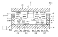
1 is a schematic perspective view showing a basic structure 1 of a force sensor according to a first embodiment of the present invention, FIG. 2 is a schematic plan view showing the basic structure 1 of FIG. 1, and FIG. FIG. 3 is a sectional view taken along line [3]-[3] of FIG. 2. In FIG. 2, the X axis is defined in the horizontal direction, the Y axis is defined in the vertical direction, and the Z axis is defined in the depth direction. In this specification, the Z-axis positive direction is referred to as an upward direction, and the Z-axis negative direction is referred to as a downward direction. Further, in the present specification, the X-axis positive rotation means a rotation direction in which the right-hand screw is rotated in order to advance the right-hand screw in the X-axis positive direction, and the X-axis negative rotation is the reverse rotation direction. To mean. The method of defining the rotation direction is the same for the Y axis and the Z axis.

図1乃至図3に示すように、基本構造1は、XY平面と平行な上面を有する円盤状の固定体10と、力ないしモーメントの作用を受けることにより固定体10に対して相対移動する円盤状の受力体20と、固定体10及び受力体20に接続され、固定体10に対する受力体20の相対移動によって弾性変形を生じる円環状の変形体40と、を備えている。固定体10、受力体20及び変形体40は、互いに同心であり、同一の外径を有している。なお、図2では、変形体40を明確に図示するため、受力体20の図示を省略してある。   As shown in FIGS. 1 to 3, the basic structure 1 includes a disk-shaped fixed body 10 having an upper surface parallel to the XY plane, and a disk that moves relative to the fixed body 10 when subjected to a force or moment. The force receiving body 20 and the fixed body 10 and the annular deformable body 40 connected to the force receiving body 20 and elastically deformed by the relative movement of the force receiving body 20 with respect to the fixed body 10. The fixed body 10, the force receiving body 20, and the deformable body 40 are concentric with each other and have the same outer diameter. In FIG. 2, the force receiving body 20 is not shown in order to clearly show the deformable body 40.

本実施の形態による基本構造1は、変形体40と固定体10との間に形成されている間隙の所定位置に容量素子を配置し、この容量素子に所定の検出回路50(図12参照)を接続することにより、力覚センサとして機能することになる。検出回路50は、容量素子の静電容量値の変動量に基づいて、作用した力ないしモーメントを計測するためのものである。容量素子の具体的な配置態様、及び、作用した力ないしモーメントを計測するための具体的な方法は、後述される。   In the basic structure 1 according to the present embodiment, a capacitive element is arranged at a predetermined position in the gap formed between the deformable body 40 and the fixed body 10, and a predetermined detection circuit 50 (see FIG. 12) is provided in this capacitive element. By connecting with, it will function as a force sensor. The detection circuit 50 is for measuring the applied force or moment based on the variation amount of the electrostatic capacitance value of the capacitive element. A specific arrangement mode of the capacitive element and a specific method for measuring the applied force or moment will be described later.

図1及び図2に示すように、変形体40は、全体として、XYZ三次元座標系の原点Oを中心とし、XY平面と平行に配置された円環の形状を有している。ここでは、図3に示すように、変形体40のZ軸方向の厚みの半分の位置にXY平面が存在していることとする。図3に示すように、本実施の形態の変形体40は、正方形の断面形状を有している。変形体40の材質としては、例えば金属が採用され得る。図2に示すように、変形体40は、正のX軸上に位置する第1固定部41と、負のX軸上に位置する第2固定部42と、正のY軸上に位置する第1受力部43と、負のY軸上に位置する第2受力部44と、を有している。後述されるように、各固定部41、42及び各受力部43、44は、変形体40のうち固定体10及び受力体20が接続される領域であって、変形体40の他の領域と異なる特性を有する部位ではない。したがって、各固定部41、42及び各受力部43、44の材質は、変形体40の他の領域と同一である。但し、説明の便宜上、図面においては、変形体40の他の領域とは異なる色で示してある。   As shown in FIGS. 1 and 2, the deformable body 40 as a whole has the shape of a ring centered on the origin O of the XYZ three-dimensional coordinate system and arranged parallel to the XY plane. Here, as shown in FIG. 3, it is assumed that the XY plane exists at a position half the thickness of the deformable body 40 in the Z-axis direction. As shown in FIG. 3, the deformable body 40 of the present embodiment has a square cross-sectional shape. The material of the deformable body 40 may be, for example, metal. As shown in FIG. 2, the deformable body 40 is positioned on the positive X-axis, is fixed on the positive X-axis, is fixed on the negative X-axis, and is positioned on the positive Y-axis. It has a first force receiving portion 43 and a second force receiving portion 44 located on the negative Y axis. As will be described later, each of the fixed portions 41, 42 and each of the force receiving portions 43, 44 is an area of the deformable body 40 to which the fixed body 10 and the force receiving body 20 are connected, and other of the deformable body 40. It is not a part that has different characteristics from the region. Therefore, the materials of the fixing portions 41 and 42 and the force receiving portions 43 and 44 are the same as those of the other regions of the deformable body 40. However, for convenience of description, in the drawings, the color is shown different from the other regions of the deformable body 40.

図1乃至図3に示すように、変形体40は、更に、第1固定部41と第1受力部43との間(XY平面の第1象限)に位置する第1変形部45と、第1受力部43と第2固定部42との間(XY平面の第2象限)に位置する第2変形部46と、第2固定部42と第2受力部44との間(XY平面の第3象限)に位置する第3変形部47と、第2受力部44と第1固定部41との間(XY平面の第4象限)に位置する第4変形部48と、を有している。各変形部45〜48の両端は、隣接する固定部41、42及び受力部43、44にそれぞれ一体的に連結されている。このような構造によって、受力部43,44に作用した力ないしモーメントが確実に各変形部45〜48に伝達され、これによって、当該作用した力ないしモーメントに応じた弾性変形が各変形部45〜48に生じるようになっている。   As shown in FIGS. 1 to 3, the deformable body 40 further includes a first deformable portion 45 located between the first fixed portion 41 and the first force receiving portion 43 (first quadrant of the XY plane). The second deformable portion 46 located between the first force receiving portion 43 and the second fixed portion 42 (the second quadrant of the XY plane), and between the second fixed portion 42 and the second force receiving portion 44 (XY A third deforming portion 47 located in the third quadrant of the plane, and a fourth deforming portion 48 located between the second force receiving portion 44 and the first fixing portion 41 (fourth quadrant of the XY plane). Have Both ends of each deforming portion 45 to 48 are integrally connected to the adjacent fixing portions 41 and 42 and force receiving portions 43 and 44, respectively. With such a structure, the force or moment acting on the force receiving portions 43, 44 is surely transmitted to each of the deforming portions 45 to 48, whereby the elastic deformation corresponding to the applied force or moment is applied to each deforming portion 45. ~ 48.

図1及び図3に示すように、基本構造1は、固定体10と変形体40とを接続する第1接続部材31及び第2接続部材32と、受力体20と変形体40とを接続する第3接続部材33及び第4接続部材34と、を更に有している。第1接続部材31は、第1固定部41の下面(図3における下方の面)と固定体10の上面とを互いに接続し、第2接続部材32は、第2固定部42の下面と固定体10の上面とを互いに接続している。第3接続部材33は、第1受力部43の上面(図3における上方の面)と受力体20の下面とを互いに接続し、第4接続部材34は、第2受力部44の上面と受力体20の下面とを互いに接続している。各接続部材31〜34は、実質的に剛体とみなせる程度の剛性を有している。このため、受力体20に作用した力ないしモーメントは、効果的に各変形部45〜48に弾性変形を生じさせることになる。   As shown in FIGS. 1 and 3, the basic structure 1 connects the first connecting member 31 and the second connecting member 32 that connect the fixed body 10 and the deformable body 40, and the force receiving body 20 and the deformable body 40. The third connecting member 33 and the fourth connecting member 34 are further provided. The first connecting member 31 connects the lower surface (the lower surface in FIG. 3) of the first fixing portion 41 and the upper surface of the fixing body 10 to each other, and the second connecting member 32 fixes the lower surface of the second fixing portion 42. The upper surface of the body 10 is connected to each other. The third connecting member 33 connects the upper surface (upper surface in FIG. 3) of the first force receiving portion 43 and the lower surface of the force receiving body 20 to each other, and the fourth connecting member 34 connects the second force receiving portion 44. The upper surface and the lower surface of the force receiving body 20 are connected to each other. Each of the connecting members 31 to 34 has a rigidity that can be regarded as a substantially rigid body. Therefore, the force or the moment acting on the force receiving body 20 effectively causes the deformation portions 45 to 48 to elastically deform.

更に、図1及び図3に示すように、変形体40の各変形部45〜48は、Z軸負方向に膨出するように湾曲した湾曲部45c〜48cを有している。図示される例では、各変形部45〜48が全体として湾曲部45c〜48cを形成している。このため、図1乃至図3では、変形部の符号45〜48と湾曲部の符号45c〜48cとを併記してある。このことは、後述される他の実施の形態でも同様である。本実施の形態の変形体40では、図3に示すように、第1湾曲部45cのうち最も下方(Z軸負方向)に位置する部位が、第1固定部41から変形体40の周方向に沿って反時計回りに45°だけ周回した位置に存在している。そして、第1湾曲部45cの、第1固定部41から前記最も下方に位置する部位第に至るまでの形状は、第1受力部43から前記最も下方に位置する部位に至るまでの形状と同一である。換言すれば、第1湾曲部45cは、変形体40の周方向において、前記最も下方に位置する部位に関して対称的な形状を有している。   Further, as shown in FIGS. 1 and 3, each of the deformable portions 45 to 48 of the deformable body 40 has curved portions 45c to 48c that are curved so as to bulge in the Z axis negative direction. In the illustrated example, the respective deforming portions 45 to 48 form the curved portions 45c to 48c as a whole. Therefore, in FIGS. 1 to 3, reference numerals 45 to 48 of the deforming portion and reference numerals 45c to 48c of the bending portion are shown together. This also applies to other embodiments described later. In the deformable body 40 of the present embodiment, as shown in FIG. 3, a portion of the first bending portion 45c located at the lowermost position (Z-axis negative direction) extends from the first fixing portion 41 in the circumferential direction of the deformable body 40. It is located at a position that is rotated by 45 ° counterclockwise along. Further, the shape of the first bending portion 45c from the first fixing portion 41 to the portion at the lowest position is the shape from the first force receiving portion 43 to the portion at the lowest position. It is the same. In other words, the first bending portion 45c has a symmetrical shape with respect to the lowermost portion in the circumferential direction of the deformable body 40.

このことは、残りの3つの湾曲部46c、47c、48cにおいても、同様である。すなわち、第2湾曲部46cは、最も下方に位置する部位が第1受力部43から変形体40の周方向に沿って反時計回りに45°だけ周回した位置に存在しており、且つ、変形体40の周方向においてこの最も下方に位置する部位に関して対称的な形状を有している。第3湾曲部47cは、最も下方に位置する部位が第2固定部42から変形体40の周方向に沿って反時計回りに45°だけ周回した位置に存在しており、且つ、変形体40の周方向においてこの最も下方に位置する部位に関して対称的な形状を有している。第4湾曲部48cは、最も下方に位置する部位が第2受力部44から変形体40の周方向に沿って反時計回りに45°だけ周回した位置に存在しており、変形体40の周方向においてこの最も下方に位置する部位に関して対称的な形状を有している。   This also applies to the remaining three curved portions 46c, 47c, 48c. That is, the second curved portion 46c is present at a position where the lowermost portion is rotated from the first force receiving portion 43 by 45 ° counterclockwise along the circumferential direction of the deformable body 40, and The deformable body 40 has a symmetrical shape with respect to the lowermost portion in the circumferential direction. The third curved portion 47c is located at a position where the lowermost portion is rotated from the second fixing portion 42 in the counterclockwise direction by 45 ° along the circumferential direction of the deformable body 40, and the deformable body 40c. It has a symmetrical shape with respect to the lowermost part in the circumferential direction. The fourth curved portion 48c is located at a position where the lowermost portion is rotated from the second force receiving portion 44 by 45 ° counterclockwise along the circumferential direction of the deformable body 40. It has a symmetrical shape with respect to the lowermost portion in the circumferential direction.

結局、図2に示すように、XY平面上に、原点Oを通りX軸およびY軸に対して45°をなすV軸およびW軸を定義すると、第1湾曲部45cは、正のV軸に関して対称的であり、第2湾曲部46cは、正のW軸に関して対称的であり、第3湾曲部47cは、負のV軸に関して対称的であり、第4湾曲部48cは、負のW軸に関して対称的である。   After all, as shown in FIG. 2, if the V axis and the W axis that pass through the origin O and form 45 ° with respect to the X axis and the Y axis are defined on the XY plane, the first bending portion 45c will have the positive V axis. Is symmetrical about the second curved portion 46c is symmetrical about the positive W axis, the third curved portion 47c is symmetrical about the negative V axis, and the fourth curved portion 48c is negative W. It is symmetrical about an axis.

図2及び図3に示すように、基本構造1には、各湾曲部45c〜48cの最も下方に位置する部位に、すなわちZ軸方向から見て各湾曲部45c〜48cがV軸及びW軸と重なる部位に、当該各湾曲部45c〜48cに生じる弾性変形を検出するための検出部位A1〜A4が規定されている。なお、図2では、検出部位A1〜A4が変形体40の上面(手前側の面)に設けられているように示されているが、実際は、変形体40の下面(奥側の面)に設けられている(図3参照)。   As shown in FIG. 2 and FIG. 3, in the basic structure 1, the bending portions 45c to 48c are located at the lowest position of the bending portions 45c to 48c, that is, the bending portions 45c to 48c are viewed from the Z-axis direction. Detection portions A1 to A4 for detecting elastic deformations occurring in the respective curved portions 45c to 48c are defined in the portions overlapping with. In addition, in FIG. 2, the detection parts A1 to A4 are illustrated as being provided on the upper surface (front side surface) of the deformable body 40, but actually, on the lower surface (back side surface) of the deformable body 40. It is provided (see FIG. 3).

< 1−2. 基本構造の作用 >
次に、このような基本構造1の作用について説明する。
<1-2. Action of basic structure >
Next, the operation of the basic structure 1 will be described.

(1−2−1. 基本構造1にX軸まわりのモーメントMxが作用した場合)
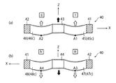
図4は、図1の基本構造1に対してX軸正まわりのモーメント+Mxが作用したときに、各湾曲部45c〜48cに生じる弾性変形を説明するための概略平面図である。また、図5は、図4の概略断面図である。図5(a)は、図4の[5a]−[5a]線断面図であり、図5(b)は、図4の[5b]−[5b]線断面図である。なお、図4及び図5において、黒塗りの太い矢印は、作用する力ないしモーメントを示しており、白抜きの太い矢印は、検出部位A1〜A4の変位の方向を示している。このことは、他の図においても同様である。
(1-2-1. When the moment Mx about the X axis acts on the basic structure 1)
FIG. 4 is a schematic plan view for explaining elastic deformation that occurs in each of the bending portions 45c to 48c when a moment + Mx about the X-axis is applied to the basic structure 1 of FIG. 5 is a schematic sectional view of FIG. 5A is a sectional view taken along the line [5a]-[5a] in FIG. 4, and FIG. 5B is a sectional view taken along the line [5b]-[5b] in FIG. 4 and 5, the thick black arrow indicates the acting force or moment, and the thick white arrow indicates the direction of displacement of the detection parts A1 to A4. This also applies to the other figures.

図4に示すように、受力体20(図1及び図3参照)を介して基本構造1にX軸正まわりのモーメント+Mxが作用すると、変形体40の第1受力部43に対してZ軸正方向(図5(a)における上方向)の力が作用し、第2受力部44に対してZ軸負方向(図5(b)における下方向)の力が作用する。図4において、第1受力部43に付されている、黒点を丸で囲んだ記号は、Z軸負方向からZ軸正方向に向かって力が作用することを示しており、第2受力部44に付されている、×印を丸で囲んだ記号は、Z軸正方向からZ軸負方向に向かって力が作用することを示している。これらの記号の意味は、図6、図8及び図10においても同様である。   As shown in FIG. 4, when the moment + Mx about the positive X axis acts on the basic structure 1 via the force receiving body 20 (see FIGS. 1 and 3), the basic force 1 is applied to the first force receiving portion 43 of the deformable body 40. A force in the Z-axis positive direction (upward direction in FIG. 5A) acts, and a force in the Z-axis negative direction (downward direction in FIG. 5B) acts on the second force receiving portion 44. In FIG. 4, a symbol surrounded by a black dot attached to the first force receiving portion 43 indicates that a force acts from the Z axis negative direction to the Z axis positive direction, and the second force receiving portion 43 The symbol surrounded by a circle and attached to the force portion 44 indicates that the force acts from the Z-axis positive direction to the Z-axis negative direction. The meanings of these symbols are the same in FIGS. 6, 8 and 10.

このとき、図5(a)及び図5(b)に示すように、第1〜第4湾曲部45c〜48cには次のような弾性変形が生じる。すなわち、第1受力部43に作用するZ軸正方向の力によって当該第1受力部43が上方に移動するため、第1湾曲部45c及び第2湾曲部46cのうち第1受力部43に連結されている端部が上方に移動させられる。これにより、図5(a)に示すように、第1湾曲部45c及び第2湾曲部46cは、第1及び第2固定部41、42に連結されている端部を除き、全体的に上方に移動する。すなわち、第1検出部位A1及び第2検出部位A2は、共に上方に移動する。他方、第2受力部44に作用するZ軸負方向の力によって当該第2受力部44が下方に移動するため、第3湾曲部47c及び第4湾曲部48cのうち第2受力部44に連結されている端部が下方に移動させられる。これにより、図5(b)に示すように、第3湾曲部47c及び第4湾曲部48cは、第1及び第2固定部41、42に連結されている端部を除き、全体的に下方に移動する。すなわち、第3検出部位A3及び第4検出部位A4は、共に下方に移動する。   At this time, as shown in FIGS. 5A and 5B, the following elastic deformation occurs in the first to fourth bending portions 45c to 48c. That is, since the first force receiving portion 43 moves upward due to the Z-axis positive direction force acting on the first force receiving portion 43, the first force receiving portion of the first bending portion 45c and the second bending portion 46c. The end connected to 43 is moved upward. As a result, as shown in FIG. 5A, the first bending portion 45c and the second bending portion 46c are entirely upward except for the end portions connected to the first and second fixing portions 41 and 42. Move to. That is, both the first detection portion A1 and the second detection portion A2 move upward. On the other hand, since the second force receiving portion 44 moves downward due to the Z-axis negative direction force acting on the second force receiving portion 44, the second force receiving portion of the third bending portion 47c and the fourth bending portion 48c. The end connected to 44 is moved downward. As a result, as shown in FIG. 5B, the third bending portion 47c and the fourth bending portion 48c are entirely downward except for the end portions connected to the first and second fixing portions 41 and 42. Move to. That is, both the third detection portion A3 and the fourth detection portion A4 move downward.

このような移動は、図4においては、各検出部位A1〜A4の位置に、丸で囲んだ「+」または「−」の記号を付して表されている。すなわち、丸で囲んだ「+」の記号が付された検出部位は、湾曲部の弾性変形によってZ軸正方向に変位し、丸で囲んだ「−」の記号が付された検出部位は、湾曲部の弾性変形によってZ軸負方向に変位する。このことは、図6、図8及び図10においても同様である。   Such movement is shown in FIG. 4 by adding a circled symbol “+” or “−” to the positions of the detection sites A1 to A4. That is, the detection part surrounded by a circle and marked "+" is displaced in the Z-axis positive direction by the elastic deformation of the curved portion, and the detection part surrounded by a circle and marked "-" is It is displaced in the negative direction of the Z-axis due to the elastic deformation of the curved portion. This also applies to FIGS. 6, 8 and 10.

結局、基本構造1の受力体20に対してX軸正まわりのモーメント+Mxが作用すると、第1及び第2検出部位A1、A2と固定体10(図3参照)の上面との離間距離は、共に増大し、第3及び第4検出部位A3、A4と固定体10の上面との離間距離は、共に減少する。   After all, when the moment + Mx about the X-axis is applied to the force receiving body 20 of the basic structure 1, the distance between the first and second detection portions A1 and A2 and the upper surface of the fixed body 10 (see FIG. 3) is reduced. , Both increase, and the distance between the third and fourth detection portions A3, A4 and the upper surface of the fixed body 10 decreases.

図示されていないが、基本構造1の受力体20にX軸負まわりのモーメント−Mxが作用した場合には、各検出部位A1〜A4の移動方向は、上述した方向とは逆になる。すなわち、X軸負まわりのモーメント−Mxの作用によって、第1及び第2検出部位A1、A2と固定体10(図2参照)の上面との離間距離は、共に減少し、第3及び第4検出部位A3、A4と固定体10の上面との離間距離は、共に増大する。   Although not shown, when the negative force X-axis moment −Mx acts on the force receiving body 20 of the basic structure 1, the moving directions of the respective detection portions A1 to A4 are opposite to the above-described directions. That is, the distance between the first and second detection portions A1 and A2 and the upper surface of the fixed body 10 (see FIG. 2) is reduced by the action of the negative moment about the X axis −Mx, and the third and fourth portions are reduced. The distances between the detection parts A3 and A4 and the upper surface of the fixed body 10 both increase.

(1−2−2. 基本構造1にY軸まわりのモーメントMyが作用した場合)
図6は、図1の基本構造1に対してY軸正まわりのモーメント+Myが作用したときに、各湾曲部45c〜48cに生じる弾性変形を説明するための概略平面図である。また、図7は、図6の概略断面図である。図7(a)は、図6の[7a]−[7a]線断面図であり、図7(b)は、図6の[7b]−[7b]線断面図である。
(1-2-2. When the moment My about the Y axis acts on the basic structure 1)
FIG. 6 is a schematic plan view for explaining elastic deformation that occurs in each of the bending portions 45c to 48c when a moment + My about the Y axis is applied to the basic structure 1 of FIG. FIG. 7 is a schematic sectional view of FIG. 7A is a sectional view taken along the line [7a]-[7a] in FIG. 6, and FIG. 7B is a sectional view taken along the line [7b]-[7b] in FIG.

図6及び図7に示すように、受力体20(図1及び図3参照)を介して基本構造1に対してY軸正まわりのモーメント+Myが作用すると、変形体40の第1及び第2受力部43、44のX軸負側の領域にはZ軸正方向の力が作用し、第1及び第2受力部43、44のX軸正側の領域にはZ軸負方向の力が作用する。   As shown in FIGS. 6 and 7, when the moment + My about the Y axis in the normal direction acts on the basic structure 1 via the force receiving body 20 (see FIGS. 1 and 3), the first and The force in the Z-axis positive direction acts on the regions on the X-axis negative side of the second force receiving units 43 and 44, and the Z-axis negative direction on the regions on the X-axis positive side of the first and second force receiving units 43 and 44. Force of.

このとき、図7(a)及び図7(b)に示すように、第1〜第4湾曲部45c〜48cには次のような弾性変形が生じる。すなわち、第1受力部43のX軸正側(図7(a)における右側)に作用するZ軸負方向の力によって当該X軸正側の領域が下方に移動するため、第1湾曲部45cのうち第1受力部43に連結されている端部が下方に移動させられる。これにより、図7(a)に示すように、第1湾曲部45cは、第1固定部41に連結されている端部を除き、全体的に下方に移動する。すなわち、第1検出部位A1は、下方に移動する。他方、第1受力部43のX軸負側(図7(a)における左側)に作用するZ軸正方向の力によって当該X軸負側の領域が上方に移動するため、第2湾曲部46cのうち第1受力部43に連結されている端部が上方に移動する。これにより、図7(a)に示すように、第2湾曲部46cは、第2固定部42に連結されている端部を除き、全体的に上方に移動する。すなわち、第2検出部位A2は、上方に移動する。   At this time, as shown in FIGS. 7A and 7B, the following elastic deformation occurs in the first to fourth bending portions 45c to 48c. That is, the region in the X-axis positive side moves downward due to the force in the Z-axis negative direction that acts on the X-axis positive side (right side in FIG. 7A) of the first force receiving portion 43, and thus the first bending portion. Of 45c, the end connected to the first force receiving portion 43 is moved downward. As a result, as shown in FIG. 7A, the first bending portion 45c moves downward as a whole except for the end portion connected to the first fixing portion 41. That is, the first detection portion A1 moves downward. On the other hand, the area on the negative side of the X-axis moves upward due to the force in the positive direction of the Z-axis that acts on the negative side of the X-axis (the left side in FIG. 7A) of the first force receiving portion 43, so the second bending portion An end portion of 46c connected to the first force receiving portion 43 moves upward. As a result, as shown in FIG. 7A, the second bending portion 46c moves upward as a whole except for the end portion connected to the second fixing portion 42. That is, the second detection portion A2 moves upward.

また、図7(b)に示すように、第2受力部44のX軸負側(図7(b)における右側)に作用するZ軸正方向の力によって当該X軸負側の領域が上方に移動するため、第3湾曲部47cのうち第2受力部44に連結されている端部が上方に移動させられる。これにより、図7(b)に示すように、第3湾曲部47cは、第2固定部42に連結されている端部を除き、全体的に上方に移動する。すなわち、第3検出部位A3は、上方に移動する。   Further, as shown in FIG. 7B, the region on the X-axis negative side is caused by the force in the Z-axis positive direction acting on the X-axis negative side of the second force receiving portion 44 (right side in FIG. 7B). Since it moves upward, the end portion of the third bending portion 47c connected to the second force receiving portion 44 is moved upward. As a result, as shown in FIG. 7B, the third bending portion 47c moves upward as a whole except for the end portion connected to the second fixing portion 42. That is, the third detection portion A3 moves upward.

他方、図7(b)に示すように、第2受力部44のX軸正側(図7(b)における左側)に作用するZ軸負方向の力によって当該X軸正側の領域が下方に移動するため、第4湾曲部48cのうち第2受力部44に連結されている端部が下方に移動させられる。これにより、図7(b)に示すように、第4湾曲部48cは、第1固定部41に連結されている端部を除き、全体的に下方に移動する。すなわち、第4検出部位A4は、下方に移動する。   On the other hand, as shown in FIG. 7B, the area on the X-axis positive side is caused by the Z-axis negative direction force acting on the X-axis positive side (left side in FIG. 7B) of the second force receiving portion 44. Since it moves downward, the end portion of the fourth bending portion 48c that is connected to the second force receiving portion 44 is moved downward. As a result, as shown in FIG. 7B, the fourth bending portion 48c moves downward as a whole except for the end portion connected to the first fixing portion 41. That is, the fourth detection portion A4 moves downward.

結局、基本構造1の受力体20に対してY軸正まわりのモーメント+Myが作用すると、第1及び第4検出部位A1、A4と固定体10(図3参照)の上面との離間距離は、共に減少し、第2及び第3検出部位A2、A3と固定体10の上面との離間距離は、共に増大する。   After all, when the moment + My about the Y axis in the normal direction acts on the force receiving body 20 of the basic structure 1, the distance between the first and fourth detection portions A1 and A4 and the upper surface of the fixed body 10 (see FIG. 3) becomes smaller. , Both decrease, and the distance between the second and third detection portions A2, A3 and the upper surface of the fixed body 10 increases together.

図示されていないが、基本構造1の受力体20にY軸負まわりのモーメント−Myが作用した場合には、各検出部位A1〜A4の移動方向は、上述した方向とは逆になる。すなわち、Y軸負まわりのモーメント−Myの作用によって、第1及び第4検出部位A1、A4と固定体10(図3参照)の上面との離間距離は、共に増大し、第2及び第3検出部位A2、A3と固定体10の上面との離間距離は、共に減少する。   Although not shown, when the negative force Y about the Y axis acts on the force receiving body 20 of the basic structure 1, the moving directions of the respective detection portions A1 to A4 are opposite to the above-described directions. That is, the distance between the first and fourth detection portions A1 and A4 and the upper surface of the fixed body 10 (see FIG. 3) is increased by the action of the negative moment about the Y axis −My, and the second and third detection portions A1 and A4 increase. The distance between the detection parts A2 and A3 and the upper surface of the fixed body 10 is reduced.

(1−2−3. 基本構造1にZ軸まわりのモーメントMzが作用した場合)
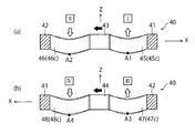
図8は、図1の基本構造1に対してZ軸正まわりのモーメント+Mzが作用したときに、各湾曲部45c〜48cに生じる弾性変形を説明するための概略平面図である。また、図9は、図8の概略断面図である。図9(a)は、図8の[9a]−[9a]線断面図であり、図9(b)は、図8の[9b]−[9b]線断面図である。
(1-2-3. When the moment Mz about the Z axis acts on the basic structure 1)
FIG. 8 is a schematic plan view for explaining elastic deformation that occurs in each of the bending portions 45c to 48c when a moment + Mz about the Z-axis is applied to the basic structure 1 of FIG. 9 is a schematic sectional view of FIG. 9A is a sectional view taken along the line [9a]-[9a] in FIG. 8, and FIG. 9B is a sectional view taken along the line [9b]-[9b] in FIG.

図8に示すように、受力体20(図1及び図3参照)を介して基本構造1に対してZ軸正まわりのモーメント+Mzが作用すると、変形体40の第1受力部43に対してX軸負方向(図8における左方向)の力が作用し、第2受力部44に対してX軸正方向(図8における右方向)の力が作用する。   As shown in FIG. 8, when a moment + Mz about the Z-axis is applied to the basic structure 1 via the force receiving body 20 (see FIGS. 1 and 3), the first force receiving portion 43 of the deformable body 40 is affected. On the other hand, a force in the X-axis negative direction (leftward in FIG. 8) acts, and a force in the X-axis positive direction (rightward in FIG. 8) acts on the second force receiving portion 44.

このとき、図9(a)及び図9(b)に示すように、第1〜第4湾曲部45c〜48cには次のような弾性変形が生じる。すなわち、第1受力部43に作用するX軸負方向の力によって当該第1受力部43がX軸負方向に移動するため、第1湾曲部45cには、X軸方向に沿った引張力が作用する。これにより、第1湾曲部45cは、その両端部のZ座標値を維持したまま曲率半径が大きくなるように弾性変形する。すなわち、第1検出部位A1は、上方に移動する。他方、第1受力部43がX軸負方向に移動することにより、第2湾曲部46cには、X軸方向に沿った圧縮力が作用する。これにより、第2湾曲部46cは、その両端部のZ座標値を維持したまま曲率半径が小さくなるように弾性変形する。すなわち、第2検出部位A2は、下方に移動する。   At this time, as shown in FIGS. 9A and 9B, the following elastic deformation occurs in the first to fourth bending portions 45c to 48c. That is, since the first force receiving portion 43 moves in the negative direction of the X axis by the force in the negative direction of the X axis acting on the first force receiving portion 43, the first bending portion 45c has a tensile force along the X axis direction. Power acts. As a result, the first bending portion 45c elastically deforms so that the radius of curvature becomes large while maintaining the Z coordinate values of both ends thereof. That is, the first detection portion A1 moves upward. On the other hand, when the first force receiving portion 43 moves in the negative direction of the X axis, a compressive force along the X axis direction acts on the second bending portion 46c. As a result, the second bending portion 46c elastically deforms so that the radius of curvature becomes smaller while maintaining the Z coordinate values of both ends thereof. That is, the second detection portion A2 moves downward.

また第2受力部44に作用するX軸正方向の力によって当該第2受力部44がX軸正方向に移動するため、第3湾曲部47cには、X軸方向に沿った引張力が作用する。これにより、第3湾曲部47cは、その両端部のZ座標値を維持したまま曲率半径が大きくなるように弾性変形する。すなわち、第3検出部位A3は、上方に移動する。他方、第2受力部44がX軸正方向に移動することにより、第4湾曲部48cには、X軸方向に沿った圧縮力が作用する。これにより、第4湾曲部48cは、その両端部のZ座標値を維持したまま曲率半径が小さくなるように弾性変形する。すなわち、第4検出部位A4は、下方に移動する。   Further, since the second force receiving portion 44 moves in the X axis positive direction due to the force in the X axis positive direction acting on the second force receiving portion 44, the third bending portion 47c has a tensile force along the X axis direction. Works. As a result, the third bending portion 47c elastically deforms so that the radius of curvature becomes large while maintaining the Z coordinate values of both ends thereof. That is, the third detection portion A3 moves upward. On the other hand, when the second force receiving portion 44 moves in the positive direction of the X axis, a compressive force along the X axis direction acts on the fourth bending portion 48c. As a result, the fourth bending portion 48c elastically deforms so that the radius of curvature becomes smaller while maintaining the Z coordinate values at both ends thereof. That is, the fourth detection portion A4 moves downward.

結局、基本構造1の受力体20に対してZ軸正まわりのモーメント+Mzが作用すると、第1及び第3検出部位A1、A3と固定体10の上面との離間距離は、共に増大し、第2及び第4検出部位A2、A4と固定体10(図2参照)の上面との離間距離は、共に減少する。   Eventually, when the moment + Mz about the Z-axis is applied to the force receiving body 20 of the basic structure 1, the distance between the first and third detection portions A1 and A3 and the upper surface of the fixed body 10 increases, The distance between the second and fourth detection parts A2 and A4 and the upper surface of the fixed body 10 (see FIG. 2) is both reduced.

図示されていないが、基本構造1の受力体20にZ軸負まわりのモーメント−Mzが作用した場合には、各検出部位A1〜A4の移動方向は、上述した方向とは逆になる。すなわち、Z軸負まわりのモーメント−Mzの作用によって、第1及び第3検出部位A1、A3と固定体10の上面との離間距離は、共に減少し、第2及び第4検出部位A2、A4と固定体10(図2参照)の上面との離間距離は、共に増大する。   Although not shown, when the negative force about the Z-axis -Mz acts on the force receiving body 20 of the basic structure 1, the moving directions of the detection parts A1 to A4 are opposite to the above-described directions. That is, the distance between the first and third detection portions A1 and A3 and the upper surface of the fixed body 10 is reduced by the action of the negative moment about the Z-axis −Mz, and the second and fourth detection portions A2 and A4 are reduced. The distance between the upper surface of the fixed body 10 and the upper surface of the fixed body 10 (see FIG. 2) both increases.

(1−2−4. 基本構造1にZ方向の力Fzが作用した場合)
次に、図10は、図1の基本構造1に対してZ軸正方向の力+Fzが作用したときに、各湾曲部45c〜48cに生じる弾性変形を説明するための概略平面図である。また、図11は、図10の概略断面図である。図11(a)は、図10の[11a]−[11a]線断面図であり、図11(b)は、図10の[11b]−[11b]線断面図である。
(1-2-4. When the force Fz in the Z direction acts on the basic structure 1)
Next, FIG. 10 is a schematic plan view for explaining elastic deformation that occurs in each of the bending portions 45c to 48c when the force + Fz in the Z-axis positive direction acts on the basic structure 1 of FIG. Further, FIG. 11 is a schematic sectional view of FIG. 10. 11A is a sectional view taken along the line [11a]-[11a] of FIG. 10, and FIG. 11B is a sectional view taken along the line [11b]-[11b] of FIG.

図10及び図11に示すように、受力体20(図1及び図3参照)を介して基本構造1に対してZ軸正方向の力+Fzが作用すると、変形体40の第1及び第2受力部43、44にはZ軸正方向の力が作用する。   As shown in FIGS. 10 and 11, when the force + Fz in the Z-axis positive direction acts on the basic structure 1 via the force receiving body 20 (see FIGS. 1 and 3), the first and The force in the Z-axis positive direction acts on the two force receiving portions 43 and 44.

このとき、図11(a)及び図11(b)に示すように、第1〜第4各湾曲部45c〜48cには次のような弾性変形が生じる。すなわち、第1及び第2受力部43、44に作用するZ軸正方向の力によって各受力部43、44が上方に移動するため、各湾曲部45c〜48cのうち第1及び第2受力部43、44に連結されている各端部が上方に移動させられる。これにより、図11(a)及び図11(b)に示すように、各検出部位A1〜A4は、上方に移動する。   At this time, as shown in FIGS. 11A and 11B, the following elastic deformation occurs in the first to fourth curved portions 45c to 48c. That is, since the force receiving portions 43 and 44 move upward due to the Z-axis positive direction force acting on the first and second force receiving portions 43 and 44, the first and second bending portions 45c to 48c are first and second. Each end connected to the force receiving portions 43 and 44 is moved upward. As a result, as shown in FIGS. 11A and 11B, the detection parts A1 to A4 move upward.

結局、基本構造1の受力体20に対してZ軸正方向の力+Fzが作用すると、第1〜第4検出部位A1〜A4と固定体10(図2参照)の上面との離間距離は、全て増大する。   After all, when the force + Fz in the Z-axis positive direction acts on the force receiving body 20 of the basic structure 1, the separation distance between the first to fourth detection portions A1 to A4 and the upper surface of the fixed body 10 (see FIG. 2) becomes smaller. , All increase.

図示されていないが、基本構造1の受力体20にZ軸負方向の力−Fzが作用した場合には、各検出部位A1〜A4の移動方向は、上述した方向とは逆になる。すなわち、Z軸負方向の力−Fzの作用によって、第1〜第4検出部位A1〜A4と固定体10(図2参照)の上面との離間距離は、全て減少する。   Although not shown, when a force −Fz in the negative Z-axis direction acts on the force receiving body 20 of the basic structure 1, the moving directions of the detection parts A1 to A4 are opposite to the above-described directions. That is, the distance between the first to fourth detection portions A1 to A4 and the upper surface of the fixed body 10 (see FIG. 2) is all reduced by the action of the force −Fz in the negative Z-axis direction.

< 1−3. 容量素子型の力覚センサ >
(1−3−1. 力覚センサの構成)
§1−1.及び§1−2.において詳述した基本構造1は、容量素子型の力覚センサ1cとして好適に使用することができる。ここでは、このような力覚センサ1cについて、以下詳細に説明する。
<1-3. Capacitive element type force sensor >
(1-3-1. Structure of force sensor)
§1-1. And §1-2. The basic structure 1 described in detail above can be suitably used as the capacitive element type force sensor 1c. Here, such a force sensor 1c will be described in detail below.

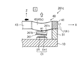
図12は、図1の基本構造1を利用した力覚センサ1cを示す概略平面図であり、図13は、図12の[13]−[13]線断面図である。なお、図13では、変形体40を明確に図示するため、受力体20の図示を省略してある。   12 is a schematic plan view showing a force sensor 1c utilizing the basic structure 1 of FIG. 1, and FIG. 13 is a sectional view taken along the line [13]-[13] of FIG. In FIG. 13, the force receiving body 20 is not shown in order to clearly show the deformable body 40.

図12及び図13に示すように、力覚センサ1cは、図1の基本構造1の検出部位A1〜A4に、各1つの容量素子C1〜C4が配置されることにより、構成されている。具体的には、図13に示すように、力覚センサ1cは、第1検出部位A1に配置された第1変位電極Em1と、第1変位電極Em1に対向して配置され、固定体10に対して相対移動しない第1固定電極Ef1と、を有している。これらの電極Em1、Ef1は、第1容量素子C1を構成している。更に、図13に示すように、力覚センサ1cは、第2検出部位A2に配置された第2変位電極Em2と、第2変位電極Em2に対向して配置され、固定体10に対して相対移動しない第2固定電極Ef2と、を有している。これらの電極Em2、Ef2は、第2容量素子C2を構成している。   As shown in FIGS. 12 and 13, the force sensor 1c is configured by disposing one capacitive element C1 to C4 at each of the detection sites A1 to A4 of the basic structure 1 of FIG. Specifically, as shown in FIG. 13, the force sensor 1c is disposed on the fixed body 10 so as to face the first displacement electrode Em1 disposed at the first detection site A1 and the first displacement electrode Em1. It has the 1st fixed electrode Ef1 which does not move relatively with respect to it. These electrodes Em1 and Ef1 form a first capacitive element C1. Further, as shown in FIG. 13, the force sensor 1c is arranged so as to face the second displacement electrode Em2 arranged at the second detection site A2 and the second displacement electrode Em2, and is relatively fixed to the fixed body 10. It has the 2nd fixed electrode Ef2 which does not move. These electrodes Em2 and Ef2 form a second capacitance element C2.

図示されていないが、力覚センサ1cは、第3検出部位A3に配置された第3変位電極Em3と、第3変位電極Em3に対向して配置され、固定体10に対して相対移動しない第3固定電極Ef3と、第4検出部位A4に配置された第4変位電極Em4と、第4変位電極Em4に対向して配置され、固定体10に対して相対移動しない第4固定電極Ef4と、を有している。電極Em3及び電極Ef3は、第3容量素子C3を構成しており、電極Em4及び電極Ef4は、第4容量素子C4を構成している。   Although not shown, the force sensor 1c is disposed so as to face the third displacement electrode Em3 and the third displacement electrode Em3 disposed at the third detection site A3, and does not move relative to the fixed body 10. 3 fixed electrode Ef3, 4th displacement electrode Em4 arrange | positioned at 4th detection site | part A4, 4th fixed electrode Ef4 arrange | positioned facing 4th displacement electrode Em4, and does not move relative to the fixed body 10, have. The electrode Em3 and the electrode Ef3 configure a third capacitive element C3, and the electrode Em4 and the electrode Ef4 configure a fourth capacitive element C4.

図13から理解されるように、各変位電極Em1〜Em4は、対応する検出部位A1〜A4に支持された第1〜第4変形体側支持体61〜64の下面に、第1〜第4変位基板Im1〜Im4を介して支持されている。更に、各固定電極Ef1〜Ef4は、固定体10の上面に固定された固定体側支持体71〜74の上面に、第1〜第4固定基板If1〜If4を介して支持されている。各変位電極Em1〜Em4は、全て同一の面積であり、各固定電極Ef1〜Ef4も、全て同一の面積である。但し、力ないしモーメントの作用によって各容量素子C1〜C4の実効対向面積が一定の値を維持するようにするための工夫として、変位電極Em1〜Em4の電極面積は、固定電極Ef1〜Ef4の電極面積よりも大きく構成されている。この点については、後に詳述される。初期状態において、容量素子C1〜C4を構成する各1組の電極の実効対向面積及び離間距離は、全て同一である。   As can be understood from FIG. 13, the displacement electrodes Em1 to Em4 have the first to fourth displacements on the lower surfaces of the first to fourth deformable body side supports 61 to 64 supported by the corresponding detection sites A1 to A4. It is supported via the substrates Im1 to Im4. Further, each of the fixed electrodes Ef1 to Ef4 is supported on the upper surfaces of the fixed body side support bodies 71 to 74 fixed to the upper surface of the fixed body 10 via the first to fourth fixed substrates If1 to If4. The displacement electrodes Em1 to Em4 all have the same area, and the fixed electrodes Ef1 to Ef4 also have the same area. However, the electrode area of the displacement electrodes Em1 to Em4 is the electrode area of the fixed electrodes Ef1 to Ef4 as a device for maintaining the effective facing area of each of the capacitive elements C1 to C4 at a constant value by the action of force or moment. It is configured to be larger than the area. This point will be described in detail later. In the initial state, the effective facing areas and the distances between the electrodes of each pair of the capacitors C1 to C4 are the same.

更に、図12及び図13に示すように、力覚センサ1cは、変形体40の各湾曲部45c〜48cに生じる弾性変形に基づいて、受力体20に作用した力ないしモーメントを示す電気信号を出力する検出回路50を有している。図12及び図13では、各容量素子C1〜C4と検出回路50とを電気的に接続する配線は、図示が省略されている。   Further, as shown in FIGS. 12 and 13, the force sensor 1c is an electrical signal indicating a force or moment acting on the force receiving body 20 based on the elastic deformation generated in each of the bending portions 45c to 48c of the deformable body 40. It has a detection circuit 50 for outputting In FIGS. 12 and 13, the wiring that electrically connects each of the capacitive elements C1 to C4 and the detection circuit 50 is omitted.

固定体10、受力体20及び変形体40が金属などの導電材料で構成されている場合、各電極がショートしないように、第1〜第4変位基板Im1〜Im4及び第1〜第4固定基板If1〜If4は、絶縁体で構成される必要がある。   When the fixed body 10, the force receiving body 20, and the deformable body 40 are made of a conductive material such as metal, the first to fourth displacement substrates Im1 to Im4 and the first to fourth fixed bodies are arranged so that the electrodes are not short-circuited. The substrates If1 to If4 need to be made of an insulator.

(1−3−2. 力覚センサ1cにX軸まわりのモーメントMxが作用したときの、各容量素子の静電容量値の変動について)
次に、図14は、図12の力覚センサ1cに対して、力ないしモーメントが作用した時に各容量素子C1〜C4に生じる静電容量値の変動を示す図表である。
(1-3-2. Regarding fluctuation of electrostatic capacitance value of each capacitive element when moment Mx about X axis acts on force sensor 1c)
Next, FIG. 14 is a chart showing variations in the capacitance value generated in each of the capacitive elements C1 to C4 when a force or moment acts on the force sensor 1c of FIG.

まず、本実施の形態による力覚センサ1cに対して、X軸正まわりのモーメント+Mxが作用すると、§1−2−1にて説明した各検出部位A1〜A4の挙動から理解されるように、第1容量素子C1及び第2容量素子C2を構成する電極間の離間距離が、共に増大する。このため、第1容量素子C1及び第2容量素子C2の静電容量値は、共に減少する。他方、第3容量素子C3及び第4容量素子C4を構成する電極間の離間距離は、共に減少する。このため、第3容量素子C3及び第4容量素子C4の静電容量値は、共に増大する。各容量素子C1〜C4の静電容量値の変動は、図14の「Mx」の欄に纏めて示されている。この図表において、「+」は、静電容量値が増大することを示しており、「−」は、静電容量値が減少することを示している。なお、力覚センサ1cにX軸負まわりのモーメント−Mxが作用すると、各容量素子C1〜C4の静電容量値の変動は、上述した変動とは逆になる(図14のMxの欄に示す符号が全て逆になる)。   First, when the moment + Mx about the X-axis is applied to the force sensor 1c according to the present embodiment, as will be understood from the behavior of the detection parts A1 to A4 described in §1-2-1. , The distance between the electrodes forming the first capacitive element C1 and the second capacitive element C2 both increases. Therefore, the capacitance values of the first capacitive element C1 and the second capacitive element C2 both decrease. On the other hand, the distance between the electrodes forming the third capacitive element C3 and the fourth capacitive element C4 both decreases. Therefore, the capacitance values of the third capacitive element C3 and the fourth capacitive element C4 both increase. The variation of the capacitance value of each of the capacitive elements C1 to C4 is collectively shown in the column of “Mx” in FIG. In this chart, "+" indicates that the capacitance value increases, and "-" indicates that the capacitance value decreases. When the negative moment about the X-axis -Mx acts on the force sensor 1c, the variation of the capacitance value of each of the capacitive elements C1 to C4 is opposite to the variation described above (in the column of Mx in FIG. 14). All signs are reversed).

(1−3−3. 力覚センサ1cにY軸まわりのモーメントMyが作用したときの、各容量素子の静電容量値の変動について)
次に、本実施の形態による力覚センサ1cに対して、Y軸正まわりのモーメント+Myが作用すると、§1−2−2にて説明した各検出部位A1〜A4の挙動から理解されるように、第1容量素子C1及び第4容量素子C4を構成する電極間の離間距離が、共に減少する。このため、第1容量素子C1及び第4容量素子C4の静電容量値は、共に増大する。他方、第2容量素子C2及び第3容量素子C3を構成する電極間の離間距離は、共に増大する。このため、第2容量素子C2及び第3容量素子C3の静電容量値は、共に減少する。各容量素子C1〜C4の静電容量値の変動は、図14の「My」の欄に纏めて示されている。なお、力覚センサ1cにY軸負まわりのモーメント−Myが作用すると、各容量素子C1〜C4の静電容量値の変動は、上述した変動とは逆になる(図14のMyの欄に示す符号が全て逆になる)。
(1-3-3. Regarding Variation of Capacitance Value of Each Capacitance Element when Moment My about Y Axis Acts on Force Sensor 1c)
Next, when a moment + My around the Y axis acts on the force sensor 1c according to the present embodiment, it will be understood from the behavior of the detection parts A1 to A4 described in §1-2-2. In addition, the distance between the electrodes forming the first capacitive element C1 and the fourth capacitive element C4 both decreases. Therefore, the capacitance values of the first capacitive element C1 and the fourth capacitive element C4 both increase. On the other hand, the distance between the electrodes forming the second capacitive element C2 and the third capacitive element C3 both increases. Therefore, the capacitance values of the second capacitive element C2 and the third capacitive element C3 both decrease. The variation in the capacitance value of each of the capacitive elements C1 to C4 is collectively shown in the column “My” in FIG. When the negative moment about the Y-axis -My is applied to the force sensor 1c, the variation of the capacitance value of each of the capacitive elements C1 to C4 is opposite to the variation described above (in the column of My in FIG. 14). All signs are reversed).

(1−3−4. 力覚センサ1cにZ軸まわりのモーメントMzが作用したときの、各容量素子の静電容量値の変動について)
次に、本実施の形態による力覚センサ1cに対して、Z軸正まわりのモーメント+Mzが作用すると、§1−2−3にて説明した各検出部位A1〜A4の挙動から理解されるように、第1容量素子C1及び第3容量素子C3を構成する電極間の離間距離は、共に増大する。このため、第1容量素子C1及び第3容量素子C3の静電容量値は、共に減少する。他方、第2容量素子C2及び第4容量素子C4を構成する電極間の離間距離は、共に減少する。このため、第2容量素子C2及び第4容量素子C4の静電容量値は、共に増大する。各容量素子C1〜C4の静電容量値の変動は、図14の「Mz」の欄に纏めて示されている。なお、力覚センサ1cにZ軸負まわりのモーメント−Mzが作用すると、各容量素子C1〜C4の静電容量値の変動は、上述した変動とは逆になる(図14のMzの欄に示す符号が全て逆になる)。
(1-3-4. Regarding fluctuation of capacitance value of each capacitance element when moment Mz about Z axis acts on force sensor 1c)
Next, when the moment + Mz about the Z-axis is applied to the force sensor 1c according to the present embodiment, it can be understood from the behaviors of the detection parts A1 to A4 described in §1-2-3. In addition, the distance between the electrodes forming the first capacitive element C1 and the third capacitive element C3 both increases. Therefore, the capacitance values of the first capacitive element C1 and the third capacitive element C3 both decrease. On the other hand, the distance between the electrodes forming the second capacitive element C2 and the fourth capacitive element C4 both decreases. Therefore, the capacitance values of the second capacitive element C2 and the fourth capacitive element C4 both increase. The variation of the capacitance value of each of the capacitive elements C1 to C4 is collectively shown in the “Mz” column of FIG. When the negative force about the Z-axis -Mz acts on the force sensor 1c, the variation in the capacitance value of each of the capacitive elements C1 to C4 is opposite to the variation described above (in the column of Mz in FIG. 14). All signs are reversed).

(1−3−5. 力覚センサ1cにZ軸方向の力Fzが作用したときの、各容量素子の静電容量値の変動について)
次に、本実施の形態による力覚センサ1cに対して、Z軸正方向の力+Fzが作用すると、§1−2−4にて説明した各検出部位A1〜A4の挙動から理解されるように、各容量素子C1〜C4を構成する電極間の離間距離は、全て増大する。このため、容量素子C1〜C4の静電容量値は、全て減少する。各容量素子C1〜C4の静電容量値の変動は、図14の「Fz」の欄に纏めて示されている。なお、力覚センサ1cにZ軸負方向の力−Fzが作用すると、各容量素子C1〜C4の静電容量値の変動は、上述した変動とは逆になる(図14のFzの欄に示す符号が全て逆になる)。
(1-3-5. Regarding fluctuation of electrostatic capacitance value of each capacitive element when force Fz in the Z-axis direction acts on the force sensor 1c)
Next, when the force + Fz in the Z-axis positive direction acts on the force sensor 1c according to the present embodiment, it will be understood from the behavior of the detection parts A1 to A4 described in §1-2-4. In addition, the distances between the electrodes forming each of the capacitive elements C1 to C4 are all increased. Therefore, the capacitance values of the capacitive elements C1 to C4 are all reduced. The variation in the capacitance value of each of the capacitive elements C1 to C4 is collectively shown in the “Fz” column of FIG. When the force −Fz in the negative Z-axis direction acts on the force sensor 1c, the variation in the capacitance value of each of the capacitive elements C1 to C4 is opposite to the variation described above (see the Fz column in FIG. 14). All signs are reversed).

(1−3−6. 作用した力ないしモーメントの算出方法)
以上のような容量素子C1〜C4の静電容量値の変動に鑑み、検出回路50は、次の[式1]を用いて力覚センサ1cに作用したモーメントMx、My、Mz及び力Fzを算出する。[式1]において、C1〜C4は、第1〜第4容量素子C1〜C4の静電容量値の変動量を示している。
[式1]
Mx=−C1−C2+C3+C4
My=C1−C2−C3+C4
Mz=−C1+C2−C3+C4
Fz=−(C1+C2+C3+C4)
なお、力覚センサ1cに作用した力ないしモーメントが負方向である場合には、左辺のMx、My、Mz及びFzに代えて、−Mx、−My、−Mz及び−Fzとすれば良い。
(1-3-6. Method of calculating applied force or moment)
In consideration of the fluctuations in the capacitance values of the capacitive elements C1 to C4 as described above, the detection circuit 50 calculates the moments Mx, My, Mz, and the force Fz acting on the force sensor 1c using the following [Equation 1]. calculate. In [Equation 1], C1 to C4 represent variations in the capacitance values of the first to fourth capacitive elements C1 to C4.
[Formula 1]
Mx = -C1-C2 + C3 + C4
My = C1-C2-C3 + C4
Mz = -C1 + C2-C3 + C4
Fz =-(C1 + C2 + C3 + C4)
When the force or moment acting on the force sensor 1c is in the negative direction, -Mx, -My, -Mz and -Fz may be used instead of Mx, My, Mz and Fz on the left side.

以上のような本実施の形態による力覚センサ1cによれば、Z軸方向に膨出した湾曲部45c〜48cを有する簡素な変形体40によって、検出部位A1〜A4において、作用した力ないしモーメントに対応する変位をZ軸方向に生じさせることができる。このため、容量素子C1〜C4を構成する一対の電極のうち一方を検出部位A1〜A4に、他方を例えば固定体10の上面に、それぞれ配置して良いため、容量素子C1〜C4を構成することが容易である。したがって、本実施の形態によれば、このような簡素な構造が採用されていることにより、従来よりも安価な静電容量タイプの力覚センサ1cを提供することができる。   According to the force sensor 1c according to the present embodiment as described above, the force or moment acting on the detection portions A1 to A4 is caused by the simple deformable body 40 having the curved portions 45c to 48c bulging in the Z-axis direction. It is possible to generate a displacement corresponding to the Z axis direction. Therefore, one of the pair of electrodes forming the capacitive elements C1 to C4 may be arranged at the detection sites A1 to A4, and the other may be arranged on, for example, the upper surface of the fixed body 10, so that the capacitive elements C1 to C4 are formed. It is easy to do. Therefore, according to the present embodiment, by adopting such a simple structure, it is possible to provide the electrostatic capacitance type force sensor 1c that is less expensive than the conventional one.

力覚センサ1cでは、XY平面上に原点Oを通りX軸およびY軸に対して45°をなすV軸およびW軸を定義した場合に、4組の容量素子C1〜C4が、Z軸方向から見てV軸及びW軸に重なる4つの部位に1つずつ配置されている。したがって、容量素子C1〜C4がX軸及びY軸に関して対称的に配置されているため、高い対称性をもって各容量素子C1〜C4の静電容量値が変動することになる。このため、容量素子C1〜C4の静電容量値の変動量に基づいて、作用した力ないしモーメントを極めて容易に計測することができる。   In the force sensor 1c, when the V axis and the W axis that pass through the origin O and form 45 ° with respect to the X axis and the Y axis are defined on the XY plane, the four sets of capacitive elements C1 to C4 are arranged in the Z axis direction. One is arranged at each of the four parts that overlap with the V axis and the W axis when viewed from above. Therefore, since the capacitive elements C1 to C4 are symmetrically arranged with respect to the X axis and the Y axis, the capacitance values of the capacitive elements C1 to C4 vary with high symmetry. Therefore, the applied force or moment can be very easily measured based on the variation amount of the capacitance value of the capacitive elements C1 to C4.

以上の説明においては、4つの容量素子C1〜C4は、個別の固定基板If1〜If4及び個別の固定電極Ef1〜Ef4を有していた。しかしながら、他の実施の形態においては、固定基板を4つの容量素子で共通となるように構成し、その固定基板上に個別の固定電極を設けても良い。あるいは、固定基板及び固定電極を4つの容量素子で共通となるように構成しても良い。これらのような構成によっても、前述した力覚センサ1cと同様にして、力ないしモーメントを計測することができる。なお、これらの構成は、後述される各実施の形態に対しても適用可能である。   In the above description, the four capacitive elements C1 to C4 have the individual fixed substrates If1 to If4 and the individual fixed electrodes Ef1 to Ef4. However, in another embodiment, the fixed substrate may be configured to be common to the four capacitive elements, and individual fixed electrodes may be provided on the fixed substrate. Alternatively, the fixed substrate and the fixed electrode may be shared by the four capacitive elements. With such a configuration, the force or moment can be measured in the same manner as the force sensor 1c described above. Note that these configurations are also applicable to each of the embodiments described later.

また、力覚センサ1cは、変形体40の断面形状が変更されることにより、作用する力ないしモーメントに対する感度が変化する。具体的には、次の通りである。すなわち、本実施の形態では、変形体40の断面形状が正方形であった(図3参照)が、この断面形状を、Z軸方向に長い縦長の長方形にすると、X、Y軸まわりのモーメントMx、My及びZ軸方向の力Fzに対する感度が、Z軸まわりのモーメントMzに対する感度よりも相対的に低くなる。その一方、変形体40の断面形状を、当該変形体40の径方向に長い横長の長方形にすると、先の場合とは逆に、X、Y軸まわりのモーメントMx、My及びZ軸方向の力Fzに対する感度が、Z軸まわりのモーメントMzに対する感度よりも相対的に高くなる。   Further, the force sensor 1c changes its sensitivity to the acting force or moment by changing the cross-sectional shape of the deformable body 40. Specifically, it is as follows. That is, in the present embodiment, the cross-sectional shape of the deformable body 40 is square (see FIG. 3), but if this cross-sectional shape is a vertically long rectangle long in the Z-axis direction, the moment Mx about the X and Y axes is obtained. , My and the force Fz in the Z-axis direction is relatively lower than the sensitivity to the moment Mz about the Z-axis. On the other hand, when the cross-sectional shape of the deformable body 40 is a horizontally long rectangle that is long in the radial direction of the deformable body 40, the moments Mx, My about the X and Y axes and the force in the Z axis direction are reversed, contrary to the above case. The sensitivity to Fz is relatively higher than the sensitivity to the moment Mz about the Z axis.

あるいは、力覚センサ1cは、湾曲部45c〜48cの曲率半径(湾曲の度合い)が変更されることによっても、作用する力ないしモーメントに対する感度が変化する。具体的には、湾曲部45c〜48cの曲率半径が小さくされると(湾曲の度合いが大きくされると)、作用する力ないしモーメントに対する感度が高くなる。その一方、湾曲部45c〜48cの曲率半径が大きくされると(湾曲の度合いが小さくされると)、作用する力ないしモーメントに対する感度が低くなる。   Alternatively, in the force sensor 1c, the sensitivity to the acting force or moment changes also by changing the radii of curvature (the degree of bending) of the bending portions 45c to 48c. Specifically, if the radius of curvature of the curved portions 45c to 48c is reduced (the degree of bending is increased), the sensitivity to the acting force or moment increases. On the other hand, when the radius of curvature of the curved portions 45c to 48c is increased (the degree of bending is reduced), the sensitivity to the acting force or moment decreases.

以上のような変形体40の断面形状及び湾曲部45c〜48cの曲率半径と、力ないしモーメントに対する感度と、の関係を考慮することにより、力覚センサ1cの感度を使用される環境において最適化することができる。もちろん、以上の説明は、後述される各実施の形態においても同様に当てはまる。   The sensitivity of the force sensor 1c is optimized in the environment in which it is used by considering the relationship between the cross-sectional shape of the deformable body 40 and the radii of curvature of the curved portions 45c to 48c and the sensitivity to a force or moment. can do. Of course, the above description also applies to each of the embodiments described later.

<<< §2. 本発明の第2の実施の形態による力覚センサ >>>
< 2−1. 構成>
次に、本発明の第2の実施の形態による力覚センサ201cについて説明する。
<<<< §2. Force sensor according to a second embodiment of the present invention >>>
<2-1. Composition>
Next, the force sensor 201c according to the second embodiment of the present invention will be described.

図15は、第2の実施の形態による力覚センサ201cの概略平面図である。また、図16は、図15の[16]−[16]線断面図であり、図17は、図15の[17]−[17]線断面図である。但し、図15では、図面の見やすさのため、受力体20の図示を省略してある。   FIG. 15 is a schematic plan view of the force sensor 201c according to the second embodiment. 16 is a sectional view taken along line [16]-[16] of FIG. 15, and FIG. 17 is a sectional view taken along line [17]-[17] of FIG. However, in FIG. 15, the force receiving body 20 is not shown for ease of viewing the drawing.

図15乃至図17に示すように、力覚センサ201cは、次の点で、第1の実施の形態による力覚センサ1cとは異なる。すなわち、本実施の形態による力覚センサ201cでは、変位電極Em1〜Em4を支持する変形体側支持体261〜264が、各湾曲部45c〜48cの検出部位A1〜A4とは異なる部位において当該各湾曲部45c〜48cに接続されている。具体的には、図15及び図16に示すように、第1湾曲部45cに接続されている第1変形体側支持体261は、Z軸方向から見て、第1湾曲部45cの第1検出部位A1に重なるように配置された第1梁261bと、この第1梁261bのうち第1固定部41側(図16における右側)の端部を第1湾曲部45cに接続する第1接続体261sと、を有する片持ち梁構造体となっている。第1接続体261sは、Z軸と平行に延在しているため、当該第1接続体261sと第1湾曲部45cとの接続位置は、第1検出部位A1よりも第1固定部41側である。第1変位電極Em1は、この片持ち梁構造体の第1梁261bの下面に変位基板を介して支持されている。   As shown in FIGS. 15 to 17, the force sensor 201c differs from the force sensor 1c according to the first embodiment in the following points. That is, in the force sensor 201c according to the present embodiment, the deformable body side supports 261 to 264 that support the displacement electrodes Em1 to Em4 are bent at different portions from the detection portions A1 to A4 of the bending portions 45c to 48c. It is connected to the parts 45c to 48c. Specifically, as shown in FIGS. 15 and 16, the first deformable body side support body 261 connected to the first bending portion 45c has the first detection of the first bending portion 45c when viewed from the Z-axis direction. A first beam 261b arranged so as to overlap the portion A1, and a first connecting body that connects an end of the first beam 261b on the first fixing portion 41 side (right side in FIG. 16) to the first bending portion 45c. It is a cantilever structure having 261s. Since the first connection body 261s extends parallel to the Z axis, the connection position between the first connection body 261s and the first bending portion 45c is closer to the first fixing portion 41 side than the first detection portion A1. Is. The first displacement electrode Em1 is supported on the lower surface of the first beam 261b of the cantilever structure via a displacement substrate.

また、第2湾曲部46cに接続されている第2変形体側支持体262も、片持ち梁構造体として構成されている。すなわち、図15及び図16に示すように、第2変形体側支持体262は、Z軸方向から見て、第2湾曲部46cの第2検出部位A2に重なるように配置された第2梁262bと、この第2梁262bのうち第2固定部42側(図16における左側)の端部を第2湾曲部46cに接続する第2接続体262sと、を有する片持ち梁構造体となっている。第2接続体262sは、Z軸と平行に延在しているため、当該第2接続体262sと第2湾曲部46cとの接続位置は、第2検出部位A2よりも第2固定部42側である。第2変位電極Em2は、この片持ち梁構造体の第2梁262bの下面に変位基板を介して支持されている。   Further, the second deformable body side support body 262 connected to the second bending portion 46c is also configured as a cantilever structure. That is, as shown in FIGS. 15 and 16, the second deformable body side support body 262 is arranged so as to overlap the second detection portion A2 of the second bending portion 46c when viewed from the Z-axis direction. And a second connecting body 262s that connects an end of the second beam 262b on the second fixing portion 42 side (left side in FIG. 16) to the second bending portion 46c, which is a cantilever structure. There is. Since the second connection body 262s extends parallel to the Z axis, the connection position between the second connection body 262s and the second bending portion 46c is closer to the second fixing portion 42 side than the second detection portion A2. Is. The second displacement electrode Em2 is supported on the lower surface of the second beam 262b of the cantilever structure via the displacement substrate.

更に、第3変形体側支持体263及び第4変形体側支持体264も、同様の片持ち梁構造体として構成されている。すなわち、図15及び図17に示すように、第3変形体側支持体263は、Z軸方向から見て、第3湾曲部47cの第3検出部位A3に重なるように配置された第3梁263bと、この第3梁263bのうち第2固定部42側(図17における右側)の端部を第3湾曲部47cに接続する第3接続体263sと、を有する片持ち梁構造体となっている。第3接続体263sは、Z軸と平行に延在しているため、第3接続体263と第3湾曲部47cとの接続位置は、第3検出部位A3よりも第2固定部42側である。第3変位電極Em3は、第3梁263bの下面に変位基板を介して支持されている。   Furthermore, the third deformable body side support body 263 and the fourth deformable body side support body 264 are also configured as a similar cantilever structure. That is, as shown in FIGS. 15 and 17, the third deformable body side support body 263 is arranged so as to overlap the third detection portion A3 of the third bending portion 47c when viewed from the Z-axis direction. And a third connecting body 263s that connects the end of the third beam 263b on the second fixing portion 42 side (the right side in FIG. 17) to the third bending portion 47c, which is a cantilever structure. There is. Since the third connection body 263s extends parallel to the Z axis, the connection position between the third connection body 263 and the third bending portion 47c is closer to the second fixing portion 42 side than the third detection portion A3. is there. The third displacement electrode Em3 is supported on the lower surface of the third beam 263b via a displacement substrate.

また、第4変形体側支持体264は、Z軸方向から見て、第4湾曲部48cの第4検出部位A4に重なるように配置された第4梁264bと、この第4梁264bのうち第1固定部41側(図17における左側)の端部を第4湾曲部48cに接続する第4接続体264sと、を有する片持ち梁構造体となっている。第4接続体264sは、Z軸と平行に延在しているため、第4接続体264sと第4湾曲部48cとの接続位置は、第4検出部位A4よりも第1固定部41側である。第4変位電極Em34は、第4梁264bの下面に変位基板を介して支持されている。   Further, the fourth deformable body side support body 264 is arranged so as to overlap the fourth detection portion A4 of the fourth bending portion 48c when viewed from the Z-axis direction, and the fourth beam 264b of the fourth beam 264b. It is a cantilever structure having a fourth connecting body 264s that connects the end portion on the 1st fixing portion 41 side (left side in FIG. 17) to the fourth bending portion 48c. Since the fourth connection body 264s extends parallel to the Z axis, the connection position between the fourth connection body 264s and the fourth bending portion 48c is closer to the first fixing portion 41 side than the fourth detection portion A4. is there. The fourth displacement electrode Em34 is supported on the lower surface of the fourth beam 264b via a displacement substrate.

以上のような構成によって、各接続体261s〜264sは、検出部位A1〜A4とは異なる部位において湾曲部45c〜48cに接続されていながら、Z軸方向から見て、第1〜第4変位電極Em1〜Em4が対応する検出部位A1〜A4と重なるように配置されている。   With the configuration as described above, each of the connection bodies 261s to 264s is connected to the bending portions 45c to 48c at a site different from the detection sites A1 to A4, but the first to fourth displacement electrodes are viewed from the Z-axis direction. Em1 to Em4 are arranged so as to overlap the corresponding detection parts A1 to A4.

なお、図15乃至図25に示されている例では、以上のように、各変形体側支持体261〜264は、片持ち梁構造体として構成されているが、他の実施の形態(不図示)では、梁261b〜264bの先端が可撓性を有する材料によって固定体10に連結された、両持ち梁構造体として構成されても良い。可撓性を有する材料は、直線状の形状でも湾曲した形状でも良く、例えばZ軸と固定体10の上面とが交わる部位の近傍にて、当該固定体10に接続され得る。このような構成によれば、力覚センサ201cに作用する力ないしモーメントの作用によって生じる梁261b〜264bの傾斜の挙動を外部振動から安定化させることができる。   Note that, in the example shown in FIGS. 15 to 25, as described above, each of the deformable body side supports 261 to 264 is configured as a cantilever structure, but other embodiments (not shown). In (), the ends of the beams 261b to 264b may be configured as a doubly supported beam structure in which the tips are connected to the fixed body 10 by a flexible material. The flexible material may have a linear shape or a curved shape, and may be connected to the fixed body 10 in the vicinity of a portion where the Z axis and the upper surface of the fixed body 10 intersect, for example. With such a configuration, it is possible to stabilize the inclination behavior of the beams 261b to 264b caused by the action of the force or moment acting on the force sensor 201c from external vibration.

< 2−2. 作用>
(2−2−1. 第1容量素子C1の静電容量値の変動)
本実施の形態による力覚センサ201cに対して力ないしモーメントが作用したときに、各容量素子C1〜C4に生じる静電容量値の変動について検討する。ここでは、まず第1容量素子C1の静電容量値の変動について、図18乃至図21を参照して説明する。
<2-2. Action>
(2-2-1. Variation in capacitance value of the first capacitive element C1)
The fluctuation of the electrostatic capacitance value generated in each of the capacitive elements C1 to C4 when a force or moment acts on the force sensor 201c according to the present embodiment will be examined. Here, first, fluctuations in the capacitance value of the first capacitive element C1 will be described with reference to FIGS. 18 to 21.

図18は、図15に示す力覚センサの第1受力部43に対してX軸負方向の力が作用したときの第1容量素子C1を示す概略断面図であり、図19は、図15に示す力覚センサ201cの第1受力部43に対してX軸正方向の力が作用したときの第1容量素子C1を示す部分的な概略断面図である。また、図20は、図15に示す力覚センサ201cの第1受力部43に対してZ軸正方向の力が作用したときの第1容量素子C1を示す部分的な概略断面図であり、図21は、図15に示す力覚センサ201cの第1受力部43に対してZ軸負方向の力が作用したときの第1容量素子C1を示す部分的な概略断面図である。   18 is a schematic cross-sectional view showing the first capacitive element C1 when a force in the negative direction of the X-axis acts on the first force receiving portion 43 of the force sensor shown in FIG. 15, and FIG. 16 is a partial schematic cross-sectional view showing the first capacitive element C1 when a force in the positive direction of the X axis acts on the first force receiving portion 43 of the force sensor 201c shown in FIG. 20 is a partial schematic cross-sectional view showing the first capacitive element C1 when a force in the Z-axis positive direction acts on the first force receiving portion 43 of the force sensor 201c shown in FIG. 21 is a partial schematic cross-sectional view showing the first capacitive element C1 when a force in the negative Z-axis direction acts on the first force receiving portion 43 of the force sensor 201c shown in FIG.

図18に示すように、第1受力部43に対してX軸負方向(図18における左方向)の力が作用すると、第1受力部43は、当該方向に移動する。これに伴って、第1湾曲部45cは、X軸方向に沿った引張力を受けるため、その曲率半径が大きくなるように弾性変形する。図18において、初期状態の第1湾曲部45cが破線で示されており、弾性変形している状態の第1湾曲部45cが実線で示されている。図18に示すように、この弾性変形によって、第1湾曲部45cのうち第1接続体261sが接続されている部位の接線L1がより水平に寝た状態に変化する。図18において、変化後の接線は、L1(X−)で示されている。すると、第1変形体側支持体261の第1梁261bは、この傾きの変化に相当する分だけ、水平の状態から左上がりの状態に変化する。この結果、第1容量素子C1を構成する電極間の離間距離が増大する。その増大の度合いは、X軸正側からX軸負側に向かって(図18における右側から左側に向かって)次第に大きくなる(離間距離が次第に大きくなる)。   As shown in FIG. 18, when a force in the negative direction of the X axis (leftward in FIG. 18) acts on the first force receiving portion 43, the first force receiving portion 43 moves in that direction. Along with this, the first bending portion 45c receives a tensile force along the X-axis direction, so that the first bending portion 45c elastically deforms so that the radius of curvature thereof increases. In FIG. 18, the first bending portion 45c in the initial state is shown by the broken line, and the first bending portion 45c in the elastically deformed state is shown by the solid line. As shown in FIG. 18, due to this elastic deformation, the tangent line L1 of the portion of the first bending portion 45c to which the first connecting body 261s is connected changes to a more horizontal state. In FIG. 18, the tangent line after the change is indicated by L1 (X−). Then, the first beam 261b of the first deformable body side support body 261 changes from the horizontal state to the leftward upward state by an amount corresponding to the change in the inclination. As a result, the distance between the electrodes forming the first capacitive element C1 increases. The degree of increase gradually increases from the X-axis positive side to the X-axis negative side (from the right side to the left side in FIG. 18) (the separation distance gradually increases).

先に説明した第1の実施の形態による力覚センサ1cでは、第1変形体側支持体61と第1湾曲部45cとが第1検出部位A1にて接続されていたため、第1検出部位A1がZ軸方向に沿って変位した量と同じだけ、電極間の離間距離が一様に変化するようになっていた。ところが、図18に示す例では、第1梁261bが左上がりに傾斜することから、とりわけ第1梁261bの左方領域において、第1検出部位A1が上方に変位した量を超えて、電極間の離間距離が増大する。換言すれば、第1変形体側支持体261を片持ち梁構造体とし、この第1変形体側支持体261が第1検出部位A1とは異なる位置において第1湾曲部45cに接続されていることにより、第1検出部位A1に生じるZ軸方向の変位が増幅されることになる。   In the force sensor 1c according to the first embodiment described above, the first deformable body side support body 61 and the first bending portion 45c are connected at the first detection portion A1, so that the first detection portion A1 is The distance between the electrodes is changed uniformly by the same amount as the displacement along the Z-axis direction. However, in the example shown in FIG. 18, since the first beam 261b inclines upward to the left, the first detection part A1 exceeds the amount displaced upwards, especially in the left region of the first beam 261b. The separation distance is increased. In other words, the first deformable body side support body 261 is a cantilever structure, and the first deformable body side support body 261 is connected to the first bending portion 45c at a position different from the first detection portion A1. , The displacement in the Z-axis direction that occurs at the first detection portion A1 is amplified.

このような構成により、第1受力部43に対してX軸負方向の力が作用したとき、本実施の形態による力覚センサ201cの第1容量素子C1は、静電容量値が減少するが、その減少の程度は、第1の実施の形態による力覚センサ1cの第1容量素子C1よりも大きくなる。   With such a configuration, when a force in the negative direction of the X axis acts on the first force receiving portion 43, the capacitance value of the first capacitive element C1 of the force sensor 201c according to the present embodiment decreases. However, the degree of decrease is larger than that of the first capacitive element C1 of the force sensor 1c according to the first embodiment.

次に、図19に示すように、第1受力部43に対してX軸正方向(図19における右方向)の力が作用すると、第1受力部43は、当該方向に移動する。これに伴って、第1湾曲部45cは、X軸方向に沿った圧縮力を受けるため、その曲率半径が小さくなるように弾性変形する。図19において、初期状態の第1湾曲部45cが破線で示されており、弾性変形している状態の第1湾曲部45cが実線で示されている。図19に示すように、この弾性変形によって、第1湾曲部45cのうち第1接続体261sが接続されている部位の接線L1がより垂直に立った状態に変化する。図19において、変化後の接線は、L1(X+)で示されている。すると、第1変形体側支持体261の第1梁261bは、この傾きの変化に相当する分だけ、水平の状態から左下がりの状態に変化する。この結果、第1容量素子C1を構成する電極間の離間距離が減少する。その減少の度合いは、X軸正側からX軸負側に向かって(図19における右側から左側に向かって)次第に大きくなる(離間距離が次第に小さくなる)。   Next, as shown in FIG. 19, when a force in the X-axis positive direction (right direction in FIG. 19) acts on the first force receiving portion 43, the first force receiving portion 43 moves in that direction. Along with this, the first bending portion 45c receives a compressive force along the X-axis direction, and thus elastically deforms so that the radius of curvature thereof becomes smaller. In FIG. 19, the first bending portion 45c in the initial state is shown by a broken line, and the first bending portion 45c in the elastically deformed state is shown by a solid line. As shown in FIG. 19, due to this elastic deformation, the tangent line L1 of the portion of the first bending portion 45c to which the first connecting body 261s is connected changes to a more vertical state. In FIG. 19, the tangent line after the change is indicated by L1 (X +). Then, the first beam 261b of the first deformable body side support body 261 changes from the horizontal state to the left downward state by an amount corresponding to the change in the inclination. As a result, the distance between the electrodes forming the first capacitive element C1 is reduced. The degree of the decrease gradually increases from the X-axis positive side to the X-axis negative side (from the right side to the left side in FIG. 19) (the separation distance gradually decreases).

図19に示す例では、第1梁261bが左下がりに傾斜することから、とりわけ第1梁261bの左方領域において、第1検出部位A1が下方に変位した量を超えて、電極間の離間距離が減少する。換言すれば、前述したような片持ち梁構造体によって、第1検出部位A1に生じるZ軸方向の変位が増幅されることになる。   In the example shown in FIG. 19, since the first beam 261b inclines to the lower left, in particular in the left region of the first beam 261b, the distance between the electrodes exceeds the amount by which the first detection portion A1 is displaced downward. The distance decreases. In other words, the Z-axis displacement generated at the first detection portion A1 is amplified by the cantilever structure as described above.

このような構成により、第1受力部43に対してX軸正方向の力が作用したとき、本実施の形態による力覚センサ201cの第1容量素子C1は、静電容量値が増大するが、その増大の程度は、第1の実施の形態による力覚センサ1cの第1容量素子C1よりも大きくなる。   With such a configuration, when a force in the X-axis positive direction acts on the first force receiving portion 43, the capacitance value of the first capacitive element C1 of the force sensor 201c according to the present embodiment increases. However, the degree of increase is larger than that of the first capacitive element C1 of the force sensor 1c according to the first embodiment.

次に、図20に示すように、第1受力部43に対してZ軸正方向(図20における上方向)の力が作用すると、第1受力部43は、当該方向に移動する。これに伴って、第1湾曲部45cは、第1受力部43に接続されたX軸負側の領域が上方に移動されるため、全体として、上方に移動するように弾性変形する。但し、X軸正側の端部は第1固定部41に固定されているため、移動しない。図20において、初期状態の第1湾曲部45cが破線で示されており、弾性変形している状態の第1湾曲部45cが実線で示されている。図20に示すように、この弾性変形によって、第1湾曲部45cのうち第1接続体261sが接続されている部位の接線L1がより水平に寝た状態に変化する。図20において、変化後の接線は、L1(Z+)で示されている。すると、第1変形体側支持体261の第1梁261bは、この傾きの変化に相当する分だけ、水平の状態から左上がりの状態に変化する。この結果、第1容量素子C1を構成する電極間の離間距離が増大する。その増大の度合いは、X軸正側からX軸負側に向かって(図20における右側から左側に向かって)次第に大きくなる(離間距離が次第に大きくなる)。   Next, as shown in FIG. 20, when a force in the Z-axis positive direction (upward direction in FIG. 20) acts on the first force receiving portion 43, the first force receiving portion 43 moves in that direction. Along with this, the first bending portion 45c is elastically deformed so as to move upward as a whole because the region on the X-axis negative side connected to the first force receiving portion 43 is moved upward. However, the end on the X axis positive side does not move because it is fixed to the first fixing portion 41. In FIG. 20, the first bending portion 45c in the initial state is shown by the broken line, and the first bending portion 45c in the elastically deformed state is shown by the solid line. As shown in FIG. 20, due to this elastic deformation, the tangent line L1 of the portion of the first bending portion 45c to which the first connecting body 261s is connected changes to a more horizontal state. In FIG. 20, the tangent line after the change is indicated by L1 (Z +). Then, the first beam 261b of the first deformable body side support body 261 changes from the horizontal state to the leftward upward state by an amount corresponding to the change in the inclination. As a result, the distance between the electrodes forming the first capacitive element C1 increases. The degree of increase gradually increases from the X-axis positive side to the X-axis negative side (from the right side to the left side in FIG. 20) (the separation distance gradually increases).

図20に示す例では、第1梁261bが左上がりに傾斜することから、とりわけ第1梁261bの左方領域において、第1検出部位A1が上方に変位した量を超えて、電極間の離間距離が増大する。換言すれば、前述したような片持ち梁構造体によって、第1検出部位A1に生じるZ軸方向の変位が増幅されることになる。   In the example shown in FIG. 20, since the first beam 261b inclines upward to the left, in particular, in the left region of the first beam 261b, the distance between the electrodes exceeds the amount by which the first detection portion A1 is displaced upward. The distance increases. In other words, the Z-axis displacement generated at the first detection portion A1 is amplified by the cantilever structure as described above.

このような構成により、第1受力部43に対してZ軸正方向の力が作用したとき、本実施の形態による力覚センサ201cの第1容量素子C1は静電容量値が減少するが、その減少の程度は、第1の実施の形態による力覚センサ1cの第1容量素子C1よりも大きくなる。   With such a configuration, when a force in the Z-axis positive direction acts on the first force receiving portion 43, the capacitance value of the first capacitive element C1 of the force sensor 201c according to the present embodiment decreases. The degree of decrease is larger than that of the first capacitive element C1 of the force sensor 1c according to the first embodiment.

次に、図21に示すように、第1受力部43に対してZ軸負方向(図21における下方向)の力が作用すると、第1受力部43は、当該方向に移動する。これに伴って、第1湾曲部45cは、第1受力部43に接続されたX軸負側の領域が下方に移動されるため、全体として、下方に移動するように弾性変形する。但し、X軸正側の端部は第1固定部41に固定されているため、移動しない。図21において、初期状態の第1湾曲部45cが破線で示されており、弾性変形している状態の第1湾曲部45cが実線で示されている。図21に示すように、この弾性変形によって、第1湾曲部45cのうち第1接続体261sが接続されている部位の接線L1がより垂直に立った状態に変化する。図21において、変化後の接線は、L1(Z−)で示されている。このような接線L1の傾きの変化から理解されるように、第1変形体側支持体261の第1梁261bは、この傾きの変化に相当する分だけ、水平の状態から左下がりの状態に変化する。この結果、第1容量素子C1を構成する電極間の離間距離が減少する。その減少の度合いは、X軸正側からX軸負側に向かって(図21における右側から左側に向かって)次第に大きくなる(離間距離が次第に小さくなる)。   Next, as shown in FIG. 21, when a force in the negative Z-axis direction (downward in FIG. 21) acts on the first force receiving portion 43, the first force receiving portion 43 moves in that direction. Along with this, the first bending portion 45c is elastically deformed so as to move downward as a whole because the region on the X-axis negative side connected to the first force receiving portion 43 is moved downward. However, the end on the X axis positive side does not move because it is fixed to the first fixing portion 41. In FIG. 21, the first bending portion 45c in the initial state is shown by the broken line, and the first bending portion 45c in the elastically deformed state is shown by the solid line. As shown in FIG. 21, due to this elastic deformation, the tangent line L1 of the portion of the first bending portion 45c to which the first connecting body 261s is connected changes to a more vertical state. In FIG. 21, the tangent line after the change is indicated by L1 (Z−). As can be understood from the change in the inclination of the tangent line L1, the first beam 261b of the first deformable body side support 261 changes from the horizontal state to the left downward state by an amount corresponding to the change in the inclination. To do. As a result, the distance between the electrodes forming the first capacitive element C1 is reduced. The degree of decrease gradually increases from the X-axis positive side to the X-axis negative side (from the right side to the left side in FIG. 21) (the separation distance gradually decreases).

図21に示す例では、第1梁261bが左下がりに傾斜することから、とりわけ第1梁261bの左端領域において、第1検出部位A1が下方に変位した量を超えて、電極間の離間距離が減少する。換言すれば、前述したような片持ち梁構造体によって、第1検出部位A1に生じるZ軸方向の変位が増幅されることになる。   In the example shown in FIG. 21, since the first beam 261b is inclined downward to the left, the distance between the electrodes exceeds the amount by which the first detection portion A1 is displaced downward, particularly in the left end region of the first beam 261b. Is reduced. In other words, the Z-axis displacement generated at the first detection portion A1 is amplified by the cantilever structure as described above.

このような構成により、第1受力部43に対してZ軸負方向の力が作用したとき、本実施の形態による力覚センサ201cの第1容量素子C1は静電容量値が増大するが、その増大の程度は、第1の実施の形態による力覚センサ1cの第1容量素子C1よりも大きくなる。   With such a configuration, when a force in the Z-axis negative direction acts on the first force receiving portion 43, the capacitance value of the first capacitive element C1 of the force sensor 201c according to the present embodiment increases. The degree of increase is larger than that of the first capacitive element C1 of the force sensor 1c according to the first embodiment.

(2−2−2. 第2容量素子C2の静電容量値の変動)
次に、第2容量素子C2の静電容量値の変動について、図22乃至図25を参照して説明する。
(2-2-2. Variation of capacitance value of second capacitance element C2)
Next, changes in the capacitance value of the second capacitive element C2 will be described with reference to FIGS. 22 to 25.

図22は、図15に示す力覚センサ201cの第1受力部43に対してX軸負方向の力が作用したときの第2容量素子C2を示す部分的な概略断面図であり、図23は、図15に示す力覚センサ201cの第1受力部43に対してX軸正方向の力が作用したときの第2容量素子C2を示す部分的な概略断面図である。また、図24は、図15に示す力覚センサ201cの第1受力部43に対してZ軸正方向の力が作用したときの第2容量素子C2を示す部分的な概略断面図であり、図25は、図15に示す力覚センサ201cの第1受力部に対してZ軸負方向の力が作用したときの第2容量素子C2を示す部分的な概略断面図である。   22 is a partial schematic cross-sectional view showing the second capacitive element C2 when a force in the negative direction of the X-axis acts on the first force receiving portion 43 of the force sensor 201c shown in FIG. 23 is a partial schematic cross-sectional view showing the second capacitive element C2 when a force in the X-axis positive direction acts on the first force receiving portion 43 of the force sensor 201c shown in FIG. 24 is a partial schematic cross-sectional view showing the second capacitive element C2 when a force in the Z-axis positive direction acts on the first force receiving portion 43 of the force sensor 201c shown in FIG. 25 is a partial schematic cross-sectional view showing the second capacitive element C2 when a force in the negative Z-axis direction acts on the first force receiving portion of the force sensor 201c shown in FIG.

図22に示すように、第1受力部43に対してX軸負方向(図22における左方向)の力が作用すると、第1受力部43は、当該方向に移動する。これに伴って、第2湾曲部46cは、X軸方向に沿った圧縮力を受けるため、その曲率半径が小さくなるように弾性変形する。図22において、初期状態の第2湾曲部46cが破線で示されており、弾性変形している状態の第2湾曲部46cが実線で示されている。図22に示すように、この弾性変形によって、第2湾曲部46cのうち第2接続体262sが接続されている部位の接線L2がより垂直に立った状態に変化する。図22において、変化後の接線は、L2(X−)で示されている。すると、第2変形体側支持体262の第2梁262bは、この傾きの変化に相当する分だけ、水平の状態から右下がりの状態に変化する。この結果、第2容量素子C2を構成する電極間の離間距離が減少する。その減少の度合いは、X軸負側からX軸正側に向かって(図22における左側から右側に向かって)次第に大きくなる(離間距離が次第に小さくなる)。   As shown in FIG. 22, when a force in the X-axis negative direction (left direction in FIG. 22) acts on the first force receiving portion 43, the first force receiving portion 43 moves in that direction. Along with this, the second bending portion 46c receives a compressive force along the X-axis direction, and thus elastically deforms so that its radius of curvature becomes smaller. In FIG. 22, the second bending portion 46c in the initial state is shown by the broken line, and the second bending portion 46c in the elastically deformed state is shown by the solid line. As shown in FIG. 22, due to this elastic deformation, the tangent line L2 of the portion of the second bending portion 46c to which the second connecting body 262s is connected changes to a more vertical state. In FIG. 22, the tangent line after the change is indicated by L2 (X−). Then, the second beam 262b of the second deformable body side support 262 changes from the horizontal state to the downward rightward state by an amount corresponding to the change in the inclination. As a result, the distance between the electrodes forming the second capacitive element C2 is reduced. The degree of the decrease gradually increases from the negative side of the X axis to the positive side of the X axis (from the left side to the right side in FIG. 22) (the separation distance gradually decreases).

先に説明した第1の実施の形態による力覚センサ1cでは、第2変形体側支持体62が第2湾曲部46cの第2検出部位A2にて当該第2湾曲部46c接続されていたため、第2検出部位A2がZ軸方向に沿って変位した量と同じだけ、電極間の離間距離が一様に変化するようになっていた。ところが、図22に示す例では、第2梁262bが右下がりに傾斜することから、とりわけ第2梁262bの右側領域において、第2検出部位A2が下方に変位した量を超えて、電極間の離間距離が減少する。換言すれば、第2変形体側支持体262を片持ち梁構造体とし、この第2変形体側支持体262が第2検出部位A2とは異なる位置において第2湾曲部46cに接続されていることにより、第2検出部位A2に生じるZ軸方向の変位が増幅されることになる。   In the force sensor 1c according to the first embodiment described above, the second deformable body side support body 62 is connected to the second bending portion 46c at the second detection portion A2 of the second bending portion 46c. The separation distance between the electrodes was changed uniformly by the same amount as the amount of displacement of the two detection parts A2 along the Z-axis direction. However, in the example shown in FIG. 22, since the second beam 262b inclines to the lower right, the second detection part A2 exceeds the amount displaced downward, especially in the right side region of the second beam 262b. The separation distance is reduced. In other words, the second deformable body side support body 262 is a cantilever structure, and the second deformable body side support body 262 is connected to the second bending portion 46c at a position different from the second detection portion A2. , The displacement in the Z-axis direction generated at the second detection portion A2 is amplified.

このような構成により、第1受力部43に対してX軸負方向の力が作用したとき、本実施の形態による力覚センサ201cの第2容量素子C2は静電容量値が増大するが、その増大の程度は、第1の実施の形態による力覚センサ1cの第2容量素子C2よりも大きくなる。   With such a configuration, when a force in the negative direction of the X axis acts on the first force receiving portion 43, the capacitance value of the second capacitive element C2 of the force sensor 201c according to the present embodiment increases. The degree of increase is larger than that of the second capacitive element C2 of the force sensor 1c according to the first embodiment.

次に、図23に示すように、第1受力部43に対してX軸正方向(図23における右方向)の力が作用すると、第1受力部43は、当該方向に移動する。これに伴って、第2湾曲部46cは、X軸方向に沿った引張力を受けるため、その曲率半径が大きくなるように弾性変形する。図23において、初期状態の第2湾曲部46cが破線で示されており、弾性変形している状態の第2湾曲部46cが実線で示されている。図23に示すように、この弾性変形によって、第2湾曲部46cのうち第2接続体262sが接続されている部位の接線L2がより水平に寝た状態に変化する。変化後の接線は、L2(X+)で示されている。すると、第2変形体側支持体262の第2梁262bは、この傾きの変化に相当する分だけ、水平の状態から右上がりの状態に変化する。この結果、第2容量素子C2を構成する電極間の離間距離が増大する。その増大の度合いは、X軸負側からX軸正側に向かって(図23における左側から右側に向かって)次第に大きくなる(離間距離が次第に大きくなる)。   Next, as shown in FIG. 23, when a force in the X-axis positive direction (right direction in FIG. 23) acts on the first force receiving portion 43, the first force receiving portion 43 moves in that direction. Along with this, the second bending portion 46c receives a tensile force along the X-axis direction, so that the second bending portion 46c elastically deforms so that its radius of curvature increases. In FIG. 23, the second bending portion 46c in the initial state is shown by the broken line, and the second bending portion 46c in the elastically deformed state is shown by the solid line. As shown in FIG. 23, due to this elastic deformation, the tangent line L2 of the portion of the second bending portion 46c to which the second connecting body 262s is connected changes to a more horizontal state. The tangent line after the change is indicated by L2 (X +). Then, the second beam 262b of the second deformable body side support 262 changes from the horizontal state to the right upward state by an amount corresponding to the change in the inclination. As a result, the distance between the electrodes forming the second capacitive element C2 increases. The degree of increase gradually increases from the negative side of the X axis toward the positive side of the X axis (from the left side to the right side in FIG. 23) (the separation distance gradually increases).

図23に示す例では、第2梁262bが右上がりに傾斜することから、とりわけ第2梁262bの右方領域において、第2検出部位A2が上方に変位した量を超えて、電極間の離間距離が増大する。換言すれば、前述したような片持ち梁構造体によって、第2検出部位A2に生じるZ軸方向の変位が増幅されることになる。   In the example shown in FIG. 23, since the second beam 262b is inclined upward to the right, in particular in the right region of the second beam 262b, the distance between the electrodes exceeds the amount by which the second detection portion A2 is displaced upward. The distance increases. In other words, the cantilever structure as described above amplifies the displacement in the Z-axis direction that occurs at the second detection portion A2.

このような構成により、第1受力部43に対してX軸正方向の力が作用したとき、本実施の形態による力覚センサ201cの第2容量素子C2は、静電容量値が減少するが、その減少の程度は、第1の実施の形態による力覚センサ1cの第2容量素子C2よりも大きくなる。   With such a configuration, when a force in the positive direction of the X axis acts on the first force receiving portion 43, the capacitance value of the second capacitive element C2 of the force sensor 201c according to the present embodiment decreases. However, the degree of decrease is larger than that of the second capacitive element C2 of the force sensor 1c according to the first embodiment.

次に、図24に示すように、第1受力部43に対してZ軸正方向(図24における上方向)の力が作用すると、第1受力部43は、当該方向に移動する。これに伴って、第2湾曲部46cは、第1受力部43に接続されたX軸正側の端部が上方に移動されるため、全体として、上方に移動するように弾性変形する。但し、X軸負側の端部は第2固定部42に固定されているため、移動しない。図24において、初期状態の第2湾曲部46cが破線で示されており、弾性変形している状態の第2湾曲部46cが実線で示されている。図24に示すように、この弾性変形によって、第2湾曲部46cのうち第2接続体262sが接続されている部位の接線L2がより水平に寝た状態に変化する。変化後の接線は、L2(Z+)で示されている。すると、第2変形体側支持体262の第2梁262bは、この傾きの変化に相当する分だけ、水平の状態から右上がりの状態に変化する。この結果、第2容量素子C2を構成する電極間の離間距離が増大する。その増大の度合いは、X軸負側からX軸正側に向かって(図24における左側から右側に向かって)次第に大きくなる(離間距離が次第に大きくなる)。   Next, as shown in FIG. 24, when a force in the Z-axis positive direction (upward direction in FIG. 24) acts on the first force receiving portion 43, the first force receiving portion 43 moves in that direction. Along with this, the X-axis positive side end connected to the first force receiving portion 43 is moved upward, so that the second bending portion 46c is elastically deformed so as to move upward as a whole. However, since the end on the negative side of the X axis is fixed to the second fixing portion 42, it does not move. In FIG. 24, the second bending portion 46c in the initial state is shown by a broken line, and the second bending portion 46c in the elastically deformed state is shown by a solid line. As shown in FIG. 24, due to this elastic deformation, the tangent line L2 of the portion of the second bending portion 46c to which the second connecting body 262s is connected changes to a more horizontal state. The tangent line after the change is indicated by L2 (Z +). Then, the second beam 262b of the second deformable body side support 262 changes from the horizontal state to the right upward state by an amount corresponding to the change in the inclination. As a result, the distance between the electrodes forming the second capacitive element C2 increases. The degree of the increase gradually increases from the negative side of the X axis toward the positive side of the X axis (from the left side to the right side in FIG. 24) (the separation distance gradually increases).

図23に示す例では、第2梁262bが右上がりに傾斜することから、とりわけ第2梁262bの右方領域において、第2検出部位A2が上方に変位した量を超えて、電極間の離間距離が増大する。換言すれば、前述したような片持ち梁構造体によって、第2検出部位A2に生じるZ軸方向の変位が増幅されることになる。   In the example shown in FIG. 23, since the second beam 262b is inclined upward to the right, in particular in the right region of the second beam 262b, the distance between the electrodes exceeds the amount by which the second detection portion A2 is displaced upward. The distance increases. In other words, the cantilever structure as described above amplifies the displacement in the Z-axis direction that occurs at the second detection portion A2.

このような構成により、第1受力部43に対してZ軸正方向の力が作用したとき、本実施の形態による力覚センサ201cの第2容量素子C2は、静電容量値が減少するが、その減少の程度は、第1の実施の形態による力覚センサ1cの第2容量素子C2よりも大きくなる。   With such a configuration, when a force in the Z-axis positive direction acts on the first force receiving portion 43, the capacitance value of the second capacitive element C2 of the force sensor 201c according to the present embodiment decreases. However, the degree of decrease is larger than that of the second capacitive element C2 of the force sensor 1c according to the first embodiment.

次に、図25に示すように、第1受力部43に対してZ軸負方向(図25における下方向)の力が作用すると、第1受力部43は、当該方向に移動する。これに伴って、第2湾曲部46cは、第1受力部43に接続されたX軸正側の端部が下方に移動されるため、全体として、下方に移動するように弾性変形する。但し、X軸負側の端部は第2固定部42に固定されているため、移動しない。図25において、初期状態の第2湾曲部46cが破線で示されており、弾性変形している状態の第2湾曲部46cが実線で示されている。図25に示すように、この弾性変形によって、第2湾曲部46cのうち第2接続体262sが接続されている部位の接線L2がより垂直に立った状態に変化する。変化後の接線は、L2(Z−)で示されている。すると、第2変形体側支持体262の第2梁262bは、この傾きの変化に相当する分だけ、水平の状態から右下がりの状態に変化する。この結果、第2容量素子C2を構成する電極間の離間距離が減少する。その減少の度合いは、X軸負側からX軸正側に向かって(図25における左側から右側に向かって)次第に大きくなる(離間距離が次第に小さくなる)。   Next, as shown in FIG. 25, when a force in the negative Z-axis direction (downward in FIG. 25) acts on the first force receiving portion 43, the first force receiving portion 43 moves in that direction. Along with this, the X-axis positive side end connected to the first force receiving portion 43 is moved downward, so that the second bending portion 46c is elastically deformed so as to move downward as a whole. However, since the end on the negative side of the X axis is fixed to the second fixing portion 42, it does not move. In FIG. 25, the second curved portion 46c in the initial state is shown by the broken line, and the second curved portion 46c in the elastically deformed state is shown by the solid line. As shown in FIG. 25, this elastic deformation changes the tangent line L2 of the portion of the second bending portion 46c to which the second connecting body 262s is connected to a more vertical state. The tangent line after the change is indicated by L2 (Z-). Then, the second beam 262b of the second deformable body side support 262 changes from the horizontal state to the downward rightward state by an amount corresponding to the change in the inclination. As a result, the distance between the electrodes forming the second capacitive element C2 is reduced. The degree of the decrease gradually increases from the negative side of the X axis toward the positive side of the X axis (from the left side to the right side in FIG. 25) (the separation distance gradually decreases).

図25に示す例では、第2梁262bが右下がりに傾斜することから、とりわけ第2梁262bの右方領域において、第2検出部位A2が下方に変位した量を超えて、電極間の離間距離が減少する。換言すれば、前述したような片持ち梁構造体によって、第2検出部位A2に生じるZ軸方向の変位が増幅されることになる。   In the example shown in FIG. 25, since the second beam 262b is inclined downward to the right, in particular, in the right region of the second beam 262b, the distance between the electrodes exceeds the amount by which the second detection portion A2 is displaced downward. The distance decreases. In other words, the cantilever structure as described above amplifies the displacement in the Z-axis direction that occurs at the second detection portion A2.

このような構成により、第1受力部43に対してZ軸負方向の力が作用したとき、本実施の形態による力覚センサ201cの第2容量素子C2は、静電容量値が増大するが、その増大の程度は、第1の実施の形態による力覚センサ1cの第2容量素子C2よりも大きくなる。   With such a configuration, when a force in the negative Z-axis direction acts on the first force receiving portion 43, the capacitance value of the second capacitive element C2 of the force sensor 201c according to the present embodiment increases. However, the degree of increase is larger than that of the second capacitive element C2 of the force sensor 1c according to the first embodiment.

(2−2−3. 第3容量素子C3及び第4容量素子C4の静電容量値の変動)
本実施の形態による力覚センサ201cは、Y座標が正である部分(図16参照)とY座標が負である部分(図17参照)とが対称的な構造となっている。このため、第3容量素子C3及び第4容量素子C4の静電容量値の変動については、§2−2−1及び§2−2−2の説明に基づいて、類推的に次のように理解され得る。
(2-2-3. Variation of capacitance value of third capacitive element C3 and fourth capacitive element C4)
The force sensor 201c according to the present embodiment has a symmetrical structure in which the Y coordinate is positive (see FIG. 16) and the Y coordinate is negative (see FIG. 17). Therefore, the variation of the electrostatic capacitance values of the third capacitive element C3 and the fourth capacitive element C4 can be analogized as follows based on the description in §2-2-1 and §2-2-2. Can be understood.

すなわち、図示されていないが、第3湾曲部47c及び第4湾曲部48cがX軸方向に沿って圧縮されたとき、及び、第3湾曲部47c及び第4湾曲部48cの、第2受力部44に接続された端部がZ軸負方向に移動されたときには、各容量素子C3、C4の静電容量値が増大する。その一方、第3湾曲部47c及び第4湾曲部48cがX軸方向に沿って引っ張られたとき、及び、第3湾曲部47c及び第4湾曲部48cの、第2受力部44に接続された端部がZ軸正方向に移動されたときには、各容量素子C3、C4の静電容量値が減少する。   That is, although not shown, when the third bending portion 47c and the fourth bending portion 48c are compressed along the X-axis direction, and when the third bending portion 47c and the fourth bending portion 48c receive the second force. When the end connected to the portion 44 is moved in the negative Z-axis direction, the capacitance value of each of the capacitive elements C3 and C4 increases. On the other hand, when the third bending portion 47c and the fourth bending portion 48c are pulled along the X-axis direction, and when connected to the second force receiving portion 44 of the third bending portion 47c and the fourth bending portion 48c. When the end portion is moved in the Z-axis positive direction, the capacitance value of each of the capacitive elements C3 and C4 decreases.

第3湾曲部47c及び/または第4湾曲部48cに弾性変形が生じると、前述したように第3及び/または第4梁263b、264bが傾斜するため、第3容量素子C3及び第4容量素子C4の静電容量値の変動は、第1の実施の形態による力覚センサ1cの第3容量素子C3及び第4容量素子C4よりも、大きくなる。   When the third bending portion 47c and / or the fourth bending portion 48c is elastically deformed, the third and / or fourth beams 263b and 264b are tilted as described above, so that the third capacitive element C3 and the fourth capacitive element C3. The variation of the capacitance value of C4 is larger than that of the third capacitive element C3 and the fourth capacitive element C4 of the force sensor 1c according to the first embodiment.

結局、本実施の形態による力覚センサ201cでは、受力体20に作用する力ないしモーメントによって各容量素子C1〜C4に生じる静電容量値の変動は、図14に示す通りであるが、以上の説明から理解されるように、その変動量は、第1の実施の形態による力覚センサ1cにおける変動量よりも大きい。換言すれば、本実施の形態による力覚センサ201cは、第1の実施の形態による力覚センサ1cよりも高感度である。   After all, in the force sensor 201c according to the present embodiment, the variation in the capacitance value generated in each of the capacitive elements C1 to C4 due to the force or moment acting on the force receiving body 20 is as shown in FIG. As will be understood from the description above, the variation amount is larger than the variation amount in the force sensor 1c according to the first embodiment. In other words, the force sensor 201c according to the present embodiment has higher sensitivity than the force sensor 1c according to the first embodiment.

以上のような本実施の形態によれば、梁261b〜264bが対応する検出部位A1〜A4とは異なる位置において湾曲部45c〜48cに接続されているため、この梁261b〜264bによって支持された変位電極Em1〜Em4に生じる変位が増幅される。すなわち、ある大きさの力ないしモーメントが作用した場合に、変位電極Em1〜Em4に生じる変位は、湾曲部45c〜48cの検出部位A1〜A4において変位電極Em1〜Em4が支持されている第1の実施の形態による力覚センサ1cにおいて当該変位電極Em1〜Em4に生じる変位よりも、大きい。このため、作用した力ないしモーメントに対する感度が高く、より精度の高い計測を行うことができる。   According to the present embodiment as described above, since the beams 261b to 264b are connected to the curved portions 45c to 48c at positions different from the corresponding detection sites A1 to A4, they are supported by the beams 261b to 264b. The displacements generated in the displacement electrodes Em1 to Em4 are amplified. That is, when a certain amount of force or moment acts, the displacements generated in the displacement electrodes Em1 to Em4 are the first displacement electrodes Em1 to Em4 supported at the detection portions A1 to A4 of the bending portions 45c to 48c. The displacement is larger than the displacement generated in the displacement electrodes Em1 to Em4 in the force sensor 1c according to the embodiment. Therefore, the sensitivity to the applied force or moment is high, and more accurate measurement can be performed.

<<< §3. 本発明の第3の実施の形態による力覚センサ >>>
< 3−1. 構成 >
次に、本発明の第3の実施の形態による力覚センサ301cについて説明する。
<<<< §3. Force sensor according to the third embodiment of the present invention >>>
<3-1. Composition>
Next, the force sensor 301c according to the third embodiment of the present invention will be described.

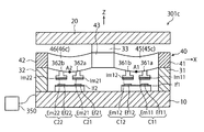
図26は、第3の実施の形態による力覚センサ301cの概略平面図である。また、図27は、図26の[27]−[27]線断面図であり、図28は、図26の[28]−[28]線断面図である。但し、図26では、図面の見やすさのため、受力体20の図示を省略してある。   FIG. 26 is a schematic plan view of the force sensor 301c according to the third embodiment. 27 is a sectional view taken along the line [27]-[27] in FIG. 26, and FIG. 28 is a sectional view taken along the line [28]-[28] in FIG. However, in FIG. 26, the force receiving body 20 is not shown for ease of viewing the drawing.

図26乃至図28に示すように、力覚センサ301cは、湾曲部45c〜48cに各2つの容量素子が設けられている点で、第1及び第2の実施の形態による力覚センサ1c、201cと異なる。具体的には、図26及び図27に示すように、第1湾曲部45cの下面には、第1検出部位A1を挟んで、変形体40の周方向に沿って2つの容量素子C11、C12が配置されている。同様に、第2湾曲部46cの下面には、第2検出部位A2を挟んで、変形体40の周方向に沿って2つの容量素子C21、C22が配置されている。また、図26及び図28に示すように、第3湾曲部47cの下面には、第3検出部位A3を挟んで、変形体40の周方向に沿って2つの容量素子C31、C32が配置されており、第4湾曲部48cの下面には、第4検出部位A4を挟んで、変形体40の周方向に沿って2つの容量素子C41、C42が配置されている。   As shown in FIGS. 26 to 28, the force sensor 301c is provided with two capacitive elements in each of the bending portions 45c to 48c, and thus the force sensor 1c according to the first and second embodiments, Different from 201c. Specifically, as shown in FIGS. 26 and 27, two capacitive elements C11 and C12 are arranged on the lower surface of the first bending portion 45c along the circumferential direction of the deformable body 40 with the first detection portion A1 interposed therebetween. Are arranged. Similarly, on the lower surface of the second curved portion 46c, two capacitive elements C21 and C22 are arranged along the circumferential direction of the deformable body 40 with the second detection portion A2 interposed therebetween. Further, as shown in FIGS. 26 and 28, two capacitive elements C31 and C32 are arranged on the lower surface of the third curved portion 47c along the circumferential direction of the deformable body 40 with the third detection portion A3 interposed therebetween. On the lower surface of the fourth curved portion 48c, two capacitive elements C41 and C42 are arranged along the circumferential direction of the deformable body 40 with the fourth detection portion A4 interposed therebetween.

図示される例において、第1−1容量素子C11、第1−2容量素子C12、第2−1容量素子C21、第2−2容量素子C22、第3−1容量素子C31、第3−2容量素子C32、第4−1容量素子C41及び第4−2容量素子C42は、Z軸正方向から見て(上方から見て)、変形体40の周方向に沿って反時計回り(左回り)にこの順序で配置されている。また、図27及び図28に示すように、各湾曲部45c〜48cに2つずつ配置された容量素子C11〜C42は、対応する検出部位A1〜A4から等間隔で配置されている。   In the illustrated example, the 1-1st capacitive element C11, the 1-2nd capacitive element C12, the 2-1st capacitive element C21, the 2-2nd capacitive element C22, the 3-1st capacitive element C31, the 3-2nd The capacitive element C32, the 4-1st capacitive element C41, and the 4-2nd capacitive element C42 are counterclockwise (counterclockwise) along the circumferential direction of the deformable body 40 when viewed from the Z-axis positive direction (as viewed from above). ) Are arranged in this order. Further, as shown in FIGS. 27 and 28, two capacitive elements C11 to C42 arranged in each of the curved portions 45c to 48c are arranged at equal intervals from the corresponding detection parts A1 to A4.

各容量素子C11〜C42の構成は、第1の実施の形態による力覚センサ1cに採用されている容量素子C1〜C4と、同様である。すなわち、図27に示すように、第1−1容量素子C11は、第1湾曲部45cに支持された第1−1変位電極Em11と、この第1−1変位電極Em11に対向する位置に配置された第1−1固定電極Ef11と、によって構成されている。第1−1変位電極Em11は、第1湾曲部45cに接続された第1−1変形体側支持体361aの下面に、第1−1変位基板Im11を介して支持されている。第1−1固定電極Ef11は、固定体10の上面に固定された第1固定体側支持体371上に、第1固定基板If1を介して支持されている。   The configurations of the respective capacitive elements C11 to C42 are similar to those of the capacitive elements C1 to C4 employed in the force sensor 1c according to the first embodiment. That is, as shown in FIG. 27, the 1-1st capacitive element C11 is disposed at the 1-1st displacement electrode Em11 supported by the first bending portion 45c and at a position facing the 1-1st displacement electrode Em11. And the 1-1st fixed electrode Ef11. The 1-1st displacement electrode Em11 is supported on the lower surface of the 1-1st deformable body side support body 361a connected to the first bending portion 45c via the 1-1st displacement substrate Im11. The 1-1st fixed electrode Ef11 is supported on the first fixed body side support body 371 fixed to the upper surface of the fixed body 10 via the first fixed substrate If1.

また、図27に示すように、第1−2容量素子C12は、第1湾曲部45cに支持された第1−2変位電極Em12と、この第1−2変位電極Em12に対向する位置に配置された第1−2固定電極Ef12と、によって構成されている。第1−2変位電極Em12は、第1湾曲部45cに接続された第1−2変形体側支持体361bの下面に、第1−2変位基板Im12を介して支持されている。第1−2固定電極Ef12は、第1−1固定電極Ef11と同様に、固定体10の上面に固定された第1固定体側支持体371上に、第1固定基板If1を介して支持されている。すなわち、第1固定体側支持体371及び第1固定基板If1は、第1−1容量素子C11及び第1−2容量素子C12に対して共通の構成要素である。   Further, as shown in FIG. 27, the 1-2nd capacitive element C12 is arranged at a position opposite to the 1-2nd displacement electrode Em12 supported by the first bending portion 45c and the 1-2nd displacement electrode Em12. And the 1st-2 fixed electrode Ef12. The first-second displacement electrode Em12 is supported on the lower surface of the first-second deformable body side support body 361b connected to the first curved portion 45c via the first-second displacement substrate Im12. The 1-2 fixed electrode Ef12 is supported on the first fixed body side support body 371 fixed to the upper surface of the fixed body 10 via the first fixed substrate If1 similarly to the 1-1 fixed electrode Ef11. There is. That is, the first fixed body side support body 371 and the first fixed substrate If1 are components common to the 1-1st capacitive element C11 and the 1-2st capacitive element C12.

図27に示すように、第2−1容量素子C21は、第2湾曲部46cに支持された第2−1変位電極Em21と、この第2−1変位電極Em21に対向する位置に配置された第2−1固定電極Ef21と、によって構成されている。第2−1変位電極Em21は、第2湾曲部46cに接続された第2−1変形体側支持体362aの下面に、第2−1変位基板Im21を介して支持されている。第2−1固定電極Ef21は、固定体10の上面に固定された第2固定体側支持体372上に、第2固定基板If2を介して支持されている。   As shown in FIG. 27, the 2-1st capacitive element C21 is arranged at the 2-1st displacement electrode Em21 supported by the second bending portion 46c and at a position facing the 2-1st displacement electrode Em21. The 2-1st fixed electrode Ef21. The 2-1st displacement electrode Em21 is supported on the lower surface of the 2-1st deformable body side support body 362a connected to the second bending portion 46c via the 2-1st displacement substrate Im21. The 2-1st fixed electrode Ef21 is supported on the second fixed body side support body 372 fixed to the upper surface of the fixed body 10 via the second fixed substrate If2.

また、図27に示すように、第2−2容量素子C22は、第2湾曲部46cに支持された第2−2変位電極Em22と、この第2−2変位電極Em22に対向する位置に配置された第2−2固定電極Ef22と、によって構成されている。第2−2変位電極Em22は、第2湾曲部46cに接続された第2−2変形体側支持体362bの下面に、第2−2変位基板Im22を介して支持されている。第2−2固定電極Ef22は、第2−1固定電極Ef21と同様に、固定体10の上面に固定された第2固定体側支持体372上に、第2固定基板If2を介して支持されている。すなわち、第2固定体側支持体372及び第2固定基板If2は、第2−1容量素子C21及び第2−2容量素子C22に対して共通の構成要素である。   Further, as shown in FIG. 27, the 2-2nd capacitive element C22 is arranged at the 2-2nd displacement electrode Em22 supported by the second bending portion 46c and at a position facing the 2-2nd displacement electrode Em22. 2-2 fixed electrode Ef22 that has been formed. The 2-2nd displacement electrode Em22 is supported on the lower surface of the 2-2nd deformation body side support body 362b connected to the second bending portion 46c via the 2-2nd displacement substrate Im22. The 2-2nd fixed electrode Ef22 is supported on the 2nd fixed body side support body 372 fixed to the upper surface of the fixed body 10 via the 2nd fixed substrate If2 similarly to the 2-1 fixed electrode Ef21. There is. That is, the second fixed body side support body 372 and the second fixed substrate If2 are common constituent elements for the 2-1st capacitive element C21 and the 2-2nd capacitive element C22.

図28に示すように、第3−1容量素子C31は、第3湾曲部47cに支持された第3−1変位電極Em31と、この第3−1変位電極Em31に対向する位置に配置された第3−1固定電極Ef31と、によって構成されている。第3−1変位電極Em31は、第3湾曲部47cに接続された第3−1変形体側支持体363aの下面に、第3−1変位基板Im31を介して支持されている。第3−1固定電極Ef31は、固定体10の上面に固定された第3固定体側支持体373上に、第3固定基板If3を介して支持されている。   As shown in FIG. 28, the 3-1st capacitive element C31 is arranged at the 3-1st displacement electrode Em31 supported by the third curved portion 47c and at a position facing the 3-1st displacement electrode Em31. And a 3-1st fixed electrode Ef31. The 3-1st displacement electrode Em31 is supported on the lower surface of the 3-1st deformable body side support body 363a connected to the third bending portion 47c via the 3-1st displacement substrate Im31. The 3-1st fixed electrode Ef31 is supported on the third fixed body side support body 373 fixed to the upper surface of the fixed body 10 through the third fixed substrate If3.

また、図28に示すように、第3−2容量素子C32は、第3湾曲部47cに支持された第3−2変位電極Em32と、この第3−2変位電極Em32に対向する位置に配置された第3−2固定電極Ef32と、によって構成されている。第3−2変位電極Em32は、第3湾曲部47cに接続された第3−2変形体側支持体363bの下面に、第3−2変位基板Im32を介して支持されている。第3−2固定電極Ef32は、第3−1固定電極Ef31と同様に、固定体10の上面に固定された第3固定体側支持体373上に、第3固定基板If3を介して支持されている。すなわち、第3固定体側支持体373及び第3固定基板If3は、第3−1容量素子C31及び第3−2容量素子C32に対して共通の構成要素である。   Further, as shown in FIG. 28, the 3-2nd capacitive element C32 is arranged at a position facing the 3-2nd displacement electrode Em32 supported by the third curved portion 47c and the 3-2nd displacement electrode Em32. 3-2 fixed electrode Ef32. The 3-2nd displacement electrode Em32 is supported on the lower surface of the 3-2nd deformable body side support body 363b connected to the 3rd curved portion 47c via the 3-2nd displacement substrate Im32. The 3-2nd fixed electrode Ef32 is supported on the 3rd fixed body side support body 373 fixed to the upper surface of the fixed body 10 via the 3rd fixed substrate If3 similarly to the 3-1 fixed electrode Ef31. There is. That is, the third fixed body side support body 373 and the third fixed substrate If3 are common constituent elements for the 3-1st capacitive element C31 and the 3-2nd capacitive element C32.

更に、図28に示すように、第4−1容量素子C41は、第4湾曲部48cに支持された第4−1変位電極Em41と、この第4−1変位電極Em41に対向する位置に配置された第4−1固定電極Ef41と、によって構成されている。第4−1変位電極Em41は、第4湾曲部48cに接続された第4−1変形体側支持体364aの下面に、第4−1変位基板Im41を介して支持されている。第4−1固定電極Ef41は、固定体10の上面に固定された第3固定体側支持体373上に、第4固定基板If4を介して支持されている。   Further, as shown in FIG. 28, the 4-1st capacitive element C41 is arranged at a position facing the 4-1st displacement electrode Em41 supported by the fourth bending portion 48c and the 4-1st displacement electrode Em41. The 4-1st fixed electrode Ef41 that has been formed. The 4-1st displacement electrode Em41 is supported on the lower surface of the 4-1st deformable body side support body 364a connected to the fourth bending portion 48c via the 4-1st displacement substrate Im41. The 4-1st fixed electrode Ef41 is supported on the 3rd fixed body side support body 373 fixed to the upper surface of the fixed body 10 via the 4th fixed substrate If4.

また、図28に示すように、第4−2容量素子C42は、第4湾曲部48cに支持された第4−2変位電極Em42と、この第4−2変位電極Em42に対向する位置に配置された第4−2固定電極Ef42と、によって構成されている。第4−2変位電極Em42は、第4湾曲部48cに接続された第4−2変形体側支持体364bの下面に、第4−2変位基板Im42を介して支持されている。第4−2固定電極Ef42は、第4−1固定電極Ef41と同様に、固定体10の上面に固定された第4固定体側支持体374上に、第4固定基板If4を介して支持されている。すなわち、第4固定体側支持体374及び第4固定基板If4は、第4−1容量素子C41及び第4−2容量素子C42に対して共通の構成要素である。その他の構成は第1の実施の形態による力覚センサ1cとほぼ同様であるため、図面において対応する構成要素には同様の符号を付し、その詳細な説明は省略する。   Further, as shown in FIG. 28, the 4-2nd capacitive element C42 is arranged at the 4-2nd displacement electrode Em42 supported by the fourth curved portion 48c and at a position facing the 4-2nd displacement electrode Em42. And the 4-2nd fixed electrode Ef42 that is formed. The 4-2nd displacement electrode Em42 is supported via the 4-2nd displacement substrate Im42 on the lower surface of the 4-2nd deformable body side support body 364b connected to the fourth bending portion 48c. The 4-2nd fixed electrode Ef42 is supported on the 4th fixed body side support body 374 fixed to the upper surface of the fixed body 10 via the 4th fixed substrate If4 similarly to the 4-1 fixed electrode Ef41. There is. That is, the fourth fixed body side support 374 and the fourth fixed substrate If4 are common constituent elements to the 4-1st capacitive element C41 and the 4-2nd capacitive element C42. Since other configurations are almost the same as those of the force sensor 1c according to the first embodiment, corresponding components are denoted by the same reference numerals in the drawings, and detailed description thereof will be omitted.

なお、第1−1〜第2−4容量素子C11〜C24は、各容量素子C11〜C24を構成する変位電極Em11〜Em24及び固定電極Ef11〜Ef24の実効対向面積が全て同一であり、電極間の離間距離も全て等しくなるように構成されている。   In the 1-1 to 2-4 capacitive elements C11 to C24, the displacement electrodes Em11 to Em24 and the fixed electrodes Ef11 to Ef24 forming the capacitive elements C11 to C24 have the same effective facing area, and The separation distances are also equal to each other.

< 3−2. 作用 >
次に、図29は、図26の力覚センサ301cに対して、力ないしモーメントが作用した時に各容量素子C11〜C24に生じる静電容量値の変動を示す図表である。この図表において、「+」は、容量素子の静電容量値が増大することを示しており、「−」は、容量素子の静電容量値が減少することを示している。
<3-2. Action>
Next, FIG. 29 is a chart showing variations in the capacitance value generated in each of the capacitive elements C11 to C24 when a force or moment acts on the force sensor 301c of FIG. In this chart, "+" indicates that the capacitance value of the capacitance element increases, and "-" indicates that the capacitance value of the capacitance element decreases.

本実施の形態による力覚センサ301cに対して、力ないしモーメントが作用すると、各湾曲部45c〜48cには、作用した力ないしモーメントに応じて、図3〜図9で説明したような弾性変形が生じる。この弾性変形より、容量素子C11〜C42の静電容量値は、図29に示すように変動する。すなわち、第1−1容量素子C11及び第1−2容量素子C12は、第1の実施の形態による力覚センサ1cの第1容量素子C1と同様の挙動を示す(図14のC1の列を参照)。また、第2−1容量素子C21及び第2−2容量素子C22は、第1の実施の形態による力覚センサ1cの第2容量素子C2と同様の挙動を示し(図14のC2の列を参照)、第3−1容量素子C31及び第3−2容量素子C32は、第1の実施の形態による力覚センサ1cの第3容量素子C3と同様の挙動を示し(図14のC3の列を参照)、第4−1容量素子C41及び第4−2容量素子C42は、第1の実施の形態による力覚センサ1cの第4容量素子C4と同様の挙動を示す(図14のC4の列を参照)。   When a force or moment acts on the force sensor 301c according to the present embodiment, the bending portions 45c to 48c are elastically deformed as described in FIGS. 3 to 9 according to the acting force or moment. Occurs. Due to this elastic deformation, the capacitance values of the capacitive elements C11 to C42 fluctuate as shown in FIG. That is, the 1-1st capacitive element C11 and the 1-2nd capacitive element C12 exhibit the same behavior as the first capacitive element C1 of the force sensor 1c according to the first embodiment (see the column of C1 in FIG. 14). reference). Further, the 2-1st capacitive element C21 and the 2-2nd capacitive element C22 behave similarly to the second capacitive element C2 of the force sensor 1c according to the first embodiment (see the column C2 in FIG. 14). ), The 3-1st capacitive element C31 and the 3-2nd capacitive element C32 behave similarly to the third capacitive element C3 of the force sensor 1c according to the first embodiment (column C3 in FIG. 14). ), The 4-1st capacitive element C41 and the 4-2nd capacitive element C42 exhibit the same behavior as the fourth capacitive element C4 of the force sensor 1c according to the first embodiment (of C4 in FIG. 14). See column).

図29に示す図表に鑑み、検出回路250は、次の[式2]に基づいて力覚センサ301cに作用したモーメントMx、My、Mz及び力Fzを算出する。本明細書に記載された各式において、C11〜C24の記号は、第1−1〜第2−4容量素子C11〜C24の静電容量値の変動量をそれぞれ示している。また、Mx、My、Mz及びFzの末尾の符号は、[式2]を用いて計測された力ないしモーメントと、後述される[式3]を用いて計測された力ないしモーメントと、を区別するためのものである。
[式2]
Mx1=−C11−C21+C31+C41
My1=C11−C21−C31+C41
Mz1=−C11+C21−C31+C41
Fz1=−(C11+C21+C31+C41)
この[式2]は、各湾曲部45c〜48cに配置されている各2つの容量素子のうち、Z軸正方向から見て(上方から見て)、変形体40の右回りの方向により進んでいる方の容量素子を用いて、作用した力ないしモーメントを計測するための式である。
In consideration of the chart shown in FIG. 29, the detection circuit 250 calculates the moments Mx, My, Mz and the force Fz acting on the force sensor 301c based on the following [Equation 2]. In each formula described in this specification, the symbols C11 to C24 indicate the amounts of variation in the capacitance values of the 1-1 to 2-4 capacitive elements C11 to C24, respectively. Further, the symbols at the end of Mx, My, Mz and Fz distinguish between the force or moment measured using [Equation 2] and the force or moment measured using [Equation 3] described later. It is for doing.
[Formula 2]
Mx1 = -C11-C21 + C31 + C41
My1 = C11-C21-C31 + C41
Mz1 = -C11 + C21-C31 + C41
Fz1 =-(C11 + C21 + C31 + C41)
This [Formula 2] advances in the clockwise direction of the deformable body 40 when viewed from the Z-axis positive direction (as viewed from above) among the two capacitive elements arranged in the respective curved portions 45c to 48c. This is an equation for measuring the acting force or moment by using the capacitive element of the one.

あるいは、力覚センサ301cに作用したモーメントMx、My、Mz及び力Fzは、次の[式3]を用いても、算出される。
[式3]
Mx2=−C12−C22+C32+C42
My2=C12−C22−C32+C42
Mz2=−C12+C22−C32+C42
Fz2=−(C12+C22+C32+C42)
この[式3]は、各湾曲部45c〜48cに配置されている各2つの容量素子のうち、Z軸正方向から見て(上方から見て)、変形体40の左回りの方向により進んでいる方の容量素子を用いて、作用した力ないしモーメントを計測するための式である。
Alternatively, the moments Mx, My, Mz and the force Fz acting on the force sensor 301c can be calculated by using the following [Formula 3].
[Formula 3]
Mx2 = -C12-C22 + C32 + C42
My2 = C12-C22-C32 + C42
Mz2 = -C12 + C22-C32 + C42
Fz2 =-(C12 + C22 + C32 + C42)
This [Formula 3] advances in the counterclockwise direction of the deformable body 40 when viewed from the Z-axis positive direction (viewed from above) among the two capacitive elements arranged in each of the curved portions 45c to 48c. This is an equation for measuring an applied force or moment by using the capacitive element on the other side.

< 3−3. 故障診断 >
本実施の形態による力覚センサ301cは、単一の力覚センサ301cによって、故障診断を行うことが可能である。ここでは、その診断方法について説明する。
<3-3. Fault diagnosis >
The force sensor 301c according to the present embodiment can perform failure diagnosis with the single force sensor 301c. Here, the diagnosis method will be described.

前述したように、力覚センサ301cに配置されている8つの容量素子C11〜C24は、電極間の実効対向面積及び離間距離が同一である。さらに、[式2]に用いられる4つの容量素子C11、C21、C31、C41と、[式3]に用いられる4つの容量素子C12、C22、C32、C42とは、第1〜第4湾曲部45c〜48cに規定された検出部位A1〜A4に対して対称的に配置されている。これらのことから、正常に機能している力覚センサ301cでは、[式2]に基づいて計測された力ないしモーメントと[式3]に基づいて計測された力ないしモーメントとが、一致することになる。すなわち、正常に機能している力覚センサ301cでは、以下の[式4]の関係が成立する。
[式4]
Mx1=Mx2
My1=My2
Mz1=Mz2
Fz1=Fz2
As described above, the eight capacitive elements C11 to C24 arranged in the force sensor 301c have the same effective facing area between electrodes and the same distance. Furthermore, the four capacitive elements C11, C21, C31, C41 used in [Equation 2] and the four capacitive elements C12, C22, C32, C42 used in [Equation 3] are the first to fourth curved portions. They are arranged symmetrically with respect to the detection parts A1 to A4 defined by 45c to 48c. From these facts, in the force sensor 301c that is functioning normally, the force or moment measured based on [Equation 2] and the force or moment measured based on [Equation 3] match. become. That is, in the force sensor 301c that is functioning normally, the following [Equation 4] relationship holds.
[Formula 4]
Mx1 = Mx2
My1 = My2
Mz1 = Mz2
Fz1 = Fz2

このことから、次のようにして力覚センサ301cの故障診断を行うことができる。すなわち、検出回路250は、力覚センサ301cに作用した力ないしモーメントを[式2]及び[式3]の両方に基づいて計測し、[式2]に基づいて計測された値(Mx1、My1、Mz1、Fz1)と、[式3]に基づいて計測された値(Mx2、My2、Mz2、Fz2)と、の差の絶対値が、全て、所定の閾値([式5]におけるCmx、Cmy、Cmz、Cfz)以下であれば、当該力覚センサ301cが正常に機能していると判定する。すなわち、次の[式5]が成立しているとき、検出回路250は、力覚センサ301cが正常に機能していると判定する。なお、本実施の形態では、所定の閾値Cmx、Cmy、Cmz、Cfzは、予め検出回路250内に格納されている。
[式5]
|Mx1−Mx2|≦Cmx 且つ
|My1−My2|≦Cmy 且つ
|Mz1−Mz2|≦Cmz 且つ
|Fz1−Fz2|≦Cfz
From this, the failure diagnosis of the force sensor 301c can be performed as follows. That is, the detection circuit 250 measures the force or moment acting on the force sensor 301c based on both [Equation 2] and [Equation 3], and the values (Mx1, My1) measured based on [Equation 2]. , Mz1, Fz1) and the absolute values of the differences between the values (Mx2, My2, Mz2, Fz2) measured based on [Equation 3] are all predetermined thresholds (Cmx, Cmy in [Equation 5]). , Cmz, Cfz) or less, it is determined that the force sensor 301c is functioning normally. That is, when the following [Equation 5] is established, the detection circuit 250 determines that the force sensor 301c is functioning normally. In the present embodiment, the predetermined threshold values Cmx, Cmy, Cmz, and Cfz are stored in the detection circuit 250 in advance.
[Formula 5]
| Mx1-Mx2 | ≦ Cmx and | My1-My2 | ≦ Cmy and | Mz1-Mz2 | ≦ Cmz and | Fz1-Fz2 | ≦ Cfz

その一方、前記差のうち少なくとも1つが、所定の閾値C1よりも大きければ、検出回路250は、力覚センサ301cが正常に機能していない(故障している)と判定する。すなわち、次の[式6]が成立しているとき、検出回路250は、力覚センサ301cが正常に機能していないと判定する。
[式6]
|Mx1−Mx2|>Cmx または
|My1−My2|>Cmy または
|Mz1−Mz2|>Cmz または
|Fz1−Fz2|>Cfz
On the other hand, if at least one of the differences is larger than the predetermined threshold value C1, the detection circuit 250 determines that the force sensor 301c is not functioning normally (has failed). That is, when the following [Equation 6] is established, the detection circuit 250 determines that the force sensor 301c is not functioning normally.
[Formula 6]
| Mx1-Mx2 |> Cmx or | My1-My2 |> Cmy or | Mz1-Mz2 |> Cmz or | Fz1-Fz2 |> Cfz

以上のような本実施の形態による力覚センサ301cによれば、第1〜第4湾曲部45c〜48cに2つずつ配置された容量素子のうち、各1つ(合計4つ)を用いて計測された力ないしモーメントの値と、残りの各1つ(合計4つ)を用いて計測された力ないしモーメントの値と、の差に基づいて、単一の力覚センサ301cによってその故障を診断することができる。このことにより、力覚センサ301cの安全性及び信頼性が向上される。   According to the force sensor 301c of the present embodiment as described above, one each (four in total) of the two capacitive elements arranged in each of the first to fourth bending portions 45c to 48c is used. The failure is detected by the single force sensor 301c based on the difference between the measured force or moment value and the remaining force or moment value (four in total). Can be diagnosed. This improves the safety and reliability of the force sensor 301c.

以上の説明では、力覚センサ301cの故障診断を行うために、[式2]に基づいて求められた特定の力ないしモーメントと[式3]に基づいて求められた当該特定の力ないしモーメントとを比較していたが、このような方法には限定されない。例えば、[式2]と「式3」との和に基づいて求められた特定の力ないしモーメント(例:Mx1+Mx2)と、[式2]または「式3」のいずれか一方に基づいて求められた当該特定の力ないしモーメント(例:Mx1またはMx2)とを比較することによって、故障診断を行っても良い。具体的な診断の方法は、上述した方法と同様である。すなわち、X軸まわりのモーメントMxに着目して故障診断を行う場合、[式2]と「式3」との和であるMx1+Mx2に基づいて求められた特定の力ないしモーメントをM12とすると、|Mx12−Mx1|または|Mx12−Mx2|が所定の閾値を超えているか否かが評価される。このことは、他の力ないしモーメントに基づいて故障診断を行う場合にも当てはまる。   In the above description, in order to perform the failure diagnosis of the force sensor 301c, the specific force or moment obtained based on [Equation 2] and the specific force or moment obtained based on [Equation 3] are used. However, the method is not limited to such a method. For example, a specific force or moment (eg Mx1 + Mx2) obtained based on the sum of [Equation 2] and "Equation 3" and either one of [Equation 2] or "Equation 3" The failure diagnosis may be performed by comparing the specific force or moment (eg, Mx1 or Mx2). The specific diagnosis method is the same as the method described above. That is, in the case of performing a failure diagnosis focusing on the moment Mx about the X axis, if M12 is a specific force or moment obtained based on Mx1 + Mx2, which is the sum of [Equation 2] and [Equation 3], then | It is evaluated whether or not Mx12-Mx1 | or | Mx12-Mx2 | exceeds a predetermined threshold value. This also applies to fault diagnosis based on other forces or moments.

更に、以上の説明では、力ないしモーメントを測定するために、[式2]及び「式3」のうちの一方の式を用いたが、[式2]と「式3」との和(例:Mx1+Mx2)を用いても良い。   Further, in the above description, one of [Equation 2] and “Equation 3” is used to measure the force or moment, but the sum of [Equation 2] and “Equation 3” (example : Mx1 + Mx2) may be used.

<<< §4. 本発明の第4の実施の形態による力覚センサ >>>
< 4−1. 構成 >
次に、本発明の第4の実施の形態による力覚センサ401cについて説明する。
<<<< §4. Force Sensor According to Fourth Embodiment of the Present Invention >>
<4-1. Composition>
Next, a force sensor 401c according to a fourth embodiment of the present invention will be described.

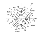
図30は、本発明の第4の実施の形態による力覚センサ401cの概略平面図であり、図31は、図30の[31]−[31]線断面図であり、図32は、図30の[32]−[32]線断面図である。但し、図30では、図面の見やすさのため、受力体20の図示を省略してある。   30 is a schematic plan view of the force sensor 401c according to the fourth embodiment of the present invention, FIG. 31 is a sectional view taken along the line [31]-[31] of FIG. 30, and FIG. It is the [32]-[32] sectional view taken on the line of 30. However, in FIG. 30, the force receiving body 20 is not shown for ease of viewing the drawing.

図30乃至図32に示すように、本実施の形態による力覚センサ401cは、第1〜第4湾曲部445c〜448cが互いに異なる2つのバネ定数を有する部分から構成されている点で、第3の実施の形態による力覚センサ301cと異なる。具体的には、図30及び図31に示すように、第1湾曲部445cは、正のX軸と正のV軸とで挟まれた領域に位置する、相対的にバネ定数が小さい第1低弾力部445Lと、正のV軸と正のY軸とで挟まれた領域に位置する、相対的にバネ定数が大きい第1高弾力部445Hと、によって構成されている。第1低弾力部445Lと第1高弾力部445Hとは、第1検出部位A1において(V軸上において)一体的に接続されている。同様に、第2湾曲部446cは、正のY軸と正のW軸とで挟まれた領域に位置する、相対的にバネ定数が小さい第2低弾力部446Lと、正のW軸と負のX軸とで挟まれた領域に位置する、相対的にバネ定数が大きい第2高弾力部446Hと、によって構成されている。第2低弾力部446Lと第2高弾力部446Hとは、第2検出部位A2において(W軸上において)一体的に接続されている。   As shown in FIGS. 30 to 32, the force sensor 401c according to the present embodiment is characterized in that the first to fourth bending portions 445c to 448c are composed of portions having two spring constants different from each other. It is different from the force sensor 301c according to the third embodiment. Specifically, as shown in FIGS. 30 and 31, the first bending portion 445c is located in a region sandwiched by the positive X axis and the positive V axis and has a relatively small spring constant. It is composed of a low elastic portion 445L and a first high elastic portion 445H having a relatively large spring constant, which is located in a region sandwiched by the positive V axis and the positive Y axis. The first low-elasticity portion 445L and the first high-elasticity portion 445H are integrally connected at the first detection portion A1 (on the V axis). Similarly, the second bending portion 446c is located in a region sandwiched by the positive Y axis and the positive W axis, and has a second low elastic portion 446L having a relatively small spring constant and the positive W axis and the negative W axis. And a second high-elasticity portion 446H having a relatively large spring constant, which is located in a region sandwiched by the X axis. The second low-elasticity portion 446L and the second high-elasticity portion 446H are integrally connected at the second detection portion A2 (on the W axis).

また、図30及び図32に示すように、第3湾曲部447cは、負のX軸と負のV軸とで挟まれた領域に位置する、相対的にバネ定数が小さい第3低弾力部447Lと、負のV軸と負のY軸とで挟まれた領域に位置する、相対的にバネ定数が大きい第3高弾力部447Hと、によって構成されている。第3低弾力部447Lと第3高弾力部447Hとは、第3検出部位A3において(V軸上において)一体的に接続されている。同様に、第4湾曲部448cは、負のY軸と負のW軸とで挟まれた領域に位置する、相対的にバネ定数が小さい第4低弾力部448Lと、負のW軸と正のX軸とで挟まれた領域に位置する、相対的にバネ定数が大きい第4高弾力部448Hと、によって構成されている。第4低弾力部448Lと第4高弾力部448Hとは、第4検出部位A4において(W軸上において)一体的に接続されている。   Further, as shown in FIGS. 30 and 32, the third bending portion 447c is located in a region sandwiched by the negative X axis and the negative V axis, and has a relatively low spring constant. 447L and a third high-elasticity portion 447H having a relatively large spring constant, which is located in a region sandwiched by the negative V axis and the negative Y axis. The third low-elasticity portion 447L and the third high-elasticity portion 447H are integrally connected at the third detection portion A3 (on the V axis). Similarly, the fourth bending portion 448c is located in a region sandwiched by the negative Y axis and the negative W axis, and has a fourth low elastic portion 448L having a relatively small spring constant, and the negative W axis and the positive W axis. And a fourth high elastic portion 448H having a relatively large spring constant, which is located in a region sandwiched by the X axis. The fourth low-elasticity portion 448L and the fourth high-elasticity portion 448H are integrally connected at the fourth detection portion A4 (on the W axis).

図31及び図32に示すように、各低弾力部445L〜448Lは、各高弾力部445H〜448Hと比較して、Z軸方向(上下方向)の厚みが小さく構成されている。もちろん、このような態様には限定されず、他の実施の形態では、各低弾力部445L〜448Lが各高弾力部445H〜448Hと比較して、径方向の幅が小さく構成されることによりバネ定数が相違していても良いし、互いに異なる材質で構成されることによりバネ定数が相違していても良い。   As shown in FIGS. 31 and 32, the low-elasticity portions 445L to 448L are configured to have a smaller thickness in the Z-axis direction (vertical direction) than the high-elasticity portions 445H to 448H. Of course, the present invention is not limited to such an aspect, and in other embodiments, the low-elasticity portions 445L to 448L have a smaller radial width than the high-elasticity portions 445H to 448H. The spring constants may be different, or the spring constants may be different by being made of different materials.

図30乃至図32に示すように、各湾曲部445c〜448cには、第3の実施の形態による力覚センサ301cと同様に、各2つの容量素子C11〜C42が配置されている。当該各2つの容量素子は、対応する検出部位A1〜A4を挟んで、変形体40の周方向に沿って配置されている。具体的には、第1−1容量素子C11は、第1低弾力部445Lの下面に配置されており、第1−2容量素子C12は、第1高弾力部445Hの下面に配置されている。第2−1容量素子C21は、第2低弾力部446Lの下面に配置されており、第2−2容量素子C22は、第2高弾力部446Hの下面に配置されている。第3−1容量素子C31は、第3低弾力部447Lの下面に配置されており、第3−2容量素子C32は、第3高弾力部447Hの下面に配置されている。第4−1容量素子C41は、第4低弾力部448Lの下面に配置されており、第4−2容量素子C42は、第4高弾力部448Hの下面に配置されている。その他の構成は第3の実施の形態と同様であるため、図面において対応する構成要素には同様の符号を付し、その詳細な説明は省略する。   As shown in FIGS. 30 to 32, each of the two curved elements 445c to 448c is provided with two capacitive elements C11 to C42 similarly to the force sensor 301c according to the third embodiment. The two capacitive elements are arranged along the circumferential direction of the deformable body 40 with the corresponding detection parts A1 to A4 sandwiched therebetween. Specifically, the 1-1st capacitive element C11 is arranged on the lower surface of the first low elastic portion 445L, and the 1-2nd capacitive element C12 is arranged on the lower surface of the first high elastic portion 445H. . The 2-1st capacitive element C21 is arranged on the lower surface of the second low-elasticity portion 446L, and the 2-2nd capacitive element C22 is arranged on the lower surface of the second high-elasticity portion 446H. The 3-1st capacitive element C31 is arranged on the lower surface of the third low-elasticity portion 447L, and the 3-2nd capacitive element C32 is arranged on the lower surface of the third high-elasticity portion 447H. The 4-1st capacitive element C41 is arranged on the lower surface of the fourth low-elasticity portion 448L, and the 4-2nd capacitive element C42 is arranged on the lower surface of the fourth high-elasticity portion 448H. Since other configurations are similar to those of the third embodiment, corresponding components in the drawings are designated by the same reference numerals, and detailed description thereof will be omitted.

< 4−2. 作用 >
次に、図33は、図30の力覚センサ401cに対して、力ないしモーメントが作用した時に各容量素子C11〜C24に生じる静電容量値の変動を示す図表である。この図表において、「+」は、静電容量値が増大することを示しており、「++」は、静電容量値が大きく増大することを示している。また、「−」は、静電容量値が減少することを示しており、「−−」は、静電容量値が大きく減少することを示している。
<4-2. Action>
Next, FIG. 33 is a chart showing variations in the capacitance value generated in each of the capacitive elements C11 to C24 when a force or moment acts on the force sensor 401c of FIG. In this chart, “+” indicates that the capacitance value increases, and “++” indicates that the capacitance value greatly increases. Further, “−” indicates that the electrostatic capacitance value decreases, and “−−” indicates that the electrostatic capacitance value greatly decreases.

本実施の形態による力覚センサ401cに対して、力ないしモーメントが作用すると、各湾曲部445c〜448cには、全体として、作用した力ないしモーメントに応じて、図3〜図9で説明したような弾性変形が生じる。したがって、この弾性変形により、容量素子C11〜C42の静電容量値が変動する。この変動は、第3の実施の形態による力覚センサ301cの各容量素子C11〜C42の静電容量値とほぼ同様である。但し、バネ定数の相違から、各湾曲部445c〜448cでは、低弾力部444L〜448Lにおいて相対的に大きな弾性変形が生じ、高弾力部444H〜448Hにおいて相対的に小さな弾性変形が生じる。このため、図33に示すように、低弾力部444L〜448Lに配置された容量素子C11、C21、C31、C41において相対的に大きな静電容量値の変動が生じ、高弾力部444H〜448Hに配置された容量素子C12、C22、C32、C42において相対的に小さな静電容量値の変動が生じる。   When a force or moment acts on the force sensor 401c according to the present embodiment, the bending portions 445c to 448c as a whole are described with reference to FIGS. 3 to 9 according to the acting force or moment. Elastic deformation occurs. Therefore, due to this elastic deformation, the capacitance values of the capacitive elements C11 to C42 vary. This variation is almost the same as the capacitance value of each of the capacitive elements C11 to C42 of the force sensor 301c according to the third embodiment. However, due to the difference in spring constant, in the curved portions 445c to 448c, relatively large elastic deformation occurs in the low elastic portions 444L to 448L, and relatively small elastic deformation occurs in the high elastic portions 444H to 448H. Therefore, as shown in FIG. 33, a relatively large capacitance value variation occurs in the capacitive elements C11, C21, C31, C41 arranged in the low elastic portions 444L to 448L, and the high elastic portions 444H to 448H. A relatively small capacitance value variation occurs in the arranged capacitance elements C12, C22, C32, C42.

力覚センサ401cに作用したモーメントMx、My、Mz及び力Fzは、図33に示す図表に基づき、次の[式7]を用いて算出される。Mx、My、Mz及びFzの末尾の符号は、[式7]を用いて算出される力ないしモーメントと、後述される[式8]を用いて算出される力ないしモーメントと、を区別するためのものである。
[式7]
Mx1=−C11−C21+C31+C41
My1=C11−C21−C31+C41
Mz1=−C11+C21−C31+C41
Fz1=−(C11+C21+C31+C41)
この[式7]は、第1〜第4湾曲部445c〜448cに配置されている各2つの容量素子のうち、低弾力部445L〜448Lに配置されている方の4つの容量素子C11、C21、C31、C41を用いて、作用した力ないしモーメントを計測するための式である。
The moments Mx, My, Mz and the force Fz acting on the force sensor 401c are calculated using the following [Equation 7] based on the chart shown in FIG. The symbols at the end of Mx, My, Mz, and Fz are for distinguishing the force or moment calculated using [Equation 7] from the force or moment calculated using [Equation 8] described below. belongs to.
[Formula 7]
Mx1 = -C11-C21 + C31 + C41
My1 = C11-C21-C31 + C41
Mz1 = -C11 + C21-C31 + C41
Fz1 =-(C11 + C21 + C31 + C41)
This [Equation 7] is based on the four capacitive elements C11 and C21 that are arranged in the low-elasticity portions 445L to 448L among the two capacitive elements arranged in the first to fourth curved portions 445c to 448c. , C31, C41 are used to measure the acting force or moment.

あるいは、力覚センサ401cに作用したモーメントMx、My、Mz及び力Fzは、次の[式8]を用いても算出される。
[式8]
Mx2=−C12−C22+C32+C42
My2=C12−C22−C32+C42
Mz2=−C12+C22−C32+C42
Fz2=−(C12+C22+C32+C42)
この[式8]は、第1〜第4湾曲部445c〜448cに配置されている各2つの容量素子のうち、高弾力部445H〜448Hに配置されている方の4つの容量素子C12、C22、C32、C42を用いて、作用した力ないしモーメントを計測するための式である。
Alternatively, the moments Mx, My, Mz and the force Fz acting on the force sensor 401c are also calculated using the following [Formula 8].
[Formula 8]
Mx2 = -C12-C22 + C32 + C42
My2 = C12-C22-C32 + C42
Mz2 = -C12 + C22-C32 + C42
Fz2 =-(C12 + C22 + C32 + C42)
This [Formula 8] is based on the four capacitive elements C12 and C22 of the two capacitive elements disposed in the first to fourth curved portions 445c to 448c, which are disposed in the high elastic portions 445H to 448H. , C32, C42 are used to measure the acting force or moment.

本実施の形態では、図33に示す図表に鑑み、検出回路450は、低弾力部445L〜448Lに配置されている4つの容量素子C11、C21、C31、C41の静電容量値の変動に基づく[式7]を用いて作用した力ないしモーメントを計測する。このことにより、S/Nに優れた高感度の計測が可能となる。もちろん、[式8]を用いて作用した力ないしモーメントを計測しても良い。   In the present embodiment, in view of the chart shown in FIG. 33, the detection circuit 450 is based on the variation of the capacitance values of the four capacitive elements C11, C21, C31, C41 arranged in the low-elasticity portions 445L to 448L. The force or moment acting is measured using [Equation 7]. This enables highly sensitive measurement with excellent S / N. Of course, the force or moment acting may be measured using [Equation 8].

< 4−3. 故障診断 >
本実施の形態による力覚センサ401cは、次の点で、第3の実施の形態による力覚センサ301cよりも高度な故障診断を行うことができる。すなわち、第3の実施の形態による力覚センサ301cは、電極が破損したときや、電極間に異物が混入したときには、故障を検知することが可能である。その一方、変形体40に金属疲労が生じることによって当該力覚センサ301cが正常に機能しなくなった場合には、[式2]に基づいて計測された力ないしモーメント(Mx1、My1、Mz1、Fz1)と[式3]に基づいて計測された力ないしモーメント(Mx2、My2、Mz2、Fz2)との間に、相違が生じない可能性がある。この場合、力覚センサ301cは、故障診断を適正に行うことができない。変形体40に金属疲労が生じると、変形体40を構成する弾性体にクラック等が生じ、最終的には変形体40が破断してしまう恐れがある。このため、金属疲労による故障をも検知することが可能な力覚センサを提供できれば、信頼性及び安全性を一層高めることができる。
<4-3. Fault diagnosis >
The force sensor 401c according to the present embodiment can perform a higher failure diagnosis than the force sensor 301c according to the third embodiment in the following points. That is, the force sensor 301c according to the third embodiment can detect a failure when the electrodes are damaged or when a foreign substance is mixed between the electrodes. On the other hand, when the force sensor 301c does not function normally due to metal fatigue of the deformable body 40, the force or moment (Mx1, My1, Mz1, Fz1) measured based on [Equation 2] is obtained. ) And the force or moment (Mx2, My2, Mz2, Fz2) measured based on [Equation 3] may not be different. In this case, the force sensor 301c cannot properly perform the failure diagnosis. When metal fatigue occurs in the deformable body 40, the elastic body forming the deformable body 40 is cracked and the deformable body 40 may eventually break. Therefore, if a force sensor capable of detecting a failure due to metal fatigue can be provided, reliability and safety can be further enhanced.

本実施の形態による力覚センサ401cは、このような問題に対処するためのものである。すなわち、力覚センサ401cは、変形体40に金属疲労が生じることによって正常に機能しなくなった場合にも、適正に故障診断を行うことができるのである。以下、本実施の形態による力覚センサ401cによる故障診断について、詳細に説明する。   The force sensor 401c according to the present embodiment is for coping with such a problem. That is, the force sensor 401c can properly perform the failure diagnosis even when the deformable body 40 fails to function normally due to metal fatigue. Hereinafter, the failure diagnosis by the force sensor 401c according to the present embodiment will be described in detail.

まず、故障診断の原理について説明する。力覚センサ401cの変形体40に繰り返しの負荷が作用すると、当該変形体40には、金属疲労が生じる。この金属疲労が蓄積されると、変形体40の強度が低下し、最終的には変形体40が破断することになる。一般的に、金属材料に金属疲労が蓄積すると、当該金属材料が軟化する。このため、第1〜第4湾曲部445c〜448cのバネ定数が、低下する。換言すれば、変形体40は、金属疲労の蓄積によって、初期状態と比較して、作用する力ないしモーメントに対する感度が上昇する。   First, the principle of failure diagnosis will be described. When a repeated load acts on the deformable body 40 of the force sensor 401c, metal fatigue occurs in the deformable body 40. When this metal fatigue is accumulated, the strength of the deformable body 40 is reduced, and the deformable body 40 is eventually broken. Generally, when metal fatigue accumulates in a metal material, the metal material softens. Therefore, the spring constants of the first to fourth bending portions 445c to 448c decrease. In other words, the deformable body 40 has increased sensitivity to the acting force or moment as compared with the initial state due to the accumulation of metal fatigue.

図34は、図30に示す力覚センサ401cに金属疲労が生じていない状態(初期状態)において、当該力覚センサ401cに作用するX軸まわりのモーメントMxの大きさと、当該力覚センサ401cから出力される、モーメントMxを示す電気信号と、の関係を示すグラフであり、図35は、図30の力覚センサ401cに金属疲労が生じている状態において、力覚センサ401cに作用するX軸まわりのモーメントMxの大きさと、当該力覚センサ401cから出力される、モーメントMxを示す電気信号と、の関係を示すグラフである。図34及び図35の符号「T1」は、低弾力部445L〜448Lに配置された4つの容量素子の静電容量値の変動量に基づく電気信号である第1電気信号を示しており、符号「T2」は、高弾力部445H〜448Hに配置された4つの容量素子の静電容量値の変動量に基づく電気信号である第2電気信号を示している。また、「T1」及び「T2」の末尾の符号は、初期状態における電気信号(末尾にaを付加)と、金属疲労が蓄積している状態における電気信号(末尾にbを付加)と、を区別するためのものである。   FIG. 34 shows the magnitude of the moment Mx about the X axis acting on the force sensor 401c and the force sensor 401c when the force sensor 401c shown in FIG. 30 has no metal fatigue (initial state). 35 is a graph showing a relationship between the output electric signal and the electric signal indicating the moment Mx, and FIG. 35 is an X-axis acting on the force sensor 401c in a state where metal fatigue occurs in the force sensor 401c of FIG. 6 is a graph showing the relationship between the magnitude of the surrounding moment Mx and the electrical signal indicating the moment Mx output from the force sensor 401c. Reference numeral “T1” in FIGS. 34 and 35 indicates the first electric signal that is an electric signal based on the amount of change in the capacitance value of the four capacitive elements arranged in the low-elasticity portions 445L to 448L. “T2” indicates a second electric signal that is an electric signal based on the amount of change in the capacitance value of the four capacitive elements arranged in the high-elasticity portions 445H to 448H. The symbols at the end of "T1" and "T2" indicate the electric signal in the initial state (adding a to the end) and the electric signal in the state where metal fatigue is accumulated (adding b to the end). It is for distinguishing.

第1電気信号T1及び第2電気信号T2を具体的に書き下すと、次の[式9]のようになる。
[式7]
T1(T1a、T1b)=−C11−C21+C31+C41
T2(T2a、T2b)=−C12−C22+C32+C42
When the first electric signal T1 and the second electric signal T2 are specifically written, the following [Equation 9] is obtained.
[Formula 7]
T1 (T1a, T1b) = − C11−C21 + C31 + C41
T2 (T2a, T2b) =-C12-C22 + C32 + C42

図34を参照すると、初期状態の第1電気信号T1aを示すグラフ(直線)の傾き(感度)は、2.0であり、初期状態の第2電気信号T2aを示すグラフ(直線)の傾き(感度)は、0.5である。その一方、図35を参照すると、金属疲労が蓄積している状態の第1電気信号T1bを示すグラフ(直線)の傾き(感度)は、3.0であり、金属疲労が蓄積している状態の第2電気信号T2bを示すグラフ(直線)の傾き(感度)は、0.6である。   Referring to FIG. 34, the slope (sensitivity) of the graph (straight line) showing the first electric signal T1a in the initial state is 2.0, and the slope (sensitivity) of the graph (straight line) showing the second electric signal T2a in the initial state ( The sensitivity) is 0.5. On the other hand, referring to FIG. 35, the slope (sensitivity) of the graph (straight line) showing the first electrical signal T1b in the state where metal fatigue is accumulated is 3.0, and the state where metal fatigue is accumulated The slope (sensitivity) of the graph (straight line) showing the second electric signal T2b of is 0.6.

これらのことから、力覚センサ401cは、変形体への金属疲労の蓄積によって、作用するX軸まわりのモーメントMxに対する感度が上昇していることが分かる。とりわけ、低弾力部445L〜448Lに配置された4つの容量素子の検出感度が50%も上昇している。その一方、高弾力部445H〜448Hに配置された4つの容量素子の検出感度も上昇してはいるが、その割合は20%にとどまっている。   From these, it can be seen that the force sensor 401c has increased sensitivity to the acting moment Mx about the X axis due to the accumulation of metal fatigue in the deformable body. Particularly, the detection sensitivities of the four capacitive elements arranged in the low-elasticity portions 445L to 448L are increased by 50%. On the other hand, although the detection sensitivities of the four capacitive elements arranged in the high-elasticity portions 445H to 448H have also increased, the ratio remains at 20%.

ここで着目すべきは、低弾力部445L〜448Lに配置された4つの容量素子C11、C21、C31、C41と高弾力部445H〜448Hに配置された4つの容量素子C12、C22、C32、C42とで、感度の変化が異なっているということである。このような差異は、高弾力部445H〜448Hに生じる歪よりも低弾力部445L〜448Lに生じる歪の方が大きいため、相対的に低弾力部445L〜448Lに金属疲労が多く蓄積することに起因している。このような感度の変化を第1電気信号T1と第2電気信号T2との比率に着目して定量的に評価すると、次のとおりである。すなわち、初期状態では、第1電気信号T1aと第2電気信号T2aとの比率(T1a/T2a)は、4.0であったが、金属疲労が蓄積すると、第1電気信号T1bと第2電気信号T2bとの比率(T1b/T2b)は、5.0に上昇した。   It should be noted here that four capacitive elements C11, C21, C31, C41 arranged in the low elastic portions 445L to 448L and four capacitive elements C12, C22, C32, C42 arranged in the high elastic portions 445H to 448H. That is, the change in sensitivity is different. The difference is that the strain generated in the low-elasticity portions 445L to 448L is larger than the strain generated in the high-elasticity portions 445H to 448H, so that a large amount of metal fatigue accumulates in the low-elasticity portions 445L to 448L. It is due. The change in sensitivity as described above is quantitatively evaluated by focusing on the ratio between the first electric signal T1 and the second electric signal T2. That is, in the initial state, the ratio (T1a / T2a) of the first electric signal T1a and the second electric signal T2a was 4.0, but when metal fatigue accumulates, the first electric signal T1b and the second electric signal The ratio with the signal T2b (T1b / T2b) increased to 5.0.

金属疲労が発現するメカニズムを踏まえれば、この比率T1/T2は、繰り返しの負荷(力ないしモーメント)が作用することに伴って4.0から5.0まで次第に上昇する。本実施の形態による力覚センサ401cは、作用した力ないしモーメントの計測に加え、前記比率T1/T2の変化に着目することによって、力覚センサ1cの故障診断をも行う。故障診断は、検出回路450が、計測時点における第1電気信号T1と第2電気信号T2との比率(T1/T2)と、初期状態における第1電気信号T1aと第2電気信号T2aとの比率(T1a/T2a)と、の差((T1/T2)−(T1a/T2a))が所定の値(閾値C)を超えているか否かを評価することによって、行われる。すなわち、以下の[式10]が成立しているとき、検出回路450は、力覚センサ401cが正常に機能していると判定する。なお、本実施の形態では、初期状態における第1電気信号T1aと第2電気信号T2aとの比率(T1a/T2a)及び閾値Cは、予め検出回路450内に記憶されている。
[式10]
(T1/T2)−(T1a/T2a)≦C (C:閾値)
Considering the mechanism of metal fatigue, this ratio T1 / T2 gradually increases from 4.0 to 5.0 with the repeated load (force or moment). The force sensor 401c according to the present embodiment also performs a failure diagnosis of the force sensor 1c by paying attention to the change in the ratio T1 / T2 in addition to measuring the applied force or moment. In the failure diagnosis, the detection circuit 450 uses the ratio (T1 / T2) of the first electric signal T1 and the second electric signal T2 at the time of measurement and the ratio of the first electric signal T1a and the second electric signal T2a in the initial state. It is performed by evaluating whether or not the difference between (T1a / T2a) and ((T1 / T2)-(T1a / T2a)) exceeds a predetermined value (threshold value C). That is, when the following [Formula 10] is established, the detection circuit 450 determines that the force sensor 401c is functioning normally. In the present embodiment, the ratio (T1a / T2a) between the first electric signal T1a and the second electric signal T2a and the threshold value C in the initial state are stored in the detection circuit 450 in advance.
[Formula 10]
(T1 / T2)-(T1a / T2a) ≦ C (C: threshold)

一方、以下の[式11]が成立しているとき、検出回路450は、力覚センサ401cが正常に機能していない(故障している)と判定する。
[式11]
(T1/T2)−(T1a/T2a)>C (C:閾値)
On the other hand, when the following [Equation 11] is established, the detection circuit 450 determines that the force sensor 401c is not functioning normally (has a failure).
[Formula 11]
(T1 / T2)-(T1a / T2a)> C (C: threshold)

以上の説明においては、力覚センサ401cに対してX軸まわりのモーメントMxが作用した場合を例に説明を行ったが、その他のモーメントMy、Mzないし力Fzが作用した場合も、同様にして故障診断を行うことができる。具体的には、着目する力ないしモーメントについて、[式7]に記載された式を第1電気信号T1とし、且つ、[式8]に記載された式を第2電気信号T2とする。このとき、力覚センサ401cに作用する力ないしモーメントと第1及び第2電気信号T1、T2との関係は、初期状態では図34に示すグラフと同様であり、変形体40に金属疲労が蓄積している状態では図35に示すグラフと同様である。但し、Z軸方向の力Fzが作用した場合には、横軸の「モーメント」を「力」と読み替えることとする。したがって、いずれの力ないしモーメントが作用した場合であっても、前述した[式10]及び[式11]に基づいて適正に力覚センサ401cの故障診断が行われる。   In the above description, the case where the moment Mx about the X-axis acts on the force sensor 401c has been described as an example, but the same applies when the other moments My, Mz or the force Fz act. Fault diagnosis can be performed. Specifically, regarding the force or moment of interest, the formula described in [Formula 7] is the first electric signal T1, and the formula described in [Formula 8] is the second electric signal T2. At this time, the relationship between the force or moment acting on the force sensor 401c and the first and second electric signals T1 and T2 is similar to the graph shown in FIG. 34 in the initial state, and metal fatigue is accumulated in the deformable body 40. In the state where it is doing, it is similar to the graph shown in FIG. However, when the force Fz in the Z-axis direction acts, the “moment” on the horizontal axis is read as “force”. Therefore, no matter what force or moment acts, the failure diagnosis of the force sensor 401c is appropriately performed based on the above [Equation 10] and [Equation 11].

以上のような本実施の形態によれば、力ないしモーメントを計測しつつ、変形体40に発現した金属疲労による故障をも検知可能な力覚センサ401cを提供することができる。これにより、力覚センサ401cの信頼性及び安全性が一層高められる。   According to the present embodiment as described above, it is possible to provide the force sensor 401c capable of detecting a failure due to metal fatigue that has occurred in the deformable body 40 while measuring a force or a moment. This further enhances the reliability and safety of the force sensor 401c.

<<< §5. 本発明の第5の実施の形態による力覚センサ >>>
次に、本発明の第5の実施の形態による力覚センサ501cについて説明する。
<<<< §5. Force sensor according to a fifth embodiment of the present invention >>>
Next, a force sensor 501c according to a fifth embodiment of the present invention will be described.

図36は、本発明の第5の実施の形態による力覚センサ501cの基本構造501を示す概略平面図であり、図37は、図36の[37]−[37]線断面図である。   36 is a schematic plan view showing a basic structure 501 of a force sensor 501c according to a fifth embodiment of the present invention, and FIG. 37 is a sectional view taken along line [37]-[37] of FIG.

図36及び37に示すように、基本構造501は、固定体510及び受力体520の構造が第1の実施の形態による力覚センサ1cの基本構造1とは異なっている。具体的には、基本構造501の固定体510及び受力体520は、共に円環(円筒)の形状を有している。そして、図36及び図37に示すように、Z軸方向から見て、固定体510は変形体40の内側に配置されており、受力体520は、変形体40の外側に配置されている。固定体510、受力体520及び変形体40は、それらの中心軸線がいずれもZ軸と重なっており、互いに同心となっている。また、図37に示すように、固定体510は、その下端のZ座標値が変形体40の下端(検出部位A1〜A4)のZ座標値よりも小さくなるように配置されている。更に、受力体520は、その上端のZ座標値が変形体40の上端のZ座標値よりも大きくなるように配置されている。   As shown in FIGS. 36 and 37, the basic structure 501 is different from the basic structure 1 of the force sensor 1c according to the first embodiment in the structures of the fixed body 510 and the force receiving body 520. Specifically, both the fixed body 510 and the force receiving body 520 of the basic structure 501 have an annular (cylindrical) shape. Then, as shown in FIGS. 36 and 37, the fixed body 510 is arranged inside the deformable body 40, and the force receiving body 520 is arranged outside the deformable body 40 as viewed in the Z-axis direction. . The central axes of the fixed body 510, the force receiving body 520, and the deformable body 40 all overlap with the Z axis, and are concentric with each other. Further, as shown in FIG. 37, the fixed body 510 is arranged such that the Z coordinate value of the lower end thereof is smaller than the Z coordinate value of the lower end (detection sites A1 to A4) of the deformable body 40. Further, the force receiving body 520 is arranged such that the Z coordinate value of the upper end thereof is larger than the Z coordinate value of the upper end of the deformable body 40.

以上のような固定体510、受力体520及び変形体40の配置に伴って、第1〜第4接続部材531〜534の配置も、第1の実施の形態による力覚センサ1cとは異なっている。すなわち、図36及び図37に示すように、第1接続部材531は、正のX軸上にて、固定体510の外側面(X軸正方向に面する側面)と変形体40の内側面(X軸負方向に面する側面)とを接続している。他方、第2接続部材532は、負のX軸上にて、固定体510の外側面(X軸負方向に面する側面)と変形体40の内側面(X軸正方向に面する側面)とを接続している。更に、図36に示すように、正のY軸上において、受力体520の内側面(Y軸負方向に面する側面)と変形体40の外側面(Y軸正方向に面する側面)とが第3接続部材533によって接続されており、負のY軸上において、受力体520の内側面(Y軸正方向に面する側面)と変形体40の外側面(Y軸負方向に面する側面)とが第4接続部材534によって接続されている。その他の構成は第1の実施の形態による力覚センサ1cの基本構造1と同様である。このため、図面において、対応する構成要素には同様の符号を付し、その詳細な説明は省略する。   Due to the arrangement of the fixed body 510, the force receiving body 520, and the deformable body 40 as described above, the arrangement of the first to fourth connecting members 531 to 534 is also different from that of the force sensor 1c according to the first embodiment. ing. That is, as shown in FIGS. 36 and 37, the first connecting member 531 has an outer surface (a side surface facing the positive direction of the X axis) of the fixed body 510 and an inner surface of the deformable body 40 on the positive X axis. (Side surface facing the negative direction of the X-axis). On the other hand, the second connecting member 532 has an outer surface (side surface facing the negative direction of the X axis) of the fixed body 510 and an inner side surface (side surface facing the positive direction of the X axis) of the fixed body 510 on the negative X axis. And are connected. Further, as shown in FIG. 36, on the positive Y axis, the inner side surface of the force receiving body 520 (side surface facing the negative direction of the Y axis) and the outer side surface of the deformable body 40 (side surface facing the positive direction of the Y axis). Are connected by a third connecting member 533, and on the negative Y-axis, the inner side surface of the force receiving body 520 (side surface facing the Y-axis positive direction) and the outer side surface of the deformable body 40 (in the Y-axis negative direction). The facing side surface) is connected by a fourth connecting member 534. Other configurations are the same as the basic structure 1 of the force sensor 1c according to the first embodiment. Therefore, in the drawings, corresponding components are designated by the same reference numerals, and detailed description thereof will be omitted.

図示されていないが、以上のような基本構造501に対して、第1の実施の形態による力覚センサ1cと同様の配置にて4つの容量素子を配置することにより、力覚センサ501cを構成することができる。なお、図37には、固定電極を配置するための部材が示されていないが、力覚センサ501cが取り付けられる部位に適宜固定電極を配置しても良いし、あるいは固定体510に付加的な部材を固定し、この部材に固定電極を配置しても良い。   Although not shown, the force sensor 501c is configured by disposing four capacitive elements in the same arrangement as the force sensor 1c according to the first embodiment with respect to the basic structure 501 as described above. can do. Although a member for arranging the fixed electrode is not shown in FIG. 37, the fixed electrode may be appropriately arranged at a portion to which the force sensor 501c is attached, or an additional member may be added to the fixed body 510. A member may be fixed and a fixed electrode may be arranged on this member.

以上のような力覚センサ501cは、例えばロボットの関節など、互いに相対移動する第1部材及び第2部材から構成される機構部に好適に設置され得る。すなわち、第1部材に固定体510を連結し、第2部材に受力体520を連結すれば、限られたスペースに、他の部材と干渉しないような態様で、力覚センサ501cを配置することができる。   The force sensor 501c as described above can be suitably installed in a mechanism unit including a first member and a second member that move relative to each other, such as a joint of a robot. That is, if the fixed body 510 is connected to the first member and the force receiving body 520 is connected to the second member, the force sensor 501c is arranged in a limited space in such a manner as not to interfere with other members. be able to.

なお、力覚センサ501cに作用した力ないしモーメントを計測するための方法は、第1の実施の形態による力覚センサ1cと同様であるため、ここでは、その詳細な説明は省略する。   Since the method for measuring the force or moment acting on the force sensor 501c is the same as that of the force sensor 1c according to the first embodiment, the detailed description thereof is omitted here.

以上のような基本構造501の変形例として、次のような基本構造502も考えられる。   As a modified example of the above basic structure 501, the following basic structure 502 can be considered.

図38は、図36の基本構造501の変形例を示す概略平面図であり、図39は、図38の[39]−[39]線断面図である。   38 is a schematic plan view showing a modified example of the basic structure 501 of FIG. 36, and FIG. 39 is a sectional view taken along the line [39]-[39] of FIG.

図38及び図39に示すように、本変形例による基本構造502は、変形体540に湾曲部が設けられていない点で、図36及び図37に示す基本構造501と異なる。したがって、本変形例の変形体540は、円環(円筒)の形状を有し、その上面及び下面は、XY平面と平行になっている。その他の構成は、前述した基本構造501と同様であるため、図面において、対応する構成部分には同様の符号を付し、その詳細な説明は省略する。   As shown in FIGS. 38 and 39, the basic structure 502 according to the present modification differs from the basic structure 501 shown in FIGS. 36 and 37 in that the deformable body 540 is not provided with a curved portion. Therefore, the deformable body 540 of the present modification has an annular (cylindrical) shape, and the upper and lower surfaces thereof are parallel to the XY plane. Since other configurations are similar to those of the basic structure 501 described above, in the drawings, corresponding components are designated by the same reference numerals, and detailed description thereof will be omitted.

図40は、図38の基本構造502を用いた力覚センサ502cの一例を示す概略平面図である。図40に示す力覚センサ502cは、作用した力ないしモーメントによって生じる変形体40の弾性変形によって、内側面(原点Oに面する側面)に生じる径方向の変位を用いて、当該力ないしモーメントを計測するようになっている。この場合、図40に示すように、変形体540の内側面のうち、V軸及びW軸と重なる4つの部位に、それぞれ変位電極Em1〜Em4を設け、固定体510の外側面のうち、各変位電極Em1〜Em4に対向する部位に固定電極Ef1〜Ef4を設ければよい。このような構成によって、V軸上及びW軸上の4箇所に、4つの容量素子C1〜C4が構成される。本変形例による基本構造502を用いた力覚センサ502cでは、これら4つの容量素子C1〜C4に基づいて作用した力ないしモーメントを検出することになる。   FIG. 40 is a schematic plan view showing an example of a force sensor 502c using the basic structure 502 of FIG. The force sensor 502c shown in FIG. 40 uses a radial displacement generated on the inner side surface (side surface facing the origin O) by elastic deformation of the deformable body 40 caused by the applied force or moment to detect the force or moment. It is designed to measure. In this case, as shown in FIG. 40, displacement electrodes Em <b> 1 to Em <b> 4 are provided at four portions of the inner surface of the deformable body 540 that overlap the V axis and the W axis, and each of the outer surfaces of the fixed body 510 is The fixed electrodes Ef1 to Ef4 may be provided at the portions facing the displacement electrodes Em1 to Em4. With such a configuration, four capacitive elements C1 to C4 are formed at four locations on the V axis and the W axis. The force sensor 502c using the basic structure 502 according to the present modification detects a force or moment acting on the basis of these four capacitive elements C1 to C4.

以上のような力覚センサ502cを用いて作用した力ないしモーメントを計測するための具体的な原理は、例えば、本件出願人名義の特許第4948630号に記載されているため、ここでは、その詳細な説明は省略する。   The specific principle for measuring the force or moment acting using the force sensor 502c as described above is described in, for example, Japanese Patent No. 4948630 in the name of the applicant of the present application, and therefore the details thereof will be described here. Detailed description is omitted.

以上のような基本構造501、502は、受力体520、変形体40、540、接続部材531〜534及び固定体510が同心円状に、且つ、XY平面に沿って、配置されている。このため、基本構造501、502の各構成要素を切削加工によって一体的に成形することができる。このような加工により、ヒステリシスの無い力覚センサ501c、502cを提供することができる。   In the basic structures 501 and 502 as described above, the force receiving body 520, the deformable bodies 40 and 540, the connecting members 531 to 534, and the fixed body 510 are arranged concentrically and along the XY plane. Therefore, each component of the basic structures 501 and 502 can be integrally formed by cutting. By such processing, it is possible to provide the force sensors 501c and 502c without hysteresis.

<<< §6. その他の変形例 >>>
次に、図41及び図42を参照して、以上の各実施の形態による力覚センサないし基本構造に対して適用可能な変形体640の変形例について説明する。
<<<< §6. Other variants >>>
Next, with reference to FIGS. 41 and 42, a modification of the deformable body 640 applicable to the force sensor or the basic structure according to each of the above-described embodiments will be described.

図41は、矩形の変形体640を示す概略平面図である。また、図42は、図41の概略断面図であり、図42(a)は、図41の[42a]−[42a]線断面図であり、図42(b)は、図41の[42b]−[42b]線断面図である。   FIG. 41 is a schematic plan view showing a rectangular deformable body 640. 42 is a schematic sectional view of FIG. 41, FIG. 42 (a) is a sectional view taken along the line [42a]-[42a] of FIG. 41, and FIG. 42 (b) is a sectional view of FIG. ]-[42b] line sectional view.

本変形例による変形体640は、全体として矩形の形状を有している。ここでは、図41に示すように、正方形の変形体640を例に挙げて説明する。変形体640は、正のX軸上に位置する第1固定部641と、負のX軸上に位置する第2固定部642と、正のY軸上に位置する第1受力部643と、負のY軸上に位置する第2受力部644と、を有している。各固定部641、642及び各受力部643、644は、変形体640のうち固定体10及び受力体20が接続される領域であって、変形体640の他の領域と異なる特性を有する部位ではない。したがって、各固定部641、642及び各受力部643、644の材質は、変形体640の他の領域と同一である。但し、説明の便宜上、図面においては、変形体640の他の領域とは異なる色で示してある。   The deformable body 640 according to the present modification has a rectangular shape as a whole. Here, as shown in FIG. 41, a square deformable body 640 will be described as an example. The deformable body 640 includes a first fixing portion 641 located on the positive X-axis, a second fixing portion 642 located on the negative X-axis, and a first force receiving portion 643 located on the positive Y-axis. , And a second force receiving portion 644 located on the negative Y axis. Each of the fixed portions 641 and 642 and each of the force receiving portions 643 and 644 is a region of the deformable body 640 to which the fixed body 10 and the force receiving body 20 are connected, and has different characteristics from other regions of the deformable body 640. Not a part. Therefore, the materials of the fixing portions 641 and 642 and the force receiving portions 643 and 644 are the same as those of the other regions of the deformable body 640. However, for convenience of description, in the drawing, the color is shown different from the other regions of the deformable body 640.

図41に示すように、変形体640は、更に、第1固定部641と第1受力部643との間(XY平面の第1象限)に位置する第1変形部645と、第1受力部643と第2固定部642との間(XY平面の第2象限)に位置する第2変形部646と、第2固定部642と第2受力部644との間(XY平面の第3象限)に位置する第3変形部647と、第2受力部644と第1固定部641との間(XY平面の第4象限)に位置する第4変形部648と、を有している。各変形部645〜648の両端は、隣接する固定部641、642及び受力部643、644にそれぞれ一体的に連結されている。このような構造によって、受力部43,44に作用した力ないしモーメントが確実に各変形部645〜648に伝達され、これによって、当該作用した力ないしモーメントに応じた弾性変形が各変形部645〜648に生じるようになっている。   As shown in FIG. 41, the deformable body 640 further includes a first deformable portion 645 positioned between the first fixed portion 641 and the first force receiving portion 643 (first quadrant of the XY plane), and a first deformable portion 645. The second deforming portion 646 located between the force portion 643 and the second fixing portion 642 (the second quadrant of the XY plane), and between the second fixing portion 642 and the second force receiving portion 644 (the first portion of the XY plane). A third deforming portion 647 located in the third quadrant, and a fourth deforming portion 648 located between the second force receiving portion 644 and the first fixing portion 641 (the fourth quadrant in the XY plane). There is. Both ends of each of the deforming portions 645 to 648 are integrally connected to the adjacent fixing portions 641 and 642 and the force receiving portions 643 and 644, respectively. With such a structure, the force or moment acting on the force receiving portions 43, 44 is surely transmitted to the respective deforming portions 645 to 648, whereby the elastic deformation corresponding to the acting force or moment is applied to each deforming portion 645. ~ 648.

図41に示すように、第1〜第4変形部645〜648は、Z軸方向から見て全て直線状に構成されている。また、原点Oから各固定部641、642及び各受力部643、644までの距離は全て等しいため、各変形部645〜648は、それぞれ、正方形の一辺を構成するように配置されている。   As shown in FIG. 41, the first to fourth deforming portions 645 to 648 are all linear when viewed in the Z-axis direction. Further, since the distances from the origin O to the fixing portions 641 and 642 and the force receiving portions 643 and 644 are all equal, the deforming portions 645 to 648 are arranged so as to form one side of the square.

更に、図42(a)及び図42(b)に示すように、変形体640の各変形部645〜648は、Z軸負方向に膨出するように湾曲した湾曲部645c〜648cを有している。図示される例では、各変形部645〜648が全体として湾曲部645c〜648cを形成している。このため、図42(a)及び図42(b)では、変形部の符号と湾曲部の符号とを併記してある。図示されるように、第1湾曲部645cのうち最も下方(Z軸負方向)に位置する部位は、正のV軸上に存在している。そして、第1湾曲部645cの、第1固定部641から前記最も下方に位置する部位第に至るまでの形状は、第1受力部643から前記最も下方に位置する部位に至るまでの形状と同一である。換言すれば、第1湾曲部645cは、変形体640の長さ方向において、正のV軸に関して対称的な形状を有している。   Further, as shown in FIGS. 42A and 42B, each of the deformable portions 645 to 648 of the deformable body 640 has curved portions 645c to 648c that are curved so as to bulge in the Z-axis negative direction. ing. In the illustrated example, the respective deforming portions 645 to 648 form the curved portions 645c to 648c as a whole. Therefore, in FIGS. 42 (a) and 42 (b), the reference numerals of the deformed portion and the curved portion are shown together. As shown in the figure, the portion of the first bending portion 645c that is located at the lowest position (Z axis negative direction) exists on the positive V axis. Further, the shape of the first bending portion 645c from the first fixing portion 641 to the portion at the lowest position is the shape from the first force receiving portion 643 to the portion at the lowest position. It is the same. In other words, the first bending portion 645c has a symmetrical shape with respect to the positive V axis in the length direction of the deformable body 640.

このことは、残りの3つの湾曲部646c、647c、648cにおいても、同様である。すなわち、第2湾曲部646cは、最も下方に位置する部位が正のW軸上に存在しており、且つ、正のW軸に関して対称的な形状を有している。第3湾曲部647cは、最も下方に位置する部位が負のV軸上に存在しており、且つ、負のV軸に関して対称的な形状を有している。第4湾曲部648cは、最も下方に位置する部位が負のW軸上に存在しており、且つ、負のV軸に関して対称的な形状を有している。   This also applies to the remaining three curved portions 646c, 647c, 648c. That is, in the second curved portion 646c, the lowest portion is located on the positive W axis and has a symmetrical shape with respect to the positive W axis. The third curved portion 647c has a lowermost portion located on the negative V-axis, and has a symmetrical shape with respect to the negative V-axis. The fourth curved portion 648c has the lowest-positioned portion on the negative W axis, and has a symmetrical shape with respect to the negative V axis.

図42(a)及び図42(b)に示すように、変形体640には、第1〜第4湾曲部645c〜648cの最も下方に位置する部位に、すなわちZ軸方向から見て各湾曲部645c〜648cがV軸及びW軸と重なる部位の下部に、各湾曲部645c〜648cに生じる弾性変形を検出するための検出部位A1〜A4が規定されている。なお、図41では、検出部位A1〜A4が変形体640の上面(手前側の面)に設けられているように示されているが、実際は、変形体640の下面(奥側の面)に設けられている(図42参照)。   As shown in FIGS. 42 (a) and 42 (b), in the deformable body 640, the first to fourth bending portions 645c to 648c are located at the lowest position, that is, each bending is seen from the Z-axis direction. Detection portions A1 to A4 for detecting elastic deformations occurring in the curved portions 645c to 648c are defined below the portions where the portions 645c to 648c overlap the V axis and the W axis. 41 shows that the detection parts A1 to A4 are provided on the upper surface (front surface) of the deformable body 640, in reality, on the lower surface (back surface) of the deformable body 640. It is provided (see FIG. 42).

<<< §7. 極板間の実効対向面積を一定に保つための工夫 >>>
以上の各力覚センサでは、各軸方向の力ないし各軸まわりのモーメントが作用した結果、固定電極に対する変位電極の相対位置が変化した場合にも、容量素子を構成する一対の電極の実効対向面積が変化しないように、各容量素子を構成する固定電極および変位電極のうちの一方の面積を他方の面積よりも大きく設定することも考えられる。これは、面積が小さい方の電極(例えば変位電極)の輪郭を、面積が大きい方の電極(例えば固定電極)の表面に当該電極の法線方向に投影して正射影投影像を形成した場合、面積が小さい方の電極の投影像が、面積が大きい方の電極の表面内に完全に含まれるような状態である。この状態が維持されれば、両電極によって構成される容量素子の実効面積は、小さい方の電極の面積に等しくなり、常に一定になる。すなわち、力の検出精度を向上させることができる。
<<<< §7. Device to keep the effective facing area between the plates constant >>>
In each of the force sensors described above, even if the relative position of the displacement electrode with respect to the fixed electrode changes as a result of the force in each axis direction or the moment around each axis acting, the effective opposing of the pair of electrodes forming the capacitive element It is conceivable to set the area of one of the fixed electrode and the displacement electrode forming each capacitance element to be larger than the area of the other so that the area does not change. This is when the contour of the electrode with the smaller area (for example, the displacement electrode) is projected on the surface of the electrode with the larger area (for example, the fixed electrode) in the normal direction of the electrode to form an orthogonal projection image. The projected image of the electrode having the smaller area is completely contained in the surface of the electrode having the larger area. If this state is maintained, the effective area of the capacitive element formed by both electrodes becomes equal to the area of the smaller electrode, and is always constant. That is, the force detection accuracy can be improved.

これまでに説明してきた各実施の形態及び変形例の各々は、対応する各図面に示されているように、固定電極の面積の方が変位電極の面積よりも大きく構成されている。   In each of the embodiments and modifications described above, the area of the fixed electrode is larger than the area of the displacement electrode, as shown in the corresponding drawings.

Claims (3)

XYZ三次元座標系における各軸方向の力及び各軸まわりのモーメントのうち少なくとも1つを検出する力覚センサであって、
XYZ三次元座標系に対して固定された円環状の固定体、および力ないしモーメントの作用により前記固定体に対して相対移動する円環状の受力体のうちいずれか一方の構成要素と、
前記一方の構成要素を取り囲むと共に当該構成要素に接続され、力ないしモーメントの作用により弾性変形を生じる変形部を含む変形体と、
前記変形体を取り囲むと共に当該変形体に接続され、前記固定体および前記受力体のうち他方の構成要素と、
前記変形体に生じる弾性変形に基づいて、前記受力体に作用した力ないしモーメントを示す電気信号を出力する検出回路と、を備え、
前記固定体、前記変形体及び前記受力体は、互いに同心であるように配置され、
前記変形体は、前記固定体に接続された2つの固定部と、前記受力体に接続され、当該変形体の周方向において前記固定部と交互に位置付けられた2つの受力部と、隣接する前記固定部と前記受力部との間に位置付けられた4つの変形部と、を有し、
前記検出回路は、前記変形部に設けられた少なくとも1つの電極を含む変位電極と、
前記固定体或いは前記受力体に設けられ、前記変位電極に対向するとともに少なくとも1つの電極を有する固定電極とを有し、
前記変位電極と前記固定電極のいずれか一方は少なくとも2つの電極を有することを特徴とする力覚センサ。
A force sensor for detecting at least one of a force in each axis direction and a moment about each axis in an XYZ three-dimensional coordinate system,
An annular fixed body fixed with respect to the XYZ three-dimensional coordinate system, and any one component of an annular force receiving body that moves relative to the fixed body by the action of force or moment,
A deformable body that surrounds the one component and is connected to the component, and includes a deformable portion that elastically deforms by the action of a force or a moment,
Surrounding the deformable body and connected to the deformable body, the other component of the fixed body and the force receiving body,
A detection circuit for outputting an electric signal indicating a force or a moment acting on the force receiving body based on elastic deformation of the deformable body,
The fixed body, the deformable body and the force receiving body are arranged so as to be concentric with each other,
The deformable body is adjacent to two fixed portions connected to the fixed body, two force receiving portions connected to the force receiving body and alternately positioned with the fixed portion in the circumferential direction of the deformable body. And four deformation portions positioned between the fixed portion and the force receiving portion,
The detection circuit, a displacement electrode including at least one electrode provided in the deformable portion,
The fixed body or the force receiving body, provided with a fixed electrode having at least one electrode facing the displacement electrode,
One of the displacement electrode and the fixed electrode has at least two electrodes.
前記変位電極が少なくとも2つの電極を有する場合、前記変位電極の一の電極と、前記固定電極の電極とにより第1の容量素子が構成され、前記変位電極の他の電極と、前記固定電極の電極とにより第2の容量素子が構成され、When the displacement electrode has at least two electrodes, one electrode of the displacement electrode and the electrode of the fixed electrode form a first capacitive element, and another electrode of the displacement electrode and the fixed electrode A second capacitive element is formed by the electrode,
前記固定電極が少なくとも2つの電極を有する場合、前記固定電極の一の電極と、前記変位電極の電極とにより第1の容量素子が構成され、前記固定電極の他の電極と、前記変位電極の電極とにより第2の容量素子が構成され、When the fixed electrode has at least two electrodes, one electrode of the fixed electrode and the electrode of the displacement electrode constitute a first capacitive element, and the other electrode of the fixed electrode and the electrode of the displacement electrode. A second capacitive element is formed by the electrode,
前記受力体に作用した力ないしモーメントによって、第1の容量素子が第1電気信号を出力し、第2の容量素子が第2電気信号を出力し、The first capacitive element outputs a first electric signal and the second capacitive element outputs a second electric signal by a force or a moment acting on the force receiving body,
第1電気信号と第2電気信号の変化に基づいて、前記力覚センサが正常に機能しているか否かを判断することを特徴とする請求項1に記載の力覚センサThe force sensor according to claim 1, wherein whether or not the force sensor is functioning normally is determined based on a change in the first electric signal and the second electric signal.
前記変形部はその両端に配置される前記固定部と前記受力部の中心を結ぶ直線に対して湾曲する湾曲部を有し、The deformable portion has a curved portion that is curved with respect to a straight line connecting the centers of the fixed portion and the force receiving portion arranged at both ends thereof,
前記変形体の前記固定部、前記受力部、前記湾曲部は同一材料により一体に形成されている、The fixing portion, the force receiving portion, and the bending portion of the deformable body are integrally formed of the same material,
ことを特徴とする請求項1または2に記載の力覚センサ。The force sensor according to claim 1 or 2, characterized in that.
JP2019117416A 2019-06-25 2019-06-25 Force sensor Active JP6685568B2 (en)

Priority Applications (1)

Application Number Priority Date Filing Date Title
JP2019117416A JP6685568B2 (en) 2019-06-25 2019-06-25 Force sensor

Applications Claiming Priority (1)

Application Number Priority Date Filing Date Title
JP2019117416A JP6685568B2 (en) 2019-06-25 2019-06-25 Force sensor

Related Parent Applications (1)

Application Number Title Priority Date Filing Date
JP2019030866A Division JP6552026B2 (en) 2019-02-22 2019-02-22 Force sensor

Related Child Applications (1)

Application Number Title Priority Date Filing Date
JP2020052854A Division JP6804122B2 (en) 2020-03-24 2020-03-24 Force sensor

Publications (3)

Publication Number Publication Date
JP2019179039A JP2019179039A (en) 2019-10-17
JP2019179039A5 JP2019179039A5 (en) 2020-03-26
JP6685568B2 true JP6685568B2 (en) 2020-04-22

Family

ID=68278394

Family Applications (1)

Application Number Title Priority Date Filing Date
JP2019117416A Active JP6685568B2 (en) 2019-06-25 2019-06-25 Force sensor

Country Status (1)

Country Link
JP (1) JP6685568B2 (en)

Cited By (4)

* Cited by examiner, † Cited by third party
Publication number Priority date Publication date Assignee Title
JP2020112569A (en) * 2020-03-24 2020-07-27 株式会社トライフォース・マネジメント Force sensor
JPWO2019155591A1 (en) * 2018-02-09 2020-12-03 株式会社トライフォース・マネジメント Force sensor
JP2021039129A (en) * 2020-03-24 2021-03-11 株式会社トライフォース・マネジメント Force sensor
JP2021119359A (en) * 2020-11-25 2021-08-12 株式会社トライフォース・マネジメント Force sensor

Families Citing this family (2)

* Cited by examiner, † Cited by third party
Publication number Priority date Publication date Assignee Title
JP7308548B2 (en) 2021-02-18 2023-07-14 株式会社トライフォース・マネジメント torque sensor
US20230152172A1 (en) * 2021-02-18 2023-05-18 Tri-Force Management Corporation Torque sensor

Family Cites Families (13)

* Cited by examiner, † Cited by third party
Publication number Priority date Publication date Assignee Title
US4398277A (en) * 1981-07-27 1983-08-09 Minnesota Mining And Manufacturing Company Conductive elastomeric fabric and body strap
JPH07117470B2 (en) * 1986-07-15 1995-12-18 株式会社リコー Force detector
JPH0676933B2 (en) * 1989-08-22 1994-09-28 株式会社昭和測器 Maybe force / force detector
US5142906A (en) * 1990-07-09 1992-09-01 Westinghouse Electric Corp. Apparatus for measuring valve stem loads in a motor operated valve assembly
JP4907050B2 (en) * 2003-03-31 2012-03-28 株式会社ワコー Force detection device
JP5568768B2 (en) * 2003-03-31 2014-08-13 株式会社トライフォース・マネジメント Force detection device
JP5490619B2 (en) * 2010-06-09 2014-05-14 東亜バルブエンジニアリング株式会社 Thrust torque sensor for valves
JP4948630B2 (en) * 2010-08-05 2012-06-06 株式会社トライフォース・マネジメント Torque sensor
WO2013014803A1 (en) * 2011-07-27 2013-01-31 株式会社トライフォース・マネジメント Dynamic sensor
JP6092326B2 (en) * 2015-07-29 2017-03-08 株式会社トライフォース・マネジメント Torque sensor
JP6308605B1 (en) * 2017-03-06 2018-04-11 株式会社トライフォース・マネジメント Force sensor
JP6404514B2 (en) * 2018-03-05 2018-10-10 株式会社トライフォース・マネジメント Force sensor
JP6494056B2 (en) * 2018-08-22 2019-04-03 株式会社トライフォース・マネジメント Force sensor

Cited By (5)

* Cited by examiner, † Cited by third party
Publication number Priority date Publication date Assignee Title
JPWO2019155591A1 (en) * 2018-02-09 2020-12-03 株式会社トライフォース・マネジメント Force sensor
JP2020112569A (en) * 2020-03-24 2020-07-27 株式会社トライフォース・マネジメント Force sensor
JP2021039129A (en) * 2020-03-24 2021-03-11 株式会社トライフォース・マネジメント Force sensor
JP2021119359A (en) * 2020-11-25 2021-08-12 株式会社トライフォース・マネジメント Force sensor
JP7055501B2 (en) 2020-11-25 2022-04-18 株式会社トライフォース・マネジメント Force sensor

Also Published As

Publication number Publication date
JP2019179039A (en) 2019-10-17

Similar Documents

Publication Publication Date Title
JP6308605B1 (en) Force sensor
JP6685568B2 (en) Force sensor
JP6404514B2 (en) Force sensor
JP6494056B2 (en) Force sensor
JP6552026B2 (en) Force sensor
JP6923988B2 (en) Force sensor
JP6214072B1 (en) Force sensor
WO2018029866A1 (en) Force sensor
JP6804122B2 (en) Force sensor
US10571346B2 (en) Force sensor
JP6241982B1 (en) Force sensor
JP6600824B2 (en) Force sensor
JP6710404B2 (en) Force sensor
JP6644307B2 (en) Force sensor
JP6784432B1 (en) Force sensor
JP6893717B2 (en) Force sensor
JP7105518B2 (en) force sensor
JP6896309B2 (en) Force sensor
JP6771797B2 (en) Force sensor
JP6923991B2 (en) Force sensor
JP6685528B2 (en) Force sensor

Legal Events

Date Code Title Description
A521 Request for written amendment filed

Free format text: JAPANESE INTERMEDIATE CODE: A523

Effective date: 20200212

A621 Written request for application examination

Free format text: JAPANESE INTERMEDIATE CODE: A621

Effective date: 20200212

TRDD Decision of grant or rejection written
A01 Written decision to grant a patent or to grant a registration (utility model)

Free format text: JAPANESE INTERMEDIATE CODE: A01

Effective date: 20200228

A61 First payment of annual fees (during grant procedure)

Free format text: JAPANESE INTERMEDIATE CODE: A61

Effective date: 20200325

R150 Certificate of patent or registration of utility model

Ref document number: 6685568

Country of ref document: JP

Free format text: JAPANESE INTERMEDIATE CODE: R150

R250 Receipt of annual fees

Free format text: JAPANESE INTERMEDIATE CODE: R250