JP7308548B2 - torque sensor - Google Patents

torque sensor Download PDF

Info

Publication number
JP7308548B2
JP7308548B2 JP2021133680A JP2021133680A JP7308548B2 JP 7308548 B2 JP7308548 B2 JP 7308548B2 JP 2021133680 A JP2021133680 A JP 2021133680A JP 2021133680 A JP2021133680 A JP 2021133680A JP 7308548 B2 JP7308548 B2 JP 7308548B2
Authority
JP
Japan
Prior art keywords
axis
strain
force receiving
support
connection portion
Prior art date
Legal status (The legal status is an assumption and is not a legal conclusion. Google has not performed a legal analysis and makes no representation as to the accuracy of the status listed.)
Active
Application number
JP2021133680A
Other languages
Japanese (ja)
Other versions
JP2022126580A (en
JP2022126580A5 (en
Inventor
和廣 岡田
美穂 関根
Current Assignee (The listed assignees may be inaccurate. Google has not performed a legal analysis and makes no representation or warranty as to the accuracy of the list.)
Tri Force Management Corp
Original Assignee
Tri Force Management Corp
Priority date (The priority date is an assumption and is not a legal conclusion. Google has not performed a legal analysis and makes no representation as to the accuracy of the date listed.)
Filing date
Publication date
Priority claimed from PCT/JP2021/006090 external-priority patent/WO2022176097A1/en
Application filed by Tri Force Management Corp filed Critical Tri Force Management Corp
Priority to JP2021133680A priority Critical patent/JP7308548B2/en
Publication of JP2022126580A publication Critical patent/JP2022126580A/en
Publication of JP2022126580A5 publication Critical patent/JP2022126580A5/ja
Application granted granted Critical
Publication of JP7308548B2 publication Critical patent/JP7308548B2/en
Active legal-status Critical Current
Anticipated expiration legal-status Critical

Links

Images

Description

本発明は、トルクセンサに関する。 The present invention relates to torque sensors.

従来より、所定の回転軸まわりに作用したモーメント(トルク)を電気信号として出力するトルクセンサが知られている(例えば、特許文献1参照)。このトルクセンサは、産業用ロボットを初めとして、協働ロボット、生活支援ロボット、医療用ロボットおよびサービスロボット等の各種ロボットのトルク制御に幅広く利用されている。このため、高精度で高感度、そして低価格のトルクセンサが求められている。 2. Description of the Related Art Conventionally, there is known a torque sensor that outputs a moment (torque) acting around a predetermined rotation axis as an electric signal (see, for example, Patent Document 1). This torque sensor is widely used for torque control of various robots such as industrial robots, collaborative robots, life support robots, medical robots and service robots. Therefore, there is a demand for a highly accurate, highly sensitive, and inexpensive torque sensor.

例えば、一般的なトルクセンサは、円形リング状の受力体と、円形リング状の起歪体と、円形リング状の支持体と、を備えている。受力体の内側に起歪体が配置され、起歪体の内側に支持体が配置されている。受力体、起歪体および支持体は、XY平面上に配置されており、起歪体は、受力体および支持体にそれぞれ接続されている。Z軸まわりのモーメントが受力体に作用すると、起歪体が半径方向に弾性変形する。この起歪体の弾性変形は、固定電極と変位電極とを有する静電容量素子で検出される。変位電極は、起歪体の外周面に取り付けられ、この変位電極に対向するように固定電極が受力体の内周面に取り付けられている。固定電極は、支持体の外周面に取り付けられる場合もあり、この場合には、変位電極は、起歪体の内周面に取り付けられる。 For example, a typical torque sensor includes a circular ring-shaped force receiving body, a circular ring-shaped strain generating body, and a circular ring-shaped support body. A strain body is arranged inside the force receiving body, and a support body is arranged inside the strain body. The force-receiving body, the strain-generating body, and the support are arranged on the XY plane, and the strain-generating body is connected to the force-receiving body and the support, respectively. When a moment about the Z axis acts on the force receiving body, the strain body elastically deforms in the radial direction. Elastic deformation of the strain generating body is detected by a capacitance element having a fixed electrode and a displacement electrode. A displacement electrode is attached to the outer peripheral surface of the strain generating body, and a fixed electrode is attached to the inner peripheral surface of the force receiving member so as to face the displacement electrode. The fixed electrode may be attached to the outer peripheral surface of the support, and in this case the displacement electrode is attached to the inner peripheral surface of the strain body.

このように構成されたトルクセンサにおいては、変位電極と固定電極は、対向面がXY平面に対して垂直になるように配置される。この場合、変位電極と固定電極との位置合わせが困難になり、トルクセンサの生産効率が低下し得る。 In the torque sensor constructed in this way, the displacement electrode and the fixed electrode are arranged so that their facing surfaces are perpendicular to the XY plane. In this case, it becomes difficult to align the displacement electrode and the fixed electrode, and the production efficiency of the torque sensor may decrease.

国際公開第2013-014803号公報International Publication No. 2013-014803

本発明は、このような点を考慮してなされたものであり、生産効率を向上させることができるトルクセンサを提供することを目的とする。 SUMMARY OF THE INVENTION It is an object of the present invention to provide a torque sensor capable of improving production efficiency.

本発明は、
XYZ三次元座標系におけるZ軸まわりのモーメントを検出するトルクセンサであって、
前記Z軸を中心に形成された第1構造体と、
前記Z軸を中心に形成された第2構造体と、
前記第1構造体と前記第2構造体との間に設けられた起歪体であって、前記第1構造体と前記第2構造体とを接続し、前記モーメントの作用により弾性変形を生じる起歪体と、
前記第1構造体と前記起歪体とを接続する2つの第1構造体Y軸接続部と、
前記起歪体と前記第2構造体とを接続する2つの第2構造体X軸接続部と、
検出素子と、
前記検出素子の検出結果に基づいて、前記モーメントを示す電気信号を出力する検出回路と、を備え、
前記第1構造体Y軸接続部は、前記起歪体に対してY軸の正側および負側に配置され、
前記第2構造体X軸接続部は、前記第2構造体に対してX軸の正側および負側に配置され、
前記起歪体は、弾性変形によってZ軸方向に変位する変位部を含む4つの変形体を含み、
第1象限、第2象限、第3象限および第4象限の各々に、前記変形体が配置され、
前記検出素子は、各々の前記変形体の前記変位部の前記Z軸方向の変位により静電容量値の変化を検出する容量素子を含む、トルクセンサ、
を提供する。
The present invention
A torque sensor that detects a moment about the Z-axis in an XYZ three-dimensional coordinate system,
a first structure formed around the Z-axis;
a second structure formed around the Z-axis;
A strain-generating body provided between the first structure and the second structure, which connects the first structure and the second structure and causes elastic deformation by the action of the moment. a strain-generating body;
two first structure Y-axis connecting portions that connect the first structure and the strain generating body;
two second structure X-axis connecting portions that connect the strain body and the second structure;
a detection element;
a detection circuit that outputs an electrical signal indicating the moment based on the detection result of the detection element,
The first structural body Y-axis connecting portion is arranged on the positive side and the negative side of the Y-axis with respect to the strain body,
the second structure X-axis connecting portions are arranged on the positive side and the negative side of the X-axis with respect to the second structure;
The strain-generating body includes four deformable bodies including a displacement portion that is displaced in the Z-axis direction by elastic deformation,
The deformable body is arranged in each of the first quadrant, the second quadrant, the third quadrant and the fourth quadrant,
a torque sensor, wherein the detection element includes a capacitive element that detects a change in capacitance value from displacement of the displacement portion of each deformable body in the Z-axis direction;
I will provide a.

なお、上述したトルクセンサにおいて、
前記Z軸に沿って見たときに、前記第2構造体は、前記第1構造体の内側に配置されている、
ようにしてもよい。
In addition, in the torque sensor described above,
the second structure is arranged inside the first structure when viewed along the Z-axis;
You may do so.

また、上述したトルクセンサにおいて、
前記第1構造体Y軸接続部は、前記Y軸および前記Z軸に沿って延び、
前記第1構造体Y軸接続部のZ軸方向の寸法は、前記第1構造体Y軸接続部のY軸方向の寸法よりも大きく、
前記第2構造体X軸接続部は、前記X軸およびZ前記軸に沿って延び、
前記第2構造体X軸接続部のZ軸方向の寸法は、前記第2構造体X軸接続部のX軸方向の寸法よりも大きい、
ようにしてもよい。
Further, in the torque sensor described above,
the first structure Y-axis connecting portion extends along the Y-axis and the Z-axis;
the dimension in the Z-axis direction of the first structure Y-axis connecting portion is larger than the dimension in the Y-axis direction of the first structure Y-axis connecting portion;
the second structure X-axis connecting portion extends along the X-axis and the Z-axis;
The Z-axis direction dimension of the second structure X-axis connection portion is larger than the X-axis direction dimension of the second structure X-axis connection portion,
You may do so.

また、上述したトルクセンサにおいて、
前記第1構造体と前記第2構造体とを接続する2つの第1構造体X軸接続部と、
前記起歪体と前記第2構造体とを接続する2つの第2構造体Y軸接続部と、を更に備え、
前記Z軸に沿って見たときに、前記第1構造体X軸接続部は、前記起歪体に対して前記X軸の正側および負側に配置されるとともに、前記第2構造体Y軸接続部は、前記第2構造体に対して前記Y軸の正側および負側に配置され、
前記第1構造体X軸接続部は、前記X軸に沿って延び、
前記第2構造体Y軸接続部は、前記Y軸に沿って延びている、
ようにしてもよい。
Further, in the torque sensor described above,
two first structure X-axis connecting portions connecting the first structure and the second structure;
further comprising two second structure Y-axis connection portions that connect the strain body and the second structure,
When viewed along the Z-axis, the first structure X-axis connecting portions are arranged on the positive side and the negative side of the X-axis with respect to the strain body, and the second structure Y Axial connecting portions are arranged on the positive side and the negative side of the Y-axis with respect to the second structure,
The first structure X-axis connecting portion extends along the X-axis,
the second structure Y-axis connecting portion extends along the Y-axis,
You may do so.

また、上述したトルクセンサにおいて、
前記第1構造体X軸接続部および前記第2構造体Y軸接続部は、前記Z軸に沿って延び、
前記第1構造体X軸接続部のZ軸方向の寸法は、前記第1構造体X軸接続部のX軸方向の寸法よりも大きく、
前記第2構造体Y軸接続部のZ軸方向の寸法は、前記第2構造体Y軸接続部のY軸方向の寸法よりも大きい、
ようにしてもよい。
Further, in the torque sensor described above,
the first structure X-axis connection portion and the second structure Y-axis connection portion extend along the Z-axis;
the dimension in the Z-axis direction of the first structure X-axis connecting portion is larger than the dimension in the X-axis direction of the first structure X-axis connecting portion;
The Z-axis direction dimension of the second structure Y-axis connection portion is larger than the Y-axis direction dimension of the second structure Y-axis connection portion,
You may do so.

また、上述したトルクセンサにおいて、
前記第1構造体X軸接続部のY軸方向の寸法は、前記第1構造体Y軸接続部のX軸方向の寸法よりも小さく、
前記第2構造体Y軸接続部のX軸方向の寸法は、前記第2構造体X軸接続部のY軸方向の寸法よりも小さい、
ようにしてもよい。
Further, in the torque sensor described above,
the dimension in the Y-axis direction of the first structure X-axis connecting portion is smaller than the dimension in the X-axis direction of the first structure Y-axis connecting portion;
The dimension in the X-axis direction of the second structure Y-axis connection portion is smaller than the dimension in the Y-axis direction of the second structure X-axis connection portion.
You may do so.

また、上述したトルクセンサにおいて、
前記起歪体は、前記Z軸に沿って見たときに、円形リング状に形成されている、
ようにしてもよい。
Further, in the torque sensor described above,
The strain body is formed in a circular ring shape when viewed along the Z-axis,
You may do so.

また、上述したトルクセンサにおいて、
前記起歪体のうち前記第1構造体Y軸接続部が接続された位置では、前記起歪体と前記第2構造体とは接続されておらず、
前記起歪体のうち前記第2構造体X軸接続部が接続された位置では、前記第1構造体と前記起歪体とは接続されていない、
ようにしてもよい。
Further, in the torque sensor described above,
The strain body and the second structure are not connected at a position where the first structure Y-axis connecting portion is connected to the strain body,
The first structure and the strain body are not connected at a position of the strain body where the X-axis connection portion of the second structure is connected,
You may do so.

また、上述したトルクセンサにおいて、
前記第1構造体X軸接続部のX軸方向の寸法は、前記第1構造体Y軸接続部のY軸方向の寸法よりも大きく、
前記第2構造体Y軸接続部のY軸方向の寸法は、前記第2構造体X軸接続部のX軸方向の寸法よりも大きい、
ようにしてもよい。
Further, in the torque sensor described above,
the X-axis direction dimension of the first structure X-axis connection portion is larger than the Y-axis direction dimension of the first structure Y-axis connection portion;
The dimension in the Y-axis direction of the second structure Y-axis connection portion is larger than the dimension in the X-axis direction of the second structure X-axis connection portion.
You may do so.

また、上述したトルクセンサにおいて、
前記起歪体は、前記Z軸に沿って見たときに、前記Y軸に沿う長軸と、前記X軸に沿う短軸とを有するように楕円形リング状に形成されている、
ようにしてもよい。
Further, in the torque sensor described above,
The strain-generating body is formed in an elliptical ring shape having a major axis along the Y-axis and a minor axis along the X-axis when viewed along the Z-axis.
You may do so.

また、上述したトルクセンサにおいて、
前記第1構造体Y軸接続部は、前記第1構造体と前記起歪体との接続位置に形成され、
前記第2構造体X軸接続部は、前記起歪体と前記第2構造体との接続位置に形成されている、
ようにしてもよい。
Further, in the torque sensor described above,
The first structure Y-axis connection portion is formed at a connection position between the first structure and the strain body,
The second structure X-axis connecting portion is formed at a connection position between the strain body and the second structure,
You may do so.

また、上述したトルクセンサにおいて、
前記起歪体の外周面は、前記Z軸に沿って見たときに、前記Y軸に沿う長軸と、前記X軸に沿う短軸とを有するように楕円形状に形成されている、
ようにしてもよい。
Further, in the torque sensor described above,
The outer peripheral surface of the strain-generating body is formed in an elliptical shape having a major axis along the Y-axis and a minor axis along the X-axis when viewed along the Z-axis.
You may do so.

また、上述したトルクセンサにおいて、
前記第2構造体の外周面は、前記Z軸に沿って見たときに、前記X軸に沿う長軸と、前記Y軸に沿う短軸とを有するように楕円形状に形成されている、
ようにしてもよい。
Further, in the torque sensor described above,
The outer peripheral surface of the second structure is formed in an elliptical shape having a major axis along the X-axis and a minor axis along the Y-axis when viewed along the Z-axis.
You may do so.

また、上述したトルクセンサにおいて、
前記第1構造体と前記起歪体とを接続する2つの第1構造体X軸接続部と、
前記起歪体と前記第2構造体とを接続する2つの第2構造体Y軸接続部と、を更に備え、
前記Z軸に沿って見たときに、前記第1構造体X軸接続部は、前記起歪体に対して前記X軸の正側および負側に配置されるとともに、前記第2構造体Y軸接続部は、前記第2構造体に対して前記Y軸の正側および負側に配置され、
前記第1構造体X軸接続部は、前記X軸に沿って延び、
前記第2構造体Y軸接続部は、前記Y軸に沿って延びている、
ようにしてもよい。
Further, in the torque sensor described above,
two first structure X-axis connecting portions connecting the first structure and the strain body;
further comprising two second structure Y-axis connection portions that connect the strain body and the second structure,
When viewed along the Z-axis, the first structure X-axis connecting portions are arranged on the positive side and the negative side of the X-axis with respect to the strain body, and the second structure Y Axial connecting portions are arranged on the positive side and the negative side of the Y-axis with respect to the second structure,
The first structure X-axis connecting portion extends along the X-axis,
the second structure Y-axis connecting portion extends along the Y-axis,
You may do so.

また、上述したトルクセンサにおいて、
前記第1構造体X軸接続部のY軸方向の寸法は、前記第1構造体Y軸接続部のX軸方向の寸法よりも小さく、
前記第2構造体Y軸接続部のX軸方向の寸法は、前記第2構造体X軸接続部のY軸方向の寸法よりも小さい、
ようにしてもよい。
Further, in the torque sensor described above,
the dimension in the Y-axis direction of the first structure X-axis connecting portion is smaller than the dimension in the X-axis direction of the first structure Y-axis connecting portion;
The dimension in the X-axis direction of the second structure Y-axis connection portion is smaller than the dimension in the Y-axis direction of the second structure X-axis connection portion.
You may do so.

また、上述したトルクセンサにおいて、
前記起歪体のうち前記第1構造体Y軸接続部が接続された位置では、前記起歪体と前記第2構造体とは接続されておらず、
前記起歪体のうち前記第2構造体X軸接続部が接続された位置では、前記第1構造体と前記起歪体とは接続されていない、
ようにしてもよい。
Further, in the torque sensor described above,
The strain body and the second structure are not connected at a position where the first structure Y-axis connecting portion is connected to the strain body,
The first structure and the strain body are not connected at a position of the strain body where the X-axis connection portion of the second structure is connected,
You may do so.

また、上述したトルクセンサにおいて、
前記第2構造体は、前記起歪体に対して前記Z軸の負側に配置されている、
ようにしてもよい。
Further, in the torque sensor described above,
The second structure is arranged on the negative side of the Z-axis with respect to the strain body,
You may do so.

また、上述したトルクセンサにおいて、
前記起歪体は、前記第1構造体に対して前記Z軸の負側に配置されている、
ようにしてもよい。
Further, in the torque sensor described above,
The strain-generating body is arranged on the negative side of the Z-axis with respect to the first structure,
You may do so.

本発明によれば、生産効率を向上させることができる。 According to the present invention, production efficiency can be improved.

図1は、第1の実施の形態におけるトルクセンサを適用したロボットの一例を示す斜視図である。FIG. 1 is a perspective view showing an example of a robot to which the torque sensor according to the first embodiment is applied. 図2は、第1の実施の形態におけるトルクセンサを示す平面図である。FIG. 2 is a plan view showing the torque sensor according to the first embodiment. 図3は、図2のA-A線断面図である。3 is a cross-sectional view taken along the line AA of FIG. 2. FIG. 図4は、図2のトルクセンサを示す斜視図である。4 is a perspective view showing the torque sensor of FIG. 2. FIG. 図5は、図2の変形体を示す拡大平面図である。5 is an enlarged plan view showing the variant of FIG. 2; FIG. 図6は、図2の変形体および容量素子を示す断面図である。FIG. 6 is a cross-sectional view showing the deformable body and capacitive element of FIG. 図7は、図2の各接続部を示す斜視図である。FIG. 7 is a perspective view showing each connecting portion in FIG. 2. FIG. 図8は、図2のトルクセンサにZ軸まわりのモーメントが作用した場合を示す平面図である。8 is a plan view showing a case where a moment about the Z-axis acts on the torque sensor of FIG. 2. FIG. 図9は、図6の容量素子の静電容量値が減少する様子を示す断面図である。FIG. 9 is a cross-sectional view showing how the capacitance value of the capacitive element of FIG. 6 decreases. 図10は、図6の容量素子の静電容量値が増大する様子を示す断面図である。FIG. 10 is a cross-sectional view showing how the capacitance value of the capacitive element of FIG. 6 increases. 図11は、図2のトルクセンサの変形例を示す平面図である。11 is a plan view showing a modification of the torque sensor of FIG. 2. FIG. 図12は、図2のトルクセンサの他の変形例を示す平面図である。12 is a plan view showing another modification of the torque sensor of FIG. 2. FIG. 図13Aは、図6の変形体の変形例を示す断面図である。13A is a cross-sectional view showing a modification of the modification of FIG. 6. FIG. 図13Bは、図6の変形体の他の変形例を示す断面図である。13B is a cross-sectional view showing another modification of the modification of FIG. 6. FIG. 図14は、図3のトルクセンサの変形例を示す断面図である。14 is a sectional view showing a modification of the torque sensor of FIG. 3. FIG. 図15は、第2の実施の形態におけるトルクセンサを示す平面図である。FIG. 15 is a plan view showing a torque sensor according to the second embodiment. 図16は、図15のトルクセンサの変形例を示す平面図である。16 is a plan view showing a modification of the torque sensor of FIG. 15. FIG. 図17は、第3の実施の形態におけるトルクセンサを示す平面図である。FIG. 17 is a plan view showing a torque sensor according to the third embodiment; FIG. 図18は、図17のトルクセンサの変形例を示す平面図である。18 is a plan view showing a modification of the torque sensor of FIG. 17. FIG. 図19は、第4の実施の形態におけるトルクセンサを示す断面図である。FIG. 19 is a cross-sectional view showing a torque sensor according to the fourth embodiment. 図20は、図19のB-B線断面図である。20 is a cross-sectional view taken along line BB of FIG. 19. FIG. 図21は、図19のC-C線断面図である。21 is a cross-sectional view taken along the line CC of FIG. 19. FIG. 図22は、図19のトルクセンサの変形例を示す断面図である。22 is a sectional view showing a modification of the torque sensor of FIG. 19. FIG.

以下、図面を参照して本発明の実施の形態について説明する。なお、本明細書に添付する図面においては、図示と理解のしやすさの便宜上、適宜縮尺及び縦横の寸法比等を、実物のそれらから変更し誇張してある。 BEST MODE FOR CARRYING OUT THE INVENTION Hereinafter, embodiments of the present invention will be described with reference to the drawings. In the drawings attached to this specification, for the sake of ease of illustration and understanding, the scale, length-to-width ratio, etc. are appropriately changed and exaggerated from those of the real thing.

なお、本明細書において用いる、形状や幾何学的条件および物理的特性並びにそれらの程度を特定する、例えば、「平行」、「直交」、「等しい」等の用語や寸法、物理的特性の値等については、厳密な意味に縛られることなく、同様の機能を期待し得る程度の範囲を含めて解釈することとする。 As used herein, terms specifying shapes and geometric conditions and physical properties and their degrees, e.g. etc. shall be interpreted to include the extent to which similar functions can be expected without being bound by a strict meaning.

(第1の実施の形態)
まず、図1~図14を用いて、本発明の第1の実施の形態におけるトルクセンサについて説明する。
(First embodiment)
First, a torque sensor according to a first embodiment of the present invention will be described with reference to FIGS. 1 to 14. FIG.

本実施の形態に係るトルクセンサについて説明する前に、当該トルクセンサのロボットへの適用例について図1を参照して説明する。図1は、本実施の形態におけるトルクセンサを適用したロボットの一例を示す斜視図である。 Before describing the torque sensor according to the present embodiment, an example of application of the torque sensor to a robot will be described with reference to FIG. FIG. 1 is a perspective view showing an example of a robot to which a torque sensor according to this embodiment is applied.

図1に示すように、産業用ロボット1000は、ロボット本体1100と、エンドエフェクタ1200と、電気ケーブル1300と、制御部1400と、トルクセンサ1と、を有している。ロボット本体1100は、ロボットのアーム部を含んでいる。ロボット本体1100とエンドエフェクタ1200の間には、トルクセンサ1が設けられている。 As shown in FIG. 1, the industrial robot 1000 has a robot main body 1100, an end effector 1200, an electric cable 1300, a controller 1400, and a torque sensor 1. The robot body 1100 includes the arm portion of the robot. A torque sensor 1 is provided between the robot body 1100 and the end effector 1200 .

電気ケーブル1300は、ロボット本体1100の内部に延設されている。この電気ケーブル1300は、トルクセンサ1のコネクタ(図示せず)に接続されている。 The electric cable 1300 extends inside the robot body 1100 . This electric cable 1300 is connected to a connector (not shown) of the torque sensor 1 .

なお、図1では、制御部1400はロボット本体1100の内部に配置されているが、他の場所(例えばロボット外部の制御盤)に配置されてもよい。また、トルクセンサ1のロボットへの装着態様は図1に示すものに限られない。 Although the control unit 1400 is arranged inside the robot main body 1100 in FIG. 1, it may be arranged in another place (for example, a control panel outside the robot). Also, the manner in which the torque sensor 1 is attached to the robot is not limited to that shown in FIG.

トルクセンサ1は、グリッパーとして機能するエンドエフェクタ1200に作用するモーメントを検出する。検出されたモーメントを示す電気信号は、電気ケーブル1300を介して産業用ロボット1000の制御部1400に送信される。制御部1400は、受信した電気信号に基づいてロボット本体1100およびエンドエフェクタ1200の動作を制御する。また、トルクセンサは、ロボット本体1100の図示しない関節に設けられていてもよい。この場合、関節を駆動するための駆動部に連結された減速機と並列に配置されていてもよい。 Torque sensor 1 detects a moment acting on an end effector 1200 that functions as a gripper. An electrical signal indicating the detected moment is transmitted to the controller 1400 of the industrial robot 1000 via the electrical cable 1300 . The control unit 1400 controls operations of the robot body 1100 and the end effector 1200 based on the received electrical signals. Also, the torque sensor may be provided at a joint (not shown) of the robot body 1100 . In this case, it may be arranged in parallel with the speed reducer connected to the driving part for driving the joint.

なお、トルクセンサ1は、産業用ロボットに限られず、協働ロボット、生活支援ロボット、医療用ロボットおよびサービスロボット等の各種ロボットに適用可能である。 Note that the torque sensor 1 is not limited to industrial robots, and can be applied to various robots such as collaborative robots, life support robots, medical robots, and service robots.

以下、図2~図7を参照して本発明の実施の形態に係るトルクセンサについて説明する。図2は、第1の実施の形態におけるトルクセンサを示す平面図である。図3は、図2のA-A線断面図である。図4は、図2のトルクセンサを示す斜視図である。図5は、図2の変形体を示す拡大平面図であり、図6は、図2の変形体および容量素子を示す断面図である。図7は、図2の各接続部を示す斜視図である。 A torque sensor according to an embodiment of the present invention will be described below with reference to FIGS. 2 to 7. FIG. FIG. 2 is a plan view showing the torque sensor according to the first embodiment. 3 is a cross-sectional view taken along the line AA of FIG. 2. FIG. 4 is a perspective view showing the torque sensor of FIG. 2. FIG. 5 is an enlarged plan view showing the deformable body of FIG. 2, and FIG. 6 is a cross-sectional view showing the deformable body and capacitive element of FIG. FIG. 7 is a perspective view showing each connecting portion in FIG. 2. FIG.

トルクセンサ1は、所定の回転軸まわりに作用したモーメント(トルク)を検出し、検出したモーメントを電気信号として出力する機能を有している。しかしながら、このことに限られることはなく、トルクセンサ1は、他の回転軸まわりに作用したモーメントを追加的に電気信号として出力する機能を有していてもよい。また、トルクセンサ1は、所定方向の力を追加的に電気信号として出力するように構成されていてもよい。 The torque sensor 1 has a function of detecting a moment (torque) acting around a predetermined rotation axis and outputting the detected moment as an electric signal. However, the present invention is not limited to this, and the torque sensor 1 may additionally have a function of outputting a moment acting about another rotation axis as an electrical signal. Moreover, the torque sensor 1 may be configured to additionally output a force in a predetermined direction as an electrical signal.

本実施の形態では、XYZ三次元座標系におけるZ軸まわりのモーメントを検出するトルクセンサ1について説明する。以下の説明では、Z軸方向を上下方向とし、XY平面上に受力体10、支持体20および起歪体30が配置されるようにトルクセンサ1を配置した状態で説明を行う。本実施の形態におけるトルクセンサ1は、Z軸方向を上下方向とした姿勢で使用されることに限られることはない。 In this embodiment, a torque sensor 1 that detects a moment about the Z-axis in an XYZ three-dimensional coordinate system will be described. In the following description, the Z-axis direction is the vertical direction, and the torque sensor 1 is arranged so that the force receiving member 10, the support member 20, and the strain-generating member 30 are arranged on the XY plane. The torque sensor 1 according to the present embodiment is not limited to being used in a posture in which the Z-axis direction is the vertical direction.

トルクセンサ1は、図2~図4に示すように、受力体10と、支持体20と、起歪体30と、受力体Y軸接続部41と、支持体X軸接続部51と、検出素子60と、検出回路70と、を備えている。以下、各構成要素についてより詳細に説明する。受力体10は、第1構造体の一例であり、支持体20は、第2構造体の一例である。受力体Y軸接続部41は、第1構造体Y軸接続部の一例であり、支持体X軸接続部51は、第2構造体X軸接続部の一例である。 As shown in FIGS. 2 to 4, the torque sensor 1 includes a force receiving body 10, a support body 20, a strain body 30, a force receiving body Y-axis connection portion 41, and a support body X-axis connection portion 51. , a detection element 60 and a detection circuit 70 . Each component will be described in more detail below. The force receiving body 10 is an example of a first structure, and the support 20 is an example of a second structure. The force receiving body Y-axis connection part 41 is an example of a first structure Y-axis connection part, and the support body X-axis connection part 51 is an example of a second structure X-axis connection part.

受力体10は、Z軸を中心に形成されている。受力体10は、平板状に形成されていてもよい。Z軸に沿って見たときに、受力体10は、円形リング状に形成されていてもよい。 The force receiving body 10 is formed around the Z axis. The force receiving body 10 may be formed in a flat plate shape. The force receiving body 10 may be formed in a circular ring shape when viewed along the Z-axis.

受力体10は、検出対象となるモーメントの作用を受ける。この作用を受けることにより、受力体10は支持体20に対して相対移動する。上述した図1の例で言えば、受力体10はエンドエフェクタ1200に固定されており、エンドエフェクタ1200からモーメントを受ける。受力体10は、図3に示すように、エンドエフェクタ1200に固定される取合面10aを含んでいる。取合面10aは、受力体10のうちZ軸正側に配置されており、受力体10の上面(Z軸正側の面)に相当する。取合面10aは、起歪体30(後述する起歪体接続部32a~32d)の上面30aおよび支持体20の上面20aよりも、Z軸正側に配置されていてもよい。このことにより、エンドエフェクタ1200にトルクセンサ1を固定する場合に、エンドエフェクタ1200とトルクセンサ1とが干渉することを防止できる。起歪体30の上面30aと支持体20の上面20aは、Z軸方向において同じ位置に配置されていてもよい。起歪体30の上面30aと、後述する各接続部41、42、51、52の上面は、Z軸方向において同じ位置に配置されていてもよい。 The force receiving body 10 is subjected to the action of a moment to be detected. By receiving this action, the force receiving member 10 moves relative to the support member 20 . In the example of FIG. 1 described above, force receiving body 10 is fixed to end effector 1200 and receives a moment from end effector 1200 . The force receiving body 10 includes a mating surface 10a fixed to the end effector 1200, as shown in FIG. The mating surface 10a is arranged on the Z-axis positive side of the force receiving member 10 and corresponds to the upper surface of the force receiving member 10 (surface on the Z-axis positive side). The mating surface 10a may be arranged on the Z-axis positive side relative to the upper surface 30a of the strain body 30 (strain body connecting portions 32a to 32d described later) and the upper surface 20a of the support 20. FIG. Thereby, when the torque sensor 1 is fixed to the end effector 1200, the end effector 1200 and the torque sensor 1 can be prevented from interfering with each other. The upper surface 30a of the strain generating body 30 and the upper surface 20a of the support 20 may be arranged at the same position in the Z-axis direction. The upper surface 30a of the strain-generating body 30 and the upper surfaces of the connecting portions 41, 42, 51, and 52, which will be described later, may be arranged at the same position in the Z-axis direction.

図2および図4に示すように、支持体20は、Z軸を中心に形成されている。支持体20は、平板状に形成されていてもよい。Z軸に沿って見たときに、支持体20は、円形リング状に形成されていてもよい。支持体20の内側に、トルクセンサ1のセンサ開口2が形成されている。このセンサ開口2には、ロボットで用いられるケーブルおよびチューブが通される場合がある。支持体20は、Z軸に沿って見たときに、受力体10の内側に配置されており、受力体10に対して離間している。支持体20は、受力体10とともにXY平面上に配置されており、受力体10と同心に形成されていてもよい。 As shown in FIGS. 2 and 4, the support 20 is formed around the Z-axis. The support 20 may be formed in a flat plate shape. When viewed along the Z-axis, the support 20 may be shaped like a circular ring. A sensor opening 2 of the torque sensor 1 is formed inside the support 20 . Cables and tubes used in the robot may pass through this sensor opening 2 . The support 20 is arranged inside and spaced from the force receiver 10 when viewed along the Z-axis. The support 20 is arranged on the XY plane together with the force receiving member 10 and may be formed concentrically with the force receiving member 10 .

支持体20は、受力体10を支持している。上述した図1の例で言えば、支持体20はロボット本体1100(アーム部)の先端に固定されており、ロボット本体1100に支持される。支持体20は、図3に示すように、ロボット本体1100に固定される取合面20bを含んでいる。取合面20bは、支持体20のうちZ軸負側に配置されており、支持体20の下面(Z軸負側の面)に相当する。取合面20bは、受力体10の下面10bおよび起歪体30(後述する起歪体接続部32a~32d)の下面30bよりも、Z軸負側に配置されていてもよい。また、後述するように、受力体10の下面10bに、後述する電極支持体80が設けられる場合には、取合面20bは、電極支持体80の下面80aよりもZ軸負側に配置されていてもよい。この場合、ロボット本体1100にトルクセンサ1を固定する場合に、ロボット本体1100とトルクセンサ1とが干渉することを防止できる。 The support 20 supports the force receiving member 10 . In the example of FIG. 1 described above, the support 20 is fixed to the tip of the robot main body 1100 (arm portion) and supported by the robot main body 1100 . The support 20 includes a mating surface 20b that is fixed to the robot body 1100, as shown in FIG. The mating surface 20b is arranged on the Z-axis negative side of the support 20 and corresponds to the lower surface of the support 20 (surface on the Z-axis negative side). The mating surface 20b may be arranged on the negative side of the Z-axis relative to the lower surface 10b of the force receiving member 10 and the lower surface 30b of the strain body 30 (strain body connecting portions 32a to 32d described later). Further, as will be described later, when an electrode support 80, which will be described later, is provided on the lower surface 10b of the force receiving member 10, the mating surface 20b is arranged on the Z-axis negative side of the lower surface 80a of the electrode support 80, as will be described later. may have been In this case, when the torque sensor 1 is fixed to the robot body 1100, interference between the robot body 1100 and the torque sensor 1 can be prevented.

図2~図4に示すように、起歪体30は、受力体10と支持体20との間に設けられている。本実施の形態においては、Z軸に沿って見たときに、起歪体30は、円形リング状に形成されていてもよい。起歪体30は、Z軸に沿って見たときに、受力体10の内側であって、支持体20の外側に配置されている。起歪体30は、受力体10に対して離間するとともに、支持体20に対して離間している。起歪体30は、受力体10と同心に形成されていてもよく、支持体20と同心に形成されていてもよい。起歪体30の幅(半径方向の寸法)は、全周にわたって一定であってもよい。 As shown in FIGS. 2 to 4, the strain body 30 is provided between the force receiving body 10 and the support body 20. As shown in FIGS. In this embodiment, the strain body 30 may be formed in a circular ring shape when viewed along the Z-axis. The strain-generating body 30 is arranged inside the force-receiving body 10 and outside the support body 20 when viewed along the Z-axis. The strain generating body 30 is separated from the force receiving body 10 and is separated from the support body 20 . The strain-generating body 30 may be formed concentrically with the force receiving body 10 or may be formed concentrically with the support 20 . The width (radial dimension) of the strain generating body 30 may be constant over the entire circumference.

起歪体30は、受力体10と支持体20を接続している。受力体10は、起歪体30を介して支持体20に支持されている。起歪体30は、受力体10がモーメントの作用を受けると、弾性変形するように構成されている。 The strain-generating body 30 connects the force-receiving body 10 and the support body 20 . The force-receiving body 10 is supported by the support body 20 via the strain-generating body 30 . The strain-generating body 30 is configured to elastically deform when the force-receiving body 10 receives the action of a moment.

図2および図4に示すように、起歪体30は、4つの変形体31a~31dを含んでいる。各変形体31a~31dは、モーメントの作用により弾性変形を生じるように構成されている。4つの変形体31a~31dは、第1象限に配置された第1変形体31aと、第2象限に配置された第2変形体31bと、第3象限に配置された第3変形体31cと、第4象限に配置された第4変形体31dと、を含んでいる。 As shown in FIGS. 2 and 4, the strain body 30 includes four deformable bodies 31a-31d. Each deformable body 31a to 31d is configured to elastically deform under the action of a moment. The four deformable bodies 31a to 31d are a first deformable body 31a arranged in the first quadrant, a second deformable body 31b arranged in the second quadrant, and a third deformable body 31c arranged in the third quadrant. , and a fourth deformable body 31d arranged in the fourth quadrant.

第1変形体31aおよび第3変形体31cは、第1象限と第3象限を通るとともにX軸およびY軸に対して45°をなす線L1上に配置されていてもよい。第1変形体31aおよび第3変形体31cの後述する各変形部33、34および変位部35は、当該線L1に平行に配置されていてもよい。第2変形体31bおよび第4変形体31dは、第2象限と第4象限を通るとともにX軸およびY軸に対して45°をなす線L2上に配置されていてもよい。第2変形体31bおよび第4変形体31dの後述する各変形部33、34および変位部35は、当該線L2に平行に配置されていてもよい。第1変形体31aおよび第2変形体31bは、X軸に対して、第4変形体31dおよび第3変形体31cと対称に配置されていてもよい。第1変形体31aおよび第4変形体31dは、Y軸に対して、第2変形体31bおよび第3変形体31cと対称に配置されていてもよい。各変形体31a~31dは、Z軸に沿って見たときに、原点Oに対して、点対称に配置されていてもよい。 The first deformable body 31a and the third deformable body 31c may be arranged on a line L1 passing through the first quadrant and the third quadrant and making an angle of 45° with respect to the X-axis and the Y-axis. Later-described deformation portions 33 and 34 and a displacement portion 35 of the first deformation body 31a and the third deformation body 31c may be arranged parallel to the line L1. The second deformable body 31b and the fourth deformable body 31d may be arranged on a line L2 passing through the second quadrant and the fourth quadrant and making an angle of 45° with respect to the X-axis and the Y-axis. Later-described deformable portions 33, 34 and displacement portions 35 of the second deformable body 31b and the fourth deformable body 31d may be arranged parallel to the line L2. The first deformable body 31a and the second deformable body 31b may be arranged symmetrically with the fourth deformable body 31d and the third deformable body 31c with respect to the X-axis. The first deformable body 31a and the fourth deformable body 31d may be arranged symmetrically with the second deformable body 31b and the third deformable body 31c with respect to the Y-axis. Each deformable body 31a to 31d may be arranged point-symmetrically with respect to the origin O when viewed along the Z-axis.

起歪体30は、4つの起歪体接続部32a~32dを含んでいる。各起歪体接続部32a~32dは、対応する2つの変形体31a~31dを接続している。4つの起歪体接続部32a~32dは、第1起歪体接続部32aと、第2起歪体接続部32bと、第3起歪体接続部32cと、第4起歪体接続部32dと、を含んでいる。第1起歪体接続部32aは、第1変形体31aと第2変形体31bとを接続している。第2起歪体接続部32bは、第2変形体31bと第3変形体31cとを接続している。第3起歪体接続部32cは、第3変形体31cと第4変形体31dとを接続している。第4起歪体接続部32dは、第4変形体31dと第1変形体31aとを接続している。 The strain body 30 includes four strain body connections 32a-32d. Each strain-generating body connecting portion 32a-32d connects two corresponding deformable bodies 31a-31d. The four strain body connection portions 32a to 32d are a first strain body connection portion 32a, a second strain body connection portion 32b, a third strain body connection portion 32c, and a fourth strain body connection portion 32d. and includes The first strain-generating body connecting portion 32a connects the first deformable body 31a and the second deformable body 31b. The second strain-generating body connecting portion 32b connects the second deformable body 31b and the third deformable body 31c. The third strain-generating body connecting portion 32c connects the third deformable body 31c and the fourth deformable body 31d. The fourth strain-generating body connecting portion 32d connects the fourth deformable body 31d and the first deformable body 31a.

図5および図6に示すように、本実施の形態においては、各変形体31a~31dは、第1変形部33と、第2変形部34と、変位部35と、を含んでいる。第1変形部33は、対応する起歪体接続部32a~32dに接続されるとともに、第2変形部34は、対応する他の起歪体接続部32a~32dに接続されている。第1変形部33と第2変形部34との間に変位部35が配置されており、第1変形部33と第2変形部34とは、変位部35を介して接続されている。 As shown in FIGS. 5 and 6, each deformation body 31a to 31d includes a first deformation portion 33, a second deformation portion 34, and a displacement portion 35 in the present embodiment. The first deforming portion 33 is connected to the corresponding strain-generating body connecting portions 32a-32d, and the second deforming portion 34 is connected to other corresponding strain-generating body connecting portions 32a-32d. A displacement portion 35 is arranged between the first deformation portion 33 and the second deformation portion 34 , and the first deformation portion 33 and the second deformation portion 34 are connected via the displacement portion 35 .

第1変形部33および第2変形部34は、板状に形成されており、半径方向で見たときに、起歪体接続部32a~32dよりも薄い厚みを有している。第1変形部33および第2変形部34は、板ばねとしての機能を有しており、容易に弾性変形可能になっている。変位部35も板状に形成されており、起歪体接続部32a~32dよりも薄い厚みを有している。第1変形部33の厚みと、第2変形部34の厚みと、変位部35の厚みは、等しくてもよい。あるいは、変位部35の厚みは、第1変形部33の厚みおよび第2変形部34の厚みよりも厚くてもよい。 The first deforming portion 33 and the second deforming portion 34 are plate-shaped and have a thickness smaller than that of the strain body connection portions 32a to 32d when viewed in the radial direction. The first deformation portion 33 and the second deformation portion 34 function as plate springs and are easily elastically deformable. The displacement portion 35 is also formed in a plate shape and has a thickness smaller than that of the strain-generating body connecting portions 32a to 32d. The thickness of the first deformation portion 33, the thickness of the second deformation portion 34, and the thickness of the displacement portion 35 may be equal. Alternatively, the thickness of the displacement portion 35 may be thicker than the thickness of the first deformation portion 33 and the thickness of the second deformation portion 34 .

第1変形部33は、対応する起歪体接続部32a~32dの端面32e(図6参照)のうち上端部から変位部35に向かって下方に延びている。例えば、第1変形体31aの第1変形部33は、第4起歪体接続部32dの端面32eのうち上端部から変位部35に向かって下方に延びている。第1変形部33は、半径方向で見たときに、Z軸に対して傾斜しており、直線状に延びている。第2変形部34は、対応する起歪体接続部32a~32dの端面32eのうち上端部から変位部35に向かって下方に延びている。例えば、第1変形体31aの第2変形部34は、第1起歪体接続部32aの端面32eのうち上端部から変位部35に向かって下方に延びている。第2変形部34は、半径方向で見たときに、Z軸に対して傾斜しており、直線状に延びている。 The first deformation portion 33 extends downward toward the displacement portion 35 from the upper end portion of the end face 32e (see FIG. 6) of the corresponding strain-generating body connection portions 32a to 32d. For example, the first deformation portion 33 of the first deformation body 31a extends downward toward the displacement portion 35 from the upper end portion of the end face 32e of the fourth strain-generating body connection portion 32d. The first deformation portion 33 is inclined with respect to the Z-axis and extends linearly when viewed in the radial direction. The second deformation portion 34 extends downward toward the displacement portion 35 from the upper end portion of the end surface 32e of the corresponding strain-generating body connection portions 32a to 32d. For example, the second deformation portion 34 of the first deformation body 31a extends downward toward the displacement portion 35 from the upper end portion of the end surface 32e of the first strain-generating body connection portion 32a. The second deformed portion 34 is inclined with respect to the Z-axis and extends linearly when viewed in the radial direction.

変位部35は、Z軸に垂直に、すなわちXY平面に沿って配置されている。変位部35は、半径方向で見たときに、XY平面に沿うように直線状に形成されている。図6に示すように、変位部35の下面35aは、起歪体接続部32a~32d(起歪体30)の下面30bよりもZ軸正側の位置に配置されていてもよい。変位部35は、第1変形部33および第2変形部34の弾性変形によって、Z軸方向に変位するように構成されている。 The displacement portion 35 is arranged perpendicular to the Z axis, that is, along the XY plane. The displacement portion 35 is formed linearly along the XY plane when viewed in the radial direction. As shown in FIG. 6, the lower surface 35a of the displacement portion 35 may be arranged at a position on the Z-axis positive side of the lower surface 30b of the strain body connecting portions 32a to 32d (strain body 30). The displacement portion 35 is configured to be displaced in the Z-axis direction by elastic deformation of the first deformation portion 33 and the second deformation portion 34 .

図5に示すように、第1変形部33、第2変形部34および変位部35は、Z軸に沿って見たときに、湾曲状に形成されている。より具体的には、第1変形部33、第2変形部34および変位部35は、起歪体30の円形リング形状の一部を構成しており、円弧状に形成されている。第1変形部33、第2変形部34および変位部35は、受力体10または支持体20と同心に形成されていてもよい。 As shown in FIG. 5, the first deformation portion 33, the second deformation portion 34, and the displacement portion 35 are curved when viewed along the Z-axis. More specifically, the first deformation portion 33, the second deformation portion 34, and the displacement portion 35 constitute a part of the circular ring shape of the strain body 30, and are formed in an arc shape. The first deformation portion 33 , the second deformation portion 34 and the displacement portion 35 may be formed concentrically with the force receiving member 10 or the support member 20 .

図2~図4に示すように、受力体Y軸接続部41は、受力体10と起歪体30とを接続している。受力体10と起歪体30とは、2つの受力体Y軸接続部41で接続されている。Z軸に沿って見たときに、受力体Y軸接続部41は、起歪体30に対してY軸の正側およびY軸の負側に配置されている。本実施の形態においては、起歪体30に対してY軸の正側の位置に、1つの受力体Y軸接続部41が配置されている。当該受力体Y軸接続部41が、受力体10と第1起歪体接続部32aとを接続している。Y軸の負側の位置に、他の1つの受力体Y軸接続部41が配置されている。当該受力体Y軸接続部41が、受力体10と第3起歪体接続部32cとを接続している。 As shown in FIGS. 2 to 4 , the force receiving body Y-axis connecting portion 41 connects the force receiving body 10 and the strain body 30 . The force receiving body 10 and the strain generating body 30 are connected by two force receiving body Y-axis connecting portions 41 . When viewed along the Z-axis, the force receiving body Y-axis connecting portion 41 is arranged on the positive side of the Y-axis and the negative side of the Y-axis with respect to the strain body 30 . In the present embodiment, one force receiving body Y-axis connecting portion 41 is arranged at a position on the positive side of the Y-axis with respect to the strain generating body 30 . The force receiving body Y-axis connecting portion 41 connects the force receiving body 10 and the first strain body connecting portion 32a. Another force receiving body Y-axis connecting portion 41 is arranged at a position on the negative side of the Y-axis. The force receiving body Y-axis connection portion 41 connects the force receiving body 10 and the third strain-generating body connection portion 32c.

本実施の形態による受力体Y軸接続部41は、Y軸上に配置されており、Y軸に沿って延びている。本実施の形態においては、図7に示すように、受力体Y軸接続部41は、X軸、Y軸およびZ軸に沿って矩形状に形成されている。受力体Y軸接続部41のZ軸方向の寸法(図7のLzに相当)は、受力体Y軸接続部41のY軸方向の寸法(図2のP1y)よりも大きくなっている。 The force receiving body Y-axis connecting portion 41 according to the present embodiment is arranged on the Y-axis and extends along the Y-axis. In the present embodiment, as shown in FIG. 7, the force receiving body Y-axis connecting portion 41 is formed in a rectangular shape along the X-axis, Y-axis and Z-axis. The dimension of the force receiving Y-axis connecting portion 41 in the Z-axis direction (corresponding to Lz in FIG. 7) is larger than the dimension in the Y-axis direction of the force receiving Y-axis connecting portion 41 (P1y in FIG. 2). .

図2~図4に示すように、支持体X軸接続部51は、起歪体30と支持体20とを接続している。起歪体30と支持体20とは、2つの支持体X軸接続部51で接続されている。Z軸に沿って見たときに、支持体X軸接続部51は、支持体20に対してX軸の正側およびX軸の負側に配置されている。本実施の形態においては、X軸の正側の位置に、1つの支持体X軸接続部51が配置されている。当該支持体X軸接続部51が、支持体20と第4起歪体接続部32dとを接続している。X軸の負側の位置に、他の1つの支持体X軸接続部51が配置されている。当該支持体X軸接続部51が、支持体20と第2起歪体接続部32bとを接続している。 As shown in FIGS. 2 to 4, the support X-axis connecting portion 51 connects the strain-generating body 30 and the support 20 . The strain generating body 30 and the support body 20 are connected by two support body X-axis connecting portions 51 . When viewed along the Z-axis, the support X-axis connecting portion 51 is arranged on the positive side of the X-axis and the negative side of the X-axis with respect to the support 20 . In this embodiment, one support body X-axis connecting portion 51 is arranged at the position on the positive side of the X-axis. The support X-axis connection portion 51 connects the support 20 and the fourth strain-generating body connection portion 32d. Another support body X-axis connecting portion 51 is arranged at the position on the negative side of the X-axis. The support body X-axis connection portion 51 connects the support body 20 and the second strain-generating body connection portion 32b.

本実施の形態による支持体X軸接続部51は、X軸上に配置されており、X軸に沿って延びている。本実施の形態においては、受力体Y軸接続部41と同様に、支持体X軸接続部51は、X軸、Y軸およびZ軸に沿って矩形状に形成されている。支持体X軸接続部51のZ軸方向の寸法(図7のLzに相当)は、支持体X軸接続部51のX軸方向の寸法(図2のQ1x)よりも大きくなっている。 The support X-axis connecting portion 51 according to this embodiment is arranged on the X-axis and extends along the X-axis. In this embodiment, like the force receiving body Y-axis connection part 41, the support body X-axis connection part 51 is formed in a rectangular shape along the X-, Y-, and Z-axes. The dimension of the support X-axis connecting portion 51 in the Z-axis direction (corresponding to Lz in FIG. 7) is larger than the dimension in the X-axis direction of the support X-axis connecting portion 51 (Q1x in FIG. 2).

図2~図4に示すように、本実施の形態におけるトルクセンサ1は、受力体X軸接続部42と、支持体Y軸接続部52と、を備えている。受力体X軸接続部42は、第1構造体X軸接続部の一例であり、支持体Y軸接続部52は、第2構造体Y軸接続部の一例である。 As shown in FIGS. 2 to 4, the torque sensor 1 according to the present embodiment includes a force receiving body X-axis connection portion 42 and a support body Y-axis connection portion 52 . The force receiving body X-axis connection part 42 is an example of a first structure X-axis connection part, and the support body Y-axis connection part 52 is an example of a second structure Y-axis connection part.

受力体X軸接続部42は、受力体10と起歪体30とを接続している。受力体10と起歪体30とは、2つの受力体X軸接続部42で接続されている。Z軸に沿って見たときに、受力体X軸接続部42は、起歪体30に対してX軸の正側およびX軸の負側に配置されている。本実施の形態においては、起歪体30に対してX軸の正側の位置に、1つの受力体X軸接続部42が配置されている。当該受力体X軸接続部42が、受力体10と第4起歪体接続部32dとを接続している。X軸の負側の位置に、他の1つの受力体X軸接続部42が配置されている。当該受力体X軸接続部42が、受力体10と第2起歪体接続部32bとを接続している。 The force receiving body X-axis connecting portion 42 connects the force receiving body 10 and the strain body 30 . The force receiving body 10 and the strain generating body 30 are connected by two force receiving body X-axis connecting portions 42 . When viewed along the Z-axis, the force receiving body X-axis connecting portion 42 is arranged on the positive side of the X-axis and the negative side of the X-axis with respect to the strain body 30 . In the present embodiment, one force receiving body X-axis connecting portion 42 is arranged at a position on the positive side of the X-axis with respect to the strain body 30 . The force receiving body X-axis connection portion 42 connects the force receiving body 10 and the fourth strain-generating body connection portion 32d. Another force-receiving body X-axis connecting portion 42 is arranged at a position on the negative side of the X-axis. The force receiving body X-axis connecting portion 42 connects the force receiving body 10 and the second strain body connecting portion 32b.

本実施の形態による受力体X軸接続部42は、X軸上に配置されており、X軸に沿って延びている。本実施の形態においては、受力体Y軸接続部41と同様に、受力体X軸接続部42は、X軸、Y軸およびZ軸に沿って矩形状に形成されている。受力体X軸接続部42のZ軸方向の寸法(図7のLzに相当)は、受力体X軸接続部42のX軸方向の寸法(図2のP2x)よりも大きくなっている。 The force receiving body X-axis connecting portion 42 according to the present embodiment is arranged on the X-axis and extends along the X-axis. In the present embodiment, similarly to the force receiving body Y-axis connection part 41, the force receiving body X-axis connection part 42 is formed in a rectangular shape along the X-, Y-, and Z-axes. The Z-axis direction dimension of the force receiving X-axis connection portion 42 (corresponding to Lz in FIG. 7) is larger than the X-axis direction dimension (P2x in FIG. 2) of the force receiving X-axis connection portion 42. .

図2に示すように、本実施の形態においては、受力体X軸接続部42のY軸方向の寸法(図2のP2y)は、受力体Y軸接続部41のX軸方向の寸法(図2のP1x)よりも小さくなっている。言い換えると、Z軸に沿って見たときに、受力体X軸接続部42の幅が、受力体Y軸接続部41の幅よりも小さくなっている。なお、受力体X軸接続部42のX軸方向の寸法(P2x)は、受力体Y軸接続部41のY軸方向の寸法(P1y)と等しくてもよい。 As shown in FIG. 2, in the present embodiment, the dimension of the force receiving body X-axis connection portion 42 in the Y-axis direction (P2y in FIG. 2) is the dimension of the force receiving body Y-axis connection portion 41 in the X-axis direction. (P1x in FIG. 2). In other words, the width of the force receiving body X-axis connecting portion 42 is smaller than the width of the force receiving body Y-axis connecting portion 41 when viewed along the Z-axis. The dimension (P2x) in the X-axis direction of the force receiving body X-axis connection portion 42 may be equal to the dimension (P1y) in the Y-axis direction of the force receiving body Y-axis connection portion 41 .

図2~図4に示すように、支持体Y軸接続部52は、起歪体30と支持体20とを接続している。起歪体30と支持体20とは、2つの支持体Y軸接続部52で接続されている。Z軸に沿って見たときに、支持体Y軸接続部52は、支持体20に対してY軸の正側およびY軸の負側に配置されている。本実施の形態においては、支持体20に対してY軸の正側の位置に、1つの支持体Y軸接続部52が配置されている。当該支持体Y軸接続部52が、支持体20と第1起歪体接続部32aとを接続している。Y軸の負側の位置に、他の1つの支持体Y軸接続部52が配置されている。当該支持体Y軸接続部52が、支持体20と第3起歪体接続部32cとを接続している。 As shown in FIGS. 2 to 4, the support Y-axis connecting portion 52 connects the strain-generating body 30 and the support 20 . The strain-generating body 30 and the support 20 are connected by two support-body Y-axis connecting portions 52 . When viewed along the Z-axis, the support Y-axis connection 52 is arranged on the positive side of the Y-axis and the negative side of the Y-axis with respect to the support 20 . In this embodiment, one support body Y-axis connecting portion 52 is arranged at a position on the positive side of the Y-axis with respect to the support body 20 . The support body Y-axis connection portion 52 connects the support body 20 and the first strain-generating body connection portion 32a. Another support body Y-axis connecting portion 52 is arranged at the position on the negative side of the Y-axis. The support body Y-axis connection portion 52 connects the support body 20 and the third strain-generating body connection portion 32c.

本実施の形態による支持体Y軸接続部52は、Y軸上に配置されており、Y軸に沿って延びている。本実施の形態においては、受力体Y軸接続部41と同様に、支持体Y軸接続部52は、X軸、Y軸およびZ軸に沿って矩形状に形成されている。支持体Y軸接続部52のZ軸方向の寸法(図7のLzに相当)は、支持体Y軸接続部52のY軸方向の寸法(図2のQ2y)よりも大きくなっている。 The support Y-axis connecting portion 52 according to this embodiment is arranged on the Y-axis and extends along the Y-axis. In the present embodiment, similarly to the force receiving body Y-axis connecting part 41, the supporting body Y-axis connecting part 52 is formed in a rectangular shape along the X-, Y-, and Z-axes. The dimension of the support Y-axis connecting portion 52 in the Z-axis direction (corresponding to Lz in FIG. 7) is larger than the dimension in the Y-axis direction of the support Y-axis connecting portion 52 (Q2y in FIG. 2).

本実施の形態においては、支持体Y軸接続部52のX軸方向の寸法(Q2x)は、支持体X軸接続部51のY軸方向の寸法(Q1y)よりも小さくなっている。言い換えると、Z軸に沿って見たときに、支持体Y軸接続部52の幅が、支持体X軸接続部51の幅よりも小さくなっている。なお、支持体Y軸接続部52のY軸方向の寸法(Q2y)は、支持体X軸接続部51のX軸方向の寸法(Q1x)と等しくてもよい。 In the present embodiment, the X-axis dimension (Q2x) of the support Y-axis connection portion 52 is smaller than the Y-axis dimension (Q1y) of the support X-axis connection portion 51 . In other words, the width of the support Y-axis connecting portion 52 is smaller than the width of the support X-axis connecting portion 51 when viewed along the Z-axis. The dimension (Q2y) in the Y-axis direction of the supporting body Y-axis connecting part 52 may be equal to the dimension (Q1x) in the X-axis direction of the supporting body X-axis connecting part 51 .

図6に示すように、検出素子60は、上述した各変形体31a~31dの変位部35のZ軸方向の変位を検出するように構成されている。検出素子60は、上述した4つの変形体31a~31dに生じた弾性変形を検出する。検出素子60は、静電容量を検出する素子として構成されている。より具体的には、図2に示すように、検出素子60は、第1容量素子61aと、第2容量素子61bと、第3容量素子61cと、第4容量素子61dと、を含んでいる。第1容量素子61aは、第1変形体31aの弾性変形によって生じた変位部35のZ軸方向の変位を検出する。第2容量素子61bは、第2変形体31bの弾性変形によって生じた変位部35のZ軸方向の変位を検出する。第3容量素子61cは、第3変形体31cの弾性変形によって生じた変位部35のZ軸方向の変位を検出する。第4容量素子61dは、第4変形体31dの弾性変形によって生じた変位部35のZ軸方向の変位を検出する。 As shown in FIG. 6, the detection element 60 is configured to detect displacement in the Z-axis direction of the displacement portion 35 of each of the deformable bodies 31a to 31d. The detection element 60 detects elastic deformation occurring in the four deformation bodies 31a to 31d described above. The detection element 60 is configured as an element that detects capacitance. More specifically, as shown in FIG. 2, the detection element 60 includes a first capacitive element 61a, a second capacitive element 61b, a third capacitive element 61c, and a fourth capacitive element 61d. . The first capacitive element 61a detects displacement in the Z-axis direction of the displacement portion 35 caused by elastic deformation of the first deformable body 31a. The second capacitive element 61b detects displacement in the Z-axis direction of the displacement portion 35 caused by elastic deformation of the second deformable body 31b. The third capacitive element 61c detects displacement in the Z-axis direction of the displacement portion 35 caused by elastic deformation of the third deformable body 31c. The fourth capacitive element 61d detects displacement in the Z-axis direction of the displacement portion 35 caused by elastic deformation of the fourth deformable body 31d.

図6に示すように、各容量素子61a~61dは、変位電極62と、固定電極63と、を含んでいる。変位電極62は、変位部35の下面35aに設けられている。変位部35が導電性材料で形成されている場合には、変位部35と変位電極62との間に絶縁層64が介在されていてもよい。固定電極63は、後述する電極支持体80の上面80bに設けられている。電極支持体80が導電性材料で形成されている場合には、電極支持体80と固定電極63との間に絶縁層65が介在されていてもよい。変位電極62と固定電極63は、互いに離間するとともに、互いに対向している。このことにより、変位電極62と固定電極63との間の静電容量が検出可能になっている。変位電極62が、X軸方向、Y軸方向またはZ軸方向に変位した場合であっても、Z軸に沿って見たときに、変位電極62が全体として固定電極63に重なっていてもよい。このことにより、変位電極62が変位した場合であっても、変位電極62と固定電極63との対向面積が変化することを抑制することができる。このため、静電容量値の変化に、対向面積の変化が影響を及ぼすことを抑制することができる。 As shown in FIG. 6, each capacitive element 61a-61d includes a displacement electrode 62 and a fixed electrode 63. As shown in FIG. The displacement electrode 62 is provided on the lower surface 35 a of the displacement portion 35 . If the displacement portion 35 is made of a conductive material, an insulating layer 64 may be interposed between the displacement portion 35 and the displacement electrode 62 . The fixed electrode 63 is provided on an upper surface 80b of an electrode support 80, which will be described later. If the electrode support 80 is made of a conductive material, an insulating layer 65 may be interposed between the electrode support 80 and the fixed electrode 63 . The displacement electrode 62 and the fixed electrode 63 are separated from each other and face each other. This makes it possible to detect the capacitance between the displacement electrode 62 and the fixed electrode 63 . Even if the displacement electrode 62 is displaced in the X-axis direction, the Y-axis direction, or the Z-axis direction, the displacement electrode 62 as a whole may overlap the fixed electrode 63 when viewed along the Z-axis. . As a result, even when the displacement electrode 62 is displaced, it is possible to suppress a change in the facing area between the displacement electrode 62 and the fixed electrode 63 . Therefore, it is possible to suppress the influence of the change in the facing area on the change in the capacitance value.

図3および図6に示すように、各容量素子61a~61dの固定電極63は、電極支持体80に支持されている。より具体的には、固定電極63は、電極支持体80の上面80bに設けられている。電極支持体80は、図示しないボルト等を用いて支持体20に取り付けられていてもよい。このことにより、受力体10にモーメントMzが作用した場合であっても、電極支持体80が変位することを抑制することができる。電極支持体80は、Z軸に沿って見たときに、円形リング状に形成されていてもよい。なお、図3においては、便宜上、受力体10の下面10bに電極支持体80の上面80bが接している。しかしながら、受力体10と電極支持体80との間に隙間が形成されていてもよい。あるいは、受力体10と電極支持体80との間に、後述するパッキン84(図14参照)が介在されていてもよい。 As shown in FIGS. 3 and 6, the fixed electrode 63 of each capacitive element 61a-61d is supported by an electrode support 80. As shown in FIG. More specifically, the fixed electrode 63 is provided on the upper surface 80 b of the electrode support 80 . The electrode support 80 may be attached to the support 20 using bolts (not shown) or the like. Accordingly, even when the moment Mz acts on the force receiving member 10, displacement of the electrode support member 80 can be suppressed. The electrode support 80 may be formed in a circular ring shape when viewed along the Z-axis. 3, the upper surface 80b of the electrode support 80 is in contact with the lower surface 10b of the force receiving member 10 for the sake of convenience. However, a gap may be formed between the force receiving member 10 and the electrode support member 80 . Alternatively, a later-described packing 84 (see FIG. 14) may be interposed between the force receiving member 10 and the electrode support member 80 .

図3に示すように、検出回路70は、検出素子60の検出結果に基づいて、モーメントを示す電気信号を出力するように構成されている。この検出回路70は、例えばマイクロプロセッサにより構成された演算機能を有していてもよい。また、検出回路70は、上述した検出素子60から受信したアナログ信号をデジタル信号に変換するA/D変換機能や、信号を増幅する機能を有してもよい。検出回路70は、電気信号を出力する端子を含んでいてもよく、この端子から電気ケーブル1300(図1参照)を介して上述した制御部1400に電気信号が送信される。 As shown in FIG. 3, the detection circuit 70 is configured to output an electrical signal indicative of the moment based on the detection result of the detection element 60 . This detection circuit 70 may have an arithmetic function constituted by, for example, a microprocessor. Further, the detection circuit 70 may have an A/D conversion function for converting the analog signal received from the detection element 60 described above into a digital signal and a signal amplification function. The detection circuit 70 may include a terminal for outputting an electrical signal, and the electrical signal is transmitted from this terminal to the control section 1400 described above via an electrical cable 1300 (see FIG. 1).

次に、このような構成からなる本実施の形態におけるトルクセンサ1に作用するモーメントを検出する方法について、図8~図10を用いて説明する。図8は、本実施の形態におけるトルクセンサ1にZ軸まわりのモーメントが作用した場合を示す平面図である。図9は、図6の容量素子の静電容量値が減少する様子を示す断面図であり、図10は、図6の容量素子の静電容量値が増大する様子を示す断面図である。 Next, a method for detecting a moment acting on the torque sensor 1 according to the present embodiment having such a configuration will be described with reference to FIGS. 8 to 10. FIG. FIG. 8 is a plan view showing a case where a moment about the Z-axis acts on the torque sensor 1 according to this embodiment. 9 is a cross-sectional view showing how the capacitance value of the capacitor shown in FIG. 6 decreases, and FIG. 10 is a cross-sectional view showing how the capacitance value of the capacitor shown in FIG. 6 increases.

図2に示すトルクセンサ1の受力体10がZ軸まわりのモーメントMzの作用を受けると、各変形体31a~31dの第1変形部33および第2変形部34が弾性変形し、変位部35にZ軸方向の変位が生じる。このため、検出素子60の各変位電極62と対応する固定電極63との間の距離が変化し、各容量素子61a~61dの静電容量値が変化する。この静電容量値の変化が、起歪体30に生じた変位として検出素子60で検出される。各容量素子61a~61dの静電容量値の変化は異なり得る。このため、検出回路70は、検出素子60で検出された各容量素子61a~61dの静電容量値の変化に基づいて、受力体10に作用したモーメントMzの大きさを検出することができる。 When the force receiving body 10 of the torque sensor 1 shown in FIG. 2 receives the action of the moment Mz about the Z-axis, the first deformation portion 33 and the second deformation portion 34 of each deformation body 31a to 31d are elastically deformed, and the displacement portion 35 is displaced in the Z-axis direction. Therefore, the distance between each displacement electrode 62 of the detection element 60 and the corresponding fixed electrode 63 changes, and the capacitance value of each capacitive element 61a to 61d changes. This change in capacitance value is detected by the detection element 60 as a displacement occurring in the strain-generating body 30 . The change in capacitance value of each capacitive element 61a-61d may be different. Therefore, the detection circuit 70 can detect the magnitude of the moment Mz acting on the force receiving member 10 based on changes in the capacitance values of the capacitive elements 61a to 61d detected by the detection element 60. .

図2のトルクセンサ1の受力体10に、Z軸まわりのモーメントMzが作用した場合について、より詳細に説明する。ここでは、Z軸方向正側に向かって時計回りのモーメントMzが作用した場合について説明する。 A case where a moment Mz about the Z-axis acts on the force receiving member 10 of the torque sensor 1 of FIG. 2 will be described in more detail. Here, a case where a clockwise moment Mz acts toward the positive side in the Z-axis direction will be described.

図2に示すように、受力体X軸接続部42のY軸方向の寸法(P2y)が、受力体Y軸接続部41のX軸方向の寸法(P1x)よりも小さくなっている。このことにより、モーメントMzが作用した場合、受力体Y軸接続部41よりも受力体X軸接続部42が、ばね定数が小さくなり、弾性変形しやすくなる。受力体Y軸接続部41は、ばね定数が大きくなり、実質的に剛体として機能する。また、支持体Y軸接続部52のX軸方向の寸法(Q2x)が、支持体X軸接続部51のY軸方向の寸法(Q1y)よりも小さくなっている。このことにより、Z軸まわりのモーメントMzが作用した場合、支持体X軸接続部51よりも支持体Y軸接続部52が、ばね定数が小さくなり、弾性変形しやすくなる。支持体X軸接続部51は、ばね定数が大きくなり、実質的に剛体として機能する。 As shown in FIG. 2, the dimension (P2y) of the force receiving body X-axis connecting portion 42 in the Y-axis direction is smaller than the dimension (P1x) of the force receiving body Y-axis connecting portion 41 in the X-axis direction. As a result, when the moment Mz acts, the force receiving body X-axis connecting portion 42 has a smaller spring constant than the force receiving body Y-axis connecting portion 41, and is more likely to be elastically deformed. The force receiving body Y-axis connecting portion 41 has a large spring constant and functions substantially as a rigid body. In addition, the dimension (Q2x) in the X-axis direction of the supporting body Y-axis connecting part 52 is smaller than the dimension (Q1y) in the Y-axis direction of the supporting body X-axis connecting part 51 . As a result, when a moment Mz about the Z-axis acts, the support Y-axis connecting portion 52 has a smaller spring constant than the support X-axis connecting portion 51 and is more likely to be elastically deformed. The support X-axis connecting portion 51 has a large spring constant and functions substantially as a rigid body.

第1容量素子61aの静電容量値の変化について説明する。第1起歪体接続部32aは、受力体Y軸接続部41を介して受力体10に接続されているとともに、支持体Y軸接続部52を介して支持体20に接続されている。このことにより、図8に示すように、第1起歪体接続部32aが、受力体Y軸接続部41に支持されて、モーメントMzの作用方向に変位する。一方、第4起歪体接続部32dは、支持体X軸接続部51を介して支持体20に接続されているとともに、受力体X軸接続部42を介して受力体10に接続されている。このことにより、第4起歪体接続部32dは、支持体X軸接続部51に支持されて、実質的に変位しない。このため、第1変形体31aに引張力が与えられ、図9に示すように、第1変形体31aの変位部35がZ軸正側に変位する。この場合、第1容量素子61aを構成する変位電極62と固定電極63との電極間距離が増大し、第1容量素子61aの静電容量値が減少する。 A change in the capacitance value of the first capacitive element 61a will be described. The first strain-generating body connecting portion 32 a is connected to the force receiving body 10 via the force receiving body Y-axis connecting portion 41 and is connected to the support 20 via the support Y-axis connecting portion 52 . . As a result, as shown in FIG. 8, the first strain-generating body connecting portion 32a is supported by the force receiving body Y-axis connecting portion 41 and displaced in the direction in which the moment Mz acts. On the other hand, the fourth strain-generating body connection portion 32d is connected to the support 20 via the support X-axis connection portion 51, and is connected to the force receiving body 10 via the force receiving body X-axis connection portion 42. ing. As a result, the fourth strain-generating body connection portion 32d is supported by the support body X-axis connection portion 51 and is not substantially displaced. Therefore, a tensile force is applied to the first deformable body 31a, and as shown in FIG. 9, the displacement portion 35 of the first deformable body 31a is displaced to the Z-axis positive side. In this case, the inter-electrode distance between the displacement electrode 62 and the fixed electrode 63 forming the first capacitive element 61a increases, and the capacitance value of the first capacitive element 61a decreases.

第2容量素子61bの静電容量値の変化について説明する。図8に示すように、第1起歪体接続部32aは、受力体Y軸接続部41に支持されて、モーメントMzの作用方向に変位する。一方、第2起歪体接続部32bは、支持体X軸接続部51を介して支持体20に接続されているとともに、受力体X軸接続部42を介して受力体10に接続されている。このことにより、第2起歪体接続部32bは、支持体X軸接続部51に支持されて、実質的に変位しない。このため、第2変形体31bに圧縮力が与えられ、図10に示すように、第2変形体31bの変位部35がZ軸負側に変位する。この場合、第2容量素子61bを構成する変位電極62と固定電極63との電極間距離が減少し、第2容量素子61bの静電容量値が増大する。 A change in the capacitance value of the second capacitive element 61b will be described. As shown in FIG. 8, the first strain-generating body connection portion 32a is supported by the force receiving body Y-axis connection portion 41 and displaced in the direction in which the moment Mz acts. On the other hand, the second strain-generating body connection portion 32b is connected to the support body 20 via the support body X-axis connection part 51, and is connected to the force receiving body 10 via the force receiving body X-axis connection part 42. ing. As a result, the second strain-generating body connection portion 32b is supported by the support body X-axis connection portion 51 and is not substantially displaced. Therefore, a compressive force is applied to the second deformable body 31b, and as shown in FIG. 10, the displacement portion 35 of the second deformable body 31b is displaced to the Z-axis negative side. In this case, the inter-electrode distance between the displacement electrode 62 and the fixed electrode 63 constituting the second capacitive element 61b is reduced, and the capacitance value of the second capacitative element 61b is increased.

同様にして、図8に示すように、第3変形体31cに引張力が与えられ、図9に示すように、第3変形体31cの変位部35がZ軸正側に変位する。この場合、第3容量素子61cを構成する変位電極62と固定電極63との電極間距離が増大し、第3容量素子61cの静電容量値が減少する。また、図8に示すように、第4変形体31dに圧縮力が与えられ、図10に示すように、第4変形体31dの変位部35がZ軸負側に変位する。この場合、第4容量素子61dを構成する変位電極62と固定電極63との電極間距離が減少し、第4容量素子61dの静電容量値が増大する。 Similarly, as shown in FIG. 8, a tensile force is applied to the third deformable body 31c, and as shown in FIG. 9, the displacement portion 35 of the third deformable body 31c is displaced to the Z-axis positive side. In this case, the inter-electrode distance between the displacement electrode 62 and the fixed electrode 63 forming the third capacitive element 61c increases, and the capacitance value of the third capacitive element 61c decreases. Further, as shown in FIG. 8, a compressive force is applied to the fourth deformable body 31d, and as shown in FIG. 10, the displacement portion 35 of the fourth deformable body 31d is displaced to the Z-axis negative side. In this case, the inter-electrode distance between the displacement electrode 62 and the fixed electrode 63 constituting the fourth capacitive element 61d is reduced, and the electrostatic capacitance value of the fourth capacitive element 61d is increased.

受力体10に作用したモーメントMzは、
Mz=-ΔC1+ΔC2-ΔC3+ΔC4
で検出される。なお、以下の式では、便宜上、モーメントと静電容量値の変化量とを「=」で結んでいる。しかしながら、モーメントと、静電容量値とは互いに異なる物理量であるため、実際には、静電容量値の変化量を変換することにより、モーメントが算出される。上記式中のΔC1は、第1容量素子61aの静電容量値の変化量を示し、ΔC2は、第2容量素子61bの静電容量値の変化量を示している。ΔC3は、第3容量素子61cの静電容量値の変化量を示し、ΔC4は、第4容量素子61dの静電容量値の変化量を示している。
The moment Mz acting on the force receiving body 10 is
Mz=-ΔC1+ΔC2-ΔC3+ΔC4
detected by In addition, in the following formula, for convenience, the moment and the change amount of the capacitance value are connected with “=”. However, since the moment and the capacitance value are different physical quantities, the moment is actually calculated by converting the amount of change in the capacitance value. ΔC1 in the above formula indicates the amount of change in the capacitance value of the first capacitive element 61a, and ΔC2 indicates the amount of change in the capacitance value of the second capacitive element 61b. ΔC3 indicates the amount of change in the capacitance value of the third capacitive element 61c, and ΔC4 indicates the amount of change in the capacitance value of the fourth capacitive element 61d.

ニュートラル状態における第1容量素子61aの静電容量値をC01とし、モーメントMzが受力体10に作用したときの第1容量素子61aの静電容量値をC1とすると、
C1=C01+ΔC1
で表される。同様にして、
C2=C02+ΔC2
C3=C03+ΔC3
C4=C04+ΔC4
で表される。C01~C04が同一である場合には、モーメントMzは、
Mz=-C1+C2-C3+C4
としてもよい。C01~C04は相殺されるからである。ニュートラル状態とは、受力体10に、力もモーメントも作用していない状態を意味する。
Let C01 be the capacitance value of the first capacitive element 61a in the neutral state, and C1 be the capacitance value of the first capacitive element 61a when the moment Mz acts on the force receiving member 10.
C1=C01+ΔC1
is represented by Similarly,
C2=C02+ΔC2
C3=C03+ΔC3
C4=C04+ΔC4
is represented by When C01-C04 are identical, the moment Mz is
Mz=-C1+C2-C3+C4
may be This is because C01 to C04 are cancelled. A neutral state means a state in which neither force nor moment acts on the force receiving member 10 .

このようにして、本実施の形態におけるトルクセンサ1は、上述したZ軸まわりのモーメントMzを効果的に検出することができる。しかしながら、本実施の形態におけるトルクセンサ1は、モーメントMz以外の力またはモーメントを検出することには適していない。このことについて、以下に説明する。 Thus, torque sensor 1 in the present embodiment can effectively detect moment Mz about the Z-axis described above. However, torque sensor 1 in the present embodiment is not suitable for detecting forces or moments other than moment Mz. This will be explained below.

(Fxが作用した場合)
図2のトルクセンサ1の受力体10にX軸方向正側に力Fxが作用した場合、X軸の正側に位置する受力体X軸接続部42と、X軸正側に位置する支持体X軸接続部51に、引張力が与えられる。X軸の負側に位置する受力体X軸接続部42と、X軸の負側に位置する支持体X軸接続部51に、圧縮力が与えられる。しかしながら、各受力体X軸接続部42と各支持体X軸接続部51は、X軸に沿って延びているため、X軸方向の力に対してばね定数が大きく、実質的に剛体として機能する。このため、起歪体30が弾性変形することを抑制でき、各容量素子61a~61dの静電容量値が変化することを抑制できる。受力体10にX軸方向負側に力Fxが作用した場合も同様に、各容量素子61a~61dの静電容量値が変化することを抑制できる。本実施の形態のように起歪体30が円形リング状に形成されている場合、力Fxに対して起歪体30が弾性変形することをより一層抑制できる。
(When Fx acts)
When force Fx acts on the force receiving body 10 of the torque sensor 1 of FIG. A tensile force is applied to the support body X-axis connecting portion 51 . A compressive force is applied to the force receiving body X-axis connection portion 42 located on the negative side of the X-axis and the support body X-axis connection portion 51 located on the negative side of the X-axis. However, since each force receiving body X-axis connection part 42 and each support body X-axis connection part 51 extend along the X-axis, they have a large spring constant with respect to the force in the X-axis direction, and are substantially rigid bodies. Function. Therefore, it is possible to suppress the elastic deformation of the strain generating body 30, and it is possible to suppress the change in the capacitance value of each capacitive element 61a to 61d. Similarly, when the force Fx acts on the force receiving member 10 on the negative side in the X-axis direction, changes in the capacitance values of the capacitive elements 61a to 61d can be suppressed. When the strain-generating body 30 is formed in a circular ring shape as in the present embodiment, elastic deformation of the strain-generating body 30 against the force Fx can be further suppressed.

(Fyが作用した場合)
図2のトルクセンサ1の受力体10にY軸方向正側に力Fyが作用した場合について説明する。Fxが作用した場合と同様に、各受力体Y軸接続部41と各支持体Y軸接続部52は、Y軸に沿って延びているため、Y軸方向の力Fyに対してばね定数が大きく、実質的に剛体として機能する。このため、力Fyが作用した場合であっても、起歪体30が弾性変形することを抑制でき、各容量素子61a~61dの静電容量値が変化することを抑制できる。
(When Fy acts)
A case where a force Fy acts on the force receiving member 10 of the torque sensor 1 of FIG. 2 in the Y-axis direction positive side will be described. As in the case where Fx acts, each force receiving body Y-axis connecting portion 41 and each supporting body Y-axis connecting portion 52 extend along the Y-axis, so that the spring constant is is large and behaves substantially as a rigid body. Therefore, even when the force Fy acts, elastic deformation of the strain-generating body 30 can be suppressed, and variations in the capacitance values of the capacitive elements 61a to 61d can be suppressed.

(Fzが作用した場合)
図2のトルクセンサ1の受力体10にZ軸方向の力Fzが作用した場合について説明する。上述したように、各受力体Y軸接続部41のZ軸方向の寸法が、受力体Y軸接続部41のY軸方向の寸法(P1y)よりも大きく、各受力体X軸接続部42のZ軸方向の寸法が、受力体X軸接続部42のX軸方向の寸法(P2x)よりも大きくなっている。また、各支持体X軸接続部51のZ軸方向の寸法が、支持体X軸接続部51のX軸方向の寸法(Q1x)よりも大きく、各支持体Y軸接続部52のZ軸方向の寸法が、支持体Y軸接続部52のY軸方向の寸法(Q2y))よりも大きくなっている。このことにより、各接続部41、42、51、52は、Z軸方向の力に対してばね定数が大きく、実質的に剛体として機能する。支持体20に支持体X軸接続部51および支持体Y軸接続部52が接続されていることにより、起歪体30は、支持体20に対してZ軸方向に変位することが抑制される。起歪体30に受力体Y軸接続部41および受力体X軸接続部42が接続されていることにより、受力体10は、起歪体30に対してZ軸方向に変位することが抑制される。このため、受力体10に力Fzが作用した場合であっても、起歪体30が弾性変形することを抑制でき、各容量素子61a~61dの静電容量値が変化することを抑制できる。本実施の形態のように起歪体30が円形リング状に形成されている場合、力Fzに対して起歪体30が弾性変形することをより一層抑制できる。
(When Fz acts)
A case where a force Fz in the Z-axis direction acts on the force receiving member 10 of the torque sensor 1 of FIG. 2 will be described. As described above, the dimension in the Z-axis direction of each force receiving body Y-axis connection portion 41 is larger than the dimension (P1y) in the Y-axis direction of each force receiving body Y-axis connection portion 41, and each force receiving body X-axis connection The dimension of the portion 42 in the Z-axis direction is larger than the dimension (P2x) in the X-axis direction of the force receiving body X-axis connecting portion 42 . In addition, the dimension of each support X-axis connecting portion 51 in the Z-axis direction is larger than the dimension (Q1x) in the X-axis direction of each support X-axis connecting portion 51, and the Z-axis direction of each support Y-axis connecting portion 52 is is larger than the dimension (Q2y) of the support body Y-axis connection portion 52 in the Y-axis direction. As a result, each connecting portion 41, 42, 51, 52 has a large spring constant with respect to the force in the Z-axis direction, and substantially functions as a rigid body. By connecting the support X-axis connection portion 51 and the support Y-axis connection portion 52 to the support 20, the strain body 30 is suppressed from being displaced in the Z-axis direction with respect to the support 20. . By connecting the force receiving body Y-axis connection portion 41 and the force receiving body X-axis connection portion 42 to the strain body 30, the force receiving body 10 is displaced in the Z-axis direction with respect to the strain body 30. is suppressed. Therefore, even when the force Fz acts on the force receiving member 10, the elastic deformation of the strain generating member 30 can be suppressed, and the change in the capacitance value of each capacitive element 61a to 61d can be suppressed. . When the strain-generating body 30 is formed in a circular ring shape as in the present embodiment, elastic deformation of the strain-generating body 30 against the force Fz can be further suppressed.

(Mxが作用した場合)
図2のトルクセンサ1の受力体10にX軸まわりのモーメントMxが作用した場合について説明する。この場合、各受力体X軸接続部42および各支持体X軸接続部51には、X軸まわりの捻じり力が作用する。各受力体Y軸接続部41および各支持体Y軸接続部52には、Z軸方向の曲げモーメントが作用する。しかしながら、各受力体Y軸接続部41および各支持体Y軸接続部52は、Z軸方向の力に対してばね定数が大きく、実質的に剛体として機能する。このため、受力体10にモーメントMxが作用した場合であっても、起歪体30が弾性変形することを抑制でき、各容量素子61a~61dの静電容量値が変化することを抑制できる。本実施の形態のように起歪体30が円形リング状に形成されている場合、モーメントMxに対して起歪体30が弾性変形することをより一層抑制できる。
(When Mx acts)
A case where a moment Mx about the X-axis acts on the force receiving member 10 of the torque sensor 1 of FIG. 2 will be described. In this case, a torsional force around the X-axis acts on each force receiving member X-axis connection portion 42 and each support member X-axis connection portion 51 . A bending moment in the Z-axis direction acts on each force receiving member Y-axis connection portion 41 and each support member Y-axis connection portion 52 . However, each force receiving body Y-axis connecting portion 41 and each supporting body Y-axis connecting portion 52 has a large spring constant with respect to the force in the Z-axis direction, and substantially functions as a rigid body. Therefore, even when the moment Mx acts on the force receiving member 10, the elastic deformation of the strain generating member 30 can be suppressed, and the change in the capacitance value of each of the capacitive elements 61a to 61d can be suppressed. . When the strain-generating body 30 is formed in a circular ring shape as in the present embodiment, elastic deformation of the strain-generating body 30 with respect to the moment Mx can be further suppressed.

(Myが作用した場合)
図2のトルクセンサ1の受力体10にY軸まわりのモーメントMyが作用した場合について説明する。Mxが作用した場合と同様に、各受力体X軸接続部42および各支持体X軸接続部51は、Z軸方向の力に対してばね定数が大きく、実質的に剛体として機能する。このため、受力体10にモーメントMyが作用した場合であっても、起歪体30が弾性変形することを抑制でき、各容量素子61a~61dの静電容量値が変化することを抑制できる。本実施の形態のように起歪体30が円形リング状に形成されている場合、モーメントMyに対して起歪体30が弾性変形することをより一層抑制できる。
(When My works)
A case where a moment My about the Y-axis acts on the force receiving member 10 of the torque sensor 1 of FIG. 2 will be described. As in the case where Mx acts, each force receiving body X-axis connection portion 42 and each support body X-axis connection portion 51 has a large spring constant against the force in the Z-axis direction, and substantially functions as a rigid body. Therefore, even when the moment My acts on the force receiving member 10, the elastic deformation of the strain generating member 30 can be suppressed, and the change in the capacitance value of each of the capacitive elements 61a to 61d can be suppressed. . When the strain-generating body 30 is formed in a circular ring shape as in the present embodiment, elastic deformation of the strain-generating body 30 against the moment My can be further suppressed.

以上により、本実施の形態によるトルクセンサ1は、Z軸まわりのモーメントMz以外の力またはモーメントを検出することに適していない。このため、Z軸まわりのモーメントMzを精度良く検出することができる。 As described above, the torque sensor 1 according to the present embodiment is not suitable for detecting forces or moments other than the moment Mz about the Z axis. Therefore, the moment Mz about the Z-axis can be detected with high accuracy.

このように本実施の形態によれば、受力体10と起歪体30とを接続する受力体Y軸接続部41が、起歪体30に対してY軸の正側および負側に配置されるとともに、起歪体30と支持体20とを接続する支持体X軸接続部51が、支持体20に対してX軸の正側および負側に配置されている。起歪体30は、弾性変形によってZ軸方向に変位する変位部35を含む4つの変形体31a~31dを含み、検出素子60が、各々の変形体31a~31dの変位部35のZ軸方向の変位により静電容量値の変化を検出する容量素子61a~61dを含んでいる。このことにより、Z軸まわりのモーメントMzが受力体10に作用した場合には、第1象限から第4象限に配置された起歪体30の各変形体31a~31dに引張力または圧縮力を与えることができる。このため、各変形体31a~31dの変位部35をZ軸方向に変位させることができ、容量素子61a~61dを構成する変位電極62と固定電極63とを、Z軸方向で対向させるように配置させることができる。この場合、変位電極62と固定電極63の対向面をXY平面に沿うように配置することができ、変位電極62と固定電極63との位置合わせを容易化させることができる。また、電極支持体80上に配置された4つの固定電極63を、共通の固定電極に一体化させることもでき、この場合においても、変位電極62と固定電極63との位置合わせを容易化させることができる。この結果、トルクセンサ1の生産効率を向上させることができる。 As described above, according to the present embodiment, the force receiving body Y-axis connecting portion 41 that connects the force receiving body 10 and the strain body 30 is arranged on the positive side and the negative side of the Y axis with respect to the strain body 30. A support X-axis connecting portion 51 that connects the strain-generating body 30 and the support 20 is arranged on the positive side and the negative side of the X-axis with respect to the support 20 . The strain-generating body 30 includes four deformable bodies 31a to 31d including a displacement portion 35 that is displaced in the Z-axis direction by elastic deformation. It includes capacitive elements 61a to 61d for detecting a change in capacitance value by displacement of . As a result, when a moment Mz about the Z-axis acts on the force receiving member 10, a tensile force or a compressive force is exerted on each deformable member 31a to 31d of the strain generating member 30 arranged in the first to fourth quadrants. can give Therefore, the displacement portion 35 of each deformable body 31a to 31d can be displaced in the Z-axis direction, and the displacement electrode 62 and the fixed electrode 63 constituting the capacitive elements 61a to 61d are arranged to face each other in the Z-axis direction. can be placed. In this case, the facing surfaces of the displacement electrode 62 and the fixed electrode 63 can be arranged along the XY plane, and the alignment of the displacement electrode 62 and the fixed electrode 63 can be facilitated. Also, the four fixed electrodes 63 arranged on the electrode support 80 can be integrated into a common fixed electrode. be able to. As a result, the production efficiency of the torque sensor 1 can be improved.

また、本実施の形態によれば、Z軸に沿って見たときに、支持体20は、受力体10の内側に配置されている。このことにより、受力体10と起歪体30と支持体20とをXY平面に沿うように配置することができる。このため、トルクセンサ1の厚み(Z軸方向寸法)を小さくすることができ、トルクセンサ1を薄く形成することができる。 Further, according to the present embodiment, the support 20 is arranged inside the force receiving member 10 when viewed along the Z-axis. As a result, the force receiving member 10, the strain generating member 30, and the support member 20 can be arranged along the XY plane. Therefore, the thickness (dimension in the Z-axis direction) of the torque sensor 1 can be reduced, and the torque sensor 1 can be formed thin.

また、本実施の形態によれば、受力体Y軸接続部41のZ軸方向の寸法は、受力体Y軸接続部41のY軸方向の寸法(P1y)よりも大きくなっている。また、支持体X軸接続部51のZ軸方向の寸法は、支持体X軸接続部51のX軸方向の寸法(Q1x)よりも大きくなっている。このことにより、受力体Y軸接続部41および支持体X軸接続部51を、Z軸方向の力に対して実質的に剛体として機能させることができる。このため、受力体10にZ軸方向の力Fzが作用した場合であっても、起歪体30の各変形体31a~31dが弾性変形することを抑制できる。同様に、受力体10にX軸まわりのモーメントMxおよびY軸まわりのモーメントMyが作用した場合であっても、起歪体30の各変形体31a~31dが弾性変形することを抑制できる。このため、力Fz、モーメントMxまたはモーメントMyが作用した場合であっても、各容量素子61a~61dの静電容量値が変化することを抑制でき、力Fz、モーメントMxおよびモーメントMyを検出することを抑制できる。 Further, according to the present embodiment, the dimension of the force receiving Y-axis connecting portion 41 in the Z-axis direction is larger than the dimension (P1y) of the force receiving Y-axis connecting portion 41 in the Y-axis direction. In addition, the dimension of the support X-axis connection portion 51 in the Z-axis direction is larger than the dimension (Q1x) of the support X-axis connection portion 51 in the X-axis direction. This allows the force receiving body Y-axis connection portion 41 and the support body X-axis connection portion 51 to function as substantially rigid bodies against the force in the Z-axis direction. Therefore, even when the force Fz in the Z-axis direction acts on the force receiving member 10, elastic deformation of the deformable members 31a to 31d of the strain generating member 30 can be suppressed. Similarly, even when a moment Mx about the X-axis and a moment My about the Y-axis act on the force receiving member 10, elastic deformation of the deformable bodies 31a to 31d of the strain generating body 30 can be suppressed. Therefore, even when the force Fz, the moment Mx, or the moment My acts, it is possible to suppress changes in the capacitance values of the capacitive elements 61a to 61d, and the force Fz, the moment Mx, and the moment My can be detected. can be suppressed.

また、本実施の形態によれば、受力体10と起歪体30とを接続する受力体X軸接続部42が、起歪体30に対してX軸の正側および負側に配置されている。起歪体30と支持体20とを接続する支持体X軸接続部51が、支持体20に対してX軸の正側および負側にそれぞれ配置されている。受力体X軸接続部42および支持体X軸接続部51は、X軸に沿ってそれぞれ延びている。このことにより、受力体10にX軸方向の力Fxが作用した場合であっても、受力体X軸接続部42および支持体X軸接続部51が実質的に剛体として機能することができ、起歪体30の各変形体31a~31dが弾性変形することを抑制できる。このため、X軸方向の力Fxが作用した場合であっても、各容量素子61a~61dの静電容量値が変化することを抑制でき、力Fxを検出することを抑制できる。 Further, according to the present embodiment, the force receiving body X-axis connecting portion 42 connecting the force receiving body 10 and the strain body 30 is arranged on the positive side and the negative side of the X axis with respect to the strain body 30. It is Support body X-axis connecting portions 51 that connect the strain-generating body 30 and the support body 20 are arranged on the positive side and the negative side of the X-axis with respect to the support body 20, respectively. The force receiving body X-axis connection portion 42 and the support body X-axis connection portion 51 each extend along the X-axis. As a result, even when the force Fx in the X-axis direction acts on the force receiving body 10, the force receiving body X-axis connection portion 42 and the support body X-axis connection portion 51 can function substantially as rigid bodies. Therefore, elastic deformation of the deformable bodies 31a to 31d of the strain generating body 30 can be suppressed. Therefore, even when the force Fx in the X-axis direction acts, it is possible to suppress changes in the capacitance values of the capacitive elements 61a to 61d, and to suppress detection of the force Fx.

また、本実施の形態によれば、受力体10と起歪体30とを接続する受力体Y軸接続部41が、起歪体30に対してY軸の正側および負側に配置されている。起歪体30と支持体20とを接続する支持体Y軸接続部52が、支持体20に対してY軸の正側および負側に配置されている。受力体Y軸接続部41および支持体Y軸接続部52は、Y軸に沿ってそれぞれ延びている。このことにより、受力体10にY軸方向の力Fyが作用した場合であっても、受力体Y軸接続部41および支持体Y軸接続部52が実質的に剛体として機能することができ、起歪体30の各変形体31a~31dが弾性変形することを抑制できる。このため、Y軸方向の力Fyが作用した場合であっても、各容量素子61a~61dの静電容量値が変化することを抑制でき、力Fyを検出することを抑制できる。 Further, according to the present embodiment, the force receiving body Y-axis connecting portions 41 that connect the force receiving body 10 and the strain body 30 are arranged on the positive side and the negative side of the Y axis with respect to the strain body 30. It is A support Y-axis connecting portion 52 that connects the strain-generating body 30 and the support 20 is arranged on the positive side and the negative side of the Y-axis with respect to the support 20 . The force receiving body Y-axis connecting portion 41 and the supporting body Y-axis connecting portion 52 each extend along the Y-axis. As a result, even when the force Fy in the Y-axis direction acts on the force receiving member 10, the force receiving member Y-axis connection portion 41 and the support member Y-axis connection portion 52 can function as substantially rigid bodies. Therefore, elastic deformation of the deformable bodies 31a to 31d of the strain generating body 30 can be suppressed. Therefore, even when the force Fy in the Y-axis direction acts, it is possible to suppress changes in the capacitance values of the capacitive elements 61a to 61d, and to suppress detection of the force Fy.

また、本実施の形態によれば、受力体X軸接続部42のZ軸方向の寸法は、受力体X軸接続部42のX軸方向の寸法(P2x)よりも大きくなっている。また、支持体Y軸接続部52のZ軸方向の寸法は、支持体Y軸接続部52のY軸方向の寸法(Q2y)よりも大きくなっている。このことにより、受力体X軸接続部42および支持体Y軸接続部52を、Z軸方向の力に対して実質的に剛体として機能させることができる。このため、受力体10にZ軸方向の力Fzが作用した場合であっても、起歪体30の各変形体31a~31dが弾性変形することをより一層抑制できる。同様に、受力体10にX軸まわりのモーメントMxおよびY軸まわりのモーメントMyが作用した場合であっても、起歪体30の各変形体31a~31dが弾性変形することをより一層抑制できる。このため、力Fz、モーメントMxまたはモーメントMyが作用した場合であっても、各容量素子61a~61dの静電容量値が変化することをより一層抑制でき、力Fz、モーメントMxおよびモーメントMyを検出することをより一層抑制できる。 Further, according to the present embodiment, the dimension of the force receiving body X-axis connecting portion 42 in the Z-axis direction is larger than the dimension (P2x) of the force receiving body X-axis connecting portion 42 in the X-axis direction. In addition, the dimension of the support Y-axis connecting portion 52 in the Z-axis direction is larger than the dimension (Q2y) of the support Y-axis connecting portion 52 in the Y-axis direction. This allows the force receiving body X-axis connecting portion 42 and the supporting body Y-axis connecting portion 52 to function as substantially rigid bodies against the force in the Z-axis direction. Therefore, even when the force Fz in the Z-axis direction acts on the force receiving member 10, elastic deformation of the deformable members 31a to 31d of the strain generating member 30 can be further suppressed. Similarly, even when a moment Mx about the X axis and a moment My about the Y axis act on the force receiving body 10, elastic deformation of the deformable bodies 31a to 31d of the strain generating body 30 is further suppressed. can. Therefore, even when the force Fz, the moment Mx, or the moment My acts, the change in the capacitance value of each of the capacitive elements 61a to 61d can be further suppressed, and the force Fz, the moment Mx, and the moment My Detection can be further suppressed.

また、本実施の形態によれば、受力体X軸接続部42のY軸方向の寸法(P2y)が、受力体Y軸接続部41のX軸方向の寸法)(P1x)よりも小さくなっているとともに、支持体Y軸接続部52のX軸方向の寸法(Q2x)が、支持体X軸接続部51のY軸方向の寸法(Q1y)よりも小さくなっている。このことにより、Z軸まわりのモーメントMzが作用した場合、受力体Y軸接続部41および支持体X軸接続部51を実質的に剛体として機能させることができるとともに、受力体X軸接続部42および支持体Y軸接続部52を容易に弾性変形させることができる。このため、第1象限から第4象限に配置された起歪体30の各変形体31a~31dに、引張力または圧縮力を容易に与えることができる。この結果、各変形体31a~31dの各変位部35を容易にZ軸方向に変位させることができ、容量素子61a~61dの静電容量値の変化を容易に検出することができる。 Further, according to the present embodiment, the dimension (P2y) in the Y-axis direction of the force receiving body X-axis connection portion 42 is smaller than the dimension (P1x) in the X-axis direction of the force receiving body Y-axis connection portion 41. In addition, the dimension (Q2x) of the support Y-axis connecting portion 52 in the X-axis direction is smaller than the dimension (Q1y) of the support X-axis connecting portion 51 in the Y-axis direction. As a result, when a moment Mz about the Z-axis acts, the force receiving body Y-axis connection portion 41 and the support body X-axis connection portion 51 can be made to function substantially as rigid bodies, and the force receiving body X-axis connection The portion 42 and the support Y-axis connection portion 52 can be easily elastically deformed. Therefore, a tensile force or a compressive force can be easily applied to the deformation bodies 31a to 31d of the strain body 30 arranged in the first to fourth quadrants. As a result, the displacement portions 35 of the deformable bodies 31a-31d can be easily displaced in the Z-axis direction, and changes in the capacitance values of the capacitive elements 61a-61d can be easily detected.

また、本実施の形態によれば、起歪体30は、Z軸に沿って見たときに、円形リング状に形成されている。このことにより、各変形体31a~31dを互いに接続することができる。このため、Z軸まわりのモーメントMz以外の力またはモーメントが作用した場合であっても、起歪体30の各変形体31a~31dが弾性変形することを抑制できる。この結果、モーメントMz以外の力またはモーメントが作用した場合であっても、容量素子61a~61dの静電容量値が変化することを抑制でき、モーメントMz以外の力またはモーメントを検出することを抑制できる。 Further, according to this embodiment, the strain body 30 is formed in a circular ring shape when viewed along the Z-axis. This allows the deformable bodies 31a to 31d to be connected to each other. Therefore, even when a force or moment other than the moment Mz about the Z-axis acts, elastic deformation of the deformable bodies 31a to 31d of the strain generating body 30 can be suppressed. As a result, even when a force or moment other than the moment Mz acts, it is possible to suppress changes in the capacitance values of the capacitive elements 61a to 61d, and to suppress detection of forces or moments other than the moment Mz. can.

なお、上述した本実施の形態においては、受力体10と起歪体30が、受力体X軸接続部42で接続されるとともに、起歪体30と支持体20が、支持体Y軸接続部52で接続されている例について説明した。しかしながら、このことに限られることはない。 In this embodiment described above, the force receiving body 10 and the strain body 30 are connected by the force receiving body X-axis connecting portion 42, and the strain body 30 and the support body 20 are connected to the support body Y axis. An example in which they are connected by the connection portion 52 has been described. However, it is not limited to this.

例えば、図11に示すように、起歪体30のうち受力体Y軸接続部41が接続された位置では、起歪体30と支持体20とは接続されていなくてもよい。すなわち、第1起歪体接続部32aおよび第3起歪体接続部32cは、支持体20と、図2に示すような支持体Y軸接続部52で接続されていなくてもよい。また、起歪体30のうち支持体X軸接続部51で接続された位置では、受力体10と起歪体30とが接続されていなくてもよい。すなわち、第2起歪体接続部32bおよび第4起歪体接続部32dは、受力体10と、図2に示すような受力体X軸接続部42で接続されていなくてもよい。図11は、図2のトルクセンサの変形例を示す平面図である。 For example, as shown in FIG. 11 , the strain body 30 and the support body 20 may not be connected at the position where the force receiving body Y-axis connection portion 41 is connected in the strain body 30 . That is, the first strain-generating body connecting portion 32a and the third strain-generating body connecting portion 32c may not be connected to the support 20 by the support Y-axis connecting portion 52 as shown in FIG. Further, the force receiving body 10 and the strain body 30 may not be connected at the position where the strain body 30 is connected by the support body X-axis connection portion 51 . That is, the second strain-generating body connecting portion 32b and the fourth strain-generating body connecting portion 32d may not be connected to the force receiving body 10 by the force receiving body X-axis connecting portion 42 as shown in FIG. 11 is a plan view showing a modification of the torque sensor of FIG. 2. FIG.

図11に示すトルクセンサ1においても、受力体10と起歪体30が受力体Y軸接続部41で接続されるとともに、起歪体30と支持体20が支持体X軸接続部51で接続されている。このことにより、Z軸まわりのモーメントMzが作用した場合には、第1象限から第4象限に配置された起歪体30の各変形体31a~31dに、引張力または圧縮力を与えることができる。このため、各変形体31a~31dの変位部35をZ軸方向に変位させることができ、容量素子61a~61dを構成する変位電極62と固定電極63とを、Z軸方向で対向させるように配置させることができる。この場合、変位電極62と固定電極63の対向面をXY平面に沿うように配置することができ、変位電極62と固定電極63との位置合わせを容易化させることができる。この結果、トルクセンサ1の生産効率を向上させることができる。 In the torque sensor 1 shown in FIG. 11 as well, the force receiving body 10 and the strain body 30 are connected at the force receiving body Y-axis connection portion 41, and the strain body 30 and the support body 20 are connected at the support body X-axis connection portion 51. connected with As a result, when a moment Mz about the Z-axis acts, a tensile force or a compressive force can be applied to each of the deformable bodies 31a to 31d of the strain body 30 arranged in the first to fourth quadrants. can. Therefore, the displacement portion 35 of each deformable body 31a to 31d can be displaced in the Z-axis direction, and the displacement electrode 62 and the fixed electrode 63 constituting the capacitive elements 61a to 61d are arranged to face each other in the Z-axis direction. can be placed. In this case, the facing surfaces of the displacement electrode 62 and the fixed electrode 63 can be arranged along the XY plane, and the alignment of the displacement electrode 62 and the fixed electrode 63 can be facilitated. As a result, the production efficiency of the torque sensor 1 can be improved.

このように図11に示す変形例によれば、起歪体30のうち受力体Y軸接続部41が接続された位置では、起歪体30と支持体20とは接続されておらず、起歪体30のうち支持体X軸接続部51が接続された位置では、受力体10と起歪体30とは接続されていない。このことにより、トルクセンサ1の生産効率を向上させながら、トルクセンサ1の構造を簡素化させることができ、低価格化を図ることができる。 Thus, according to the modification shown in FIG. 11, the strain body 30 and the support body 20 are not connected at the position where the force receiving body Y-axis connection portion 41 is connected in the strain body 30. The force receiving body 10 and the strain body 30 are not connected at the position of the strain body 30 where the support body X-axis connecting portion 51 is connected. As a result, the structure of the torque sensor 1 can be simplified while the production efficiency of the torque sensor 1 is improved, and the price can be reduced.

また、上述した本実施の形態においては、起歪体30に対してY軸の正側およびY軸の負側に、1つの受力体Y軸接続部41がそれぞれ配置されている例について説明した。しかしながら、このことに限られることはない。 In addition, in the present embodiment described above, an example in which one force receiving body Y-axis connection portion 41 is arranged on the positive side of the Y-axis and the negative side of the Y-axis with respect to the strain body 30 will be described. bottom. However, it is not limited to this.

例えば、図12に示すように、各受力体Y軸接続部41が、2つの受力体Y軸分割部41aを含んでいてもよい。図12は、図2のトルクセンサの他の変形例を示す平面図である。 For example, as shown in FIG. 12, each force receiving body Y-axis connecting portion 41 may include two force receiving body Y-axis dividing portions 41a. 12 is a plan view showing another modification of the torque sensor of FIG. 2. FIG.

図12に示す変形例においては、起歪体30に対してY軸の正側およびY軸の負側に、2つの受力体Y軸分割部41aがそれぞれ配置される。受力体Y軸分割部41aは、X軸、Y軸およびZ軸に沿って矩形状に形成されていてもよい。受力体Y軸分割部41aのX軸方向の寸法は、受力体X軸接続部42のY軸方向の寸法(P2y)よりも大きくてもよい。1つの受力体Y軸接続部41を構成する2つの受力体Y軸分割部41aは、X軸方向に互いに離間しており、互いに平行であってもよい。1つの受力体Y軸接続部41を構成する2つの受力体Y軸分割部41aは、Y軸に対して対称に配置されていてもよい。すなわち、当該2つの受力体Y軸分割部41aのうちの一方が、Y軸に対してX軸の正側に配置され、他方が、Y軸に対してX軸の負側に配置されている。なお、1つの受力体Y軸接続部41を構成する2つの受力体Y軸分割部41aは、Y軸に対して非対称に配置されていてもよい。当該2つの受力体Y軸分割部41aは、Y軸に対するX軸の正側および負側のうちの一方に配置されて、他方に配置されていなくてもよい。受力体Y軸接続部41のX軸方向の寸法(図12のP1x)は、図12に示すように、2つの受力体Y軸分割部41aのX軸方向の寸法であってもよい。 In the modification shown in FIG. 12, two force receiving body Y-axis divisions 41a are arranged on the positive side of the Y-axis and the negative side of the Y-axis with respect to the strain body 30, respectively. The force receiving body Y-axis division part 41a may be formed in a rectangular shape along the X-axis, the Y-axis and the Z-axis. The X-axis direction dimension of the force receiving body Y-axis dividing portion 41 a may be larger than the Y-axis direction dimension (P2y) of the force receiving body X-axis connecting portion 42 . The two force receiving body Y-axis dividing parts 41a constituting one force receiving body Y-axis connecting part 41 may be separated from each other in the X-axis direction and may be parallel to each other. The two force receiving body Y-axis dividing parts 41a constituting one force receiving body Y-axis connecting part 41 may be arranged symmetrically with respect to the Y-axis. That is, one of the two force receiving body Y-axis divisions 41a is arranged on the positive side of the X-axis with respect to the Y-axis, and the other is arranged on the negative side of the X-axis with respect to the Y-axis. there is Note that the two force receiving body Y-axis dividing parts 41a constituting one force receiving body Y-axis connecting part 41 may be arranged asymmetrically with respect to the Y axis. The two force receiving body Y-axis dividing portions 41a may be arranged on one of the positive side and the negative side of the X-axis with respect to the Y-axis, and may not be arranged on the other side. The X-axis direction dimension (P1x in FIG. 12) of the force receiving body Y-axis connecting portion 41 may be the X-axis direction dimension of the two force receiving body Y-axis dividing portions 41a, as shown in FIG. .

同様に、図12に示すように、各支持体X軸接続部51が、2つの支持体X軸分割部51aを含んでいてもよい。 Similarly, as shown in FIG. 12, each support X-axis connecting portion 51 may include two support X-axis dividing portions 51a.

図12に示す変形例においては、起歪体30に対してX軸の正側およびX軸の負側に、2つの支持体X軸分割部51aがそれぞれ配置される。支持体X軸分割部51aは、X軸、Y軸およびZ軸に沿って矩形状に形成されていてもよい。支持体X軸分割部51aのY軸方向の寸法は、支持体Y軸接続部52のX軸方向の寸法(Q2x)よりも大きくてもよい。1つの支持体X軸接続部51を構成する2つの支持体X軸分割部51aは、Y軸方向に互いに離間しており、互いに平行であってもよい。1つの支持体X軸接続部51を構成する2つの支持体X軸分割部51aは、X軸に対して対称に配置されていてもよい。すなわち、当該2つの支持体X軸分割部51aのうちの一方が、X軸に対してY軸の正側に配置され、他方が、X軸に対してY軸の負側に配置されている。なお、1つの支持体X軸接続部51を構成する2つの支持体X軸分割部51aは、X軸に対して非対称に配置されていてもよい。当該2つの支持体X軸分割部51aは、X軸に対するY軸の正側および負側のうちの一方に配置されて、他方に配置されていなくてもよい。支持体X軸接続部51のY軸方向の寸法(図12のQ1y)は、図12に示すように、2つの支持体X軸分割部51aのY軸方向の寸法であってもよい。 In the modification shown in FIG. 12 , two support body X-axis divisions 51 a are arranged on the positive side of the X-axis and the negative side of the X-axis with respect to the strain body 30 . The support X-axis dividing portion 51a may be formed in a rectangular shape along the X-axis, Y-axis and Z-axis. The dimension in the Y-axis direction of the support body X-axis dividing part 51a may be larger than the dimension (Q2x) in the X-axis direction of the support body Y-axis connection part 52 . The two supporting body X-axis dividing parts 51a constituting one supporting body X-axis connecting part 51 may be separated from each other in the Y-axis direction and may be parallel to each other. The two supporting body X-axis dividing parts 51a constituting one supporting body X-axis connecting part 51 may be arranged symmetrically with respect to the X-axis. That is, one of the two supporting body X-axis divisions 51a is arranged on the positive side of the Y-axis with respect to the X-axis, and the other is arranged on the negative side of the Y-axis with respect to the X-axis. . Note that the two supporting body X-axis dividing parts 51a constituting one supporting body X-axis connecting part 51 may be arranged asymmetrically with respect to the X-axis. The two supporting body X-axis divisions 51a may be arranged on one of the positive side and the negative side of the Y-axis with respect to the X-axis, and may not be arranged on the other side. The Y-axis dimension (Q1y in FIG. 12) of the support X-axis connecting portion 51 may be the Y-axis dimension of the two support X-axis dividing portions 51a, as shown in FIG.

このように図12に示す変形例によれば、受力体Y軸接続部41が、2つの受力体Y軸分割部41aを含んでいる。このことにより、受力体10にZ軸まわりのモーメントMzが作用した場合に、受力体Y軸接続部41の剛性を増大させることができる。このため、起歪体30の各変形体31a~31dの各変位部35をZ軸方向に変位させやすくすることができ、容量素子61a~61dの静電容量値の変化を検出させやすくすることができる。 Thus, according to the modification shown in FIG. 12, the force receiving body Y-axis connecting portion 41 includes two force receiving body Y-axis dividing portions 41a. As a result, when a moment Mz about the Z-axis acts on the force receiving body 10, the rigidity of the force receiving body Y-axis connecting portion 41 can be increased. Therefore, the displacement portions 35 of the deformable bodies 31a to 31d of the strain generating body 30 can be easily displaced in the Z-axis direction, and changes in the capacitance values of the capacitive elements 61a to 61d can be easily detected. can be done.

また、図12に示す変形例によれば、支持体X軸接続部51が、2つの支持体X軸分割部51aを含んでいる。このことにより、受力体10にZ軸まわりのモーメントMzが作用した場合に、支持体X軸接続部51の剛性を増大させることができる。このため、起歪体30の各変形体31a~31dの各変位部35をZ軸方向に変位させやすくすることができ、容量素子61a~61dの静電容量値の変化を検出させやすくすることができる。 Further, according to the modification shown in FIG. 12, the support X-axis connecting portion 51 includes two support X-axis dividing portions 51a. This makes it possible to increase the rigidity of the support body X-axis connecting portion 51 when a moment Mz about the Z-axis acts on the force receiving body 10 . Therefore, the displacement portions 35 of the deformable bodies 31a to 31d of the strain generating body 30 can be easily displaced in the Z-axis direction, and changes in the capacitance values of the capacitive elements 61a to 61d can be easily detected. can be done.

なお、図12に示す変形例においては、各受力体Y軸接続部41は、3つ以上の受力体Y軸分割部41aを含んでいてもよい。同様に、各支持体X軸接続部51は、3つ以上の支持体X軸分割部51aを含んでいてもよい。 In the modification shown in FIG. 12, each force receiving body Y-axis connecting portion 41 may include three or more force receiving body Y-axis dividing portions 41a. Similarly, each support X-axis connecting portion 51 may include three or more support X-axis divisions 51a.

また、図12に示す変形例においては、図11に示す変形例のように、受力体10と起歪体30とは、受力体X軸接続部42で接続されていなくてもよい。起歪体30と支持体20とは、支持体Y軸接続部52で接続されていなくてもよい。 Further, in the modification shown in FIG. 12, the force receiving body 10 and the strain generating body 30 may not be connected by the force receiving body X-axis connecting portion 42 as in the modification shown in FIG. The strain-generating body 30 and the support 20 may not be connected by the support Y-axis connecting portion 52 .

また、上述した本実施の形態においては、変形体31a~31dが、第1変形部33と第2変形部34と変位部35とを含んでおり、第1変形部33および第2変形部34が、半径方向で見たときに、Z軸に対して傾斜しており、直線状に延びている例について説明した。しかしながら、このことに限られることはない。 Further, in the present embodiment described above, the deformable bodies 31a to 31d include the first deformable portion 33, the second deformable portion 34, and the deformable portion 35, and the first deformable portion 33 and the second deformable portion 34 is inclined with respect to the Z-axis and extends linearly when viewed in the radial direction. However, it is not limited to this.

例えば、図13Aに示すように、変形体31a~31dは、半径方向で見たときに、Z軸負側に向かって凸となるように連続状に湾曲していてもよい。図13Aは、図6の変形体の変形例を示す断面図である。 For example, as shown in FIG. 13A, the deformable bodies 31a to 31d may be continuously curved so as to be convex toward the Z-axis negative side when viewed in the radial direction. 13A is a cross-sectional view showing a modification of the modification of FIG. 6. FIG.

図13Aに示す変形例においても、受力体10にモーメントMzが作用した場合に、各変形体31a~31dに引張力または圧縮力を与えることができる。このため、各変形体31a~31dの変位部35をZ軸方向に変位させることができ、容量素子61a~61dを構成する変位電極62と固定電極63とを、Z軸方向で対向させるように配置させることができる。図13Aに示す変形例においては、第1変形部33および第2変形部34は、半径方向で見たときに湾曲している。変位部35は、半径方向で見たときに、図6に示す変位部35と同様に直線状に形成されていてもよい。しかしながら、図13Aに示すように、変位部35は、半径方向で見たときに湾曲していてもよい。この場合、変位部35に、変位電極62を取り付けるための座36が設けられていてもよい。 In the modification shown in FIG. 13A as well, when the moment Mz acts on the force receiving member 10, tensile force or compressive force can be applied to each deformable member 31a to 31d. Therefore, the displacement portion 35 of each deformable body 31a to 31d can be displaced in the Z-axis direction, and the displacement electrode 62 and the fixed electrode 63 constituting the capacitive elements 61a to 61d are arranged to face each other in the Z-axis direction. can be placed. In the variant shown in FIG. 13A, the first deformation section 33 and the second deformation section 34 are curved when viewed in the radial direction. When viewed in the radial direction, the displacement portion 35 may be formed in a straight line like the displacement portion 35 shown in FIG. However, as shown in FIG. 13A, the displacements 35 may be curved when viewed in the radial direction. In this case, the displacement portion 35 may be provided with a seat 36 for attaching the displacement electrode 62 .

図13Aに示す変形例によれば、第1変形部33の応力集中および第2変形部34の応力集中を緩和することができ、トルクセンサ1の信頼性を向上することができる。 According to the modification shown in FIG. 13A, the stress concentration on the first deformation portion 33 and the stress concentration on the second deformation portion 34 can be alleviated, and the reliability of the torque sensor 1 can be improved.

更に、例えば、図13Bに示すように、第1変形部33の下面33aと起歪体接続部32a~32dの端面32eが、湾曲面37で接続されていてもよい。湾曲面37は、半径方向で見たときに、Z軸正側に向かって凸となるように湾曲している。この場合、第1変形部33の応力集中をより一層緩和することができる。第2変形部34の下面34aと起歪体接続部32a~32dの端面32eも同様に、湾曲面38で接続されていてもよい。図13Bは、図6の変形体の他の変形例を示す断面図である。 Further, for example, as shown in FIG. 13B, the lower surface 33a of the first deforming portion 33 and the end surfaces 32e of the strain body connecting portions 32a to 32d may be connected by a curved surface 37. FIG. The curved surface 37 is curved so as to be convex toward the Z-axis positive side when viewed in the radial direction. In this case, the stress concentration on the first deformation portion 33 can be further alleviated. Similarly, the lower surface 34a of the second deformation portion 34 and the end surfaces 32e of the strain-generating body connection portions 32a to 32d may be connected by a curved surface 38 as well. 13B is a cross-sectional view showing another modification of the modification of FIG. 6. FIG.

また、上述した本実施の形態によるトルクセンサ1は、カバー81を更に備えていてもよい。例えば、図14に示すように、受力体10の内周面10cに、カバー81が取り付けられていてもよい。図14は、図3のトルクセンサの変形例を示す断面図であって、図2のA-A線断面に相当する図である。 Moreover, the torque sensor 1 according to the present embodiment described above may further include a cover 81 . For example, as shown in FIG. 14, a cover 81 may be attached to the inner peripheral surface 10c of the force receiving member 10. As shown in FIG. 14 is a cross-sectional view showing a modification of the torque sensor of FIG. 3, corresponding to the cross-section taken along the line AA of FIG. 2. FIG.

カバー81は、図示しないボルト等で受力体10に取り付けられていてもよい。カバー81は、カバー開口81aを有していてもよい。カバー81は、Z軸に沿って見たときに円形リング状に形成されていてもよい。この場合、トルクセンサ1のセンサ開口2が塞がれることを防止でき、ロボットで用いられるケーブルおよびチューブをセンサ開口2に通すことができる。 The cover 81 may be attached to the force receiving body 10 with bolts (not shown) or the like. The cover 81 may have a cover opening 81a. The cover 81 may be formed in a circular ring shape when viewed along the Z-axis. In this case, it is possible to prevent the sensor opening 2 of the torque sensor 1 from being blocked, and the cables and tubes used in the robot can be passed through the sensor opening 2 .

図14に示すように、カバー81と支持体20との間に、パッキン82が介在されていてもよい。この場合、カバー81と支持体20との間の隙間から受力体10と支持体20との間の空間83に、ゴミ等の異物が侵入することを防止でき、トルクセンサ1の信頼性を向上させることができる。パッキン82は、モーメントMzが作用したときに、受力体10と支持体20との間の相対変位を阻害しない程度に柔らかい材料であってもよい。パッキン82は、例えば、シリコーンゴムで作製されていてもよい。パッキン82は、Z軸に沿って見たときに、支持体20と同様に円形リング状に形成されていてもよい。 As shown in FIG. 14, packing 82 may be interposed between cover 81 and support 20 . In this case, foreign matter such as dust can be prevented from entering the space 83 between the force receiving member 10 and the support member 20 through the gap between the cover 81 and the support member 20, and the reliability of the torque sensor 1 can be improved. can be improved. The packing 82 may be made of a soft material that does not hinder the relative displacement between the force receiving member 10 and the support member 20 when the moment Mz acts. The packing 82 may be made of silicone rubber, for example. The packing 82 may be shaped like a circular ring, like the support 20, when viewed along the Z-axis.

また、図14に示すように、受力体10と電極支持体80との間に、パッキン84が介在されていてもよい。この場合、受力体10と電極支持体80との間の隙間から受力体10と支持体20との間の空間83に、ゴミ等の異物が侵入することを抑制でき、トルクセンサ1の信頼性を向上させることができる。パッキン84は、モーメントMzが作用したときに、受力体10と支持体20との間の相対変位を阻害しない程度に柔らかい材料であってもよい。パッキン84は、例えば、シリコーンゴムで作製されていてもよい。パッキン84は、Z軸に沿って見たときに、受力体10と同様に円形リング状に形成されていてもよい。 Moreover, as shown in FIG. 14, a packing 84 may be interposed between the force receiving member 10 and the electrode support member 80 . In this case, foreign matter such as dust can be prevented from entering the space 83 between the force receiving body 10 and the support body 20 through the gap between the force receiving body 10 and the electrode support body 80 . Reliability can be improved. The packing 84 may be made of a soft material that does not hinder the relative displacement between the force receiving member 10 and the support member 20 when the moment Mz is applied. The packing 84 may be made of silicone rubber, for example. The packing 84 may be formed in a circular ring shape similar to the force receiving body 10 when viewed along the Z-axis.

また、上述した本実施の形態においては、Z軸に沿って見たときに、支持体20が、受力体10の内側に配置され、受力体10が第1構造体に相当するとともに支持体20が第2構造体に相当する例について説明した。しかしながら、このことに限られることはない。例えば、Z軸に沿って見たときに、受力体10が、支持体20の内側に配置されて、受力体10が第2構造体に相当するとともに支持体20が第1構造体に相当するようにしてもよい。この場合においても、起歪体30は、受力体10と支持体20との間に配置されてもよい。 Further, in the present embodiment described above, the support 20 is arranged inside the force receiving body 10 when viewed along the Z-axis, and the force receiving body 10 corresponds to the first structure and supports the support body 20 . An example has been described in which the body 20 corresponds to the second structure. However, it is not limited to this. For example, when viewed along the Z-axis, the force receiving body 10 is arranged inside the support body 20 so that the force receiving body 10 corresponds to the second structure and the support body 20 corresponds to the first structure. You may make it correspond. Also in this case, the strain-generating body 30 may be arranged between the force-receiving body 10 and the support body 20 .

(第2の実施の形態)
次に、図15および図16を用いて、本発明の第2の実施の形態におけるトルクセンサについて説明する。
(Second embodiment)
Next, a torque sensor according to a second embodiment of the invention will be described with reference to FIGS. 15 and 16. FIG.

図15および図16に示す第2の実施の形態においては、受力体X軸接続部42のX軸方向の寸法(P2X)が、受力体Y軸接続部41のY軸方向の寸法(P1Y)よりも大きく、支持体Y軸接続部52のY軸方向の寸法(Q2Y)が、支持体X軸接続部51のX軸方向の寸法(Q1X)よりも大きくなっている点が主に異なり、他の構成は、図1~図14に示す第1の実施の形態と略同一である。なお、図15および図16において、図1~図14に示す第1の実施の形態と同一部分には同一符号を付して詳細な説明は省略する。 In the second embodiment shown in FIGS. 15 and 16, the X-axis dimension (P2X) of the force receiving X-axis connecting portion 42 is the Y-axis dimension of the force receiving Y-axis connecting portion 41 ( P1Y), and the Y-axis dimension (Q2Y) of the support Y-axis connecting portion 52 is greater than the X-axis dimension (Q1X) of the support X-axis connecting portion 51. However, other configurations are substantially the same as those of the first embodiment shown in FIGS. 15 and 16, the same parts as in the first embodiment shown in FIGS. 1 to 14 are denoted by the same reference numerals, and detailed description thereof will be omitted.

本実施の形態によるトルクセンサ1について、図15を参照して説明する。図15は、第2の実施の形態におけるトルクセンサを示す平面図である。 A torque sensor 1 according to this embodiment will be described with reference to FIG. FIG. 15 is a plan view showing a torque sensor according to the second embodiment.

本実施の形態によるトルクセンサ1においては、図15に示すように、受力体X軸接続部42のX軸方向の寸法(P2x)は、受力体Y軸接続部41のY軸方向の寸法(P1y)よりも大きくなっている。言い換えると、Z軸に沿って見たときに、受力体X軸接続部42の長さが、受力体Y軸接続部41の長さよりも長くなっている。図15においては、受力体X軸接続部42のY軸方向の寸法(P2y)は、受力体Y軸接続部41のX軸方向の寸法(P1x)と等しくてもよい。しかしながら、このことに限られることはなく、図2に示すように、受力体X軸接続部42のY軸方向の寸法(P2y)は、受力体Y軸接続部41のX軸方向の寸法(P1x)よりも小さくなっていてもよい。 In torque sensor 1 according to the present embodiment, as shown in FIG. It is larger than the dimension (P1y). In other words, the length of the force receiving body X-axis connecting portion 42 is longer than the length of the force receiving body Y-axis connecting portion 41 when viewed along the Z-axis. In FIG. 15 , the Y-axis dimension (P2y) of the force receiving body X-axis connecting portion 42 may be equal to the X-axis dimension (P1x) of the force receiving body Y-axis connecting portion 41 . However, the present invention is not limited to this, and as shown in FIG. It may be smaller than the dimension (P1x).

同様に、支持体Y軸接続部52のY軸方向の寸法(Q2y)は、支持体X軸接続部51のX軸方向の寸法(Q1x)よりも大きくなっている。言い換えると、Z軸に沿って見たときに、支持体Y軸接続部52の長さが、支持体X軸接続部51の長さよりも長くなっている。図15においては、支持体Y軸接続部52のX軸方向の寸法(Q2x)は、支持体X軸接続部51のY軸方向の寸法(Q1y)と等しくてもよい。しかしながら、このことに限られることはなく、図2に示すように、支持体Y軸接続部52のX軸方向の寸法(Q2x)は、支持体X軸接続部51のY軸方向の寸法(Q1y)よりも小さくなっていてもよい。 Similarly, the Y-axis dimension (Q2y) of the support Y-axis connection portion 52 is larger than the X-axis dimension (Q1x) of the support X-axis connection portion 51 . In other words, the length of the support Y-axis connecting portion 52 is longer than the length of the support X-axis connecting portion 51 when viewed along the Z-axis. In FIG. 15, the X-axis dimension (Q2x) of the support Y-axis connection portion 52 may be equal to the Y-axis dimension (Q1y) of the support X-axis connection portion 51 . However, the present invention is not limited to this, and as shown in FIG. Q1y) may be smaller.

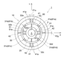
図15に示すように、起歪体30は、Z軸に沿って見たときに、Y軸に沿う長軸と、X軸に沿う短軸と、を有するように楕円形リング状に形成されていてもよい。この場合においても、受力体10、起歪体30および支持体20は、同心に形成されていていてもよい。起歪体30の幅は、全周にわたって一定であってもよい。なお、本実施の形態においては、各変形体31a~31dは、Z軸に沿って見たときに、起歪体30に沿う方向において、対応する受力体Y軸接続部41(または支持体Y軸接続部52)と対応する受力体X軸接続部42(または支持体X軸接続部51)との中間点に位置していてもよい。 As shown in FIG. 15, the strain body 30 is formed in an elliptical ring shape having a major axis along the Y axis and a minor axis along the X axis when viewed along the Z axis. may be In this case as well, the force receiving body 10, the strain generating body 30 and the support body 20 may be formed concentrically. The width of the strain generating body 30 may be constant over the entire circumference. In the present embodiment, each deformable body 31a to 31d has a corresponding force receiving body Y-axis connecting portion 41 (or support body It may be located at an intermediate point between the Y-axis connection portion 52) and the corresponding force receiving body X-axis connection portion 42 (or support body X-axis connection portion 51).

起歪体30のうち受力体Y軸接続部41が接続されている位置は、支持体20よりも受力体10に近い位置に配置されている。また、起歪体30のうち支持体X軸接続部51が接続されている位置は、受力体10よりも支持体20に近い位置に配置されている。このようにして、起歪体30のうち受力体Y軸接続部41が接続されている位置は、受力体X軸接続部42が接続されている位置よりも、受力体10に近い位置に配置されている。このことにより、受力体X軸接続部42のX軸方向の寸法(P2x)を、受力体Y軸接続部41のY軸方向の寸法(P1y)よりも大きくすることができる。また、起歪体30のうち支持体X軸接続部51が接続されている位置は、支持体Y軸接続部52が接続されている位置よりも、支持体20に近い位置に配置されている。このことにより、支持体Y軸接続部52のY軸方向の寸法(Q2y)を、支持体X軸接続部51のX軸方向の寸法(Q1x)よりも大きくすることができる。 The position where the force receiving body Y-axis connecting portion 41 is connected in the strain generating body 30 is located closer to the force receiving body 10 than the support body 20 is. In addition, the position of the strain body 30 to which the support X-axis connecting portion 51 is connected is located closer to the support 20 than the force receiving body 10 is. In this way, the position where the force receiving body Y-axis connecting portion 41 is connected in the strain body 30 is closer to the force receiving body 10 than the position where the force receiving body X-axis connecting portion 42 is connected. placed in position. As a result, the dimension (P2x) of the force receiving body X-axis connecting portion 42 in the X-axis direction can be made larger than the dimension (P1y) of the force receiving body Y-axis connecting portion 41 in the Y-axis direction. In addition, the position of the strain-generating body 30 to which the support X-axis connection portion 51 is connected is located closer to the support 20 than the position to which the support Y-axis connection portion 52 is connected. . As a result, the dimension (Q2y) in the Y-axis direction of the supporting body Y-axis connecting part 52 can be made larger than the dimension (Q1x) in the X-axis direction of the supporting body X-axis connecting part 51 .

上述したように、受力体X軸接続部42のX軸方向の寸法(P2x)が、受力体Y軸接続部41のY軸方向の寸法(P1y)よりも大きくなっている。このことにより、Z軸まわりのモーメントMzが作用した場合、受力体Y軸接続部41よりも受力体X軸接続部42が、ばね定数が小さくなり、弾性変形しやすくなる。受力体Y軸接続部41は、ばね定数が大きくなり、実質的に剛体として機能する。また、支持体Y軸接続部52のY軸方向の寸法(Q2y)が、支持体X軸接続部51のX軸方向の寸法(Q1x)よりも大きくなっている。このことにより、Z軸まわりのモーメントMzが作用した場合、支持体X軸接続部51よりも支持体Y軸接続部52が、ばね定数が小さくなり、弾性変形しやすくなる。支持体X軸接続部51は、ばね定数が大きくなり、実質的に剛体として機能する。 As described above, the X-axis dimension (P2x) of the force receiving X-axis connecting portion 42 is larger than the Y-axis dimension (P1y) of the force receiving Y-axis connecting portion 41 . As a result, when a moment Mz about the Z-axis acts, the force receiving body X-axis connecting portion 42 has a smaller spring constant than the force receiving body Y-axis connecting portion 41 and is more likely to be elastically deformed. The force receiving body Y-axis connecting portion 41 has a large spring constant and functions substantially as a rigid body. In addition, the dimension (Q2y) in the Y-axis direction of the supporting body Y-axis connecting part 52 is larger than the dimension (Q1x) in the X-axis direction of the supporting body X-axis connecting part 51 . As a result, when a moment Mz about the Z-axis acts, the support Y-axis connecting portion 52 has a smaller spring constant than the support X-axis connecting portion 51 and is more likely to be elastically deformed. The support X-axis connecting portion 51 has a large spring constant and functions substantially as a rigid body.

Z軸まわりのモーメントMzが作用した場合には、第1象限から第4象限に配置された起歪体30の各変形体31a~31dに、図8に示すような引張力または圧縮力を与えることができる。このため、各変形体31a~31dの変位部35をZ軸方向に変位させることができ、容量素子61a~61dを構成する変位電極62と固定電極63とを、Z軸方向で対向させるように配置させることができる。この場合、変位電極62と固定電極63の対向面をXY平面に沿うように配置することができ、変位電極62と固定電極63との位置合わせを容易化させることができる。この結果、トルクセンサ1の生産効率を向上させることができる。 When a moment Mz about the Z-axis acts, tensile force or compressive force as shown in FIG. be able to. Therefore, the displacement portion 35 of each deformable body 31a to 31d can be displaced in the Z-axis direction, and the displacement electrode 62 and the fixed electrode 63 constituting the capacitive elements 61a to 61d are arranged to face each other in the Z-axis direction. can be placed. In this case, the facing surfaces of the displacement electrode 62 and the fixed electrode 63 can be arranged along the XY plane, and the alignment of the displacement electrode 62 and the fixed electrode 63 can be facilitated. As a result, the production efficiency of the torque sensor 1 can be improved.

このように本実施の形態によれば、受力体X軸接続部42のX軸方向の寸法(P2x)は、受力体Y軸接続部41のY軸方向の寸法(P1y)よりも大きくなっているとともに、支持体Y軸接続部52のY軸方向の寸法(Q2y)は、支持体X軸接続部51のX軸方向の寸法(Q1x)よりも大きくなっている。このことにより、Z軸まわりのモーメントMzが作用した場合、受力体Y軸接続部41および支持体X軸接続部51を実質的に剛体として機能させることができるとともに、受力体X軸接続部42および支持体Y軸接続部52を容易に弾性変形させることができる。このため、第1象限から第4象限に配置された起歪体30の各変形体31a~31dに、引張力または圧縮力を容易に与えることができる。この結果、各変形体31a~31dの各変位部35を容易にZ軸方向に変位させることができ、容量素子61a~61dの静電容量値の変化を容易に検出することができる。 As described above, according to the present embodiment, the X-axis dimension (P2x) of the force receiving body X-axis connecting portion 42 is larger than the Y-axis dimension (P1y) of the force receiving body Y-axis connecting portion 41. In addition, the dimension (Q2y) in the Y-axis direction of the supporting body Y-axis connecting part 52 is larger than the dimension (Q1x) in the X-axis direction of the supporting body X-axis connecting part 51 . As a result, when a moment Mz about the Z-axis acts, the force receiving body Y-axis connection portion 41 and the support body X-axis connection portion 51 can be made to function substantially as rigid bodies, and the force receiving body X-axis connection The portion 42 and the support Y-axis connection portion 52 can be easily elastically deformed. Therefore, a tensile force or a compressive force can be easily applied to the deformation bodies 31a to 31d of the strain body 30 arranged in the first to fourth quadrants. As a result, the displacement portions 35 of the deformable bodies 31a-31d can be easily displaced in the Z-axis direction, and changes in the capacitance values of the capacitive elements 61a-61d can be easily detected.

また、本実施の形態によれば、起歪体30は、Z軸に沿って見たときに、Y軸に沿う長軸と、X軸に沿う短軸と、を有するように楕円形リング状に形成されている。このことにより、各変形体31a~31dを互いに接続することができる。このため、Z軸まわりのモーメントMz以外の力またはモーメントが作用した場合であっても、起歪体30の各変形体31a~31dが弾性変形することを抑制できる。この結果、モーメントMz以外の力またはモーメントが作用した場合であっても、容量素子61a~61dの静電容量値が変化することを抑制でき、モーメントMz以外の力またはモーメントを検出することを抑制できる。また、起歪体30が上述のように楕円形リング状に形成されていることにより、受力体X軸接続部42のX軸方向の寸法(P2x)は、受力体Y軸接続部41のY軸方向の寸法(P1y)よりも大きくすることができるとともに、支持体Y軸接続部52のY軸方向の寸法(Q2y)は、支持体X軸接続部51のX軸方向の寸法(Q1x)よりも大きくすることができる。 Further, according to the present embodiment, the strain body 30 has an elliptical ring shape having a major axis along the Y axis and a minor axis along the X axis when viewed along the Z axis. is formed in This allows the deformable bodies 31a to 31d to be connected to each other. Therefore, even when a force or moment other than the moment Mz about the Z-axis acts, elastic deformation of the deformable bodies 31a to 31d of the strain generating body 30 can be suppressed. As a result, even when a force or moment other than the moment Mz acts, it is possible to suppress changes in the capacitance values of the capacitive elements 61a to 61d, and to suppress detection of forces or moments other than the moment Mz. can. Further, since the strain body 30 is formed in an elliptical ring shape as described above, the dimension (P2x) in the X-axis direction of the force receiving body X-axis connecting portion 42 is equal to that of the force receiving body Y-axis connecting portion 41 can be made larger than the dimension (P1y) in the Y-axis direction of the support body Y-axis connection part 52, and the dimension (Q2y) in the Y-axis direction of the support body Y-axis connection part 52 is equal to the dimension in the X-axis direction of the support body X-axis connection part 51 ( Q1x).

なお、上述した本実施の形態においては、起歪体30は、Z軸に沿って見たときに、Y軸に沿う長軸と、X軸に沿う短軸と、を有するように楕円形リング状に形成されている例について説明した。しかしながら、このことに限られることはない。 In the above-described embodiment, the strain-generating body 30 is an elliptical ring having a long axis along the Y-axis and a short axis along the X-axis when viewed along the Z-axis. An example in which it is formed in a shape has been described. However, it is not limited to this.

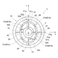
例えば、図16に示すように、起歪体30は、Z軸に沿って見たときに、円形リング状に形成されて、受力体10および支持体20に同心に形成されていてもよい。図16は、図15のトルクセンサの変形例を示す平面図である。 For example, as shown in FIG. 16, the strain body 30 may be formed in a circular ring shape when viewed along the Z-axis, and may be formed concentrically with the force receiving body 10 and the support body 20. . 16 is a plan view showing a modification of the torque sensor of FIG. 15. FIG.

この場合、受力体Y軸接続部41と起歪体30との間に、付根部85が介在されていてもよい。付根部85は、受力体10に作用する力またはモーメントに対してばね定数が大きく、実質的に剛体として機能するように形成されていてもよい。受力体X軸接続部42は、起歪体30に直接的に接続されていてもよい。このことにより、受力体X軸接続部42のX軸方向の寸法(P2x)を、受力体Y軸接続部41のY軸方向の寸法(P1y)よりも大きくすることができる。付根部85は、受力体Y軸接続部41と起歪体30との間ではなく、受力体10と受力体Y軸接続部41との間に介在されていてもよい。あるいは、付根部85は、受力体10と受力体Y軸接続部41との間、および受力体Y軸接続部41と起歪体30との間の両方に介在されていてもよい。 In this case, a root portion 85 may be interposed between the force receiving body Y-axis connecting portion 41 and the strain body 30 . The base portion 85 may be formed so as to have a large spring constant with respect to the force or moment acting on the force receiving member 10 and function substantially as a rigid body. The force receiving body X-axis connecting portion 42 may be directly connected to the strain generating body 30 . As a result, the dimension (P2x) of the force receiving body X-axis connecting portion 42 in the X-axis direction can be made larger than the dimension (P1y) of the force receiving body Y-axis connecting portion 41 in the Y-axis direction. The base portion 85 may be interposed between the force receiving body 10 and the force receiving body Y-axis connecting portion 41 instead of between the force receiving body Y-axis connecting portion 41 and the strain body 30 . Alternatively, root portion 85 may be interposed both between force receiving body 10 and force receiving body Y-axis connecting portion 41 and between force receiving body Y-axis connecting portion 41 and strain body 30 . .

同様に、起歪体30と支持体X軸接続部51との間に、上述した付根部85と同様な付根部86が介在されていてもよい。付根部86は、起歪体30と支持体X軸接続部51との間ではなく、支持体X軸接続部51と支持体20との間に介在されていてもよい。あるいは、付根部86は、起歪体30と支持体X軸接続部51との間、および支持体X軸接続部51と支持体20との間の両方に介在されていてもよい。 Similarly, a root portion 86 similar to the root portion 85 described above may be interposed between the strain-generating body 30 and the support X-axis connecting portion 51 . The base portion 86 may be interposed between the support X-axis connecting portion 51 and the support 20 instead of between the strain generating body 30 and the support X-axis connecting portion 51 . Alternatively, root portion 86 may be interposed both between strain-generating body 30 and support X-axis connecting portion 51 and between support X-axis connecting portion 51 and support 20 .

(第3の実施の形態)
次に、図17および図18を用いて、本発明の第3の実施の形態におけるトルクセンサについて説明する。
(Third Embodiment)
Next, a torque sensor according to a third embodiment of the invention will be described with reference to FIGS. 17 and 18. FIG.

図17および図18に示す第3の実施の形態においては、受力体Y軸接続部41が、受力体10と起歪体30との接続位置に形成されているとともに、支持体X軸接続部51が、起歪体30と支持体20との接続位置に形成されている点が主に異なり、他の構成は、図1~図14に示す第1の実施の形態と略同一である。なお、図17および図18において、図1~図14に示す第1の実施の形態と同一部分には同一符号を付して詳細な説明は省略する。 In the third embodiment shown in FIGS. 17 and 18, the force receiving body Y-axis connection portion 41 is formed at the connection position between the force receiving body 10 and the strain body 30, and the support body X-axis The main difference is that the connection portion 51 is formed at the connection position between the strain-generating body 30 and the support body 20, and other configurations are substantially the same as those of the first embodiment shown in FIGS. be. 17 and 18, the same parts as in the first embodiment shown in FIGS. 1 to 14 are denoted by the same reference numerals, and detailed description thereof will be omitted.

本実施の形態によるトルクセンサ1について、図17を参照して説明する。図17は、第3の実施の形態におけるトルクセンサを示す平面図である。 A torque sensor 1 according to this embodiment will be described with reference to FIG. FIG. 17 is a plan view showing a torque sensor according to the third embodiment; FIG.

本実施の形態によるトルクセンサ1においては、図17に示すように、受力体Y軸接続部41が、受力体10と起歪体30との接続位置に形成されている。起歪体30の外周面30cは、Z軸に沿って見たときに、Y軸に沿う長軸と、X軸に沿う短軸とを有するように楕円形状に形成されていてもよい。起歪体30の内周面30dは、Z軸に沿って見たときに、Y軸に沿う長軸と、X軸に沿う短軸とを有するように楕円形状に形成されていてもよい。図17に示す例では、起歪体30の幅は、全周にわたって一定であるが、これに限られることはなく、モーメントMz以外の力またはモーメントを検出することを抑制できれば、起歪体30の幅は、一定でなくてもよい。また、便宜上、図17に示す起歪体30の幅は、図15等に示す起歪体30よりも太く示しているが、本実施の形態による上述した受力体Y軸接続部41および後述する支持体X軸接続部51を形成することができれば、起歪体30の幅は、任意である。受力体10と起歪体30は、受力体X軸接続部42で接続されている。 In the torque sensor 1 according to the present embodiment, as shown in FIG. 17, the force receiving body Y-axis connecting portion 41 is formed at the connection position between the force receiving body 10 and the strain body 30 . The outer peripheral surface 30c of the strain generating body 30 may be formed in an elliptical shape having a major axis along the Y axis and a minor axis along the X axis when viewed along the Z axis. An inner peripheral surface 30d of the strain generating body 30 may be formed in an elliptical shape having a major axis along the Y axis and a minor axis along the X axis when viewed along the Z axis. In the example shown in FIG. 17, the width of the strain body 30 is constant over the entire circumference, but the width of the strain body 30 is not limited to this. width need not be constant. For convenience, the strain body 30 shown in FIG. 17 has a wider width than the strain body 30 shown in FIG. 15 and the like. The width of the strain body 30 is arbitrary as long as the supporting body X-axis connecting portion 51 can be formed. The force receiving body 10 and the strain generating body 30 are connected by a force receiving body X-axis connecting portion 42 .

起歪体30の第1起歪体接続部32aは、受力体10の内周面10cに接続されている。受力体X軸接続部42のY軸方向の寸法(P2y)は、受力体Y軸接続部41のX軸方向の寸法(P1x)よりも小さくなっている。このことにより、受力体Y軸接続部41は、Z軸まわりのモーメントMzに対してばね定数が大きくなり、実質的に剛体として機能している。受力体X軸接続部42は、Z軸まわりのモーメントMzに対して弾性変形しやすくなっている。 A first strain-generating body connecting portion 32 a of the strain-generating body 30 is connected to the inner peripheral surface 10 c of the force-receiving body 10 . The dimension (P2y) in the Y-axis direction of the force receiving body X-axis connection portion 42 is smaller than the dimension (P1x) in the X-axis direction of the force receiving body Y-axis connection portion 41 . As a result, the force receiving body Y-axis connecting portion 41 has a large spring constant with respect to the moment Mz about the Z-axis, and functions substantially as a rigid body. The force receiving body X-axis connecting portion 42 is easily elastically deformed by a moment Mz about the Z-axis.

支持体X軸接続部51が、起歪体30と支持体20との接続位置に形成されている。支持体20の外周面20cは、Z軸に沿って見たときに、X軸に沿う長軸と、Y軸に沿う短軸とを有するように楕円形状に形成されていてもよい。支持体20の内周面20dは、Z軸に沿って見たときに、円形状に形成されていてもよい。この内周面20dが、センサ開口2を画定している。図17においては、支持体20の内側には、トルクセンサ1の円形状のセンサ開口2が形成されている。起歪体30と支持体20は、支持体Y軸接続部52で接続されている。 A support X-axis connecting portion 51 is formed at a connection position between the strain-generating body 30 and the support 20 . The outer peripheral surface 20c of the support 20 may be formed in an elliptical shape having a major axis along the X axis and a minor axis along the Y axis when viewed along the Z axis. The inner peripheral surface 20d of the support 20 may be formed in a circular shape when viewed along the Z-axis. The inner peripheral surface 20d defines the sensor opening 2. As shown in FIG. In FIG. 17, inside the support 20, a circular sensor opening 2 of the torque sensor 1 is formed. The strain-generating body 30 and the support 20 are connected by a support Y-axis connecting portion 52 .

支持体20は、起歪体30(第2起歪体接続部32bおよび第4起歪体接続部32d)の内周面30dに接続されている。支持体Y軸接続部52のX軸方向の寸法(Q2x)は、支持体X軸接続部51のY軸方向の寸法(Q1y)よりも小さくなっている。このことにより、支持体X軸接続部51は、Z軸まわりのモーメントMzに対してばね定数が大きくなり、実質的に剛体として機能している。支持体Y軸接続部52は、Z軸まわりのモーメントMzに対して弾性変形しやすくなっている。 The support 20 is connected to the inner peripheral surface 30d of the strain body 30 (the second strain body connection portion 32b and the fourth strain body connection portion 32d). The X-axis dimension (Q2x) of the support Y-axis connecting portion 52 is smaller than the Y-axis dimension (Q1y) of the support X-axis connecting portion 51 . As a result, the support X-axis connecting portion 51 has a large spring constant with respect to the moment Mz about the Z-axis, and substantially functions as a rigid body. The support body Y-axis connecting portion 52 is easily elastically deformed against a moment Mz about the Z-axis.

Z軸まわりのモーメントMzが作用した場合には、第1象限から第4象限に配置された起歪体30の各変形体31a~31dに、図8に示すような引張力または圧縮力を与えることができる。このため、各変形体31a~31dの変位部35をZ軸方向に変位させることができ、容量素子61a~61dを構成する変位電極62と固定電極63とを、Z軸方向で対向させるように配置させることができる。この場合、変位電極62と固定電極63の対向面をXY平面に沿うように配置することができ、変位電極62と固定電極63との位置合わせを容易化させることができる。この結果、トルクセンサ1の生産効率を向上させることができる。 When a moment Mz about the Z-axis acts, tensile force or compressive force as shown in FIG. be able to. Therefore, the displacement portion 35 of each deformable body 31a to 31d can be displaced in the Z-axis direction, and the displacement electrode 62 and the fixed electrode 63 constituting the capacitive elements 61a to 61d are arranged to face each other in the Z-axis direction. can be placed. In this case, the facing surfaces of the displacement electrode 62 and the fixed electrode 63 can be arranged along the XY plane, and the alignment of the displacement electrode 62 and the fixed electrode 63 can be facilitated. As a result, the production efficiency of the torque sensor 1 can be improved.

このように本実施の形態によれば、受力体Y軸接続部41が、受力体10と起歪体30との接続位置に形成されるとともに、支持体X軸接続部51が、起歪体30と支持体20との接続位置に形成されている。このことにより、Z軸まわりのモーメントMzが作用した場合に、受力体Y軸接続部41および支持体X軸接続部51を実質的に剛体として機能させることができるとともに、受力体X軸接続部42および支持体Y軸接続部52を容易に弾性変形させることができる。このため、第1象限から第4象限に配置された起歪体30の各変形体31a~31dに引張力または圧縮力を容易に与えることができる。この結果、各変形体31a~31dの各変位部35を容易にZ軸方向に変位させることができ、容量素子61a~61dの静電容量値の変化を容易に検出することができる。 As described above, according to the present embodiment, the force receiving body Y-axis connection portion 41 is formed at the connection position between the force receiving body 10 and the strain body 30, and the support body X-axis connection portion 51 It is formed at the connection position between the strain body 30 and the support body 20 . As a result, when a moment Mz about the Z-axis acts, the force receiving body Y-axis connecting portion 41 and the support body X-axis connecting portion 51 can be made to function substantially as rigid bodies, and the force receiving body X-axis The connection portion 42 and the support Y-axis connection portion 52 can be easily elastically deformed. Therefore, a tensile force or a compressive force can be easily applied to the deformation bodies 31a to 31d of the strain body 30 arranged in the first to fourth quadrants. As a result, the displacement portions 35 of the deformable bodies 31a-31d can be easily displaced in the Z-axis direction, and changes in the capacitance values of the capacitive elements 61a-61d can be easily detected.

また、本実施の形態によれば、起歪体30の外周面30cは、Z軸に沿って見たときに、Y軸に沿う長軸と、X軸に沿う短軸とを有するように楕円形に形成されている。このことにより、起歪体30を、受力体10の内周面10cに接続することができ、受力体10と起歪体30との接続位置に、受力体Y軸接続部41を形成することができる。このため、受力体Y軸接続部41を、Z軸まわりのモーメントMzに対して実質的に剛体として機能させることができる。 Further, according to the present embodiment, the outer peripheral surface 30c of the strain body 30 is an ellipse having a major axis along the Y axis and a minor axis along the X axis when viewed along the Z axis. formed into a shape. As a result, the strain body 30 can be connected to the inner peripheral surface 10 c of the force receiving body 10 , and the force receiving body Y-axis connection portion 41 is provided at the connection position between the force receiving body 10 and the strain body 30 . can be formed. Therefore, the force receiving body Y-axis connecting portion 41 can function as a substantially rigid body against the moment Mz about the Z-axis.

また、本実施の形態によれば、支持体20の外周面20cは、Z軸に沿って見たときに、X軸に沿う長軸と、Y軸に沿う短軸とを有するように楕円形に形成されている。このことにより、支持体20を、起歪体30の内周面30dに接続することができ、起歪体30と支持体20との接続位置に支持体X軸接続部51を形成することができる。このため、支持体X軸接続部51を、Z軸まわりのモーメントMzに対して実質的に剛体として機能させることができる。 Further, according to the present embodiment, the outer peripheral surface 20c of the support 20 is elliptical so as to have a major axis along the X-axis and a minor axis along the Y-axis when viewed along the Z-axis. is formed in As a result, the support body 20 can be connected to the inner peripheral surface 30d of the strain body 30, and the support body X-axis connecting portion 51 can be formed at the connection position between the strain body 30 and the support body 20. can. Therefore, the support X-axis connecting portion 51 can function as a substantially rigid body against the moment Mz about the Z-axis.

また、本実施の形態によれば、受力体X軸接続部42のY軸方向の寸法(P2Y)が、受力体Y軸接続部41のX軸方向の寸法(P1x)よりも小さくなっているとともに、支持体Y軸接続部52のX軸方向の寸法(Q2x)が、支持体X軸接続部51のY軸方向の寸法(Q1y)よりも小さくなっている。このことにより、Z軸まわりのモーメントMzが作用した場合、受力体Y軸接続部41および支持体X軸接続部51を実質的に剛体として機能させることができるとともに、受力体X軸接続部42および支持体Y軸接続部52を容易に弾性変形させることができる。このため、第1象限から第4象限に配置された起歪体30の各変形体31a~31dに引張力または圧縮力を容易に与えることができる。この結果、各変形体31a~31dの各変位部35を容易にZ軸方向に変位させることができ、容量素子61a~61dの静電容量値の変化を容易に検出することができる。 Further, according to the present embodiment, the Y-axis dimension (P2Y) of the force receiving body X-axis connecting portion 42 is smaller than the X-axis dimension (P1x) of the force receiving body Y-axis connecting portion 41. In addition, the X-axis dimension (Q2x) of the support Y-axis connecting portion 52 is smaller than the Y-axis dimension (Q1y) of the support X-axis connecting portion 51 . As a result, when a moment Mz about the Z-axis acts, the force receiving body Y-axis connection portion 41 and the support body X-axis connection portion 51 can be made to function substantially as rigid bodies, and the force receiving body X-axis connection The portion 42 and the support Y-axis connection portion 52 can be easily elastically deformed. Therefore, a tensile force or a compressive force can be easily applied to the deformation bodies 31a to 31d of the strain body 30 arranged in the first to fourth quadrants. As a result, the displacement portions 35 of the deformable bodies 31a-31d can be easily displaced in the Z-axis direction, and changes in the capacitance values of the capacitive elements 61a-61d can be easily detected.

なお、上述した本実施の形態においては、支持体20の外周面20cが、Z軸に沿って見たときに、X軸に沿う長軸と、Y軸に沿う短軸とを有するように楕円形状に形成されている例について説明した。しかしながら、このことに限られることはない。例えば、支持体20の外周面20cは、図2等に示すように、円形状に形成されていてもよい。また、支持体20の内周面20dは、Z軸に沿って見たときに、X軸に沿う長軸と、Y軸に沿う短軸とを有するように楕円形状に形成されていてもよい。 In the above-described embodiment, the outer peripheral surface 20c of the support 20 is an ellipse having a major axis along the X axis and a minor axis along the Y axis when viewed along the Z axis. An example in which it is formed into a shape has been described. However, it is not limited to this. For example, the outer peripheral surface 20c of the support 20 may be circular as shown in FIG. 2 and the like. In addition, the inner peripheral surface 20d of the support 20 may be formed in an elliptical shape having a long axis along the X axis and a short axis along the Y axis when viewed along the Z axis. .

また、上述した本実施の形態においては、受力体10と起歪体30が、受力体X軸接続部42で接続されるとともに、起歪体30と支持体20が、支持体Y軸接続部52で接続されている例について説明した。しかしながら、このことに限られることはない。 In the above-described embodiment, the force receiving body 10 and the strain body 30 are connected by the force receiving body X-axis connecting portion 42, and the strain body 30 and the support body 20 are connected to the support body Y axis. An example in which they are connected by the connection portion 52 has been described. However, it is not limited to this.

例えば、図18に示すように、起歪体30のうち受力体Y軸接続部41が接続された位置では、起歪体30と支持体20とは接続されていなくてもよい。すなわち、第1起歪体接続部32aおよび第3起歪体接続部32cは、支持体20と、図17に示すような支持体Y軸接続部52で接続されていなくてもよい。また、起歪体30のうち支持体X軸接続部51で接続された位置では、受力体10と起歪体30とが接続されていなくてもよい。すなわち、第2起歪体接続部32bおよび第4起歪体接続部32dは、受力体10と、図17に示すような受力体X軸接続部42で接続されていなくてもよい。図18は、図17のトルクセンサの変形例を示す平面図である。 For example, as shown in FIG. 18 , the strain body 30 and the support body 20 may not be connected at the position where the force receiving body Y-axis connection portion 41 is connected in the strain body 30 . That is, the first strain-generating body connecting portion 32a and the third strain-generating body connecting portion 32c may not be connected to the support 20 by the support Y-axis connecting portion 52 as shown in FIG. Further, the force receiving body 10 and the strain body 30 may not be connected at the position where the strain body 30 is connected by the support body X-axis connection portion 51 . That is, the second strain-generating body connecting portion 32b and the fourth strain-generating body connecting portion 32d may not be connected to the force receiving body 10 by the force receiving body X-axis connecting portion 42 as shown in FIG. 18 is a plan view showing a modification of the torque sensor of FIG. 17. FIG.

図18に示すトルクセンサにおいても、受力体10と起歪体30が受力体Y軸接続部41で接続されるとともに、起歪体30と支持体20が支持体X軸接続部51で接続されている。このことにより、Z軸まわりのモーメントMzが作用した場合には、第1象限から第4象限に配置された起歪体30の各変形体31a~31dに、引張力または圧縮力を与えることができる。このため、各変形体31a~31dの変位部35をZ軸方向に変位させることができ、容量素子61a~61dを構成する変位電極62と固定電極63とを、Z軸方向で対向させるように配置させることができる。この場合、変位電極62と固定電極63の対向面をXY平面に沿うように配置することができ、変位電極62と固定電極63との位置合わせを容易化させることができる。この結果、トルクセンサ1の生産効率を向上させることができる。 In the torque sensor shown in FIG. 18 as well, the force receiving body 10 and the strain body 30 are connected by the force receiving body Y-axis connection portion 41, and the strain body 30 and the support body 20 are connected by the support body X-axis connection portion 51. It is connected. As a result, when a moment Mz about the Z-axis acts, a tensile force or a compressive force can be applied to each of the deformable bodies 31a to 31d of the strain body 30 arranged in the first to fourth quadrants. can. Therefore, the displacement portion 35 of each deformable body 31a to 31d can be displaced in the Z-axis direction, and the displacement electrode 62 and the fixed electrode 63 constituting the capacitive elements 61a to 61d are arranged to face each other in the Z-axis direction. can be placed. In this case, the facing surfaces of the displacement electrode 62 and the fixed electrode 63 can be arranged along the XY plane, and the alignment of the displacement electrode 62 and the fixed electrode 63 can be facilitated. As a result, the production efficiency of the torque sensor 1 can be improved.

このように図18に示す変形例によれば、起歪体30のうち受力体Y軸接続部41が接続された位置では、起歪体30と支持体20とは接続されておらず、起歪体30のうち支持体X軸接続部51が接続された位置では、受力体10と起歪体30とは接続されていない。このことにより、トルクセンサ1の生産効率を向上させながら、トルクセンサ1の構造を簡素化させることができ、低価格化を図ることができる。 As described above, according to the modification shown in FIG. 18, the strain body 30 and the support body 20 are not connected at the position where the force receiving body Y-axis connection portion 41 of the strain body 30 is connected. The force receiving body 10 and the strain body 30 are not connected at the position of the strain body 30 where the support body X-axis connecting portion 51 is connected. As a result, the structure of the torque sensor 1 can be simplified while the production efficiency of the torque sensor 1 is improved, and the price can be reduced.

(第4の実施の形態)
次に、図19~図22を用いて、本発明の第4の実施の形態におけるトルクセンサについて説明する。
(Fourth embodiment)
Next, a torque sensor according to a fourth embodiment of the invention will be described with reference to FIGS. 19 to 22. FIG.

図19~図22に示す第4の実施の形態においては、起歪体30が、受力体10に対してZ軸の負側に配置されているとともに、支持体20が、起歪体30に対してZ軸の負側に配置されている点が主に異なり、他の構成は、図1~図14に示す第1の実施の形態と略同一である。なお、図19~図22において、図1~図14に示す第1の実施の形態と同一部分には同一符号を付して詳細な説明は省略する。 In the fourth embodiment shown in FIGS. 19 to 22, the strain body 30 is arranged on the negative side of the Z-axis with respect to the force receiving body 10, and the support body 20 The main difference is that it is arranged on the negative side of the Z-axis, and the other configurations are substantially the same as those of the first embodiment shown in FIGS. 19 to 22, the same parts as in the first embodiment shown in FIGS. 1 to 14 are denoted by the same reference numerals, and detailed description thereof will be omitted.

本実施の形態によるトルクセンサ1について、図19~図21を参照して説明する。図19は、第4の実施の形態におけるトルクセンサを示す断面図である。図20は、図19のB-B線断面図であり、図21は、図19のC-C線断面図である。 A torque sensor 1 according to this embodiment will be described with reference to FIGS. 19 to 21. FIG. FIG. 19 is a cross-sectional view showing a torque sensor according to the fourth embodiment. 20 is a cross-sectional view taken along line BB of FIG. 19, and FIG. 21 is a cross-sectional view taken along line CC of FIG.

本実施の形態によるトルクセンサ1においては、図19に示すように、起歪体30は、受力体10に対してZ軸の負側に配置されている。支持体20は、起歪体30に対してZ軸の負側に配置されている。すなわち、受力体10、起歪体30および支持体20が、Z軸方向に積層されている。受力体10、起歪体30および支持体20は、Z軸に沿って見たときに、それぞれ円形リング状に形成されていてもよく、互いに同心に形成されていてもよい。図20および図21に示すように、受力体10の内側、起歪体30の内側および支持体20の内側に、トルクセンサ1のセンサ開口2が形成されている。 In the torque sensor 1 according to the present embodiment, the strain body 30 is arranged on the negative side of the Z axis with respect to the force receiving body 10, as shown in FIG. The support 20 is arranged on the negative side of the Z-axis with respect to the strain-generating body 30 . That is, the force-receiving body 10, the strain-generating body 30, and the support body 20 are laminated in the Z-axis direction. The force-receiving body 10, the strain-generating body 30, and the support body 20 may each be formed in a circular ring shape when viewed along the Z-axis, or may be formed concentrically with each other. As shown in FIGS. 20 and 21, the sensor opening 2 of the torque sensor 1 is formed inside the force receiving member 10, inside the strain generating member 30, and inside the support member 20. FIG.

図19に示すように、本実施の形態における受力体Y軸接続部41は、Z軸方向において、受力体10と起歪体30との間に配置されている。図20に示すように、受力体Y軸接続部41は、Z軸に沿って見たときに、受力体10および起歪体30に重なっている。受力体Y軸接続部41は、Y軸に沿って延びているとともに、Z軸に沿って延びている。本実施の形態においては、受力体Y軸接続部41は、X軸、Y軸およびZ軸に沿って矩形状に形成されている。受力体Y軸接続部41のZ軸方向の寸法は、受力体Y軸接続部41のY軸方向の寸法(P1y)よりも大きくなっていてもよいが、大きくなっていなくてもよい。 As shown in FIG. 19, the force receiving body Y-axis connecting portion 41 in the present embodiment is arranged between the force receiving body 10 and the strain body 30 in the Z-axis direction. As shown in FIG. 20, the force receiving body Y-axis connecting portion 41 overlaps the force receiving body 10 and the strain body 30 when viewed along the Z axis. The force receiving body Y-axis connecting portion 41 extends along the Y-axis and along the Z-axis. In this embodiment, the force receiving body Y-axis connecting portion 41 is formed in a rectangular shape along the X-, Y-, and Z-axes. The Z-axis direction dimension of the force receiving Y-axis connecting portion 41 may be larger than the Y-axis direction dimension (P1y) of the force receiving Y-axis connecting portion 41, but it does not have to be larger. .

図19に示すように、本実施の形態における受力体X軸接続部42は、Z軸方向において、受力体10と起歪体30との間に配置されている。図20に示すように、受力体X軸接続部42は、Z軸に沿って見たときに、受力体10および起歪体30に重なっている。受力体X軸接続部42は、X軸に沿って延びているとともに、Z軸に沿って延びている。本実施の形態においては、受力体X軸接続部42は、X軸、Y軸およびZ軸に沿って矩形状に形成されている。受力体X軸接続部42のZ軸方向の寸法は、受力体X軸接続部42のX軸方向の寸法(P2x)よりも大きくなっていてもよいが、大きくなっていなくてもよい。 As shown in FIG. 19, the force receiving body X-axis connecting portion 42 in the present embodiment is arranged between the force receiving body 10 and the strain body 30 in the Z-axis direction. As shown in FIG. 20, the force receiving body X-axis connecting portion 42 overlaps the force receiving body 10 and the strain body 30 when viewed along the Z axis. The force receiving body X-axis connecting portion 42 extends along the X-axis and along the Z-axis. In this embodiment, the force receiving body X-axis connecting portion 42 is formed in a rectangular shape along the X-, Y-, and Z-axes. The dimension of the force receiving X-axis connecting portion 42 in the Z-axis direction may be larger than the dimension (P2x) of the force receiving X-axis connecting portion 42 in the X-axis direction, but it does not have to be larger. .

本実施の形態においては、起歪体30の変形体31a~31dの変位部35は、支持体20の上面20aに対向していてもよい。この場合、容量素子61a~61dを構成する固定電極63は、支持体20の上面20aに設けられていてもよい。しかしながら、このことに限られることはなく、変位部35が、受力体10の下面10bに対向していてもよい。この場合、固定電極63は、受力体10の下面10bに設けられていてもよい。 In the present embodiment, the displacement portions 35 of the deformable bodies 31 a to 31 d of the strain body 30 may face the upper surface 20 a of the support 20 . In this case, the fixed electrodes 63 forming the capacitive elements 61 a to 61 d may be provided on the upper surface 20 a of the support 20 . However, it is not limited to this, and the displacement portion 35 may face the lower surface 10 b of the force receiving member 10 . In this case, the fixed electrode 63 may be provided on the lower surface 10 b of the force receiving member 10 .

図20に示すように、本実施の形態においては、受力体X軸接続部42のY軸方向の寸法(P2y)は、受力体Y軸接続部41のX軸方向の寸法(P1x)よりも小さくなっている。 As shown in FIG. 20, in the present embodiment, the dimension (P2y) of the force receiving body X-axis connecting portion 42 in the Y-axis direction is equal to the dimension (P1x) of the force receiving body Y-axis connecting portion 41 in the X-axis direction. is smaller than

図19に示すように、本実施の形態における支持体X軸接続部51は、Z軸方向において、起歪体30と支持体20との間に配置されている。図21に示すように、支持体X軸接続部51は、Z軸に沿って見たときに、起歪体30および支持体20に重なっている。支持体X軸接続部51は、X軸に沿って延びているとともにZ軸に沿って延びている。本実施の形態においては、支持体X軸接続部51は、X軸、Y軸およびZ軸に沿って矩形状に形成されている。支持体X軸接続部51のZ軸方向の寸法は、支持体X軸接続部51のX軸方向の寸法(Q1x)よりも大きくなっていてもよいが、大きくなっていなくてもよい。 As shown in FIG. 19, the support X-axis connecting portion 51 in the present embodiment is arranged between the strain-generating body 30 and the support 20 in the Z-axis direction. As shown in FIG. 21, the support X-axis connecting portion 51 overlaps the strain-generating body 30 and the support 20 when viewed along the Z-axis. The support X-axis connecting portion 51 extends along the X-axis and along the Z-axis. In this embodiment, the support X-axis connecting portion 51 is formed in a rectangular shape along the X-, Y-, and Z-axes. The dimension of the support X-axis connection portion 51 in the Z-axis direction may be larger than the dimension (Q1x) of the support X-axis connection portion 51 in the X-axis direction, but it does not have to be larger.

図19に示すように、本実施の形態における支持体Y軸接続部52は、Z軸方向において、起歪体30と支持体20との間に配置されている。図21に示すように、支持体Y軸接続部52は、Z軸に沿って見たときに、起歪体30および支持体20に重なっている。支持体Y軸接続部52は、Y軸に沿って延びているとともにZ軸に沿って延びている。本実施の形態においては、支持体Y軸接続部52は、X軸、Y軸およびZ軸に沿って矩形状に形成されている。支持体Y軸接続部52のZ軸方向の寸法は、支持体Y軸接続部52のY軸方向の寸法(Q2y)よりも大きくなっていてもよいが、大きくなっていなくてもよい。 As shown in FIG. 19, the support Y-axis connecting portion 52 in the present embodiment is arranged between the strain-generating body 30 and the support 20 in the Z-axis direction. As shown in FIG. 21, the support Y-axis connecting portion 52 overlaps the strain body 30 and the support 20 when viewed along the Z-axis. The support Y-axis connecting portion 52 extends along the Y-axis and along the Z-axis. In this embodiment, the support Y-axis connecting portion 52 is formed in a rectangular shape along the X-, Y-, and Z-axes. The Z-axis direction dimension of the support Y-axis connecting portion 52 may be larger than the Y-axis direction dimension (Q2y) of the support Y-axis connecting portion 52, but does not have to be larger.

図21に示すように、本実施の形態においては、支持体Y軸接続部52のX軸方向の寸法(Q2x)は、支持体X軸接続部51のY軸方向の寸法(Q1y)よりも小さくなっている。 As shown in FIG. 21, in the present embodiment, the X-axis dimension (Q2x) of the support Y-axis connection portion 52 is larger than the Y-axis dimension (Q1y) of the support X-axis connection portion 51. It's getting smaller.

Z軸まわりのモーメントMzが作用した場合、受力体Y軸接続部41が実質的に剛体として機能し、受力体X軸接続部42が弾性変形する。また、支持体X軸接続部51が実質的に剛体として機能し、支持体Y軸接続部52が弾性変形する。このことにより、第1象限から第4象限に配置された起歪体30の各変形体31a~31dに、図8に示すような引張力または圧縮力を与えることができる。このため、各変形体31a~31dの変位部35をZ軸方向に変位させることができ、容量素子61a~61dを構成する変位電極62と固定電極63とを、Z軸方向で対向させるように配置させることができる。この場合、変位電極62と固定電極63の対向面をXY平面に沿うように配置することができ、変位電極62と固定電極63との位置合わせを容易化させることができる。この結果、トルクセンサ1の生産効率を向上させることができる。 When a moment Mz about the Z-axis acts, the force receiving body Y-axis connecting portion 41 functions substantially as a rigid body, and the force receiving body X-axis connecting portion 42 elastically deforms. Further, the support body X-axis connection portion 51 functions substantially as a rigid body, and the support body Y-axis connection portion 52 is elastically deformed. As a result, a tensile force or a compressive force as shown in FIG. 8 can be applied to the deformation bodies 31a to 31d of the strain body 30 arranged in the first to fourth quadrants. Therefore, the displacement portion 35 of each deformable body 31a to 31d can be displaced in the Z-axis direction, and the displacement electrode 62 and the fixed electrode 63 constituting the capacitive elements 61a to 61d are arranged to face each other in the Z-axis direction. can be placed. In this case, the facing surfaces of the displacement electrode 62 and the fixed electrode 63 can be arranged along the XY plane, and the alignment of the displacement electrode 62 and the fixed electrode 63 can be facilitated. As a result, the production efficiency of the torque sensor 1 can be improved.

このように本実施の形態によれば、支持体20は、起歪体30に対してZ軸の負側に配置されている。このことにより、トルクセンサ1のセンサ開口2を、大きくすることができる。トルクセンサ1は、ロボットに適用される場合、ロボットで用いられるケーブルおよびチューブをトルクセンサ1のセンサ開口2に通すことが多い。このため、本実施の形態のように、起歪体30および支持体20をZ軸方向に積層した場合には、トルクセンサ1のセンサ開口2を大きくすることができ、ケーブルおよびチューブを容易に通すことができる。トルクセンサ1の使い勝手を向上させることができる。 Thus, according to this embodiment, the support 20 is arranged on the negative side of the Z-axis with respect to the strain-generating body 30 . As a result, the sensor opening 2 of the torque sensor 1 can be enlarged. When the torque sensor 1 is applied to a robot, cables and tubes used in the robot are often passed through the sensor opening 2 of the torque sensor 1 . Therefore, when the strain-generating body 30 and the support body 20 are stacked in the Z-axis direction as in the present embodiment, the sensor opening 2 of the torque sensor 1 can be enlarged, and cables and tubes can be easily installed. can pass. The usability of the torque sensor 1 can be improved.

また、本実施の形態によれば、起歪体30は、受力体10に対してZ軸の負側に配置されている。このことにより、トルクセンサ1のセンサ開口2を、より一層大きくすることができる。このため、ロボットで用いられるケーブルおよびチューブをより一層容易に通すことができ、トルクセンサ1の使い勝手をより一層向上させることができる。 Further, according to the present embodiment, the strain body 30 is arranged on the negative side of the Z axis with respect to the force receiving body 10 . As a result, the sensor opening 2 of the torque sensor 1 can be made even larger. Therefore, the cables and tubes used in the robot can be passed more easily, and the usability of the torque sensor 1 can be further improved.

また、本実施の形態によれば、受力体X軸接続部42と支持体X軸接続部51は、X軸に沿ってそれぞれ延びている。このことにより、受力体10にX軸方向の力Fyが作用した場合であっても、受力体X軸接続部42および支持体X軸接続部51が実質的に剛体として機能することができ、起歪体30の各変形体31a~31dが弾性変形することを抑制できる。このため、X軸方向の力Fxが作用した場合であっても、各容量素子61a~61dの静電容量値が変化することを抑制でき、力Fxを検出することを抑制できる。 Further, according to the present embodiment, the force receiving body X-axis connection portion 42 and the support body X-axis connection portion 51 each extend along the X-axis. As a result, even when the force Fy in the X-axis direction acts on the force receiving body 10, the force receiving body X-axis connection portion 42 and the support body X-axis connection portion 51 can function substantially as rigid bodies. Therefore, elastic deformation of the deformable bodies 31a to 31d of the strain generating body 30 can be suppressed. Therefore, even when the force Fx in the X-axis direction acts, it is possible to suppress changes in the capacitance values of the capacitive elements 61a to 61d, and to suppress detection of the force Fx.

また、本実施の形態によれば、受力体Y軸接続部41および支持体Y軸接続部52は、Y軸に沿ってそれぞれ延びている。このことにより、受力体10にY軸方向の力Fyが作用した場合であっても、受力体Y軸接続部41および支持体Y軸接続部52が実質的に剛体として機能することができ、起歪体30の各変形体31a~31dが弾性変形することを抑制できる。このため、Y軸方向の力Fyが作用した場合であっても、各容量素子61a~61dの静電容量値が変化することを抑制でき、力Fyを検出することを抑制できる。 Further, according to the present embodiment, the force receiving body Y-axis connecting portion 41 and the supporting body Y-axis connecting portion 52 each extend along the Y-axis. As a result, even when the force Fy in the Y-axis direction acts on the force receiving member 10, the force receiving member Y-axis connection portion 41 and the support member Y-axis connection portion 52 can function as substantially rigid bodies. Therefore, elastic deformation of the deformable bodies 31a to 31d of the strain generating body 30 can be suppressed. Therefore, even when the force Fy in the Y-axis direction acts, it is possible to suppress changes in the capacitance values of the capacitive elements 61a to 61d, and to suppress detection of the force Fy.

また、本実施の形態によれば、受力体Y軸接続部41、受力体X軸接続部42、支持体X軸接続部51および支持体Y軸接続部52は、Z軸に沿ってそれぞれ延びている。このことにより、各接続部41、42、51、52を、Z軸方向の力に対して実質的に剛体として機能させることができる。このため、受力体10にZ軸方向の力Fzが作用した場合であっても、起歪体30の各変形体31a~31dが弾性変形することを抑制できる。同様に、受力体10にX軸まわりのモーメントMxおよびY軸まわりのモーメントMyが作用した場合であっても、起歪体30の各変形体31a~31dが弾性変形することを抑制できる。このため、力Fz、モーメントMxまたはモーメントMyが作用した場合であっても、各容量素子61a~61dの静電容量値が変化することを抑制でき、力Fz、モーメントMxおよびモーメントMyを検出することを抑制できる。 Further, according to the present embodiment, the force receiving body Y-axis connection portion 41, the force receiving body X-axis connection portion 42, the support body X-axis connection portion 51, and the support body Y-axis connection portion 52 are arranged along the Z-axis. each extended. As a result, each connecting portion 41, 42, 51, 52 can function as a substantially rigid body against force in the Z-axis direction. Therefore, even when the force Fz in the Z-axis direction acts on the force receiving member 10, elastic deformation of the deformable members 31a to 31d of the strain generating member 30 can be suppressed. Similarly, even when a moment Mx about the X-axis and a moment My about the Y-axis act on the force receiving member 10, elastic deformation of the deformable bodies 31a to 31d of the strain generating body 30 can be suppressed. Therefore, even when the force Fz, the moment Mx, or the moment My acts, it is possible to suppress changes in the capacitance values of the capacitive elements 61a to 61d, and the force Fz, the moment Mx, and the moment My can be detected. can be suppressed.

また、本実施の形態によれば、受力体X軸接続部42のY軸方向の寸法(P2y)が、受力体Y軸接続部41のX軸方向の寸法(P1x)よりも小さくなっているとともに、支持体Y軸接続部52のX軸方向の寸法(Q2x)が、支持体X軸接続部51のY軸方向の寸法(Q1y)よりも小さくなっている。このことにより、Z軸まわりのモーメントMzが作用した場合、受力体Y軸接続部41および支持体X軸接続部51を実質的に剛体として機能させることができるとともに、受力体X軸接続部42および支持体Y軸接続部52を容易に弾性変形させることができる。このため、第1象限から第4象限に配置された起歪体30の各変形体31a~31dに引張力または圧縮力を容易に与えることができる。この結果、各変形体31a~31dの各変位部35を容易にZ軸方向に変位させることができ、容量素子61a~61dの静電容量値の変化を容易に検出することができる。 Further, according to the present embodiment, the dimension (P2y) of the force receiving body X-axis connecting portion 42 in the Y-axis direction is smaller than the dimension (P1x) of the force receiving body Y-axis connecting portion 41 in the X-axis direction. In addition, the X-axis dimension (Q2x) of the support Y-axis connecting portion 52 is smaller than the Y-axis dimension (Q1y) of the support X-axis connecting portion 51 . As a result, when a moment Mz about the Z-axis acts, the force receiving body Y-axis connection portion 41 and the support body X-axis connection portion 51 can be made to function substantially as rigid bodies, and the force receiving body X-axis connection The portion 42 and the support Y-axis connection portion 52 can be easily elastically deformed. Therefore, a tensile force or a compressive force can be easily applied to the deformation bodies 31a to 31d of the strain body 30 arranged in the first to fourth quadrants. As a result, the displacement portions 35 of the deformable bodies 31a-31d can be easily displaced in the Z-axis direction, and changes in the capacitance values of the capacitive elements 61a-61d can be easily detected.

また、本実施の形態によれば、起歪体30は、Z軸に沿って見たときに、円形リング状に形成されている。このことにより、各変形体31a~31dを互いに接続することができる。このため、Z軸まわりのモーメントMz以外の力またはモーメントが作用した場合であっても、起歪体30の各変形体31a~31dが弾性変形することを抑制できる。この結果、モーメントMz以外の力またはモーメントが作用した場合であっても、容量素子61a~61dの静電容量値が変化することを抑制でき、モーメントMz以外の力またはモーメントを検出することを抑制できる。 Further, according to this embodiment, the strain body 30 is formed in a circular ring shape when viewed along the Z-axis. This allows the deformable bodies 31a to 31d to be connected to each other. Therefore, even when a force or moment other than the moment Mz about the Z-axis acts, elastic deformation of the deformable bodies 31a to 31d of the strain generating body 30 can be suppressed. As a result, even when a force or moment other than the moment Mz acts, it is possible to suppress changes in the capacitance values of the capacitive elements 61a to 61d, and to suppress detection of forces or moments other than the moment Mz. can.

なお、上述した本実施の形態においては、起歪体30が、受力体10に対してZ軸の負側に配置されるとともに、支持体20が、起歪体30に対してZ軸の負側に配置されている例について説明した。しかしながら、このことに限られることはない。例えば、図22に示すように、受力体10と起歪体30をXY平面に沿うように配置して、支持体20を起歪体30に対してZ軸の負側に配置するようにしてもよい。この場合においても、図19に示すトルクセンサ1と同様の効果を奏することができるとともに、トルクセンサ1の高さ寸法を低減することができる。また、この場合、検出素子60の固定電極63は、支持体20の上面20aに取り付けられていてもよい。図22は、図19のトルクセンサの変形例を示す断面図であって、図2のA-A線断面に相当する図である。 In the present embodiment described above, the strain body 30 is arranged on the negative side of the Z axis with respect to the force receiving body 10, and the support body 20 is located on the Z axis side with respect to the strain body 30. An example in which it is arranged on the negative side has been described. However, it is not limited to this. For example, as shown in FIG. 22, the force-receiving body 10 and the strain-generating body 30 are arranged along the XY plane, and the support body 20 is arranged on the negative side of the Z-axis with respect to the strain-generating body 30. may In this case as well, the same effects as those of the torque sensor 1 shown in FIG. 19 can be obtained, and the height dimension of the torque sensor 1 can be reduced. Also, in this case, the fixed electrode 63 of the detection element 60 may be attached to the upper surface 20 a of the support 20 . FIG. 22 is a cross-sectional view showing a modification of the torque sensor of FIG. 19, corresponding to the cross-section taken along the line AA of FIG.

本発明は上記実施の形態および変形例そのままに限定されるものではなく、実施段階ではその要旨を逸脱しない範囲で構成要素を変形して具体化できる。また、上記実施の形態および変形例に開示されている複数の構成要素の適宜な組み合わせにより、種々の発明を形成できる。実施の形態および変形例に示される全構成要素から幾つかの構成要素を削除してもよい。さらに、異なる実施の形態および変形例にわたる構成要素を適宜組み合わせてもよい。 The present invention is not limited to the above-described embodiments and modifications as they are, and can be embodied by modifying constituent elements without departing from the gist of the invention at the implementation stage. Also, various inventions can be formed by appropriate combinations of the plurality of constituent elements disclosed in the above embodiments and modifications. Some components may be deleted from all the components shown in the embodiment and modifications. Furthermore, components of different embodiments and modifications may be combined as appropriate.

Claims (8)

XYZ三次元座標系におけるZ軸まわりのモーメントを検出するトルクセンサであって、
前記Z軸を中心に形成された第1構造体と、
前記Z軸を中心に形成された第2構造体であって、前記Z軸に沿って見たときに前記第1構造体の内側に配置された第2構造体と、
前記第1構造体と前記第2構造体との間に設けられた起歪体であって、前記第1構造体と前記第2構造体とを接続し、前記モーメントの作用により弾性変形を生じる起歪体と、
前記第1構造体と前記起歪体とを接続する2つの第1構造体接続部と、
前記起歪体と前記第2構造体とを接続する2つの第2構造体接続部と、
検出素子と、
前記検出素子の検出結果に基づいて、前記モーメントを示す電気信号を出力する検出回路と、を備え、
前記起歪体は、弾性変形によってZ軸方向に変位する変位部を含み、
前記検出素子は、前記変位部の前記Z軸方向の変位を検出することにより静電容量値の変化を検出する容量素子を含み
2つの前記第1構造体接続部は、前記Z軸を中心とした放射方向に沿って延びる第11構造体接続部および第12構造体接続部を含み、
前記第12構造体接続部は、前記放射方向に直交する方向の寸法である幅が前記第11構造体接続部よりも小さくなるように形成され、
2つの前記第2構造体接続部は、前記放射方向に沿って延びる第21構造体接続部および第22構造体接続部を含み、
前記第22構造体接続部は、前記放射方向に直交する方向の寸法である幅が前記第21構造体接続部よりも小さくなるように形成されている、トルクセンサ。
A torque sensor that detects a moment about the Z-axis in an XYZ three-dimensional coordinate system,
a first structure formed around the Z-axis;
a second structure formed around the Z-axis, the second structure disposed inside the first structure when viewed along the Z-axis;
A strain-generating body provided between the first structure and the second structure, which connects the first structure and the second structure and causes elastic deformation by the action of the moment. a strain-generating body;
two first structure connecting portions that connect the first structure and the strain generating body;
two second structure connecting portions that connect the strain generating body and the second structure;
a detection element;
a detection circuit that outputs an electrical signal indicating the moment based on the detection result of the detection element,
The strain generating body includes a displacement portion that is displaced in the Z-axis direction by elastic deformation,
The detection element includes a capacitive element that detects a change in capacitance value by detecting displacement of the displacement portion in the Z-axis direction ,
the two first structure connection portions include an eleventh structure connection portion and a twelfth structure connection portion extending along a radial direction about the Z axis;
the twelfth structure connection portion is formed so that a width, which is a dimension in a direction orthogonal to the radial direction, is smaller than that of the eleventh structure connection portion;
the two second structure connection portions include a 21st structure connection portion and a 22nd structure connection portion extending along the radial direction;
The torque sensor, wherein the 22nd structure connection portion is formed so that a width, which is a dimension in a direction orthogonal to the radial direction, is smaller than that of the 21st structure connection portion.
前記第1構造体接続部および前記第2構造体接続部は、前記Z軸に沿って延び、
前記第1構造体接続部の前記幅は、前記第1構造体接続部のZ軸方向の寸法よりも小さく、
前記第2構造体接続部の前記幅は、前記第2構造体接続部のZ軸方向の寸法よりも小さい、請求項1に記載のトルクセンサ。
the first structure connection portion and the second structure connection portion extend along the Z-axis;
the width of the first structure connecting portion is smaller than the dimension of the first structure connecting portion in the Z-axis direction;
2. The torque sensor according to claim 1, wherein said width of said second structure connection portion is smaller than a dimension of said second structure connection portion in the Z-axis direction.
前記起歪体は、前記Z軸に沿って見たときに、円形リング状に形成されている、請求項1または2に記載のトルクセンサ。 3. The torque sensor according to claim 1, wherein said strain body is formed in a circular ring shape when viewed along said Z-axis. 前記Z軸に沿って見たときに、前記第11構造体接続部と前記第22構造体接続部は、前記Z軸を中心とした半径方向に沿って配置されている、請求項3に記載のトルクセンサ。 4. The method according to claim 3, wherein when viewed along the Z-axis, the eleventh structure connection portion and the twenty-second structure connection portion are arranged along a radial direction about the Z-axis. torque sensor. 前記Z軸に沿って見たときに、前記第21構造体接続部と前記第12構造体接続部は、前記Z軸を中心とした半径方向に沿って配置されている、請求項3または4に記載のトルクセンサ。 5. When viewed along the Z-axis, the 21st structure connection portion and the 12th structure connection portion are arranged along a radial direction about the Z-axis. The torque sensor described in . 前記第1構造体と前記起歪体は、4つの前記第1構造体接続部で接続され、
4つの前記第1構造体接続部は、2つの前記第11構造体接続部と、2つの前記第12構造体接続部と、を含む、請求項1~5のいずれか一項に記載のトルクセンサ。
The first structure and the strain-generating body are connected by four of the first structure connecting portions,
The torque according to any one of claims 1 to 5, wherein the four first structure connection portions include two of the eleventh structure connection portions and two of the twelfth structure connection portions. sensor.
前記起歪体と前記第2構造体は、4つの前記第2構造体接続部で接続され、
4つの前記第2構造体接続部は、2つの前記第21構造体接続部と、2つの前記第22構造体接続部と、を含む、請求項1~6のいずれか一項に記載のトルクセンサ。
The strain generating body and the second structure are connected by four of the second structure connecting portions,
The torque according to any one of claims 1 to 6, wherein the four second structure connection portions include two of the twenty-first structure connection portions and two of the twenty-second structure connection portions. sensor.
前記起歪体は、2つの起歪体接続部を含み、
前記変位部は、2つの前記起歪体接続部の間に配置され、
一方の前記起歪体接続部に前記第11構造体接続部が接続されるとともに前記第22構造体接続部が接続され、
他方の前記起歪体接続部に前記第12構造体接続部が接続されるとともに前記第21構造体接続部が接続されている、請求項1~7のいずれか一項に記載のトルクセンサ。
The strain body includes two strain body connections,
The displacement portion is arranged between the two strain-generating body connection portions,
The eleventh structure connection portion is connected to one of the strain-generating body connection portions, and the 22nd structure connection portion is connected,
The torque sensor according to any one of claims 1 to 7, wherein the twelfth structure connection portion and the twenty-first structure connection portion are connected to the other strain-generating body connection portion.
JP2021133680A 2021-02-18 2021-08-18 torque sensor Active JP7308548B2 (en)

Priority Applications (1)

Application Number Priority Date Filing Date Title
JP2021133680A JP7308548B2 (en) 2021-02-18 2021-08-18 torque sensor

Applications Claiming Priority (3)

Application Number Priority Date Filing Date Title
PCT/JP2021/006090 WO2022176097A1 (en) 2021-02-18 2021-02-18 Torque sensor
JP2021521066A JP6938074B1 (en) 2021-02-18 2021-02-18 Torque sensor
JP2021133680A JP7308548B2 (en) 2021-02-18 2021-08-18 torque sensor

Related Parent Applications (1)

Application Number Title Priority Date Filing Date
JP2021521066A Division JP6938074B1 (en) 2021-02-18 2021-02-18 Torque sensor

Publications (3)

Publication Number Publication Date
JP2022126580A JP2022126580A (en) 2022-08-30
JP2022126580A5 JP2022126580A5 (en) 2023-03-30
JP7308548B2 true JP7308548B2 (en) 2023-07-14

Family

ID=87888568

Family Applications (1)

Application Number Title Priority Date Filing Date
JP2021133680A Active JP7308548B2 (en) 2021-02-18 2021-08-18 torque sensor

Country Status (1)

Country Link
JP (1) JP7308548B2 (en)

Citations (5)

* Cited by examiner, † Cited by third party
Publication number Priority date Publication date Assignee Title
JP2018132442A (en) 2017-02-16 2018-08-23 株式会社トライフォース・マネジメント Force sensor
US20190310142A1 (en) 2016-12-02 2019-10-10 Robotous Co., Ltd. Capacitive sensor
JP2019179039A (en) 2019-06-25 2019-10-17 株式会社トライフォース・マネジメント Force sensor
JP2019207120A (en) 2018-05-28 2019-12-05 ファナック株式会社 Displacement detection type force sensor
US20200049579A1 (en) 2016-10-07 2020-02-13 King's College London Multi-axis force sensor

Patent Citations (5)

* Cited by examiner, † Cited by third party
Publication number Priority date Publication date Assignee Title
US20200049579A1 (en) 2016-10-07 2020-02-13 King's College London Multi-axis force sensor
US20190310142A1 (en) 2016-12-02 2019-10-10 Robotous Co., Ltd. Capacitive sensor
JP2018132442A (en) 2017-02-16 2018-08-23 株式会社トライフォース・マネジメント Force sensor
JP2019207120A (en) 2018-05-28 2019-12-05 ファナック株式会社 Displacement detection type force sensor
JP2019179039A (en) 2019-06-25 2019-10-17 株式会社トライフォース・マネジメント Force sensor

Also Published As

Publication number Publication date
JP2022126580A (en) 2022-08-30

Similar Documents

Publication Publication Date Title
US11085836B2 (en) Force sensor that detects at least one of a force in each axial direction and a moment around each axis in an XYZ three-dimensional coordinate system
JP6771794B1 (en) Force sensor
WO2018029790A1 (en) Force sensor
JP6404514B2 (en) Force sensor
JP6494056B2 (en) Force sensor
JP6552026B2 (en) Force sensor
JP2019179039A (en) Force sensor
WO2022176097A1 (en) Torque sensor
EP3220153A1 (en) Symmetric mems piezoelectric accelerometer for lateral noise reduction
JP6791529B1 (en) Force sensor
JP7308548B2 (en) torque sensor
JP7449557B2 (en) force sensor
CN113167668A (en) Multi-axis tactile sensor
CN107850502B (en) Torque sensor
JP7199131B2 (en) force sensor
JP6727605B1 (en) Force sensor
JP7160375B2 (en) force sensor
JP7432973B1 (en) force sensor
JP7421255B1 (en) force sensor
JP7323970B1 (en) torque sensor
JP7438569B2 (en) force sensor
JP7432976B1 (en) force sensor

Legal Events

Date Code Title Description
A521 Request for written amendment filed

Free format text: JAPANESE INTERMEDIATE CODE: A523

Effective date: 20230322

A621 Written request for application examination

Free format text: JAPANESE INTERMEDIATE CODE: A621

Effective date: 20230322

A871 Explanation of circumstances concerning accelerated examination

Free format text: JAPANESE INTERMEDIATE CODE: A871

Effective date: 20230322

A131 Notification of reasons for refusal

Free format text: JAPANESE INTERMEDIATE CODE: A131

Effective date: 20230425

A521 Request for written amendment filed

Free format text: JAPANESE INTERMEDIATE CODE: A523

Effective date: 20230522

TRDD Decision of grant or rejection written
A01 Written decision to grant a patent or to grant a registration (utility model)

Free format text: JAPANESE INTERMEDIATE CODE: A01

Effective date: 20230602

A61 First payment of annual fees (during grant procedure)

Free format text: JAPANESE INTERMEDIATE CODE: A61

Effective date: 20230627

R150 Certificate of patent or registration of utility model

Ref document number: 7308548

Country of ref document: JP

Free format text: JAPANESE INTERMEDIATE CODE: R150