JP6053247B1 - Force sensor - Google Patents
Force sensor Download PDFInfo
- Publication number
- JP6053247B1 JP6053247B1 JP2016549819A JP2016549819A JP6053247B1 JP 6053247 B1 JP6053247 B1 JP 6053247B1 JP 2016549819 A JP2016549819 A JP 2016549819A JP 2016549819 A JP2016549819 A JP 2016549819A JP 6053247 B1 JP6053247 B1 JP 6053247B1
- Authority
- JP
- Japan
- Prior art keywords
- detection
- axis
- force
- point
- force sensor
- Prior art date
- Legal status (The legal status is an assumption and is not a legal conclusion. Google has not performed a legal analysis and makes no representation as to the accuracy of the status listed.)
- Expired - Fee Related
Links
Images


Classifications
-
- G—PHYSICS
- G01—MEASURING; TESTING
- G01L—MEASURING FORCE, STRESS, TORQUE, WORK, MECHANICAL POWER, MECHANICAL EFFICIENCY, OR FLUID PRESSURE
- G01L1/00—Measuring force or stress, in general
- G01L1/04—Measuring force or stress, in general by measuring elastic deformation of gauges, e.g. of springs
-
- G—PHYSICS
- G01—MEASURING; TESTING
- G01L—MEASURING FORCE, STRESS, TORQUE, WORK, MECHANICAL POWER, MECHANICAL EFFICIENCY, OR FLUID PRESSURE
- G01L1/00—Measuring force or stress, in general
- G01L1/14—Measuring force or stress, in general by measuring variations in capacitance or inductance of electrical elements, e.g. by measuring variations of frequency of electrical oscillators
- G01L1/142—Measuring force or stress, in general by measuring variations in capacitance or inductance of electrical elements, e.g. by measuring variations of frequency of electrical oscillators using capacitors
- G01L1/144—Measuring force or stress, in general by measuring variations in capacitance or inductance of electrical elements, e.g. by measuring variations of frequency of electrical oscillators using capacitors with associated circuitry
-
- G—PHYSICS
- G01—MEASURING; TESTING
- G01L—MEASURING FORCE, STRESS, TORQUE, WORK, MECHANICAL POWER, MECHANICAL EFFICIENCY, OR FLUID PRESSURE
- G01L1/00—Measuring force or stress, in general
- G01L1/14—Measuring force or stress, in general by measuring variations in capacitance or inductance of electrical elements, e.g. by measuring variations of frequency of electrical oscillators
- G01L1/142—Measuring force or stress, in general by measuring variations in capacitance or inductance of electrical elements, e.g. by measuring variations of frequency of electrical oscillators using capacitors
- G01L1/146—Measuring force or stress, in general by measuring variations in capacitance or inductance of electrical elements, e.g. by measuring variations of frequency of electrical oscillators using capacitors for measuring force distributions, e.g. using force arrays
-
- G—PHYSICS
- G01—MEASURING; TESTING
- G01L—MEASURING FORCE, STRESS, TORQUE, WORK, MECHANICAL POWER, MECHANICAL EFFICIENCY, OR FLUID PRESSURE
- G01L5/00—Apparatus for, or methods of, measuring force, work, mechanical power, or torque, specially adapted for specific purposes
- G01L5/16—Apparatus for, or methods of, measuring force, work, mechanical power, or torque, specially adapted for specific purposes for measuring several components of force
- G01L5/165—Apparatus for, or methods of, measuring force, work, mechanical power, or torque, specially adapted for specific purposes for measuring several components of force using variations in capacitance
-
- G—PHYSICS
- G01—MEASURING; TESTING
- G01L—MEASURING FORCE, STRESS, TORQUE, WORK, MECHANICAL POWER, MECHANICAL EFFICIENCY, OR FLUID PRESSURE
- G01L5/00—Apparatus for, or methods of, measuring force, work, mechanical power, or torque, specially adapted for specific purposes
- G01L5/22—Apparatus for, or methods of, measuring force, work, mechanical power, or torque, specially adapted for specific purposes for measuring the force applied to control members, e.g. control members of vehicles, triggers
- G01L5/226—Apparatus for, or methods of, measuring force, work, mechanical power, or torque, specially adapted for specific purposes for measuring the force applied to control members, e.g. control members of vehicles, triggers to manipulators, e.g. the force due to gripping
Abstract
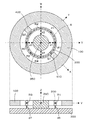
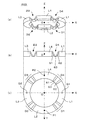
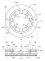
斜視図(a)に示す構造をもった検出リング(600)を用意する。この検出リング(600)は、側面図(b)に示すように、XY平面上にZ軸が中心軸となるように配置され、下面図(c)に示すように、その平面形状は円形のリングをなす。検出リング(600)は、弾性変形する板バネからなる4組の検出部(D1〜D4)を、4組の円弧状連結部(L1〜L4)で連結した構造を有する。検出リング(600)の下方に支持基板を配置し、Y軸上に配置された固定点(P1,P2)を支持基板に固定する。検出対象となる力やモーメントを作用点(Q1,Q2)に作用させると、4組の検出部(D1〜D4)が弾性変形を生じる。各検出部(D1〜D4)の変位部(63)の底面にそれぞれ変位電極を形成し、支持基板の対向面に固定電極を形成して4組の容量素子を形成し、その静電容量値の変動量に基づく演算により、作用した力やモーメントを検出する。A detection ring (600) having a structure shown in the perspective view (a) is prepared. As shown in the side view (b), the detection ring (600) is arranged on the XY plane so that the Z axis is the central axis, and the planar shape is circular as shown in the bottom view (c). Make a ring. The detection ring (600) has a structure in which four sets of detection parts (D1 to D4) made of elastically deformed leaf springs are connected by four sets of arcuate connection parts (L1 to L4). A support substrate is arranged below the detection ring (600), and fixing points (P1, P2) arranged on the Y axis are fixed to the support substrate. When a force or moment to be detected is applied to the action points (Q1, Q2), the four detection units (D1 to D4) are elastically deformed. Displacement electrodes are respectively formed on the bottom surfaces of the displacement portions (63) of the detection portions (D1 to D4), and fixed electrodes are formed on the opposing surface of the support substrate to form four sets of capacitance elements. The applied force or moment is detected by calculation based on the amount of fluctuation.
Description
本発明は、本発明は、力覚センサに関し、特に、三次元直交座標系における各座標軸方向の力および各座標軸まわりのモーメントを検出するのに適したセンサに関する。 The present invention relates to a force sensor, and more particularly to a sensor suitable for detecting a force in each coordinate axis direction and a moment around each coordinate axis in a three-dimensional orthogonal coordinate system.
ロボットや産業機械の動作制御を行うために、種々のタイプの力覚センサが利用されている。また、電子機器の入力装置のマン・マシンインターフェイスとしても、小型の力覚センサが組み込まれている。このような用途に用いる力覚センサには、小型化およびコストダウンを図るために、できるだけ構造を単純にするとともに、三次元空間内での各座標軸に関する力をそれぞれ独立して検出できるようにすることが要求される。 Various types of force sensors are used to control the operation of robots and industrial machines. A small force sensor is also incorporated as a man-machine interface of an input device of an electronic device. In order to reduce the size and reduce the cost, the force sensor used for such an application has a simple structure as much as possible, and can detect the force relating to each coordinate axis in a three-dimensional space independently. Is required.
現在、一般に利用されている多軸力覚センサは、機械的構造部に作用した力の特定の方向成分を、特定の部分に生じた変位として検出するタイプのものと、特定の部分に生じた機械的な歪みとして検出するタイプのものに分類される。前者の変位検出タイプの代表格は、静電容量素子式の力覚センサであり、一対の電極により容量素子を構成しておき、作用した力によって一方の電極に生じた変位を、容量素子の静電容量値に基づいて検出するものである。たとえば、下記の特許文献1(その英語版が特許文献2)や特許文献3(その英語版が特許文献4)には、この静電容量式の多軸力覚センサが開示されている。 Currently, the multi-axis force sensor that is generally used is a type that detects a specific direction component of a force acting on a mechanical structure part as a displacement generated in a specific part and a specific part. It is classified as a type to detect as mechanical strain. A typical example of the former displacement detection type is a capacitive element type force sensor, in which a capacitive element is configured by a pair of electrodes, and the displacement generated in one electrode by the applied force is detected by the capacitive element. The detection is based on the capacitance value. For example, Patent Document 1 (the English version of which is Patent Document 2) and Patent Document 3 (the English version of which is Patent Document 4) disclose this capacitance-type multi-axis force sensor.
一方、後者の機械的な歪み検出タイプの代表格は、歪みゲージ式の力覚センサであり、作用した力によって生じた機械的な歪みを、ストレインゲージなどの電気抵抗の変化として検出するものである。たとえば、下記の特許文献5(その英語版が特許文献6)には、この歪みゲージ式の多軸力覚センサが開示されている。 On the other hand, a representative of the latter type of mechanical strain detection is a strain gauge type force sensor that detects mechanical strain caused by the applied force as a change in electrical resistance such as a strain gauge. is there. For example, the following Patent Document 5 (the English version of which is Patent Document 6) discloses this strain gauge type multi-axis force sensor.
しかしながら、上述した各特許文献に開示されている多軸力覚センサは、いずれも機械的構造部の厚みが大きくならざるを得ず、装置全体を薄型化することが困難である。その一方で、ロボット、産業機械、電子機器用入力装置などの分野では、より薄型の力覚センサの登場が望まれている。そこで、特許文献7には、力の作用により環状部材の形状を変形させ、この変形に起因して生じる各部の変位を容量素子によって検出する力覚センサが提案されている。この特許文献7に開示されている力覚センサ(本願では、先願力覚センサと呼ぶ)は、構造を単純化して薄型化するのに適した構造を有している。 However, any of the multi-axis force sensors disclosed in the above-mentioned patent documents has to have a large mechanical structure, and it is difficult to reduce the thickness of the entire device. On the other hand, in the fields of robots, industrial machines, input devices for electronic devices, etc., the appearance of thinner force sensors is desired. Therefore, Patent Document 7 proposes a force sensor that deforms the shape of the annular member by the action of a force and detects displacement of each part caused by the deformation by a capacitive element. The force sensor disclosed in Patent Document 7 (referred to as a prior application force sensor in the present application) has a structure suitable for simplifying the structure and reducing the thickness.
しかしながら、上述した先願力覚センサでは、環状部材の様々な変形態様を検出するために、様々な箇所に容量素子を配置する必要があるため、容量素子を構成する電極構成が複雑にならざるを得ない。しかも、容量素子を構成する一対の電極の相対位置は、検出精度に影響を与える重大な要因になるため、個々の電極の位置調整に多大な作業負担が必要になる。特に、複数の容量素子を対称性をもたせて配置し、これらを用いて差分検出を行う場合、個々の容量素子ごとに対向電極が平行になるようにするとともに、複数の容量素子についての電極間隔が互いに等しくなるような調整が必要になる。このため、商業的に利用する上では、生産効率が低下し、コストが高騰するという問題がある。 However, in the above-described prior application force sensor, since it is necessary to arrange capacitive elements at various locations in order to detect various deformation modes of the annular member, the configuration of the electrodes constituting the capacitive elements does not have to be complicated. I do not get. In addition, since the relative position of the pair of electrodes constituting the capacitive element becomes a significant factor that affects the detection accuracy, a great work load is required for adjusting the position of each electrode. In particular, when a plurality of capacitive elements are arranged with symmetry and difference detection is performed using them, the counter electrode is made parallel to each capacitive element, and the electrode spacing for the multiple capacitive elements It is necessary to make adjustments so that they are equal to each other. For this reason, when it uses commercially, there exists a problem that production efficiency falls and cost rises.
そこで本発明は、構造が単純で、しかも検出素子の配置の自由度を向上させることにより、高い生産効率が実現可能な力覚センサを提供することを目的とする。 Accordingly, an object of the present invention is to provide a force sensor that has a simple structure and can realize high production efficiency by improving the degree of freedom of arrangement of detection elements.
(1) 本発明の第1の態様は、XYZ三次元直交座標系における各座標軸方向の力および各座標軸まわりのモーメントのうち、少なくとも1軸に関する力もしくはモーメントを検出する力覚センサにおいて、
検出対象となる力もしくはモーメントの作用を受ける受力体と、
所定の基本環状路に沿って伸びる環状構造を有し、基本環状路上に定義された検出点に位置する検出部と、この検出部の両側に位置する連結部と、を有する検出リングと、
検出リングを支持する支持体と、
受力体を、検出リングの所定の作用点の位置に接続する接続部材と、
検出リングの所定の固定点の位置を、支持体に固定する固定部材と、
検出部に生じた弾性変形を検出する検出素子と、
検出素子の検出結果に基づいて、受力体および支持体の一方に負荷がかかった状態において他方に作用した力もしくはモーメントを示す電気信号を出力する検出回路と、
を設け、
作用点および固定点は、連結部の互いに異なる位置に配置されており、
検出部は、作用点と固定点との間に力が作用したときに、作用した力に基づいて少なくとも一部が弾性変形を生じる構造を有するようにしたものである。
(1) A first aspect of the present invention is a force sensor that detects a force or a moment related to at least one axis among a force in each coordinate axis direction and a moment around each coordinate axis in an XYZ three-dimensional orthogonal coordinate system.
A force receiving body that receives the action of a force or moment to be detected;
A detection ring having an annular structure extending along a predetermined basic annular path, having a detection unit located at a detection point defined on the basic annular path, and a coupling part positioned on both sides of the detection unit;
A support for supporting the detection ring;
A connection member for connecting the force receiving body to a position of a predetermined operating point of the detection ring;
A fixing member for fixing the position of the predetermined fixing point of the detection ring to the support;
A detection element for detecting elastic deformation generated in the detection unit;
A detection circuit that outputs an electrical signal indicating a force or moment acting on one of the force receiving member and the support in a state where a load is applied to the other based on the detection result of the detection element;
Provided,
The action point and the fixed point are arranged at different positions of the connecting part,
The detection unit has a structure in which, when a force is applied between the action point and the fixed point, at least a part thereof is elastically deformed based on the applied force.
(2) 本発明の第2の態様は、上述した第1の態様に係る力覚センサにおいて、
検出素子が、検出部の所定位置に固定された変位電極と、支持体もしくは受力体の変位電極に対向する位置に固定された固定電極と、を有する容量素子によって構成され、
変位電極は、検出部に生じた弾性変形に基づいて固定電極に対して変位を生じる位置に配置されており、
検出回路が、容量素子の静電容量値の変動に基づいて、作用した力もしくはモーメントを示す電気信号を出力するようにしたものである。
(2) According to a second aspect of the present invention, in the force sensor according to the first aspect described above,
The detection element is constituted by a capacitive element having a displacement electrode fixed at a predetermined position of the detection unit and a fixed electrode fixed at a position facing the displacement electrode of the support or power receiving body,
The displacement electrode is disposed at a position that causes displacement with respect to the fixed electrode based on elastic deformation generated in the detection unit,
The detection circuit outputs an electric signal indicating the applied force or moment based on the fluctuation of the capacitance value of the capacitive element.
(3) 本発明の第3の態様は、上述した第2の態様に係る力覚センサにおいて、
XY平面を水平面にとり、Z軸を垂直上方に向かう軸としたときに、
検出リングが、Z軸を中心軸としてXY平面に位置する基本環状路に沿って伸びる環状構造を有し、
支持体が、検出リングの下方に所定間隔をおいて配置された支持基板によって構成され、
変位電極が検出部の下面に固定され、固定電極が支持基板の上面に固定されているようにしたものである。
(3) A third aspect of the present invention is the force sensor according to the second aspect described above,
When the XY plane is a horizontal plane and the Z axis is an axis that goes vertically upward,
The detection ring has an annular structure extending along a basic annular path located in the XY plane with the Z axis as a central axis;
The support is configured by a support substrate disposed at a predetermined interval below the detection ring,
The displacement electrode is fixed to the lower surface of the detection unit, and the fixed electrode is fixed to the upper surface of the support substrate.
(4) 本発明の第4の態様は、上述した第3の態様に係る力覚センサにおいて、
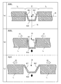
検出部が、検出対象となる力もしくはモーメントの作用により弾性変形を生じる第1の変形部と、検出対象となる力もしくはモーメントの作用により弾性変形を生じる第2の変形部と、第1の変形部および第2の変形部の弾性変形により変位を生じる変位部と、を有し、
第1の変形部の外側端はこれに隣接する連結部に接続され、第1の変形部の内側端は変位部に接続され、第2の変形部の外側端はこれに隣接する連結部に接続され、第2の変形部の内側端は変位部に接続され、
変位電極は、変位部の支持基板に対向する位置に固定されているようにしたものである。
(4) According to a fourth aspect of the present invention, in the force sensor according to the third aspect described above,
The detection unit includes a first deformation unit that generates elastic deformation by the action of a force or moment to be detected, a second deformation unit that generates elastic deformation by the action of a force or moment to be detected, and a first deformation A displacement part that produces displacement by elastic deformation of the part and the second deformation part,
The outer end of the first deformable portion is connected to a connecting portion adjacent thereto, the inner end of the first deformable portion is connected to the displacement portion, and the outer end of the second deformable portion is connected to the connecting portion adjacent thereto. Connected, the inner end of the second deformation part is connected to the displacement part,
The displacement electrode is fixed at a position facing the support substrate of the displacement portion.
(5) 本発明の第5の態様は、上述した第4の態様に係る力覚センサにおいて、
基本環状路上に複数n個(n≧2)の検出点が定義され、各検出点にそれぞれ検出部が位置しており、検出リングが、n個の検出部とn個の連結部とを、基本環状路に沿って交互に配置することにより構成されているようにしたものである。
(5) According to a fifth aspect of the present invention, in the force sensor according to the fourth aspect described above,
A plurality of n (n ≧ 2) detection points are defined on the basic circular path, the detection unit is located at each detection point, and the detection ring includes n detection units and n connection units. It is configured to be arranged alternately along the basic annular path.
(6) 本発明の第6の態様は、上述した第5の態様に係る力覚センサにおいて、
基本環状路上に偶数n個(n≧2)の検出点が定義され、各検出点にそれぞれ検出部が位置しており、検出リングが、n個の検出部とn個の連結部とを、基本環状路に沿って交互に配置することにより構成されているようにしたものである。
(6) According to a sixth aspect of the present invention, in the force sensor according to the fifth aspect described above,
An even number of n detection points (n ≧ 2) are defined on the basic circular path, the detection unit is located at each detection point, and the detection ring includes n detection units and n connection units. It is configured to be arranged alternately along the basic annular path.
(7) 本発明の第7の態様は、上述した第6の態様に係る力覚センサにおいて、
偶数n個の連結部に対して、基本環状路に沿って順に番号を付与したときに、作用点が奇数番目の連結部に配置され、固定点が偶数番目の連結部に配置されているようにしたものである。
(7) A seventh aspect of the present invention is the force sensor according to the sixth aspect described above,
When numbers are assigned in order along the basic circular path to the even number n of the connecting parts, the action points are arranged at the odd numbered connecting parts, and the fixed points are arranged at the even numbered connecting parts. It is a thing.
(8) 本発明の第8の態様は、上述した第7の態様に係る力覚センサにおいて、
n=2に設定することにより、基本環状路に沿って、第1の連結部、第1の検出部、第2の連結部、第2の検出部を、この順序で配置することにより検出リングが構成されており、作用点が第1の連結部に配置され、固定点が第2の連結部に配置されているようにしたものである。
(8) The eighth aspect of the present invention is the force sensor according to the seventh aspect described above,
By setting n = 2, the detection ring is arranged by arranging the first connecting portion, the first detecting portion, the second connecting portion, and the second detecting portion in this order along the basic circular path. In which the action point is arranged at the first connecting portion and the fixed point is arranged at the second connecting portion.
(9) 本発明の第9の態様は、上述した第7の態様に係る力覚センサにおいて、
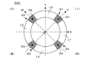
n=4に設定することにより、基本環状路に沿って、第1の連結部、第1の検出部、第2の連結部、第2の検出部、第3の連結部、第3の検出部、第4の連結部、第4の検出部を、この順序で配置することにより検出リングが構成されており、第1の作用点が第1の連結部に配置され、第1の固定点が第2の連結部に配置され、第2の作用点が第3の連結部に配置され、第2の固定点が第4の連結部に配置され、
接続部材が、検出リングの第1の作用点の位置を受力体に接続する第1の接続部材と、検出リングの第2の作用点の位置を受力体に接続する第2の接続部材とを有し、
固定部材が、検出リングの第1の固定点の位置を支持基板に固定する第1の固定部材と、検出リングの第2の固定点の位置を支持基板に固定する第2の固定部材とを有するようにしたものである。
(9) A ninth aspect of the present invention is the force sensor according to the seventh aspect described above,
By setting n = 4, the first connecting part, the first detecting part, the second connecting part, the second detecting part, the third connecting part, and the third detecting part along the basic circular path The detection ring is configured by arranging the part, the fourth connection part, and the fourth detection part in this order, the first action point is arranged in the first connection part, and the first fixed point Is arranged in the second coupling part, the second action point is arranged in the third coupling part, the second fixing point is arranged in the fourth coupling part,
The connection member connects the position of the first action point of the detection ring to the force receiving body, and the second connection member connects the position of the second action point of the detection ring to the force receiving body. And
A fixing member includes a first fixing member that fixes the position of the first fixing point of the detection ring to the support substrate, and a second fixing member that fixes the position of the second fixing point of the detection ring to the support substrate. It is what you have.
(10) 本発明の第10の態様は、上述した第9の態様に係る力覚センサにおいて、
第1の作用点が正のX軸上に配置され、第2の作用点が負のX軸上に配置され、第1の固定点が正のY軸上に配置され、第2の固定点が負のY軸上に配置されているようにしたものである。
(10) According to a tenth aspect of the present invention, in the force sensor according to the ninth aspect described above,
The first action point is located on the positive X axis, the second action point is located on the negative X axis, the first fixed point is located on the positive Y axis, and the second fixed point Are arranged on the negative Y-axis.
(11) 本発明の第11の態様は、上述した第10の態様に係る力覚センサにおいて、
XY平面において、原点Oを中心としてX軸を反時計まわりに45°回転させた座標軸としてV軸を定義し、原点Oを中心としてY軸を反時計まわりに45°回転させた座標軸としてW軸を定義した場合に、第1の検出点が正のV軸上、第2の検出点が正のW軸上、第3の検出点が負のV軸上、第4の検出点が負のW軸上に配置されているようにしたものである。
(11) An eleventh aspect of the present invention is the force sensor according to the tenth aspect described above,
In the XY plane, the V axis is defined as a coordinate axis obtained by rotating the X axis 45 degrees counterclockwise around the origin O, and the W axis is defined as a coordinate axis obtained by rotating the Y axis 45 degrees counterclockwise around the origin O. Is defined, the first detection point is on the positive V axis, the second detection point is on the positive W axis, the third detection point is on the negative V axis, and the fourth detection point is negative. It is arranged on the W axis.
(12) 本発明の第12の態様は、上述した第11の態様に係る力覚センサにおいて、
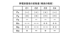
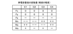
個々の検出部には、基本環状路に沿って圧縮応力が作用したときと伸張応力が作用したときとでは、静電容量値の増減が逆転する容量素子が形成されており、
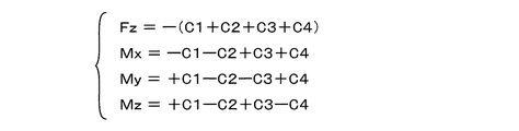
第1の検出点に位置する第1の検出部に固定された変位電極を有する第1の容量素子の静電容量値をC1、第2の検出点に位置する第2の検出部に固定された変位電極を有する第2の容量素子の静電容量値をC2、第3の検出点に位置する第3の検出部に固定された変位電極を有する第3の容量素子の静電容量値をC3、第4の検出点に位置する第4の検出部に固定された変位電極を有する第4の容量素子の静電容量値をC4、としたときに、
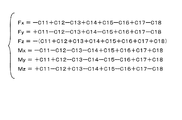
検出回路が、
Fz=−(C1+C2+C3+C4)
Mx=−C1−C2+C3+C4
My=+C1−C2−C3+C4
Mz=+C1−C2+C3−C4
なる演算式に基づく演算を行うことにより、Z軸方向に作用した力Fz、X軸まわりに作用したモーメントMx、Y軸まわりに作用したモーメントMy、およびZ軸まわりに作用したモーメントMzを示す電気信号を出力するようにしたものである。
(12) According to a twelfth aspect of the present invention, in the force sensor according to the eleventh aspect described above,
In each detection unit, a capacitive element is formed in which the increase or decrease in the capacitance value is reversed between when the compressive stress is applied along the basic annular path and when the tensile stress is applied.
The capacitance value of the first capacitive element having the displacement electrode fixed to the first detection unit located at the first detection point is fixed to C1, and the second detection unit located at the second detection point is fixed. The capacitance value of the second capacitance element having the displacement electrode is C2, and the capacitance value of the third capacitance element having the displacement electrode fixed to the third detection unit located at the third detection point is C2. C3, when the capacitance value of the fourth capacitive element having the displacement electrode fixed to the fourth detection unit located at the fourth detection point is C4,
The detection circuit
Fz =-(C1 + C2 + C3 + C4)
Mx = −C1-C2 + C3 + C4
My = + C1-C2-C3 + C4
Mz = + C1-C2 + C3-C4
Electricity indicating the force Fz acting in the Z-axis direction, the moment Mx acting around the X-axis, the moment My acting around the Y-axis, and the moment Mz acting around the Z-axis by performing the calculation based on the following equation: A signal is output.
(13) 本発明の第13の態様は、上述した第7の態様に係る力覚センサにおいて、
n=8に設定することにより、基本環状路に沿って、第1の連結部、第1の検出部、第2の連結部、第2の検出部、第3の連結部、第3の検出部、第4の連結部、第4の検出部、第5の連結部、第5の検出部、第6の連結部、第6の検出部、第7の連結部、第7の検出部、第8の連結部、第8の検出部を、この順序で配置することにより検出リングが構成されており、
第1の作用点が第1の連結部に配置され、第1の固定点が第2の連結部に配置され、第2の作用点が第3の連結部に配置され、第2の固定点が第4の連結部に配置され、第3の作用点が第5の連結部に配置され、第3の固定点が第6の連結部に配置され、第4の作用点が第7の連結部に配置され、第4の固定点が第8の連結部に配置され、
接続部材が、検出リングの第1の作用点の位置を受力体に接続する第1の接続部材と、検出リングの第2の作用点の位置を受力体に接続する第2の接続部材と、検出リングの第3の作用点の位置を受力体に接続する第3の接続部材と、検出リングの第4の作用点の位置を受力体に接続する第4の接続部材と、を有し、
固定部材が、検出リングの第1の固定点の位置を支持基板に固定する第1の固定部材と、検出リングの第2の固定点の位置を支持基板に固定する第2の固定部材と、検出リングの第3の固定点の位置を支持基板に固定する第3の固定部材と、検出リングの第4の固定点の位置を支持基板に固定する第4の固定部材と、を有するようにしたものである。
(13) The thirteenth aspect of the present invention is the force sensor according to the seventh aspect described above,
By setting n = 8, the first connecting part, the first detecting part, the second connecting part, the second detecting part, the third connecting part, and the third detecting part along the basic circular path Part, fourth connecting part, fourth detecting part, fifth connecting part, fifth detecting part, sixth connecting part, sixth detecting part, seventh connecting part, seventh detecting part, A detection ring is configured by arranging the eighth connecting portion and the eighth detecting portion in this order.
The first action point is arranged at the first connecting part, the first fixing point is arranged at the second connecting part, the second action point is arranged at the third connecting part, and the second fixing point Is arranged at the fourth connecting part, the third action point is arranged at the fifth connecting part, the third fixing point is arranged at the sixth connecting part, and the fourth action point is the seventh connecting part. The fourth fixed point is disposed in the eighth connecting portion,
The connection member connects the position of the first action point of the detection ring to the force receiving body, and the second connection member connects the position of the second action point of the detection ring to the force receiving body. A third connection member that connects the position of the third action point of the detection ring to the force receiving body, a fourth connection member that connects the position of the fourth action point of the detection ring to the force reception body, Have
A fixing member that fixes the position of the first fixing point of the detection ring to the support substrate; a second fixing member that fixes the position of the second fixing point of the detection ring to the support substrate; A third fixing member that fixes the position of the third fixing point of the detection ring to the support substrate; and a fourth fixing member that fixes the position of the fourth fixing point of the detection ring to the support substrate. It is what.
(14) 本発明の第14の態様は、上述した第13の態様に係る力覚センサにおいて、
XY平面において、原点Oを中心としてX軸を反時計まわりに45°回転させた座標軸としてV軸を定義し、原点Oを中心としてY軸を反時計まわりに45°回転させた座標軸としてW軸を定義した場合に、
第1の作用点が正のX軸上、第2の作用点が正のY軸上、第3の作用点が負のX軸上、第4の作用点が負のY軸上、第1の固定点が正のV軸上、第2の固定点が正のW軸上、第3の固定点が負のV軸上、第4の固定点が負のW軸上に配置されているようにしたものである。
(14) According to a fourteenth aspect of the present invention, in the force sensor according to the thirteenth aspect described above,
In the XY plane, the V axis is defined as a coordinate axis obtained by rotating the X axis 45 degrees counterclockwise around the origin O, and the W axis is defined as a coordinate axis obtained by rotating the Y axis 45 degrees counterclockwise around the origin O. If you define
The first action point is on the positive X axis, the second action point is on the positive Y axis, the third action point is on the negative X axis, the fourth action point is on the negative Y axis, Are fixed on the positive V-axis, the second fixed point is on the positive W-axis, the third fixed point is on the negative V-axis, and the fourth fixed point is on the negative W-axis. It is what I did.
(15) 本発明の第15の態様は、上述した第14の態様に係る力覚センサにおいて、
XY平面において、原点Oを起点として、X軸正方向に対して反時計まわりに角度θをなす方位ベクトルVec(θ)を定義したときに、第i番目(但し、1≦i≦8)の検出点が、方位ベクトルVec(π/8+(i−1)・π/4)と基本環状路との交点位置に配置されているようにしたものである。
(15) According to a fifteenth aspect of the present invention, in the force sensor according to the fourteenth aspect described above,
In the XY plane, when an azimuth vector Vec (θ) that defines an angle θ counterclockwise with respect to the positive direction of the X axis starting from the origin O is defined as the i-th (where 1 ≦ i ≦ 8) The detection point is arranged at the intersection of the direction vector Vec (π / 8 + (i−1) · π / 4) and the basic circular path.
(16) 本発明の第16の態様は、上述した第15の態様に係る力覚センサにおいて、
個々の検出部には、基本環状路に沿って圧縮応力が作用したときと伸張応力が作用したときとでは、静電容量値の増減が逆転する容量素子が形成されており、
第i番目の検出点に位置する第i番目の検出部に固定された変位電極を有する第i番目の容量素子の静電容量値をC1iとしたときに、
検出回路が、
X軸方向に作用した力Fxに関しては、
Fx=−C11+C12−C13+C14+C15−C16+C17−C18
もしくは、Fx=−C11+C12+C17−C18
もしくは、Fx=+C12−C13−C16+C17
なる演算式、
Y軸方向に作用した力Fyに関しては、
Fy=+C11−C12−C13+C14−C15+C16+C17−C18
もしくは、Fy=+C11−C12−C13+C14
もしくは、Fy=−C15+C16+C17−C18
なる演算式、
Z軸方向に作用した力Fzに関しては、
Fz=−(C11+C12+C13+C14+C15+C16+C17+C18)
もしくは、Fz=−(C11+C14+C15+C18)
もしくは、Fz=−(C12+C13+C16+C17)
なる演算式、
X軸まわりに作用したモーメントMxに関しては、
Mx=−C11−C12−C13−C14+C15+C16+C17+C18
もしくは、Mx=−C11−C12+C17+C18
もしくは、Mx=−C13−C14+C15+C16
なる演算式、
Y軸まわりに作用したモーメントMyに関しては、
My=+C11+C12−C13−C14−C15−C16+C17+C18
もしくは、My=+C11+C12−C13−C14
もしくは、My=−C15−C16+C17+C18
なる演算式、
Z軸まわりに作用したモーメントMzに関しては、
Mz=+C11−C12+C13−C14+C15−C16+C17−C18
もしくは、Mz=+C11−C12+C15−C16
もしくは、Mz=+C13−C14+C17−C18
もしくは、Mz=+C11−C14+C15−C18
なる演算式、
に基づく演算を行うことにより、力Fx、力Fy、力Fz、モーメントMx、モーメントMy、およびモーメントMzを示す電気信号を出力するようにしたものである。
(16) According to a sixteenth aspect of the present invention, in the force sensor according to the fifteenth aspect described above,
In each detection unit, a capacitive element is formed in which the increase or decrease in the capacitance value is reversed between when the compressive stress is applied along the basic annular path and when the tensile stress is applied.
When the capacitance value of the i-th capacitive element having the displacement electrode fixed to the i-th detection unit located at the i-th detection point is C1i,
The detection circuit
Regarding the force Fx acting in the X-axis direction,
Fx = −C11 + C12−C13 + C14 + C15−C16 + C17−C18
Or, Fx = −C11 + C12 + C17−C18
Or, Fx = + C12−C13−C16 + C17
The following formula
Regarding the force Fy acting in the Y-axis direction,
Fy = + C11-C12-C13 + C14-C15 + C16 + C17-C18
Or, Fy = + C11−C12−C13 + C14
Or, Fy = −C15 + C16 + C17−C18
The following formula
Regarding the force Fz acting in the Z-axis direction,
Fz = − (C11 + C12 + C13 + C14 + C15 + C16 + C17 + C18)
Or, Fz = − (C11 + C14 + C15 + C18)
Or, Fz = − (C12 + C13 + C16 + C17)
The following formula
Regarding the moment Mx acting around the X axis,
Mx = −C11−C12−C13−C14 + C15 + C16 + C17 + C18
Or, Mx = −C11−C12 + C17 + C18
Or, Mx = −C13−C14 + C15 + C16
The following formula
Regarding the moment My acting around the Y axis,
My = + C11 + C12-C13-C14-C15-C16 + C17 + C18
Or, My = + C11 + C12-C13-C14
Or, My = −C15−C16 + C17 + C18
The following formula
Regarding the moment Mz acting around the Z axis,
Mz = + C11-C12 + C13-C14 + C15-C16 + C17-C18
Or, Mz = + C11−C12 + C15−C16
Or, Mz = + C13−C14 + C17−C18
Or, Mz = + C11−C14 + C15−C18
The following formula
By performing the calculation based on the above, electric signals indicating the force Fx, force Fy, force Fz, moment Mx, moment My, and moment Mz are output.
(17) 本発明の第17の態様は、上述した第6の態様に係る力覚センサにおいて、
偶数n個の連結部に対して、基本環状路に沿って順に番号を付与したときに、作用点および固定点が、いずれも奇数番目の連結部に、かつ、作用点と固定点とが基本環状路に沿って交互になるように配置されているようにしたものである。
(17) According to a seventeenth aspect of the present invention, in the force sensor according to the sixth aspect described above,
When numbers are assigned in order along the basic circular path to even number n of the connecting parts, the action point and the fixed point are both odd-numbered connection parts, and the action point and the fixed point are basic. It is arranged so as to alternate along the circular path.
(18) 本発明の第18の態様は、上述した第17の態様に係る力覚センサにおいて、
n=8に設定することにより、基本環状路に沿って、第1の連結部、第1の検出部、第2の連結部、第2の検出部、第3の連結部、第3の検出部、第4の連結部、第4の検出部、第5の連結部、第5の検出部、第6の連結部、第6の検出部、第7の連結部、第7の検出部、第8の連結部、第8の検出部を、この順序で配置することにより検出リングが構成されており、
第1の固定点が第1の連結部に配置され、第1の作用点が第3の連結部に配置され、第2の固定点が第5の連結部に配置され、第2の作用点が第7の連結部に配置され、
接続部材が、検出リングの第1の作用点の位置を受力体に接続する第1の接続部材と、検出リングの第2の作用点の位置を受力体に接続する第2の接続部材と、を有し、
固定部材が、検出リングの第1の固定点の位置を支持基板に固定する第1の固定部材と、検出リングの第2の固定点の位置を支持基板に固定する第2の固定部材と、を有するようにしたものである。
(18) According to an eighteenth aspect of the present invention, in the force sensor according to the seventeenth aspect described above,
By setting n = 8, the first connecting part, the first detecting part, the second connecting part, the second detecting part, the third connecting part, and the third detecting part along the basic circular path Part, fourth connecting part, fourth detecting part, fifth connecting part, fifth detecting part, sixth connecting part, sixth detecting part, seventh connecting part, seventh detecting part, A detection ring is configured by arranging the eighth connecting portion and the eighth detecting portion in this order.
The first fixed point is arranged at the first connecting part, the first action point is arranged at the third connecting part, the second fixed point is arranged at the fifth connecting part, and the second action point is arranged. Is disposed in the seventh connecting portion,
The connection member connects the position of the first action point of the detection ring to the force receiving body, and the second connection member connects the position of the second action point of the detection ring to the force receiving body. And having
A fixing member that fixes the position of the first fixing point of the detection ring to the support substrate; a second fixing member that fixes the position of the second fixing point of the detection ring to the support substrate; It is made to have.
(19) 本発明の第19の態様は、上述した第18の態様に係る力覚センサにおいて、
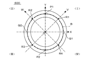
第1の固定点が正のX軸上に配置され、第2の固定点が負のX軸上に配置され、第1の作用点が正のY軸上に配置され、第2の作用点が負のY軸上に配置されているようにしたものである。
(19) According to a nineteenth aspect of the present invention, in the force sensor according to the eighteenth aspect described above,
The first fixed point is located on the positive X axis, the second fixed point is located on the negative X axis, the first action point is located on the positive Y axis, and the second action point Are arranged on the negative Y-axis.
(20) 本発明の第20の態様は、上述した第19の態様に係る力覚センサにおいて、
検出リングが、原点Oを中心としてXY平面に配置された正方形の環状構造体であり、Y軸に平行な方向に伸び正のX軸と交差する第1の辺と、X軸に平行な方向に伸び正のY軸と交差する第2の辺と、Y軸に平行な方向に伸び負のX軸と交差する第3の辺と、X軸に平行な方向に伸び負のY軸と交差する第4の辺と、を有し、
第1の検出点が、第1の辺の正のY座標をもつ位置に配置され、第2の検出点が、第2の辺の正のX座標をもつ位置に配置され、第3の検出点が、第2の辺の負のX座標をもつ位置に配置され、第4の検出点が、第3の辺の正のY座標をもつ位置に配置され、第5の検出点が、第3の辺の負のY座標をもつ位置に配置され、第6の検出点が、第4の辺の負のX座標をもつ位置に配置され、第7の検出点が、第4の辺の正のX座標をもつ位置に配置され、第8の検出点が、第1の辺の負のY座標をもつ位置に配置されているようにしたものである。
(20) According to a twentieth aspect of the present invention, in the force sensor according to the nineteenth aspect described above,
The detection ring is a square annular structure disposed on the XY plane with the origin O as the center, the first side extending in a direction parallel to the Y axis and intersecting the positive X axis, and a direction parallel to the X axis A second side that crosses the positive Y axis, a third side that extends in a direction parallel to the Y axis, and a negative side that extends in a direction parallel to the X axis. And a fourth side to
The first detection point is arranged at a position having a positive Y coordinate of the first side, the second detection point is arranged at a position having a positive X coordinate of the second side, and the third detection The point is placed at a position having a negative X coordinate of the second side, the fourth detection point is placed at a position having a positive Y coordinate of the third side, and the fifth detection point is 3 is arranged at a position having a negative Y coordinate, the sixth detection point is arranged at a position having a negative X coordinate of the fourth side, and the seventh detection point is arranged at the position of the fourth side. It is arranged at a position having a positive X coordinate, and the eighth detection point is arranged at a position having a negative Y coordinate of the first side.
(21) 本発明の第21の態様は、上述した第20の態様に係る力覚センサにおいて、
個々の検出部には、基本環状路に沿って圧縮応力が作用したときと伸張応力が作用したときとでは、静電容量値の増減が逆転する容量素子が形成されており、
第i番目の検出点に位置する第i番目の検出部に固定された変位電極を有する第i番目の容量素子の静電容量値をC1iとしたときに、
検出回路が、
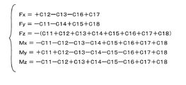
X軸方向に作用した力Fxに関しては、
Fx=+C12−C13−C16+C17
なる演算式、
Y軸方向に作用した力Fyに関しては、
Fy=−C11−C14+C15+C18
なる演算式、
Z軸方向に作用した力Fzに関しては、
Fz=−(C11+C12+C13+C14+C15+C16+C17+C18)
もしくは、Fz=−(C11+C13+C15+C17)
もしくは、Fz=−(C12+C14+C16+C18)
なる演算式、
X軸まわりに作用したモーメントMxに関しては、
Mx=−C11−C12−C13−C14+C15+C16+C17+C18
もしくは、Mx=−C12−C13+C16+C17
なる演算式、
Y軸まわりに作用したモーメントMyに関しては、
My=+C11+C12−C13−C14−C15−C16+C17+C18
もしくは、My=+C11−C14−C15+C18
なる演算式、
Z軸まわりに作用したモーメントMzに関しては、
Mz=−C11−C12+C13+C14−C15−C16+C17+C18
もしくは、Mz=−C11+C13−C15+C17
もしくは、Mz=−C12+C14−C16+C18
なる演算式、
に基づく演算を行うことにより、力Fx、力Fy、力Fz、モーメントMx、モーメントMy、およびモーメントMzを示す電気信号を出力するようにしたものである。
(21) According to a twenty-first aspect of the present invention, in the force sensor according to the twentieth aspect described above,
In each detection unit, a capacitive element is formed in which the increase or decrease in the capacitance value is reversed between when the compressive stress is applied along the basic annular path and when the tensile stress is applied.
When the capacitance value of the i-th capacitive element having the displacement electrode fixed to the i-th detection unit located at the i-th detection point is C1i,
The detection circuit
Regarding the force Fx acting in the X-axis direction,
Fx = + C12-C13-C16 + C17
The following formula
Regarding the force Fy acting in the Y-axis direction,
Fy = −C11−C14 + C15 + C18
The following formula
Regarding the force Fz acting in the Z-axis direction,
Fz = − (C11 + C12 + C13 + C14 + C15 + C16 + C17 + C18)
Or, Fz = − (C11 + C13 + C15 + C17)
Or, Fz = − (C12 + C14 + C16 + C18)
The following formula
Regarding the moment Mx acting around the X axis,
Mx = −C11−C12−C13−C14 + C15 + C16 + C17 + C18
Or, Mx = −C12−C13 + C16 + C17
The following formula
Regarding the moment My acting around the Y axis,
My = + C11 + C12-C13-C14-C15-C16 + C17 + C18
Or, My = + C11−C14−C15 + C18
The following formula
Regarding the moment Mz acting around the Z axis,
Mz = −C11−C12 + C13 + C14−C15−C16 + C17 + C18
Or, Mz = −C11 + C13−C15 + C17
Or, Mz = −C12 + C14−C16 + C18
The following formula
By performing the calculation based on the above, electric signals indicating the force Fx, force Fy, force Fz, moment Mx, moment My, and moment Mz are output.
(22) 本発明の第22の態様は、上述した第19の態様に係る力覚センサにおいて、
検出リングが、原点Oを中心としてXY平面に配置された円形の環状構造体であり、
XY平面において、原点Oを起点として、X軸正方向に対して反時計まわりに角度θをなす方位ベクトルVec(θ)を定義したときに、第i番目(但し、1≦i≦8)の検出点が、方位ベクトルVec(π/8+(i−1)・π/4)と基本環状路との交点位置に配置されているようにしたものである。
(22) According to a twenty-second aspect of the present invention, in the force sensor according to the nineteenth aspect described above,
The detection ring is a circular annular structure disposed in the XY plane with the origin O as the center,
In the XY plane, when an azimuth vector Vec (θ) that defines an angle θ counterclockwise with respect to the positive direction of the X axis starting from the origin O is defined as the i-th (where 1 ≦ i ≦ 8) The detection point is arranged at the intersection of the direction vector Vec (π / 8 + (i−1) · π / 4) and the basic circular path.
(23) 本発明の第23の態様は、上述した第5〜第22の態様に係る力覚センサにおいて、
検出対象となる特定の軸についての力もしくはモーメントに関して、複数n個の検出部のうち、一部は第1属性の検出部として振る舞い、他の一部は第2属性の検出部として振る舞い、
第1属性の検出部を構成する第1属性変位部は、上記特定の軸についての正の成分が作用したときに支持基板に近づく方向に変位し、上記特定の軸についての負の成分が作用したときに支持基板から遠ざかる方向に変位し、
第2属性の検出部を構成する第2属性変位部は、上記特定の軸についての正の成分が作用したときに支持基板から遠ざかる方向に変位し、上記特定の軸についての負の成分が作用したときに支持基板に近づく方向に変位し、
第1属性変位部に固定された第1属性変位電極と、支持基板の第1属性変位電極に対向する位置に固定された第1属性固定電極と、によって第1属性容量素子が構成され、
第2属性変位部に固定された第2属性変位電極と、支持基板の第2属性変位電極に対向する位置に固定された第2属性固定電極と、によって第2属性容量素子が構成され、
検出回路が、第1属性容量素子の静電容量値と、第2属性容量素子の静電容量値と、の差に相当する電気信号を、検出対象となる力もしくはモーメントの上記特定の軸についての成分を示す電気信号として出力するようにしたものである。
(23) According to a twenty-third aspect of the present invention, in the force sensor according to the fifth to twenty-second aspects described above,
Regarding a force or moment about a specific axis to be detected, among a plurality of n detection units, some behave as first attribute detection units, and the other behave as second attribute detection units,
The first attribute displacement unit constituting the first attribute detection unit is displaced in a direction approaching the support substrate when a positive component about the specific axis acts, and a negative component about the specific axis acts. Is displaced in a direction away from the support substrate,
The second attribute displacement unit constituting the second attribute detection unit is displaced in a direction away from the support substrate when a positive component about the specific axis acts, and a negative component about the specific axis acts. When moving to the direction of approaching the support substrate,
A first attribute capacitive element is constituted by the first attribute displacement electrode fixed to the first attribute displacement portion and the first attribute fixed electrode fixed at a position facing the first attribute displacement electrode of the support substrate,
A second attribute capacitive element is configured by the second attribute displacement electrode fixed to the second attribute displacement portion and the second attribute fixed electrode fixed to a position facing the second attribute displacement electrode of the support substrate,
The detection circuit detects an electric signal corresponding to the difference between the capacitance value of the first attribute capacitance element and the capacitance value of the second attribute capacitance element with respect to the specific axis of the force or moment to be detected. It is made to output as an electric signal which shows these components.
(24) 本発明の第24の態様は、上述した第4〜第23の態様に係る力覚センサにおいて、
検出リングが、Z軸を中心軸として配置された板状部材の中央部に、貫通開口部を形成することにより得られる環状の部材に対して、部分的な材料除去加工を施すことにより得られた部材であり、この材料除去加工を施した部分によって検出部が構成されているようにしたものである。
(24) According to a twenty-fourth aspect of the present invention, in the force sensor according to the fourth to twenty-third aspects described above,
The detection ring is obtained by subjecting an annular member obtained by forming a through opening to the center of a plate-like member arranged with the Z axis as the central axis, and performing a partial material removal process. The detection part is comprised by the part which performed this material removal process.
(25) 本発明の第25の態様は、上述した第4〜第24の態様に係る力覚センサにおいて、
第1の変形部、第2の変形部、変位部を有する検出部が、一方の連結部端部と他方の連結部端部との間に配置されており、
第1の変形部は、可撓性を有する第1の板状片によって構成され、第2の変形部は、可撓性を有する第2の板状片によって構成され、変位部は、第3の板状片によって構成され、
第1の板状片の外側端は、一方の連結部端部に接続され、第1の板状片の内側端は、第3の板状片の一端に接続され、第2の板状片の外側端は、他方の連結部端部に接続され、第2の板状片の内側端は、第3の板状片の他端に接続されているようにしたものである。
(25) According to a twenty-fifth aspect of the present invention, in the force sensor according to the fourth to twenty-fourth aspects described above,
A detection unit having a first deformation unit, a second deformation unit, and a displacement unit is disposed between one connection unit end and the other connection unit end,
The first deformable portion is constituted by a flexible first plate-like piece, the second deformable portion is constituted by a flexible second plate-like piece, and the displacement portion is a third piece. Composed of plate-like pieces,
The outer end of the first plate-like piece is connected to one end of the connecting portion, the inner end of the first plate-like piece is connected to one end of the third plate-like piece, and the second plate-like piece. The outer end of the second plate is connected to the other end of the connecting portion, and the inner end of the second plate-like piece is connected to the other end of the third plate-like piece.
(26) 本発明の第26の態様は、上述した第25の態様に係る力覚センサにおいて、
力もしくはモーメントが作用していない状態において、第3の板状片の対向面と支持基板の対向面とが平行を維持するようにしたものである。
(26) According to a twenty-sixth aspect of the present invention, in the force sensor according to the twenty-fifth aspect described above,
In the state where no force or moment is applied, the opposing surface of the third plate-like piece and the opposing surface of the support substrate are kept parallel.
(27) 本発明の第27の態様は、上述した第26の態様に係る力覚センサにおいて、
検出点の位置にXY平面に直交する法線を立てたときに、当該検出点に位置する検出部を構成する第1の板状片および第2の板状片が、法線に対して傾斜しており、かつ、第1の板状片の傾斜方向と第2の板状片の傾斜方向とが逆向きとなっているようにしたものである。
(27) According to a twenty-seventh aspect of the present invention, in the force sensor according to the twenty-sixth aspect described above,
When a normal line perpendicular to the XY plane is set at the position of the detection point, the first plate-like piece and the second plate-like piece constituting the detection unit located at the detection point are inclined with respect to the normal line. In addition, the inclination direction of the first plate-like piece and the inclination direction of the second plate-like piece are opposite to each other.
(28) 本発明の第28の態様は、上述した第3〜第27の態様に係る力覚センサにおいて、
作用点、もしくは、座標系の原点Oと作用点とを結ぶ線に沿って作用点を移動させた移動点、を通りZ軸に平行な接続参照線を定義したときに、接続参照線もしくはその近傍に沿って、検出リングもしくは受力体の下面と支持基板の上面とを接続する補助接続部材を更に設けるようにしたものである。
(28) According to a twenty-eighth aspect of the present invention, in the force sensor according to the third to twenty-seventh aspects described above,
When a connection reference line is defined that is parallel to the Z axis and passes through the action point or a movement point that moves the action point along the line connecting the origin O and the action point of the coordinate system, An auxiliary connection member for connecting the lower surface of the detection ring or force receiving member and the upper surface of the support substrate is further provided along the vicinity.
(29) 本発明の第29の態様は、上述した第28の態様に係る力覚センサにおいて、
補助接続部材として、接続参照線に沿った方向に力が作用したときに比べて、接続参照線に直交する方向に力が作用したときの方が、弾性変形を生じ易い部材を用いるようにしたものである。
(29) According to a twenty-ninth aspect of the present invention, in the force sensor according to the twenty-eighth aspect described above,
As an auxiliary connection member, a member that is more likely to be elastically deformed when a force is applied in a direction perpendicular to the connection reference line than when a force is applied in a direction along the connection reference line is used. Is.
(30) 本発明の第30の態様は、上述した第28または第29の態様に係る力覚センサにおいて、
検出リングもしくは受力体の補助接続部材に対する接続部分、もしくは、支持基板の補助接続部材に対する接続部分、または、これら接続部分の双方を、ダイアフラム部によって構成し、力もしくはモーメントの作用に基づくダイアフラム部の変形によって補助接続部材が接続参照線に対して傾斜するようにしたものである。
(30) A thirtieth aspect of the present invention is the force sensor according to the twenty-eighth or twenty-ninth aspect described above,
The connection part of the detection ring or the receiving body to the auxiliary connection member, the connection part of the support substrate to the auxiliary connection member, or both of these connection parts are constituted by a diaphragm part, and the diaphragm part based on the action of force or moment The auxiliary connection member is inclined with respect to the connection reference line by the deformation of the above.
(31) 本発明の第31の態様は、上述した第2〜第30の態様に係る力覚センサにおいて、
力もしくはモーメントが作用した結果、固定電極に対して変位電極が平行移動した場合にも、容量素子を構成する一対の電極の実効対向面積が変化しないように、固定電極および変位電極のうちの一方の面積を他方の面積よりも大きく設定するようにしたものである。
(31) According to a thirty-first aspect of the present invention, in the force sensor according to the second to thirtieth aspects described above,
One of the fixed electrode and the displacement electrode so that the effective facing area of the pair of electrodes constituting the capacitive element does not change even when the displacement electrode moves in parallel with the fixed electrode as a result of the force or moment acting. Is set to be larger than the other area.
(32) 本発明の第32の態様は、上述した第2〜第31の態様に係る力覚センサにおいて、
検出リング、支持体、受力体が導電性材料により構成されており、変位電極が検出リングの表面に絶縁層を介して形成されており、固定電極が支持体もしくは受力体の表面に絶縁層を介して形成されているようにしたものである。
(32) According to a thirty-second aspect of the present invention, in the force sensor according to the second to thirty-first aspects described above,
The detection ring, support, and power receiving body are made of a conductive material, the displacement electrode is formed on the surface of the detection ring via an insulating layer, and the fixed electrode is insulated from the surface of the support or power receiving body. It is formed through layers.
(33) 本発明の第33の態様は、上述した第2〜第32の態様に係る力覚センサにおいて、
検出リング、支持体、受力体が導電性材料により構成されており、検出リングの表面の一部の領域によって変位電極を構成するか、もしくは、支持体もしくは受力体の表面の一部の領域によって固定電極を構成したものである。
(33) According to a thirty-third aspect of the present invention, in the force sensor according to the second to thirty-second aspects described above,
The detection ring, the support, and the power receiving body are made of a conductive material, and a displacement electrode is formed by a part of the surface of the detection ring, or a part of the surface of the support or the power receiving body. The fixed electrode is configured by the region.
(34) 本発明の第34の態様は、上述した第1の態様に係る力覚センサにおいて、
検出素子が、検出部の弾性変形を生じる位置に固定されたストレインゲージによって構成されており、
検出回路が、ストレインゲージの電気抵抗の変動に基づいて、作用した力もしくはモーメントを示す電気信号を出力するようにしたものである。
(34) According to a thirty-fourth aspect of the present invention, in the force sensor according to the first aspect described above,
The detection element is composed of a strain gauge fixed at a position where elastic detection of the detection unit occurs.
The detection circuit outputs an electric signal indicating the applied force or moment based on the fluctuation of the electric resistance of the strain gauge.
(35) 本発明の第35の態様は、上述した第34の態様に係る力覚センサにおいて、
検出部が、検出対象となる力もしくはモーメントの作用により弾性変形を生じる板状変形部を有し、板状変形部はその板面が基本環状路に対して傾斜するように配置されているようにしたものである。
(35) According to a thirty-fifth aspect of the present invention, in the force sensor according to the thirty-fourth aspect described above,
The detection part has a plate-like deformation part that generates elastic deformation by the action of a force or moment to be detected, and the plate-like deformation part seems to be arranged such that its plate surface is inclined with respect to the basic annular path It is a thing.
(36) 本発明の第36の態様は、上述した第35の態様に係る力覚センサにおいて、
検出素子が、板状変形部の連結部に対する接続端近傍の両面に配置されたストレインゲージによって構成されているようにしたものである。
(36) The thirty-sixth aspect of the present invention is the force sensor according to the thirty-fifth aspect described above,
The detection element is configured by strain gauges arranged on both surfaces in the vicinity of the connection end with respect to the connecting portion of the plate-shaped deformable portion.
(37) 本発明の第37の態様は、上述した第36の態様に係る力覚センサにおいて、
検出素子が、連結部に対する第1の接続端近傍の表側の面および裏側の面にそれぞれ配置された第1のストレインゲージおよび第2のストレインゲージと、連結部に対する第2の接続端近傍の表側の面および裏側の面にそれぞれ配置された第3のストレインゲージおよび第4のストレインゲージと、を有し、
検出回路が、第1のストレインゲージと第4のストレインゲージとを第1の対辺とし、第2のストレインゲージと第3のストレインゲージとを第2の対辺とするブリッジ回路のブリッジ電圧を検出するようにしたものである。
(37) A thirty-seventh aspect of the present invention is the force sensor according to the thirty-sixth aspect described above,
A first strain gauge and a second strain gauge arranged on the front side surface and the back side surface in the vicinity of the first connection end with respect to the connecting portion, respectively, and the front side in the vicinity of the second connection end with respect to the connecting portion; A third strain gauge and a fourth strain gauge disposed on the surface and the back surface, respectively,
The detection circuit detects a bridge voltage of a bridge circuit having the first strain gauge and the fourth strain gauge as the first opposite sides and the second strain gauge and the third strain gauge as the second opposite sides. It is what I did.
(38) 本発明の第38の態様は、上述した第1〜第19、第34〜第37の態様に係る力覚センサにおいて、
検出リングが、Z軸を中心軸としてXY平面に配置された円を基本環状路とする環状構造体であり、
支持体が、Z軸を中心軸としてZ軸負領域に配置された円形の板状構造体もしくは環状構造体であり、
受力体が、Z軸を中心軸としてZ軸正領域に配置された円形の板状構造体もしくは環状構造体、またはZ軸を中心軸としてXY平面に配置された円形の板状構造体もしくは環状構造体であるようにしたものである。
(38) According to a thirty-eighth aspect of the present invention, in the force sensor according to the first to nineteenth and thirty-fourth to thirty-seventh aspects described above,
The detection ring is an annular structure having a circle arranged in the XY plane with the Z axis as the central axis as a basic annular path,
The support is a circular plate-like structure or an annular structure disposed in the negative Z-axis region with the Z-axis as the central axis,
The force receiving body is a circular plate-like structure or annular structure arranged in the Z-axis positive region with the Z axis as the central axis, or a circular plate-like structure arranged in the XY plane with the Z axis as the central axis, or It is a ring structure.
(39) 本発明の第39の態様は、上述した第1〜第19、第34〜第37の態様に係る力覚センサにおいて、
検出リングが、Z軸を中心軸としてXY平面に配置された正方形を基本環状路とする環状構造体であり、
支持体が、Z軸を中心軸としてZ軸負領域に配置された正方形の板状構造体もしくは環状構造体であり、
受力体が、Z軸を中心軸としてZ軸正領域に配置された正方形の板状構造体もしくは環状構造体、またはZ軸を中心軸としてXY平面に配置された正方形の板状構造体もしくは環状構造体であるようにしたものである。
(39) According to a 39th aspect of the present invention, in the force sensor according to the first to 19th and 34th to 37th aspects described above,
The detection ring is an annular structure having a basic annular path as a square arranged in the XY plane with the Z axis as a central axis,
The support is a square plate-like structure or an annular structure disposed in the Z-axis negative region with the Z-axis as the central axis,
The force receiving body is a square plate-like structure or annular structure arranged in the Z-axis positive region with the Z axis as the central axis, or a square plate-like structure arranged in the XY plane with the Z axis as the central axis, or It is a ring structure.
(40) 本発明の第40の態様は、上述した第1〜第39の態様に係る力覚センサにおいて、
受力体が、内部に検出リングを収容可能な環状構造体であり、受力体が検出リングの外側に配置されているようにしたものである。
(40) According to a 40th aspect of the present invention, in the force sensor according to the first to 39th aspects described above,
The force receiving body is an annular structure that can accommodate the detection ring therein, and the force receiving body is arranged outside the detection ring.
(41) 本発明の第41の態様は、上述した第1〜第39の態様に係る力覚センサにおいて、
検出リングが、内部に受力体を収容可能な環状構造体であり、受力体が検出リングの内側に配置されているようにしたものである。
(41) According to a 41st aspect of the present invention, in the force sensor according to the 1st to 39th aspects described above,
The detection ring is an annular structure that can accommodate the force receiving member therein, and the force receiving member is arranged inside the detection ring.
(42) 本発明の第42の態様は、上述した第1〜第39の態様に係る力覚センサにおいて、
XY平面を水平面にとり、Z軸を垂直上方に向かう軸としたときに、検出リングがXY平面に配置され、支持体が検出リングの下方に所定間隔をおいて配置され、受力体が検出リングの上方に所定間隔をおいて配置されているようにしたものである。
(42) According to a forty-second aspect of the present invention, in the force sensor according to the first to thirty-ninth aspects described above,
When the XY plane is a horizontal plane and the Z-axis is a vertically upward axis, the detection ring is arranged on the XY plane, the support is arranged at a predetermined interval below the detection ring, and the force receiving body is the detection ring. It is arranged at a predetermined interval above.
本発明に係る力覚センサでは、環状構造を有する検出リングの変形態様に基づいて、作用した力やモーメントの検出が行われる。この検出リングは、弾性変形を生じる検出部と、この検出部の両側に位置する連結部と、を有しており、検出対象となる力もしくはモーメントが作用すると、検出部に集中的に弾性変形が生じることになる。ここで、検出部に生じる弾性変形の態様は、検出部の形状や構造を工夫することにより自由に設定可能である。このため、構造が単純でありながら、検出素子の配置の自由度を向上させることができ、高い生産効率が実現可能な力覚センサを提供することが可能になる。 In the force sensor according to the present invention, the applied force or moment is detected based on the deformation mode of the detection ring having an annular structure. This detection ring has a detection part that generates elastic deformation and a connection part located on both sides of the detection part. When a force or moment to be detected acts, the detection ring is intensively elastically deformed. Will occur. Here, the mode of elastic deformation occurring in the detection unit can be freely set by devising the shape and structure of the detection unit. For this reason, it is possible to provide a force sensor that can improve the degree of freedom of arrangement of the detection elements and can realize high production efficiency while having a simple structure.
検出部の弾性変形に基づく変位を電気的に検出する場合、検出素子として容量素子を採用することができる。この場合、検出部の形状や構造を工夫することにより、容量素子の配置を自由に設定することができる。具体的には、検出リング側の変位電極の形成面の位置や向きを自由に設定できるため、生産効率を高める上で効果的な設計が可能になる。また、特定の座標軸方向の力や特定の座標軸まわりのモーメントが作用したときに、検出部の一部が特定方向に変位を生じるような設計が可能になるため、検出対象となる力やモーメントの任意の方向成分を効率的に検出する力覚センサを設計することができる。 When the displacement based on the elastic deformation of the detection unit is electrically detected, a capacitive element can be employed as the detection element. In this case, the arrangement of the capacitive elements can be freely set by devising the shape and structure of the detection unit. Specifically, since the position and orientation of the formation surface of the displacement electrode on the detection ring side can be set freely, it is possible to design effectively for increasing production efficiency. In addition, when a force in a specific coordinate axis direction or a moment around a specific coordinate axis is applied, it is possible to design such that a part of the detection unit is displaced in a specific direction. A force sensor that efficiently detects an arbitrary direction component can be designed.
また、検出部の弾性変形に基づく応力歪みを電気的に検出する場合、検出素子としてストレインゲージを採用することができる。この場合も、検出部の形状や構造を工夫することにより、ストレインゲージの配置を自由に設定することができるので、生産効率を高める上で効果的な設計が可能になる。したがって、検出素子としてストレインゲージを採用した場合も、検出対象となる力やモーメントの任意の方向成分を効率的に検出する力覚センサを設計することができる。 In addition, when the stress strain based on the elastic deformation of the detection unit is electrically detected, a strain gauge can be employed as the detection element. Also in this case, by arranging the shape and structure of the detection unit, the arrangement of the strain gauge can be freely set, so that it is possible to design effectively for increasing the production efficiency. Therefore, even when a strain gauge is employed as the detection element, it is possible to design a force sensor that efficiently detects an arbitrary directional component of a force or moment to be detected.
以下、本発明を図示する実施形態に基づいて説明する。なお、本発明は、前掲の特許文献7(国際公開第WO2013/014803号公報)に開示されている先願力覚センサを改良した発明である。そこで、説明の便宜上、まず、以下の§1,§2において、先願力覚センサについての説明を行い、本発明の特徴については、§3以降で述べることにする。 Hereinafter, the present invention will be described based on the illustrated embodiments. In addition, this invention is invention which improved the prior application force sensor currently disclosed by the above-mentioned patent document 7 (International publication WO2013 / 014803). Therefore, for convenience of explanation, first, the prior application force sensor will be described in the following §1, §2, and the features of the present invention will be described in §3 and thereafter.
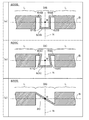
<<< §1. 先願力覚センサの基本構造部の特徴 >>>
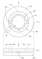
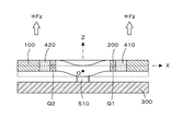
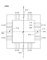
図1は、先願力覚センサの基本構造部の上面図(上段の図)および側面図(下段の図)である。上面図では、図の右方向にX軸、図の上方向にY軸が配置されており、紙面に垂直な手前方向がZ軸方向になる。一方、側面図では、図の右方向にX軸、図の上方向にZ軸が配置されており、紙面に垂直な奥行き方向がY軸方向になる。図示のとおり、この基本構造部は、受力体100、検出リング200、支持基板300、接続部材410,420、固定部材510,520によって構成されている。
<<< §1. Features of the basic structure of the first-application force sensor >>>
FIG. 1 is a top view (upper view) and a side view (lower view) of the basic structure of the prior application force sensor. In the top view, the X axis is arranged in the right direction of the drawing, and the Y axis is arranged in the upward direction of the drawing, and the front direction perpendicular to the paper surface is the Z axis direction. On the other hand, in the side view, the X axis is arranged in the right direction of the drawing, the Z axis is arranged in the upward direction of the drawing, and the depth direction perpendicular to the paper surface is the Y axis direction. As shown in the figure, this basic structure portion is constituted by a
受力体100は、Z軸が中心軸となるようにXY平面上に配置された円形平板状(ワッシャ状)のリングであり、外周面も内周面も円柱面を構成する。受力体100の役割は、検出対象となる力もしくはモーメントの作用を受け、これを検出リング200に伝達することにある。
The
一方、検出リング200は、受力体100と同様に、Z軸が中心軸となるようにXY平面上に配置された円形平板状(ワッシャ状)のリングであり、外周面も内周面も円柱面を構成する。ここに示す例の場合、検出リング200は、受力体100の内側に配置されている。すなわち、受力体100はXY平面上に配置された外側リング、検出リング200はXY平面上に配置された内側リングということになる。ここで、検出リング200の特徴は、検出対象となる力もしくはモーメントの作用により弾性変形を生じる点である。
On the other hand, the
接続部材410,420は、受力体100と検出リング200とを接続するための部材である。図示の例の場合、接続部材410は、X軸正領域に沿った位置において、受力体100の内周面と検出リング200の外周面とを接続し、接続部材420は、X軸負領域に沿った位置において、受力体100の内周面と検出リング200の外周面とを接続している。したがって、受力体100と検出リング200との間には、図示のとおり空隙部H1が確保されており、検出リング200の内側には、図示のとおり空隙部H2が確保されている。
The
図1の下段に示す側面図を見れば明らかなように、この例の場合、受力体100と検出リング200の厚み(Z軸方向の寸法)は同じであり、側面図では、検出リング200は受力体100の内側に完全に隠れた状態になっている。両リングの厚みは、必ずしも同じにする必要はないが、薄型センサ(Z軸方向の寸法ができるだけ小さいセンサ)を実現する上では、両リングを同じ厚みにするのが好ましい。
As apparent from the side view shown in the lower part of FIG. 1, in this example, the thickness (dimension in the Z-axis direction) of the
支持基板300は、径が受力体100の外径と等しい円盤状の基板であり、XY平面に平行な上面をもち、受力体100および検出リング200の下方に所定間隔をおいて配置される。固定部材510,520は、検出リング200を支持基板300に固定するための部材である。側面図では、固定部材510は固定部材520の奥に隠れて現れていないが、固定部材510,520は、検出リング200の下面と支持基板300の上面とを接続する役割を果たす。上面図に破線で示されているとおり、固定部材510,520は、Y軸に沿った位置に配置されている。
The
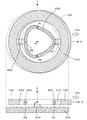
図2は、図1に示す基本構造部をXY平面で切断した横断面図(上段の図)およびXZ平面で切断した縦断面図(下段の図)である。XY平面で切断した横断面図の中心には、XYZ三次元直交座標系の原点Oが示されている。この図2では、検出リング200が、左右2カ所において、X軸に沿って配置された接続部材410,420を介して受力体100に接続されている状態が明瞭に示されている。
FIG. 2 is a cross-sectional view (upper drawing) of the basic structure shown in FIG. 1 cut along the XY plane and a vertical cross-sectional view (lower view) cut along the XZ plane. The origin O of the XYZ three-dimensional orthogonal coordinate system is shown at the center of the cross-sectional view cut along the XY plane. FIG. 2 clearly shows a state in which the
図3は、図1に示す基本構造部の支持基板300および固定部材510,520の上面図(上段の図)、ならびに、この基本構造部をYZ平面で切断した縦断面図(下段の図)である。図3の上面図は、図1の上面図を反時計まわりに90°回転させた状態に相当し、Y軸が左方向にとられている。また、図3の上面図では、検出リング200の位置が破線で示されている。一方、図3の縦断面図には、固定部材510,520によって、支持基板300の上方に検出リング200が固定されている状態が明瞭に示されている。
3 is a top view (upper view) of the
後述するように、支持基板300を固定した状態において、受力体100に様々な方向の力が作用すると、検出リング200が、作用した力に応じた態様で変形を生じることになる。先願力覚センサは、この変形態様を電気的に検出することにより、作用した力の検出を行う。したがって、検出リング200の弾性変形のしやすさは、センサの検出感度を左右するパラメータになる。弾性変形しやすい検出リング200を用いれば、微小な力が作用した場合でも検出可能な感度の高いセンサを実現することができるが、検出可能な力の最大値は抑制されることになる。逆に、弾性変形しにくい検出リング200を用いれば、検出可能な力の最大値を大きくとることができるが、感度は低下するため、微小な力の検出はできなくなる。
As will be described later, when forces in various directions are applied to the
検出リング200の弾性変形のしやすさは、Z軸方向の厚みおよび径方向の厚み(いずれも薄くするほど弾性変形しやすい)に依存して決まり、更に、その材質にも依存して決まる。したがって、実用上は、力覚センサの用途に応じて、検出リング200の各部の寸法や材質を選択する必要がある。後述するように、本発明で用いる検出リングでは、この点における改善がなされており、産業上の要望に応じて、設計の自由度をより向上させることができる。
The ease of elastic deformation of the
一方、受力体100および支持基板300は、力を検出する原理上、弾性変形を生じる部材である必要はない。むしろ、作用した力が検出リング200の変形に100%寄与するようにするためには、受力体100および支持基板300は、完全な剛体である方が好ましい。図示の例において、受力体100として、中心に空隙部H1を有するリング状構造体を用いた理由は、弾性変形しやすくするためではなく、内部に検出リング200を収容するためである。図示の例のように、検出リング200の外側にリング状の受力体100を配置する構成を採れば、基本構造部の厚みを小さくすることができ、より薄型の力覚センサが実現できる。
On the other hand, the
実用上、受力体100、検出リング200、支持基板300の材料としては、絶縁材料を利用するのであれば、プラスチックなどの合成樹脂を用いれば十分であり、導電材料を利用するのであれば、ステンレス、アルミニウムなどの金属を用いれば十分である。もちろん、絶縁材料と導電材料とを組み合わせて利用してもかまわない。
Practically, as the material of the
続いて、支持基板300を固定した状態において、受力体100に対して各座標軸方向の力および各座標軸まわりのモーメントが作用した場合に、この基本構造部にどのような現象が生じるかを考えてみる。
Subsequently, in the state where the
上述したとおり、受力体100および支持基板300は、作用した力が検出リング200の変形に100%寄与するようにするため、本来は、完全な剛体である方が好ましい。しかしながら、実際には、基本構造部を樹脂や金属で構成した場合、受力体100や支持基板300は完全な剛体にはならず、受力体100に力やモーメントが加わると、厳密に言えば、受力体100や支持基板300にも若干の弾性変形が生じることになる。ただ、受力体100や支持基板300に生じる弾性変形が、検出リング200に生じる弾性変形に比べてわずかな弾性変形であれば無視することができ、実質的に剛体と考えて支障はない。そこで、本願では、受力体100および支持基板300が剛体であり、力やモーメントによる弾性変形は、専ら検出リング200においてのみ生じるものとして説明を行うことにする。
As described above, the
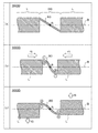
まず、支持基板300を固定した状態において、受力体100に対して、X軸方向の力が作用したときに、この基本構造部にどのような変化が生じるかを考えてみる。図4は、図1に示す基本構造部の受力体100にX軸正方向の力+Fxが作用したときの変形状態を示すXY平面における横断面図(上段の図)およびXZ平面における縦断面図(下段の図)である。支持基板300は固定されているため不動であるが、受力体100は、X軸正方向の力+Fxにより図の右方向へと移動する。その結果、検出リング200は図示のとおり変形する。なお、図に示す破線は、移動もしくは変形前の各リングの位置を示している。
First, let us consider what kind of change occurs in the basic structure when a force in the X-axis direction is applied to the
ここでは、この変形態様を説明する便宜上、2つの固定点P1,P2(黒丸で示す)と、2つの作用点Q1,Q2(白丸で示す)を考える。固定点P1,P2は、Y軸上に定義された点であり、図1に示す固定部材510,520の位置に対応するものである。すなわち、検出リング200は、この固定点P1,P2の位置において、固定部材510,520によって支持基板300に固定されている。一方、作用点Q1,Q2は、X軸上に定義される点であり、検出リング200は、この作用点Q1,Q2の位置において、接続部材410,420によって受力体100に接続されている。
Here, for the sake of convenience of explaining this deformation mode, two fixed points P1, P2 (indicated by black circles) and two action points Q1, Q2 (indicated by white circles) are considered. The fixed points P1 and P2 are points defined on the Y axis, and correspond to the positions of the fixing
このように、先願力覚センサにおいて、作用点は接続部材が接続される位置であり、固定点は固定部材が接続される位置である。そして、重要な点は、作用点と固定点とが異なる位置に配置される点である。図4に示す例の場合、固定点P1,P2と作用点Q1,Q2とはXY平面上の異なる位置に配置されている。これは、作用点と固定点とが同一位置を占めると、検出リング200に弾性変形が生じなくなるためである。
Thus, in the prior application force sensor, the action point is a position where the connecting member is connected, and the fixed point is a position where the fixing member is connected. An important point is that the action point and the fixed point are arranged at different positions. In the example shown in FIG. 4, the fixed points P1, P2 and the action points Q1, Q2 are arranged at different positions on the XY plane. This is because elastic deformation does not occur in the
さて、受力体100に対してX軸正方向の力+Fxが作用すると、図4に示すように、検出リング200の作用点Q1,Q2(白丸)には、図の右方向への力が加わることになる。ところが、検出リング200の固定点P1,P2(黒丸)の位置は固定されているため、可撓性をもった検出リング200は、基準の円形状態から、図示のような歪んだ状態へと変形することになる(なお、本願における変形状態を示す図は、変形状態を強調して示すため多少デフォルメされた図になっており、必ずしも正確な変形態様を示す図ではない)。具体的には、図示のとおり、点P1−Q1間および点P2−Q1間では、検出リング200の四分円弧の両端に引っ張り力が作用して四分円弧は内側に縮み、点P1−Q2間および点P2−Q2間では、検出リング200の四分円弧の両端に押圧力が作用して四分円弧は外側に膨らんでいる。
Now, when a force + Fx in the positive direction of the X-axis acts on the
受力体100に対してX軸負方向の力−Fxが作用した場合は、図4とは左右逆の現象が起きる。また、受力体100に対してY軸正方向の力+FyおよびY軸負方向の力−Fyが作用した場合は、図4上段における変形状態を90°回転させた現象が起きる。
When a force -Fx in the negative direction of the X-axis acts on the
次に、支持基板300を固定した状態において、受力体100に対して、Z軸方向の力が作用したときに、この基本構造部にどのような変化が生じるかを考えてみる。図5は、図1に示す基本構造部の受力体100にZ軸正方向の力+Fzが作用したときの変形状態を示すXZ平面における縦断面図である。支持基板300は固定されているため不動であるが、受力体100は、Z軸正方向の力+Fzにより図の上方向へと移動する。その結果、検出リング200は図示のとおり変形する。なお、図に示す破線は、移動もしくは変形前の各リングの位置を示している。
Next, let us consider what changes occur in the basic structure when a force in the Z-axis direction is applied to the
ここでも、変形態様の基本は、2つの固定点P1,P2の位置(固定部材510,520で固定された位置)は不動であり、2つの作用点Q1,Q2の位置が上方へ移動する、という点である。検出リング200は、固定点P1,P2の位置から作用点Q1,Q2の位置へ向けて緩やかに変形することになる。また、受力体100に対してZ軸負方向の力−Fzが作用した場合は、受力体100は、図の下方向へと移動する。その結果、検出リング200の変形態様は、図5とは上下逆になる。
Here, the basis of the deformation mode is that the positions of the two fixed points P1 and P2 (the positions fixed by the fixing
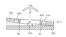
続いて、支持基板300を固定した状態において、受力体100に対して、Y軸まわりのモーメントが作用したときに、この基本構造部にどのような変化が生じるかを考えてみる。図6は、図1に示す基本構造部の受力体100にY軸正まわりのモーメント+Myが作用したときの変形状態を示すXZ平面における縦断面図である。なお、本願では、所定の座標軸まわりに作用するモーメントの符号を、当該座標軸の正方向に右ネジを進めるための当該右ネジの回転方向を正にとることにする。たとえば、図6に示すモーメント+Myの回転方向は、右ネジをY軸正方向に進めるための回転方向になる。
Next, let us consider what kind of change occurs in the basic structure when a moment about the Y-axis acts on the
この場合も、支持基板300は固定されているため不動であるが、受力体100は、Y軸正まわりのモーメント+Myを受けて、図の原点Oを中心として時計まわりに回転する。その結果、作用点Q1は下方に移動し、作用点Q2は上方に移動する。検出リング200は、固定点P1,P2の位置(固定部材510,520で固定された位置)から作用点Q1,Q2の位置へ向けて緩やかに変形することになる。受力体100に対してY軸負まわりのモーメント−Myが作用した場合は、図6とは左右逆の現象が起きる。また、受力体100に対してX軸正まわりのモーメント+MxおよびX軸負まわりのモーメント−Mxが作用した場合は、上面図において変形状態を90°回転させた現象が起きる。
In this case as well, the
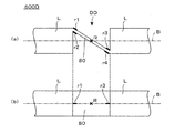
最後に、支持基板300を固定した状態において、受力体100に対して、Z軸まわりのモーメントが作用したときに、この基本構造部にどのような変化が生じるかを考えてみる。図7は、図1に示す基本構造部の受力体100にZ軸正まわりのモーメント+Mzが作用したときの変形状態を示すXY平面における横断面図である。この場合も、支持基板300は固定されているため不動であるが、受力体100は、Z軸正まわりのモーメント+Mzを受けて、図の原点Oを中心として反時計まわりに回転する。
Finally, let us consider what kind of change occurs in this basic structure when a moment around the Z-axis acts on the
その結果、検出リング200の作用点Q1,Q2には、図において反時計回りの力が加わることになる。ところが、検出リング200の固定点P1,P2の位置は固定されているため、可撓性をもった検出リング200は、基準の円形状態から、図示のような歪んだ状態へと変形することになる。具体的には、図示のとおり、点P2−Q1間および点P1−Q2間では、検出リング200の四分円弧の両端に引っ張り力が作用して四分円弧は内側に縮み、点P1−Q1間および点P2−Q2間では、検出リング200の四分円弧の両端に押圧力が作用して四分円弧は外側に膨らんでおり、全体的に楕円状に変形している。一方、受力体100に対してZ軸負まわりのモーメント−Mzが作用した場合は、受力体100は、図の原点Oを中心として時計まわりに回転するため、図7を裏返しにした変形状態が起きる。
As a result, a counterclockwise force is applied to the action points Q1 and Q2 of the
以上、図1に示す基本構造部の支持基板300を固定した状態において、受力体100に対して各座標軸方向の力および各座標軸まわりのモーメントが作用した場合に、検出リング200に生じる変形態様を説明したが、これらの変形態様は互いに異なり、また、作用した力やモーメントの大きさにより変形量も異なる。そこで、検出リング200の弾性変形を検出し、その態様や大きさに関する情報を収集すれば、各座標軸方向の力および各座標軸まわりのモーメントをそれぞれ別個独立して検出することができる。これが、先願力覚センサにおける検出動作の基本原理である。先願力覚センサでは、このような原理に基づく検出を行うために、これまで述べてきた基本構造部に、更に、容量素子と検出回路とを付加することになる。
As described above, in the state where the
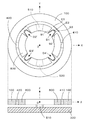
<<< §2. 先願力覚センサの検出原理 >>>
先願力覚センサでは、図1に示す基本構造部の特定箇所の変位を測定することにより、作用した力およびモーメントの向きと大きさを検出することになる。この変位検出のために、固定補助体350が付加される。
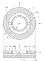
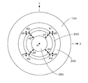
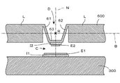
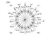
<<< §2. Detection principle of first-application force sensor >>>
In the first application force sensor, the direction and magnitude of the applied force and moment are detected by measuring the displacement of a specific portion of the basic structure shown in FIG. For this displacement detection, a fixing
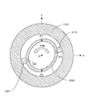
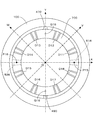
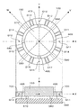
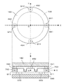
図8は、図1に示す基本構造部に、変位検出用の固定補助体350を付加した例を示す上面図(上段の図)および側面図(下段の図)である。図示のとおり、この基本構造部では、受力体100の内側に検出リング200が配置されており、更にその内側に固定補助体350が配置されている。この固定補助体350は、Z軸を中心軸とする円柱状の物体であり、下面が支持基板300の上面に固定されている。固定補助体350の外周面は、空隙部H2を挟んで、検出リング200の内周面に対向している。
FIG. 8 is a top view (upper view) and a side view (lower view) showing an example in which a displacement assisting fixing
図9は、図8に示す基本構造部をXY平面で切断した横断面図(上段の図)およびVZ平面で切断した縦断面図(下段の図)である。ここで、V軸は、XYZ三次元直交座標系における原点Oを通り、正の領域がXY平面の第1象限、負の領域がXY平面の第3象限に位置し、X軸に対して45°をなす軸である。また、W軸は、XYZ三次元直交座標系における原点Oを通り、正の領域がXY平面の第2象限、負の領域がXY平面の第4象限に位置し、V軸に対して直交する軸である。図9の上段に示す横断面図は、V軸正方向を右方向、W軸正方向を上方向にとった図であり、図2の上段に示す基本構造部に固定補助体350を付加し、これを時計まわりに45°回転させた図に対応する。また、図9の下段の縦断面図は、VZ平面で切断した縦断面図であるため、右方向はV軸正方向になっている。
FIG. 9 is a cross-sectional view (upper drawing) of the basic structure shown in FIG. 8 cut along the XY plane and a vertical cross-sectional view (lower view) cut along the VZ plane. Here, the V axis passes through the origin O in the XYZ three-dimensional orthogonal coordinate system, the positive region is located in the first quadrant of the XY plane, the negative region is located in the third quadrant of the XY plane, and is 45 with respect to the X axis. It is the axis that makes the °. The W axis passes through the origin O in the XYZ three-dimensional orthogonal coordinate system, the positive region is located in the second quadrant of the XY plane, the negative region is located in the fourth quadrant of the XY plane, and is orthogonal to the V axis. Is the axis. 9 is a diagram in which the V-axis positive direction is the right direction and the W-axis positive direction is the upward direction, and a fixing
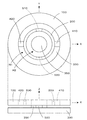
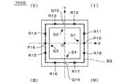
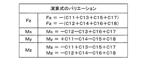
§1で述べたとおり、検出リング200上には、Y軸上に2つの固定点P1,P2が配置され、X軸上に2つの作用点Q1,Q2が配置されている。ここでは、更に、4つの測定点R1〜R4(×印で示す)を定義する。図示のとおり、第1の測定点R1はV軸正領域に、第2の測定点R2はW軸正領域に、第3の測定点R3はV軸負領域に、第4の測定点R4はW軸負領域に、それぞれ配置されている。結局、図9の上段の横断面図において、検出リング200の外周輪郭円と内周輪郭円との中間に位置する円として基本環状路B(図には、太い一点鎖線で示す)を定義した場合、各点Q1,R1,P1,R2,Q2,R3,P2,R4は、この順番どおりに、円形の基本環状路B上に等間隔に配置されていることになる。4つの測定点R1〜R4をこのような位置に定義するのは、検出リング200の弾性変形に起因して生じる変位が最も顕著になるためである。
As described in §1, on the
この4つの測定点R1〜R4の半径方向の変位を検出するには、図9の上段の横断面図に矢印で示す距離d1,d2,d3,d4を測定すればよい。これらの距離d1,d2,d3,d4は、検出リング200の内周面の、各測定点R1,R2,R3,R4近傍に位置する測定対象面と、固定補助体350の外周に位置し、測定対象面に対向する対向基準面との距離であり、当該距離が大きくなれば、測定点近傍部分が半径方向に膨らんでいることを示し、当該距離が小さくなれば、測定点近傍部分が半径方向に縮んでいることを示すことになる。したがって、これらの距離を電気的に検出する容量素子を用意しておけば、各測定点近傍部分の半径方向に関する変形量を測定することができる。
In order to detect the displacement in the radial direction of these four measurement points R1 to R4, distances d1, d2, d3, and d4 indicated by arrows in the upper cross section of FIG. 9 may be measured. These distances d1, d2, d3, and d4 are located on the measurement target surface of the inner peripheral surface of the
一方、4つの測定点R1〜R4の上下方向(Z軸方向)の変位を検出するには、図9の下段の縦断面図に矢印で示す距離d5,d7および図示されていない距離d6,d8(距離d6は、固定補助体350の奥に位置する測定点R2の直下の距離、距離d8は、固定補助体350の手前に位置する測定点R4の直下の距離)を測定すればよい。これらの距離d5,d6,d7,d8は、検出リング200の下面の、各測定点R1,R2,R3,R4近傍に位置する測定対象面と、支持基板300の上面に位置し、測定対象面に対向する対向基準面との距離であり、当該距離が大きくなれば、測定点近傍部分が上方向に変位していることを示し、当該距離が小さくなれば、測定点近傍部分が下方向に変位していることを示すことになる。したがって、これらの距離を電気的に検出する検出素子を用意しておけば、各測定点近傍部分の上下方向に関する変形量を測定することができる。
On the other hand, in order to detect the displacement in the vertical direction (Z-axis direction) of the four measurement points R1 to R4, distances d5 and d7 indicated by arrows in the lower longitudinal sectional view of FIG. 9 and distances d6 and d8 (not shown). (Distance d6 may be a distance immediately below measurement point R2 located in the back of fixed
このように、4つの測定点R1〜R4の半径方向の変位と上下方向の変位とを測定することができれば、検出リング200の全体的な変形態様および変形量を把握することができ、XYZ三次元直交座標系における各座標軸方向の力および各座標軸まわりのモーメントの6軸成分を検出することが可能になる。図10は、この6軸成分を検出するために必要な距離測定箇所を示す上面図である。すなわち、この例では、前述したとおり、第1の測定点R1について、距離d1(半径方向の変位)と距離d5(上下方向の変位)とが測定され、第2の測定点R2について、距離d2(半径方向の変位)と距離d6(上下方向の変位)とが測定され、第3の測定点R3について、距離d3(半径方向の変位)と距離d7(上下方向の変位)とが測定され、第4の測定点R4について、距離d4(半径方向の変位)と距離d8(上下方向の変位)とが測定されることになる。
Thus, if the radial displacement and the vertical displacement of the four measurement points R1 to R4 can be measured, the overall deformation mode and deformation amount of the
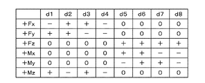
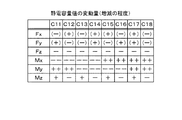
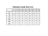
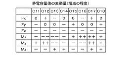
図11は、図10に示す基本構造部において、支持基板300を固定した状態で受力体100に対して各座標軸方向の力および各座標軸まわりのモーメントが作用したときの距離d1〜d8の変化を示すテーブルである。このテーブルで「+」は距離が大きくなることを示し、「−」は距離が小さくなることを示し、「0」は距離が変動しないことを示している。このような結果が得られることは、§1で説明した検出リング200の具体的な変形態様を考えれば、容易に理解できよう。
FIG. 11 shows changes in the distances d1 to d8 when a force in the direction of each coordinate axis and a moment around each coordinate axis act on the
たとえば、受力体100に対してX軸正方向の力+Fxが作用すると、検出リング200は、図4に示すように、点P1−Q1間および点P2−Q1間の四分円弧は内側に縮み、点P1−Q2間および点P2−Q2間の四分円弧は外側に膨らむように変形する。したがって、距離d1,d4は小さくなり、距離d2,d3は大きくなる。このとき、検出リング200に上下方向の変形は生じないので、距離d5〜d8は変動しない。図11のテーブルの+Fxの行は、このような結果を示している。同様の理由により、Y軸正方向の力+Fyが作用した場合は、図11のテーブルの+Fyの行に示す結果が得られる。
For example, when a force + Fx in the positive direction of the X-axis acts on the
また、受力体100に対してZ軸正方向の力+Fzが作用すると、検出リング200は、図5に示すように変形するので、距離d5〜d8は大きくなる。このとき、検出リング200に半径方向の変形は生じないので、距離d1〜d4は変動しない。図11のテーブルの+Fzの行は、このような結果を示している。
Further, when a force + Fz in the positive direction of the Z-axis acts on the
そして、受力体100に対してY軸正まわりのモーメント+Myが作用すると、検出リング200は、図6に示すように変形し、図の右半分は下方へ変位し、図の左半分は上方へ変位するので、距離d5,d8は小さくなり、距離d6,d7は大きくなる。このとき、検出リング200に半径方向の変形は生じないので、距離d1〜d4は変動しない。図11のテーブルの+Myの行は、このような結果を示している。同様の理由により、X軸正まわりのモーメント+Mxが作用した場合は、図11のテーブルの+Mxの行に示す結果が得られる。
When a moment + My about the positive Y-axis acts on the
最後に、受力体100に対してZ軸正まわりのモーメント+Mzが作用した場合、検出リング200は、図7に示すように変形し、点P1−Q1間および点P2−Q2間の四分円弧は外側に膨らみ、点P1−Q2間および点P2−Q1間の四分円弧は内側に縮むように変形する。したがって、距離d1,d3は大きくなり、距離d2,d4は小さくなる。このとき、検出リング200に上下方向の変形は生じないので、距離d5〜d8は変動しない。図11のテーブルの+Mzの行は、このような結果を示している。
Finally, when a moment + Mz about the positive Z-axis acts on the
なお、図11のテーブルは、正方向の力および正まわりのモーメントが作用した場合の結果を示しているが、負方向の力および負まわりのモーメントが作用した場合は、「+」と「−」が逆転した結果が得られることになる。結局、距離d1〜d8の変化パターンは、6軸成分が作用した個々の場合のそれぞれで異なり、しかも作用した力やモーメントが大きくなればなるほど、距離の変動量も大きくなる。そこで、検出回路により、これら距離d1〜d8の測定値に基づく所定の演算を施せば、6軸成分の検出値を独立して出力することが可能になる。 The table of FIG. 11 shows the result when a positive force and a positive moment are applied. However, when a negative force and a negative moment are applied, “+” and “−” "Will be reversed. After all, the change pattern of the distances d1 to d8 is different in each case where the six-axis component is applied, and the greater the force or moment that is applied, the greater the distance variation. Therefore, if the detection circuit performs a predetermined calculation based on the measurement values of the distances d1 to d8, it is possible to independently output the detection values of the six-axis components.
先願力覚センサは、図8に示す基本構造部に、更に、容量素子と検出回路を付加したものであり、各部に配置した容量素子の静電容量値の変化を電気的に検出することにより、特定箇所の変位を測定し、作用した力およびモーメントの向きと大きさを検出するものである。 The first-application force sensor is obtained by adding a capacitive element and a detection circuit to the basic structure shown in FIG. 8 and electrically detecting a change in the capacitance value of the capacitive element arranged in each part. Thus, the displacement at a specific location is measured, and the direction and magnitude of the applied force and moment are detected.
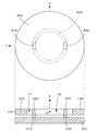
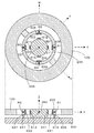
図12は、図9に示す基本構造部に容量素子を付加して構成される力覚センサを、XY平面で切断した横断面図(上段の図)およびVZ平面で切断した縦断面図(下段の図)である。図9に示す基本構造部と図12に示す力覚センサとを比較すると、後者では、16枚の電極E11〜E18,E21〜E28が付加されていることがわかる。これら16枚の電極により構成される8組の容量素子は、前述した8通りの距離d1〜d8を測定する検出素子として機能する。 FIG. 12 is a cross-sectional view (upper view) cut along the XY plane and a vertical cross-sectional view (lower step) cut along the VZ plane of the force sensor formed by adding a capacitive element to the basic structure shown in FIG. Figure) Comparing the basic structure shown in FIG. 9 and the force sensor shown in FIG. 12, it can be seen that 16 electrodes E11 to E18 and E21 to E28 are added in the latter. Eight sets of capacitive elements constituted by these 16 electrodes function as detection elements for measuring the eight distances d1 to d8 described above.
図12上段の横断面図に示されているとおり、検出リング200の内周面の、4つの測定点R1〜R4の近傍部分(測定対象面)には、それぞれ変位電極E21〜E24が設けられている。また、検出リング200の下面の、4つの測定点R1〜R4の近傍部分(測定対象面)には、それぞれ変位電極E25〜E28(図では、破線で示されている)が設けられている。これら8枚の変位電極E21〜E28は、文字通り、検出リング200の変形によって変位を生じる電極である。
As shown in the cross-sectional view in the upper part of FIG. 12, displacement electrodes E21 to E24 are provided in the vicinity of the four measurement points R1 to R4 (measurement target surface) on the inner peripheral surface of the
一方、これら8枚の変位電極E21〜E28に対向する位置(対向基準面)に、8枚の固定電極E11〜E18が設けられている。これら8枚の固定電極E11〜E18は、文字通り、支持基板300に直接もしくは間接的に固定された電極であり、検出リング200の変形にかかわらず、常に定位置を維持する。具体的には、円柱状の固定補助体350の外周面には、変位電極E21〜E24に対向する位置に固定電極E11〜E14が設けられており、これらの電極は固定補助体350を介して支持基板300上に間接的に固定されている。また、支持基板300の上面には、変位電極E25〜E28に対向する位置に固定電極E15〜E18が直接固定されている(図12下段の縦断面図には、変位電極E15,E17のみが現れているが、変位電極E16は、固定補助体350の奥に位置し、変位電極E18は、固定補助体350の手前に位置する)。
On the other hand, eight fixed electrodes E11 to E18 are provided at positions (opposing reference planes) facing these eight displacement electrodes E21 to E28. These eight fixed electrodes E11 to E18 are literally fixed directly or indirectly to the
なお、本願図面では、図示の便宜上、各変位電極および各固定電極の厚みの実寸を無視して描いてある。たとえば、各電極を蒸着層やメッキ層によって構成した場合、その厚みは数μm程度であり、図12に示された各電極E11〜E28の図面上の厚みは、実寸比上は、正しい厚みにはなっていない。 In the drawings of the present application, for convenience of illustration, the actual thicknesses of the displacement electrodes and the fixed electrodes are ignored. For example, when each electrode is constituted by a vapor deposition layer or a plating layer, the thickness is about several μm, and the thickness on the drawing of each of the electrodes E11 to E28 shown in FIG. It is not.
結局、図12に示す例の場合、検出リング200の内周面および下面の、各測定点R1〜R4近傍に位置する測定対象面に設けられた8組の変位電極E21〜E28と、固定補助体350の外周面および支持基板300の上面の、各測定対象面に対向する位置に定義された対向基準面に設けられた8組の固定電極E11〜E18と、によって、8組の容量素子が構成されることになる。そして、先願力覚センサは、これら8組の容量素子の静電容量値を電気的に検出することにより、各測定点R1〜R4の変位を測定し、図11に示すテーブルに基づいて、受力体100に作用した力およびモーメントの向きと大きさを検出することになる。
After all, in the case of the example shown in FIG. 12, eight sets of displacement electrodes E21 to E28 provided on the measurement target surfaces located in the vicinity of the measurement points R1 to R4 on the inner peripheral surface and the lower surface of the
このように、先願力覚センサは、図12に示すような単純な基本構造部を利用して構成することができるが、様々な箇所に容量素子を配置する必要があるため、容量素子を構成する電極の構成が複雑にならざるを得ない。具体的には、基本構造部に容量素子を付加するためには、固定電極E15〜E18や変位電極E25〜E28のように、基板面(XY平面)に対して平行な電極層を形成する工程と、固定電極E11〜E14や変位電極E21〜E24のように、基板面(XY平面)に対して垂直な電極層を形成する工程と、を行う必要がある。一般に、前者の工程は、半導体製造プロセスなどで広く利用されている方法を利用することができるため比較的容易であるが、後者の工程は、複雑な手法を取り入れる必要があり、量産化を行う上で問題が生じやすい。 As described above, the prior-application force sensor can be configured by using a simple basic structure as shown in FIG. 12, but it is necessary to arrange capacitive elements at various locations. The configuration of the electrodes to be configured must be complicated. Specifically, in order to add a capacitive element to the basic structure, a step of forming an electrode layer parallel to the substrate surface (XY plane) like the fixed electrodes E15 to E18 and the displacement electrodes E25 to E28. And a step of forming an electrode layer perpendicular to the substrate surface (XY plane) like the fixed electrodes E11 to E14 and the displacement electrodes E21 to E24. In general, the former process is relatively easy because a method widely used in a semiconductor manufacturing process or the like can be used. However, the latter process needs to adopt a complicated method and is mass-produced. Problems are likely to occur above.
しかも、個々の容量素子を構成する一対の電極の相対位置は、検出精度に影響を与える重大な要因になる。特に、図12に示す例のように、複数の容量素子を対称性をもたせて配置し、これらを用いて差分検出を行う場合、個々の容量素子ごとに対向電極が平行になるようにするとともに、複数の容量素子についての電極間隔が互いに等しくなるような調整が必要になる。このため、先願力覚センサには、商業的に利用する場合に、生産効率が低下し、コストが高騰するという問題がある。 In addition, the relative position of the pair of electrodes constituting each capacitive element becomes a significant factor affecting the detection accuracy. In particular, as in the example shown in FIG. 12, when a plurality of capacitive elements are arranged with symmetry and difference detection is performed using them, the counter electrode is made parallel to each capacitive element. It is necessary to make adjustments so that the electrode intervals of the plurality of capacitive elements are equal to each other. For this reason, the prior application force sensor has a problem that when it is used commercially, the production efficiency is lowered and the cost is increased.
本発明は、先願力覚センサにおけるこのような問題を解決するため、検出リングの特定箇所に弾性変形を生じる検出部を設ける構造を採用することにより、設計の自由度を向上させ、生産効率を高めることができる新たな工夫を提案するものである。以下、本発明を具体的な実施形態に基づいて詳述する。 In order to solve such a problem in the prior-application force sensor, the present invention adopts a structure in which a detection unit that generates elastic deformation at a specific portion of the detection ring is employed, thereby improving the degree of freedom in design and improving the production efficiency. It proposes a new device that can improve Hereinafter, the present invention will be described in detail based on specific embodiments.
<<< §3. 本発明の基本的実施形態 >>>
<3−1.検出リングの構造>
図13は、本発明の基本的実施形態(第1の実施形態)に係る力覚センサに用いる検出リング600の斜視図(図(a) )、側面図(図(b) )、下面図(図(c) )である。図1に示す先願力覚センサに用いられていた検出リング200が、単純な円環状の構造体であるのに対して、図13に示す本願力覚センサに用いる検出リング600は、この単純な円環状の構造体の4箇所に、弾性変形する板状片を組み合わせて構成された検出部D1〜D4が設けられている。
<<< §3. Basic embodiment of the present invention >>
<3-1. Structure of detection ring>
FIG. 13 is a perspective view (FIG. (A)), a side view (FIG. (B)), a bottom view (bottom view) of the
別言すれば、図13に示す検出リング600は、図1に示す検出リング200に対して、部分的な材料除去加工を施すことにより得られた部材であり、この材料除去加工を施した部分によって、図示のような検出部D1〜D4が形成される。図1に示す検出リング200は、Z軸を中心軸として配置された板状部材の中央部に、貫通開口部を形成することにより得られる。図13に示す検出リング600は、こうして得られた検出リング200に対して、更に、部分的な材料除去加工を施すことにより得られる。4組の検出部D1〜D4は、このような材料除去加工によって得られた部分ということになる。もっとも、実際に検出リング600を量産する場合は、必ずしも材料除去加工を行う必要はなく、たとえば、鋳型を用いた鋳造、樹脂の成形、プレス加工等によって製造してもかまわない。
In other words, the
ここでは、説明の便宜上、図示のようにXYZ三次元座標系を定義し、検出リング600をZ軸を中心軸としてXY平面に配置した状態を示す。図13(a) は、この検出リング600を斜め下方から見た斜視図である。図示のとおり、この検出リング600は、4組の検出部D1〜D4と、これら検出部D1〜D4を相互に連結する4組の連結部L1〜L4と、を有している。すなわち、検出リング600は、各検出部D1〜D4の間にそれぞれ各連結部L1〜L4を介挿した構造を有している。
Here, for convenience of explanation, an XYZ three-dimensional coordinate system is defined as shown, and the
図13(b) の側面図(図が繁雑になるのを避けるため、外周面の部分のみを示す)の検出部D4に示されているように、この実施形態における検出部Dは、第1の変形部61、第2の変形部62、変位部63という3枚の板状片(板バネ)によって構成されている。他の検出部D1〜D3も同様の構造を有する。このように、各検出部D1〜D4は、各連結部L1〜L4に比べて肉厚の薄い板状片によって構成されているため、各連結部L1〜L4に比べて弾性変形しやすいという性質を有している。したがって、後述するように、検出リング600に外力が作用した場合、当該外力に基づく検出リング600の弾性変形は、検出部D1〜D4に集中して生じ、連結部L1〜L4の弾性変形は、実用上、無視し得る程度である。
As shown in the detection unit D4 in the side view of FIG. 13 (b) (only the portion of the outer peripheral surface is shown in order to avoid the figure becoming complicated), the detection unit D in this embodiment is the first Are formed by three plate-like pieces (plate springs), namely, a deforming
このように、先願力覚センサに用いられていた検出リング200は、均一な円環状構造を有していたため、外力が作用するとリング全体にわたって弾性変形が生じるのに対して、本願力覚センサに用いる検出リング600では、弾性変形が生じやすい検出部D1〜D4に変形が集中することになる。このため、より効率的な変形を生じさせることが可能になり、より効率的な検出が可能になる。具体的には、検出感度を高めるだけでなく、検出部の形状や構造を工夫することにより、弾性変形の態様を自由に設定することができるようになる。なお、図示の検出部D1〜D4についての具体的な弾性変形の態様については後に詳述する。
As described above, the
図13(c) は、図13(a) に示す検出リング600を下方から見上げた下面図であり、X軸を右方向にとると、Y軸は下方向を向いた軸になる。図示のとおり、X軸上に配置されている連結部L1を始点として時計まわりに、連結部L1,検出部D1,連結部L2,検出部D2,連結部L3,検出部D3,連結部L4,検出部D4の順に配置されている。後述するように、Y軸上の固定点P1,P2(黒丸で示す)は支持基板に固定され、X軸上の作用点Q1,Q2(白丸で示す)には受力体から加えられた外力が作用する。その結果、各検出部D1〜D4には、当該外力に応じた弾性変形が生じる。
FIG. 13C is a bottom view of the
図14は、図13に示す検出リング600の領域分布を示す上面図である(網目状のハッチングは、検出部D1〜D4の領域を示すためのものであり、断面を示すものではない)。上面図であるため、図13(c) とは逆に、検出リング600上には反時計まわりに、L1,D1,L2,D2,L3,D3,L4,D4がこの順に配置されている。図示のとおり、XY平面上において、原点Oを中心としてX軸を反時計まわりに45°回転させた座標軸としてV軸が定義され、原点Oを中心としてY軸を反時計まわりに45°回転させた座標軸としてW軸が定義されている。図の<I>,<II>,<III>,<IV>は、XY二次元座標系における第1象限〜第4象限を示している。4組の検出部D1,D2,D3,D4は、それぞれ第1象限,第2象限,第3象限,第4象限に配置されている。
FIG. 14 is a top view showing a region distribution of the
図15は、図13に示す検出リング600について、XY平面上に定義された基本環状路Bおよびこの基本環状路B上に定義された各点を示す平面図である。図に太い一点鎖線で示す基本環状路Bは、XY平面上に配置された原点Oを中心とする円であり、検出リング600は、この基本環状路Bに沿って伸びる環状構造体になる。図には、検出リング600の内側輪郭線と外側輪郭線の位置が実線で示されている。図示の実施例の場合、基本環状路Bは、検出リング600の内側輪郭線と外側輪郭線との中間位置を通るXY平面上の円であり、検出リング600の環状肉厚部分(連結部L1〜L4)の中心線になる。
FIG. 15 is a plan view showing the basic annular path B defined on the XY plane and each point defined on the basic annular path B for the
4組の検出点R1〜R4は、この基本環状路B上の点として定義される。具体的には、第1の検出点R1は、正のV軸と基本環状路Bとの交点位置に定義され、第2の検出点R2は、正のW軸と基本環状路Bとの交点位置に定義され、第3の検出点R3は、負のV軸と基本環状路Bとの交点位置に定義され、第4の検出点R4は、負のW軸と基本環状路Bとの交点位置に定義されている。これら検出点R1〜R4は、それぞれ検出部D1〜D4の配置を示すものである。すなわち、図14に網目状のハッチング領域として示すように、第1の検出部D1は第1の検出点R1の位置に配置され、第2の検出部D2は第2の検出点R2の位置に配置され、第3の検出部D3は第3の検出点R3の位置に配置され、第4の検出部D4は第4の検出点R4の位置に配置されている。 Four sets of detection points R1 to R4 are defined as points on the basic circular path B. Specifically, the first detection point R1 is defined at the intersection point between the positive V-axis and the basic annular path B, and the second detection point R2 is the intersection point between the positive W-axis and the basic annular path B. The third detection point R3 is defined as the intersection position between the negative V-axis and the basic annular path B, and the fourth detection point R4 is the intersection between the negative W-axis and the basic annular path B. Defined in position. These detection points R1 to R4 indicate the arrangement of the detection units D1 to D4, respectively. That is, as shown in FIG. 14 as a mesh-shaped hatching region, the first detection unit D1 is arranged at the position of the first detection point R1, and the second detection unit D2 is at the position of the second detection point R2. The third detection unit D3 is arranged at the position of the third detection point R3, and the fourth detection unit D4 is arranged at the position of the fourth detection point R4.
一方、図15に黒丸で示されている点P1,P2は固定点、白丸で示されている点Q1,Q2は作用点である。後述するように、固定点P1,P2は支持基板300に対して固定される点になり、作用点Q1,Q2は受力体100からの力が作用する点になる。図示の例の場合、固定点P1,P2は、Y軸と基本環状路Bとの交点位置に定義され、作用点Q1,Q2は、X軸と基本環状路Bとの交点位置に定義されている。したがって、この検出リング600を用いた力覚センサでは、Y軸上の2点P1,P2を固定した状態において、X軸上の2点Q1,Q2に作用した力もしくはモーメントを、V軸およびW軸上の検出点R1〜R4に配置された4組の検出部D1〜D4の弾性変形に基づいて検出することになる。
On the other hand, points P1 and P2 indicated by black circles in FIG. 15 are fixed points, and points Q1 and Q2 indicated by white circles are action points. As will be described later, the fixed points P1 and P2 are points fixed to the
図15に示すとおり、固定点P1,P2と作用点Q1,Q2とは、基本環状路Bに沿って交互に配置されている。このような交互配置は、後述するように、検出対象となる外力が作用したときに、検出リング600に効果的な変形を生じさせる上で重要である。また、4組の検出点R1〜R4は、隣接する固定点と作用点との間に配置されている。このような配置も、検出対象となる外力が作用したときに、各検出部D1〜D4に効果的な変位を生じさせる上で重要である。
As shown in FIG. 15, the fixed points P <b> 1 and P <b> 2 and the action points Q <b> 1 and Q <b> 2 are alternately arranged along the basic annular path B. Such alternate arrangement is important in causing effective deformation of the
<3−2.基本的実施形態の構造>
続いて、本発明の基本的実施形態(第1の実施形態)に係る力覚センサの構造を説明する。図16は、当該実施形態に係る力覚センサの基本構造部の上面図(上段の図)およびこれをXZ平面で切断した側断面図(下段の図)である。図示のとおり、この基本構造部は、受力体100と、検出リング600と、支持基板300とを備えている。
<3-2. Structure of basic embodiment>
Next, the structure of the force sensor according to the basic embodiment (first embodiment) of the present invention will be described. FIG. 16 is a top view (upper view) of the basic structure portion of the force sensor according to the embodiment and a side cross-sectional view (lower view) cut along the XZ plane. As illustrated, the basic structure includes a
検出リング600は、§3−1で詳述したとおり、図13に示す構造を有する円環状の部材であり、4組の検出部D1〜D4を有している。受力体100は、この検出リング600の外側を取り囲むように配置された円環状の部材である。一方、支持基板300は、下段の側断面図に示されているとおり、検出リング600および受力体100の下方に配置された円盤状の部材である。受力体100の内周面と検出リング600の外周面との間は、X軸に沿った位置に配置された2本の接続部材410,420によって接続され、検出リング600の下面と支持基板300の上面との間は、Y軸に沿った位置に配置された固定部材510,520によって接続されている。
As described in detail in §3-1, the
図2に示す先願発明の基本構造部と図16に示す本発明の基本構造部とを比較すると、両者の本質的な相違点は、前者における検出リング200が、後者では検出リング600に置き換えられている点だけである。その他の各構成要素については、寸法や形状に若干の違いがあるが、本質的な機能に相違はないため、図16では、両者間で対応する構成要素について、検出リングを除いて同一符号を用いて示してある。図2に示す検出リング200が、単なるワッシャ状の円環状構造体であるのに対して、図16に示す検出リング600は、4箇所に検出部D1〜D4を有する円環状構造体である。このため、検出リング600に外力(力もしくはモーメント)が作用すると、前述したとおり、専ら、検出部D1〜D4に変形が集中することになる。
Comparing the basic structure of the invention of the prior application shown in FIG. 2 with the basic structure of the present invention shown in FIG. 16, the essential difference between the two is that the
そこで、以下、各検出部D1〜D4の構造とその変形態様についての説明を行う。図17は、図13に示す検出リング600の検出部D1〜D4の詳細構造を示す部分断面図である。4組の検出部D1〜D4は、いずれも同一の構造を有している。図17に示す検出部Dは、これら4組の検出部D1〜D4を代表するものであり、検出リング600を、基本環状路Bを含む円柱面で切断したときの断面部分を示している。図17(a) は、外力が作用していない状態、図17(b) は、外力の作用により検出部Dに圧縮力f1が作用した状態、図17(c) は、外力の作用により検出部Dに伸張力f2が作用した状態をそれぞれ示している。
Therefore, hereinafter, the structure of each of the detection units D1 to D4 and its modification will be described. FIG. 17 is a partial cross-sectional view showing a detailed structure of detection portions D1 to D4 of
図17(a) に示すとおり、検出部Dの左右両脇には、連結部Lが位置している。この連結部Lは、4組の連結部L1〜L4のいずれかに相当する。たとえば、図17(a) に示す検出部Dが、図13に示されている第4の検出部D4の場合、その右脇に配置されている連結部Lは、図13に示す連結部L1に相当し、その左脇に配置されている連結部Lは、図13に示す連結部L4に相当する。 As shown in FIG. 17 (a), the connecting portions L are located on the left and right sides of the detecting portion D. The connecting portion L corresponds to one of the four sets of connecting portions L1 to L4. For example, when the detection unit D shown in FIG. 17 (a) is the fourth detection unit D4 shown in FIG. 13, the connecting part L arranged on the right side thereof is the connecting part L1 shown in FIG. The connecting portion L disposed on the left side corresponds to the connecting portion L4 shown in FIG.
図示のとおり、検出部Dは、検出対象となる外力の作用により弾性変形を生じる第1の変形部61と、検出対象となる外力の作用により弾性変形を生じる第2の変形部62と、第1の変形部61および第2の変形部62の弾性変形により変位を生じる変位部63と、を有しており、左脇に配置された連結部Lの端部と右脇に配置された連結部Lの端部との間に配置されている。
As illustrated, the detection unit D includes a
ここに示す例の場合、第1の変形部61は、可撓性を有する第1の板状片によって構成され、第2の変形部62は、可撓性を有する第2の板状片によって構成され、変位部63は、第3の板状片によって構成されている。実際には、検出リング600は、金属(ステンレス、アルミニウムなど)や合成樹脂(プラスチックなど)といった同一材料からなる構造体によって構成される。第1の板状片61、第2の板状片62、変位部63は、連結部Lに比べて肉厚の薄い板状の部材であるため可撓性を有することになる。
In the case of the example shown here, the 1st deformation |
なお、ここに示す例の場合、変位部63も肉厚の薄い板状の部材であるため可撓性を有しているが、変位部63は必ずしも可撓性をもった部材である必要はない(もちろん、可撓性があってもよい)。変位部63の役割は、外力が作用したときに変位を生じることであり、そのような変位を生じさせるには、第1の変形部61および第2の変形部62が可撓性を有していれば足りる。したがって、変位部63は、必ずしも肉厚の薄い板状の部材によって構成する必要はなく、より肉厚の厚い部材であってもかまわない。一方、連結部Lは、ある程度の可撓性を有していてもかまわないが、作用した外力によって、第1の変形部61および第2の変形部62に効果的な変形を生じさせる上では、連結部Lはなるべく変形しない方が好ましい。
In the case of the example shown here, the
第1の変形部61の外側端はこれに隣接する連結部Lに接続され、第1の変形部61の内側端は変位部63に接続されている。また、第2の変形部62の外側端はこれに隣接する連結部Lに接続され、第2の変形部62の内側端は変位部63に接続されている。図17(a) に示す例の場合、第1の変形部、第2の変形部、変位部は、それぞれ第1の板状片61、第2の板状片62、第3の板状片63によって構成されており、第1の板状片61の外側端(左端)は、左脇に配置された連結部Lの右端部に接続され、第1の板状片61の内側端(右端)は、第3の板状片63の左端に接続され、第2の板状片62の外側端(右端)は、右脇に配置された連結部Lの左端部に接続され、第2の板状片62の内側端は、第3の板状片63の右端に接続されている。
The outer end of the first
前述したとおり、検出部Dは、基本環状路B上に定義された検出点Rの位置に配置される。図17(a) に示す法線Nは、検出点Rの位置に立てた、基本環状路Bを含む基本平面(XY平面)に直交する法線であり、検出部Dは、この法線Nが中心にくるように配置されている。また、図17(a) の断面図において、第1の板状片61および第2の板状片62は、法線Nに対して傾斜しており、かつ、第1の板状片61の傾斜方向(右下がり)と第2の板状片62の傾斜方向(右上がり)とが逆向きとなっている。特に、図示の例の場合、検出部Dの断面形状は法線Nに関して線対称となっており、第3の板状片63の上下両面は、XY平面に平行な面を構成している。
As described above, the detection unit D is disposed at the position of the detection point R defined on the basic circular path B. A normal line N shown in FIG. 17 (a) is a normal line that stands at the position of the detection point R and is orthogonal to a basic plane (XY plane) including the basic annular path B. The detection unit D Is placed so that is centered. In the cross-sectional view of FIG. 17A, the first plate-
このように、基本環状路Bを含む断面に関して、法線Nに対する第1の板状片61の傾斜方向と第2の板状片62の傾斜方向とが逆向きとなっているため、基本環状路Bに沿った方向に圧縮力f1が作用した場合と、伸張力f2が作用した場合とでは、第3の板状片63(変位部)の変位方向が逆になる。これは、後述するように、複数の容量素子を用いた差分検出を行う上で好都合である。
Thus, with respect to the cross section including the basic annular path B, the inclination direction of the first plate-
すなわち、図17(b) に示すとおり、検出部Dに対して基本環状路Bに沿った方向に圧縮力f1(図の白矢印)が作用した場合は、検出部Dには、横幅を縮める方向に応力が加わることになるので、第1の板状片61および第2の板状片62の姿勢は、より垂直に立った状態に変化する。その結果、第3の板状片63(変位部)は、図に黒矢印で示すとおり下方に変位する。一方、図17(c) に示すとおり、検出部Dに対して基本環状路Bに沿った方向に伸張力f2(図の白矢印)が作用した場合は、検出部Dには、横幅を広げる方向に応力が加わることになるので、第1の板状片61および第2の板状片62の姿勢は、より水平に寝た状態に変化する。その結果、第3の板状片63(変位部)は、図に黒矢印で示すとおり上方に変位する。
That is, as shown in FIG. 17B, when the compression force f1 (white arrow in the figure) is applied to the detection unit D in the direction along the basic annular path B, the lateral width of the detection unit D is reduced. Since stress is applied in the direction, the postures of the first plate-
以上、検出部Dに対して、基本環状路Bに沿った方向に圧縮力f1もしくは伸張力f2が作用した場合の変形態様を説明したが、もちろん、それ以外の方向に外力が作用した場合は、図17とは異なる変形態様が生じることになる。たとえば、図17(a) において、右脇の連結部Lに対して図の上方に移動させる力を作用させ、同時に、左脇の連結部Lに対して図の下方に移動させる力を作用させると、法線Nに関して非対称となる変形が生じる。ただ、後述するように、ここに示す基本的実施形態に係る力覚センサでは、実質的に、図17に示す変形態様のみを考慮しておけば、その動作原理の把握には十分である。 As mentioned above, although the deformation | transformation aspect when the compressive force f1 or the expansion | extension force f2 acted on the direction along the basic annular path B was demonstrated with respect to the detection part D, of course, when external force acts on the other direction. Thus, a deformation mode different from that in FIG. 17 occurs. For example, in FIG. 17 (a), a force that moves the right side connecting portion L upward is applied to the right side connecting portion L, and a force that moves the left side connecting portion L downward is also applied to the left side connecting portion L. Then, a deformation that is asymmetric with respect to the normal N occurs. However, as will be described later, in the force sensor according to the basic embodiment shown here, if only the deformation mode shown in FIG. 17 is substantially taken into consideration, the operation principle is sufficient.
<3−3.容量素子による検出原理>
本発明の基本的実施形態では、4組の検出部D1〜D4において生じる変位部63の変位を利用して、作用した外力の向きおよび大きさを検出することになるが、変位部63の変位を検出するための検出素子として容量素子を利用する。別言すれば、本発明の基本的実施形態に係る力覚センサは、図16に示す基本構造部に、容量素子と検出回路とを付加することにより構成される。
<3-3. Detection principle by capacitive element>
In the basic embodiment of the present invention, the direction and magnitude of the applied external force are detected using the displacement of the
図18は、図13に示す検出リング600の検出部D1〜D4およびこれに対向する支持基板300の所定部分に電極を設けた詳細構造を示す部分断面図である。この図18においても、検出部Dは、4組の検出部D1〜D4を代表するものであり、検出リング600を、基本環状路Bを含む円柱面で切断したときの断面部分を示している。すなわち、図18の上段に示されている検出リング600の一部分は、図13(a) に示す検出リング600の一部分に対応する。
FIG. 18 is a partial cross-sectional view showing a detailed structure in which electrodes are provided at predetermined portions of the detection portions D1 to D4 of the
前述したとおり、外力(力もしくはモーメント)が作用していない状態において、第3の板状片63の両面は、基本環状路Bを含むXY平面に平行な面を構成している。一方、支持基板300は、その上下両面がXY平面に平行になるように配置されている。したがって、図示のとおり、第3の板状片63(変位部)と支持基板300の対向面とは平行な状態になっている。しかも、ここに示す実施例の場合、検出部Dの断面形状は法線Nに関して線対称となっているため、図17(b) ,(c) に示すような圧縮力f1もしくは伸張力f2が作用した場合、第3の板状片63(変位部)は、図の上下方向に平行移動する形で変位を生じ、第3の板状片63(変位部)と支持基板300の対向面とは常に平行な状態に維持される。もちろん、第3の板状片63が、外力(f1,f2)によって変形する場合は、上記平行状態は維持されなくなるが、それでも、後述する電極E1,E2間の距離が外力(f1,f2)に基づいて変化すれば、検出動作上、何ら支障は生じない。
As described above, in the state where no external force (force or moment) is applied, both surfaces of the third plate-
変位部の変位を検出するため、図示のとおり、支持基板300の上面には、絶縁層I1を介して固定電極E1が固定され、第3の板状片63(変位部)の下面には、絶縁層I2を介して変位電極E2が固定される。支持基板300を固定状態に維持すれば、固定電極E1の位置は固定されるが、変位電極E2の位置は第3の板状片63(変位部)の変位に伴って変位する。図示のとおり、固定電極E1と変位電極E2とは互いに対向する位置に配置されており、両者によって容量素子Cが構成される。ここで、第3の板状片63(変位部)が図の上下方向に移動すると、容量素子Cを構成する一対の電極間の距離が変動する。したがって、容量素子Cの静電容量値に基づいて、第3の板状片63(変位部)の変位方向(図の上方もしくは下方)および変位量を検出することができる。
In order to detect the displacement of the displacement portion, as shown in the drawing, the fixed electrode E1 is fixed to the upper surface of the
具体的には、図17(b) に示すように、検出部Dに圧縮力f1が作用すると、両電極間距離が縮み、容量素子Cの静電容量値は増加し、図17(c) に示すように、検出部Dに伸張力f2が作用すると、両電極間距離が広がり、容量素子Cの静電容量値は減少する。図18には、検出部Dについて容量素子Cを形成した例が示されているが、もちろん、実際には、図13に示す4組の検出部D1〜D4について、それぞれ固定電極E1と変位電極E2とが設けられ、4組の容量素子C1〜C4が形成されることになる。これら4組の容量素子C1〜C4を用いて、作用した個々の外力成分を検出する具体的な方法は、次の§3−4で述べることにする。 Specifically, as shown in FIG. 17 (b), when the compressive force f1 is applied to the detection unit D, the distance between the electrodes is reduced, and the capacitance value of the capacitive element C is increased. As shown in FIG. 5, when the extension force f2 acts on the detection unit D, the distance between the two electrodes increases, and the capacitance value of the capacitive element C decreases. FIG. 18 shows an example in which the capacitive element C is formed for the detection unit D. Of course, in practice, the fixed electrode E1 and the displacement electrode are respectively provided for the four detection units D1 to D4 shown in FIG. E2 is provided, and four sets of capacitive elements C1 to C4 are formed. A specific method for detecting each external force component that has acted using these four sets of capacitive elements C1 to C4 will be described in §3-4 below.
なお、図18に示す実施例では、変位電極E2を絶縁層I2を介して第3の板状片63(変位部)に固定しているが、これは、検出リング600を金属などの導電性材料によって構成したためである。同様に、固定電極E1を絶縁層I1を介して支持基板300に固定しているが、これは、支持基板300を金属などの導電性材料によって構成したためである。すなわち、図16に示す基本構造部の場合、受力体100、検出リング600、支持基板300を、すべて金属などの導電性材料により構成しているため、変位電極E2を、変位部63の表面に絶縁層I2を介して形成し、固定電極E1を、支持基板300の表面に絶縁層I1を介して形成している。
In the embodiment shown in FIG. 18, the displacement electrode E2 is fixed to the third plate-like piece 63 (displacement portion) via the insulating layer I2. This is because the
したがって、検出リング600(そのうち、少なくとも変位電極E2の形成面)を樹脂などの絶縁材料によって構成した場合は、絶縁層I2を設ける必要はない。同様に、支持基板300(そのうち、少なくとも固定電極E1の形成面)を樹脂などの絶縁材料によって構成した場合は、絶縁層I1を設ける必要はない。 Therefore, when the detection ring 600 (of which at least the surface on which the displacement electrode E2 is formed) is made of an insulating material such as resin, it is not necessary to provide the insulating layer I2. Similarly, when the support substrate 300 (of which at least the surface on which the fixed electrode E1 is formed) is made of an insulating material such as a resin, the insulating layer I1 is not necessary.
また、検出リング600を金属などの導電性材料により構成した場合は、検出リング600の下面の一部の領域を変位電極E2として利用することもできる。たとえば、図18に示す実施例において、検出リング600を導電性材料により構成すれば、第3の板状片63(変位部)は導電性の板になるため、それ自身が変位電極としての機能を果たすことになる。このため、別途、変位電極E2を設ける必要はなくなる。この場合、電気的には、検出リング600の表面全体が同電位になるが、実際に4組の容量素子C1〜C4の変位電極E2としての機能を果たす部分は、個別に設けられた4組の固定電極E1に対向する領域のみということになる。したがって、4組の容量素子C1〜C4はそれぞれ別個の容量素子として振る舞うことになり、原理的な支障は生じない。
Further, when the
逆に、支持基板300を金属などの導電性材料により構成した場合は、支持基板300の上面の一部の領域を固定電極E1として利用することもできる。たとえば、図18に示す実施例において、支持基板300を導電性材料により構成すれば、その上面の一部が固定電極としての機能を果たすことになる。このため、別途、固定電極E1を設ける必要はなくなる。この場合、電気的には、支持基板300の表面全体が同電位になるが、実際に4組の容量素子C1〜C4の固定電極E1としての機能を果たす部分は、個別に設けられた4組の変位電極E2に対向する領域のみということになる。したがって、4組の容量素子C1〜C4はそれぞれ別個の容量素子として振る舞うことになり、原理的な支障は生じない。
Conversely, when the
このように、検出リング600を金属などの導電性材料により構成したり、あるいは、支持基板300を金属などの導電性材料により構成したりすれば、個別の変位電極E2や個別の固定電極E1を設ける工程を省略することができるので、生産効率を更に向上させることができる。
Thus, if the
もっとも、このような省略構造を採ると、検出リング600全体あるいは支持基板300全体が共通の電極になり、意図していない様々な部分に浮遊容量が形成されることになる。このため、静電容量の検出値にノイズ成分が混入しやすくなり、検出精度が低下する可能性がある。したがって、高精度の検出が要求される力覚センサの場合には、検出リング600や支持基板300を導電性材料によって構成した場合であっても、図18に示す実施例のように、それぞれ絶縁層を介して、個別の変位電極E2および個別の固定電極E1を設けるようにするのが好ましい。
However, if such an abbreviated structure is adopted, the
なお、検出部Dの弾性変形のしやすさは、センサの検出感度を左右するパラメータになる。弾性変形しやすい検出部Dを用いれば、微小な外力でも検出可能な感度の高いセンサを実現することができるが、検出可能な外力の最大値は抑制されることになる。逆に、弾性変形しにくい検出部Dを用いれば、検出可能な外力の最大値を大きくとることができるが、感度は低下するため、微小な外力の検出はできなくなる。 The ease of elastic deformation of the detection unit D is a parameter that affects the detection sensitivity of the sensor. If the detection part D which is easily elastically deformed is used, a highly sensitive sensor capable of detecting even a minute external force can be realized, but the maximum value of the detectable external force is suppressed. On the contrary, if the detection part D that is not easily elastically deformed is used, the maximum value of the external force that can be detected can be increased. However, since the sensitivity decreases, it becomes impossible to detect a minute external force.
検出部Dの弾性変形のしやすさは、第1の変形部61(第1の板状片)および第2の変形部62(第2の板状片)の厚み(薄くするほど弾性変形しやすい)、幅(狭くするほど弾性変形しやすい)、長さ(長くするほど弾性変形しやすい)などの形状に依存して決まり、更に、その材質にも依存して決まる。また、変位部63(第3の板状片)を弾性変形させる構造で検出部Dを設計することもできる。したがって、実用上は、力覚センサの用途に応じて、検出部Dの各部の寸法や材質を適宜選択すればよい。 The ease of elastic deformation of the detector D is such that the thickness of the first deformable portion 61 (first plate-like piece) and the second deformable portion 62 (second plate-like piece) (the smaller the thickness is, the more elastically deformed). It is determined depending on the shape such as easy to be), width (easy to be elastically deformed as it is narrowed), length (easy to be elastically deformed as it is long), and further dependent on the material. Moreover, the detection part D can also be designed with the structure which elastically deforms the displacement part 63 (3rd plate-shaped piece). Therefore, in practice, the size and material of each part of the detection unit D may be appropriately selected according to the application of the force sensor.
なお、前述したとおり、本願図面では、図示の便宜上、各部の実寸を無視して描いてある。たとえば、図18では、固定電極E1,変位電極E2の厚みや、絶縁層I1,絶縁層I2の厚みが、各板状片61,62,63の厚みとほぼ同じになるように描かれているが、これら各電極や絶縁層は、蒸着やメッキによって構成することができ、その厚みは、数μm程度に設定することができる。これに対して、各板状片61,62,63の厚みは、実用的な強度を考慮してより厚く設計するのが好ましく、たとえば、金属により構成する場合であれば、1mm程度に設定するのが好ましい。
As described above, in the drawings of the present application, the actual size of each part is ignored for convenience of illustration. For example, in FIG. 18, the thicknesses of the fixed electrode E1 and the displacement electrode E2 and the thicknesses of the insulating layer I1 and the insulating layer I2 are drawn so as to be substantially the same as the thicknesses of the plate-
一方、図16に示す受力体100および支持基板300は、外力を検出する原理上、弾性変形を生じる部材である必要はない。むしろ、作用した外力が検出リング600の変形に100%寄与するようにするためには、受力体100および支持基板300は、完全な剛体である方が好ましい。図示の例において、受力体100として環状構造体を用いた理由は、弾性変形しやすくするためではなく、検出リング600の外側に配置することにより、全体的に薄型の力覚センサを構成するためである。
On the other hand, the
すなわち、図16に示す基本的実施形態の場合、受力体100、検出リング600、支持基板300は、いずれもZ軸方向の厚みが小さな扁平構造体によって構成することができ、しかも受力体100を検出リング600の外側に配置する構造を採用しているため、センサ全体の軸長(Z軸方向の長さ)を短く設定することが可能になる。また、図16に示す基本的実施形態の場合、変位電極E2は、すべて検出リング600の下面(4組の検出部D1〜D4の各変位部63の下面)に配置すれば足りるので、生産効率を向上させる効果が期待できる。
That is, in the case of the basic embodiment shown in FIG. 16, the
この効果は、図12に例示されている先願力覚センサの容量素子の構成と比較すると容易に理解できよう。図12に例示されている先願力覚センサでは、検出リング200の内周面に形成された変位電極E21〜E24と、固定補助体350の外周面に形成された固定電極E11〜E14とによって4組の容量素子が形成され、更に、検出リング200の下面に形成された変位電極E25〜E28と、支持基板300の上面に形成された固定電極E15〜E18とによって4組の容量素子が形成される。
This effect can be easily understood by comparing with the configuration of the capacitive element of the prior-application force sensor exemplified in FIG. In the prior application force sensor illustrated in FIG. 12, the displacement electrodes E <b> 21 to E <b> 24 formed on the inner peripheral surface of the
このように、水平面に沿った電極と垂直面に沿った電極との双方を形成するためには、それなりに手間のかかる工程が必要になり、しかも、その位置調整に多大な作業負担が必要になり、生産効率の低下は免れない。たとえば、固定補助体350の中心軸がZ軸からわずかにずれただけで、固定電極E11〜E14の位置が変動し、容量素子の静電容量値に変動が生じることになる。もちろん、検出リング200の中心軸がZ軸からわずかにずれた場合も同様である。したがって、当該先願力覚センサの製造プロセスでは、固定補助体350および検出リング200を取り付ける際に、中心軸の位置合わせを高い精度で行う必要がある。
As described above, in order to form both the electrode along the horizontal plane and the electrode along the vertical plane, a complicated process is required as it is, and a large work load is required for the position adjustment. Therefore, a decline in production efficiency is inevitable. For example, the position of the fixed electrodes E11 to E14 fluctuates only when the central axis of the fixed
これに対して、図16に示す基本構造部を用いた力覚センサの場合、4組の検出部D1〜D4の各変位部63の下面にそれぞれ変位電極E2を形成し、支持基板300上の対向位置にそれぞれ固定電極E1を形成すればよい。いずれの電極も水平面に沿った電極となり、一般的な成膜工程を利用すれば正確な厚み制御が可能である。しかも、各電極は、水平方向に関しては、形成位置についての厳密な精度は要求されない。また、変位電極E2とこれに対向する固定電極E1との間の間隔は、固定部材510,520の高さ寸法によって規定されることになるので、各電極の垂直方向に関する位置精度は容易に確保できる。このため、商業的量産を行う場合であっても、個々の容量素子ごとに対向電極が平行になるようにするとともに、複数の容量素子についての電極間隔が互いに等しくなるような調整を行うことは容易である。このような理由により、ここで述べる基本的実施形態に係る力覚センサは、高い生産効率を確保することができる。
On the other hand, in the case of the force sensor using the basic structure shown in FIG. 16, the displacement electrode E2 is formed on the lower surface of each
なお、図18に示す実施例の場合、変位電極E2のサイズ(平面的なサイズ、すなわち、XY平面への投影像の占有面積)に比べて、固定電極E1のサイズ(平面的なサイズ、すなわち、XY平面への投影像の占有面積)の方が大きく設定されている。これは、変位電極E2が図の左右方向や図の紙面に垂直な方向(XY平面に沿った方向)に変位したとしても、固定電極E1に対する変位電極E2の対向面積に変化が生じないようにするための配慮である。別言すれば、変位電極E2が三次元のどの方向に変位したとしても、両電極の位置関係が平行に維持されている限り、容量素子Cの実効面積は、常に一定に維持される。 In the case of the embodiment shown in FIG. 18, the size of the fixed electrode E1 (planar size, that is, the area occupied by the projected image on the XY plane) is larger than the size of the displacement electrode E2 (planar size, that is, the occupied area of the projected image on the XY plane). , The area occupied by the projected image on the XY plane) is set larger. This is so that even if the displacement electrode E2 is displaced in the left-right direction in the figure or in the direction perpendicular to the paper surface in the figure (direction along the XY plane), the opposing area of the displacement electrode E2 with respect to the fixed electrode E1 does not change. It is consideration to do. In other words, even if the displacement electrode E2 is displaced in any three-dimensional direction, the effective area of the capacitive element C is always maintained constant as long as the positional relationship between the two electrodes is maintained in parallel.
図19は、このように、固定電極E1に対する変位電極E2の相対位置が変化した場合にも、容量素子Cの実効面積が一定に維持される原理を示す図である。いま、図19(a) に示すように、一対の電極EL,ESを互いに対向するように配置した場合を考える。両電極EL,ESは、互いに所定間隔をおいて平行になるように配置されており、容量素子を構成している。ただ、電極ELは電極ESに比べて面積が大きくなっており、電極ESの輪郭を電極ELの表面に投影して正射影投影像を形成した場合、電極ESの投影像は、電極ELの表面内に完全に含まれる。この場合、容量素子としての実効面積は、電極ESの面積になる。 FIG. 19 is a diagram showing the principle that the effective area of the capacitive element C is maintained constant even when the relative position of the displacement electrode E2 with respect to the fixed electrode E1 changes as described above. Consider a case where a pair of electrodes EL and ES are arranged so as to face each other as shown in FIG. Both electrodes EL and ES are arranged so as to be parallel to each other at a predetermined interval, and constitute a capacitive element. However, the area of the electrode EL is larger than that of the electrode ES, and when the contour of the electrode ES is projected onto the surface of the electrode EL to form an orthogonal projection image, the projection image of the electrode ES is the surface of the electrode EL. Is completely contained within. In this case, the effective area as the capacitive element is the area of the electrode ES.
図19(b) は、図19(a) に示す一対の電極ES,ELの側面図である。図にハッチングを施した領域は、実質的な容量素子としての機能を果たす部分であり、容量素子としての実効面積は、このハッチングを施した電極の面積(すなわち、電極ESの面積)ということになる。 FIG. 19 (b) is a side view of the pair of electrodes ES and EL shown in FIG. 19 (a). The hatched area in the figure is a portion that functions as a substantial capacitive element, and the effective area as the capacitive element is the area of the hatched electrode (that is, the area of the electrode ES). Become.
いま、図に一点鎖線で示すような鉛直面Uを考える。電極ES,ELは、いずれも鉛直面Uに平行になるように配置されている。ここで、電極ESを鉛直面Uに沿って垂直上方に移動させたとすると、電極EL側の対向部分は上方に移動するものの、当該対向部分の面積に変わりはない。電極ESを下方に移動させても、紙面の奥方向や手前方向に移動させても、やはり電極EL側の対向部分の面積は変わらない。 Now, consider a vertical plane U as indicated by the alternate long and short dash line in the figure. The electrodes ES and EL are both arranged parallel to the vertical plane U. Here, if the electrode ES is moved vertically upward along the vertical plane U, the facing portion on the electrode EL side moves upward, but the area of the facing portion remains unchanged. Even if the electrode ES is moved downward or moved in the back direction or the front side of the drawing, the area of the facing portion on the electrode EL side does not change.
要するに、面積が小さい方の電極ESの輪郭を、面積が大きい方の電極ELの表面に投影して正射影投影像を形成した場合、電極ESの投影像が、電極ELの表面内に完全に含まれる状態を維持している限り、両電極によって構成される容量素子の実効面積は、電極ESの面積に等しくなり、常に一定になる。 In short, when the orthographic projection image is formed by projecting the contour of the electrode ES having the smaller area onto the surface of the electrode EL having the larger area, the projection image of the electrode ES is completely within the surface of the electrode EL. As long as the included state is maintained, the effective area of the capacitive element constituted by both electrodes is equal to the area of the electrode ES and is always constant.
したがって、図18に示す変位電極E2と固定電極E1との関係が、図19に示す電極ESと電極ELとの関係と同様の関係になっていれば、外力の作用によって、変位電極E2がどの方向に変位したとしても、変位電極E2と固定電極E1との間に平行が保たれている限り、容量素子Cを構成する一対の電極の実効対向面積は一定になる。これは、容量素子Cの静電容量値の変化が、専ら、変位電極E2と固定電極E1との距離に応じて生じることを意味する。別言すれば、容量素子Cの静電容量値の変化は、変位部63の法線Nに沿った方向への変位にのみ依存して生じることになり、法線Nに直交する方向への変位には依存しないことを意味する。これは、上述した原理に基づいて、作用した外力を正確に検出する上で役立つ。
Therefore, if the relationship between the displacement electrode E2 and the fixed electrode E1 shown in FIG. 18 is similar to the relationship between the electrode ES and the electrode EL shown in FIG. Even when displaced in the direction, the effective facing area of the pair of electrodes constituting the capacitive element C is constant as long as the parallelism is maintained between the displacement electrode E2 and the fixed electrode E1. This means that the change in the capacitance value of the capacitive element C occurs exclusively according to the distance between the displacement electrode E2 and the fixed electrode E1. In other words, the change in the capacitance value of the capacitive element C occurs only depending on the displacement of the
このように、検出素子として容量素子を用いる実施形態では、検出リング600に対して所定の外力が作用した結果、固定電極E1に対して変位電極E2が平行移動した場合にも、容量素子Cを構成する一対の電極の実効対向面積が変化しないように、固定電極E1および変位電極E2のうちの一方の面積を他方の面積よりも大きく設定しておくのが好ましい。なお、図19には、2枚の電極EL,ESとして、矩形状の電極を用いた例を示したが、本発明に係る力覚センサに用いる変位電極E2および固定電極E1の形状は任意であり、たとえば、円形の電極を用いるようにしてもかまわない。
As described above, in the embodiment using the capacitive element as the detection element, even when the displacement electrode E2 moves in parallel with respect to the fixed electrode E1 as a result of a predetermined external force acting on the
<3−4.個々の外力成分の具体的な検出方法>
続いて、図16に示す基本構造部を用いた力覚センサについて、支持基板300を固定した状態において、受力体100に各座標軸方向の力Fx,Fy,Fzおよび各座標軸まわりのモーメントMx,My,Mzが作用した場合の動作を考えてみよう。図18に例示したとおり、各検出部Dの下面(変位部63の下面)には変位電極E2が配置され、支持基板300の上面の対向部分には固定電極E1が配置される。そして、これら一対の電極E1,E2によって容量素子Cが形成される。そこで、ここでは、4組の検出部D1〜D4について形成された容量素子を、それぞれ容量素子C1〜C4と呼ぶことにし、これら各容量素子C1〜C4の静電容量値を、同じ符号C1〜C4で示すことにする。
<3-4. Specific detection method for individual external force components>
Subsequently, in the force sensor using the basic structure shown in FIG. 16, the force Fx, Fy, Fz in each coordinate axis direction and the moments Mx, Consider the operation when My and Mz act. As illustrated in FIG. 18, the displacement electrode E <b> 2 is disposed on the lower surface of each detection unit D (the lower surface of the displacement unit 63), and the fixed electrode E <b> 1 is disposed on the opposing portion of the upper surface of the
受力体100に外力Fx,Fy,Fz,Mx,My,Mzが加えられた場合の各容量素子C1〜C4の静電容量値の変動量(増減の程度)は、図20のテーブルに示すようになる。このテーブルにおいて、「+」は静電容量値が増加する(容量素子Cの電極間隔が減少する)ことを示し、「−」は静電容量値が減少する(容量素子Cの電極間隔が増加する)ことを示している。また、「++」は静電容量値の増加の程度が「+」に比べて大きいことを示し、「(+)」は静電容量値の増加の程度が「+」に比べて小さいことを示す。同様に、「−−」は静電容量値の減少の程度が「−」に比べて大きいことを示し、「(−)」は静電容量値の増加の程度が「−」に比べて小さいことを示す。
The amount of variation (degree of increase / decrease) in the capacitance values of the capacitive elements C1 to C4 when the external force Fx, Fy, Fz, Mx, My, Mz is applied to the
もっとも、各静電容量値の増減の絶対値は、実際には、検出リング600の各部の寸法や厚み、特に、検出部Dを構成する板状片61,62,63の寸法や厚みに依存した量になるので、本願に示すテーブルにおける「(+)」,「+」,「++」の相違や、「(−)」,「−」,「−−」の相違は、あくまでも相対的なものである。特に、力Fx,Fy,Fz(単位:N)とモーメントMx,My,Mz(単位:N・m)とは、異なる物理量であり、直接比較することはできない。
However, the absolute value of the increase / decrease of each capacitance value actually depends on the size and thickness of each part of the
図20のテーブルは、受力体100の外周部に、同じ大きさの力をそれぞれの方向(Fx,Fy,Fz,Mx,My,Mzの外力として作用する方向)に加えた場合の実測値に基づいて作成したものである。したがって、モーメントの値は、受力体100の外周部に加えた力に、受力体100の外周部の半径を乗じた値として換算されることになる。図20のテーブルは、このような換算値に基づいて、絶対値が5未満である場合は「(+)」,「(−)」で示し、絶対値が5以上50未満である場合は「+」,「−」で示し、絶対値が50以上である場合は「++」,「−−」で示したものである。
The table in FIG. 20 shows actual measurement values when forces of the same magnitude are applied to the outer periphery of the
この図20のテーブルに示すような結果が得られることは、図4〜図7に示す先願力覚センサにおける検出リング200の変形態様を参照することにより、図16に示す検出リング600の検出部D1〜D4の各位置にどのような応力が作用するかを認識した上で、図17に示す変位部63の変位方向を考慮すれば理解できよう。検出リング200と検出リング600とは、検出部D1〜D4の構造部分において相違するが、いずれも円環状のリングであり、Y軸上の固定点P1,P2を固定した状態において、X軸上の作用点Q1,Q2に外力の作用を受けて変形する点は共通する。したがって、検出リング600の検出部D1〜D4の位置に加わる応力は、図4〜図7に示す検出リング200の対応位置に加わる応力と同様になる。
The result shown in the table of FIG. 20 is obtained by detecting the
たとえば、受力体100に対してX軸正方向の力+Fxが作用すると、検出リング200は、図4に示すように変形し、点P1−Q1間および点P2−Q1間には伸張力f2が作用し、点P1−Q2間および点P2−Q2間には圧縮力f1が作用する。したがって、図16に示す検出リング600の場合、検出部D1,D4には伸張力f2が作用し、図17(c) に示すように変位部63が上方に移動し、静電容量値C1,C4は減少する。一方、検出部D2,D3には圧縮力f1が作用し、図17(b) に示すように変位部63が下方に移動し、静電容量値C2,C3は増加する。図20のテーブルにおけるFxの行の各欄は、このような結果を示すものである。
For example, when a force + Fx in the positive direction of the X-axis acts on the
同様に、受力体100に対してY軸正方向の力+Fyが作用すると、点P1−Q1間および点P1−Q2間には圧縮力f1が作用し、点P2−Q1間および点P2−Q2間には伸張力f2が作用する。したがって、図16に示す検出リング600の場合、検出部D1,D2には圧縮力f1が作用し、静電容量値C1,C2は増加する。一方、検出部D3,D4には伸張力f2が作用し、静電容量値C3,C4は減少する。図20のテーブルにおけるFyの行の各欄は、このような結果を示すものである。
Similarly, when a force + Fy in the Y-axis positive direction acts on the
また、受力体100に対してZ軸正方向の力+Fzが作用すると、検出リング200は、図5に示すように変形する。したがって、図16に示す検出リング600の場合、4組の検出部D1〜D4は、いずれも上方(Z軸正方向)へと移動する。このため、4組の容量素子C1〜C4の電極間隔はいずれも広がり、静電容量値C1〜C4は減少する。図20のテーブルにおけるFzの行の各欄は、このような結果を示すものである。なお、固定点P1,P2の位置は変動しないため、検出部D1〜D4はXY平面に対して若干傾斜することになり、各容量素子C1〜C4を形成する一対の電極は平行ではなくなる。このため、一対の電極の実効対向面積がわずかに変動することになるが、静電容量値C1〜C4は主として電極間距離の変動の影響を受ける。
Further, when a force + Fz in the positive direction of the Z axis acts on the
一方、受力体100に対してY軸正まわりのモーメント+Myが作用すると、検出リング200は、図6に示すように変形し、図の右半分は下方へ変位し、図の左半分は上方へ変位する。したがって、図16に示す検出リング600の場合、図の右半分に位置する検出部D1,D4は下方へ変位し、図の左半分に位置する検出部D2,D3は上方へ変位する。このため、容量素子C1,C4の電極間隔は小さくなり、静電容量値C1,C4は増加する。また、容量素子C2,C3の電極間隔は大きくなり、静電容量値C2,C3は減少する。図20のテーブルにおけるMyの行の各欄は、このような結果を示すものである。
On the other hand, when a moment + My about the Y axis is applied to the
同様に、受力体100に対してX軸正まわりのモーメント+Mxが作用すると、図16に示す検出リング600の場合、図の下半分に位置する検出部D3,D4は下方へ変位し、図の上半分に位置する検出部D1,D2は上方へ変位する。このため、容量素子C3,C4の電極間隔は小さくなり、静電容量値C3,C4は増加する。また、容量素子C1,C2の電極間隔は大きくなり、静電容量値C1,C2は減少する。図20のテーブルにおけるMxの行の各欄は、このような結果を示すものである。
Similarly, when a moment + Mx about the positive X-axis acts on the
なお、モーメント+Mx,+Myが作用した場合も、検出部D1〜D4はXY平面に対して若干傾斜することになるので、各容量素子C1〜C4を形成する一対の電極は平行ではなくなる。このため、一対の電極の実効対向面積がわずかに変動することになるが、静電容量値C1〜C4は主として電極間距離の変動の影響を受ける。 Even when the moments + Mx and + My are applied, the detection units D1 to D4 are slightly inclined with respect to the XY plane, so that the pair of electrodes forming the capacitive elements C1 to C4 are not parallel. For this reason, although the effective opposing area of a pair of electrodes will fluctuate slightly, the capacitance values C1 to C4 are mainly affected by fluctuations in the distance between the electrodes.
最後に、受力体100に対してZ軸正まわりのモーメント+Mzが作用すると、検出リング200は、図7に示すように変形し、点P1−Q1間および点P2−Q2間には圧縮力f1が作用し、点P1−Q2間および点P2−Q1間には伸張力f2が作用する。したがって、図16に示す検出リング600の場合、検出部D1,D3には圧縮力f1が作用し、静電容量値C1,C3は増加する。一方、検出部D2,D4には伸張力f2が作用し、静電容量値C2,C4は減少する。図20のテーブルにおけるMzの行の各欄は、このような結果を示すものである。
Finally, when a moment + Mz about the Z axis is applied to the
図20のテーブルにおいて、Fxの行およびFyの行の各欄が「(+)」もしくは「(−)」になっているのは、Fx,Fyが作用した場合はFz,Mzが作用した場合と比べて、各検出部D1〜D4の変位部63に生じる変位量が小さいためである。一方、Mxの行およびMyの行の各欄が「++」もしくは「−−」になっているのは、Mx,Myが作用した場合は、図6に示すように検出リングが大きく傾斜し、変位電極E2が大きく変位するためである。
In the table of FIG. 20, each column of the Fx row and the Fy row is “(+)” or “(−)” when Fx and Fy are activated and Fz and Mz are activated. This is because the amount of displacement generated in the
なお、図20のテーブルは、正方向の力および正まわりのモーメントが作用した場合の結果を示しているが、負方向の力および負まわりのモーメントが作用した場合は、「+」と「−」が逆転した結果が得られることになる。 The table of FIG. 20 shows the result when a positive force and a positive moment are applied. However, when a negative force and a negative moment are applied, “+” and “−” "Will be reversed.
本発明の基本的実施形態(第1の実施形態)に係る力覚センサは、図16に示す基本構造部に、4組の容量素子C1〜C4(4組の変位電極と4組の固定電極)と検出回路とを付加したものである。この力覚センサは、各検出部D1〜D4に配置した容量素子C1〜C4の静電容量値の変化を電気的に検出することにより、特定箇所の変位を測定し、作用した力およびモーメントの向きと大きさを検出する機能を有している。ここでは、この力覚センサによる各座標軸に関する力およびモーメントの検出原理と、具体的な検出回路の一例を示しておく。 The force sensor according to the basic embodiment (first embodiment) of the present invention includes four sets of capacitive elements C1 to C4 (four sets of displacement electrodes and four sets of fixed electrodes) in the basic structure shown in FIG. ) And a detection circuit. This force sensor measures the displacement of a specific location by electrically detecting changes in the capacitance values of the capacitive elements C1 to C4 arranged in the detection units D1 to D4, and detects the applied force and moment. It has a function to detect the direction and size. Here, an example of a detection principle of force and moment with respect to each coordinate axis by the force sensor and an example of a specific detection circuit will be described.
前述したとおり、この力覚センサでは、受力体100に外力Fx,Fy,Fz,Mx,My,Mzが加えられた場合、各容量素子C1〜C4の静電容量値は、図20のテーブルに示すような変動を生じる。ここで、「(+)」および「(−)」は、「+」および「−」に比べて変動量が小さいので、近似的に0と取り扱うことにしよう。すると、図20のテーブルは、近似的に図21のテーブルに置き換えられる。この図21のテーブルを前提とすれば、受力体100に作用した外力の4軸成分Fz,Mx,My,Mzは、図22に示す演算式によって算出することができる。
As described above, in this force sensor, when external forces Fx, Fy, Fz, Mx, My, and Mz are applied to the
まず、Z軸方向の力Fzについては、図21のテーブルのFzの行の各欄を参照すれば、Fz=−(C1+C2+C3+C4)なる演算によって得られることが理解できよう。しかも、この演算式を用いれば、Fz以外の他軸成分が存在しても、相互に相殺されてしまうことがわかる。たとえば、Mx,My,Mzの行の各欄の結果をそれぞれ上記演算式に代入して計算すると、いずれもFz=0なる結果が得られる。したがって、上記演算式によって得られた値Fzは、他軸成分を含まないZ軸方向の力成分Fzのみを示す値になる。これは、各検出部D1〜D4および各容量素子C1〜C4の構造が、XZ平面およびYZ平面の双方に関して対称性を有しているためである。 First, it can be understood that the force Fz in the Z-axis direction can be obtained by the calculation of Fz = − (C1 + C2 + C3 + C4) with reference to each column in the Fz row of the table of FIG. In addition, it can be seen that even if other axis components other than Fz are present, they are canceled out by using this arithmetic expression. For example, when the results in the respective columns of the Mx, My, and Mz rows are respectively substituted into the above arithmetic expressions and calculated, the result that Fz = 0 is obtained in all cases. Therefore, the value Fz obtained by the arithmetic expression is a value indicating only the force component Fz in the Z-axis direction not including the other-axis component. This is because the structures of the detection units D1 to D4 and the capacitive elements C1 to C4 have symmetry with respect to both the XZ plane and the YZ plane.
次に、X軸まわりのモーメントMxについては、図21のテーブルのMxの行の各欄を参照すれば、Mx=−C1−C2+C3+C4なる演算によって得られることが理解できよう。同様に、Y軸まわりのモーメントMyについては、図21のテーブルのMyの行の各欄を参照すれば、My=+C1−C2−C3+C4なる演算によって得られることになり、Z軸まわりのモーメントMzについては、図21のテーブルのMzの行の各欄を参照すれば、Mz=+C1−C2+C3−C4なる演算によって得られることになる。いずれの演算式でも、他軸成分は相互に相殺されてしまうため、他軸成分を含まない成分のみが得られる。 Next, it can be understood that the moment Mx about the X axis can be obtained by the calculation of Mx = −C1−C2 + C3 + C4 with reference to each column in the Mx row of the table of FIG. Similarly, the moment My around the Y axis can be obtained by calculating My = + C1−C2−C3 + C4 by referring to each column in the My row of the table of FIG. If each column of the Mz row in the table of FIG. 21 is referred to, it is obtained by the calculation of Mz = + C1-C2 + C3-C4. In any arithmetic expression, the other axis components cancel each other, so that only a component not including the other axis component is obtained.
結局、図22に示す4本の演算式を用いれば、4軸成分Fz,Mx,My,Mzの値を他軸成分の干渉なしに検出することが可能になる。もちろん、図21のテーブルは、図20のテーブルにおける「(+)」および「(−)」の欄を0とする近似を行って得られたものなので、実際には、若干の他軸成分が検出誤差として混入する。しかしながら、当該誤差が許容範囲内となる用途に利用される力覚センサであれば、実用上、支障は生じない。 After all, if the four arithmetic expressions shown in FIG. 22 are used, the values of the four-axis components Fz, Mx, My, and Mz can be detected without interference from other axis components. Of course, the table of FIG. 21 is obtained by performing an approximation with the “(+)” and “(−)” fields in the table of FIG. It is mixed as a detection error. However, if it is a force sensor used for an application in which the error falls within an allowable range, there is no practical problem.
図23は、図22に示す演算式に基づいて、力FzおよびモーメントMx,My,Mzの4軸成分を示す電気信号を出力する検出回路の一例を示す回路図である。この回路図に示す容量素子C1〜C4は、各検出部D1〜D4に設けられた容量素子C1〜C4である。各容量素子C1〜C4は、固定電極E1と変位電極E2とによって構成されている(図18参照)。この回路では、4組の固定電極E1を相互に接続して共通の接地電位となるようにし、4組の変位電極E2をそれぞれ電気的に独立した電極としている。したがって、図23の回路図では、固定電極については、いずれも同じ符号E1で示し、変位電極については、E2(D1),E2(D2),E2(D3),E2(D4)なる個別の符号で示してある。逆に、4組の変位電極E2を相互に接続し、4組の固定電極E1をそれぞれ電気的に独立した電極にしてもかまわない。 FIG. 23 is a circuit diagram showing an example of a detection circuit that outputs an electric signal indicating four-axis components of force Fz and moments Mx, My, and Mz based on the arithmetic expression shown in FIG. Capacitance elements C1 to C4 shown in this circuit diagram are capacitance elements C1 to C4 provided in the detection units D1 to D4. Each capacitive element C1-C4 is comprised by the fixed electrode E1 and the displacement electrode E2 (refer FIG. 18). In this circuit, four sets of fixed electrodes E1 are connected to each other so as to have a common ground potential, and the four sets of displacement electrodes E2 are electrically independent electrodes. Therefore, in the circuit diagram of FIG. 23, the fixed electrodes are all denoted by the same symbol E1, and the displacement electrodes are individually denoted by E2 (D1), E2 (D2), E2 (D3), and E2 (D4). It is shown by. Conversely, the four sets of displacement electrodes E2 may be connected to each other, and the four sets of fixed electrodes E1 may be electrically independent electrodes.
C/V変換回路11〜14は、それぞれ容量素子C1〜C4の静電容量値C1〜C4を、電圧値V1〜V4に変換する回路であり、変換後の電圧値V1〜V4は、それぞれ各静電容量値C1〜C4に対応した値になる。加減算演算器15〜18は、それぞれ図22に示す演算式に基づく演算を行い、その結果を出力端子T1〜T4に出力する機能を有する。かくして、出力端子T1〜T4には、4軸成分Fz,Mx,My,Mzに対応する電圧値が出力される。もちろん、加減算演算器15〜18の代わりにマイクロプロセッサを用いて演算を行うようにしてもよい。
The C /
結局、図16に示す基本構造部の4組の検出部D1〜D4の各位置に、図18に示すような容量素子Cを付加し、更に、図23に示す検出回路を用意すれば、4軸成分Fz,Mx,My,Mzの値を検出可能な力覚センサを実現することができる。ここで、4組の容量素子(検出素子)は、いずれも検出リング600の下面(変位部63の下面)に形成された変位電極E2と、支持基板300の上面に形成された固定電極E1と、によって構成できるため、製造プロセスが単純化される。
After all, if a capacitive element C as shown in FIG. 18 is added to each position of the four sets of detection parts D1 to D4 of the basic structure part shown in FIG. 16, and a detection circuit shown in FIG. A force sensor that can detect the values of the axial components Fz, Mx, My, and Mz can be realized. Here, each of the four sets of capacitive elements (detecting elements) includes a displacement electrode E2 formed on the lower surface of the detection ring 600 (lower surface of the displacement portion 63), and a fixed electrode E1 formed on the upper surface of the
また、各容量素子C1〜C4を構成する一対の電極(固定電極E1と変位電極E2)の電極間距離は、図16に示す固定部材510,520の高さ寸法によって規定されるので、十分な精度を容易に確保できる。このため、電極間隔を調整するための複雑な作業は不要になり、商業的量産を行う場合であっても、高い生産効率を確保することができる。
Further, the distance between the electrodes of the pair of electrodes (fixed electrode E1 and displacement electrode E2) constituting each of the capacitive elements C1 to C4 is defined by the height of the fixed
もちろん、この力覚センサでは、Fx,Fyの検出を行うことはできず、また、前述したとおり、図21に示す近似テーブルに基く検出が行われるため、他軸成分の混入が若干生じることになる。しかしながら、4軸成分Fz,Mx,My,Mzもしくはその一部の成分が検出できれば十分であり、上記近似に基づく誤差が許容範囲内の用途であれば、この力覚センサは産業上十分に利用可能である。なお、6軸成分Fx,Fy,Fz,Mx,My,Mzのすべてを検出可能な力覚センサや、より正確な検出値を得ることが可能な力覚センサについては、別な実施形態として§5以降で述べることにする。 Of course, this force sensor cannot detect Fx and Fy, and, as described above, detection based on the approximation table shown in FIG. Become. However, it is sufficient if the four-axis components Fz, Mx, My, Mz or a part of the components can be detected. If the error based on the above approximation is within an allowable range, the force sensor is sufficiently used industrially. Is possible. A force sensor that can detect all of the six-axis components Fx, Fy, Fz, Mx, My, and Mz and a force sensor that can obtain a more accurate detection value are different embodiments. It will be described in 5 and later.
<<< §4. 本発明に係る力覚センサの本質的特徴 >>>
本発明に係る力覚センサは、XYZ三次元直交座標系における各座標軸方向の力および各座標軸まわりのモーメントのうち、少なくとも1軸に関する力もしくはモーメントを検出する力覚センサである。§3で述べた基本的実施形態に係る力覚センサは、その一例であり、4軸成分Fz,Mx,My,Mzを検出する機能を有している。ここでは、§3で述べた力覚センサを参照しながら、本発明に係る力覚センサの本質的特徴を説明しておく。
<<< §4. Essential features of force sensor according to the present invention >>>
The force sensor according to the present invention is a force sensor that detects a force or a moment related to at least one axis among a force in each coordinate axis direction and a moment around each coordinate axis in an XYZ three-dimensional orthogonal coordinate system. The force sensor according to the basic embodiment described in §3 is an example, and has a function of detecting four-axis components Fz, Mx, My, and Mz. Here, the essential features of the force sensor according to the present invention will be described with reference to the force sensor described in §3.
本発明に係る力覚センサは、検出対象となる力もしくはモーメントの作用を受ける受力体と、少なくとも一部が弾性変形を生じる構造を有する検出リングと、この検出リングを支持する支持体と、を有しており、受力体および支持体の一方に負荷がかかった状態において他方に作用した力もしくはモーメントを検出する機能を有する。§3で述べた基本的実施形態の場合、支持基板300を支持体として用いているが、支持体は必ずしも基板状の構造体である必要はなく、任意形状をした部材でかまわない。また、受力体100も必ずしも円環状部材にする必要はなく、任意形状をした部材でかまわない。
A force sensor according to the present invention includes a force receiving body that receives an action of a force or a moment to be detected, a detection ring having a structure in which at least a part causes elastic deformation, a support that supports the detection ring, And has a function of detecting a force or moment acting on one of the force receiving body and the support body in a state where a load is applied. In the case of the basic embodiment described in §3, the
ただ、板状の支持基板300を支持体として用い、その他の部材を支持基板300の上方に配置し、受力体100を環状部材とし、検出リング600の外側に配置する形態を採ると、全体的に薄型のセンサを実現することができるので、薄型化を図る上では、支持基板300を支持体として用い、受力体100を環状部材とするのが好ましい。
However, when the plate-
検出リング600は、本発明において最も重要な役割を果たす構成要素であり、所定の基本環状路Bに沿って伸びる環状構造を有している。この基本環状路B上には、検出点Rが定義される。図13に示す検出リング600の場合、図15に示すように、基本環状路B上に4つの検出点R1〜R4が定義されている。この検出リング600は、図14に示すように、各検出点R1〜R4に位置する検出部D1〜D4と、個々の検出部の両側に位置する連結部L1〜L4と、を有している。
The
図16に示すとおり、受力体100を検出リング600の作用点Q1,Q2の位置に接続する接続部材410,420と、検出リング600の固定点P1,P2の位置を支持体(支持基板300)に固定する固定部材510,520と、が設けられる。ここで、各作用点Q1,Q2および各固定点P1,P2は、連結部L1〜L4の互いに異なる位置に配置される。
As shown in FIG. 16, the connecting
検出部D1〜D4は、作用点Q1,Q2と固定点P1,P2との間に力が作用したときに、作用した力に基づいて少なくとも一部が弾性変形を生じる構造を有している。図17に例示した検出部Dは、3枚の板状片61,62,63によって構成されているため、全体が弾性変形を生じる部材になるが、たとえば、変位部63については厚みを増して、弾性変形が生じない部材にしてもかまわない。
The detection units D1 to D4 have a structure in which, when a force is applied between the action points Q1 and Q2 and the fixed points P1 and P2, at least a part thereof is elastically deformed based on the applied force. The detection unit D illustrated in FIG. 17 is composed of three plate-
本発明に係る力覚センサには、更に、検出部D1〜D4に生じた弾性変形を検出する検出素子とこの検出素子の検出結果に基づいて、受力体100および支持体(支持基板300)の一方に負荷がかかった状態において他方に作用した力もしくはモーメントを示す電気信号を出力する検出回路が備わっている。
The force sensor according to the present invention further includes a detection element for detecting elastic deformation generated in the detection units D1 to D4 and a
§3で述べた基本的実施形態の場合、図18に示すように、検出部Dの所定位置に固定された変位電極E2と、支持体(支持基板300)の変位電極E2に対向する位置に固定された固定電極E1と、を有する容量素子Cによって検出素子を構成している。ここで、変位電極E2は、検出部Dに生じた弾性変形に基づいて固定電極E1に対して変位を生じる位置(具体的には、図18に示す例の場合、変位部63の下面)に配置されている。そして、検出回路は、図23に例示するように、各容量素子C1〜C4の静電容量値の変動に基づいて、作用した力もしくはモーメントを示す電気信号を出力する。 In the case of the basic embodiment described in §3, as shown in FIG. 18, the displacement electrode E2 fixed at a predetermined position of the detection unit D and the displacement electrode E2 of the support body (support substrate 300) are opposed to the displacement electrode E2. A detection element is configured by a capacitive element C having a fixed electrode E1 that is fixed. Here, the displacement electrode E2 is located at a position where the displacement with respect to the fixed electrode E1 is caused based on the elastic deformation generated in the detection portion D (specifically, in the case of the example shown in FIG. 18, the lower surface of the displacement portion 63). Has been placed. Then, as illustrated in FIG. 23, the detection circuit outputs an electric signal indicating the applied force or moment based on the variation in the capacitance value of each of the capacitive elements C1 to C4.
なお、§3で述べた基本的実施形態では、便宜上、支持基板300(支持体)を固定した状態において、受力体100に作用した力もしくはモーメントを検出するという説明を行ったが、逆に、受力体100を固定した状態において、支持基板300(支持体)に作用した力もしくはモーメントを検出することにしても、その動作原理は作用反作用の法則により同じになる。
In the basic embodiment described in §3, for the sake of convenience, it has been described that the force or moment acting on the
本願では、便宜上、一方を支持体(支持基板300)、他方を受力体100と呼び、支持体を固定した状態において受力体に加わった力もしくはモーメントを検出する検出動作についてのみ説明するが、支持体と受力体とを入れ替えても検出原理上の差は生じない。したがって、たとえば、図16に示す基本構造部において、円環状の部材100を支持体と解釈し、基板状の部材300を受力体と解釈しても、力覚センサの動作原理に相違はない(この場合、点P1,P2が作用点、点Q1,Q2が固定点になる)。
In this application, for convenience, one is called a support (support substrate 300) and the other is called a
図16に示す例では、検出リング600は、XY平面を水平面にとり、Z軸を垂直上方に向かう軸としたときに、Z軸を中心軸としてXY平面に位置する基本環状路Bに沿って伸びる円環状構造を有している。そして、支持体は、この検出リング600の下方に所定間隔をおいて配置された支持基板300によって構成されている。このような配置を採用すると、個々の変位電極E2を検出部D1〜D4の下面に固定し、個々の固定電極E1を支持基板300の上面に固定することにより、容量素子C1〜C4を構成することができるので、電極間隔の調整作業が容易になり、生産効率を向上させることができる。
In the example shown in FIG. 16, the
また、この基本的実施形態では、図17に示すとおり、検出部Dが、検出対象となる力もしくはモーメントの作用により弾性変形を生じる第1の変形部61および第2の変形部62と、第1の変形部61および第2の変形部62の弾性変形により変位を生じる変位部63とを有している。ここで、第1の変形部61の外側端はこれに隣接する連結部Lに接続され、内側端は変位部63に接続されている。また、第2の変形部62の外側端はこれに隣接する連結部Lに接続され、内側端は変位部63に接続されている。このため、変位部63の下面は、支持基板300の上面に対して平行な面になり、図18に示す例のように、変位部63の下面に変位電極E2を形成し、支持基板300の上面に固定基板E1を形成すれば、一対の平行電極からなる容量素子Cを構成することができる。
Further, in this basic embodiment, as shown in FIG. 17, the detection unit D includes a
図13に示す検出リング600には、4組の検出部D1〜D4が設けられているため、前述したように、合計4組の容量素子C1〜C4(検出素子)が形成されることになる。ただ、本発明を実施する上で、検出部Dの数nは必ずしも4組に限定されるものではなく、少なくとも1組の検出部Dが設けられていれば足りる。
Since the
もっとも、1組の検出部Dだけでは、検出対象となる軸成分が限定され、十分な検出精度も得られないので、実用上は、検出部Dの数n(検出点Rの数n)をn≧2に設定し、複数の検出部Dを設けるのが好ましい。別言すれば、基本環状路B上に、複数n個(n≧2)の検出点R1,R2,... ,Rnを定義し、各検出点にそれぞれ検出部を配置して、n個の検出部D1,D2,... ,Dnとn個の連結部L1,L2,... ,Lnとを、基本環状路Bに沿って交互に配置することにより、検出リングを構成するのが好ましい。 However, with only one set of detection units D, the axis components to be detected are limited, and sufficient detection accuracy cannot be obtained. Therefore, in practice, the number n of detection units D (the number n of detection points R) is set. It is preferable to set n ≧ 2 and provide a plurality of detection units D. In other words, a plurality of n (n ≧ 2) detection points R1, R2,..., Rn are defined on the basic circular path B, and n detection units are arranged at the respective detection points. , Dn and n connecting portions L1, L2,..., Ln are alternately arranged along the basic annular path B to form a detection ring. Is preferred.
また、実用上は、検出部Dの数nを偶数に設定し、基本環状路B上に偶数n個の検出点を定義し、各検出点にそれぞれ検出部を配置し、偶数n個の検出部と偶数n個の連結部とを、基本環状路Bに沿って交互に配置することにより、検出リングを構成するのが好ましい。これは、偶数n個の検出部を設けるようにすれば、XYZ三次元直交座標系において、XZ平面およびYZ平面の双方に関して対称性をもった基本構造部を構成することが可能になり、他軸成分の干渉を排除し、検出回路によって行う演算処理を単純化するメリットが得られるためである。 In practice, the number n of detection parts D is set to an even number, even number n of detection points are defined on the basic circular path B, and a detection part is arranged at each detection point. It is preferable to configure the detection ring by alternately arranging the portions and the even number n of the connecting portions along the basic annular path B. By providing an even number of n detectors, it becomes possible to configure a basic structure having symmetry with respect to both the XZ plane and the YZ plane in the XYZ three-dimensional orthogonal coordinate system. This is because the advantage of eliminating the interference of the axis component and simplifying the arithmetic processing performed by the detection circuit can be obtained.
この場合、偶数n個の連結部に対して、基本環状路Bに沿って所定の起点から順に番号を付与したときに、作用点Q1,Q2,... が奇数番目の連結部に配置され、固定点P1,P2,... が偶数番目の連結部に配置されているようにするのが好ましい。そうすれば、各固定点Pを固定した状態において、各作用点Qに作用した外力を各検出部Dに効率的に伝達させることができ、効率良い検出動作が実現できる。 In this case, when numbers are assigned in order from a predetermined starting point along the basic annular path B to the even number n of the connecting portions, the action points Q1, Q2,... Are arranged at the odd numbered connecting portions. , Fixed points P1, P2,... Are preferably arranged at even-numbered connecting portions. If it does so, in the state which fixed each fixed point P, the external force which acted on each action point Q can be efficiently transmitted to each detection part D, and efficient detection operation can be realized.
たとえば、検出点Rの数nをn=2に設定した場合、基本環状路Bに沿って、第1の連結部L1、第1の検出部D1、第2の連結部L2、第2の検出部D2を、この順序で配置することにより検出リングを構成することができる。この場合、作用点Q1を第1の連結部L1に配置し、固定点P1を第2の連結部L2に配置すればよい。 For example, when the number n of the detection points R is set to n = 2, along the basic circular path B, the first connecting part L1, the first detecting part D1, the second connecting part L2, and the second detecting part A detection ring can be configured by arranging the parts D2 in this order. In this case, the action point Q1 may be disposed in the first connection portion L1, and the fixed point P1 may be disposed in the second connection portion L2.
§3で述べた基本的実施形態に係る力覚センサは、検出点Rの数nをn=4に設定したより実用的な実施例である。すなわち、図15に示すとおり、XY平面において、原点Oを中心としてX軸を反時計まわりに45°回転させた座標軸としてV軸を定義し、原点Oを中心としてY軸を反時計まわりに45°回転させた座標軸としてW軸を定義した場合に、第1の検出点R1が正のV軸上、第2の検出点R2が正のW軸上、第3の検出点R3が負のV軸上、第4の検出点R4が負のW軸上に配置されている。 The force sensor according to the basic embodiment described in §3 is a more practical example in which the number n of detection points R is set to n = 4. That is, as shown in FIG. 15, on the XY plane, the V axis is defined as a coordinate axis obtained by rotating the X axis 45 degrees counterclockwise around the origin O, and the Y axis is counterclockwise 45 around the origin O. When the W axis is defined as the rotated coordinate axis, the first detection point R1 is on the positive V axis, the second detection point R2 is on the positive W axis, and the third detection point R3 is a negative V axis. On the axis, the fourth detection point R4 is arranged on the negative W axis.
その結果、図14に示すとおり、4組の検出部D1〜D4は、V軸上もしくはW軸上に配置されることになる。そして、基本環状路Bに沿って反時計まわりに、第1の連結部L1、第1の検出部D1、第2の連結部L2、第2の検出部D2、第3の連結部L3、第3の検出部D3、第4の連結部L4、第4の検出部D4を、この順序で配置することにより検出リング600が構成されている。
As a result, as shown in FIG. 14, the four sets of detectors D1 to D4 are arranged on the V axis or the W axis. Then, in the counterclockwise direction along the basic circular path B, the first connecting portion L1, the first detecting portion D1, the second connecting portion L2, the second detecting portion D2, the third connecting portion L3, The
また、図15に示すとおり、第1の作用点Q1は正のX軸上(第1の連結部L1)に配置され、第2の作用点Q2は負のX軸上(第3の連結部L3)に配置され、第1の固定点P1は正のY軸上(第2の連結部L2)に配置され、第2の固定点P2は負のY軸上(第4の連結部L4)に配置されている。別言すれば、作用点Q1,Q2は奇数番目の連結部に配置され、固定点P1,P2は偶数番目の連結部に配置されている。 Further, as shown in FIG. 15, the first action point Q1 is arranged on the positive X axis (first connection part L1), and the second action point Q2 is on the negative X axis (third connection part). L3), the first fixed point P1 is arranged on the positive Y axis (second connecting portion L2), and the second fixed point P2 is on the negative Y axis (fourth connecting portion L4). Is arranged. In other words, the action points Q1 and Q2 are arranged at the odd-numbered connecting portions, and the fixed points P1 and P2 are arranged at the even-numbered connecting portions.
そして、図16に示す基本構造部では、検出リング600の第1の作用点Q1の位置を受力体100に接続する第1の接続部材410と、検出リング600の第2の作用点Q2の位置を受力体100に接続する第2の接続部材420と、検出リング600の第1の固定点P1の位置を支持基板300に固定する第1の固定部材510と、検出リング600の第2の固定点P2の位置を支持基板300に固定する第2の固定部材520とが設けられている。このような基本構造部では、支持基板300を固定した状態において、受力体100に作用した外力に基づいて生じる応力を、4組の検出部D1〜D4に効率的に伝達させることができる。
In the basic structure shown in FIG. 16, the first connecting
図18に示すとおり、各検出部Dには、基本環状路Bに沿って圧縮応力が作用したときと伸張応力が作用したときとでは、静電容量値の増減が逆転する容量素子Cが形成されている。 As shown in FIG. 18, each detection unit D is formed with a capacitive element C that reverses the increase and decrease of the capacitance value when compressive stress is applied along the basic annular path B and when tensile stress is applied. Has been.
したがって、第1の検出点R1に位置する第1の検出部D1に固定された変位電極E2(D1)を有する第1の容量素子C1の静電容量値をC1、第2の検出点R2に位置する第2の検出部D2に固定された変位電極E2(D2)を有する第2の容量素子C2の静電容量値をC2、第3の検出点R3に位置する第3の検出部D3に固定された変位電極E2(D3)を有する第3の容量素子C3の静電容量値をC3、第4の検出点R4に位置する第4の検出部D4に固定された変位電極E2(D4)を有する第4の容量素子C4の静電容量値をC4、とすれば、図22に示すとおり、
Fz=−(C1+C2+C3+C4)
Mx=−C1−C2+C3+C4
My=+C1−C2−C3+C4
Mz=+C1−C2+C3−C4
なる演算式に基づく演算を行うことにより、Z軸方向に作用した力Fz、X軸まわりに作用したモーメントMx、Y軸まわりに作用したモーメントMy、およびZ軸まわりに作用したモーメントMzを算出することができる。
Therefore, the capacitance value of the first capacitive element C1 having the displacement electrode E2 (D1) fixed to the first detection unit D1 located at the first detection point R1 is defined as C1 and the second detection point R2. The capacitance value of the second capacitive element C2 having the displacement electrode E2 (D2) fixed to the second detection unit D2 that is positioned is C2, and the third detection unit D3 that is positioned at the third detection point R3. The capacitance value of the third capacitive element C3 having the fixed displacement electrode E2 (D3) is C3, and the displacement electrode E2 (D4) fixed to the fourth detection unit D4 located at the fourth detection point R4. If the capacitance value of the fourth capacitive element C4 having C4 is C4, as shown in FIG.
Fz =-(C1 + C2 + C3 + C4)
Mx = −C1-C2 + C3 + C4
My = + C1-C2-C3 + C4
Mz = + C1-C2 + C3-C4
By calculating based on the following equation, the force Fz acting in the Z-axis direction, the moment Mx acting around the X-axis, the moment My acting around the Y-axis, and the moment Mz acting around the Z-axis are calculated. be able to.
このような演算に基づいて、検出値Fz,Mx,My,Mzに対応する電気信号を出力する検出回路として、たとえば、図23に示す回路を用いることができる点は、既に述べたとおりである。 As described above, for example, the circuit shown in FIG. 23 can be used as a detection circuit that outputs an electrical signal corresponding to the detection values Fz, Mx, My, and Mz based on such calculation. .
なお、検出素子として容量素子を利用する場合、複数の容量素子の静電容量値の差を求める演算を行って、検出値を出力するようにするのが好ましい。たとえば、上例の4つの演算式のうち、Fzに関する演算式だけは、4つの静電容量値C1〜C4の和を求める演算式であるが、それ以外の演算式は、複数の容量素子の静電容量値の差を求める差分演算の式になっている。このような差分演算は、製造工程で発生する誤差(たとえば、部品の寸法誤差や取付位置の誤差)や、利用環境で発生する誤差(たとえば、温度による部材の膨張に起因する誤差)を取り除く上で効果的である。 In the case where a capacitive element is used as the detection element, it is preferable to perform a calculation for obtaining a difference between the capacitance values of the plurality of capacitive elements and output the detection value. For example, among the four arithmetic expressions in the above example, only the arithmetic expression related to Fz is an arithmetic expression for obtaining the sum of four capacitance values C1 to C4, but the other arithmetic expressions are those of a plurality of capacitive elements. This is a difference calculation formula for obtaining a difference in capacitance value. Such difference calculation eliminates errors that occur in the manufacturing process (for example, component dimensional errors and mounting position errors) and errors that occur in the usage environment (for example, errors due to expansion of members due to temperature). It is effective.
たとえば、図16に示す実施例の場合、4組の容量素子C1〜C4の電極間隔は、一対の固定部材510,520の高さ方向の寸法によって規定されることになるが、製造工程での寸法誤差や温度環境などによって、固定部材510,520の高さ方向の寸法に誤差が生じても、差分演算により当該寸法誤差を相殺することができるため、誤差を含まない正確な検出値を出力することが可能になる。
For example, in the case of the embodiment shown in FIG. 16, the electrode spacing of the four sets of capacitive elements C1 to C4 is defined by the height dimension of the pair of fixing
一般論として説明すれば、検出対象となる特定の軸についての力もしくはモーメントに関して、複数n個の検出部のうち、一部は第1属性の検出部として振る舞い、他の一部は第2属性の検出部として振る舞うことになる。ここで、第1属性の検出部とは、特定の軸についての正の成分が作用したときに、変位部63が、支持基板300に近づく方向に変位し、特定の軸についての負の成分が作用したときに、変位部63が、支持基板300から遠ざかる方向に変位する性質をもった検出部である。逆に、第2属性の検出部とは、特定の軸についての正の成分が作用したときに、変位部63が、支持基板300から遠ざかる方向に変位し、特定の軸についての負の成分が作用したときに、変位部63が、支持基板300に近づく方向に変位する性質をもった検出部である。
To explain in general terms, regarding the force or moment about a specific axis to be detected, some of the plurality of n detection units behave as detection units of the first attribute, and the other part of the second attribute It will behave as a detection part. Here, the detection unit of the first attribute means that when a positive component about a specific axis acts, the
そして、当該特定の軸についての成分を検出するに際して、第1属性の検出部の変位部63に固定された第1属性変位電極E2と、支持基板300の対向する位置に固定された第1属性固定電極E1と、によって構成される容量素子を第1属性容量素子と呼び、第2属性の検出部の変位部63に固定された第2属性変位電極E2と、支持基板300の対向する位置に固定された第2属性固定電極E1と、によって構成される容量素子を第2属性容量素子がと呼べば、検出回路によって、第1属性容量素子の静電容量値と、第2属性容量素子の静電容量値と、の差に相当する電気信号を求め、これを検出対象となる力もしくはモーメントの当該特定の軸についての検出成分を示す電気信号として出力すればよい。
Then, when detecting the component about the specific axis, the first attribute displacement electrode E2 fixed to the
もちろん、ある特定の容量素子が、第1属性容量素子として振る舞うのか、第2属性容量素子として振る舞うのかは、作用する特定の軸成分に依存して決まる事項であるので、6軸成分Fx,Fy,Fz,Mx,My,Mzのいずれが作用するかに応じて、それぞれ属性が定義されることになる。具体的には、図21に示すテーブルの特定の行に関して、「+」もしくは「++」が記載されている容量素子は、当該行に対応する特定の軸成分に関する限りにおいて第1属性容量素子になり、「−」もしくは「−−」が記載されている容量素子は、当該行に対応する特定の軸成分に関する限りにおいて第2属性容量素子になる。 Of course, whether a specific capacitive element behaves as the first attribute capacitive element or the second attribute capacitive element is a matter determined depending on the specific axial component to be operated, and therefore, the six-axis components Fx, Fy , Fz, Mx, My, and Mz, attributes are defined respectively. Specifically, regarding a specific row of the table shown in FIG. 21, a capacitive element in which “+” or “++” is described is a first attribute capacitive element as far as a specific axis component corresponding to the row is concerned. Thus, the capacitive element in which “-” or “-” is described becomes the second attribute capacitive element as far as the specific axis component corresponding to the row is concerned.
図23に示す加減算演算器16,17,18は、このような属性を考慮して、特定の軸成分に関する第1属性容量素子の静電容量値と、第2属性容量素子の静電容量値と、の差を求める差分演算を行っていることになる。なお、加減算演算器15については、和を求める演算しか行われていないため、上記差分演算に基づく誤差相殺機能は働かないことになる。
The addition /
<<< §5. 8組の検出部を用いる実施形態 >>>
続いて、ここでは、検出点Rの数nをn=8に設定し、合計8組の検出部を用いる実施形態(第2の実施形態)を説明する。§3で述べた基本的実施形態(第1の実施形態)では、検出点Rの数nをn=4に設定し、合計4組の検出部D1〜D4を用いていたが、力Fx,Fyについては十分な検出を行うことができないため、図21に示す近似テーブルを利用して、4軸成分Fz,Mx,My,Mzの検出を行う例を述べた。ここで述べる8組の検出部を用いる実施形態では、検出部の数が増えただけ製造コストは嵩むことになるが、6軸成分Fx,Fy,Fz,Mx,My,Mzのすべてについて、実用上十分な精度をもった検出動作が可能になる。
<<< §5. Embodiment using eight sets of detection units >>
Subsequently, an embodiment (second embodiment) in which the number n of detection points R is set to n = 8 and a total of eight detection units are used will be described. In the basic embodiment (first embodiment) described in §3, the number n of detection points R is set to n = 4 and a total of four detection units D1 to D4 are used. Since sufficient detection cannot be performed for Fy, the example in which the four-axis components Fz, Mx, My, and Mz are detected using the approximation table shown in FIG. 21 has been described. In the embodiment using the eight detection units described here, the manufacturing cost increases as the number of detection units increases. However, all the six-axis components Fx, Fy, Fz, Mx, My, and Mz are practically used. In addition, a detection operation with sufficient accuracy becomes possible.
図24は、この8組の検出部を用いる実施形態に係る力覚センサに用いる検出リング700の下面図である。図13(c) に示す検出リング600と図24に示す検出リング700とを比較すればわかるとおり、両者の実質的な相違点は、検出部Dの数だけである。図24は、検出リング700を下方から見上げた下面図であり、8組の検出部D11〜D18が時計まわりの順序で配置されている。検出部D11〜D18の構造は、図17に示す検出部Dの構造と同様である。図24には、検出部D18が、第1の変形部71、第2の変形部72、変位部73という3枚の板状片によって構成されている例が示されている。他の検出部D11〜D17も同様の構造を有する。
FIG. 24 is a bottom view of the
図25は、図24に示す検出リング700の領域分布を示す上面図である(網目状のハッチングは、検出部D11〜D18の領域を示すためのものであり、断面を示すものではない)。図示のとおり、検出リング700は、8組の検出部D11〜D18を、8組の連結部L11〜L18で連結した構造を有する。検出部D11〜D18が3枚の板状片によって構成されているのに対し、連結部L11〜L18は肉厚の厚い部材から構成されており、検出リング700に外力が作用した場合、当該外力に基づく検出リング700の弾性変形は、検出部D11〜D18に集中して生じることになる。
FIG. 25 is a top view showing a region distribution of the
図25は上面図であるため、図に太い一点鎖線で示す基本環状路Bに沿って反時計まわりに、第1の連結部L11、第1の検出部D11、第2の連結部L12、第2の検出部D12、第3の連結部L13、第3の検出部D13、第4の連結部L14、第4の検出部D14、第5の連結部L15、第5の検出部D15、第6の連結部L16、第6の検出部D16、第7の連結部L17、第7の検出部D17、第8の連結部L18、第8の検出部D18を、この順序で配置することにより検出リング700が構成されている。
Since FIG. 25 is a top view, the first connecting portion L11, the first detecting portion D11, the second connecting portion L12, the second connecting portion L12 are counterclockwise along the basic annular path B indicated by a thick dashed line in the drawing. 2 detection parts D12, 3rd connection part L13, 3rd detection part D13, 4th connection part L14, 4th detection part D14, 5th connection part L15, 5th detection part D15, 6th By arranging the connecting part L16, the sixth detecting part D16, the seventh connecting part L17, the seventh detecting part D17, the eighth connecting part L18, and the eighth detecting part D18 in this order, the
この図でも、XY平面上において、原点Oを中心としてX軸を反時計まわりに45°回転させた座標軸としてV軸が定義され、原点Oを中心としてY軸を反時計まわりに45°回転させた座標軸としてW軸が定義されている。図の<I>,<II>,<III>,<IV>は、XY二次元座標系における第1象限〜第4象限を示している。8組の検出部D11〜D18は、各象限にそれぞれ2組ずつ配置されている。 Also in this figure, on the XY plane, the V axis is defined as a coordinate axis obtained by rotating the X axis counterclockwise by 45 ° around the origin O, and the Y axis is rotated counterclockwise by 45 ° around the origin O. The W axis is defined as the coordinate axis. <I>, <II>, <III>, <IV> in the figure indicate the first to fourth quadrants in the XY two-dimensional coordinate system. Two sets of eight detection units D11 to D18 are arranged in each quadrant.
図26は、図24に示す検出リング700について、XY平面上に定義された基本環状路Bおよびこの基本環状路B上に定義された各点を示す平面図である。図に太い一点鎖線で示す基本環状路Bは、XY平面上に配置された原点Oを中心とする円であり、検出リング700は、この基本環状路Bに沿って伸びる環状構造体になる。図には、検出リング700の内側輪郭線と外側輪郭線の位置が実線で示されている。図示の実施例の場合、基本環状路Bは、検出リング700の内側輪郭線と外側輪郭線との中間位置を通るXY平面上の円であり、検出リング700の環状肉厚部分(連結部L11〜L18)の中心線になる。
FIG. 26 is a plan view showing the basic annular path B defined on the XY plane and each point defined on the basic annular path B for the
8組の検出点R11〜R18は、この基本環状路B上に等間隔に配置されている。この図26に示す例のように、円からなる基本環状路B上に等間隔に8個の検出点R11〜R18を定義するには、XY平面において、原点Oを起点として、X軸正方向に対して反時計まわりに角度θをなす方位ベクトルVec(θ)を定義し、第i番目(但し、1≦i≦8)の検出点R1iを、方位ベクトルVec(π/8+(i−1)・π/4)と基本環状路Bとの交点位置に配置すればよい。たとえば、図26に示す第1番目の検出点R11は、θ=π/8として、X軸正方向に対して反時計まわりに角度θをなす方位ベクトルVec(θ)と基本環状路Bとの交点位置に配置されている。 The eight detection points R11 to R18 are arranged on the basic annular path B at equal intervals. In order to define eight detection points R11 to R18 at equal intervals on the circular basic circular path B as in the example shown in FIG. 26, in the XY plane, the origin O is the starting point and the X-axis positive direction Is defined as an orientation vector Vec (θ) that forms an angle θ counterclockwise, and the i-th (where 1 ≦ i ≦ 8) detection point R1i is defined as an orientation vector Vec (π / 8 + (i−1). ) · Π / 4) and the basic circular path B may be disposed at the intersection position. For example, the first detection point R11 shown in FIG. 26 has θ = π / 8, and an azimuth vector Vec (θ) that forms an angle θ counterclockwise with respect to the positive direction of the X axis and the basic circular path B. It is arranged at the intersection point.
図には、X軸とV軸との中間位置にVX軸、V軸とY軸との中間位置にVY軸、Y軸とW軸との中間位置にWY軸、X軸とW軸との中間位置にWX軸が定義されている。8組の検出点R11〜R18は、結局、VX軸,VY軸,WY軸,WX軸の正および負の領域に配置されていることになる。これら検出点R11〜R18は、それぞれ検出部D11〜D18の配置を示すものであり、図25に網目状のハッチング領域として示すように、8組の検出部D11〜D18は、それぞれ8組の検出点R11〜R18の位置に配置されている。 The figure shows the VX axis at the intermediate position between the X axis and the V axis, the VY axis at the intermediate position between the V axis and the Y axis, the WY axis at the intermediate position between the Y axis and the W axis, the X axis and the W axis. A WX axis is defined at an intermediate position. The eight detection points R11 to R18 are eventually arranged in the positive and negative regions of the VX axis, VY axis, WY axis, and WX axis. These detection points R11 to R18 indicate the arrangement of the detection units D11 to D18, respectively. As shown in FIG. 25 as a mesh hatching area, the eight detection units D11 to D18 each include eight sets of detections. It arrange | positions in the position of points R11-R18.
§3で述べた4組の検出部を有する検出リング600では、2組の固定点P1,P2と2組の作用点Q1,Q2とを定義したが、ここに示す8組の検出部を有する検出リング700では、図26に示すように、4組の固定点P11〜P14(黒丸)と、4組の作用点Q11〜Q14(白丸で)とが定義される。もちろん、4組の固定点P11〜P14は支持基板300に対して固定される点になり、4組の作用点Q11〜Q14は受力体100からの力が作用する点になる。
In the
図26に示すとおり、第1の作用点Q11は正のX軸上、第2の作用点Q12は正のY軸上、第3の作用点Q13は負のX軸上、第4の作用点Q14は負のY軸上、第1の固定点P11は正のV軸上、第2の固定点P12は正のW軸上、第3の固定点P13は負のV軸上、第4の固定点P14は負のW軸上に配置されている。したがって、この検出リング700を用いた力覚センサでは、V軸およびW軸上の4点P11〜P14を固定した状態において、X軸およびY軸上の4点Q11〜Q14に作用した力もしくはモーメントを、VX軸,VY軸,WY軸,WX軸上の検出点R11〜R18に配置された8組の検出部D11〜D18の弾性変形に基づいて検出することになる。
As shown in FIG. 26, the first action point Q11 is on the positive X axis, the second action point Q12 is on the positive Y axis, the third action point Q13 is on the negative X axis, and the fourth action point. Q14 is on the negative Y axis, the first fixed point P11 is on the positive V axis, the second fixed point P12 is on the positive W axis, the third fixed point P13 is on the negative V axis, The fixed point P14 is disposed on the negative W axis. Therefore, in the force sensor using the
この実施形態においても、固定点P11〜P14と作用点Q11〜Q14とは、基本環状路Bに沿って交互に配置されている。このような交互配置は、検出対象となる外力が作用したときに、検出リング700に効果的な変形を生じさせる上で重要である。また、8組の検出点R11〜R18は、隣接する固定点と作用点との間に配置されている。このような配置も、検出対象となる外力が作用したときに、各検出部D11〜D18に効果的な変位を生じさせる上で重要である。
Also in this embodiment, the fixed points P11 to P14 and the action points Q11 to Q14 are alternately arranged along the basic annular path B. Such an alternate arrangement is important in causing effective deformation of the
図25と図26とを対比すればわかるように、第1の作用点Q11は第1の連結部L11に配置され、第1の固定点P11は第2の連結部L12に配置され、第2の作用点Q12は第3の連結部L13に配置され、第2の固定点P12は第4の連結部L14に配置され、第3の作用点Q13は第5の連結部L15に配置され、第3の固定点P13は第6の連結部L16に配置され、第4の作用点Q14は第7の連結部L17に配置され、第4の固定点P14は第8の連結部L18に配置されている。 As can be seen from a comparison between FIG. 25 and FIG. 26, the first action point Q11 is disposed at the first connecting portion L11, the first fixed point P11 is disposed at the second connecting portion L12, and the second The action point Q12 is arranged at the third connection part L13, the second fixed point P12 is arranged at the fourth connection part L14, the third action point Q13 is arranged at the fifth connection part L15, The third fixed point P13 is arranged at the sixth connecting part L16, the fourth action point Q14 is arranged at the seventh connecting part L17, and the fourth fixed point P14 is arranged at the eighth connecting part L18. Yes.
ここで、検出リング700の4組の固定点P11〜P14の位置は、固定部材によって支持基板300に固定される。図24には、これら固定点P11〜P14の位置を固定するための固定部材560,570,580,590の接続位置が破線で示されている。一方、図24に白丸で示されている4組の作用点Q11〜Q14の位置は、接続部材によって受力体100に接続される。
Here, the positions of the four fixed points P11 to P14 of the
図27は、8組の検出部を用いる実施形態に係る力覚センサの基本構造部の上面図である。この基本構造部は、受力体100と、検出リング700と、支持基板300とを備えている。支持基板300は、この上面図には現れていないが、受力体100の外径と同じ径をもった円盤状の部材であり、受力体100および検出リング700の下方に配置されている。受力体100は、図16に示す実施形態と同様に円環状の部材であり、検出リング700の外側を取り囲むように配置されている。支持基板300は、図16に示す実施形態と同様に円盤状の部材である。このように、図27に示す受力体100および支持基板300は、図16に示す実施形態における受力体および支持基板と本質的な違いはないため、同じ符号を用いて示すことにする。
FIG. 27 is a top view of the basic structure of the force sensor according to the embodiment using eight sets of detection units. This basic structure includes a
図16に示す基本構造部と図27に示す基本構造部との主たる相違点は、前者では、4組の検出部D1〜D4を有する検出リング600が用いられているのに対して、後者では、8組の検出部D11〜D18を有する検出リング700が用いられている点である。また、これに付随する相違点は、前者では、2組の接続部材410,420と2組の固定部材510,520とが設けられているのに対して、後者では、4組の接続部材460,470,480,490と4組の固定部材560,570,580,590とが設けられている点である。
The main difference between the basic structure shown in FIG. 16 and the basic structure shown in FIG. 27 is that, in the former, a
すなわち、検出リング700の第1の作用点Q11の近傍の外周面は、X軸の正の領域に沿って配置された第1の接続部材460によって受力体100の内周面に接続されており、検出リング700の第2の作用点Q12の近傍の外周面は、Y軸の正の領域に沿って配置された第2の接続部材470によって受力体100の内周面に接続されている。同様に、検出リング700の第3の作用点Q13の近傍の外周面は、X軸の負の領域に沿って配置された第3の接続部材480によって受力体100の内周面に接続されており、検出リング700の第4の作用点Q14の近傍の外周面は、Y軸の負の領域に沿って配置された第4の接続部材490によって受力体100の内周面に接続されている。
That is, the outer peripheral surface in the vicinity of the first action point Q11 of the
一方、検出リング700の第1の固定点P11の位置(V軸正領域の位置)の下面は、第1の固定部材560によって支持基板300の上面に固定され、検出リング700の第2の固定点P12の位置(W軸正領域の位置)の下面は、第2の固定部材570によって支持基板300の上面に固定される。同様に、検出リング700の第3の固定点P13の位置(V軸負領域の位置)の下面は、第3の固定部材580によって支持基板300の上面に固定され、検出リング700の第4の固定点P14の位置(W軸負領域の位置)の下面は、第4の固定部材590によって支持基板300の上面に固定される。
On the other hand, the lower surface of the position of the first fixing point P11 of the detection ring 700 (the position of the V-axis positive region) is fixed to the upper surface of the
本発明の第2の実施形態に係る力覚センサは、図27に示す基本構造部に、容量素子と検出回路とを付加することにより構成される。ここで、容量素子は、図24に示す8組の検出部D11〜D18の各変位部73の下面に形成された変位電極E2と、支持基板300の上面の対向位置に形成された固定電極E1と、によって形成される。このような容量素子Cの詳細構造は、既に§3において、図18を用いて説明したとおりである。当該構造によれば、基本環状路Bに沿って圧縮応力が作用したときと伸張応力が作用したときとでは、静電容量値の増減が逆転する容量素子が形成される。ここでは、8組の検出部D11〜D18について形成される容量素子を、それぞれ容量素子C11〜C18と呼ぶことにし、これら各容量素子C11〜C18の静電容量値を、同じ符号C11〜C18で示すことにする。
The force sensor according to the second embodiment of the present invention is configured by adding a capacitive element and a detection circuit to the basic structure shown in FIG. Here, the capacitive element includes a displacement electrode E2 formed on the lower surface of each displacement portion 73 of the eight sets of detection units D11 to D18 shown in FIG. 24 and a fixed electrode E1 formed at a position opposed to the upper surface of the
すると、支持基板300を固定した状態において、受力体100に外力Fx,Fy,Fz,Mx,My,Mzが加えられた場合の各容量素子C11〜C18の静電容量値の変動量(増減の程度)は、図28のテーブルに示すようになる。このテーブルにおいても、「+」は静電容量値が増加する(容量素子Cの電極間隔が減少する)ことを示し、「−」は静電容量値が減少する(容量素子Cの電極間隔が増加する)ことを示している。また、「++」は静電容量値の増加の程度が「+」に比べて大きいことを示し、「(+)」は静電容量値の増加の程度が「+」に比べて小さいことを示す。同様に、「−−」は静電容量値の減少の程度が「−」に比べて大きいことを示し、「(−)」は静電容量値の減少の程度が「−」に比べて小さいことを示す。
Then, in the state where the
ここでは、この図28のテーブルに示す結果が得られる理由についての詳細な説明は省略するが、図27に示す4組の固定点P11〜P14(黒丸)の位置を固定した状態において、4組の作用点Q11〜Q14(白丸)の位置に所定方向の外力が作用した場合の検出リング700の変形態様を考慮して、各検出部D11〜D18の変位電極E2がどのように変位するかを検討すれば容易に理解できよう。
Here, a detailed description of the reason why the result shown in the table of FIG. 28 is obtained is omitted, but in the state where the positions of the four sets of fixed points P11 to P14 (black circles) shown in FIG. In consideration of the deformation mode of the
この図28のテーブルにおいて、Fxの行およびFyの行の結果が「(+)」もしくは「(−)」(すなわち、増減の程度が小さい)になっているのは、図27に示すとおり、各検出部D11〜D18の配置がX軸やY軸からずれているため、力FxやFyの作用によっては、変位電極E2が大きく変位しないためである。これに対して、Mxの行およびMyの行の結果が「++」もしくは「−−」(すなわち、増減の程度が大きい)になっているのは、図6に示すとおり、モーメントMxやMyが作用すると、検出リングが大きく傾斜し、変位電極E2が大きく変位するためである。 In the table of FIG. 28, the result of the row of Fx and the row of Fy is “(+)” or “(−)” (that is, the degree of increase / decrease is small) as shown in FIG. This is because the arrangement of the detection units D11 to D18 is deviated from the X axis and the Y axis, and the displacement electrode E2 is not greatly displaced depending on the action of the forces Fx and Fy. On the other hand, the result of the row of Mx and the row of My is “++” or “−−” (that is, the degree of increase / decrease is large), as shown in FIG. This is because the detection ring is greatly inclined and the displacement electrode E2 is greatly displaced.
この図28のテーブルは、正方向の力および正まわりのモーメントが作用した場合の結果を示しているが、負方向の力および負まわりのモーメントが作用した場合は、「+」と「−」が逆転した結果が得られることになる。この図28のテーブルに示す結果を前提とすれば、受力体100に作用した外力の6軸成分Fx,Fy,Fz,Mx,My,Mzは、図29に示す演算式によって算出することができる。
The table of FIG. 28 shows the result when a positive force and a positive moment are applied, but when a negative force and a negative moment are applied, “+” and “−” are applied. The result of reversing is obtained. Assuming the results shown in the table of FIG. 28, the six-axis components Fx, Fy, Fz, Mx, My, and Mz of the external force acting on the
まず、X軸方向の力Fxは、図28のテーブルのFxの行の各欄を参照すれば、Fx=−C11+C12−C13+C14+C15−C16+C17−C18なる演算によって得られることになる。同様に、Y軸方向の力Fyは、図28のテーブルのFyの行の各欄を参照すれば、Fy=+C11−C12−C13+C14−C15+C16+C17−C18なる演算によって得られることになる。そして、Z軸方向の力Fzは、図28のテーブルのFzの行の各欄を参照すれば、Fz=−(C11+C12+C13+C14+C15+C16+C17+C18)なる演算によって得られることになる。 First, the force Fx in the X-axis direction is obtained by the calculation of Fx = −C11 + C12−C13 + C14 + C15−C16 + C17−C18 with reference to each column in the Fx row of the table of FIG. Similarly, the force Fy in the Y-axis direction is obtained by the calculation of Fy = + C11−C12−C13 + C14 + C15 + C16 + C17−C18 with reference to each column in the Fy row of the table of FIG. Then, the force Fz in the Z-axis direction is obtained by the calculation of Fz = − (C11 + C12 + C13 + C14 + C15 + C16 + C17 + C18) with reference to each column in the Fz row of the table of FIG.
一方、X軸まわりのモーメントMxは、図28のテーブルのMxの行の各欄を参照すれば、Mx=−C11−C12−C13−C14+C15+C16+C17+C18なる演算によって得られることになる。同様に、Y軸まわりのモーメントMyは、図28のテーブルのMyの行の各欄を参照すれば、My=+C11+C12−C13−C14−C15−C16+C17+C18なる演算によって得られることになる。そして、Z軸まわりのモーメントMzは、図28のテーブルのMzの行の各欄を参照すれば、Mz=+C11−C12+C13−C14+C15−C16+C17−C18なる演算によって得られることになる。 On the other hand, the moment Mx about the X axis can be obtained by the calculation of Mx = −C11−C12−C13−C14 + C15 + C16 + C17 + C18 with reference to each column in the Mx row of the table of FIG. Similarly, the moment My around the Y axis can be obtained by the calculation My = + C11 + C12−C13−C14−C15−C16 + C17 + C18 with reference to each column in the My row of the table of FIG. The moment Mz about the Z axis can be obtained by the calculation of Mz = + C11−C12 + C13−C14 + C15−C16 + C17−C18 with reference to each column in the Mz row of the table of FIG.
図27に示す基本構造部は、XZ平面およびYZ平面の双方に関して対称性を有し、さらに、VZ平面およびWZ平面に関しても対称性を有している。このため、図29に示す各演算式を用いれば、他軸成分はほぼ相殺されてしまうため、他軸成分を含まない成分のみが得られる。もっとも、厳密に言えば、図28の表に(+)と(−)で示された変動量の絶対値、+と−で示された変動量の絶対値、++と−−で示された変動量の絶対値は、完全には一致しない。このため、他軸成分の干渉を完全になくすことは困難であるが、実用上は、問題のないレベルに抑えられる。また、必要があれば、マイクロコンピュータなどを用いた演算を行うことにより、混入した他軸成分を除去する補正を行うことも可能である。結局、図29に示す演算式に基づく演算を行う検出回路(図示は省略)を用意しておけば、6軸成分Fx,Fy,Fz,Mx,My,Mzに対応する電圧値を電気信号として出力することができる。 The basic structure shown in FIG. 27 has symmetry with respect to both the XZ plane and the YZ plane, and also has symmetry with respect to the VZ plane and the WZ plane. For this reason, if each arithmetic expression shown in FIG. 29 is used, the other-axis component is almost canceled out, so that only the component not including the other-axis component is obtained. Strictly speaking, the absolute value of the fluctuation amount indicated by (+) and (−), the absolute value of the fluctuation amount indicated by + and −, and ++ and −− are shown in the table of FIG. The absolute value of the variation is not completely consistent. For this reason, it is difficult to completely eliminate the interference of the other-axis component, but in practical use, it can be suppressed to a level with no problem. Further, if necessary, it is also possible to perform correction using a microcomputer or the like to remove the mixed other axis component. After all, if a detection circuit (not shown) that performs a calculation based on the calculation formula shown in FIG. 29 is prepared, voltage values corresponding to the six-axis components Fx, Fy, Fz, Mx, My, and Mz are used as electrical signals. Can be output.
なお、図29に示す演算式は、いずれも8組の静電容量値C11〜C18をすべて利用した演算を行うものであるが、演算式は必ずしもすべての静電容量値を利用したものにする必要はなく、その一部のみを利用したものでもかまわない。 Note that all of the arithmetic expressions shown in FIG. 29 perform calculations using all eight sets of capacitance values C11 to C18. However, the calculation expressions do not necessarily use all the capacitance values. There is no need, and only a part of it may be used.
たとえば、8組の静電容量値C11〜C18のうちの4組のみを利用するのであれば、力Fxは、Fx=−C11+C12+C17−C18、もしくは、Fx=+C12−C13−C16+C17なる演算式で求めることが可能であり、力Fyは、Fy=+C11−C12−C13+C14、もしくは、Fy=−C15+C16+C17−C18なる演算式で求めることが可能であり、力Fzは、Fz=−(C11+C14+C15+C18)、もしくは、Fz=−(C12+C13+C16+C17)なる演算式で求めることが可能である。 For example, if only 4 sets of 8 sets of capacitance values C11 to C18 are used, the force Fx is obtained by an arithmetic expression of Fx = −C11 + C12 + C17−C18 or Fx = + C12−C13−C16 + C17. The force Fy can be obtained by an arithmetic expression of Fy = + C11−C12−C13 + C14 or Fy = −C15 + C16 + C17−C18, and the force Fz is Fz = − (C11 + C14 + C15 + C18), or Fz = − (C12 + C13 + C16 + C17).
同様に、モーメントMxは、Mx=−C11−C12+C17+C18、もしくは、Mx=−C13−C14+C15+C16なる演算式で求めることが可能であり、モーメントMyは、My=+C11+C12−C13−C14、もしくは、My=−C15−C16+C17+C18なる演算式で求めることが可能であり、モーメントMzは、Mz=+C11−C12+C15−C16、もしくは、Mz=+C13−C14+C17−C18、もしくは、Mz=+C11−C14+C15−C18なる演算式で求めることが可能である。 Similarly, the moment Mx can be obtained by an arithmetic expression of Mx = −C11−C12 + C17 + C18 or Mx = −C13−C14 + C15 + C16, and the moment My is My = + C11 + C12−C13−C14 or My = −. C15−C16 + C17 + C18 can be obtained by an arithmetic expression, and the moment Mz is obtained by an arithmetic expression of Mz = + C11−C12 + C15−C16, or Mz = + C13−C14 + C17−C18, or Mz = + C11−C14 + C15−C18. It is possible.
図30は、このような演算式のバリエーションを示す図である。図29に示す各演算式が、8組の静電容量値C11〜C18のすべてを利用する演算式であるのに対して、図30に示すバリエーションでは、8組の静電容量値C11〜C18のうちの4組のみを利用した演算を行えば足りる。理論的には、8組の静電容量値C11〜C18のすべてを利用した演算を行った方がより精度の高い検出値を得ることができるが、実際には、図30に示す各演算式に基づく演算を行えば、実用上、十分な精度をもった検出結果を得ることができる。したがって、検出回路の演算負担をできるだけ軽減したい場合には、図30に示すバリエーションを採用すればよい。 FIG. 30 is a diagram showing a variation of such an arithmetic expression. Each arithmetic expression shown in FIG. 29 is an arithmetic expression that uses all eight sets of capacitance values C11 to C18, whereas in the variation shown in FIG. 30, eight sets of capacitance values C11 to C18. It is only necessary to perform an operation using only four sets of the above. Theoretically, it is possible to obtain a detection value with higher accuracy by performing calculation using all of the eight sets of electrostatic capacitance values C11 to C18. If a calculation based on the above is performed, a detection result with sufficient accuracy in practice can be obtained. Therefore, when it is desired to reduce the calculation load of the detection circuit as much as possible, a variation shown in FIG. 30 may be employed.
<<< §6. 補助接続部材を付加した実施形態 >>>
ここでは、補助接続部材を付加した実施形態(第3の実施形態)を説明する。§3では、基本的実施形態(第1の実施形態)に係る力覚センサについて、Fx,Fy,Fz,Mx,My,Mzという6軸成分の外力が加えられた場合、4組の静電容量値C1〜C4について、図20のテーブルに示すような静電容量値の変動が生じることを述べた。このテーブルにおいて、「++」および「−−」は、「+」および「−」に比べて静電容量値の増加の程度が大きく、「(+)」および「(−)」は、「+」および「−」に比べて静電容量値の増加の程度が小さいことを示している。
<<< §6. Embodiment with an auxiliary connecting member >>>
Here, an embodiment (third embodiment) in which an auxiliary connecting member is added will be described. In §3, regarding the force sensor according to the basic embodiment (first embodiment), four external forces of six axes components Fx, Fy, Fz, Mx, My, and Mz are applied. Regarding the capacitance values C1 to C4, it has been described that the capacitance values fluctuate as shown in the table of FIG. In this table, “++” and “−−” have a larger increase in capacitance value than “+” and “−”, and “(+)” and “(−)” indicate “+”. ”And“ − ”indicate that the degree of increase in the capacitance value is small.
このように、4組の静電容量値C1〜C4に生じる変動の大きさは、作用する外力成分によって異なり、各軸成分の検出感度に差が生じていることになる。したがって、たとえば、図22に示す演算式に基づいて、4軸成分Fz,Mx,My,Mzを検出しても、検出値Mx,Myの感度は検出値Fz,Mzの感度に比べてかなり高くなる。一方、Fx,Fyについては、検出感度がかなり低いため、実用上は、図21の近似テーブルに示すとおり変動量を0にする取り扱いを行わざるを得ず、検出値を得ることができない。 As described above, the magnitudes of fluctuations occurring in the four sets of electrostatic capacitance values C1 to C4 differ depending on the acting external force component, and a difference occurs in the detection sensitivity of each axis component. Therefore, for example, even if the four-axis components Fz, Mx, My, and Mz are detected based on the arithmetic expression shown in FIG. 22, the sensitivity of the detection values Mx and My is considerably higher than the sensitivity of the detection values Fz and Mz. Become. On the other hand, since the detection sensitivity of Fx and Fy is considerably low, in practice, it is unavoidable to handle the variation amount as 0 as shown in the approximation table of FIG. 21, and the detection value cannot be obtained.
もちろん、検出感度は、検出リング600の各部の寸法を変えることにより調節可能であり、たとえば、検出部Dを構成する第1の変形部61や第2の変形部62の厚みを小さくして弾性変形しやすくすれば、検出感度を高めることができる。しかしながら、このような寸法変更は、力覚センサ全体の検出感度の調整には有効であるが、各軸成分の検出感度の差を是正することはできない。多軸成分の検出が可能な力覚センサを提供する上では、検出感度に差が生じていることは好ましくない。ここでは、このような検出感度の差を是正する工夫を述べる。
Of course, the detection sensitivity can be adjusted by changing the size of each part of the
これまで述べてきた力覚センサでは、一般的な傾向として、成分Mx,Myの検出感度が他の成分の検出感度よりも高くなる。これは、本発明に用いる基本構造部が、たとえば図6に示すように、Y軸まわりのモーメントMyが作用した場合に比較的変形が生じやすい構造を有しているためである。X軸まわりのモーメントMxが作用した場合も、同様に変形が生じやすい。 In the force sensor described so far, as a general tendency, the detection sensitivity of the components Mx and My is higher than the detection sensitivity of the other components. This is because the basic structure used in the present invention has a structure that is relatively easily deformed when a moment My around the Y-axis acts, for example, as shown in FIG. Similarly, when the moment Mx around the X axis is applied, deformation is likely to occur.
図31は、このような構造的な特徴に鑑みて、検出感度の差を是正する工夫を施した第3の実施形態に係る力覚センサの基本構造部の下面図(上段の図)およびこれをXZ平面で切断した側断面図(下段の図)である。なお、上段に示す下面図では、便宜上、支持基板300を取り外した状態が示されている。
FIG. 31 is a bottom view (upper view) of the basic structure portion of the force sensor according to the third embodiment, which is devised to correct the difference in detection sensitivity in view of such structural features, and FIG. It is a sectional side view (lower figure) which cut | disconnected XZ plane. In addition, in the bottom view shown in the upper stage, the state which removed the
図16に示す第1の実施形態に係る基本構造部と、図31に示す第3の実施形態に係る基本構造部との差は、後者では、補助接続部材531,532が付加されている点だけである。下段の側断面図に示されているように、補助接続部材531は、作用点Q1を通りZ軸に平行な接続参照線A1が中心軸となる位置に配置された円柱状の部材であり、その上端は検出リング600の下面に接続され、下端は支持基板300の上面に接続されている。同様に、補助接続部材532は、作用点Q2を通りZ軸に平行な接続参照線A2が中心軸となる位置に配置された円柱状の部材であり、その上端は検出リング600の下面に接続され、下端は支持基板300の上面に接続されている。
The difference between the basic structure according to the first embodiment shown in FIG. 16 and the basic structure according to the third embodiment shown in FIG. 31 is that
検出リング600と支持基板300とは、もともと一対の固定部材510,520によって接続されているが、ここに示す第3の実施形態では、両者間を接続する部材として、更に、補助接続部材531,532が加わることになる。ここで、固定部材510,520が固定点P1,P2の位置に接続されているのに対して、補助接続部材531,532は作用点Q1,Q2の位置に接続されている。この一対の補助接続部材531,532は、受力体100にモーメントMyもしくはMxが作用した場合に生じる検出リング600の変位を抑制する機能を果たす。
The
図6には、モーメントMyが作用したときの検出リング200の変形態様が示されているが、作用点Q1,Q2の位置に補助接続部材531,532を付加すれば、このような変形が抑制されることが容易に理解できよう。このように、補助接続部材531,532は、モーメントMyが作用したときの変形を抑制する機能を果たすことになり、更に、モーメントMxが作用したときの変形を抑制する機能も果たす。もちろん、モーメントMz,力Fx,Fy,Fzが作用したときの変形を抑制する機能も果たす。
FIG. 6 shows a deformation mode of the
要するに、補助接続部材531,532は、接続参照線A1,A2の位置において、検出リング600と支持基板300との間隔を一定に維持するための「つっかえ棒」として機能する。なお、補助接続部材531,532は、いずれか一方のみを設けても、それなりの効果は得られるが、実用上は、両方を設けるようにするのが好ましい。
In short, the
本願発明者が行った実験によると、補助接続部材531,532による変位抑制効果は、モーメントMyに対して最も顕著であり、モーメントMxに対してもある程度顕著であるが、力Fx,Fyに対してはわずかである。これは、受力体100に力Fx,Fyが加わった場合、補助接続部材531,532が接続参照線A1,A2に対して傾斜することになるが、補助接続部材531,532を接続参照線A1,A2に沿った方向に伸縮させる変位に比べると、接続参照線A1,A2に対して傾斜させる変位の方が生じやすいためと考えられる。その結果、モーメントMx,Myに対する検出感度と力Fx,Fyに対する検出感度との差を是正する効果が得られる。
According to the experiment conducted by the inventor of the present application, the displacement suppression effect by the
図32は、図31に示す第3の実施形態における受力体100に、各軸方向の力もしくは各軸まわりのモーメントが作用したときの各容量素子の静電容量値の変動量(増減の程度)を示すテーブルである。各欄の符号は「+」もしくは「−」になっており、図20に示すテーブルと比較すると、各軸成分の検出感度の差が大幅に是正されていることがわかる。
FIG. 32 shows the amount of change (increase / decrease in the capacitance value of each capacitive element when a force in each axial direction or a moment about each axis is applied to the
もちろん、これらのテーブルにおける各欄の符号は、相対的な検出感度を示すものなので、補助接続部材531,532を付加することによって、力Fx,Fyの検出感度が向上したわけではない。上述したとおり、補助接続部材531,532を付加すると、いずれの軸方向成分についても検出感度が低下することになるが、モーメントMx,Myに対する検出感度の低下は著しく、力Fx,Fyに対する検出感度の低下はわずかであるため、各軸成分についての検出感度のバランスがとれたことになる。力覚センサ全体の検出感度を高めるには、前述したように、検出部Dを構成する第1の変形部61や第2の変形部62の厚みを小さくすればよい。
Of course, the symbols in the respective columns in these tables indicate relative detection sensitivities. Therefore, the addition of the auxiliary connecting
なお、図31に示す実施形態では、補助接続部材531,532の配置位置を示す接続参照線A1,A2を、作用点Q1,Q2を通りZ軸に平行な直線として設定しているが、接続参照線の位置は必ずしもこの位置に限定されるものではない。たとえば、図31に示す接続参照線A3が中心軸となるように補助接続部材531を配置してもよいし、図31に示す接続参照線A4が中心軸となるように補助接続部材532を配置してもよい。ここで、接続参照線A3は、作用点Q1をX軸正方向に移動させた移動点を通りZ軸に平行な直線であり、接続参照線A4は、作用点Q2をX軸負方向に移動させた移動点を通りZ軸に平行な直線である。接続参照線A3,A4の位置に配置された補助接続部材は、受力体100の下面と接続部材300の上面とを接続する役割を果たすことになる。
In the embodiment shown in FIG. 31, the connection reference lines A1 and A2 indicating the arrangement positions of the
接続参照線A1〜A4は、いずれもX軸と直交する直線であるため、この位置に補助接続部材を配置すれば、6軸成分の中で最も検出感度が高くなるモーメントMyの検出感度を効果的に抑制することが可能である。もちろん、補助接続部材は、必ずしも接続参照線A1〜A4を中心軸とする正確な位置に配置する必要はなく、接続参照線A1〜A4から若干ずれた位置に配置しても、検出感度差を是正する効果は得られる。 Since the connection reference lines A1 to A4 are all straight lines orthogonal to the X-axis, if the auxiliary connection member is arranged at this position, the detection sensitivity of the moment My having the highest detection sensitivity among the six-axis components is effective. Can be suppressed. Of course, the auxiliary connecting member does not necessarily have to be arranged at an accurate position with the connection reference lines A1 to A4 as the central axis, and even if the auxiliary connecting member is arranged at a position slightly deviated from the connection reference lines A1 to A4, the difference in detection sensitivity is reduced. The corrective effect is obtained.
結局、検出感度差を是正するには、作用点Q1,Q2、もしくは、原点Oと作用点Q1,Q2とを結ぶ線に沿って作用点Q1,Q2を移動させた移動点を通り、Z軸に平行な接続参照線A1〜A4を定義し、当該接続参照線A1〜A4もしくはその近傍に沿って、検出リング600もしくは受力体100の下面と支持基板300の上面とを接続する補助接続部材531,532を設けるようにすればよい。
Eventually, in order to correct the difference in detection sensitivity, the Z-axis passes through the moving points where the operating points Q1, Q2 are moved along the line connecting the operating point Q1, Q2 or the origin O and the operating points Q1, Q2. Auxiliary connection members that define connection reference lines A1 to A4 parallel to the connection reference line A1 and connect the lower surface of the
なお、補助接続部材531,532の役割は、各軸成分についての検出感度のバランスをとることにあるので、力Fx,Fyに対する検出感度はできるだけ維持させ、モーメントMyに対する検出感度を低下させる必要がある。そのためには、補助接続部材531,532として、接続参照線A1〜A4に沿った方向に力が作用したときに比べて、接続参照線A1〜A4に直交する方向に力が作用したときの方が、弾性変形を生じ易い部材を用いるのが好ましい。別言すれば、Z軸に平行な方向への力が加わった場合には弾性変形が生じにくいが、Z軸に垂直な方向への力が加わった場合には弾性変形を生じ易い部材を用いるのが好ましい。
Note that the role of the auxiliary connecting
図31に示す補助接続部材531,532は、Z軸方向に伸びる円柱状の部材であり、Z軸方向への伸縮はしにくいが、Z軸方向に対する傾斜はしやすいという性質を有しており、補助接続部材として適した材質になっている。実際には、補助接続部材の太さによって、弾性変形の度合いを調整すればよい。もちろん、補助接続部材の形状は円柱状に限定されるものではなく、任意の形状のものを採用してかまわない。
The
具体的には、金属や樹脂など、ある程度の弾性を有する素材からなる細長い棒状部材を補助接続部材531,532として用い、これを、所定の接続参照線に沿って配置すればよい。そうすれば、支持基板300を固定状態にして、受力体100に対して、接続参照線に沿った方向に力が作用したときには弾性変形は生じにくく、接続参照線に直交する方向に力が作用したときには弾性変形が生じ易くなる。別言すれば、細長い棒状部材からなる補助接続部材531,532は、長手方向に伸縮する変形は生じにくいが、全体を傾斜させるような変形は生じ易い。その結果、検出リング600のZ軸方向への変位は、X軸方向やY軸方向への変位に比べて効果的に抑制されることになり、各軸成分についての検出感度差を是正できる。
Specifically, an elongated rod-shaped member made of a material having a certain degree of elasticity, such as metal or resin, may be used as the
図33は、図31に示す補助接続部材532の近傍構造の変形例を示す部分断面図である。この変形例は、補助接続部材532をより傾斜しやすくする工夫を施したものであり、補助接続部材の両端の接続部分にダイアフラム構造を採用している。
FIG. 33 is a partial cross-sectional view showing a modified example of the structure in the vicinity of the auxiliary connecting
図33に示す補助接続部材532dは、図31に示す補助接続部材532と同様に、作用点Q2を通る接続参照線A2が中心軸となるように配置された円柱状の構造体であり、検出リング600と支持基板300とを接続する役割を果たす。ただ、補助接続部材532dの上端はダイアフラム部600dの下面に接続され、下端はダイアフラム部300dの上面に接続されている。ここで、ダイアフラム部600dは、検出リング600の連結部Lに形成された肉厚の薄い部分であり、このダイアフラム部600dを形成するため、検出リング600の下面には溝部G1が形成されている。一方、ダイアフラム部300dは、支持基板300に形成された肉厚の薄い部分であり、このダイアフラム部300dを形成するため、支持基板300の上面には溝部G2が形成されている。
The
図33には、接続参照線A2を中心軸とする補助接続部材532dの近傍構造を示すが、接続参照線A1を中心軸とする補助接続部材531dの上下の接続部分にも、同様のダイアフラム部600d,300dが形成される。このようなダイアフラムを用いた接続構造を採用すると、補助接続部材531d,532dは、ダイアフラム部600d,300dの変形により変位するため、補助接続部材531d,532d自体は変形する必要がない。したがって、補助接続部材531d,532dとしては、太い剛性をもった部材を用いてもかまわない。傾斜角度を十分に確保する上では、補助接続部材531d,532dはなるべく長くするのが好ましい。
FIG. 33 shows a structure in the vicinity of the
なお、図33に示す例では、補助接続部材532dの上端をダイアフラム部600dを介して検出リング600に接続し、補助接続部材532dの下端をダイアフラム部300dを介して支持基板300に接続する構成を採っているが、上端のみ、もしくは、下端のみをダイアフラム部を介して接続する構成を採ってもかまわない。
In the example shown in FIG. 33, the upper end of the
結局、ダイアフラム部を介して補助接続部材を接続する構成を採る場合は、検出リングもしくは受力体の補助接続部材に対する接続部分、もしくは、支持基板の補助接続部材に対する接続部分、または、これら接続部分の双方を、ダイアフラム部によって構成し、力もしくはモーメントの作用に基づくダイアフラム部の変形によって補助接続部材が接続参照線に対して傾斜するようにすればよい。 After all, when adopting a configuration in which the auxiliary connection member is connected via the diaphragm portion, the connection part of the detection ring or the force receiving body to the auxiliary connection member, or the connection part of the support substrate to the auxiliary connection member, or these connection parts Both of them may be constituted by a diaphragm portion, and the auxiliary connecting member may be inclined with respect to the connection reference line by deformation of the diaphragm portion based on the action of force or moment.
図31に示す第3の実施形態は、図16に示す第1の実施形態に係る力覚センサに補助接続部材531,532を付加したものであり、この第3の実施形態によれば、図20のテーブルに代えて、図32のテーブルに示す結果が得られる。しかしながら、この図32のテーブルに基づいて、6軸成分Fx,Fy,Fz,Mx,My,Mzのすべてについて、他軸成分の干渉のない正確な検出値が得られるようになるわけではない。むしろ、力Fx,Fyが作用したときの静電容量値の変動量を0とする近似を行うことができなくなるため、他軸成分の干渉の度合いは大きくなる。
The third embodiment shown in FIG. 31 is obtained by adding
6軸成分Fx,Fy,Fz,Mx,My,Mzのすべてについて、他軸成分の干渉のない正確な検出値を得るには、§5で述べた第2の実施形態(8組の検出部を用いる実施形態)に、補助接続部材を付加する構成を採ればよい。具体的には、図27に示す第2の実施形態に係る基本構造部について、4組の作用点Q11〜Q14の位置(あるいは、これらを外側に移動させた移動点の位置でもよい)に、Z軸に平行な接続参照線をそれぞれ定義し、各接続参照線上もしくはその近傍に、4組の補助接続部材を設けるようにすればよい。これら補助接続部材は、検出リング700の連結部Lの下面と支持基板300の上面とを接続する役割を果たす。もちろん、必要に応じて、補助接続部材の上端や下端を、図33に示すようなダイアフラム部を介して接続するようにしてもかまわない。
In order to obtain accurate detection values without interference of other axis components for all six axis components Fx, Fy, Fz, Mx, My, and Mz, the second embodiment (eight sets of detection units) described in §5 is used. A configuration in which an auxiliary connecting member is added to the embodiment using the above. Specifically, with respect to the basic structure according to the second embodiment shown in FIG. 27, the positions of the four sets of action points Q11 to Q14 (or the positions of the movement points obtained by moving them outward) may be used. A connection reference line parallel to the Z axis may be defined, and four sets of auxiliary connection members may be provided on or near each connection reference line. These auxiliary connection members serve to connect the lower surface of the connecting portion L of the
図34は、§5で述べた第2の実施形態に、4組の補助接続部材を付加した力覚センサについて、各軸方向の力もしくは各軸まわりのモーメントが作用したときの各容量素子の静電容量値の変動量(増減の程度)を示すテーブルである。各欄の符号は「+」もしくは「−」になっており、図28に示すテーブルと比較すると、各軸成分の検出感度の差が大幅に是正されていることがわかる。第2の実施形態では、§5で述べたとおり、図29に示す演算式に基づく演算により、6軸成分Fx,Fy,Fz,Mx,My,Mzのすべてについて、他軸成分の干渉を排除した検出値を得ることができる。したがって、第2の実施形態に4組の補助接続部材を付加すれば、6軸成分の正確な検出を行うとともに、各軸成分の検出感度の差を是正することが可能になる。前述したように、他軸成分の干渉を完全になくすことは困難であるが、実用上は、問題のないレベルに抑えられ、必要があれば、マイクロコンピュータなどを用いた演算を行うことにより、他軸成分を除去する補正を行うことも可能である。 FIG. 34 shows a force sensor in which four sets of auxiliary connection members are added to the second embodiment described in §5. Each capacitive element when a force in each axial direction or a moment around each axis is applied. It is a table which shows the variation | change_quantity (degree of increase / decrease) of an electrostatic capacitance value. The sign of each column is “+” or “−”, and it can be seen that the difference in detection sensitivity of each axis component is greatly corrected as compared with the table shown in FIG. In the second embodiment, as described in §5, the interference based on the arithmetic expression shown in FIG. 29 is used to eliminate interference of other axis components for all six axis components Fx, Fy, Fz, Mx, My, and Mz. The detected value can be obtained. Therefore, if four sets of auxiliary connecting members are added to the second embodiment, it is possible to accurately detect the six-axis components and correct the difference in detection sensitivity of the respective axis components. As described above, it is difficult to completely eliminate the interference of other axis components, but in practice, it is suppressed to a level where there is no problem, and if necessary, by performing calculations using a microcomputer or the like, It is also possible to perform correction to remove other axis components.
なお、補助接続部材は必ずしも4組すべてを用いる必要はなく、少なくとも1組を用いるようにすれば、検出感度の差を是正する効果は得られる。たとえば、図27に示す第2の実施形態について、2組の作用点Q11,Q13の位置にそれぞれ補助接続部材を設けるようにすれば、モーメントMyが作用したときの変位を大幅に抑制することができ、少なくともモーメントMyに対する検出感度を低下させる是正を行うことができる。 Note that it is not always necessary to use all four sets of auxiliary connection members. If at least one set is used, the effect of correcting the difference in detection sensitivity can be obtained. For example, in the second embodiment shown in FIG. 27, if the auxiliary connecting members are provided at the positions of the two sets of action points Q11 and Q13, the displacement when the moment My acts is greatly suppressed. It is possible to correct at least the detection sensitivity for the moment My.
<<< §7. 正方形状の検出リングを用いた実施形態 >>>
これまで述べてきた実施形態は、いずれも各部が円形形状をした力覚センサであった。たとえば、図16に示す第1の実施形態に係る力覚センサの場合、検出リング600は、Z軸を中心軸としてXY平面に配置された円を基本環状路Bとする環状構造体であり、支持体(支持基板)300は、Z軸を中心軸としてZ軸負領域に配置された円形の板状構造体であり、受力体100は、Z軸を中心軸としてXY平面に配置された円形の環状構造体である。
<<< §7. Embodiment using square detection ring >>>
All of the embodiments described so far are force sensors each having a circular shape. For example, in the case of the force sensor according to the first embodiment shown in FIG. 16, the
ここで述べる第4の実施形態は、各部を正方形状の部材によって構成したものである。たとえば、検出リングとしては、図35に示すような正方形状の検出リング700Sを用いることができる。この検出リング700Sは、図24に示す検出リング700の形状を正方形に修正したものであり、基本的な構造は類似している。そこで、図35に示す検出リング700Sの各部の符号には、図24に示す検出リング700の対応部分の符号の末尾にS(Squareの頭文字)を付したものを用いることにする。なお、図24が下面図であるのに対して、図35は上面図であるため、Y軸の向きが逆になっている。
In the fourth embodiment described here, each part is configured by a square member. For example, a
図24に示す検出リング700の場合、8組の検出部D11〜D18が円形の検出リング700上において時計まわりに配置されている。一方、図35は上面図であるため、8組の検出部D11S〜D18Sが正方形の検出リング700S上において反時計まわりに配置されている。第1の検出部D11Sは、図示のとおり、第1の変形部71Sおよび第2の変形部72Sと、これらによって両端を支持された変位部73Sと、を有している。第2〜第8の検出部D12S〜D18Sの構造も同様である。
In the case of the
この検出部D11S〜D18Sの基本構造および変形態様は、図17に示す検出部Dの基本構造および変形態様と同じである。もちろん、円形の検出リング700上に形成された検出部と正方形の検出リング700S上に形成された検出部とは、形状が若干異なることになるが、本質的な構造および変形態様に変わりはない。したがって、各検出部D11S〜D18Sの変位部73Sに形成された変位電極E2と、支持基板の対向位置に形成された固定電極E1とによって容量素子Cを形成した場合、基本環状路BSに沿って圧縮応力が作用したときと伸張応力が作用したときとでは、当該容量素子Cの静電容量値の増減が逆転する。
The basic structure and modification of the detection units D11S to D18S are the same as the basic structure and modification of the detection unit D shown in FIG. Of course, the detection unit formed on the
ここでは図示は省略するが、この正方形の検出リング700Sの形状に合わせて、その外側を取り囲むような正方形の環状構造体からなる受力体100Sと、当該受力体100Sの外側輪郭線と同じ正方形を有する板状構造体からなる支持体(支持基板)300Sとが用意される。すなわち、ここで述べる第4の実施形態では、検出リング700Sは、Z軸を中心軸としてXY平面に配置された正方形を基本環状路BSとする環状構造体であり、支持体(支持基板)300Sは、Z軸を中心軸としてZ軸負領域に配置された正方形の板状構造体であり、受力体100Sは、Z軸を中心軸としてXY平面に配置された正方形の環状構造体ということになる。
Although illustration is omitted here, a force receiving body 100S composed of a square annular structure surrounding the outside of the
もちろん、受力体100Sと検出リング700Sとの間には接続部材が接続され、検出リング700Sと支持基板300Sとの間には固定部材が接続される。ただ、これらの接続位置に関しては、§5で述べた第2の実施形態とは若干異なっている。この第4の実施形態の場合、図35に示すとおり、検出リング700SのX軸上に2組の固定点P15,P16が定義され、これら固定点P15,P16の位置が固定部材515,525によって支持基板300Sに固定される。一方、検出リング700SのY軸上に2組の作用点Q15,Q16が定義され、これら作用点Q15,Q16の位置が、図示されていない接続部材によって受力体100Sに接続される。
Of course, a connection member is connected between the force receiving body 100S and the
図36は、図35に示す検出リング700Sの領域分布を示す上面図である(網目状のハッチングは、検出部D11S〜D18Sの領域を示すためのものであり、断面を示すものではない)。図示のとおり、検出リング700Sは、8組の検出部D11S〜D18Sを、8組の連結部L11S〜L18Sで連結した構造を有する。検出部D11S〜D18Sが3枚の板状片によって構成されているのに対し、連結部L11〜L18は肉厚の厚い部材から構成されており、検出リング700Sに外力が作用した場合、当該外力に基づく検出リング700Sの弾性変形は、検出部D11S〜D18Sに集中して生じることになる。
FIG. 36 is a top view showing the region distribution of the
図36に太い一点鎖線で示すような正方形状の基本環状路BSを定義すると、この基本環状路BSに沿って反時計まわりに、第1の連結部L11S、第1の検出部D11S、第2の連結部L12S、第2の検出部D12S、第3の連結部L13S、第3の検出部D13S、第4の連結部L14S、第4の検出部D14S、第5の連結部L15S、第5の検出部D15S、第6の連結部L16S、第6の検出部D16S、第7の連結部L17S、第7の検出部D17S、第8の連結部L18S、第8の検出部D18Sを、この順序で配置することにより検出リング700Sが構成されている。
When a square basic annular path BS as shown by a thick alternate long and short dash line in FIG. 36 is defined, the first connecting part L11S, the first detecting part D11S, the second are counterclockwise along the basic annular path BS. Connecting part L12S, second detecting part D12S, third connecting part L13S, third detecting part D13S, fourth connecting part L14S, fourth detecting part D14S, fifth connecting part L15S, fifth The detection unit D15S, the sixth connection unit L16S, the sixth detection unit D16S, the seventh connection unit L17S, the seventh detection unit D17S, the eighth connection unit L18S, and the eighth detection unit D18S in this order. By arranging, the
図の<I>,<II>,<III>,<IV>は、XY二次元座標系における第1象限〜第4象限を示している。8組の検出部D11S〜D18Sは、各象限にそれぞれ2組ずつ配置されている。 <I>, <II>, <III>, <IV> in the figure indicate the first to fourth quadrants in the XY two-dimensional coordinate system. Two sets of eight detection units D11S to D18S are arranged in each quadrant.
図37は、図35に示す検出リング700Sについて、XY平面上に定義された基本環状路BSおよびこの基本環状路BS上に定義された各点を示す平面図である。図に太い一点鎖線で示す基本環状路BSは、XY平面上に配置された原点Oを中心とする正方形であり、検出リング700Sは、この基本環状路BSに沿って伸びる方形の環状構造体になる。図には、検出リング700Sの内側輪郭線と外側輪郭線の位置が実線で示されている。図示の実施例の場合、基本環状路BSは、検出リング700Sの内側輪郭線と外側輪郭線との中間位置を通るXY平面上の正方形であり、検出リング700Sの環状肉厚部分(連結部L11S〜L18S)の中心線になる。
FIG. 37 is a plan view showing the basic annular path BS defined on the XY plane and each point defined on the basic annular path BS for the
図37を見ればわかるとおり、この第4の実施形態では、検出点R11とR12の間には、固定点Pや作用点Qは設けられていない。同様に、検出点R13とR14の間、検出点R15とR16の間、検出点R17とR18の間にも、固定点Pや作用点Qは設けられていない。別言すれば、第4の実施形態では、偶数n個の連結部に対して、基本環状路に沿って順に番号を付与したときに、作用点Qおよび固定点Pが、いずれも奇数番目の連結部に配置され、かつ、作用点Qと固定点Pとが基本環状路BSに沿って交互に配置されるようにする、という方針を採用している。 As can be seen from FIG. 37, in the fourth embodiment, the fixed point P and the action point Q are not provided between the detection points R11 and R12. Similarly, the fixed point P and the action point Q are not provided between the detection points R13 and R14, between the detection points R15 and R16, and between the detection points R17 and R18. In other words, in the fourth embodiment, when numbers are given in order along the basic circular path to the even number n of the connecting portions, the action point Q and the fixed point P are both odd-numbered. A policy is adopted in which the action points Q and the fixed points P are alternately arranged along the basic annular path BS.
具体的には、図36と図37とを対比すればわかるとおり、第1の固定点P15は第1の連結部L11Sに配置され、第1の作用点Q15は第3の連結部L13Sに配置され、第2の固定点P16は第5の連結部L15Sに配置され、第2の作用点Q16は第7の連結部L17Sに配置されている。すなわち、固定点P15,P16および作用点Q1,Q2は、いずれも奇数番目の連結部に、かつ、交互になるように配置されており、偶数番目の連結部には、固定点Pも作用点Qも配置されていない。 Specifically, as can be seen by comparing FIG. 36 and FIG. 37, the first fixed point P15 is disposed at the first connecting portion L11S, and the first action point Q15 is disposed at the third connecting portion L13S. The second fixed point P16 is disposed at the fifth connecting portion L15S, and the second action point Q16 is disposed at the seventh connecting portion L17S. That is, the fixed points P15 and P16 and the action points Q1 and Q2 are all arranged at the odd-numbered connecting portions and alternately. The even-numbered connecting portions also have the fixed points P and the action points. Q is not arranged either.
ここで、検出リング700Sの第1の作用点Q15の位置は、第1の接続部材によって受力体100Sに接続され、検出リング700Sの第2の作用点Q16の位置は、第2の接続部材によって受力体100Sに接続される(各接続部材の図示は省略する)。同様に、検出リング700Sの第1の固定点P15の位置は、第1の固定部材515によって支持基板300Sに固定され、検出リング700Sの第2の固定点P16の位置は、第2の固定部材525によって支持基板300Sに固定される(図35参照)。
Here, the position of the first action point Q15 of the
より具体的には、図示の例の場合、第1の固定点P15は正のX軸上に配置され、第2の固定点P16は負のX軸上に配置され、第1の作用点Q15は正のY軸上に配置され、第2の作用点Q16は負のY軸上に配置されていることになる。そして、検出リング700Sは、原点Oを中心としてXY平面に配置された正方形の環状構造体であり、Y軸に平行な方向に伸び正のX軸と交差する第1の辺S1と、X軸に平行な方向に伸び正のY軸と交差する第2の辺S2と、Y軸に平行な方向に伸び負のX軸と交差する第3の辺S3と、X軸に平行な方向に伸び負のY軸と交差する第4の辺S4と、を有している。
More specifically, in the illustrated example, the first fixed point P15 is disposed on the positive X-axis, the second fixed point P16 is disposed on the negative X-axis, and the first action point Q15. Is arranged on the positive Y-axis, and the second action point Q16 is arranged on the negative Y-axis. The
そして、第1の検出点R11は、第1の辺S1の正のY座標をもつ位置に配置され、第2の検出点R12は、第2の辺S2の正のX座標をもつ位置に配置され、第3の検出点R13は、第2の辺S2の負のX座標をもつ位置に配置され、第4の検出点R14は、第3の辺S3の正のY座標をもつ位置に配置され、第5の検出点R15は、第3の辺S3の負のY座標をもつ位置に配置され、第6の検出点R16は、第4の辺S4の負のX座標をもつ位置に配置され、第7の検出点R17は、第4の辺S4の正のX座標をもつ位置に配置され、第8の検出点R18は、第1の辺S1の負のY座標をもつ位置に配置されている。 The first detection point R11 is arranged at a position having a positive Y coordinate of the first side S1, and the second detection point R12 is arranged at a position having a positive X coordinate of the second side S2. The third detection point R13 is arranged at a position having a negative X coordinate of the second side S2, and the fourth detection point R14 is arranged at a position having a positive Y coordinate of the third side S3. The fifth detection point R15 is arranged at a position having a negative Y coordinate of the third side S3, and the sixth detection point R16 is arranged at a position having a negative X coordinate of the fourth side S4. The seventh detection point R17 is arranged at a position having a positive X coordinate of the fourth side S4, and the eighth detection point R18 is arranged at a position having a negative Y coordinate of the first side S1. Has been.
ここで述べる第4の実施形態に係る力覚センサでは、このような8組の検出点R11〜R18の位置に配置された8組の検出部D11S〜D18Sについて、それぞれ容量素子C11〜C18が形成される。当該力覚センサについて、各軸方向の力もしくは各軸まわりのモーメントが作用したときの各容量素子C11〜C18の静電容量値C11〜C18の変動量(増減の程度)は、図38のテーブルに示すようなものになる。ここで、「0」と記された欄は、有意な変動量が生じないことを示し、「+」もしくは「−」と記された欄は、静電容量値が増加もしくは減少することを示す。また、「++」もしくは「−−」と記された欄は、静電容量値の増加もしくは減少の程度がより大きいことを示す。 In the force sensor according to the fourth embodiment described here, the capacitive elements C11 to C18 are formed for the eight detection units D11S to D18S arranged at the positions of the eight detection points R11 to R18. Is done. With respect to the force sensor, the fluctuation amount (degree of increase / decrease) of the capacitance values C11 to C18 of the capacitive elements C11 to C18 when a force in each axial direction or a moment about each axis is applied is shown in the table of FIG. It will be as shown in Here, the column labeled “0” indicates that no significant variation occurs, and the column labeled “+” or “−” indicates that the capacitance value increases or decreases. . A column labeled “++” or “−−” indicates that the degree of increase or decrease in capacitance value is greater.
この図38のテーブルに示す結果を前提とすれば、受力体100Sに作用した外力の6軸成分Fx,Fy,Fz,Mx,My,Mzは、図39に示す演算式によって算出することができる。 Assuming the results shown in the table of FIG. 38, the six-axis components Fx, Fy, Fz, Mx, My, and Mz of the external force acting on the force receiving body 100S can be calculated by the arithmetic expression shown in FIG. it can.
まず、X軸方向の力Fxは、図38のテーブルのFxの行の各欄を参照すれば、Fx=+C12−C13−C16+C17なる演算によって得られることになる。同様に、Y軸方向の力Fyは、図38のテーブルのFyの行の各欄を参照すれば、Fy=−C11−C14+C15+C18なる演算によって得られることになる。そして、Z軸方向の力Fzは、図38のテーブルのFzの行の各欄を参照すれば、Fz=−(C11+C12+C13+C14+C15+C16+C17+C18)なる演算によって得られることになる。 First, the force Fx in the X-axis direction is obtained by the calculation of Fx = + C12−C13−C16 + C17 with reference to each column in the Fx row of the table of FIG. Similarly, the force Fy in the Y-axis direction can be obtained by the calculation Fy = −C11−C14 + C15 + C18 with reference to each column in the Fy row of the table of FIG. Then, the force Fz in the Z-axis direction is obtained by the calculation of Fz = − (C11 + C12 + C13 + C14 + C15 + C16 + C17 + C18) with reference to each column in the Fz row of the table of FIG.
一方、X軸まわりのモーメントMxは、図38のテーブルのMxの行の各欄を参照すれば、Mx=−C11−C12−C13−C14+C15+C16+C17+C18なる演算によって得られることになる。同様に、Y軸まわりのモーメントMyは、図38のテーブルのMyの行の各欄を参照すれば、My=+C11+C12−C13−C14−C15−C16+C17+C18なる演算によって得られることになる。そして、Z軸まわりのモーメントMzは、図38のテーブルのMzの行の各欄を参照すれば、Mz=−C11−C12+C13+C14−C15−C16+C17+C18なる演算によって得られることになる。 On the other hand, the moment Mx around the X-axis is obtained by the calculation of Mx = −C11−C12−C13−C14 + C15 + C16 + C17 + C18 with reference to each column in the Mx row of the table of FIG. Similarly, the moment My around the Y axis can be obtained by calculation My = + C11 + C12−C13−C14−C15−C16 + C17 + C18 with reference to each column in the My row of the table of FIG. The moment Mz about the Z axis can be obtained by the calculation of Mz = −C11−C12 + C13 + C14−C15−C16 + C17 + C18 with reference to each column in the Mz row of the table of FIG.
図35に示す検出リング700Sを利用して構成される基本構造部は、XZ平面およびYZ平面の双方に関して対称性を有している。このため、図39に示す各演算式を用いれば、他軸成分の干渉を排除した検出値を得ることができる。ここでは図示は省略するが、この図39に示す演算式に基づく演算を行う検出回路を用意しておけば、6軸成分Fx,Fy,Fz,Mx,My,Mzに対応する電圧値を電気信号として出力することができる。前述したように、他軸成分の干渉を完全になくすことは困難であるが、実用上は、問題のないレベルに抑えられ、必要があれば、マイクロコンピュータなどを用いた演算を行うことにより、他軸成分を除去する補正を行うことも可能である。
The basic structure configured using the
なお、図39に示す演算式は、各軸成分を算出するための演算式の一例を示すものであり、これとは別の演算式を用いて各軸成分を算出することも可能である。たとえば、力Fzは、Fz=−(C11+C13+C15+C17)、もしくは、Fz=−(C12+C14+C16+C18)なる演算式で求めることが可能であり、モーメントMxは、Mx=−C12−C13+C16+C17なる演算式で求めることが可能であり、モーメントMyは、My=+C11−C14−C15+C18なる演算式で求めることが可能であり、モーメントMzは、Mz=−C11+C13−C15+C17、もしくは、Mz=−C12+C14−C16+C18なる演算式で求めることが可能である。 The arithmetic expression shown in FIG. 39 shows an example of an arithmetic expression for calculating each axis component, and each axis component can also be calculated using an arithmetic expression different from this. For example, the force Fz can be obtained by an arithmetic expression of Fz = − (C11 + C13 + C15 + C17) or Fz = − (C12 + C14 + C16 + C18), and the moment Mx can be obtained by an arithmetic expression of Mx = −C12−C13 + C16 + C17. The moment My can be obtained by an arithmetic expression of My = + C11−C14−C15 + C18, and the moment Mz can be obtained by an arithmetic expression of Mz = −C11 + C13−C15 + C17 or Mz = −C12 + C14−C16 + C18. Is possible.
図40は、このような演算式のバリエーションを示す図である。理論的には、8組の静電容量値C11〜C18のすべてを利用した演算を行った方がより精度の高い検出値を得ることができるが、実際には、図40にバリエーションとして示す各演算式に基づく演算を行っても、実用上、十分な精度をもった検出結果を得ることができる。したがって、検出回路の演算負担をできるだけ軽減したい場合には、図40に示すバリエーションを採用すればよい。 FIG. 40 is a diagram showing variations of such an arithmetic expression. Theoretically, more accurate detection values can be obtained by performing calculations using all of the eight capacitance values C11 to C18. In practice, however, each of the variations shown in FIG. Even if a calculation based on the calculation formula is performed, a detection result with sufficient accuracy in practice can be obtained. Therefore, when it is desired to reduce the calculation burden of the detection circuit as much as possible, the variation shown in FIG. 40 may be employed.
<<< §8. その他の変形例 >>>
これまで本発明に係る力覚センサをいくつかの実施形態について説明してきたが、ここでは、更にいくつかの変形例を述べておく。
<<< §8. Other variations >>
Although several embodiments of the force sensor according to the present invention have been described so far, some modifications will be described here.
<8−1.作用点や固定点の位置を変えた変形例>
図41は、本願第5の実施形態に係る力覚センサの基本構造部の上面図である。この第5の実施形態は、図27に示す第2の実施形態と同様、各部が円形形状をなし、8組の検出部D11〜D18を用いる力覚センサである。この図41に示す第5の実施形態に係る力覚センサの基本構造部は、図27に示す第2の実施形態に係る力覚センサの基本構造部とほとんど同じであり、実際、検出リング700、受力体100、支持基板300については全く同一の部材が用いられている。したがって8組の検出部D11〜D18の構造や配置にも変わりはなく、8組の容量素子の構造や配置にも変わりはない。
<8-1. Modified example of changing the position of the action point or fixed point>
FIG. 41 is a top view of the basic structure portion of the force sensor according to the fifth embodiment of the present application. As in the second embodiment shown in FIG. 27, the fifth embodiment is a force sensor that has a circular shape in each part and uses eight sets of detection units D11 to D18. The basic structure of the force sensor according to the fifth embodiment shown in FIG. 41 is almost the same as the basic structure of the force sensor according to the second embodiment shown in FIG. The same members are used for the
すなわち、図41に示す基本構造部において、検出リング700は、原点Oを中心としてXY平面に配置された円形の環状構造体であり、XY平面において、原点Oを起点として、X軸正方向に対して反時計まわりに角度θをなす方位ベクトルVec(θ)を定義したときに、第i番目(但し、1≦i≦8)の検出点は、方位ベクトルVec(π/8+(i−1)・π/4)と基本環状路Bとの交点位置に配置されている。これは、図27に示す基本構造部と共通する構造である。両者の相違は、作用点Qおよび固定点Pの位置と、検出回路の構成(用いる演算式)である。
That is, in the basic structure shown in FIG. 41, the
図27に示す基本構造部の場合、4組の作用点Q11〜Q14(白丸)がX軸もしくはY軸上に配置され、4組の固定点P11〜P14(黒丸)がV軸もしくはW軸上に配置されている。このため、検出リング700は、4組の接続部材460,470,480,490によって受力体100に接続され、4組の固定部材560,570,580,590によって支持基板300に接続されている。
In the case of the basic structure shown in FIG. 27, four sets of action points Q11 to Q14 (white circles) are arranged on the X axis or Y axis, and four sets of fixed points P11 to P14 (black circles) are on the V axis or W axis. Is arranged. Therefore, the
これに対して、図41に示す基本構造部の場合、2組の作用点Q15,Q16(白丸)がY軸上に配置され、2組の固定点P15,P16(黒丸)がX軸上に配置されている。このため、検出リング700は、2組の接続部材470,490によって受力体100に接続され、2組の固定部材516,526によって支持基板300に接続されている。
On the other hand, in the case of the basic structure shown in FIG. 41, two sets of action points Q15 and Q16 (white circles) are arranged on the Y axis, and two sets of fixed points P15 and P16 (black circles) are on the X axis. Has been placed. For this reason, the
結局、図41に示す第5の実施形態に係る力覚センサは、外形形状は図27に示す第2の実施形態に係る力覚センサに類似しているものの、作用点Qおよび固定点Pの配置に関しては、図35に示す正方形状の部材を用いた第4の実施形態に係る力覚センサと同じである。第4の実施形態では、偶数n個の連結部に対して、基本環状路BSに沿って順に番号を付与したときに、作用点Qおよび固定点Pが、いずれも奇数番目の連結部に配置され、かつ、作用点Qと固定点Pとが基本環状路BSに沿って交互に配置されるようにする、という方針を採用している。図41に示す第5の実施形態でも、上記方針に基づいて作用点Qおよび固定点Pの配置が行われているため、V軸上やW軸上には、作用点Qも固定点Pも配置されていない。 After all, the force sensor according to the fifth embodiment shown in FIG. 41 is similar in shape to the force sensor according to the second embodiment shown in FIG. The arrangement is the same as that of the force sensor according to the fourth embodiment using the square member shown in FIG. In the fourth embodiment, when numbers are assigned in order along the basic circular path BS to even-numbered n connecting portions, the action point Q and the fixed point P are both arranged at odd-numbered connecting portions. In addition, a policy is adopted in which the action points Q and the fixed points P are alternately arranged along the basic annular path BS. Also in the fifth embodiment shown in FIG. 41, since the action point Q and the fixed point P are arranged based on the above policy, both the action point Q and the fixed point P are on the V axis and the W axis. Not placed.
したがって、この第5の実施形態に係る力覚センサにおける8組の容量素子C11〜C18の静電容量値の変動態様は、図28に示すテーブル(第2の実施形態についてのテーブル)とは異なるものになり、各軸成分を検出するために用いる演算式も、図29に示す演算式(第2の実施形態についての演算式)とは異なるものになる。ここでは、第5の実施形態についての静電容量値の変動態様を示すテーブルや各軸成分を検出するために用いる演算式の説明は省略するが、実際には、図38に示すテーブルや図39に示す演算式に近いものが得られる。 Therefore, the variation mode of the capacitance values of the eight capacitive elements C11 to C18 in the force sensor according to the fifth embodiment is different from the table shown in FIG. 28 (the table for the second embodiment). Thus, the arithmetic expression used to detect each axis component is also different from the arithmetic expression shown in FIG. 29 (the arithmetic expression for the second embodiment). Here, explanations of the table showing the variation mode of the capacitance value and the calculation formula used for detecting each axis component in the fifth embodiment are omitted, but actually, the table and figure shown in FIG. A value close to the arithmetic expression shown in FIG.
このように、本発明を実施する際に、物理的な構造が全く同一の検出リングを用いた場合でも、作用点Qや固定点Pの位置に応じて、検出リングの変形態様は異なり、各軸成分を求めるための演算式も異なってくる点は留意しておくべき事項である。 As described above, when the present invention is implemented, even when a detection ring having the same physical structure is used, the deformation mode of the detection ring differs depending on the position of the action point Q or the fixed point P. It should be noted that the calculation formulas for determining the axis components are also different.
<8−2.受力体を内側に配置した変形例>
これまで述べてきた実施形態では、受力体として、内部に検出リングを収容可能な環状構造体を用い、受力体を検出リングの外側に配置していたが、受力体は、必ずしも検出リングの外側に配置する必要はない。たとえば、検出リングが、内部に受力体を収容可能な環状構造体であれば、受力体を検出リングの内側に配置することも可能である。
<8-2. Modified example in which the force receiving body is arranged inside>
In the embodiments described so far, an annular structure that can accommodate a detection ring is used as a power receiving body, and the power receiving body is disposed outside the detection ring. However, the power receiving body is not necessarily detected. There is no need to place it outside the ring. For example, if the detection ring is an annular structure that can accommodate the force receiving member therein, the force receiving member can be disposed inside the detection ring.
図42は、本発明の第6の実施形態に係る力覚センサの基本構造部の上面図(上段の図)およびこれをXZ平面で切断した側断面図(下段の図)である。この図42に示す基本構造部における検出リング700は、図27に示す第2の実施形態に係る基本構造部における検出リング700と全く同じものであり、8組の検出部D11〜D18の構造や配置、8組の容量素子C11〜C18の構造や配置、4組の作用点Q11〜Q14の配置、4組の固定点P11〜P14の配置に関しては、何ら相違はない。ただ、図27に示す受力体100が、検出リング700の外側に配置されている円環状構造体であるのに対して、図42に示す受力体150は、検出リング700の内側に配置されている円柱状構造体になっている。
FIG. 42 is a top view (upper view) of a basic structure portion of a force sensor according to a sixth embodiment of the present invention and a side sectional view (lower view) cut along the XZ plane. The
このため、検出リング700を支持基板380に固定するための4組の固定部材560,570,580,590の配置は第2の実施形態と同じであるが、検出リング700を受力体150に接続するための4組の接続部材465,475,485,495は、検出リング700の内側に設けられている。すなわち、4組の接続部材465,475,485,495は、検出リング700の作用点Q11〜Q14の位置を受力体150に接続するため、検出リング700の内周面と受力体150の外周面とを接続する部材として設けられる。
Therefore, the arrangement of the four fixing
図42の下段の側断面図を見ればわかるとおり、受力体150が検出リング700の内側に収容されているため、支持基板380は、検出リング700の外径と等しい外径をもった円盤状の部材によって構成されている。このため、基本構造部の径方向のサイズを小さく設定することができる。なお、図示の例では、受力体150の厚みが検出リング700の厚みより大きく設定されているため、受力体150の上端が上方へと突き出る構造になっているが、全体を薄型化したい場合には、受力体150の厚みが検出リング700の厚みと等しくなるようにすればよい。
As can be seen from the lower side sectional view of FIG. 42, since the
このように、受力体150を検出リング700の内側に収容する構造を採用すると、検出リング700の内側空洞部を有効利用することができ、装置の小型化を図ることができる。ただ、外力の作用を受けたときに変形を生じる検出リング700が、外側にむき出しの状態になるので、この検出リング700の部分が何らかの物体に接触すると、検出リング700の本来の変形(上述した検出原理に必要な変形)が妨げられ、正しい検出結果を得ることができなくなる。したがって、第6の実施形態を採用する際には、検出リング700の本来の変形が妨げられることがないよう、外側に保護カバーを設けるなどの配慮を行うのが好ましい。
Thus, when the structure which accommodates the
この第6の実施形態に係る力覚センサにおける各軸成分の検出動作は、§5で述べた第2の実施形態に係る力覚センサの動作と同様であるため、ここでは説明は省略する。 Since the detection operation of each axis component in the force sensor according to the sixth embodiment is the same as the operation of the force sensor according to the second embodiment described in §5, the description is omitted here.
<8−3.受力体を上方に配置した変形例>
§8−2では、受力体を検出リングの内側に配置した変形例を述べたが、受力体の配置は、検出リングの外側や内側に限定されるものではない。理論的には、受力体は、検出リングの本来の変形を妨げることなしに、検出対象となる力やモーメントを検出リングの作用点Qに伝達させることができる位置であれば、どのような位置に配置してもかまわない。ここでは、受力体を検出リングの上方に配置した変形例を述べる。
<8-3. Modified example in which the force receiving body is disposed above>
In §8-2, a modified example in which the force receiving body is arranged inside the detection ring has been described, but the arrangement of the force receiving body is not limited to the outside or the inside of the detection ring. Theoretically, any force receiving body can transmit any force or moment to be detected to the action point Q of the detection ring without hindering the original deformation of the detection ring. It does not matter if it is placed in the position. Here, a modification in which the force receiving body is arranged above the detection ring will be described.
図43は、本発明の第7の実施形態に係る力覚センサの基本構造部の上面図(上段の図)およびこれをXZ平面で切断した側断面図(下段の図)である。この図43に示す基本構造部における検出リング700および支持基板380は、図42に示す第6の実施形態に係る基本構造部における検出リング700および支持基板380と全く同じものであり、4組の固定部材560,570,580,590の配置も同じである。
FIG. 43 is a top view (upper view) of a basic structure portion of a force sensor according to a seventh embodiment of the present invention and a side sectional view (lower view) cut along the XZ plane. The
ただ、図42に示す受力体150が、検出リング700の内側に配置されている円柱状構造体であるのに対して、図43に示す受力体180は、検出リング700の上方に配置されている円盤状構造体になっている。この例の場合、受力体180は、検出リング700の外径と等しい外径をもった円盤状の部材、すなわち、支持基板380と全く同一の形状をもった部材によって構成されている。
However, the
このため、検出リング700を支持基板380に固定するための4組の固定部材560,570,580,590の配置は第6の実施形態と同じであるが、検出リング700を受力体180に接続するための4組の接続部材491,492,493,494は、検出リング700の上方に設けられている。図43の上段の図に破線で示されているように、4組の接続部材491,492,493,494は、円柱状の部材であり、検出リング700の作用点Q11〜Q14の位置を受力体180に接続するため、検出リング700の上面と受力体180の下面とを接続する部材として設けられる。
For this reason, the arrangement of the four sets of fixing
結局、この第7の実施形態に係る力覚センサでは、XY平面を水平面にとり、Z軸を垂直上方に向かう軸としたときに、検出リング700をXY平面に配置し、支持体(支持基板380)を検出リング700の下方に所定間隔をおいて配置し、受力体180を検出リングの上方に所定間隔をおいて配置する構成が採用されていることになる。
After all, in the force sensor according to the seventh embodiment, when the XY plane is a horizontal plane and the Z axis is a vertically upward axis, the
このように、受力体180を検出リング700の上方に配置した場合でも、検出リング700の作用点Q11〜Q14に検出対象となる力やモーメントを伝達する機能に変わりはない。この第7の実施形態に係る力覚センサにおける各軸成分の検出動作も、§5で述べた第2の実施形態に係る力覚センサの動作と同様であるため、ここでは説明は省略する。
As described above, even when the
<8−4.受力体や支持体の形状および配置に関するその他の変形例>
これまで述べた第1〜第5の実施形態では、環状構造体からなる受力体100を用いているが、これは受力体100を検出リングの外側に配置するための便宜である。一方、§8−2で述べた第6の実施形態に用いる受力体150(図42)は円柱状をなし、§8−3で述べた第7の実施形態に用いる受力体180(図43)は円盤状をなしている。このように、受力体の形状は、個々の実施形態において適切な形状に設計すれば足り、環状構造体であっても、板状構造体であってもかまわない。もちろん、円形の構造体であっても、矩形の構造体であってもかまわない。
<8-4. Other Modifications Regarding Shape and Arrangement of Power Receiving Body and Support>
In the first to fifth embodiments described so far, the
同様に、これまで述べた第1〜第7の実施形態では、板状構造体からなる支持基板300,380を支持体として用いているが、本発明における支持体は、検出リングを支持する役割を果たす部材であれば足り、その形状は任意のものでかまわない。したがって、必ずしも板状構造体である必要はなく、環状構造体を支持体として用いることも可能である。
Similarly, in the first to seventh embodiments described so far, the
また、これまで述べた第1〜第7の実施形態では、支持体(支持基板300,380)を検出リングの下方に配置しているが、支持体は必ずしも検出リングの下方(検出リングをXY平面上に配置したときのZ軸負領域)に配置する必要はなく、任意の位置に配置することが可能である。もっとも、支持体を、検出リングの下方に配置した支持基板によって構成すれば、その上面に固定電極を形成することができるので、製造工程を単純化する上では、検出リングの下方に配置した板状構造体によって支持体を構成するのが好ましい。
In the first to seventh embodiments described so far, the support (support
<8−5.検出部のバリエーション>
ここでは、検出部Dの構造に関するバリエーションを述べておく。これまで述べてきた実施形態では、いずれも図17に例示する構造をもった検出部Dが利用されている。この検出部Dは、弾性変形を生じる第1の変形部61および第2の変形部62と、これら変形部61,62の弾性変形により変位を生じる変位部63とを有している。
<8-5. Variations of detector>
Here, the variation regarding the structure of the detection part D is described. In the embodiments described so far, the detection unit D having the structure illustrated in FIG. 17 is used. The detection unit D includes a
より具体的には、図17(a) に示すとおり、検出点Rの位置に配置される検出部Dは、弾性変形を生じる第1の板状片61および第2の板状片62と、両端がこれらの板状片61,62によって支持された第3の板状片63とによって構成されており、第3の板状片63が変位部として機能する。ここで、検出点Rの位置にXY平面に直交する法線Nを立てたときに、第1の板状片61および第2の板状片62は、法線Nに対して傾斜しており、かつ、第1の板状片61の傾斜方向と第2の板状片62の傾斜方向とは逆向きになっている。また、力もしくはモーメントが作用していない状態において、第3の板状片63(変位部)の対向面と支持基板300の対向面とは平行を維持する。
More specifically, as shown in FIG. 17 (a), the detection unit D arranged at the position of the detection point R includes a first plate-
ここで、これまで述べてきた図13,図16,図24,図27,図31,図41,図42に示す実施例における検出部の平面形状に着目すると、第1の板状片61,71および第2の板状片62,72、ならびに第3の板状片63,73のXY平面への投影像はいずれも台形に近い扇形をしており、当該投影像の左右の輪郭線は原点Oに向かう半径に沿ったものになっている。たとえば、図13(c) に示されている検出部D4を構成する板状片61,62,63の平面形状は、いずれも台形に近い扇形をしている。これは、検出リング600が円環状をしているため、この円環に合わせて各検出部D1〜D4を設計したためである。
Here, paying attention to the planar shape of the detection unit in the embodiments shown in FIGS. 13, 16, 24, 27, 31, 41, and 42, the first plate-
これに対して、図35に示す実施例では、たとえば、検出部D11Sを構成する板状片71S,72S,73Sの平面形状は、いずれも矩形をしている。これは、検出リング700Sが方環状をしているため、この方環に合わせて各検出部D11S〜D18Sを設計したためである。
On the other hand, in the embodiment shown in FIG. 35, for example, the planar shapes of the plate-
このように、これまで述べてきた実施例では、検出リングの形状に合わせて、検出部を構成する各板状片の平面形状を扇形もしくは矩形にする設計を行っているが、各板状片の平面形状は、必ずしも上例のような使い分けを行う必要はない。たとえば、図13(c) に示すように、円環状の検出リング600を採用した場合であっても、各板状片61,62,63の平面形状がいずれも矩形となるような設計を行ってもかまわない。図13(c) に示す実施例において、各板状片61,62,63の平面形状を図35の実施例に示す各板状片71S,72S,73Sのような矩形にすれば、検出部Dの立体構造を切削加工やワイヤーカット加工によって形成する場合、加工器具を同一方向に駆動する単純な工程を採用することができるようになり、センサを量産する上では好ましい。
As described above, in the embodiments described so far, the planar shape of each plate-shaped piece constituting the detection unit is designed to be a fan shape or a rectangle according to the shape of the detection ring. It is not always necessary to properly use the planar shape as in the above example. For example, as shown in FIG. 13 (c), even when an
なお、図17(a) に例示する断面構造をもった検出部Dは、本発明を実施するにあたり、最も好ましい構造をもった検出部の1つであるが、本発明に利用可能な検出部Dの構造は、この図17(a) に例示する構造に限定されるものではない。図44は、検出部Dの構造のバリエーションを示す部分断面図である。 Note that the detection unit D having the cross-sectional structure illustrated in FIG. 17A is one of the most preferable detection units for carrying out the present invention. The structure of D is not limited to the structure illustrated in FIG. FIG. 44 is a partial cross-sectional view showing a variation of the structure of the detection unit D.
図44(a) に示す検出部DBは、検出リング600Bの一部に設けられた検出部であり、第1の板状片61B,第2の板状片62B,変位部63B,第1の橋梁部64B,第2の橋梁部65Bを有している。図示のとおり、変位部63B,第1の橋梁部64B,第2の橋梁部65Bは、いずれもXY平面(基本環状路Bを含む平面)に対して平行になるように配置された板状の構成要素であり、第1の板状片61B,第2の板状片62Bは、いずれもXY平面に対して直交するように(法線Nに対して平行になるように)配置された板状の構成要素である。
The detection unit DB shown in FIG. 44 (a) is a detection unit provided in a part of the
図17(a) に示す検出部Dの場合、第1の板状片61および第2の板状片62が互いに逆向きになるように傾斜しているが、図44(a) に示す検出部DBの場合、第1の板状片61B,第2の板状片62Bは互いに平行な状態になっている。したがって、この検出部DBでは、圧縮力f1が作用した場合も、伸張力f2が作用した場合も、第1の板状片61Bおよび第2の板状片62Bが法線Nに対して傾斜するので、いずれの場合も変位部63Bは図の上方に移動することになる。したがって、容量素子Cの静電容量値の増減により、作用した力やモーメントの向きを検出することはできないが、作用する力やモーメントの方向が定まっている用途であれば、検出部DBにより作用した力やモーメントの大きさを検出することが可能である。
In the case of the detection unit D shown in FIG. 17A, the first plate-
図44(b) に示す検出部DCは、検出リング600Cの一部に設けられた検出部であり、第1の板状片61C,第2の板状片62C,変位部63C,第1の橋梁部64C,第2の橋梁部65Cを有している。図示のとおり、変位部63C,第1の橋梁部64C,第2の橋梁部65Cは、いずれもXY平面(基本環状路Bを含む平面)に対して平行になるように配置された板状の構成要素であり、第1の板状片61C,第2の板状片62Cは、法線Nに対して、互いに逆向きになるように傾斜して配置された板状の構成要素である。ただ、図17(a) に示す検出部Dとは、傾斜の態様が異なっており、板状片61C,62C間の距離は、図の下方にゆくほど広がっている。
The detection unit DC shown in FIG. 44 (b) is a detection unit provided in a part of the
この検出部DCでは、圧縮力f1が作用した場合には、変位部63Cは図の上方に移動し、伸張力f2が作用した場合には、変位部63Cは図の下方に移動することになり、図17(a) に示す検出部Dとは変位の方向が逆になるものの、容量素子Cの静電容量値の増減により、作用した力やモーメントの向きおよび大きさを検出することができる。
In the detection unit DC, when the compression force f1 is applied, the
図44(c) に示す検出部DDは、検出リング600Dの一部に設けられた検出部であり、1枚の板状変形部80からなる非常に単純な構造を有する。板状変形部80は、検出対象となる力もしくはモーメントの作用により弾性変形を生じる構成要素であり、その板面は、XY平面(基本環状路Bを含む平面)に対して傾斜するように配置されている。この検出部DDでは、圧縮力f1や伸張力f2が作用すると、板状変形部80に撓みが生じることになる。
A detection unit DD shown in FIG. 44 (c) is a detection unit provided in a part of the
これまで述べてきた各実施形態のように、検出素子として容量素子を用いる場合には、検出部DDのような単純な構造はあまり好ましくないが、後述するように、検出素子としてストレインゲージを用いる場合には、この検出部DDのような単純な構造も十分に利用価値がある。 In the case where a capacitive element is used as the detection element as in each of the embodiments described so far, a simple structure like the detection unit DD is not preferable, but a strain gauge is used as the detection element as described later. In some cases, a simple structure such as the detection unit DD is also sufficiently useful.
もちろん、検出部Dとしては、この他にも様々な構造のものを採用することができる。本発明に用いる検出部としては、要するに、基本環状路Bに沿った方向に圧縮力f1や伸張力f2が作用したときに、変位や撓みが生じる構造であれば、どのような構造のものであってもかまわない。一方、連結部は、ある程度の可撓性を有していてもかまわないが、作用した外力によって、検出部に効果的な変形を生じさせる上では、連結部はなるべく変形しない方が好ましい。したがって、実用上は、検出部の少なくとも一部は、検出素子によって有意な検出が可能な弾性変形を生じる弾性変形体とし、連結部は、検出素子の検出感度においては有意な変形が検出されない剛体とするのが好ましい。 Of course, various other structures can be employed as the detection unit D. In short, the detection unit used in the present invention is of any structure as long as displacement or deflection occurs when compression force f1 or extension force f2 is applied in a direction along the basic annular path B. It does not matter. On the other hand, the connecting portion may have a certain degree of flexibility, but it is preferable that the connecting portion is not deformed as much as possible in order to cause the detecting portion to be effectively deformed by the applied external force. Therefore, practically, at least a part of the detection unit is an elastic deformation body that generates elastic deformation that can be detected significantly by the detection element, and the connection unit is a rigid body that does not detect significant deformation in the detection sensitivity of the detection element. Is preferable.
また、これまで述べてきた実施形態では、変位部63がZ軸方向に変位する構造をもった検出部Dが用いられているが、変位部63の変位方向は必ずしもZ軸方向である必要はない。
In the embodiments described so far, the detection unit D having a structure in which the
図45は、図16に示す第1の実施形態における検出リング600の代わりに、検出部の向きを変えた検出リング800を用いた変形例に係る力覚センサの基本構造部の上面図(上段の図)およびこれをXZ平面で切断した側断面図(下段の図)である。図16に示す検出リング600に設けられていた4組の検出部D1〜D4は、図45に示す検出リング800では4組の検出部D1′〜D4′に置き換えられている。ここで、4組の検出部D1′〜D4′の基本構造は図17(a) に示す検出部Dの構造に類似しているが、検出リング上での向きが異なっている。
FIG. 45 is a top view of the basic structure of a force sensor according to a modification using a
図45の検出部D1′を見るとわかるように、検出部D1′は、弾性変形を生じる第1の板状片91および第2の板状片92と、両端がこれらの板状片91,92によって支持された第3の板状片93とによって構成されており、第3の板状片93が変位部として機能する。ここで、各板状片91,92,93は、それぞれ図17(a) に示す各板状片61,62,63に対応するものであるが、検出リングに対して配置される向きが異なっている。
As can be seen from the detection unit D1 ′ of FIG. 45, the detection unit D1 ′ includes the first plate-
すなわち、図16に示す検出リング600に設けられている4組の検出部D1〜D4では、変位部63が検出リング600の下方に位置しており、変位部63の下面が支持基板300の上面に対向している。これに対して、図45に示す検出リング800に設けられている4組の検出部D1′〜D4′では、変位部93が検出リング800の外側に位置しており、変位部93の外側面が受力体100の内周面に対向している。
That is, in the four sets of detection portions D1 to D4 provided in the
別言すれば、図45に示す4組の検出部D1′〜D4′は、図16に示す4組の検出部D1〜D4を基本環状路Bを回転軸として90°回転させたような構造を有している。したがって、基本環状路Bに沿って圧縮力f1が作用すると、変位部93は外側に変位し(図17(b) 参照)、基本環状路Bに沿って伸張力f2が作用すると、変位部93は内側に変位する(図17(c) 参照)。
In other words, the four sets of detection units D1 ′ to D4 ′ shown in FIG. 45 have a structure in which the four sets of detection units D1 to D4 shown in FIG. have. Therefore, when the compressive force f1 acts along the basic annular path B, the
このように、図16に示す検出リング600に設けられている4組の検出部D1〜D4では、変位部63がZ軸方向に変位するのに対して、図45に示す検出リング800に設けられている4組の検出部D1′〜D4′では、変位部93が原点Oを中心としてXY平面上に描かれた円の半径方向に変位することになる。したがって、図45に示すとおり、変位部93の外側面に変位電極E2を形成し、これに対向する受力体100の内周面に固定電極E1を形成しておけば、これら一対の電極E1,E2によって容量素子Cを構成することができる。そして、当該容量素子Cの静電容量値は、変位部93の半径方向への変位を示すパラメータとして利用できる。
As described above, in the four sets of detection portions D1 to D4 provided in the
もちろん、この図45に示す4組の検出部D1′〜D4′について形成された4組の容量素子C1′〜C4′の挙動は、図16に示す4組の検出部D1〜D4について形成された4組の容量素子C1〜C4の挙動とは異なるため、4組の容量素子C1′〜C4′の静電容量値の変動形態は、図20のテーブルに示すものとは異なるものになる。しかしながら、4組の容量素子C1′〜C4′の静電容量値の変動形態を示すテーブルとして、図20のテーブルのようなテーブルを作成すれば、検出対象となる力やモーメントの各軸成分を算出する演算式が導出できる。 Of course, the behavior of the four sets of capacitive elements C1 ′ to C4 ′ formed for the four sets of detection units D1 ′ to D4 ′ shown in FIG. 45 is the same as that of the four sets of detection units D1 to D4 shown in FIG. Since the behavior of the four capacitive elements C1 to C4 is different, the variation form of the capacitance values of the four capacitive elements C1 'to C4' is different from that shown in the table of FIG. However, if a table such as the table in FIG. 20 is created as a table showing the variation forms of the capacitance values of the four sets of capacitive elements C1 ′ to C4 ′, each axis component of the force and moment to be detected is obtained. An arithmetic expression to be calculated can be derived.
ここでは、図45に示す力覚センサについて、各軸成分を算出するための具体的な演算式の記載は省略するが、この図45に示す変形例は、次の2つの重要な点を示している。第1の点は、検出素子として容量素子を用いる場合、当該容量素子の電極間隔の変化は、必ずしもZ軸方向に関するものである必要はない、という点である。図示の例は、容量素子の電極間隔の変化が半径方向に生じる例であるが、もちろん、電極間隔の変化が他の任意の方向に生じるような容量素子を用いてもかまわない。 Here, description of a specific arithmetic expression for calculating each axis component is omitted for the force sensor shown in FIG. 45, but the modification shown in FIG. 45 shows the following two important points. ing. The first point is that, when a capacitive element is used as the detection element, the change in the electrode interval of the capacitive element does not necessarily have to relate to the Z-axis direction. The illustrated example is an example in which the change in the electrode interval of the capacitive element occurs in the radial direction. Of course, a capacitive element in which the change in the electrode interval occurs in any other direction may be used.
そして、第2の点は、検出素子として容量素子を用いる場合、変位電極E2は検出部(すなわち、検出リング)に設ける必要があるが、当該変位電極E2に対向する固定電極E1は、必ずしも支持体(支持基板300)に設ける必要はなく、受力体100に設けてもかまわない、という点である。§8−4までに述べてきた各実施形態では、固定電極E1はいずれも支持基板300の上面に設けられているが、図45に示す変形例の場合、固定電極E1は支持基板300ではなく、円環状の受力体100の内周面に設けられている。ここで、受力体100は、外力の作用により変位を生じることになり、その結果、固定電極E1についても変位が生じる可能性があるが、当該変位は変位電極E2の変位に完全に連動したものではないので、各容量素子C1′〜C4′の静電容量値の変動形態に基づいて、受力体100に作用した外力を検出することは可能である。
The second point is that when a capacitive element is used as the detection element, the displacement electrode E2 needs to be provided in the detection portion (that is, the detection ring), but the fixed electrode E1 facing the displacement electrode E2 is not necessarily supported. It is not necessary to provide on the body (support substrate 300), and may be provided on the
<8−6.ストレインゲージを用いた変形例>
これまで述べてきた実施形態では、検出部に生じた弾性変形を検出する検出素子として容量素子を用いているが、本発明を実施する上で、検出素子は必ずしも容量素子に限定されるものではない。ここでは、検出素子として、検出部の弾性変形を生じる位置に固定されたストレインゲージを用い、検出回路として、このストレインゲージの電気抵抗の変動に基づいて、作用した力もしくはモーメントを示す電気信号を出力する回路を用いた変形例を示しておく。
<8-6. Modification using strain gauge>
In the embodiments described so far, a capacitive element is used as a detection element for detecting elastic deformation generated in the detection unit. However, in carrying out the present invention, the detection element is not necessarily limited to a capacitive element. Absent. Here, a strain gauge fixed at a position where elastic deformation of the detection unit is generated as a detection element, and an electric signal indicating an applied force or moment based on fluctuations in the electrical resistance of the strain gauge is used as a detection circuit. A modification using an output circuit will be described.
図46は、図44(c) 示す検出部DDを構成する板状変形部80の弾性変形の態様を示す部分断面図である。図46(a) は、この検出部DDに外力が作用していない状態を示している。図示のとおり、検出部DDは、検出対象となる力もしくはモーメントの作用により弾性変形を生じる板状変形部80によって構成されている。ここで、板状変形部80は、その板面が基本環状路Bに対して傾斜するように配置されている。実際には、このような検出部DDが、検出リング600Dの複数箇所に配置される。別言すれば、検出リング600Dは、複数の板状変形部80と複数の連結部Lとを交互に配置してなる環状構造体ということになる。
FIG. 46 is a partial cross-sectional view showing a mode of elastic deformation of the plate-
いま、この検出リング600Dの検出点Rの位置に、図46(b) に示すような圧縮力f1が作用した場合を考えてみる。この場合、板状変形部80は撓みを生じることになるが、その表面各部には、図に「−」もしくは「+」で示す応力が発生する。ここで、「+」は圧縮応力(すなわち、基本環状路Bに沿って縮める方向の応力)を示し、「−」は伸張応力(すなわち、基本環状路Bに沿って図の左右に広げる方向の応力)を示している。板状変形部80の表面に生じる応力は、図示のとおり、板状変形部80の連結部Lに対する接続端近傍に集中する。一方、検出点Rの位置に伸張力f2が作用した場合は、図46(b) とは逆符号の応力分布が得られる。
Consider a case where a compression force f1 as shown in FIG. 46 (b) is applied to the position of the detection point R of the
これに対して、図46(c) は、隣接する一対の連結部Lについて、縦方向の力が作用した場合に生じる応力分布を示している。具体的には、図示の例は、左側の連結部Lに対しては図の下方への力f3が作用し、右側の連結部Lに対しては図の上方への力f4が作用したときに生じる応力分布を示すものである。この場合も、やはり板状変形部80の表面に生じる応力は、板状変形部80の連結部Lに対する接続端近傍に集中する。
On the other hand, FIG. 46C shows a stress distribution generated when a vertical force is applied to a pair of adjacent connecting portions L. FIG. Specifically, in the illustrated example, a downward force f3 in the drawing acts on the left connecting portion L, and an upward force f4 in the drawing acts on the right connecting portion L. It shows the stress distribution generated in Also in this case, the stress generated on the surface of the plate-like
このような応力分布を考慮すれば、図示のような板状変形部80からなる検出部DDを用いて、ストレインゲージによって検出部DDに生じた弾性変形を検出するには、板状変形部80の連結部Lに対する接続端近傍の両面に、各ストレインゲージを配置すると効果的な検出が可能になることがわかる。
In consideration of such a stress distribution, in order to detect elastic deformation generated in the detection unit DD by the strain gauge using the detection unit DD including the plate-shaped
図47は、このような考え方に基づき、図44(c) 示す検出部DDに生じた弾性変形を検出する検出素子としてストレインゲージを用いた例を示す側面図(図(a) )および上面図(図(b) )である。なお、検出リングが円形の場合、基本環状路Bは円を構成することになるが、図47では、説明の便宜上、基本環状路Bの一部を直線で示している。 FIG. 47 is a side view (top view (a)) and a top view showing an example in which a strain gauge is used as a detection element for detecting elastic deformation generated in the detection section DD shown in FIG. 44 (c) based on such a concept. (Figure (b)). When the detection ring is circular, the basic annular path B forms a circle. In FIG. 47, for convenience of explanation, a part of the basic annular path B is shown by a straight line.
図示のとおり、検出部DDを構成する板状変形部80について、左側の連結部Lに対する第1の接続端近傍の表側の面に第1のストレインゲージr1が張り付けられ、裏側の面に第2のストレインゲージr2が張り付けられている。同様に、右側の連結部Lに対する第2の接続端近傍の表側の面に第3のストレインゲージr3が張り付けられ、裏側の面に第4のストレインゲージr4が張り付けられている。
As shown in the figure, the first strain gauge r1 is attached to the front surface in the vicinity of the first connection end with respect to the left connecting portion L of the plate-
図48は、図47に示す4組のストレインゲージr1〜r4の検出結果に基づいて電気信号を出力するブリッジ回路19を示す回路図である。具体的には、このブリッジ回路19は、第1のストレインゲージr1と第4のストレインゲージr4とを第1の対辺とし、第2のストレインゲージr2と第3のストレインゲージr3とを第2の対辺とする回路になっており、ブリッジ電圧源eから所定の電圧を印加することにより動作する。このブリッジ回路19について、両出力端子T5,T6間に発生するブリッジ電圧を検出する検出回路を設けておけば、当該ブリッジ電圧は、図46(b) に示すような変形もしくは図46(c) に示すような変形の程度を示すパラメータとして利用できる。
FIG. 48 is a circuit diagram showing a
ここでは、検出素子としてストレインゲージを用いた力覚センサの具体的な構造や、各軸成分の具体的な検出原理についての説明は省略するが、検出部の表面に生じる応力分布を実測あるいはシミュレーションによって求めれば、ストレインゲージの効果的な配置を決定することができ、これらストレインゲージによって構成されたブリッジ回路のブリッジ電圧に基づく所定の演算処理を行うことにより、所望の軸方向成分の検出値を電気信号として得ることが可能である。 Here, explanation of the specific structure of the force sensor that uses a strain gauge as the detection element and the specific detection principle of each axis component is omitted, but the stress distribution generated on the surface of the detection unit is measured or simulated. Thus, the effective arrangement of the strain gauges can be determined, and by performing a predetermined calculation process based on the bridge voltage of the bridge circuit constituted by these strain gauges, the detection value of the desired axial component can be obtained. It can be obtained as an electrical signal.
本発明に係る力覚センサは、XYZ三次元直交座標系における任意の座標軸方向の力もしくは任意の座標軸まわりのモーメントを検出する機能を有する。しかも、高い生産効率が実現可能であるため、様々な産業機器において力やモーメントを測定するために利用可能である。特に、ロボットアームを用いて自動組立を行う産業機器において、アームの関節部分に組み込み、アームの先端部に生じる力を監視し、これを制御する用途に最適である。 The force sensor according to the present invention has a function of detecting a force in an arbitrary coordinate axis direction or a moment around an arbitrary coordinate axis in an XYZ three-dimensional orthogonal coordinate system. Moreover, since high production efficiency can be realized, it can be used to measure forces and moments in various industrial equipment. In particular, in industrial equipment that performs automatic assembly using a robot arm, it is most suitable for applications in which it is incorporated in the joint portion of the arm, and the force generated at the tip of the arm is monitored and controlled.
11〜14:C/V変換回路
15〜18:加減算演算器
19:ブリッジ回路
61,61B,61C:第1の変形部
62,62B,62C:第2の変形部
63,63B,63C:変位部
64B,64C:第1の橋梁部
65B,65C:第2の橋梁部
71,71S:第1の変形部
72,72S:第2の変形部
73,73S:変位部
80:板状変形部
91:第1の変形部
92:第2の変形部
93:変位部
100:受力体
150:受力体
180:受力体
200:検出リング
300:支持基板
300d:ダイアフラム部
350:固定補助体
380:支持基板
410,420:接続部材
460,465:接続部材
470,475:接続部材
480,485:接続部材
490〜495:接続部材
510,515,516:固定部材
520,525,526:固定部材
531,532,532d:補助接続部材
560,570,580,590:固定部材
600,600B,600C,600D:検出リング
600d:ダイアフラム部
700,700S:検出リング
800:検出リング
A1,A2:接続参照線
B,BS:基本環状路
C,C1〜C4,C11〜C18:容量素子(その静電容量値)
D,D1〜D4,D11〜D18,D11S〜D18S,DB,DC,DD,D1′〜D4′:検出部
d1〜d8:対向面の距離
E1:固定電極
E11〜E18:固定電極
E2,E2(D1)〜E2(D4):変位電極
E21〜E28:変位電極
EL:大面積電極
ES:小面積電極
e:ブリッジ電圧源
Fx:X軸方向の力
Fy:Y軸方向の力
Fz:Z軸方向の力
f1:圧縮力
f2:伸張力
f3,f4:図の上下方向への力
G1,G2:溝部
H1,H2:空隙部
I1,I2:絶縁層
L,L1〜L4,L11〜L18,L11S〜L18S:連結部
Mx:X軸まわりのモーメント
My:Y軸まわりのモーメント
Mz:Z軸まわりのモーメント
N:法線
O:XYZ三次元座標系の原点
P1,P2,P11〜P16:固定点
Q1,Q2,Q11〜Q16:作用点
R1〜R4,R11〜R18:検出点/測定点
r1〜r4:ストレインゲージ
S1〜S4:矩形状の検出リング700Sの各辺
T1〜T6:出力端子
U:鉛直面
V:XY平面上でX軸を反時計まわりに45°回転させた軸
VX:V軸とX軸との中間に位置する座標軸
VY:V軸とY軸との中間に位置する座標軸
V1〜V4:電圧
W:XY平面上でY軸を反時計まわりに45°回転させた軸
WX:W軸とX軸との中間に位置する座標軸
WY:W軸とY軸との中間に位置する座標軸
X:XYZ三次元座標系の座標軸
Y:XYZ三次元座標系の座標軸
Z:XYZ三次元座標系の座標軸
11-14: C / V conversion circuits 15-18: addition / subtraction computing unit 19: bridge circuits 61, 61B, 61C: first deformable portions 62, 62B, 62C: second deformable portions 63, 63B, 63C: displacement portions 64B, 64C: first bridge portion 65B, 65C: second bridge portion 71, 71S: first deformation portion 72, 72S: second deformation portion 73, 73S: displacement portion 80: plate-like deformation portion 91: 1st deformation | transformation part 92: 2nd deformation | transformation part 93: Displacement part 100: Power receiving body 150: Power receiving body 180: Power receiving body 200: Detection ring 300: Supporting board 300d: Diaphragm part 350: Fixing auxiliary body 380: Support substrates 410, 420: connection members 460, 465: connection members 470, 475: connection members 480, 485: connection members 490-495: connection members 510, 515, 516: fixing members 520, 525, 526: Fixed members 531, 532, 532d: auxiliary connection members 560, 570, 580, 590: fixing members 600, 600B, 600C, 600D: detection ring 600d: diaphragm 700, 700S: detection ring 800: detection rings A1, A2: connection Reference lines B, BS: basic annular paths C, C1-C4, C11-C18: capacitive elements (capacitance values thereof)
D, D1 to D4, D11 to D18, D11S to D18S, DB, DC, DD, D1 ′ to D4 ′: Detection portions d1 to d8: Distances of facing surfaces E1: Fixed electrodes E11 to E18: Fixed electrodes E2 and E2 ( D1) to E2 (D4): Displacement electrodes E21 to E28: Displacement electrode EL: Large area electrode ES: Small area electrode e: Bridge voltage source Fx: Force in the X axis direction Fy: Force in the Y axis direction Fz: Z axis direction Force f1: compression force f2: extension force f3, f4: vertical force G1, G2: groove portions H1, H2: gap portions I1, I2: insulating layers L, L1 to L4, L11 to L18, L11S to L18S: Connecting portion Mx: Moment about X axis My: Moment about Y axis Mz: Moment about Z axis N: Normal line O: Origin P1, P2, P11 to P16 of XYZ three-dimensional coordinate system: Fixed point Q1, Q2, Q11-Q1 : Action points R1 to R4, R11 to R18: Detection points / measurement points r1 to r4: Strain gauges S1 to S4: Sides T1 to T6 of the rectangular detection ring 700S: Output terminal U: Vertical plane V: On the XY plane The X axis is rotated 45 ° counterclockwise in the axis VX: Coordinate axis VY located in the middle of the V axis and the X axis VY: Coordinate axes V1 to V4 located in the middle of the V axis and the Y axis: Voltage W: XY Axis obtained by rotating the Y axis 45 ° counterclockwise on the plane WX: Coordinate axis located in the middle of the W axis and the X axis WY: Coordinate axis located in the middle of the W axis and the Y axis X: XYZ three-dimensional coordinates System coordinate axis Y: XYZ three-dimensional coordinate system coordinate axis Z: XYZ three-dimensional coordinate system coordinate axis
Claims (35)
検出対象となる力もしくはモーメントの作用を受ける受力体と、
所定の基本環状路に沿って伸びる環状構造を有し、前記基本環状路上に定義された検出点に位置する検出部と、この検出部の両側に位置する連結部と、を有する検出リングと、
前記検出リングを支持する支持体と、
前記受力体を、前記検出リングの所定の作用点の位置に接続する接続部材と、
前記検出リングの所定の固定点の位置を、前記支持体に固定する固定部材と、
前記検出部に生じた弾性変形を検出する検出素子と、
前記検出素子の検出結果に基づいて、前記受力体および前記支持体の一方に負荷がかかった状態において他方に作用した力もしくはモーメントを示す電気信号を出力する検出回路と、
を備え、
前記作用点および前記固定点は、前記連結部の互いに異なる位置に配置されており、
前記検出部は、前記作用点と前記固定点との間に力が作用したときに、作用した力に基づいて少なくとも一部が弾性変形を生じる構造を有し、
XY平面を水平面にとり、Z軸を垂直上方に向かう軸としたときに、
前記検出リングは、Z軸を中心軸としてXY平面に位置する基本環状路に沿って伸びる環状構造を有し、
前記支持体は、前記検出リングの下方に所定間隔をおいて配置された支持基板によって構成され、
前記検出部は、検出対象となる力もしくはモーメントの作用により弾性変形を生じる第1の変形部と、検出対象となる力もしくはモーメントの作用により弾性変形を生じる第2の変形部と、前記第1の変形部および前記第2の変形部の弾性変形により変位を生じる平板状の変位部と、を有し、
前記第1の変形部の外側端はこれに隣接する連結部に接続され、前記第1の変形部の内側端は前記変位部に接続され、前記第2の変形部の外側端はこれに隣接する連結部に接続され、前記第2の変形部の内側端は前記変位部に接続され、前記変位部の下面は前記支持基板の上面に対向しており、
前記検出素子は、前記変位部の下面に固定された変位電極と、前記支持基板の上面の前記変位電極に対向する位置に固定された固定電極と、を有する容量素子によって構成され、
前記検出回路は、前記容量素子の静電容量値の変動に基づいて、作用した力もしくはモーメントを示す電気信号を出力することを特徴とする力覚センサ。 A force sensor for detecting a force or a moment related to at least one of a force in each coordinate axis direction and a moment around each coordinate axis in an XYZ three-dimensional orthogonal coordinate system,
A force receiving body that receives the action of a force or moment to be detected;
A detection ring having an annular structure extending along a predetermined basic annular path, having a detection unit located at a detection point defined on the basic annular path, and a coupling part located on both sides of the detection unit;
A support for supporting the detection ring;
A connecting member for connecting the force receiving body to a position of a predetermined operating point of the detection ring;
A fixing member for fixing the position of the predetermined fixing point of the detection ring to the support;
A detection element for detecting elastic deformation generated in the detection unit;
A detection circuit that outputs an electrical signal indicating a force or a moment acting on one of the force receiving body and the support body in a state in which a load is applied based on a detection result of the detection element;
With
The action point and the fixed point are arranged at different positions of the connecting portion,
The detection unit has a structure in which, when a force is applied between the action point and the fixed point, at least a part is elastically deformed based on the applied force ,
When the XY plane is a horizontal plane and the Z axis is an axis that goes vertically upward,
The detection ring has an annular structure extending along a basic annular path located in the XY plane with the Z axis as a central axis,
The support is configured by a support substrate disposed at a predetermined interval below the detection ring,
The detection section includes a first deformation section that generates elastic deformation by the action of a force or moment that is a detection target, a second deformation section that generates elastic deformation by the action of a force or moment that is a detection target, and the first A flat plate-like displacement portion that generates displacement by elastic deformation of the deformation portion and the second deformation portion,
The outer end of the first deformable portion is connected to a connecting portion adjacent thereto, the inner end of the first deformable portion is connected to the displacement portion, and the outer end of the second deformable portion is adjacent thereto. The inner end of the second deformable portion is connected to the displacement portion, the lower surface of the displacement portion is opposed to the upper surface of the support substrate,
The detection element is constituted by a capacitive element having a displacement electrode fixed to the lower surface of the displacement portion and a fixed electrode fixed to a position of the upper surface of the support substrate facing the displacement electrode,
The force sensor is characterized in that the detection circuit outputs an electrical signal indicating an applied force or moment based on a change in capacitance value of the capacitive element.
基本環状路上に複数n個(n≧2)の検出点が定義され、各検出点にそれぞれ検出部が位置しており、検出リングが、n個の検出部とn個の連結部とを、基本環状路に沿って交互に配置することにより構成されていることを特徴とする力覚センサ。 The force sensor according to claim 1 ,
A plurality of n (n ≧ 2) detection points are defined on the basic circular path, the detection unit is located at each detection point, and the detection ring includes n detection units and n connection units. A force sensor characterized by being alternately arranged along a basic annular path.
基本環状路上に偶数n個(n≧2)の検出点が定義され、各検出点にそれぞれ検出部が位置しており、検出リングが、n個の検出部とn個の連結部とを、基本環状路に沿って交互に配置することにより構成されていることを特徴とする力覚センサ。 The force sensor according to claim 2 ,
An even number of n detection points (n ≧ 2) are defined on the basic circular path, the detection unit is located at each detection point, and the detection ring includes n detection units and n connection units. A force sensor characterized by being alternately arranged along a basic annular path.
偶数n個の連結部に対して、基本環状路に沿って順に番号を付与したときに、作用点が奇数番目の連結部に配置され、固定点が偶数番目の連結部に配置されていることを特徴とする力覚センサ。 The force sensor according to claim 3 , wherein
When numbers are assigned in order along the basic circular path to even number n of the connecting parts, the action points are arranged in the odd numbered connecting parts, and the fixed points are arranged in the even numbered connecting parts. Force sensor characterized by.
n=2に設定することにより、基本環状路に沿って、第1の連結部、第1の検出部、第2の連結部、第2の検出部を、この順序で配置することにより検出リングが構成されており、作用点が第1の連結部に配置され、固定点が第2の連結部に配置されていることを特徴とする力覚センサ。 The force sensor according to claim 4 ,
By setting n = 2, the detection ring is arranged by arranging the first connecting portion, the first detecting portion, the second connecting portion, and the second detecting portion in this order along the basic circular path. The force sensor is characterized in that the point of action is arranged in the first connecting part and the fixed point is arranged in the second connecting part.
n=4に設定することにより、基本環状路に沿って、第1の連結部、第1の検出部、第2の連結部、第2の検出部、第3の連結部、第3の検出部、第4の連結部、第4の検出部を、この順序で配置することにより検出リングが構成されており、第1の作用点が第1の連結部に配置され、第1の固定点が第2の連結部に配置され、第2の作用点が第3の連結部に配置され、第2の固定点が第4の連結部に配置され、
接続部材が、前記検出リングの前記第1の作用点の位置を受力体に接続する第1の接続部材と、前記検出リングの前記第2の作用点の位置を受力体に接続する第2の接続部材とを有し、
固定部材が、前記検出リングの前記第1の固定点の位置を支持基板に固定する第1の固定部材と、前記検出リングの前記第2の固定点の位置を支持基板に固定する第2の固定部材とを有することを特徴とする力覚センサ。 The force sensor according to claim 4 ,
By setting n = 4, the first connecting part, the first detecting part, the second connecting part, the second detecting part, the third connecting part, and the third detecting part along the basic circular path The detection ring is configured by arranging the part, the fourth connection part, and the fourth detection part in this order, the first action point is arranged in the first connection part, and the first fixed point Is arranged in the second coupling part, the second action point is arranged in the third coupling part, the second fixing point is arranged in the fourth coupling part,
A connection member connects a position of the first action point of the detection ring to the force receiving body and a first connection member that connects a position of the second action point of the detection ring to the force receiving body. 2 connecting members,
A fixing member fixes a position of the first fixing point of the detection ring to the support substrate, and a second fixing member fixes the position of the second fixing point of the detection ring to the support substrate. A force sensor comprising: a fixing member.
第1の作用点が正のX軸上に配置され、第2の作用点が負のX軸上に配置され、第1の固定点が正のY軸上に配置され、第2の固定点が負のY軸上に配置されていることを特徴とする力覚センサ。 The force sensor according to claim 6 , wherein
The first action point is located on the positive X axis, the second action point is located on the negative X axis, the first fixed point is located on the positive Y axis, and the second fixed point Is arranged on the negative Y-axis.
XY平面において、原点Oを中心としてX軸を反時計まわりに45°回転させた座標軸としてV軸を定義し、原点Oを中心としてY軸を反時計まわりに45°回転させた座標軸としてW軸を定義した場合に、第1の検出点が正のV軸上、第2の検出点が正のW軸上、第3の検出点が負のV軸上、第4の検出点が負のW軸上に配置されていることを特徴とする力覚センサ。 The force sensor according to claim 7 , wherein
In the XY plane, the V axis is defined as a coordinate axis obtained by rotating the X axis 45 degrees counterclockwise around the origin O, and the W axis is defined as a coordinate axis obtained by rotating the Y axis 45 degrees counterclockwise around the origin O. Is defined, the first detection point is on the positive V axis, the second detection point is on the positive W axis, the third detection point is on the negative V axis, and the fourth detection point is negative. A force sensor arranged on the W axis.
個々の検出部には、基本環状路に沿って圧縮応力が作用したときと伸張応力が作用したときとでは、静電容量値の増減が逆転する容量素子が形成されており、
第1の検出点に位置する第1の検出部に固定された変位電極を有する第1の容量素子の静電容量値をC1、第2の検出点に位置する第2の検出部に固定された変位電極を有する第2の容量素子の静電容量値をC2、第3の検出点に位置する第3の検出部に固定された変位電極を有する第3の容量素子の静電容量値をC3、第4の検出点に位置する第4の検出部に固定された変位電極を有する第4の容量素子の静電容量値をC4、としたときに、
検出回路が、
Fz=−(C1+C2+C3+C4)
Mx=−C1−C2+C3+C4
My=+C1−C2−C3+C4
Mz=+C1−C2+C3−C4
なる演算式に基づく演算を行うことにより、Z軸方向に作用した力Fz、X軸まわりに作用したモーメントMx、Y軸まわりに作用したモーメントMy、およびZ軸まわりに作用したモーメントMzを示す電気信号を出力することを特徴とする力覚センサ。 The force sensor according to claim 8 , wherein
In each detection unit, a capacitive element is formed in which the increase or decrease in the capacitance value is reversed between when the compressive stress is applied along the basic annular path and when the tensile stress is applied.
The capacitance value of the first capacitive element having the displacement electrode fixed to the first detection unit located at the first detection point is fixed to C1, and the second detection unit located at the second detection point is fixed. The capacitance value of the second capacitance element having the displacement electrode is C2, and the capacitance value of the third capacitance element having the displacement electrode fixed to the third detection unit located at the third detection point is C2. C3, when the capacitance value of the fourth capacitive element having the displacement electrode fixed to the fourth detection unit located at the fourth detection point is C4,
The detection circuit
Fz =-(C1 + C2 + C3 + C4)
Mx = −C1-C2 + C3 + C4
My = + C1-C2-C3 + C4
Mz = + C1-C2 + C3-C4
Electricity indicating the force Fz acting in the Z-axis direction, the moment Mx acting around the X-axis, the moment My acting around the Y-axis, and the moment Mz acting around the Z-axis by performing the calculation based on the following equation: A force sensor that outputs a signal.
n=8に設定することにより、基本環状路に沿って、第1の連結部、第1の検出部、第2の連結部、第2の検出部、第3の連結部、第3の検出部、第4の連結部、第4の検出部、第5の連結部、第5の検出部、第6の連結部、第6の検出部、第7の連結部、第7の検出部、第8の連結部、第8の検出部を、この順序で配置することにより検出リングが構成されており、
第1の作用点が第1の連結部に配置され、第1の固定点が第2の連結部に配置され、第2の作用点が第3の連結部に配置され、第2の固定点が第4の連結部に配置され、第3の作用点が第5の連結部に配置され、第3の固定点が第6の連結部に配置され、第4の作用点が第7の連結部に配置され、第4の固定点が第8の連結部に配置され、
接続部材が、前記検出リングの前記第1の作用点の位置を受力体に接続する第1の接続部材と、前記検出リングの前記第2の作用点の位置を受力体に接続する第2の接続部材と、前記検出リングの前記第3の作用点の位置を受力体に接続する第3の接続部材と、前記検出リングの前記第4の作用点の位置を受力体に接続する第4の接続部材と、を有し、
固定部材が、前記検出リングの前記第1の固定点の位置を支持基板に固定する第1の固定部材と、前記検出リングの前記第2の固定点の位置を支持基板に固定する第2の固定部材と、前記検出リングの前記第3の固定点の位置を支持基板に固定する第3の固定部材と、前記検出リングの前記第4の固定点の位置を支持基板に固定する第4の固定部材と、を有することを特徴とする力覚センサ。 The force sensor according to claim 4 ,
By setting n = 8, the first connecting part, the first detecting part, the second connecting part, the second detecting part, the third connecting part, and the third detecting part along the basic circular path Part, fourth connecting part, fourth detecting part, fifth connecting part, fifth detecting part, sixth connecting part, sixth detecting part, seventh connecting part, seventh detecting part, A detection ring is configured by arranging the eighth connecting portion and the eighth detecting portion in this order.
The first action point is arranged at the first connecting part, the first fixing point is arranged at the second connecting part, the second action point is arranged at the third connecting part, and the second fixing point Is arranged at the fourth connecting part, the third action point is arranged at the fifth connecting part, the third fixing point is arranged at the sixth connecting part, and the fourth action point is the seventh connecting part. The fourth fixed point is disposed in the eighth connecting portion,
A connection member connects a position of the first action point of the detection ring to the force receiving body and a first connection member that connects a position of the second action point of the detection ring to the force receiving body. 2 connecting members, a third connecting member for connecting the position of the third action point of the detection ring to the force receiving body, and a position of the fourth action point of the detection ring connected to the force receiving body. And a fourth connecting member
A fixing member fixes a position of the first fixing point of the detection ring to the support substrate, and a second fixing member fixes the position of the second fixing point of the detection ring to the support substrate. A fixing member; a third fixing member that fixes the position of the third fixing point of the detection ring to the support substrate; and a fourth fixing unit that fixes the position of the fourth fixing point of the detection ring to the support substrate. A force sensor comprising: a fixing member.
XY平面において、原点Oを中心としてX軸を反時計まわりに45°回転させた座標軸としてV軸を定義し、原点Oを中心としてY軸を反時計まわりに45°回転させた座標軸としてW軸を定義した場合に、
第1の作用点が正のX軸上、第2の作用点が正のY軸上、第3の作用点が負のX軸上、第4の作用点が負のY軸上、第1の固定点が正のV軸上、第2の固定点が正のW軸上、第3の固定点が負のV軸上、第4の固定点が負のW軸上に配置されていることを特徴とする力覚センサ。 The force sensor according to claim 10 ,
In the XY plane, the V axis is defined as a coordinate axis obtained by rotating the X axis 45 degrees counterclockwise around the origin O, and the W axis is defined as a coordinate axis obtained by rotating the Y axis 45 degrees counterclockwise around the origin O. If you define
The first action point is on the positive X axis, the second action point is on the positive Y axis, the third action point is on the negative X axis, the fourth action point is on the negative Y axis, Are fixed on the positive V-axis, the second fixed point is on the positive W-axis, the third fixed point is on the negative V-axis, and the fourth fixed point is on the negative W-axis. A force sensor characterized by that.
XY平面において、原点Oを起点として、X軸正方向に対して反時計まわりに角度θをなす方位ベクトルVec(θ)を定義したときに、第i番目(但し、1≦i≦8)の検出点が、方位ベクトルVec(π/8+(i−1)・π/4)と基本環状路との交点位置に配置されていることを特徴とする力覚センサ。 The force sensor according to claim 11 , wherein
In the XY plane, when an azimuth vector Vec (θ) that defines an angle θ counterclockwise with respect to the positive direction of the X axis starting from the origin O is defined as the i-th (where 1 ≦ i ≦ 8) A force sensor characterized in that a detection point is arranged at an intersection position between an orientation vector Vec (π / 8 + (i−1) · π / 4) and a basic circular path.
個々の検出部には、基本環状路に沿って圧縮応力が作用したときと伸張応力が作用したときとでは、静電容量値の増減が逆転する容量素子が形成されており、
第i番目の検出点に位置する第i番目の検出部に固定された変位電極を有する第i番目の容量素子の静電容量値をC1iとしたときに、
検出回路が、
X軸方向に作用した力Fxに関しては、
Fx=−C11+C12−C13+C14+C15−C16+C17−C18
もしくは、Fx=−C11+C12+C17−C18
もしくは、Fx=+C12−C13−C16+C17
なる演算式、
Y軸方向に作用した力Fyに関しては、
Fy=+C11−C12−C13+C14−C15+C16+C17−C18
もしくは、Fy=+C11−C12−C13+C14
もしくは、Fy=−C15+C16+C17−C18
なる演算式、
Z軸方向に作用した力Fzに関しては、
Fz=−(C11+C12+C13+C14+C15+C16+C17+C18)
もしくは、Fz=−(C11+C14+C15+C18)
もしくは、Fz=−(C12+C13+C16+C17)
なる演算式、
X軸まわりに作用したモーメントMxに関しては、
Mx=−C11−C12−C13−C14+C15+C16+C17+C18
もしくは、Mx=−C11−C12+C17+C18
もしくは、Mx=−C13−C14+C15+C16
なる演算式、
Y軸まわりに作用したモーメントMyに関しては、
My=+C11+C12−C13−C14−C15−C16+C17+C18
もしくは、My=+C11+C12−C13−C14
もしくは、My=−C15−C16+C17+C18
なる演算式、
Z軸まわりに作用したモーメントMzに関しては、
Mz=+C11−C12+C13−C14+C15−C16+C17−C18
もしくは、Mz=+C11−C12+C15−C16
もしくは、Mz=+C13−C14+C17−C18
もしくは、Mz=+C11−C14+C15−C18
なる演算式、
に基づく演算を行うことにより、力Fx、力Fy、力Fz、モーメントMx、モーメントMy、およびモーメントMzを示す電気信号を出力することを特徴とする力覚センサ。 The force sensor according to claim 12 , wherein
In each detection unit, a capacitive element is formed in which the increase or decrease in the capacitance value is reversed between when the compressive stress is applied along the basic annular path and when the tensile stress is applied.
When the capacitance value of the i-th capacitive element having the displacement electrode fixed to the i-th detection unit located at the i-th detection point is C1i,
The detection circuit
Regarding the force Fx acting in the X-axis direction,
Fx = −C11 + C12−C13 + C14 + C15−C16 + C17−C18
Or, Fx = −C11 + C12 + C17−C18
Or, Fx = + C12−C13−C16 + C17
The following formula
Regarding the force Fy acting in the Y-axis direction,
Fy = + C11-C12-C13 + C14-C15 + C16 + C17-C18
Or, Fy = + C11−C12−C13 + C14
Or, Fy = −C15 + C16 + C17−C18
The following formula
Regarding the force Fz acting in the Z-axis direction,
Fz = − (C11 + C12 + C13 + C14 + C15 + C16 + C17 + C18)
Or, Fz = − (C11 + C14 + C15 + C18)
Or, Fz = − (C12 + C13 + C16 + C17)
The following formula
Regarding the moment Mx acting around the X axis,
Mx = −C11−C12−C13−C14 + C15 + C16 + C17 + C18
Or, Mx = −C11−C12 + C17 + C18
Or, Mx = −C13−C14 + C15 + C16
The following formula
Regarding the moment My acting around the Y axis,
My = + C11 + C12-C13-C14-C15-C16 + C17 + C18
Or, My = + C11 + C12-C13-C14
Or, My = −C15−C16 + C17 + C18
The following formula
Regarding the moment Mz acting around the Z axis,
Mz = + C11-C12 + C13-C14 + C15-C16 + C17-C18
Or, Mz = + C11−C12 + C15−C16
Or, Mz = + C13−C14 + C17−C18
Or, Mz = + C11−C14 + C15−C18
The following formula
A force sensor that outputs an electric signal indicating the force Fx, the force Fy, the force Fz, the moment Mx, the moment My, and the moment Mz by performing an operation based on.
偶数n個の連結部に対して、基本環状路に沿って順に番号を付与したときに、作用点および固定点が、いずれも奇数番目の連結部に、かつ、作用点と固定点とが基本環状路に沿って交互になるように配置されていることを特徴とする力覚センサ。 The force sensor according to claim 3 , wherein
When numbers are assigned in order along the basic circular path to even number n of the connecting parts, the action point and the fixed point are both odd-numbered connection parts, and the action point and the fixed point are basic. A force sensor which is arranged so as to alternate along an annular path.
n=8に設定することにより、基本環状路に沿って、第1の連結部、第1の検出部、第2の連結部、第2の検出部、第3の連結部、第3の検出部、第4の連結部、第4の検出部、第5の連結部、第5の検出部、第6の連結部、第6の検出部、第7の連結部、第7の検出部、第8の連結部、第8の検出部を、この順序で配置することにより検出リングが構成されており、
第1の固定点が第1の連結部に配置され、第1の作用点が第3の連結部に配置され、第2の固定点が第5の連結部に配置され、第2の作用点が第7の連結部に配置され、
接続部材が、前記検出リングの前記第1の作用点の位置を受力体に接続する第1の接続部材と、前記検出リングの前記第2の作用点の位置を受力体に接続する第2の接続部材と、を有し、
固定部材が、前記検出リングの前記第1の固定点の位置を支持基板に固定する第1の固定部材と、前記検出リングの前記第2の固定点の位置を支持基板に固定する第2の固定部材と、を有することを特徴とする力覚センサ。 The force sensor according to claim 14 , wherein
By setting n = 8, the first connecting part, the first detecting part, the second connecting part, the second detecting part, the third connecting part, and the third detecting part along the basic circular path Part, fourth connecting part, fourth detecting part, fifth connecting part, fifth detecting part, sixth connecting part, sixth detecting part, seventh connecting part, seventh detecting part, A detection ring is configured by arranging the eighth connecting portion and the eighth detecting portion in this order.
The first fixed point is arranged at the first connecting part, the first action point is arranged at the third connecting part, the second fixed point is arranged at the fifth connecting part, and the second action point is arranged. Is disposed in the seventh connecting portion,
A connection member connects a position of the first action point of the detection ring to the force receiving body and a first connection member that connects a position of the second action point of the detection ring to the force receiving body. 2 connection members,
A fixing member fixes a position of the first fixing point of the detection ring to the support substrate, and a second fixing member fixes the position of the second fixing point of the detection ring to the support substrate. A force sensor comprising: a fixing member.
第1の固定点が正のX軸上に配置され、第2の固定点が負のX軸上に配置され、第1の作用点が正のY軸上に配置され、第2の作用点が負のY軸上に配置されていることを特徴とする力覚センサ。 The force sensor according to claim 15 ,
The first fixed point is located on the positive X axis, the second fixed point is located on the negative X axis, the first action point is located on the positive Y axis, and the second action point Is arranged on the negative Y-axis.
検出リングが、原点Oを中心としてXY平面に配置された正方形の環状構造体であり、Y軸に平行な方向に伸び正のX軸と交差する第1の辺と、X軸に平行な方向に伸び正のY軸と交差する第2の辺と、Y軸に平行な方向に伸び負のX軸と交差する第3の辺と、X軸に平行な方向に伸び負のY軸と交差する第4の辺と、を有し、
第1の検出点が、前記第1の辺の正のY座標をもつ位置に配置され、第2の検出点が、前記第2の辺の正のX座標をもつ位置に配置され、第3の検出点が、前記第2の辺の負のX座標をもつ位置に配置され、第4の検出点が、前記第3の辺の正のY座標をもつ位置に配置され、第5の検出点が、前記第3の辺の負のY座標をもつ位置に配置され、第6の検出点が、前記第4の辺の負のX座標をもつ位置に配置され、第7の検出点が、前記第4の辺の正のX座標をもつ位置に配置され、第8の検出点が、前記第1の辺の負のY座標をもつ位置に配置されていることを特徴とする力覚センサ。 The force sensor according to claim 16 , wherein
The detection ring is a square annular structure disposed on the XY plane with the origin O as the center, the first side extending in a direction parallel to the Y axis and intersecting the positive X axis, and a direction parallel to the X axis A second side that crosses the positive Y axis, a third side that extends in a direction parallel to the Y axis, and a negative side that extends in a direction parallel to the X axis. And a fourth side to
A first detection point is arranged at a position having a positive Y coordinate of the first side, a second detection point is arranged at a position having a positive X coordinate of the second side, and a third Detection point is arranged at a position having a negative X coordinate of the second side, and a fourth detection point is arranged at a position having a positive Y coordinate of the third side. A point is placed at a position with a negative Y coordinate on the third side, a sixth detection point is placed at a position with a negative X coordinate on the fourth side, and a seventh detection point is The force sense is arranged at a position having a positive X coordinate of the fourth side, and an eighth detection point is arranged at a position having a negative Y coordinate of the first side. Sensor.
個々の検出部には、基本環状路に沿って圧縮応力が作用したときと伸張応力が作用したときとでは、静電容量値の増減が逆転する容量素子が形成されており、
第i番目の検出点に位置する第i番目の検出部に固定された変位電極を有する第i番目の容量素子の静電容量値をC1iとしたときに、
検出回路が、
X軸方向に作用した力Fxに関しては、
Fx=+C12−C13−C16+C17
なる演算式、
Y軸方向に作用した力Fyに関しては、
Fy=−C11−C14+C15+C18
なる演算式、
Z軸方向に作用した力Fzに関しては、
Fz=−(C11+C12+C13+C14+C15+C16+C17+C18)
もしくは、Fz=−(C11+C13+C15+C17)
もしくは、Fz=−(C12+C14+C16+C18)
なる演算式、
X軸まわりに作用したモーメントMxに関しては、
Mx=−C11−C12−C13−C14+C15+C16+C17+C18
もしくは、Mx=−C12−C13+C16+C17
なる演算式、
Y軸まわりに作用したモーメントMyに関しては、
My=+C11+C12−C13−C14−C15−C16+C17+C18
もしくは、My=+C11−C14−C15+C18
なる演算式、
Z軸まわりに作用したモーメントMzに関しては、
Mz=−C11−C12+C13+C14−C15−C16+C17+C18
もしくは、Mz=−C11+C13−C15+C17
もしくは、Mz=−C12+C14−C16+C18
なる演算式、
に基づく演算を行うことにより、力Fx、力Fy、力Fz、モーメントMx、モーメントMy、およびモーメントMzを示す電気信号を出力することを特徴とする力覚センサ。 The force sensor according to claim 17 ,
In each detection unit, a capacitive element is formed in which the increase or decrease in the capacitance value is reversed between when the compressive stress is applied along the basic annular path and when the tensile stress is applied.
When the capacitance value of the i-th capacitive element having the displacement electrode fixed to the i-th detection unit located at the i-th detection point is C1i,
The detection circuit
Regarding the force Fx acting in the X-axis direction,
Fx = + C12-C13-C16 + C17
The following formula
Regarding the force Fy acting in the Y-axis direction,
Fy = −C11−C14 + C15 + C18
The following formula
Regarding the force Fz acting in the Z-axis direction,
Fz = − (C11 + C12 + C13 + C14 + C15 + C16 + C17 + C18)
Or, Fz = − (C11 + C13 + C15 + C17)
Or, Fz = − (C12 + C14 + C16 + C18)
The following formula
Regarding the moment Mx acting around the X axis,
Mx = −C11−C12−C13−C14 + C15 + C16 + C17 + C18
Or, Mx = −C12−C13 + C16 + C17
The following formula
Regarding the moment My acting around the Y axis,
My = + C11 + C12-C13-C14-C15-C16 + C17 + C18
Or, My = + C11−C14−C15 + C18
The following formula
Regarding the moment Mz acting around the Z axis,
Mz = −C11−C12 + C13 + C14−C15−C16 + C17 + C18
Or, Mz = −C11 + C13−C15 + C17
Or, Mz = −C12 + C14−C16 + C18
The following formula
A force sensor that outputs an electric signal indicating the force Fx, the force Fy, the force Fz, the moment Mx, the moment My, and the moment Mz by performing an operation based on.
検出リングが、原点Oを中心としてXY平面に配置された円形の環状構造体であり、
XY平面において、原点Oを起点として、X軸正方向に対して反時計まわりに角度θをなす方位ベクトルVec(θ)を定義したときに、第i番目(但し、1≦i≦8)の検出点が、方位ベクトルVec(π/8+(i−1)・π/4)と基本環状路との交点位置に配置されていることを特徴とする力覚センサ。 The force sensor according to claim 16 , wherein
The detection ring is a circular annular structure disposed in the XY plane with the origin O as the center,
In the XY plane, when an azimuth vector Vec (θ) that defines an angle θ counterclockwise with respect to the positive direction of the X axis starting from the origin O is defined as the i-th (where 1 ≦ i ≦ 8) A force sensor characterized in that a detection point is arranged at an intersection position between an orientation vector Vec (π / 8 + (i−1) · π / 4) and a basic circular path.
検出対象となる特定の軸についての力もしくはモーメントに関して、複数n個の検出部のうち、一部は第1属性の検出部として振る舞い、他の一部は第2属性の検出部として振る舞い、
前記第1属性の検出部を構成する第1属性変位部は、前記特定の軸についての正の成分が作用したときに支持基板に近づく方向に変位し、前記特定の軸についての負の成分が作用したときに支持基板から遠ざかる方向に変位し、
前記第2属性の検出部を構成する第2属性変位部は、前記特定の軸についての正の成分が作用したときに支持基板から遠ざかる方向に変位し、前記特定の軸についての負の成分が作用したときに支持基板に近づく方向に変位し、
前記第1属性変位部に固定された第1属性変位電極と、支持基板の前記第1属性変位電極に対向する位置に固定された第1属性固定電極と、によって第1属性容量素子が構成され、
前記第2属性変位部に固定された第2属性変位電極と、支持基板の前記第2属性変位電極に対向する位置に固定された第2属性固定電極と、によって第2属性容量素子が構成され、
検出回路が、前記第1属性容量素子の静電容量値と、前記第2属性容量素子の静電容量値と、の差に相当する電気信号を、検出対象となる力もしくはモーメントの前記特定の軸についての成分を示す電気信号として出力することを特徴とする力覚センサ。 The force sensor according to any one of claims 2 to 19 ,
Regarding a force or moment about a specific axis to be detected, among a plurality of n detection units, some behave as first attribute detection units, and the other behave as second attribute detection units,
The first attribute displacement unit constituting the first attribute detection unit is displaced in a direction approaching the support substrate when a positive component about the specific axis acts, and a negative component about the specific axis is When it acts, it is displaced away from the support substrate,
The second attribute displacement unit that constitutes the second attribute detection unit is displaced in a direction away from the support substrate when a positive component about the specific axis acts, and a negative component about the specific axis is Displaces in the direction approaching the support substrate when acting,
A first attribute capacitive element is configured by the first attribute displacement electrode fixed to the first attribute displacement portion and the first attribute fixed electrode fixed to a position of the support substrate facing the first attribute displacement electrode. ,
A second attribute capacitive element is configured by the second attribute displacement electrode fixed to the second attribute displacement portion and the second attribute fixed electrode fixed to a position of the support substrate facing the second attribute displacement electrode. ,
A detection circuit detects an electrical signal corresponding to a difference between a capacitance value of the first attribute capacitance element and a capacitance value of the second attribute capacitance element, by the specific force or moment to be detected. A force sensor that outputs an electric signal indicating a component about an axis.
検出リングが、Z軸を中心軸として配置された板状部材の中央部に、貫通開口部を形成することにより得られる環状の部材に対して、部分的な材料除去加工を施すことにより得られた部材であり、前記材料除去加工を施した部分によって検出部が構成されていることを特徴とする力覚センサ。 The force sensor according to any one of claims 1 to 20 ,
The detection ring is obtained by subjecting an annular member obtained by forming a through opening to the center of a plate-like member arranged with the Z-axis as the central axis, and performing a partial material removal process. A force sensor, wherein the detection unit is configured by a portion that is a member that has been subjected to the material removal processing.
第1の変形部、第2の変形部、変位部を有する検出部が、一方の連結部端部と他方の連結部端部との間に配置されており、
前記第1の変形部は、可撓性を有する第1の板状片によって構成され、前記第2の変形部は、可撓性を有する第2の板状片によって構成され、前記変位部は、第3の板状片によって構成され、
前記第1の板状片の外側端は、前記一方の連結部端部に接続され、前記第1の板状片の内側端は、前記第3の板状片の一端に接続され、前記第2の板状片の外側端は、前記他方の連結部端部に接続され、前記第2の板状片の内側端は、前記第3の板状片の他端に接続されていることを特徴とする力覚センサ。 The force sensor according to any one of claims 1 to 21 ,
A detection unit having a first deformation unit, a second deformation unit, and a displacement unit is disposed between one connection unit end and the other connection unit end,
The first deformable portion is constituted by a first plate-like piece having flexibility, the second deformable portion is constituted by a second plate-like piece having flexibility, and the displacement portion is , Constituted by a third plate-like piece,
The outer end of the first plate-like piece is connected to the one connecting portion end, the inner end of the first plate-like piece is connected to one end of the third plate-like piece, The outer end of the second plate-like piece is connected to the other connecting portion end, and the inner end of the second plate-like piece is connected to the other end of the third plate-like piece. A characteristic force sensor.
力もしくはモーメントが作用していない状態において、第3の板状片の対向面と支持基板の対向面とが平行を維持することを特徴とする力覚センサ。 The force sensor according to claim 22 , wherein
A force sensor characterized in that the opposing surface of the third plate-like piece and the opposing surface of the support substrate are kept parallel in a state where no force or moment is applied.
検出点の位置にXY平面に直交する法線を立てたときに、当該検出点に位置する検出部を構成する第1の板状片および第2の板状片が、前記法線に対して傾斜しており、かつ、第1の板状片の傾斜方向と第2の板状片の傾斜方向とが逆向きとなっていることを特徴とする力覚センサ。 The force sensor according to claim 23 , wherein
When a normal line perpendicular to the XY plane is set at the position of the detection point, the first plate-like piece and the second plate-like piece constituting the detection unit located at the detection point are in relation to the normal line. A force sensor that is inclined and has an inclination direction of the first plate-like piece and an inclination direction of the second plate-like piece being opposite to each other.
作用点、もしくは、座標系の原点Oと作用点とを結ぶ線に沿って作用点を移動させた移動点、を通りZ軸に平行な接続参照線を定義したときに、前記接続参照線もしくはその近傍に沿って、検出リングもしくは受力体の下面と支持基板の上面とを接続する補助接続部材を更に設けたことを特徴とする力覚センサ。 The force sensor according to any one of claims 1 to 24 ,
When a connection reference line is defined that passes through the action point or a movement point obtained by moving the action point along a line connecting the origin O and the action point of the coordinate system and is parallel to the Z axis, the connection reference line or A force sensor further comprising an auxiliary connection member for connecting the lower surface of the detection ring or force receiving member and the upper surface of the support substrate along the vicinity thereof.
補助接続部材として、接続参照線に沿った方向に力が作用したときに比べて、接続参照線に直交する方向に力が作用したときの方が、弾性変形を生じ易い部材を用いたことを特徴とする力覚センサ。 The force sensor according to claim 25 , wherein
As an auxiliary connection member, a member that is more likely to be elastically deformed when a force is applied in a direction perpendicular to the connection reference line than when a force is applied in a direction along the connection reference line is used. A characteristic force sensor.
検出リングもしくは受力体の補助接続部材に対する接続部分、もしくは、支持基板の補助接続部材に対する接続部分、または、これら接続部分の双方を、ダイアフラム部によって構成し、力もしくはモーメントの作用に基づく前記ダイアフラム部の変形によって補助接続部材が接続参照線に対して傾斜するようにしたことを特徴とする力覚センサ。 The force sensor according to claim 25 or 26 ,
The connection part of the detection ring or the receiving body to the auxiliary connection member, the connection part of the support substrate to the auxiliary connection member, or both of these connection parts are constituted by a diaphragm portion, and the diaphragm based on the action of force or moment A force sensor characterized in that the auxiliary connection member is inclined with respect to the connection reference line by deformation of the portion.
力もしくはモーメントが作用した結果、固定電極に対して変位電極が平行移動した場合にも、容量素子を構成する一対の電極の実効対向面積が変化しないように、固定電極および変位電極のうちの一方の面積を他方の面積よりも大きく設定したことを特徴とする力覚センサ。 The force sensor according to any one of claims 1 to 27 ,
One of the fixed electrode and the displacement electrode so that the effective facing area of the pair of electrodes constituting the capacitive element does not change even when the displacement electrode moves in parallel with the fixed electrode as a result of the force or moment acting. A force sensor characterized in that the area of is set larger than the other area.
検出リング、支持体、受力体が導電性材料により構成されており、変位電極が検出リングの表面に絶縁層を介して形成されており、固定電極が支持体もしくは受力体の表面に絶縁層を介して形成されていることを特徴とする力覚センサ。 The force sensor according to any one of claims 1 to 28 ,
The detection ring, support, and power receiving body are made of a conductive material, the displacement electrode is formed on the surface of the detection ring via an insulating layer, and the fixed electrode is insulated from the surface of the support or power receiving body. A force sensor formed through a layer.
検出リング、支持体、受力体が導電性材料により構成されており、検出リングの表面の一部の領域によって変位電極を構成するか、もしくは、支持体もしくは受力体の表面の一部の領域によって固定電極を構成したことを特徴とする力覚センサ。 The force sensor according to any one of claims 1 to 29 ,
The detection ring, the support, and the power receiving body are made of a conductive material, and a displacement electrode is formed by a part of the surface of the detection ring, or a part of the surface of the support or the power receiving body. A force sensor characterized in that a fixed electrode is constituted by a region.
検出リングが、Z軸を中心軸としてXY平面に配置された円を基本環状路とする環状構造体であり、
支持体が、Z軸を中心軸としてZ軸負領域に配置された円形の板状構造体もしくは環状構造体であり、
受力体が、Z軸を中心軸としてZ軸正領域に配置された円形の板状構造体もしくは環状構造体、またはZ軸を中心軸としてXY平面に配置された円形の板状構造体もしくは環状構造体であることを特徴とする力覚センサ。 The force sensor according to any one of claims 1 to 16 ,
The detection ring is an annular structure having a circle arranged in the XY plane with the Z axis as the central axis as a basic annular path,
The support is a circular plate-like structure or an annular structure disposed in the negative Z-axis region with the Z-axis as the central axis,
The force receiving body is a circular plate-like structure or annular structure arranged in the Z-axis positive region with the Z axis as the central axis, or a circular plate-like structure arranged in the XY plane with the Z axis as the central axis, or A force sensor characterized by being an annular structure.
検出リングが、Z軸を中心軸としてXY平面に配置された正方形を基本環状路とする環状構造体であり、
支持体が、Z軸を中心軸としてZ軸負領域に配置された正方形の板状構造体もしくは環状構造体であり、
受力体が、Z軸を中心軸としてZ軸正領域に配置された正方形の板状構造体もしくは環状構造体、またはZ軸を中心軸としてXY平面に配置された正方形の板状構造体もしくは環状構造体であることを特徴とする力覚センサ。 The force sensor according to any one of claims 1 to 16 ,
The detection ring is an annular structure having a basic annular path as a square arranged in the XY plane with the Z axis as a central axis,
The support is a square plate-like structure or an annular structure disposed in the Z-axis negative region with the Z-axis as the central axis,
The force receiving body is a square plate-like structure or annular structure arranged in the Z-axis positive region with the Z axis as the central axis, or a square plate-like structure arranged in the XY plane with the Z axis as the central axis, or A force sensor characterized by being an annular structure.
受力体が、内部に検出リングを収容可能な環状構造体であり、前記受力体が前記検出リングの外側に配置されていることを特徴とする力覚センサ。 The force sensor according to any one of claims 1 to 32 ,
A force sensor, wherein the force receiving body is an annular structure capable of accommodating a detection ring therein, and the force receiving body is disposed outside the detection ring.
検出リングが、内部に受力体を収容可能な環状構造体であり、前記受力体が前記検出リングの内側に配置されていることを特徴とする力覚センサ。 The force sensor according to any one of claims 1 to 32 ,
A force sensor, wherein the detection ring is an annular structure in which a force receiving body can be accommodated, and the force receiving body is arranged inside the detection ring.
XY平面を水平面にとり、Z軸を垂直上方に向かう軸としたときに、検出リングがXY平面に配置され、支持体が前記検出リングの下方に所定間隔をおいて配置され、受力体が前記検出リングの上方に所定間隔をおいて配置されていることを特徴とする力覚センサ。 The force sensor according to any one of claims 1 to 32 ,
When the XY plane is a horizontal plane and the Z-axis is a vertically upward axis, the detection ring is disposed on the XY plane, the support is disposed below the detection ring at a predetermined interval, and the power receiving body is A force sensor, wherein the force sensor is arranged above the detection ring at a predetermined interval.
Applications Claiming Priority (1)
| Application Number | Priority Date | Filing Date | Title |
|---|---|---|---|
| PCT/JP2015/052784 WO2016121129A1 (en) | 2015-01-26 | 2015-01-26 | Force sensor |
Related Child Applications (1)
| Application Number | Title | Priority Date | Filing Date |
|---|---|---|---|
| JP2016229641A Division JP6293246B2 (en) | 2016-11-28 | 2016-11-28 | Force sensor |
Publications (2)
| Publication Number | Publication Date |
|---|---|
| JP6053247B1 true JP6053247B1 (en) | 2016-12-27 |
| JPWO2016121129A1 JPWO2016121129A1 (en) | 2017-04-27 |
Family
ID=56542775
Family Applications (1)
| Application Number | Title | Priority Date | Filing Date |
|---|---|---|---|
| JP2016549819A Expired - Fee Related JP6053247B1 (en) | 2015-01-26 | 2015-01-26 | Force sensor |
Country Status (3)
| Country | Link |
|---|---|
| US (2) | US10416030B2 (en) |
| JP (1) | JP6053247B1 (en) |
| WO (1) | WO2016121129A1 (en) |
Cited By (17)
| Publication number | Priority date | Publication date | Assignee | Title |
|---|---|---|---|---|
| JP6257017B1 (en) * | 2017-09-26 | 2018-01-10 | 株式会社トライフォース・マネジメント | Force sensor |
| JP2018017537A (en) * | 2016-07-26 | 2018-02-01 | 住友理工株式会社 | Elastic connecting device |
| JP6308605B1 (en) * | 2017-03-06 | 2018-04-11 | 株式会社トライフォース・マネジメント | Force sensor |
| JP2018132442A (en) * | 2017-02-16 | 2018-08-23 | 株式会社トライフォース・マネジメント | Force sensor |
| JP2018146584A (en) * | 2018-03-05 | 2018-09-20 | 株式会社トライフォース・マネジメント | Kinesthetic sensor |
| JP2019023639A (en) * | 2018-08-22 | 2019-02-14 | 株式会社トライフォース・マネジメント | Force sensor |
| JP2019060834A (en) * | 2017-11-30 | 2019-04-18 | 株式会社トライフォース・マネジメント | Force sensor |
| JP2019174477A (en) * | 2019-05-09 | 2019-10-10 | 株式会社トライフォース・マネジメント | Torque sensor |
| JP2019215369A (en) * | 2019-08-23 | 2019-12-19 | 株式会社トライフォース・マネジメント | Force sensor |
| JP2020034581A (en) * | 2019-12-03 | 2020-03-05 | 株式会社トライフォース・マネジメント | Force sensor |
| JP2020095055A (en) * | 2020-03-16 | 2020-06-18 | 株式会社トライフォース・マネジメント | Force sensor |
| JP2020115152A (en) * | 2020-04-10 | 2020-07-30 | 株式会社トライフォース・マネジメント | Force sensor |
| JP2020201289A (en) * | 2020-09-18 | 2020-12-17 | 株式会社トライフォース・マネジメント | Force sensor |
| JP2021004903A (en) * | 2020-09-18 | 2021-01-14 | 株式会社トライフォース・マネジメント | Force sensor |
| JP2021120687A (en) * | 2020-10-16 | 2021-08-19 | 株式会社トライフォース・マネジメント | Force sensor |
| JP7105010B2 (en) | 2019-05-09 | 2022-07-22 | 株式会社トライフォース・マネジメント | torque sensor |
| JP2022121738A (en) * | 2021-11-04 | 2022-08-19 | 株式会社トライフォース・マネジメント | torque sensor |
Families Citing this family (9)
| Publication number | Priority date | Publication date | Assignee | Title |
|---|---|---|---|---|
| US9915572B2 (en) * | 2013-09-29 | 2018-03-13 | Apple Inc. | Force sensing compliant enclosure |
| EP3287756B1 (en) | 2015-01-26 | 2020-03-04 | Tri-Force Management Corporation | Torque sensor |
| US10416030B2 (en) * | 2015-01-26 | 2019-09-17 | Wacoh-Tech Inc. | Force sensor |
| US10198125B2 (en) * | 2016-03-22 | 2019-02-05 | Synaptics Incorporated | Force sensor recalibration |
| CN108291850B (en) * | 2016-07-20 | 2020-06-16 | 三角力量管理株式会社 | Torque sensor |
| CN110520704A (en) * | 2018-02-09 | 2019-11-29 | 三角力量管理株式会社 | Force sensor |
| JP2020012660A (en) * | 2018-07-13 | 2020-01-23 | 日本電産コパル電子株式会社 | Torque sensor |
| JP2021056145A (en) * | 2019-09-30 | 2021-04-08 | キヤノン株式会社 | Force sensor |
| US11815416B2 (en) * | 2020-06-12 | 2023-11-14 | Fanuc Corporation | Displacement detection device and torque sensor |
Citations (2)
| Publication number | Priority date | Publication date | Assignee | Title |
|---|---|---|---|---|
| JPH05118943A (en) * | 1991-09-02 | 1993-05-14 | Hitachi Constr Mach Co Ltd | Load detecter |
| WO2013014803A1 (en) * | 2011-07-27 | 2013-01-31 | 株式会社トライフォース・マネジメント | Dynamic sensor |
Family Cites Families (55)
| Publication number | Priority date | Publication date | Assignee | Title |
|---|---|---|---|---|
| US5182515A (en) | 1987-04-24 | 1993-01-26 | Wacoh Corporation | Detector for magnetism using a resistance element |
| US4905523A (en) | 1987-04-24 | 1990-03-06 | Wacoh Corporation | Force detector and moment detector using resistance element |
| WO1988008522A1 (en) | 1987-04-24 | 1988-11-03 | Kabushiki Kaisha Nexy Kenkyusho | Detector for force, acceleration and magnetism using resistor element |
| EP0333872B1 (en) | 1987-09-18 | 1995-08-23 | Wacoh Corporation | Gripper for a robot |
| US5263375A (en) | 1987-09-18 | 1993-11-23 | Wacoh Corporation | Contact detector using resistance elements and its application |
| US5035148A (en) | 1989-02-01 | 1991-07-30 | Wacoh Corporation | Force detector using resistance elements |
| JP2681215B2 (en) | 1989-05-29 | 1997-11-26 | 株式会社ワコー | Method for manufacturing sensor using laminated substrate |
| US6864677B1 (en) | 1993-12-15 | 2005-03-08 | Kazuhiro Okada | Method of testing a sensor |
| WO1991010118A1 (en) | 1989-12-28 | 1991-07-11 | Wacoh Corporation | Apparatus for detecting physical quantity that acts as external force and method of testing and producing this apparatus |
| US5531092A (en) | 1989-12-28 | 1996-07-02 | Okada; Kazuhiro | Device for moving a suspended weight body |
| US6314823B1 (en) | 1991-09-20 | 2001-11-13 | Kazuhiro Okada | Force detector and acceleration detector and method of manufacturing the same |
| US5421213A (en) | 1990-10-12 | 1995-06-06 | Okada; Kazuhiro | Multi-dimensional force detector |
| EP0537347B1 (en) | 1991-03-30 | 1997-01-22 | OKADA, Kazuhiro | Acceleration sensor having a self test feature |
| JP3141954B2 (en) | 1991-07-17 | 2001-03-07 | 株式会社ワコー | Force / acceleration / magnetism sensors using piezoelectric elements |
| JP3027457B2 (en) | 1991-10-25 | 2000-04-04 | 和廣 岡田 | Force, acceleration, and magnetism detectors for multi-dimensional directions |
| JPH05215627A (en) | 1992-02-04 | 1993-08-24 | Kazuhiro Okada | Device for detecting force, acceleration, and magnetism in multidimensional direction |
| US5646346A (en) | 1994-11-10 | 1997-07-08 | Okada; Kazuhiro | Multi-axial angular velocity sensor |
| US6282956B1 (en) | 1994-12-29 | 2001-09-04 | Kazuhiro Okada | Multi-axial angular velocity sensor |
| JP3256346B2 (en) | 1993-07-29 | 2002-02-12 | 和廣 岡田 | Force / acceleration / magnetism sensors using piezoelectric elements |
| JP3549590B2 (en) | 1994-09-28 | 2004-08-04 | 和廣 岡田 | Acceleration / angular velocity sensor |
| US5490427A (en) | 1994-10-17 | 1996-02-13 | Fanuc Usa Corporation | Six axis force sensor employing multiple shear strain gages |
| US6003371A (en) | 1995-02-21 | 1999-12-21 | Wacoh Corporation | Angular velocity sensor |
| JP3585980B2 (en) | 1995-02-21 | 2004-11-10 | 株式会社ワコー | Angular velocity sensor |
| JPH0949856A (en) | 1995-05-31 | 1997-02-18 | Wako:Kk | Acceleration sensor |
| JPH09119943A (en) | 1995-10-24 | 1997-05-06 | Wako:Kk | Acceleration sensor |
| US6367326B1 (en) | 1996-07-10 | 2002-04-09 | Wacoh Corporation | Angular velocity sensor |
| WO1998001722A1 (en) | 1996-07-10 | 1998-01-15 | Wacoh Corporation | Angular velocity sensor |
| JP4176849B2 (en) | 1997-05-08 | 2008-11-05 | 株式会社ワコー | Sensor manufacturing method |
| JP2000249609A (en) | 1999-03-01 | 2000-09-14 | Wakoo:Kk | Capacitance-type sensor |
| JP4295883B2 (en) | 1999-12-13 | 2009-07-15 | 株式会社ワコー | Force detection device |
| US6743982B2 (en) * | 2000-11-29 | 2004-06-01 | Xerox Corporation | Stretchable interconnects using stress gradient films |
| US6859577B2 (en) * | 2001-06-25 | 2005-02-22 | Analog Devices Inc. | Self assembled micro anti-stiction structure |
| US6809529B2 (en) | 2001-08-10 | 2004-10-26 | Wacoh Corporation | Force detector |
| JP4216525B2 (en) | 2002-05-13 | 2009-01-28 | 株式会社ワコー | Acceleration sensor and manufacturing method thereof |
| JP4125931B2 (en) | 2002-08-26 | 2008-07-30 | 株式会社ワコー | Rotation operation amount input device and operation device using the same |
| JP4907050B2 (en) | 2003-03-31 | 2012-03-28 | 株式会社ワコー | Force detection device |
| JP4271475B2 (en) | 2003-03-31 | 2009-06-03 | 株式会社ワコー | Force detection device |
| JP4387691B2 (en) | 2003-04-28 | 2009-12-16 | 株式会社ワコー | Force detection device |
| KR100837276B1 (en) * | 2006-12-20 | 2008-06-11 | 삼성전자주식회사 | Printed circuit board and semiconductor memory module using the same |
| JP2008190931A (en) | 2007-02-02 | 2008-08-21 | Wacoh Corp | Sensor for detecting both acceleration and angular velocity |
| US8187795B2 (en) * | 2008-12-09 | 2012-05-29 | The Board Of Trustees Of The University Of Illinois | Patterning methods for stretchable structures |
| WO2010086033A1 (en) * | 2009-01-30 | 2010-08-05 | Interuniversitair Microelektronica Centrum Vzw | Stretchable electronic device |
| EP2392196B1 (en) * | 2009-01-30 | 2018-08-22 | IMEC vzw | Stretchable electronic device |
| JP5439068B2 (en) | 2009-07-08 | 2014-03-12 | 株式会社ワコー | Force detection device |
| JP4948630B2 (en) | 2010-08-05 | 2012-06-06 | 株式会社トライフォース・マネジメント | Torque sensor |
| JP2012069673A (en) * | 2010-09-22 | 2012-04-05 | Sony Corp | Flexible substrate, packaging method of flexible substrate and luminaire |
| EP3598122B1 (en) * | 2010-12-08 | 2022-10-12 | Condalign AS | Sensor with conductive pathways formed from conductive particles |
| CN104272073B (en) | 2013-07-17 | 2016-06-22 | 株式会社和广 | Force transducer |
| JP5529328B1 (en) | 2013-09-04 | 2014-06-25 | 株式会社トライフォース・マネジメント | Power generation element |
| US10416030B2 (en) * | 2015-01-26 | 2019-09-17 | Wacoh-Tech Inc. | Force sensor |
| CN106255870B (en) | 2015-04-07 | 2018-04-27 | 三角力量管理株式会社 | Force sensor and the structure for it |
| JP5996078B1 (en) | 2015-10-19 | 2016-09-21 | 株式会社トライフォース・マネジメント | Power generation element |
| US11085836B2 (en) * | 2017-03-06 | 2021-08-10 | Tri-Force Management Corporation | Force sensor that detects at least one of a force in each axial direction and a moment around each axis in an XYZ three-dimensional coordinate system |
| JP6257017B1 (en) * | 2017-09-26 | 2018-01-10 | 株式会社トライフォース・マネジメント | Force sensor |
| CN110520704A (en) * | 2018-02-09 | 2019-11-29 | 三角力量管理株式会社 | Force sensor |
-
2015
- 2015-01-26 US US15/312,913 patent/US10416030B2/en not_active Expired - Fee Related
- 2015-01-26 JP JP2016549819A patent/JP6053247B1/en not_active Expired - Fee Related
- 2015-01-26 WO PCT/JP2015/052784 patent/WO2016121129A1/en active Application Filing
-
2019
- 2019-07-29 US US16/524,735 patent/US10890496B2/en active Active
Patent Citations (2)
| Publication number | Priority date | Publication date | Assignee | Title |
|---|---|---|---|---|
| JPH05118943A (en) * | 1991-09-02 | 1993-05-14 | Hitachi Constr Mach Co Ltd | Load detecter |
| WO2013014803A1 (en) * | 2011-07-27 | 2013-01-31 | 株式会社トライフォース・マネジメント | Dynamic sensor |
Cited By (20)
| Publication number | Priority date | Publication date | Assignee | Title |
|---|---|---|---|---|
| JP2018017537A (en) * | 2016-07-26 | 2018-02-01 | 住友理工株式会社 | Elastic connecting device |
| JP2018132442A (en) * | 2017-02-16 | 2018-08-23 | 株式会社トライフォース・マネジメント | Force sensor |
| JP6308605B1 (en) * | 2017-03-06 | 2018-04-11 | 株式会社トライフォース・マネジメント | Force sensor |
| JP6257017B1 (en) * | 2017-09-26 | 2018-01-10 | 株式会社トライフォース・マネジメント | Force sensor |
| JP2019060704A (en) * | 2017-09-26 | 2019-04-18 | 株式会社トライフォース・マネジメント | Force sensor |
| JP2019060834A (en) * | 2017-11-30 | 2019-04-18 | 株式会社トライフォース・マネジメント | Force sensor |
| JP2018146584A (en) * | 2018-03-05 | 2018-09-20 | 株式会社トライフォース・マネジメント | Kinesthetic sensor |
| JP2019023639A (en) * | 2018-08-22 | 2019-02-14 | 株式会社トライフォース・マネジメント | Force sensor |
| JP2021096267A (en) * | 2019-05-09 | 2021-06-24 | 株式会社トライフォース・マネジメント | Torque sensor |
| JP2019174477A (en) * | 2019-05-09 | 2019-10-10 | 株式会社トライフォース・マネジメント | Torque sensor |
| JP7105010B2 (en) | 2019-05-09 | 2022-07-22 | 株式会社トライフォース・マネジメント | torque sensor |
| JP2019215369A (en) * | 2019-08-23 | 2019-12-19 | 株式会社トライフォース・マネジメント | Force sensor |
| JP2020034581A (en) * | 2019-12-03 | 2020-03-05 | 株式会社トライフォース・マネジメント | Force sensor |
| JP2020095055A (en) * | 2020-03-16 | 2020-06-18 | 株式会社トライフォース・マネジメント | Force sensor |
| JP2020115152A (en) * | 2020-04-10 | 2020-07-30 | 株式会社トライフォース・マネジメント | Force sensor |
| JP2020201289A (en) * | 2020-09-18 | 2020-12-17 | 株式会社トライフォース・マネジメント | Force sensor |
| JP2021004903A (en) * | 2020-09-18 | 2021-01-14 | 株式会社トライフォース・マネジメント | Force sensor |
| JP2021120687A (en) * | 2020-10-16 | 2021-08-19 | 株式会社トライフォース・マネジメント | Force sensor |
| JP2022121738A (en) * | 2021-11-04 | 2022-08-19 | 株式会社トライフォース・マネジメント | torque sensor |
| JP7152096B2 (en) | 2021-11-04 | 2022-10-12 | 株式会社トライフォース・マネジメント | torque sensor |
Also Published As
| Publication number | Publication date |
|---|---|
| US20170191882A1 (en) | 2017-07-06 |
| WO2016121129A1 (en) | 2016-08-04 |
| US10890496B2 (en) | 2021-01-12 |
| US10416030B2 (en) | 2019-09-17 |
| US20190353537A1 (en) | 2019-11-21 |
| JPWO2016121129A1 (en) | 2017-04-27 |
Similar Documents
| Publication | Publication Date | Title |
|---|---|---|
| JP6053247B1 (en) | Force sensor | |
| JP6270186B2 (en) | Torque sensor | |
| JP4963138B1 (en) | Force sensor | |
| JP2018091859A (en) | Force sensor | |
| JP5687384B1 (en) | Force sensor | |
| JP5667723B1 (en) | Force sensor | |
| JP5568768B2 (en) | Force detection device | |
| JP2004354049A (en) | Force detection device | |
| JP6713151B2 (en) | Force sensor | |
| US10488280B2 (en) | Highly sensitive capacitive force sensor that is minimally affected by temperature changes and in-phase noise | |
| JP6293246B2 (en) | Force sensor | |
| JP5277038B2 (en) | Force detection device | |
| JP6865982B2 (en) | Force sensor | |
| JP4931971B2 (en) | Force detection device | |
| JP6887711B1 (en) | Force sensor | |
| JP6910693B2 (en) | Force sensor | |
| US20200256750A1 (en) | Force sensor | |
| JP3136188U (en) | Force detection device |
Legal Events
| Date | Code | Title | Description |
|---|---|---|---|
| A975 | Report on accelerated examination |
Free format text: JAPANESE INTERMEDIATE CODE: A971005 Effective date: 20161019 |
|
| TRDD | Decision of grant or rejection written | ||
| A01 | Written decision to grant a patent or to grant a registration (utility model) |
Free format text: JAPANESE INTERMEDIATE CODE: A01 Effective date: 20161122 |
|
| A61 | First payment of annual fees (during grant procedure) |
Free format text: JAPANESE INTERMEDIATE CODE: A61 Effective date: 20161128 |
|
| R150 | Certificate of patent or registration of utility model |
Ref document number: 6053247 Country of ref document: JP Free format text: JAPANESE INTERMEDIATE CODE: R150 |
|
| S531 | Written request for registration of change of domicile |
Free format text: JAPANESE INTERMEDIATE CODE: R313531 |
|
| R350 | Written notification of registration of transfer |
Free format text: JAPANESE INTERMEDIATE CODE: R350 |
|
| R250 | Receipt of annual fees |
Free format text: JAPANESE INTERMEDIATE CODE: R250 |
|
| LAPS | Cancellation because of no payment of annual fees |