JP6270186B2 - Torque sensor - Google Patents
Torque sensor Download PDFInfo
- Publication number
- JP6270186B2 JP6270186B2 JP2016571656A JP2016571656A JP6270186B2 JP 6270186 B2 JP6270186 B2 JP 6270186B2 JP 2016571656 A JP2016571656 A JP 2016571656A JP 2016571656 A JP2016571656 A JP 2016571656A JP 6270186 B2 JP6270186 B2 JP 6270186B2
- Authority
- JP
- Japan
- Prior art keywords
- axis
- connection point
- support
- annular
- connection
- Prior art date
- Legal status (The legal status is an assumption and is not a legal conclusion. Google has not performed a legal analysis and makes no representation as to the accuracy of the status listed.)
- Active
Links
Images


Classifications
-
- G—PHYSICS
- G01—MEASURING; TESTING
- G01L—MEASURING FORCE, STRESS, TORQUE, WORK, MECHANICAL POWER, MECHANICAL EFFICIENCY, OR FLUID PRESSURE
- G01L3/00—Measuring torque, work, mechanical power, or mechanical efficiency, in general
- G01L3/02—Rotary-transmission dynamometers
- G01L3/04—Rotary-transmission dynamometers wherein the torque-transmitting element comprises a torsionally-flexible shaft
- G01L3/10—Rotary-transmission dynamometers wherein the torque-transmitting element comprises a torsionally-flexible shaft involving electric or magnetic means for indicating
- G01L3/106—Rotary-transmission dynamometers wherein the torque-transmitting element comprises a torsionally-flexible shaft involving electric or magnetic means for indicating involving electrostatic means
-
- G—PHYSICS
- G01—MEASURING; TESTING
- G01L—MEASURING FORCE, STRESS, TORQUE, WORK, MECHANICAL POWER, MECHANICAL EFFICIENCY, OR FLUID PRESSURE
- G01L3/00—Measuring torque, work, mechanical power, or mechanical efficiency, in general
- G01L3/02—Rotary-transmission dynamometers
- G01L3/04—Rotary-transmission dynamometers wherein the torque-transmitting element comprises a torsionally-flexible shaft
- G01L3/10—Rotary-transmission dynamometers wherein the torque-transmitting element comprises a torsionally-flexible shaft involving electric or magnetic means for indicating
- G01L3/108—Rotary-transmission dynamometers wherein the torque-transmitting element comprises a torsionally-flexible shaft involving electric or magnetic means for indicating involving resistance strain gauges
-
- G—PHYSICS
- G01—MEASURING; TESTING
- G01L—MEASURING FORCE, STRESS, TORQUE, WORK, MECHANICAL POWER, MECHANICAL EFFICIENCY, OR FLUID PRESSURE
- G01L3/00—Measuring torque, work, mechanical power, or mechanical efficiency, in general
- G01L3/02—Rotary-transmission dynamometers
- G01L3/14—Rotary-transmission dynamometers wherein the torque-transmitting element is other than a torsionally-flexible shaft
- G01L3/1407—Rotary-transmission dynamometers wherein the torque-transmitting element is other than a torsionally-flexible shaft involving springs
- G01L3/1428—Rotary-transmission dynamometers wherein the torque-transmitting element is other than a torsionally-flexible shaft involving springs using electrical transducers
- G01L3/1457—Rotary-transmission dynamometers wherein the torque-transmitting element is other than a torsionally-flexible shaft involving springs using electrical transducers involving resistance strain gauges
Landscapes
- Physics & Mathematics (AREA)
- General Physics & Mathematics (AREA)
- Force Measurement Appropriate To Specific Purposes (AREA)
- Manipulator (AREA)
- Power Steering Mechanism (AREA)
Description
本発明は、トルクセンサに関し、特に、所定の回転軸まわりに作用したトルクを電気信号として出力する機能をもったセンサに関する。 The present invention relates to a torque sensor, and more particularly to a sensor having a function of outputting torque acting around a predetermined rotation axis as an electrical signal.
所定の回転軸まわりに作用したトルクを検出するトルクセンサは、様々な輸送機械や産業機械に広く利用されている。たとえば、下記の特許文献1には、トルクの作用によって生じた機械的な変形を歪みゲージによって検出するタイプのトルクセンサが開示されている。また、特許文献2には、シャフト表面にメッキ処理により磁歪膜を形成し、この磁歪膜の磁気特性の変化を測定することによりシャフトに作用したトルクを検出するセンサが開示されている。更に、特許文献3には、トーションバーの端部に磁気発生部を設け、この磁気発生部によって発生される磁気の磁束密度の変化を集磁リングを用いて検出するタイプのトルクセンサが開示されており、特許文献4には、N極とS極とが周方向に交互に並ぶように円筒状に多数の磁石を配置し、これら磁石によって生じる磁界を検出するタイプのトルクセンサが開示されている。
一方、トルクの作用により環状部材の形状を変形させ、この変形態様を電気的に検出するトルクセンサも提案されている。たとえば、特許文献5には、トルクの作用により環状部材の形状を径方向に変形させるリンク機構を用意し、環状部材の変形によってその径方向に加わる力を荷重センサで検出するトルクセンサが開示されており、特許文献6には、環状部材の各部の伸縮状態をストレーンゲージで検出するトルクセンサが開示されている。
また、たとえば、特許文献7,8には、構造体各部に生じる変位を電気的に検出する手段として、容量素子を用いる方法が開示されている。容量素子は、対向する一対の電極によって構成することができ、両電極間の距離を静電容量値として検出することができるので、センサ用の変位検出手段に適している。そこで、特許文献9には、トルクの作用により環状部材の形状を変形させ、この変形に起因して生じる各部の変位を容量素子によって検出するトルクセンサが提案されている。A torque sensor that detects torque acting around a predetermined rotation axis is widely used in various transport machines and industrial machines. For example,
On the other hand, a torque sensor that deforms the shape of an annular member by the action of torque and electrically detects this deformation mode has also been proposed. For example,
For example,
産業界では、小型で高剛性をもち、構造が単純なトルクセンサが要求されている。特に、ロボットアームを用いて自動組立を行う産業機器では、アームの先端部に生じる力を監視し、これを制御することが不可欠である。このようなトルクフィードバック型の制御を安定して行うためには、電気的な観点において、信号処理の高速応答性を確保するとともに、機械的な観点において、センサ構造体に高い剛性を確保する必要がある。
このような観点において、上述した特許文献9に開示されているトルクセンサ(以下、本願では、「先願トルクセンサ」と呼ぶ)は、小型で高剛性をもったセンサとしての資質に恵まれている。この先願トルクセンサでは、弾性変形を生じる環状変形体の所定点が、左右両側に配置された支持体によって支持される。そして、環状変形体に生じた径方向の変形を容量素子の静電容量値の変化として検出する方法が採られる。具体的には、容量素子を構成する一方の電極(変位電極)を環状変形体の内側面もしくは外側面に形成し、これに対向する他方の電極(固定電極)を支持体に固定する構造を採用している。このため、小型で高剛性をもち、構造が単純なトルクセンサを実現することができる。
しかしながら、この先願トルクセンサでは、変位電極は、環状変形体の内側面もしくは外側面に形成すれば足りるが、固定電極は、この変位電極に対向した位置に支持固定する必要があるため、固定電極の構造は複雑にならざるを得ない。しかも、変位電極に対する固定電極の相対位置は、検出精度に影響を与える重大な要因になるため、固定電極の位置調整に多大な作業負担が必要になる。特に、複数の容量素子を対称性をもたせて配置し、これらを用いて差分検出を行う場合、個々の容量素子ごとに対向電極が平行になるようにするとともに、複数の容量素子についての電極間隔が互いに等しくなるような調整が必要になる。このため、商業的に利用する上では、生産効率が低下し、コストが高騰するという問題がある。
そこで本発明は、小型で高剛性をもち、高い生産効率が実現可能なトルクセンサを提供することを目的とする。In the industry, there is a demand for a torque sensor that is small, has high rigidity, and has a simple structure. In particular, in industrial equipment that performs automatic assembly using a robot arm, it is essential to monitor and control the force generated at the tip of the arm. In order to stably perform such torque feedback control, it is necessary to secure high-speed response of signal processing from an electrical viewpoint and to secure high rigidity to the sensor structure from a mechanical viewpoint. There is.
From this point of view, the torque sensor disclosed in Patent Document 9 (hereinafter referred to as “prior application torque sensor” in the present application) is endowed with the qualities of a small and highly rigid sensor. . In this prior application torque sensor, a predetermined point of the annular deformable body that causes elastic deformation is supported by support bodies disposed on both the left and right sides. And the method of detecting the deformation | transformation of the radial direction produced in the cyclic | annular deformation body as a change of the electrostatic capacitance value of a capacitive element is taken. Specifically, a structure in which one electrode (displacement electrode) constituting the capacitive element is formed on the inner side surface or the outer side surface of the annular deformable body, and the other electrode (fixed electrode) facing the electrode is fixed to the support body. Adopted. For this reason, a torque sensor having a small size, high rigidity, and a simple structure can be realized.
However, in this prior application torque sensor, it is sufficient if the displacement electrode is formed on the inner side surface or the outer side surface of the annular deformable body, but the fixed electrode needs to be supported and fixed at a position facing the displacement electrode. The structure must be complicated. In addition, since the relative position of the fixed electrode with respect to the displacement electrode becomes a significant factor that affects the detection accuracy, a large work load is required for adjusting the position of the fixed electrode. In particular, when a plurality of capacitive elements are arranged with symmetry and difference detection is performed using them, the counter electrode is made parallel to each capacitive element, and the electrode spacing for the multiple capacitive elements It is necessary to make adjustments so that they are equal to each other. For this reason, when it uses commercially, there exists a problem that production efficiency falls and cost rises.
Accordingly, an object of the present invention is to provide a torque sensor that is small in size, has high rigidity, and can realize high production efficiency.
(1) 本発明の第1の態様は、所定の回転軸まわりのトルクを検出するトルクセンサにおいて、
回転軸に直交する基本平面上に、回転軸の周囲を取り囲むように基本環状路を定義したときに、この基本環状路に沿って伸びる環状変形体と、
回転軸が左右に伸びる水平線をなすような基準観察方向から見たときに、環状変形体の左側に隣接する位置に配置された左側支持体と、
基準観察方向から見たときに、環状変形体の右側に隣接する位置に配置された右側支持体と、
環状変形体の左側の側面上の左側接続点を、左側支持体に接続する左側接続部材と、
環状変形体の右側の側面上の右側接続点を、右側支持体に接続する右側接続部材と、
環状変形体の右側の側面の所定位置に固定された変位電極と、右側支持体の変位電極に対向する位置に固定された固定電極と、によって構成される容量素子と、
容量素子の静電容量値の変動に基づいて、左側支持体および右側支持体の一方に負荷がかかった状態において他方に作用した回転軸まわりのトルクを示す電気信号を出力する検出回路と、
を設け、
環状変形体は、基本環状路上に定義された検出点に位置する検出部と、この検出部の両端に接続された連結部と、を有し、
検出部は、検出対象となるトルクの作用により弾性変形を生じる第1の変形部と、検出対象となるトルクの作用により弾性変形を生じる第2の変形部と、第1の変形部および第2の変形部の弾性変形により変位を生じる変位部と、を有し、
第1の変形部の外側端はこれに隣接する連結部に接続され、第1の変形部の内側端は変位部に接続され、第2の変形部の外側端はこれに隣接する連結部に接続され、第2の変形部の内側端は変位部に接続され、
変位電極は、変位部の右側支持体に対向する位置に固定され、
左側接続点および右側接続点は、連結部に配置されており、基本平面への左側接続点の正射影投影像と基本平面への右側接続点の正射影投影像とは、互いに異なる位置に形成されるようにしたものである。
(2) 本発明の第2の態様は、上述した第1の態様に係るトルクセンサにおいて、
基本環状路上に複数n個(n≧2)の検出点が定義され、各検出点にそれぞれ検出部が位置しており、環状変形体が、n個の検出部とn個の連結部とを、基本環状路に沿って交互に配置することにより構成されているようにしたものである。
(3) 本発明の第3の態様は、上述した第2の態様に係るトルクセンサにおいて、
基本環状路上に偶数n個(n≧2)の検出点が定義され、各検出点にそれぞれ検出部が位置しており、環状変形体が、n個の検出部とn個の連結部とを、基本環状路に沿って交互に配置することにより構成されているようにしたものである。
(4) 本発明の第4の態様は、上述した第3の態様に係るトルクセンサにおいて、
偶数n個の連結部に対して、基本環状路に沿って順に番号を付与したときに、右側接続点が奇数番目の連結部に配置され、左側接続点が偶数番目の連結部に配置されているようにしたものである。
(5) 本発明の第5の態様は、上述した第4の態様に係るトルクセンサにおいて、
n=2に設定することにより、基本環状路に沿って、第1の連結部、第1の検出部、第2の連結部、第2の検出部を、この順序で配置することにより環状変形体が構成されており、右側接続点が第1の連結部に配置され、左側接続点が第2の連結部に配置されているようにしたものである。
(6) 本発明の第6の態様は、上述した第4の態様に係るトルクセンサにおいて、
n=4に設定することにより、基本環状路に沿って、第1の連結部、第1の検出部、第2の連結部、第2の検出部、第3の連結部、第3の検出部、第4の連結部、第4の検出部を、この順序で配置することにより環状変形体が構成されており、第1の右側接続点が第1の連結部に配置され、第1の左側接続点が第2の連結部に配置され、第2の右側接続点が第3の連結部に配置され、第2の左側接続点が第4の連結部に配置され、
左側接続部材が、第1の左側接続点と左側支持体とを接続する第1の左側接続部材と、第2の左側接続点と左側支持体とを接続する第2の左側接続部材とを有し、
右側接続部材が、第1の右側接続点と右側支持体とを接続する第1の右側接続部材と、第2の右側接続点と右側支持体とを接続する第2の右側接続部材とを有するようにしたものである。
(7) 本発明の第7の態様は、上述した第6の態様に係るトルクセンサにおいて、
基本平面上に、回転軸との交点を通り互いに直交する2直線を引いた場合に、第1の左側接続点および第2の左側接続点の正射影投影像が第1の直線上に配置され、第1の右側接続点および第2の右側接続点の正射影投影像が第2の直線上に配置されているようにしたものである。
(8) 本発明の第8の態様は、上述した第6の態様に係るトルクセンサにおいて、
XYZ三次元座標系におけるZ軸まわりのトルクを検出するために、環状変形体が原点Oを中心として基本平面となるXY平面上に配置され、左側支持体がZ軸負領域に配置され、右側支持体がZ軸正領域に配置され、
環状変形体のZ軸負側の側面上に第1の左側接続点および第2の左側接続点が設けられ、環状変形体のZ軸正側の側面上に第1の右側接続点および第2の右側接続点が設けられ、
環状変形体の両側面をXY平面上に投影して正射影投影像を得た場合に、第1の右側接続点の投影像が正のX軸上、第2の右側接続点の投影像が負のX軸上、第1の左側接続点の投影像が正のY軸上、第2の左側接続点の投影像が負のY軸上に配置されており、
XY平面上において、原点Oを中心としてX軸を反時計まわりに45°回転させた座標軸としてV軸を定義し、原点Oを中心としてY軸を反時計まわりに45°回転させた座標軸としてW軸を定義した場合に、第1の検出点が正のV軸上、第2の検出点が正のW軸上、第3の検出点が負のV軸上、第4の検出点が負のW軸上に配置されているようにしたものである。
(9) 本発明の第9の態様は、上述した第4の態様に係るトルクセンサにおいて、
n=8に設定することにより、基本環状路に沿って、第1の連結部、第1の検出部、第2の連結部、第2の検出部、第3の連結部、第3の検出部、第4の連結部、第4の検出部、第5の連結部、第5の検出部、第6の連結部、第6の検出部、第7の連結部、第7の検出部、第8の連結部、第8の検出部を、この順序で配置することにより環状変形体が構成されており、第1の左側接続点が第1の連結部に配置され、第1の右側接続点が第2の連結部に配置され、第2の左側接続点が第3の連結部に配置され、第2の右側接続点が第4の連結部に配置され、第3の左側接続点が第5の連結部に配置され、第3の右側接続点が第6の連結部に配置され、第4の左側接続点が第7の連結部に配置され、第4の右側接続点が第8の連結部に配置され、
左側接続部材が、第1の左側接続点と左側支持体とを接続する第1の左側接続部材と、第2の左側接続点と左側支持体とを接続する第2の左側接続部材と、第3の左側接続点と左側支持体とを接続する第3の左側接続部材と、第4の左側接続点と左側支持体とを接続する第4の左側接続部材とを有し、
右側接続部材が、第1の右側接続点と右側支持体とを接続する第1の右側接続部材と、第2の右側接続点と右側支持体とを接続する第2の右側接続部材と、第3の右側接続点と右側支持体とを接続する第3の右側接続部材と、第4の右側接続点と右側支持体とを接続する第4の右側接続部材とを有するようにしたものである。
(10) 本発明の第10の態様は、上述した第9の態様に係るトルクセンサにおいて、
基本平面上に、回転軸との交点を通り45°ずつの角度偏差をもって交差する4直線を引いた場合に、第1の左側接続点および第3の左側接続点の正射影投影像が第1の直線上に配置され、第1の右側接続点および第3の右側接続点の正射影投影像が第2の直線上に配置され、第2の左側接続点および第4の左側接続点の正射影投影像が第3の直線上に配置され、第2の右側接続点および第4の右側接続点の正射影投影像が第4の直線上に配置されているようにしたものである。
(11) 本発明の第11の態様は、上述した第9の態様に係るトルクセンサにおいて、
XYZ三次元座標系におけるZ軸まわりのトルクを検出するために、環状変形体が原点Oを中心として基本平面となるXY平面上に配置され、左側支持体がZ軸負領域に配置され、右側支持体がZ軸正領域に配置され、
環状変形体のZ軸負側の側面上に第1〜第4の左側接続点が設けられ、環状変形体のZ軸正側の側面上に第1〜第4の右側接続点が設けられ、
XY平面上において、原点Oを中心としてX軸を反時計まわりに45°回転させた座標軸としてV軸を定義し、原点Oを中心としてY軸を反時計まわりに45°回転させた座標軸としてW軸を定義し、環状変形体の両側面をXY平面上に投影して正射影投影像を得た場合に、第1の左側接続点の投影像が正のX軸上、第2の左側接続点の投影像が正のY軸上、第3の左側接続点の投影像が負のX軸上、第4の左側接続点の投影像が負のY軸上に配置されており、第1の右側接続点の投影像が正のV軸上、第2の右側接続点の投影像が正のW軸上、第3の右側接続点の投影像が負のV軸上、第4の右側接続点の投影像が負のW軸上に配置されており、
XY平面上において、原点Oを起点として、X軸正方向に対して反時計まわりに角度θをなす方位ベクトルVec(θ)を定義したときに、第i番目の検出点(1≦i≦8)が、方位ベクトルVec(π/8+(i−1)・π/4)と基本環状路との交点位置に配置されているようにしたものである。
(12) 本発明の第12の態様は、上述した第2〜第11の態様に係るトルクセンサにおいて、
複数n個の検出部のうち、一部は第1属性の検出部であり、他の一部は第2属性の検出部であり、
第1属性の検出部を構成する第1属性変位部は、第1の回転方向のトルクが作用したときに右側支持体から遠ざかる方向に変位し、第1の回転方向とは逆の第2の回転方向のトルクが作用したときに右側支持体に近づく方向に変位し、
第2属性の検出部を構成する第2属性変位部は、第1の回転方向のトルクが作用したときに右側支持体に近づく方向に変位し、第2の回転方向のトルクが作用したときに右側支持体から遠ざかる方向に変位し、
第1属性変位部に固定された第1属性変位電極と、右側支持体の第1属性変位電極に対向する位置に固定された第1属性固定電極と、によって第1属性容量素子が構成され、
第2属性変位部に固定された第2属性変位電極と、右側支持体の第2属性変位電極に対向する位置に固定された第2属性固定電極と、によって第2属性容量素子が構成され、
検出回路が、第1属性容量素子の静電容量値と、第2属性容量素子の静電容量値と、の差に相当する電気信号を、作用したトルクを示す電気信号として出力するようにしたものである。
(13) 本発明の第13の態様は、上述した第1〜第12の態様に係るトルクセンサにおいて、
第1の変形部、第2の変形部、変位部を有する検出部が、一方の連結部端部と他方の連結部端部との間に配置されており、
第1の変形部は、可撓性を有する第1の板状片によって構成され、第2の変形部は、可撓性を有する第2の板状片によって構成され、変位部は、第3の板状片によって構成され、
第1の板状片の外側端は、一方の連結部端部に接続され、第1の板状片の内側端は、第3の板状片の一端に接続され、第2の板状片の外側端は、他方の連結部端部に接続され、第2の板状片の内側端は、第3の板状片の他端に接続されているようにしたものである。
(14) 本発明の第14の態様は、上述した第13の態様に係るトルクセンサにおいて、
トルクが作用していない状態において、第3の板状片と右側支持体の対向面とが平行を維持するようにしたものである。
(15) 本発明の第15の態様は、上述した第14の態様に係るトルクセンサにおいて、
検出点の位置に基本平面に直交する法線を立てたときに、当該検出点に位置する検出部を構成する第1の板状片および第2の板状片が、法線に対して傾斜しており、かつ、第1の板状片の傾斜方向と第2の板状片の傾斜方向とが逆向きとなっているようにしたものである。
(16) 本発明の第16の態様は、上述した第1〜第15の態様に係るトルクセンサにおいて、
左側接続点を通り回転軸に平行な接続参照線を定義したときに、環状変形体の連結部の右側の側面と右側支持体の対向面との間に、接続参照線上もしくはその近傍に配置された補助接続部材を更に設けるようにしたものである。
(17) 本発明の第17の態様は、上述した第16の態様に係るトルクセンサにおいて、
補助接続部材として、接続参照線に沿った方向に力が作用したときに比べて、接続参照線に直交する方向に力が作用したときの方が、弾性変形を生じ易い部材を用いるようにしたものである。
(18) 本発明の第18の態様は、上述した第16または第17の態様に係るトルクセンサにおいて、
環状変形体の補助接続部材に対する接続部分、もしくは、右側支持体の補助接続部材に対する接続部分、または、これら接続部分の双方を、ダイアフラム部によって構成し、トルクの作用に基づくダイアフラム部の変形によって補助接続部材が接続参照線に対して傾斜するようにしたものである。
(19) 本発明の第19の態様は、上述した第18の態様に係るトルクセンサにおいて、
環状変形体の補助接続部材に対する接続部分をダイアフラム部によって構成し、
左側接続部材が、環状変形体のダイアフラム部を避け、その周囲部分に接続されるようにしたものである。
(20) 本発明の第20の態様は、上述した第1〜第19の態様に係るトルクセンサにおいて、
左側支持体および右側支持体として、中心部に貫通開口部を有する環状の構造体を用い、回転軸に沿って、左側支持体、環状変形体、右側支持体の各貫通開口部を貫く挿通孔が確保されるようにしたものである。
(21) 本発明の第21の態様は、上述した第1〜第20の態様に係るトルクセンサにおいて、
環状変形体が、回転軸を中心軸として配置された円盤の中央部に、より径の小さな同心円盤の形状をした貫通開口部を形成することにより得られる円環状の部材に対して、部分的な材料除去加工を施すことにより得られた部材であり、材料除去加工を施した部分によって検出部が構成されるようにしたものである。
(22) 本発明の第22の態様は、上述した第1〜第21の態様に係るトルクセンサにおいて、
左側支持体および右側支持体が、回転軸を中心軸として配置された円盤の中央部に、より径の小さな同心円盤の形状をした貫通開口部を形成することにより得られる円環状の部材からなるようにしたものである。
(23) 本発明の第23の態様は、上述した第1〜第22の態様に係るトルクセンサにおいて、
左側接続部材が、左側支持体の右側面から右方に突出した凸状部によって構成され、右側接続部材が、右側支持体の左側面から左方に突出した凸状部によって構成され、各凸状部の頂面が環状変形体の各接続点の位置に接合されているようにしたものである。
(24) 本発明の第24の態様は、上述した第1〜第23の態様に係るトルクセンサにおいて、
所定回転方向のトルクが作用した結果、固定電極に対する変位電極の相対位置が変化した場合にも、容量素子を構成する一対の電極の実効対向面積が変化しないように、固定電極および変位電極のうちの一方の面積を他方の面積よりも大きく設定したものである。
(25) 本発明の第25の態様は、上述した第1〜第24の態様に係るトルクセンサにおいて、
左側支持体、右側支持体、環状変形体が導電性材料により構成されており、変位電極が変位部の表面に絶縁層を介して形成されており、固定電極が右側支持体の表面に絶縁層を介して形成されているようにしたものである。
(26) 本発明の第26の態様は、上述した第1〜第24の態様に係るトルクセンサにおいて、
左側支持体、右側支持体、環状変形体が導電性材料により構成されており、環状変形体の表面の一部の領域によって変位電極を構成するか、もしくは、右側支持体の表面の一部の領域によって固定電極を構成したものである。
(27) 本発明の第27の態様は、所定の回転軸まわりのトルクを検出するトルクセンサにおいて、
回転軸に直交する基本平面上に、回転軸の周囲を取り囲むように基本環状路を定義したときに、この基本環状路に沿って伸びる環状変形体と、
回転軸が左右に伸びる水平線をなすような基準観察方向から見たときに、環状変形体の左側に隣接する位置に配置された作用支持体と、
基準観察方向から見たときに、環状変形体の右側に隣接する位置に配置された固定支持体と、
環状変形体の所定箇所に設けられた作用接続点を、作用支持体に接続する作用接続部材と、
環状変形体の所定箇所に設けられた固定接続点を、固定支持体に接続する固定接続部材と、
環状変形体の右側の側面の所定位置に固定された変位電極と、固定支持体の変位電極に対向する位置に固定された固定電極と、によって構成される容量素子と、
容量素子の静電容量値の変動に基づいて、作用支持体および固定支持体の一方に負荷がかかった状態において他方に作用した回転軸まわりのトルクを示す電気信号を出力する検出回路と、
を設け、
環状変形体は、基本環状路上に定義された検出点に位置する検出部と、この検出部の両端に接続された連結部と、を有し、
検出部は、検出対象となるトルクの作用により弾性変形を生じる第1の変形部と、検出対象となるトルクの作用により弾性変形を生じる第2の変形部と、第1の変形部および第2の変形部の弾性変形により変位を生じる変位部と、を有し、
第1の変形部の外側端はこれに隣接する連結部に接続され、第1の変形部の内側端は変位部に接続され、第2の変形部の外側端はこれに隣接する連結部に接続され、第2の変形部の内側端は変位部に接続され、
変位電極は、変位部の固定支持体に対向する位置に固定され、
作用接続点および固定接続点は、連結部に配置されており、基本平面への作用接続点の正射影投影像と基本平面への固定接続点の正射影投影像とは、互いに異なる位置に形成されるようにしたものである。
(28) 本発明の第28の態様は、所定の回転軸まわりのトルクを検出するトルクセンサにおいて、
回転軸に直交する基本平面上に、回転軸の周囲を取り囲むように基本環状路を定義したときに、この基本環状路に沿って伸びる環状変形体と、
環状変形体の外側もしくは内側に隣接する位置に配置された作用支持体と、
回転軸が左右に伸びる水平線をなすような基準観察方向から見たときに、環状変形体の右側に隣接する位置に配置された固定支持体と、
環状変形体の所定箇所に設けられた作用接続点を、作用支持体に接続する作用接続部材と、
環状変形体の所定箇所に設けられた固定接続点を、固定支持体に接続する固定接続部材と、
環状変形体の右側の側面の所定位置に固定された変位電極と、固定支持体の変位電極に対向する位置に固定された固定電極と、によって構成される容量素子と、
容量素子の静電容量値の変動に基づいて、作用支持体および固定支持体の一方に負荷がかかった状態において他方に作用した回転軸まわりのトルクを示す電気信号を出力する検出回路と、
を設け、
環状変形体は、基本環状路上に定義された検出点に位置する検出部と、この検出部の両端に接続された連結部と、を有し、
検出部は、検出対象となるトルクの作用により弾性変形を生じる第1の変形部と、検出対象となるトルクの作用により弾性変形を生じる第2の変形部と、第1の変形部および第2の変形部の弾性変形により変位を生じる変位部と、を有し、
第1の変形部の外側端はこれに隣接する連結部に接続され、第1の変形部の内側端は変位部に接続され、第2の変形部の外側端はこれに隣接する連結部に接続され、第2の変形部の内側端は変位部に接続され、
変位電極は、変位部の固定支持体に対向する位置に固定され、
作用接続点および固定接続点は、連結部に配置されており、基本平面への作用接続点の正射影投影像と基本平面への固定接続点の正射影投影像とは、互いに異なる位置に形成されるようにしたものである。
(29) 本発明の第29の態様は、所定の回転軸まわりのトルクを検出するトルクセンサにおいて、
回転軸に直交する基本平面上に、回転軸の周囲を取り囲むように基本環状路を定義したときに、この基本環状路に沿って伸びる環状変形体と、
環状変形体にトルクを作用させる作用支持体と、
環状変形体を固定する固定支持体と、
環状変形体の所定箇所に設けられた作用接続点を、作用支持体に接続する作用接続部材と、
環状変形体の所定箇所に設けられた固定接続点を、固定支持体に接続する固定接続部材と、
環状変形体に生じた弾性変形を検出する検出素子と、
検出素子の検出結果に基づいて、作用支持体および固定支持体の一方に負荷がかかった状態において他方に作用した回転軸まわりのトルクを示す電気信号を出力する検出回路と、
を設け、
環状変形体は、基本環状路上に定義された検出点に位置する検出部と、この検出部の両端に接続された連結部と、を有し、
作用接続点および固定接続点は、連結部に配置されており、基本平面への作用接続点の正射影投影像と基本平面への固定接続点の正射影投影像とは、互いに異なる位置に形成されており、
検出部は、作用接続点と固定接続点との間に力が作用したときに、作用した力に基づいて弾性変形を生じる弾性変形構造部を有し、検出素子は、弾性変形構造部に生じた弾性変形を検出するようにしたものである。
(30) 本発明の第30の態様は、上述した第29の態様に係るトルクセンサにおいて、
検出部が、検出対象となるトルクの作用により弾性変形を生じる第1の変形部と、検出対象となるトルクの作用により弾性変形を生じる第2の変形部と、第1の変形部および第2の変形部の弾性変形により変位を生じる変位部と、を有し、
第1の変形部の外側端はこれに隣接する連結部に接続され、第1の変形部の内側端は変位部に接続され、第2の変形部の外側端はこれに隣接する連結部に接続され、第2の変形部の内側端は変位部に接続されているようにしたものである。
(31) 本発明の第31の態様は、上述した第29または第30の態様に係るトルクセンサにおいて、
検出素子が、検出部の所定位置に固定された変位電極と、作用支持体もしくは固定支持体の変位電極に対向する位置に固定された固定電極と、を有する容量素子によって構成され、
変位電極は、検出部に生じた弾性変形に基づいて固定電極に対して変位を生じる位置に配置されており、
検出回路が、容量素子の静電容量値の変動に基づいて、作用したトルクを示す電気信号を出力するようにしたものである。
(32) 本発明の第32の態様は、上述した第29の態様に係るトルクセンサにおいて、
検出部が、検出対象となるトルクの作用により弾性変形を生じる板状変形部を有し、この板状変形部はその板面が基本環状路に対して傾斜するように配置されているようにしたものである。
(33) 本発明の第33の態様は、上述した第32の態様に係るトルクセンサにおいて、
検出素子が、検出部の弾性変形を生じる位置に固定されたストレインゲージによって構成されており、
検出回路が、ストレインゲージの電気抵抗の変動に基づいて、作用したトルクを示す電気信号を出力するようにしたものである。
(34) 本発明の第34の態様は、上述した第33の態様に係るトルクセンサにおいて、
検出素子が、板状変形部の連結部に対する接続端近傍の両面に配置されたストレインゲージによって構成されているようにしたものである。
(35) 本発明の第35の態様は、上述した第34の態様に係るトルクセンサにおいて、
検出素子が、連結部に対する第1の接続端近傍の表側の面および裏側の面にそれぞれ配置された第1のストレインゲージおよび第2のストレインゲージと、連結部に対する第2の接続端近傍の表側の面および裏側の面にそれぞれ配置された第3のストレインゲージおよび第4のストレインゲージと、を有し、
検出回路が、第1のストレインゲージと第4のストレインゲージとを第1の対辺とし、第2のストレインゲージと第3のストレインゲージとを第2の対辺とするブリッジ回路のブリッジ電圧を検出するようにしたものである。(1) A first aspect of the present invention is a torque sensor that detects torque around a predetermined rotation axis.
An annular deformation body extending along the basic annular path when the basic annular path is defined so as to surround the periphery of the rotational axis on a basic plane orthogonal to the rotational axis;
A left side support disposed at a position adjacent to the left side of the annular deformation body when viewed from a reference observation direction in which a rotation axis forms a horizontal line extending to the left and right;
A right support disposed at a position adjacent to the right side of the annular deformation body when viewed from the reference observation direction;
A left side connection member that connects a left side connection point on the left side surface of the annular deformation body to the left side support; and
A right connection member for connecting a right connection point on the right side surface of the annular deformation body to the right support; and
A capacitive element constituted by a displacement electrode fixed at a predetermined position on the right side surface of the annular deformable body, and a fixed electrode fixed at a position facing the displacement electrode of the right support body;
A detection circuit that outputs an electrical signal indicating a torque around the rotating shaft that has acted on the other of the left support and the right support in a state where a load is applied to the left support and the right support based on a change in the capacitance value of the capacitive element;
Provided,
The annular deformation body has a detection unit located at a detection point defined on the basic circular path, and a coupling unit connected to both ends of the detection unit,
The detection unit includes a first deformation unit that generates elastic deformation by the action of torque to be detected, a second deformation unit that generates elastic deformation by the action of torque to be detected, the first deformation unit, and the second deformation unit. A displacement part that generates displacement by elastic deformation of the deformation part of
The outer end of the first deformable portion is connected to a connecting portion adjacent thereto, the inner end of the first deformable portion is connected to the displacement portion, and the outer end of the second deformable portion is connected to the connecting portion adjacent thereto. Connected, the inner end of the second deformation part is connected to the displacement part,
The displacement electrode is fixed at a position facing the right support of the displacement portion,
The left connection point and the right connection point are arranged at the connecting part, and the orthographic projection image of the left connection point on the basic plane and the orthographic projection image of the right connection point on the basic plane are formed at different positions. It is made to be done.
(2) According to a second aspect of the present invention, in the torque sensor according to the first aspect described above,
A plurality of n (n ≧ 2) detection points are defined on the basic circular road, the detection unit is located at each detection point, and the annular deformation body includes n detection units and n connection units. In this configuration, they are arranged alternately along the basic annular path.
(3) According to a third aspect of the present invention, in the torque sensor according to the second aspect described above,
An even number of n detection points (n ≧ 2) are defined on the basic circular path, the detection units are located at the respective detection points, and the annular deformation body includes n detection units and n connection units. In this configuration, they are arranged alternately along the basic annular path.
(4) According to a fourth aspect of the present invention, in the torque sensor according to the third aspect described above,
When even numbered n connecting parts are numbered in order along the basic circular path, the right connection point is arranged at the odd numbered connecting part, and the left connection point is arranged at the even numbered connecting part. It is what you have.
(5) According to a fifth aspect of the present invention, in the torque sensor according to the fourth aspect described above,
By setting n = 2, the first connecting portion, the first detecting portion, the second connecting portion, and the second detecting portion are arranged in this order along the basic annular path, thereby forming an annular deformation. The body is configured, the right connection point is arranged in the first connection part, and the left connection point is arranged in the second connection part.
(6) According to a sixth aspect of the present invention, in the torque sensor according to the fourth aspect described above,
By setting n = 4, the first connecting part, the first detecting part, the second connecting part, the second detecting part, the third connecting part, and the third detecting part along the basic circular path The annular deformable body is configured by arranging the part, the fourth connecting part, and the fourth detecting part in this order, and the first right connection point is arranged in the first connecting part. The left connection point is arranged in the second connection part, the second right connection point is arranged in the third connection part, the second left connection point is arranged in the fourth connection part,
The left connection member has a first left connection member that connects the first left connection point and the left support, and a second left connection member that connects the second left connection point and the left support. And
The right connection member includes a first right connection member that connects the first right connection point and the right support, and a second right connection member that connects the second right connection point and the right support. It is what I did.
(7) According to a seventh aspect of the present invention, in the torque sensor according to the sixth aspect described above,
When two straight lines passing through the intersection with the rotation axis and orthogonal to each other are drawn on the basic plane, the orthogonal projection images of the first left connection point and the second left connection point are arranged on the first line. The orthographic projection images of the first right connection point and the second right connection point are arranged on the second straight line.
(8) According to an eighth aspect of the present invention, in the torque sensor according to the sixth aspect described above,
In order to detect the torque around the Z axis in the XYZ three-dimensional coordinate system, the annular deformation body is arranged on the XY plane which is the basic plane with the origin O as the center, the left support is arranged in the Z axis negative region, and the right side The support is disposed in the positive Z-axis region;
A first left-side connection point and a second left-side connection point are provided on the side surface on the negative side of the Z-axis of the annular deformation body, and a first right-side connection point and a second side-connection point are provided on the side surface on the positive side of the Z-axis of the annular deformation body. Right side connection point is provided,
When projecting both side surfaces of the annular deformation body onto the XY plane to obtain an orthographic projection image, the projection image of the first right connection point is on the positive X axis, and the projection image of the second right connection point is On the negative X axis, the projection image of the first left connection point is arranged on the positive Y axis, and the projection image of the second left connection point is arranged on the negative Y axis,
On the XY plane, the V axis is defined as a coordinate axis obtained by rotating the X axis 45 degrees counterclockwise around the origin O, and the W axis is defined as a coordinate axis obtained by rotating the Y axis 45 degrees counterclockwise around the origin O. When the axis is defined, the first detection point is on the positive V-axis, the second detection point is on the positive W-axis, the third detection point is on the negative V-axis, and the fourth detection point is negative. It is arranged on the W axis.
(9) According to a ninth aspect of the present invention, in the torque sensor according to the fourth aspect described above,
By setting n = 8, the first connecting part, the first detecting part, the second connecting part, the second detecting part, the third connecting part, and the third detecting part along the basic circular path Part, fourth connecting part, fourth detecting part, fifth connecting part, fifth detecting part, sixth connecting part, sixth detecting part, seventh connecting part, seventh detecting part, An annular deformable body is configured by arranging the eighth connecting portion and the eighth detecting portion in this order, the first left connection point is arranged in the first connecting portion, and the first right connection The point is arranged in the second connecting part, the second left connecting point is arranged in the third connecting part, the second right connecting point is arranged in the fourth connecting part, and the third left connecting point is Arranged at the fifth connecting part, the third right connecting point is arranged at the sixth connecting part, the fourth left connecting point is arranged at the seventh connecting part, and the fourth right connecting point is the eighth. Arranged at the connecting part of
A left connecting member connecting a first left connecting point and the left support; a second left connecting member connecting the second left connecting point and the left support; A third left-side connection member that connects the left-side connection point of 3 and the left-side support, and a fourth left-side connection member that connects the fourth left-side connection point and the left-side support,
A right connection member, a first right connection member that connects the first right connection point and the right support, a second right connection member that connects the second right connection point and the right support, and The third right connection point for connecting the right connection point and the right support body, and the fourth right connection member for connecting the fourth right connection point and the right support body. .
(10) According to a tenth aspect of the present invention, in the torque sensor according to the ninth aspect described above,
When four straight lines passing through the intersection with the rotation axis and intersecting with an angular deviation of 45 ° are drawn on the basic plane, the orthographic projection images of the first left connection point and the third left connection point are the first. The orthographic projection images of the first right connection point and the third right connection point are arranged on the second straight line, and the positive projections of the second left connection point and the fourth left connection point are arranged. The projection projection image is arranged on the third straight line, and the orthogonal projection projection images of the second right connection point and the fourth right connection point are arranged on the fourth straight line.
(11) According to an eleventh aspect of the present invention, in the torque sensor according to the ninth aspect described above,
In order to detect the torque around the Z axis in the XYZ three-dimensional coordinate system, the annular deformation body is arranged on the XY plane which is the basic plane with the origin O as the center, the left support is arranged in the Z axis negative region, and the right side The support is disposed in the positive Z-axis region,
First to fourth left connection points are provided on the Z-axis negative side surface of the annular deformable body, and first to fourth right connection points are provided on the Z-axis positive side surface of the annular deformable body,
On the XY plane, the V axis is defined as a coordinate axis obtained by rotating the X axis 45 degrees counterclockwise around the origin O, and the W axis is defined as a coordinate axis obtained by rotating the Y axis 45 degrees counterclockwise around the origin O. When an axis is defined, and both side surfaces of the annular deformable body are projected onto the XY plane to obtain an orthographic projection image, the projection image of the first left connection point is on the positive X axis and the second left connection The projected image of the point is arranged on the positive Y axis, the projected image of the third left connection point is arranged on the negative X axis, and the projected image of the fourth left connection point is arranged on the negative Y axis. The right side connection point projection image is on the positive V axis, the second right connection point projection image is on the positive W axis, the third right connection point projection image is on the negative V axis, and the fourth right side. The projected image of the connection point is placed on the negative W axis,
On the XY plane, the ith detection point (1 ≦ i ≦ 8) is defined when an azimuth vector Vec (θ) that defines an angle θ counterclockwise with respect to the positive direction of the X axis is defined starting from the origin O. ) Is arranged at the intersection of the orientation vector Vec (π / 8 + (i−1) · π / 4) and the basic circular path.
(12) According to a twelfth aspect of the present invention, in the torque sensor according to the second to eleventh aspects described above,
Among the plurality of n detection units, some are first attribute detection units, and some other are second attribute detection units,
The first attribute displacement unit constituting the first attribute detection unit is displaced in a direction away from the right support when the torque in the first rotation direction is applied, and the second attribute displacement unit is opposite to the first rotation direction. When the torque in the rotational direction is applied, it is displaced in the direction approaching the right support,
The second attribute displacement unit constituting the second attribute detection unit is displaced in a direction approaching the right support when the torque in the first rotation direction is applied, and when the torque in the second rotation direction is applied. Displaced in the direction away from the right support,
A first attribute capacitance element is configured by the first attribute displacement electrode fixed to the first attribute displacement portion and the first attribute fixed electrode fixed to a position facing the first attribute displacement electrode of the right support,
A second attribute capacitive element is constituted by the second attribute displacement electrode fixed to the second attribute displacement portion and the second attribute fixed electrode fixed at a position facing the second attribute displacement electrode of the right support,
The detection circuit outputs an electric signal corresponding to the difference between the capacitance value of the first attribute capacitance element and the capacitance value of the second attribute capacitance element as an electric signal indicating the applied torque. Is.
(13) According to a thirteenth aspect of the present invention, in the torque sensor according to the first to twelfth aspects described above,
A detection unit having a first deformation unit, a second deformation unit, and a displacement unit is disposed between one connection unit end and the other connection unit end,
The first deformable portion is constituted by a flexible first plate-like piece, the second deformable portion is constituted by a flexible second plate-like piece, and the displacement portion is a third piece. Composed of plate-like pieces,
The outer end of the first plate-like piece is connected to one end of the connecting portion, the inner end of the first plate-like piece is connected to one end of the third plate-like piece, and the second plate-like piece. The outer end of the second plate is connected to the other end of the connecting portion, and the inner end of the second plate-like piece is connected to the other end of the third plate-like piece.
(14) According to a fourteenth aspect of the present invention, in the torque sensor according to the thirteenth aspect described above,
In the state where torque is not acting, the third plate-like piece and the facing surface of the right support are kept parallel.
(15) According to a fifteenth aspect of the present invention, in the torque sensor according to the fourteenth aspect described above,
When a normal line perpendicular to the basic plane is set at the position of the detection point, the first plate-like piece and the second plate-like piece constituting the detection unit located at the detection point are inclined with respect to the normal line. In addition, the inclination direction of the first plate-like piece and the inclination direction of the second plate-like piece are opposite to each other.
(16) According to a sixteenth aspect of the present invention, in the torque sensor according to the first to fifteenth aspects described above,
When a connection reference line that passes through the left connection point and is parallel to the rotation axis is defined, it is placed on or near the connection reference line between the right side surface of the connecting portion of the annular deformable body and the opposite surface of the right support. Further, an auxiliary connecting member is provided.
(17) According to a seventeenth aspect of the present invention, in the torque sensor according to the sixteenth aspect described above,
As an auxiliary connection member, a member that is more likely to be elastically deformed when a force is applied in a direction perpendicular to the connection reference line than when a force is applied in a direction along the connection reference line is used. Is.
(18) According to an eighteenth aspect of the present invention, in the torque sensor according to the sixteenth or seventeenth aspect described above,
The connecting portion of the annular deformable body to the auxiliary connecting member, the connecting portion of the right support to the auxiliary connecting member, or both of these connecting portions are constituted by a diaphragm portion, and are assisted by deformation of the diaphragm portion based on the action of torque. The connecting member is inclined with respect to the connection reference line.
(19) According to a nineteenth aspect of the present invention, in the torque sensor according to the eighteenth aspect described above,
The connecting portion for the auxiliary connecting member of the annular deformation body is constituted by a diaphragm portion,
The left side connection member avoids the diaphragm portion of the annular deformable body and is connected to the surrounding portion.
(20) According to a twentieth aspect of the present invention, in the torque sensor according to the first to nineteenth aspects described above,
As the left side support and right side support, an annular structure having a through opening at the center is used, and through holes are inserted through the through openings of the left side support, the annular deformation body, and the right side support along the rotation axis. Is ensured.
(21) According to a twenty-first aspect of the present invention, in the torque sensor according to the first to twentieth aspects described above,
The annular deformed member is partially compared to the annular member obtained by forming a through-opening in the shape of a concentric disk having a smaller diameter at the center of the disk arranged with the rotation axis as the central axis. This is a member obtained by performing a material removal process, and the detection part is constituted by a part subjected to the material removal process.
(22) According to a twenty-second aspect of the present invention, in the torque sensor according to the first to twenty-first aspects described above,
The left side support body and the right side support body are formed of an annular member obtained by forming a through-opening in the shape of a concentric disk with a smaller diameter at the center of a disk arranged with the rotation axis as a central axis. It is what I did.
(23) According to a twenty-third aspect of the present invention, in the torque sensor according to the first to twenty-second aspects described above,
The left connection member is configured by a convex portion protruding rightward from the right side surface of the left support body, and the right connection member is configured by a convex portion protruding leftward from the left side surface of the right support body. The top surface of the shaped part is joined to the position of each connection point of the annular deformable body.
(24) According to a twenty-fourth aspect of the present invention, in the torque sensor according to the first to twenty-third aspects described above,
Of the fixed electrode and the displacement electrode, the effective opposing area of the pair of electrodes constituting the capacitive element does not change even when the relative position of the displacement electrode with respect to the fixed electrode changes as a result of the torque in the predetermined rotation direction. Is set to be larger than the other area.
(25) According to a twenty-fifth aspect of the present invention, in the torque sensor according to the first to twenty-fourth aspects described above,
The left side support, the right side support, and the annular deformation body are made of a conductive material, the displacement electrode is formed on the surface of the displacement part via an insulating layer, and the fixed electrode is formed on the surface of the right side support. It is made to form through.
(26) According to a twenty-sixth aspect of the present invention, in the torque sensor according to the first to twenty-fourth aspects described above,
The left side support, the right side support, and the annular deformation body are made of a conductive material, and the displacement electrode is formed by a part of the surface of the ring deformation body, or a part of the surface of the right side support body. The fixed electrode is configured by the region.
(27) According to a twenty-seventh aspect of the present invention, in a torque sensor for detecting a torque around a predetermined rotation axis,
An annular deformation body extending along the basic annular path when the basic annular path is defined so as to surround the periphery of the rotational axis on a basic plane orthogonal to the rotational axis;
An action support disposed at a position adjacent to the left side of the annular deformable body when viewed from a reference observation direction in which a rotation axis forms a horizontal line extending to the left and right;
A fixed support disposed at a position adjacent to the right side of the annular deformation body when viewed from the reference observation direction;
An action connection member for connecting an action connection point provided at a predetermined position of the annular deformation body to the action support; and
A fixed connection member for connecting a fixed connection point provided at a predetermined position of the annular deformable body to the fixed support; and
A capacitive element constituted by a displacement electrode fixed at a predetermined position on the right side surface of the annular deformable body, and a fixed electrode fixed at a position facing the displacement electrode of the fixed support;
A detection circuit that outputs an electric signal indicating a torque around a rotating shaft that has acted on the other of the working support and the fixed support in a state where a load is applied to the working support and the fixed support, based on a change in the capacitance value of the capacitive element;
Provided,
The annular deformation body has a detection unit located at a detection point defined on the basic circular path, and a coupling unit connected to both ends of the detection unit,
The detection unit includes a first deformation unit that generates elastic deformation by the action of torque to be detected, a second deformation unit that generates elastic deformation by the action of torque to be detected, the first deformation unit, and the second deformation unit. A displacement part that generates displacement by elastic deformation of the deformation part of
The outer end of the first deformable portion is connected to a connecting portion adjacent thereto, the inner end of the first deformable portion is connected to the displacement portion, and the outer end of the second deformable portion is connected to the connecting portion adjacent thereto. Connected, the inner end of the second deformation part is connected to the displacement part,
The displacement electrode is fixed at a position facing the fixed support of the displacement portion,
The action connection point and the fixed connection point are arranged at the connecting portion, and the orthographic projection image of the action connection point on the basic plane and the orthographic projection image of the fixed connection point on the basic plane are formed at different positions. It is made to be done.
(28) According to a twenty-eighth aspect of the present invention, in a torque sensor for detecting torque around a predetermined rotation axis,
An annular deformation body extending along the basic annular path when the basic annular path is defined so as to surround the periphery of the rotational axis on a basic plane orthogonal to the rotational axis;
A working support arranged at a position adjacent to the outside or inside of the annular deformation body;
A fixed support disposed at a position adjacent to the right side of the annular deformable body when viewed from the reference observation direction in which the rotation axis forms a horizontal line extending in the left and right direction;
An action connection member for connecting an action connection point provided at a predetermined position of the annular deformation body to the action support; and
A fixed connection member for connecting a fixed connection point provided at a predetermined position of the annular deformable body to the fixed support; and
A capacitive element constituted by a displacement electrode fixed at a predetermined position on the right side surface of the annular deformable body, and a fixed electrode fixed at a position facing the displacement electrode of the fixed support;
A detection circuit that outputs an electric signal indicating a torque around a rotating shaft that has acted on the other of the working support and the fixed support in a state where a load is applied to the working support and the fixed support, based on a change in the capacitance value of the capacitive element;
Provided,
The annular deformation body has a detection unit located at a detection point defined on the basic circular path, and a coupling unit connected to both ends of the detection unit,
The detection unit includes a first deformation unit that generates elastic deformation by the action of torque to be detected, a second deformation unit that generates elastic deformation by the action of torque to be detected, the first deformation unit, and the second deformation unit. A displacement part that generates displacement by elastic deformation of the deformation part of
The outer end of the first deformable portion is connected to a connecting portion adjacent thereto, the inner end of the first deformable portion is connected to the displacement portion, and the outer end of the second deformable portion is connected to the connecting portion adjacent thereto. Connected, the inner end of the second deformation part is connected to the displacement part,
The displacement electrode is fixed at a position facing the fixed support of the displacement portion,
The action connection point and the fixed connection point are arranged at the connecting portion, and the orthographic projection image of the action connection point on the basic plane and the orthographic projection image of the fixed connection point on the basic plane are formed at different positions. It is made to be done.
(29) According to a twenty-ninth aspect of the present invention, in a torque sensor for detecting torque around a predetermined rotation axis,
An annular deformation body extending along the basic annular path when the basic annular path is defined so as to surround the periphery of the rotational axis on a basic plane orthogonal to the rotational axis;
An action support for applying torque to the annular deformation body;
A fixed support for fixing the annular deformation body;
An action connection member for connecting an action connection point provided at a predetermined position of the annular deformation body to the action support; and
A fixed connection member for connecting a fixed connection point provided at a predetermined position of the annular deformable body to the fixed support; and
A detection element for detecting elastic deformation generated in the annular deformation body;
A detection circuit that outputs an electrical signal indicating a torque around the rotating shaft that has acted on the other of the working support and the fixed support in a state where a load is applied to the working support and the fixed support, based on the detection result of the detection element;
Provided,
The annular deformation body has a detection unit located at a detection point defined on the basic circular path, and a coupling unit connected to both ends of the detection unit,
The action connection point and the fixed connection point are arranged at the connecting portion, and the orthographic projection image of the action connection point on the basic plane and the orthographic projection image of the fixed connection point on the basic plane are formed at different positions. Has been
The detection unit includes an elastic deformation structure that generates elastic deformation based on the applied force when a force is applied between the action connection point and the fixed connection point, and the detection element is generated in the elastic deformation structure unit. The elastic deformation is detected.
(30) According to a 30th aspect of the present invention, in the torque sensor according to the 29th aspect described above,
The detection unit includes a first deformation unit that generates elastic deformation by the action of the torque to be detected, a second deformation unit that generates elastic deformation by the action of the torque to be detected, the first deformation unit, and the second deformation unit. A displacement part that generates displacement by elastic deformation of the deformation part of
The outer end of the first deformable portion is connected to a connecting portion adjacent thereto, the inner end of the first deformable portion is connected to the displacement portion, and the outer end of the second deformable portion is connected to the connecting portion adjacent thereto. It is connected, and the inner end of the second deforming portion is connected to the displacement portion.
(31) According to a 31st aspect of the present invention, in the torque sensor according to the 29th or 30th aspect described above,
The detection element is composed of a capacitive element having a displacement electrode fixed at a predetermined position of the detection unit and a fixed electrode fixed at a position facing the displacement electrode of the working support or the fixed support,
The displacement electrode is disposed at a position that causes displacement with respect to the fixed electrode based on elastic deformation generated in the detection unit,
The detection circuit is configured to output an electrical signal indicating the applied torque based on the fluctuation of the capacitance value of the capacitive element.
(32) According to a thirty-second aspect of the present invention, in the torque sensor according to the twenty-ninth aspect described above,
The detection part has a plate-like deformation part that generates elastic deformation by the action of torque to be detected, and this plate-like deformation part is arranged so that its plate surface is inclined with respect to the basic annular path It is a thing.
(33) According to a thirty-third aspect of the present invention, in the torque sensor according to the thirty-second aspect described above,
The detection element is composed of a strain gauge fixed at a position where elastic detection of the detection unit occurs.
The detection circuit outputs an electric signal indicating the applied torque based on the fluctuation of the electric resistance of the strain gauge.
(34) According to a thirty-fourth aspect of the present invention, in the torque sensor according to the thirty-third aspect described above,
The detection element is configured by strain gauges arranged on both surfaces in the vicinity of the connection end with respect to the connecting portion of the plate-shaped deformable portion.
(35) According to a 35th aspect of the present invention, in the torque sensor according to the 34th aspect described above,
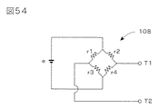
A first strain gauge and a second strain gauge arranged on the front side surface and the back side surface in the vicinity of the first connection end with respect to the connecting portion, respectively, and the front side in the vicinity of the second connection end with respect to the connecting portion; A third strain gauge and a fourth strain gauge disposed on the surface and the back surface, respectively,
The detection circuit detects a bridge voltage of a bridge circuit having the first strain gauge and the fourth strain gauge as the first opposite sides and the second strain gauge and the third strain gauge as the second opposite sides. It is what I did.
本発明に係るトルクセンサでは、回転軸が挿通する貫通開口部を有する環状変形体を利用してトルク検出が行われる。この環状変形体の左右両脇には、左側支持体と右側支持体とが配置され、それぞれが異なる接続点に接合される。このため、一方の支持体に負荷がかかった状態で、他方の支持体にトルクが加わると、環状変形体に歪みが生じることになる。この環状変形体の所定箇所には検出部が設けられており、この検出部は、検出対象となるトルクの作用により弾性変形を生じる一対の変形部と、これら一対の変形部の弾性変形により変位を生じる変位部と、を有している。トルクが作用すると、変位部に変位が生じ、右側支持体に対する距離が変化する。本発明では、この距離の変化を容量素子の静電容量値によって検出できる。すなわち、変位部に固定された変位電極と、この変位電極に対向する位置に配置され右側支持体に固定された固定電極と、によって構成される容量素子の静電容量値の変動量に基づいて、環状変形体の変形態様を認識することができ、作用したトルクの検出が可能になる。
環状変形体、左側支持体、右側支持体は、軸方向の厚みが小さな扁平構造体によって構成することができるので、センサ全体の軸長を短く設定することが可能になる。また、環状変形体の検出部の歪みによってトルク検出が行われるので、検出部としては、弾性変形を生じる材質を用いる必要があるものの、環状変形体としては、比較的高い剛性をもった材質を利用しても、高精度の検出が可能になる。更に、環状変形体の形状の歪みは、変位部に固定された変位電極と、これに対向するように右側支持体に固定された固定電極と、によって構成された容量素子によって検出できるので、構造も単純化され、固定電極の位置調整も容易に行うことができる。このため、小型で高剛性をもち、高い生産効率が実現可能なトルクセンサを提供することが可能になる。
特に、環状変形体の上下の2箇所を左側支持体に接合し、左右の2箇所を右側支持体に接合して、各接続点が90°ずつずれるようにすれば、トルクの作用によって、環状変形体を効率的に変形させることができる。各接続点が45°ずつずれるようにして、4箇所を左側支持体に接合し、4箇所を右側支持体に接合するようにしても同様である。
また、同じトルクが作用した場合に、電極間隔が広がる容量素子と電極間隔が狭まる容量素子とを用いて、両静電容量値の差分として、作用したトルクを検出するようにすれば、同相ノイズやゼロ点ドリフトを抑えた安定したトルク検出が可能になる。温度による各部の膨張の影響を相殺して、精度の高い検出値を得るのにも貢献できる。更に、他軸成分の干渉を排除した正確な検出値を得ることもできる。
本発明に係るトルクセンサでは、環状変形体だけでなく、左側支持体および右側支持体にも、回転軸を挿通する貫通開口部を形成することが可能である。これにより、回転軸に沿って、左側支持体、環状変形体、右側支持体の各貫通開口部を貫く挿通孔を確保することができ、内部が中空となる構造を採ることができる。したがって、本発明に係るトルクセンサを、ロボットアームの関節部分に組み込んで利用する場合、この中空部分に減速機などを配置することができ、総合的に省スペースのロボットアームを設計することが可能になる。
また、環状変形体の連結部の右側の側面と右側支持体の対向面との間に、補助接続部材を設けるようにすれば、検出対象となる所定の回転軸まわりのトルク(回転モーメント)以外の干渉成分の影響を抑制することが可能になるので、他軸成分の干渉に起因する誤差を低減し、より精度の高い検出が可能になる。
なお、左側支持体および右側支持体の代わりに、作用支持体および固定支持体を用いるようにし、固定支持体を、右側支持体と同様に環状変形体の右側に配置し、作用支持体を、環状変形体の外側もしくは内側に配置するようにしても、ほぼ同様の効果が得られる。In the torque sensor according to the present invention, torque detection is performed using an annular deformable body having a through opening through which the rotating shaft is inserted. On the left and right sides of the annular deformable body, a left side support body and a right side support body are disposed, and are joined to different connection points. For this reason, when a torque is applied to the other support body in a state where a load is applied to one support body, the annular deformation body is distorted. A detector is provided at a predetermined location of the annular deformable body. The detector is displaced by a pair of deformable portions that generate elastic deformation by the action of torque to be detected, and by the elastic deformation of the pair of deformable portions. And a displacement portion that generates When torque acts, displacement occurs in the displacement portion, and the distance to the right support changes. In the present invention, this change in distance can be detected by the capacitance value of the capacitive element. That is, based on the variation amount of the capacitance value of the capacitive element constituted by the displacement electrode fixed to the displacement portion and the fixed electrode arranged at a position facing the displacement electrode and fixed to the right support. The deformation mode of the annular deformation body can be recognized, and the applied torque can be detected.
Since the annular deformable body, the left side support body, and the right side support body can be configured by a flat structure having a small axial thickness, the axial length of the entire sensor can be set short. In addition, since torque is detected by the distortion of the detecting portion of the annular deformable body, it is necessary to use a material that causes elastic deformation as the detecting portion, but the annular deformable member is made of a material having relatively high rigidity. Even if it is used, highly accurate detection is possible. Further, the distortion of the shape of the annular deformable body can be detected by a capacitive element constituted by a displacement electrode fixed to the displacement portion and a fixed electrode fixed to the right support so as to be opposed thereto. The position of the fixed electrode can be easily adjusted. For this reason, it is possible to provide a torque sensor that is small in size and has high rigidity and can realize high production efficiency.
In particular, if the two upper and lower portions of the annular deformable body are joined to the left support, and the two left and right locations are joined to the right support so that each connection point is shifted by 90 °, the ring will be The deformable body can be efficiently deformed. The same is true if the four connection points are joined to the left side support and the four points are joined to the right side support so that each connection point is shifted by 45 °.
In addition, when the same torque is applied, if the applied torque is detected as a difference between both capacitance values using a capacitive element with a wide electrode gap and a capacitive element with a narrow electrode gap, the common-mode noise is detected. And stable torque detection with reduced zero point drift. It can contribute to obtaining a highly accurate detection value by offsetting the influence of expansion of each part due to temperature. Furthermore, it is possible to obtain an accurate detection value that eliminates interference of other axis components.
In the torque sensor according to the present invention, it is possible to form a through opening through which the rotation shaft is inserted not only in the annular deformable body but also in the left side support body and the right side support body. Thereby, along the rotation axis, it is possible to secure an insertion hole penetrating each through-opening portion of the left side support body, the annular deformation body, and the right side support body, and it is possible to adopt a structure in which the inside is hollow. Therefore, when the torque sensor according to the present invention is incorporated in a joint part of a robot arm and used, a reduction gear or the like can be arranged in the hollow part, and a space-saving robot arm can be designed comprehensively. become.
Further, if an auxiliary connecting member is provided between the right side surface of the connecting portion of the annular deformable body and the opposing surface of the right support body, other than the torque (rotational moment) around the predetermined rotation axis to be detected. Therefore, it is possible to reduce the error due to the interference of the other axis component and to detect with higher accuracy.
Instead of the left side support and the right side support, a working support and a stationary support are used, and the stationary support is arranged on the right side of the annular deformed body in the same manner as the right side support. Even if it is arranged outside or inside the annular deformation body, substantially the same effect can be obtained.
図1は、先願トルクセンサの基本構造部の分解斜視図である。
図2は、図1に示す3つの構成要素を相互に接合することにより得られる先願トルクセンサの基本構造部の側面図である。
図3は、図2に示す基本構造部をYZ平面で切断した側断面図である。
図4は、図1に示す左側支持体10および凸状部11,12を図1の右方向から見た正面図である。
図5は、図1に示す環状変形体30を図1の右方向から見た正面図である。
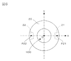
図6は、図1に示す右側支持体20および凸状部21,22を図1の右方向から見た正面図である。
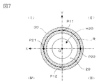
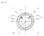
図7は、図2に示す基本構造部をXY平面で切断し、図2の左方向から見た断面図である。
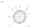
図8は、図2に示す基本構造部にZ軸正まわりのトルクが作用したときの変形状態を示すXY平面での断面図である(図2に示す基本構造部をXY平面で切断し、図2の左方向から見た断面図である。破線は変形前の状態を示す)。
図9は、内周面に変位電極E31,E32を形成した状態の環状変形体30を、図2の左方向から見た平面図である。
図10は、固定電極E21,E22を取り付けた状態の右側支持体20を、図2の左方向から見た平面図である。
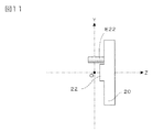
図11は、図10に示す右側支持体20の側面図である。
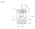
図12は、図3に示す基本構造部に変位電極および固定電極を付加した構造体をVZ平面で切断した側断面図である(図12の上方は、図9および図10に示すV軸方向)。
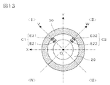
図13は、図2に示す基本構造部に上述した変位電極および固定電極を付加した構造体をXY平面で切断し、図2の左方向から見た断面図である。
図14は、図13に示す基本構造部に対して、Z軸正まわりのトルクが作用したときの状態を示す断面図である(破線は変形前の状態を示す)。
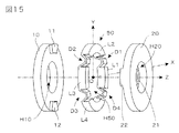
図15は、本発明の基本的実施形態に係るトルクセンサの基本構造部の分解斜視図である。
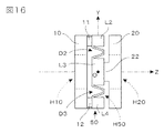
図16は、図15に示す3つの構成要素を相互に接合することにより得られる本発明の基本的実施形態に係るトルクセンサの基本構造部の側面図である。
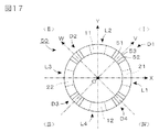
図17は、図15に示す環状変形体50を図15の右方向から見た正面図である。
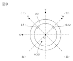
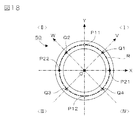
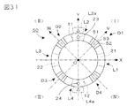
図18は、図15に示す環状変形体50の各検出点および各接続点の配置を示すXY平面上への投影図(右側支持体20側から見た図:環状変形体50は輪郭のみを示す)である。
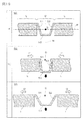
図19は、図15に示す環状変形体50の検出部D1〜D4(代表して符号Dで示す)の詳細構造を示す部分断面図である。
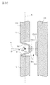
図20は、図15に示す環状変形体50の検出部D1〜D4(代表して符号Dで示す)およびこれに対向する右側支持体20の所定部分に電極を設けた詳細構造を示す部分断面図である。
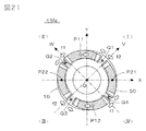
図21は、図15に示す基本構造部における左側支持体10に、Z軸正まわりのトルク+Mzが作用したときの変形状態を示すXY平面での断面図である(図15に示す基本構造部をXY平面で切断し、図15の右方向から見た断面図である。破線は変形前の状態を示す)。
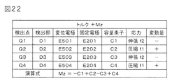
図22は、図21に示す変形が生じたときの各検出部の挙動を示す表である。
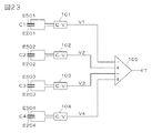
図23は、図15に示す基本的実施形態に係るトルクセンサに用いる検出回路の一例を示す回路図である。
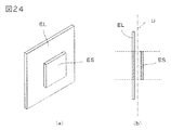
図24は、固定電極に対する変位電極の相対位置が変化した場合にも、容量素子の実効面積を一定に維持する原理を示す図である。
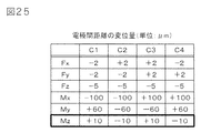
図25は、図16に示す基本構造部における左側支持体10に、各軸方向の力もしくは各軸まわりのモーメントが作用したときの各容量素子の電極間距離の具体的な変位量の実例を示す表である。
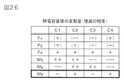
図26は、図25に示す表に基づいて作成した各容量素子の静電容量値の変動量(増減の程度)を示す表である。
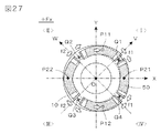
図27は、図15に示す基本構造部における左側支持体10に、X軸正方向の力+Fxが作用したときの変形状態を示すXY平面での断面図である(図15に示す基本構造部をXY平面で切断し、図15の右方向から見た断面図である。破線は変形前の状態を示す)。
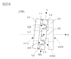
図28は、図15に示す基本構造部における左側支持体10に、X軸正まわりのモーメント+Mxが作用したときの変形状態を示す側面図である。
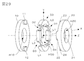
図29は、補助接続部材を付加した本発明の変形例に係るトルクセンサの基本構造部の分解斜視図である。
図30は、図29に示す3つの構成要素を相互に接合することにより得られるトルクセンサの基本構造部の側面図である。
図31は、図29に示す環状変形体50に補助接続部材23,24を接合した状態を、図29の右方向から見た正面図である。
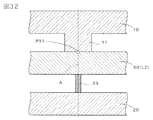
図32は、図29に示す基本構造部における補助接続部材23の近傍構造を示す部分断面図である。
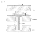
図33は、図32に示す補助接続部材の近傍構造の変形例を示す部分断面図である。
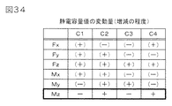
図34は、図29に示す補助接続部材を付加した変形例における左側支持体10に、各軸方向の力もしくは各軸まわりのモーメントが作用したときの各容量素子の静電容量値の変動量(増減の程度)を示す表である。
図35は、8組の検出部を用いる本発明の変形例に係るトルクセンサの環状変形体60の正面図(右側支持体20側から見た図)である。
図36は、図35に示す環状変形体60の検出部および連結部の配置を示す平面図である(ハッチングは、検出部の領域を示すものであり、断面を示すものではない)。
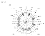
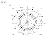
図37は、図35に示す環状変形体60の各検出点および各接続点の配置を示すXY平面上への投影図(右側支持体20側から見た図:環状変形体60は輪郭のみを示す)である。
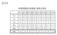
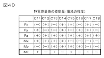
図38は、図35に示す8組の検出部を用いる変形例における左側支持体10に、各軸方向の力もしくは各軸まわりのモーメントが作用したときの各容量素子の静電容量値の変動量(増減の程度)を示す表である。
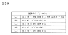
図39は、図35に示す8組の検出部を用いる変形例において、Z軸まわりのモーメントMz(検出対象となるトルク)を算出するための式のバリエーションを示す図である。
図40は、図35に示す8組の検出部を用いる変形例に、更に、補助接続部材を付加したトルクセンサにおける左側支持体10に、各軸方向の力もしくは各軸まわりのモーメントが作用したときの各容量素子の静電容量値の変動量(増減の程度)を示す表である。
図41は、本発明における検出部の構造のバリエーションを示す部分断面図である。
図42は、本発明に利用可能な正方形状の環状変形体60Sの正面図(右側支持体20側から見た図)である。
図43は、図42に示す正方形状の環状変形体60Sの検出部および連結部の配置を示す平面図である(ハッチングは、検出部の領域を示すものであり、断面を示すものではない)。
図44は、図43に示す正方形状の環状変形体60Sの各検出点および各接続点の配置を示すXY平面上への投影図(右側支持体20側から見た図:環状変形体60Sは輪郭のみを示す)である。
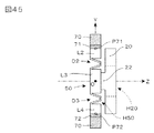
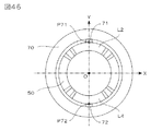
図45は、環状変形体50を作用支持体70によって外側から支持する変形例の基本構造部の側面図(作用支持体70の部分は断面を示す)である。
図46は、図45に示す環状変形体50および作用支持体70を図45の右方向から見た正面図である。
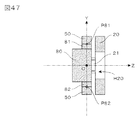
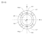
図47は、環状変形体50を作用支持体80によって内側から支持する変形例の基本構造部をYZ平面で切断した側断面図である。
図48は、図47に示す環状変形体50および作用支持体80を図47の右方向から見た正面図である。
図49は、図35に示す環状変形体60を作用支持体70によって外側から支持した状態を右方向からみた正面図である。
図50は、図35に示す環状変形体60を作用支持体80によって内側から支持した状態を右方向からみた正面図である。
図51は、変位部93が外側を向くように配置された検出部D1’〜D4’を有する環状変形体90およびその外側に配置された作用支持体70を示す平面図(上段の図)およびこれらに固定支持体120を付加することにより構成される基本構造部をXZ平面で切断した側断面図(下段の図)である。
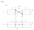
図52は、より単純な構造をもった検出部DDを構成する板状変形部41の弾性変形の態様を示す部分断面図である。
図53は、図52(a)示す検出部DDに生じた弾性変形を検出する検出素子としてストレインゲージを用いた例を示す側面図(図(a))および平面図(図(b))である。
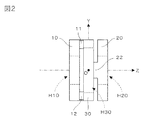
図54は、図53に示す4組のストレインゲージの検出結果に基づいて電気信号を出力するブリッジ回路を示す回路図である。FIG. 1 is an exploded perspective view of the basic structure of the prior application torque sensor.
FIG. 2 is a side view of the basic structure of the prior application torque sensor obtained by joining the three components shown in FIG. 1 to each other.
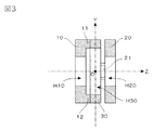
FIG. 3 is a side sectional view of the basic structure shown in FIG. 2 cut along the YZ plane.
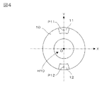
4 is a front view of the
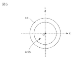
FIG. 5 is a front view of the
6 is a front view of the
FIG. 7 is a cross-sectional view of the basic structure shown in FIG. 2 taken along the XY plane and viewed from the left in FIG.
FIG. 8 is a cross-sectional view in the XY plane showing a deformation state when a torque around the Z-axis is applied to the basic structure shown in FIG. 2 (the basic structure shown in FIG. 2 is cut along the XY plane, It is sectional drawing seen from the left direction of FIG 2. The broken line shows the state before a deformation | transformation.
FIG. 9 is a plan view of the
10 is a plan view of the
FIG. 11 is a side view of the
12 is a side sectional view of the basic structure shown in FIG. 3 in which a displacement electrode and a fixed electrode are added, cut along the VZ plane (the upper part of FIG. 12 is the direction of the V-axis shown in FIGS. 9 and 10). ).
FIG. 13 is a cross-sectional view of the basic structure shown in FIG. 2 in which the above-described displacement electrode and fixed electrode are added, cut along the XY plane and viewed from the left in FIG.
FIG. 14 is a cross-sectional view showing a state when a torque around the Z-axis is applied to the basic structure shown in FIG. 13 (the broken line shows a state before deformation).
FIG. 15 is an exploded perspective view of the basic structure of the torque sensor according to the basic embodiment of the present invention.
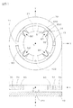
FIG. 16 is a side view of the basic structure portion of the torque sensor according to the basic embodiment of the present invention obtained by joining the three components shown in FIG. 15 to each other.
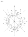
FIG. 17 is a front view of the annular
18 is a projection view on the XY plane showing the arrangement of the detection points and connection points of the annular
FIG. 19 is a partial cross-sectional view illustrating a detailed structure of the detection units D1 to D4 (represented by a symbol D) of the
FIG. 20 is a partial cross-sectional view showing a detailed structure in which electrodes are provided on predetermined portions of the detection portions D1 to D4 (represented by reference numeral D) of the annular
FIG. 21 is a cross-sectional view on the XY plane showing a deformation state when a torque + Mz around the Z-axis is applied to the
FIG. 22 is a table showing the behavior of each detection unit when the deformation shown in FIG. 21 occurs.
FIG. 23 is a circuit diagram showing an example of a detection circuit used in the torque sensor according to the basic embodiment shown in FIG.
FIG. 24 is a diagram illustrating the principle of maintaining the effective area of the capacitive element constant even when the relative position of the displacement electrode with respect to the fixed electrode changes.
FIG. 25 shows an example of a specific amount of displacement of the distance between the electrodes of each capacitive element when a force in each axial direction or a moment about each axis is applied to the
FIG. 26 is a table showing the fluctuation amount (degree of increase / decrease) of the capacitance value of each capacitive element created based on the table shown in FIG.
27 is a cross-sectional view on the XY plane showing a deformation state when a force + Fx in the positive X-axis direction is applied to the
FIG. 28 is a side view showing a deformed state when a moment + Mx about the positive X-axis acts on the
FIG. 29 is an exploded perspective view of a basic structure portion of a torque sensor according to a modification of the present invention to which an auxiliary connecting member is added.
FIG. 30 is a side view of the basic structure of the torque sensor obtained by joining the three components shown in FIG. 29 to each other.
31 is a front view of the annular
FIG. 32 is a partial cross-sectional view showing a structure in the vicinity of the auxiliary connecting
FIG. 33 is a partial cross-sectional view showing a modification of the vicinity structure of the auxiliary connecting member shown in FIG.
FIG. 34 shows the amount of change in the capacitance value of each capacitive element when a force in each axial direction or a moment about each axis is applied to the
FIG. 35 is a front view (viewed from the
FIG. 36 is a plan view showing the arrangement of the detection part and the connection part of the annular
FIG. 37 is a projection view on the XY plane showing the arrangement of the detection points and connection points of the annular
FIG. 38 shows the variation in the capacitance value of each capacitive element when a force in the direction of each axis or a moment about each axis is applied to the
FIG. 39 is a diagram showing variations of an equation for calculating a moment Mz (torque to be detected) about the Z axis in a modification using the eight detection units shown in FIG.
In FIG. 40, in the modification using the eight detection units shown in FIG. 35, a force in each axial direction or a moment around each axis is applied to the
FIG. 41 is a partial cross-sectional view showing a variation of the structure of the detection unit in the present invention.
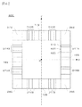
FIG. 42 is a front view (viewed from the
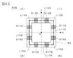
FIG. 43 is a plan view showing the arrangement of the detection part and the connection part of the square annular
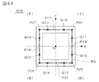
44 is a projection view on the XY plane showing the arrangement of the detection points and connection points of the square annular
FIG. 45 is a side view of a basic structure portion of a modified example in which the annular
46 is a front view of the
FIG. 47 is a side cross-sectional view of a basic structure portion of a modified example in which the annular
48 is a front view of the annular
FIG. 49 is a front view of the
FIG. 50 is a front view of the
FIG. 51 is a plan view (upper view) showing an annular
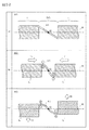
FIG. 52 is a partial cross-sectional view showing a mode of elastic deformation of the plate-
FIG. 53 is a side view (FIG. (A)) and a plan view (FIG. (B)) showing an example in which a strain gauge is used as a detection element for detecting elastic deformation generated in the detection unit DD shown in FIG. 52 (a). is there.
FIG. 54 is a circuit diagram showing a bridge circuit that outputs electrical signals based on the detection results of the four sets of strain gauges shown in FIG.
以下、本発明を図示する実施形態に基づいて説明する。なお、本発明は、前掲の特許文献9(国際公開第WO2012/018031号公報)に開示されている先願トルクセンサを改良した発明である。そこで、説明の便宜上、まず、以下の§1〜§3において、先願トルクセンサについての説明を行い、本発明の特徴については、§4以降で述べることにする。
<<< §1. 先願トルクセンサの基本構造部の特徴 >>>
図1は、先願トルクセンサの基本構造部の分解斜視図である。図示のように、この基本構造部は、左側支持体10と右側支持体20との間に、環状変形体30を配置し、これら3つの構成要素を相互に接合することによって構成される。ここでは、便宜上、図示のとおりXYZ三次元座標系を定義して、以下の説明を行うことにする。ここで、図の水平方向に描かれたZ軸が、検出対象となるトルクの回転軸に相当し、このトルクセンサは、この回転軸まわり(Z軸まわり)のトルクを検出する機能を果たすことになる。
図の中央に配置された環状変形体30は、検出対象となるトルクの作用により弾性変形を生じる材質からなり、その内部には、回転軸(Z軸)が挿通する貫通開口部H30が形成されている。一方、図の左側に配置された左側支持体10は、環状変形体30の左側面を支持する部材であり、図の右側に配置された右側支持体20は、環状変形体30の右側面を支持する部材である。図示する先願トルクセンサの場合、左側支持体10は、回転軸(Z軸)が挿通する貫通開口部H10が形成された環状部材であり、右側支持体20は、回転軸(Z軸)が挿通する貫通開口部H20が形成された環状部材である。
なお、一般に右側および左側という概念は、特定の観察方向から見た場合にのみ意味をもつ概念であるが、ここでは説明の便宜上、図1に示すとおり、回転軸(Z軸)が左右に伸びる水平線をなすような基準観察方向(右方向がZ軸の正方向となるような観察方向)から見たときに、環状変形体30の左側に隣接する位置に配置された支持体を左側支持体10と呼び、環状変形体30の右側に隣接する位置に配置された支持体を右側支持体20と呼ぶことにする。
ここでは、環状変形体30の中心位置にXYZ三次元座標系の原点Oを定義しており、左側支持体10,環状変形体30,右側支持体20は、いずれもZ軸を中心軸とする円環状の部材によって構成されている。より具体的には、環状変形体30は、Z軸(回転軸)を中心軸として配置された円盤の中央部に、より径の小さな同心円盤の形状をした貫通開口部H30を形成することにより得られる円環状の部材からなる。同様に、左側支持体10および右側支持体20も、Z軸(回転軸)を中心軸として配置された円盤の中央部に、より径の小さな同心円盤の形状をした貫通開口部H10,H20を形成することにより得られる円環状の部材からなる。
一方、左側支持体10の右側面には、右方に突出した2つの扇形の凸状部11,12が設けられており、この凸状部11,12の頂面が環状変形体30の左側面に接合されている。図示のとおり、凸状部11は環状変形体30の上部(Y軸正方向に位置する部分)に接合され、凸状部12は環状変形体30の下部(Y軸負方向に位置する部分)に接合される。同様に、右側支持体20の左側面には、左方に突出した2つの扇形の凸状部21,22が設けられており、この凸状部21,22の頂面が環状変形体30の右側面に接合されている。図示のとおり、凸状部21は環状変形体30の奥の部分(X軸正方向に位置する部分)に接合され、凸状部22は環状変形体30の手前の部分(X軸負方向に位置する部分)に接合される。
図2は、図1に示す3つの構成要素を相互に接合することにより得られるトルクセンサの基本構造部の側面図であり、図3は、この基本構造部をYZ平面で切断した側断面図である。ここに示す例の場合、図3に示すとおり、凸状部11,12は、左側支持体10と一体となった構造体であり、その頂面が環状変形体30の左側面に接合されている。同様に、凸状部21,22は、右側支持体20と一体となった構造体であり、その頂面が環状変形体30の右側面に接合されている。
結局、凸状部11,12は、環状変形体30の左側支持体10に対向する左側の側面上の左側接続点を、左側支持体10に接続する左側接続部材として機能し、凸状部21,22は、環状変形体30の右側支持体20に対向する右側の側面上の右側接続点を、右側支持体20に接続する右側接続部材として機能する。
図4は、左側支持体10および凸状部11,12を図1の右方向から見た正面図、図5は、環状変形体30を図1の右方向から見た正面図、図6は、右側支持体20および凸状部21,22を図1の右方向から見た正面図である。図4において、凸状部11,12の中心位置に白ドットで示されている点P11,P12は左側接続点であり、§2において、環状変形体30に対する接続位置を説明するために用いられる。同様に、図6において、凸状部21,22の中心位置に黒ドットで示されている点P21,P22は右側接続点であり、やはり§2において、環状変形体30に対する接続位置を説明するために用いられる。
なお、図4に示す部品(左側支持体10および凸状部11,12)と図6に示す部品(右側支持体20および凸状部21,22)とは、実際には、全く同一のものにするのが好ましい。この場合、図4に示す部品をY軸を回転軸として180°回転させて裏返し、更に、Z軸を回転軸として90°回転させれば、図6に示す部品に完全に一致する。したがって、実際には、図4に示す部品を2組用意し、図5に示す部品を1組用意すれば、図2に示す基本構造部を構成することができる。
図5に示すとおり、環状変形体30には、円形の貫通開口部H30が設けられているが、これは、検出に必要な弾性変形を生じさせるためのものである。後述するように、この基本構造部に検出対象となるトルクが作用した場合、環状変形体30は楕円形に変形する必要がある。このような環状変形体30の弾性変形のしやすさは、センサの検出感度を左右するパラメータになる。弾性変形しやすい環状変形体30を用いれば、微小なトルクでも検出可能な感度の高いセンサを実現することができるが、検出可能なトルクの最大値は抑制されることになる。逆に、弾性変形しにくい環状変形体30を用いれば、検出可能なトルクの最大値を大きくとることができるが、感度は低下するため、微小なトルクの検出はできなくなる。
環状変形体30の弾性変形のしやすさは、Z軸方向の厚み(薄くするほど弾性変形しやすい)および貫通開口部H30の径(大きくするほど弾性変形しやすい)に依存して決まり、更に、その材質にも依存して決まる。したがって、実用上は、トルクセンサの用途に応じて、環状変形体30の各部の寸法や材質を適宜選択すればよい。
一方、左側支持体10および右側支持体20は、トルクを検出する原理上、弾性変形を生じる部材である必要はない。むしろ、作用したトルクが環状変形体30の変形に100%寄与するようにするためには、左側支持体10および右側支持体20は、完全な剛体である方が好ましい。図示の例において、左側支持体10および右側支持体20として、中心部に貫通開口部H10,H20を有する環状の構造体を用いた理由は、弾性変形しやすくするためではなく、回転軸(Z軸)に沿って、左側支持体10、環状変形体30、右側支持体20の各貫通開口部H10,H30,H20を貫く挿通孔が確保されるようにするためである。
図3の側断面図を見れば明らかなように、この基本構造部は、内部が中空となる構造を採っている。このような中空部分を有するトルクセンサを、ロボットアームの関節部分に組み込んで利用する場合、この中空部分に減速機などを配置することができ、総合的に省スペースのロボットアームを設計することが可能になる。これは、中実丸棒形状をしたトーションバーのねじれを利用する従来型のトルクセンサでは実現困難であった利点のひとつである。
このように、先願トルクセンサでは、環状変形体30は、トルク検出に必要な程度の弾性変形を生じる材質で構成する必要があるが、左側支持体10および右側支持体20は、弾性変形を生じる必要はなく、むしろ剛性の高い材質を用いて構成するのが好ましい。実用上、左側支持体10,右側支持体20,環状変形体30の材料としては、絶縁材料を利用するのであれば、プラスチックなどの合成樹脂を用いれば十分であり、導電材料を利用するのであれば(この場合、後述するように、電極が短絡しないよう必要箇所に絶縁を施す必要がある)、ステンレス、アルミニウムなどの金属を用いれば十分である。もちろん、絶縁材料と導電材料とを組み合わせて利用してもかまわない。
左側支持体10、右側支持体20、環状変形体30は、いずれも軸方向の厚みが小さな扁平構造体によって構成することができるので、センサ全体の軸長を短く設定することが可能になる。また、環状変形体30の形状の歪みによってトルク検出が行われるので、環状変形体30としては、弾性変形を生じる材質を用いる必要があるものの、比較的高い剛性をもった材質を利用しても、高精度の検出が可能になる。
<<< §2. 先願トルクセンサにおけるトルクの検出原理 >>>
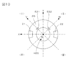
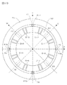
続いて、ここでは、§1で述べた先願トルクセンサの基本構造部にトルクが作用した場合、各部がどのように変形するかを考えてみる。図7は、図2に示す基本構造部をXY平面で切断し、図2の左方向から見た断面図である。なお、この図7に示されたXY座標系は、通常のXY座標系を裏側から見たものになる(X軸正方向は図の左方向になる)。したがって、このXY座標系では、左上領域が第1象限、右上領域が第2象限、右下領域が第3象限、左下領域が第4象限になる。図示のI〜IVは、この座標系の各象限を示すものである。図にハッチングを施した断面部分は、環状変形体30の部分に相当し、その奥に、右側支持体20が見えている。図の点P11〜P22は、図4および図6に示した各接続点P11〜P22のXY平面上への正射影投影像である。
すなわち、図7において、Y軸上に配置された白ドットで示されている点P11,P12は、左側支持体10の凸状部11,12の接合位置(接合面の中心点)を示しており、X軸上に配置された黒ドットで示されている点P21,P22は、右側支持体20の凸状部21,22の接合位置(接合面の中心点)を示している。結局、環状変形体30の左側面は、Y軸に沿った2箇所の接続点P11,P12において左側支持体10に接合され、環状変形体30の右側面は、X軸に沿った2箇所の接続点P21,P22において右側支持体20に接合されていることになる。
図示の例の場合、各接続点P11,P12,P21,P22は、図に一点鎖線で示す基本環状路R(XY平面上において環状変形体30の内周円と外周円との中間に位置する円)上に位置している。このように、環状変形体30の上下の2箇所を左側支持体10に接合し、左右の2箇所を右側支持体20に接合して、各接続点が90°ずつずれるようにすれば、トルクの作用によって、環状変形体30を効率的に変形させることができる。
図7に示す例の場合、環状変形体30の両側面をXY平面上に投影して正射影投影像を得た場合に、第1の右側接続点P21の投影像が正のX軸上、第2の右側接続点P22の投影像が負のX軸上、第1の左側接続点P11の投影像が正のY軸上、第2の左側接続点P12の投影像が負のY軸上に配置されていることになる。このような配置を行うと、環状変形体30を軸対称性をもった楕円に変形させることができるので、軸対称性をもった検出値を得ることができる。
先願トルクセンサ(本発明に係るトルクセンサも同様)は、図2に示す基本構造部において、左側支持体10と右側支持体20との間に相対的に加わるトルク(回転モーメント)を検出するものであり、検出値は、両支持体10,20間に相対的に作用する力を示すものである。そこで、ここでは説明の便宜上、右側支持体20に負荷がかかった状態において、左側支持体10に加わった回転モーメントを検出対象となるトルクとして考えることにする(もちろん、左側支持体10に負荷がかかった状態において、右側支持体20に加わった回転モーメントを検出対象となるトルクとしても等価である。)。
たとえば、ロボットアームの関節部分にこのトルクセンサを利用した一例として、左側支持体10にモータなどの駆動源を取り付け、右側支持体20にロボットハンドを取り付けた例を考えてみよう。ロボットハンドに重量のある物体が把持されている状態で、駆動源から左側支持体10に対して回転駆動力を加えたとすると、この回転駆動力が関節部分を構成する基本構造部を介して、ロボットハンド側へと伝達されることになる。この場合、右側支持体20を回転駆動させようとするトルクが作用することになり、当該トルクは、右側支持体20を固定した状態において、左側支持体10に加わった回転モーメントに相当する。
さて、このような回転モーメントが、図7に示す構造体にどのような変化をもたらすかを考えてみる。右側支持体20を固定すると、図7に示すX軸上の接続点P21,P22(黒ドット)の位置は固定状態となる。一方、左側支持体10に対して、たとえば、図7において時計まわりの方向に回転モーメントが加わったとすると、Y軸上の接続点P11,P12(白ドット)は時計まわりに移動しようとする。そうなると、必然的に、第1象限Iに位置する円弧P21−P11の部分は内側方向に縮み、第2象限IIに位置する円弧P11−P22の部分は外側に膨らみ、第3象限IIIに位置する円弧P22−P12の部分は内側方向に縮み、第4象限IVに位置する円弧P12−P21の部分は外側に膨らむことになる。
図8は、図7に示す構造体に、このような変形が生じた状態を示す断面図である。すなわち、図2に示す基本構造部にZ軸正まわりのトルクが作用した場合に、この基本構造部をXY平面で切断し、図2の左方向から見た断面図である。なお、本願では、任意の座標軸に関して、右ねじを当該座標軸の正方向に進めるための回転方向を正方向と定義し、右ねじを当該座標軸の負方向に進めるための回転方向を負方向と定義している。したがって、図8において、Z軸正まわりのトルクは、図に白抜き矢印で示すとおり時計まわりの方向に作用するトルクということになる。
図8に描かれた破線は、環状変形体30の変形前の状態(図7の状態)を示している。この破線を参考にすれば、Z軸正まわりのトルクが作用したことにより、環状変形体30は楕円形に変形していることが容易に把握できよう。ここでは、説明の便宜上、XY平面上に、原点Oを通りX軸およびY軸に対して45°をなすV軸およびW軸を定義する。V軸は第1象限Iを正方向とする座標軸であり、W軸は第2象限IIを正方向とする座標軸である。図示のとおり、環状変形体30は、V軸を短軸方向、W軸を長軸方向とする楕円に変形しており、V軸およびW軸に対して軸対称性を有している。このような軸対称性は、§3で述べる方法でトルクの検出値を得る場合に好都合である。
図示の実施形態において、軸対称性をもった変形が生じるのは、図7に示すとおり、無負荷時(トルクが作用していない時)に環状変形体30が完全な円形をしており、環状変形体30の両側面をXY平面上に投影して正射影投影像を得た場合に、第1の右側接続点P21の投影像が正のX軸上、第2の右側接続点P22の投影像が負のX軸上、第1の左側接続点P11の投影像が正のY軸上、第2の左側接続点P12の投影像が負のY軸上に配置されているためである。
作用したトルクが大きければ大きいほど、環状変形体30はより扁平した楕円に変形することになる。したがって、図8において、環状変形体30のV軸上に位置する部分の原点Oからの距離や、環状変形体30のW軸上に位置する部分の原点Oからの距離を測定することができれば(これらの距離は、破線で示す変形前の位置からの変位量を示す情報になる)、作用したトルクの大きさを求めることができる。別言すれば、環状変形体30の内周面もしくは外周面の径方向の変位を測定することができればよい。
一方、逆向きにトルクが作用した場合、すなわち、Z軸負まわりのトルクが作用した場合は、図8に示す例とは逆に、環状変形体30(の接続点P11,P12)に対して反時計まわりの回転力が作用するため、環状変形体30は、V軸を長軸方向、W軸を短軸方向とする楕円に変形する。したがって、環状変形体30のV軸上に位置する部分あるいはW軸上に位置する部分の変位方向は、図8に示す例とは逆の方向になる。
結局、先願トルクセンサの場合、環状変形体30のV軸上に位置する部分あるいはW軸上に位置する部分の変位を測定すれば、作用したトルクの方向および大きさの双方を検出することが可能になる。たとえば、環状変形体30の内周面とV軸との交点の位置をモニタした場合、破線で示す基準位置から内側方向に変位した場合はZ軸正まわりのトルクが加わっており、外側方向に変位した場合はZ軸負まわりのトルクが加わっていると判断できる。あるいは、環状変形体30の内周面とW軸との交点の位置をモニタした場合、破線で示す基準位置から外側方向に変位した場合はZ軸正まわりのトルクが加わっており、内側方向に変位した場合はZ軸負まわりのトルクが加わっていると判断できる。もちろん、変位量の絶対値は、作用したトルクの大きさを示すものになる。
この先願トルクセンサにおいて生じる環状変形体30の径方向の変位は、環状変形体30に生じたねじれ角度が小さくても、環状変形体の径次第で比較的大きな変位になる。このため、比較的剛性が高い環状変形体30を用いたとしても、十分な感度をもったトルク検出が可能になる。
以上が、先願トルクセンサにおけるトルクの検出原理である。先願トルクセンサでは、このような原理に基づくトルク検出を行うために、これまで述べてきた基本構造部に、更に、容量素子と検出回路とを付加することになる。
<<< §3. 先願トルクセンサにおける容量素子を用いた検出方法 >>>
先願トルクセンサでは、図2に示す基本構造部に、更に、容量素子と検出回路を付加し、トルクセンサを構成することになる。図8に示すように、トルクの作用により、環状変形体30は楕円に変形する。このような変形により、最も大きな変位を生じる部分は、V軸上に位置する部分あるいはW軸上に位置する部分であるから、環状変形体30の特定部分の変位に基づいて、環状変形体30の変形量(作用したトルクの大きさ)を測定するには、V軸上に位置する部分あるいはW軸上に位置する部分の変位を測定するのが最も効率的である。
そこで、先願トルクセンサでは、環状変形体30の内周面のV軸上に位置する部分およびW軸上に位置する部分に変位電極を形成している。図9は、内周面に変位電極E31,E32を形成した状態の環状変形体30を、図2の左方向から見た平面図である。説明の便宜上、X,Y,V,W軸が重ねて描かれている。変位電極E31は、V軸の正の領域と環状変形体30の内周面との交差位置に形成された電極であり、変位電極E32は、W軸の正の領域と環状変形体30の内周面との交差位置に形成された電極である。これら変位電極E31,E32の奥行き寸法(図9の紙面に垂直方向の寸法)は、環状変形体30の奥行き寸法に等しい。この例の場合、変位電極E31,E32は、環状変形体30の内周面に、蒸着やメッキ等の方法で形成された金属膜などの導電層によって構成されている。もちろん、環状変形体30がアルミニウムやステンレスのような金属でできている場合は、環状変形体30自体が導電性をもつため、絶縁層を介して変位電極E31,E32を形成する必要がある。
一方、これら変位電極E31,E32に対向する位置には、それぞれ固定電極E21,E22が設けられ、右側支持体20に固定される。図10は、これら固定電極E21,E22を取り付けた状態の右側支持体20を、図2の左方向から見た平面図である。ここでも、説明の便宜上、X,Y,V,W軸が重ねて描かれている。固定電極E21は、V軸の正の領域に配置され、変位電極E31に対向する。固定電極E22は、W軸の正の領域に配置され、変位電極E32に対向する。
図11は、図10に示す右側支持体20の側面図である。図示のとおり、固定電極E22は、右側支持体20の左側面から回転軸に沿った方向(Z軸負方向)に突き出した導電板によって構成されている。なお、固定電極E21は、固定電極E22の奥に隠れているため、図11には現れていない。
図12は、図3に示す基本構造部に変位電極および固定電極を付加した構造体をVZ平面で切断した側断面図である。図3がYZ平面で切断した側断面図であるのに対して、図12はVZ平面で切断した側断面図であるため、図12の上方は、Y軸方向ではなく、図9および図10に示すV軸方向となっている。この図12の側断面図には、V軸上に配置された変位電極E31と固定電極E21とが互いに対向している状態が明瞭に示されている。変位電極E31は、環状変形体30の内周面に固着された電極であるため、環状変形体30の変形に依存して変位する。一方、固定電極E21は、右端が右側支持体20に固定されており、環状変形体30の変形にかかわらず、常に一定の位置を保つことになる。
結局、変位電極E31の固定電極E21に対する相対位置は、環状変形体30の変形に依存して変化することになる。別言すれば、変位電極E31と固定電極E21との電極間距離は、環状変形体30の変形に依存して変化する。図12には示されていないが、W軸上に配置された変位電極E32と固定電極E22との関係も全く同様である。
図13は、図2に示す基本構造部に上述した変位電極および固定電極を付加した構造体をXY平面で切断し、図2の左方向から見た断面図である。この断面図では、V軸上に配置された変位電極E31と固定電極E21とが互いに対向し、W軸上に配置された変位電極E32と固定電極E22とが互いに対向した状態が明瞭に示されている。
ここに示す例の場合、変位電極E31,E32は、環状変形体30の内周面に形成された導電層によって構成されているため、その表面は環状変形体30の内周に沿った曲面になる。そこで、これらに対向する固定電極E21,E22も、曲面状の電極にしている。別言すれば、変位電極E31,E32や固定電極E21,E22の表面は、Z軸を中心軸とした同心状の円柱表面によって構成されている。もっとも、各電極の表面形状は容量素子を構成する役割を果たすことができれば、どのような形状であってもよいので、表面が平面となる平板状の電極を用いてもかまわない。
なお、本願図面では、図示の便宜上、各変位電極および各固定電極の厚みの実寸を無視して描いてある。たとえば、変位電極E31,E32を、環状変形体30の内周面に形成された導電層(蒸着層やメッキ層)によって構成した場合、その厚みは、数μm程度に設定することができる。これに対して、固定電極E21,E22を、右側支持体20の左側面から突き出した導電板(金属板)によって構成した場合、実用上の強度を確保するために、その厚みは、数mm程度確保するのが好ましい。したがって、図13等では、便宜上、変位電極の厚みと固定電極の厚みを同じ寸法で描いてあるが、これら電極の厚みの実寸は、製造工程や実用上の強度を考慮して、それぞれ適当な値に設定されるべきものである。
図14は、図13に示す基本構造部に対して、Z軸正まわりのトルクが作用したときの状態を示すXY断面図である。§2で述べたとおり、このようなトルクが作用すると、環状変形体30は楕円状に変形し、V軸は当該楕円の短軸方向、W軸は当該楕円の長軸方向になる。その結果、V軸上に配置された一対の電極E21,E31の電極間隔は狭まり、W軸上に配置された一対の電極E22,E32の電極間隔は広がることになる。そこで、一対の電極E21,E31により容量素子C1を構成し、一対の電極E22,E32により容量素子C2を構成しておけば、これら容量素子C1,C2の静電容量値の変動量として、作用したトルクの方向および大きさを検出することが可能になる。
たとえば、図13に示す無負荷状態(トルクが作用していない状態)を基準として、電極E21,E31からなる容量素子C1の静電容量値の変動に着目すると、図14に示すようにZ軸正まわりのトルクが作用すると、電極間隔が狭まるため、静電容量値は増加することになり、逆に、Z軸負まわりのトルクが作用すると、電極間隔が広がるため、静電容量値は減少することになる。したがって、静電容量値の増加変動はZ軸正まわりのトルクが作用していることを示し、静電容量値の減少変動はZ軸負まわりのトルクが作用していることを示すことになる。もちろん、変動量の絶対値は、作用したトルクの大きさを示すことになる。
同様に、電極E22,E32からなる容量素子C2の静電容量値の変動に着目すると、図14に示すようにZ軸正まわりのトルクが作用すると、電極間隔が広がるため、静電容量値は減少することになり、逆に、Z軸負まわりのトルクが作用すると、電極間隔が狭まるため、静電容量値は増加することになる。したがって、静電容量値の減少変動はZ軸正まわりのトルクが作用していることを示し、静電容量値の増加変動はZ軸負まわりのトルクが作用していることを示すことになる。もちろん、変動量の絶対値は、作用したトルクの大きさを示すことになる。
結局、容量素子C1を用いても、容量素子C2を用いても、Z軸まわりのトルク検出が可能であり、理論的には、いずれか一方の容量素子のみを用いれば足りる。ただ、実用上は、容量素子C1,C2の双方を用いた検出を行うのが好ましい。すなわち、環状変形部30が楕円に変形した際の短軸位置(V軸上)と長軸位置(W軸上)とにそれぞれ容量素子C1,C2を設けておけば、同一のトルクが加わった場合、短軸位置(V軸上)では電極間隔が狭まり静電容量値が増加するのに対して、長軸位置(W軸上)では電極間隔が広がり静電容量値が減少するので、両静電容量値C1,C2の差分として、作用したトルクを検出することができる。このような差分検出は、同相ノイズやゼロ点ドリフトを抑えた安定したトルク検出に有効であり、また、温度による各部の膨張の影響を相殺して、精度の高い検出値を得るのに貢献する。
このような差分検出を行うためには、要するに、環状変形体30の各部分のうち、所定回転方向のトルクが作用したときに、回転軸に近づく方向に変位する第1の部分(この例ではV軸との交差部分)に固定された第1の変位電極E31と、回転軸から離れる方向に変位する第2の部分(この例ではW軸との交差部分)に固定された第2の変位電極E32と、第1の変位電極E31に対向する位置に配置された第1の固定電極E21と、第2の変位電極E32に対向する位置に配置された第2の固定電極E22と、を設けておけばよい。
そして、このような差分検出を行うための検出回路として、第1の変位電極E31と第1の固定電極E21とによって構成される第1の容量素子C1の静電容量値と、第2の変位電極E32と第2の固定電極E22とによって構成される第2の容量素子C2の静電容量値と、の差に相当する電気信号を、作用したトルクを示す電気信号として出力する回路を設けておけばよい。
このように、先願トルクセンサは、図1に示すような単純な基本構造部に、変位電極および固定電極を付加することにより構成することができるため、小型で高剛性をもったセンサを実現することができる。しかしながら、商業的量産を行う上では、固定電極の取り付けおよびその位置調整に多大な作業負担が必要になり、生産効率が低下し、コストが高騰するという問題がある。
たとえば、図10に示す例の場合、固定電極E21,E22は、右側支持体20に取り付けられるが、環状変形体30の内周面に取り付けられた変位電極E31,E32に対応する位置に配置する必要がある。すなわち、実際には、図11に示すように、固定電極E22は、右側支持体20の左側面から垂直左方へと突き出すように取り付け、対向する両電極が平行になるように調整する必要がある(図示の例の場合、右側支持体20の左側面に対して正確に90°をなすように取り付ける必要がある。)。したがって、固定電極E22の根端部を右側支持体20に正確に固定するためには、それなりに手間のかかる工程が必要になる。
また、図12の側断面図を見れば明らかなように、変位電極E31と固定電極E21との間の電極間隔は、固定電極E21の根端部の固定状態によって変動し、当該変動は検出値(容量素子の静電容量値)に影響を及ぼすことになる。このため、商業的量産品を製造する上では、個々の製品ごとに、固定電極E21に対して正確な位置調整を行う必要があり、多大な作業負担が課されることになる。また、上述した差分検出を行うには、複数の容量素子を対称性をもたせて配置し、個々の容量素子についての電極間隔が互いに等しくなるような調整が必要になるので、作業負担は更に増大する。
本発明は、先願トルクセンサにおけるこのような問題を解決するため、より生産効率を高めることができる新たな工夫を提案するものである。以下、本発明を具体的な実施形態に基づいて詳述する。
<<< §4. 本発明の基本的実施形態に係るトルクセンサの基本構造部 >>>
<4−1.基本構造部の全体構成>
図15は、本発明の基本的実施形態に係るトルクセンサの基本構造部の分解斜視図である。図示のように、この基本構造部は、左側支持体10と右側支持体20との間に、環状変形体50を配置し、これら3つの構成要素を相互に接合することによって構成される。ここでも、便宜上、図示のとおりXYZ三次元座標系を定義して、以下の説明を行う。図の水平方向に描かれたZ軸が、検出対象となるトルクの回転軸に相当し、このトルクセンサは、この回転軸まわり(Z軸まわり)のトルクを検出する機能を果たす。
図1に示す先願トルクセンサの基本構造部と、図15に示す本発明に係るトルクセンサの基本構造部との相違は、前者の環状変形体30が、後者では環状変形体50に置き換えられている点である。図1に示す環状変形体30は、Z軸(回転軸)を中心軸として配置された円盤の中央部に、より径の小さな同心円盤の形状をした貫通開口部H30を形成することにより得られる円環状の部材である。これに対して、図15に示す環状変形体50は、この円環状の環状変形体30に対して、部分的な材料除去加工を施すことにより得られた部材であり、内部に形成された貫通開口部H50には、回転軸(Z軸)が挿通している。したがって、この環状変形体50は、基本的には、内部に同心円盤状の貫通開口部H50が形成された円環状の部材であるが、材料除去加工を施した部分によって、図示のような検出部D1〜D4が形成されていることになる。
なお、ここでは、環状変形体50の形状を説明するために「材料除去加工」という文言を用いているが、環状変形体50を実際に作成する際には、必ずしも円環状の部材に対して切削加工などを施す必要はない。たとえば、環状変形体50を金属で構成する場合であれば、鋳型を用いた鋳造によって製造することもでき、プラスチックなどの樹脂で構成する場合であれば、所定の型を用いた射出成形加工やプレス加工によって環状変形体50を製造することができる。
ここでは、環状変形体50のうち、検出部D1〜D4以外の部分を連結部L1〜L4と呼ぶことにする。図示のとおり、環状変形体50は、4組の検出部D1〜D4と4組の連結部L1〜L4とを交互に配置した構造を有する。4組の連結部L1〜L4は、円環状の部材の円弧状部分によって構成され、4組の検出部D1〜D4は、後述するように、トルクの作用による弾性変形が生じる構造を有している。図示の例の場合、環状変形体50の検出部D1〜D4の部分は、肉厚の薄い板状片によって構成されており、この板状片が板ばねとして機能して検出対象となるトルクの作用により弾性変形を生じる。
なお、この図15に示す左側支持体10および右側支持体20は、図1に示す左側支持体10および右側支持体20と全く同一の構成要素であり、Z軸(回転軸)を中心軸として配置された円盤の中央部に、より径の小さな同心円盤の形状をした貫通開口部H10,H20を形成することにより得られる円環状の部材である。結局、この図15に示す基本構造部の場合も、左側支持体10および右側支持体20は、中心部に貫通開口部H10,H20を有する環状の構造体であり、Z軸(回転軸)に沿って、左側支持体10、環状変形体50、右側支持体20の各貫通開口部H10,H50,H20を貫く挿通孔が確保されている。なお、各支持体10,20について貫通開口部H10,H20を形成することは、本発明を実施する上での必須条件ではないので、貫通開口部H10,H20は必ずしも設ける必要はない。
図15に示す基本構造部においても、左側支持体10は、環状変形体50の左側面を支持する部材であり、右側支持体20は、環状変形体50の右側面を支持する部材である。ここでも、環状変形体50の中心位置にXYZ三次元座標系の原点Oを定義しており、左側支持体10,環状変形体50,右側支持体20は、いずれもZ軸が中心軸となるように配置されている。
また、左側支持体10の右側面には、右方に突出した2つの扇形の凸状部11,12(左側接続部材)が設けられており、この凸状部11,12の頂面が環状変形体50の左側面に接合されている。同様に、右側支持体20の左側面には、左方に突出した2つの扇形の凸状部21,22(右側接続部材)が設けられており、この凸状部21,22の頂面が環状変形体50の右側面に接合されている。
図示のとおり、凸状部11は環状変形体50の上部(Y軸正方向に位置する連結部L2)に接合され、凸状部12は環状変形体50の下部(Y軸負方向に位置する連結部L4)に接合される。同様に、凸状部21は環状変形体50の奥の部分(X軸正方向に位置する連結部L1)に接合され、凸状部22は環状変形体50の手前の部分(X軸負方向に位置する連結部L3)に接合される。後述するように、これら各凸状部の接続位置は、環状変形体50の各接続点Q1〜Q4の位置に相当する。
図16は、図15に示す3つの構成要素を相互に接合することにより得られるトルクセンサの基本構造部の側面図である(図が繁雑になるのを避けるため、検出部に関しては、手前に位置する検出部D2,D3の外周面のみを示してある)。ここに示す例の場合、図15に示すとおり、凸状部11,12は、左側支持体10と一体となった構造体であり、その頂面が環状変形体50の連結部L2,L4の左側面に接合されている。同様に、凸状部21,22は、右側支持体20と一体となった構造体であり、その頂面が環状変形体50の連結部L1,L3の右側面に接合されている。
結局、凸状部11,12は、環状変形体50の左側支持体10に対向する左側の側面上の左側接続点を、左側支持体10に接続する左側接続部材として機能し、凸状部21,22は、環状変形体50の右側支持体20に対向する右側の側面上の右側接続点を、右側支持体20に接続する右側接続部材として機能する。
図17は、図15に示す環状変形体50を図15の右方向から見た正面図である。この図においても、説明の便宜上、XY平面上に、原点Oを通りX軸およびY軸に対して45°をなすV軸およびW軸を定義している。V軸はXY平面上において、原点Oを中心としてX軸を反時計まわりに45°回転させた座標軸であり、W軸はXY平面上において、原点Oを中心としてY軸を反時計まわりに45°回転させた座標軸である。図示のとおり、第1の検出部D1は正のV軸上(第1象限I)、第2の検出部D2は正のW軸上(第2象限II)、第3の検出部D3は負のV軸上(第3象限III)、第4の検出部D4は負のW軸上(第4象限IV)にそれぞれ配置されている。
ここで、各検出部D1〜D4は、いずれも第1の変形部51,第2の変形部52,変位部53なる3つの部品によって構成されている。図では、検出部D1の構成部品についてのみ符号を記してあるが、検出部D2〜D4についても同様である。これら4組の検出部D1〜D4の三次元形状は、図15の分解斜視図に示すとおりである。4組の連結部L1〜L4は、これら4組の検出部D1〜D4を連結する機能を有し、各検出部D1〜D4の間にそれぞれ各連結部L1〜L4が介挿されている。
図17には、凸状部11,12(左側接続部材)の接合位置および凸状部21,22(右側接続部材)の接合位置が破線で示されている。
図18は、図15に示す環状変形体50の各検出点Q1〜Q4および各接続点P11〜P22の配置を示すXY平面上への投影図である(右側支持体20側から見た図)。環状変形体50は、その内側および外側の輪郭円の投影像のみを示す。また、図に一点鎖線で描かれた太い円は、XY平面上に定義された基本環状路Rである。この基本環状路Rは、図示の実施例の場合、環状変形体50の内側輪郭円と外側輪郭円との中間位置を通るXY平面上の円であり、環状変形体50の環状肉厚部分の中心線になる。
図示のとおり、4組の検出点Q1〜Q4は、この基本環状路R上の点として定義される。具体的には、第1の検出点Q1は、正のV軸と基本環状路Rとの交点位置に定義され、第2の検出点Q2は、正のW軸と基本環状路Rとの交点位置に定義され、第3の検出点Q3は、負のV軸と基本環状路Rとの交点位置に定義され、第4の検出点Q4は、負のW軸と基本環状路Rとの交点位置に定義されている。これら検出点Q1〜Q4は、それぞれ検出部D1〜D4の配置を示すものである。すなわち、図17および図18を対比すれば、第1の検出部D1は第1の検出点Q1の位置に配置され、第2の検出部D2は第2の検出点Q2の位置に配置され、第3の検出部D3は第3の検出点Q3の位置に配置され、第4の検出部D4は第4の検出点Q4の位置に配置されていることがわかる。
一方、図18に白ドットで示されている点P11,P12は左側接続点の投影像であり、図18に黒ドットで示されている点P21,P22は右側接続点の投影像である。前述したとおり、左側接続点P11,P12は、実際には、環状変形体50の左側面上の点であり、凸状部11,12(左側接続部材)の接続位置を示しており、右側接続点P21,P22は、実際には、環状変形体50の右側面上の点であり、凸状部21,22(右側接続部材)の接続位置を示している。図示の例の場合、これら各接続点P11〜P22の投影像も基本環状路R上に位置している。すなわち、左側接続点P11,P12の投影像は、Y軸と基本環状路Rとの交点位置に定義され、右側接続点P21,P22の投影像は、X軸と基本環状路Rとの交点位置に定義されている。
結局、図18に示す例の場合、左側接続部材11,12の接続位置を示す左側接続点P11,P12(白ドット)と、右側接続部材21,22の接続位置を示す右側接続点P21,P22(黒ドット)とは、基本環状路Rに沿って交互に配置されていることになる。このような交互配置は、後述するように、検出対象となるトルクが作用したときに、環状変形体50に効果的な変形を生じさせる上で重要である。また、4組の検出点Q1〜Q4は、各接続点P11〜P22の間に配置されている。このような配置も、検出対象となるトルクが作用したときに、各検出部D1〜D4に効果的な変位を生じさせる上で重要である。
<4−2.検出部の構造と機能>
続いて、各検出部D1〜D4の構造と機能について説明する。図19は、図15に示す環状変形体50の検出部D1〜D4の詳細構造を示す部分断面図である。4組の検出部D1〜D4は、いずれも同一の構造を有している。図19に示す検出部Dは、これら4組の検出部D1〜D4を代表するものであり、環状変形体50を、基本環状路Rを含む円柱面で切断したときの断面部分を示している。図19(a)は、トルクが作用していない状態、図19(b)は、トルクの作用により検出部Dに圧縮力f1が作用した状態、図19(c)は、トルクの作用により検出部Dに伸張力f2が作用した状態をそれぞれ示している。
図19(a)に示すとおり、検出部Dの左右両脇には、連結部Lが位置している。この連結部Lは、4組の連結部L1〜L4のいずれかに相当する。たとえば、図19(a)に示す検出部Dが、図15に示されている第2の検出部D2の場合、右脇に配置されている連結部Lは、図15に示す連結部L2に相当し、左脇に配置されている連結部Lは、図15に示す連結部L3に相当する。
図示のとおり、検出部Dは、検出対象となるトルクの作用により弾性変形を生じる第1の変形部51と、検出対象となるトルクの作用により弾性変形を生じる第2の変形部52と、第1の変形部51および第2の変形部52の弾性変形により変位を生じる変位部53と、を有しており、左脇に配置された連結部Lの端部と右脇に配置された連結部Lの端部との間に配置されている。
ここに示す例の場合、第1の変形部51は、可撓性を有する第1の板状片によって構成され、第2の変形部52は、可撓性を有する第2の板状片によって構成され、変位部53は、第3の板状片によって構成されている。実際には、環状変形体50は、金属(ステンレス、アルミニウムなど)や合成樹脂(プラスチックなど)といった同一材料からなる構造体によって構成される。第1の板状片51、第2の板状片52、変位部53は、連結部Lに比べて肉厚の薄い板状の部材であるため可撓性を有することになる。
なお、ここに示す例の場合、変位部53も肉厚の薄い板状の部材であるため可撓性を有しているが、変位部53は必ずしも可撓性をもった部材である必要はない(もちろん、可撓性があってもよい)。変位部53の役割は、トルクが作用したときに、対向する右側支持体20に対して変位を生じることであり、そのような変位を生じさせるには、第1の変形部51および第2の変形部52が可撓性を有していれば足りる。したがって、変位部53は、必ずしも肉厚の薄い板状の部材によって構成する必要はなく、より肉厚の厚い部材であってもかまわない。一方、連結部Lは、ある程度の可撓性を有していてもかまわないが、作用したトルクによって、第1の変形部51および第2の変形部52に効果的な変形を生じさせる上では、連結部Lはなるべく変形しない方が好ましい。
第1の変形部51の外側端はこれに隣接する連結部Lに接続され、第1の変形部51の内側端は変位部53に接続されている。また、第2の変形部52の外側端はこれに隣接する連結部Lに接続され、第2の変形部52の内側端は変位部53に接続されている。図19(a)に示す例の場合、第1の変形部、第2の変形部、変位部は、それぞれ第1の板状片51、第2の板状片52、第3の板状片53によって構成されており、第1の板状片51の外側端(左端)は、左脇に配置された連結部Lの右端部に接続され、第1の板状片51の内側端(右端)は、第3の板状片53の左端に接続され、第2の板状片52の外側端(右端)は、右脇に配置された連結部Lの左端部に接続され、第2の板状片52の内側端は、第3の板状片53の右端に接続されている。
前述したとおり、検出部Dは、基本環状路R上に定義された検出点Qの位置に配置される。図19(a)に示す法線Nは、検出点Qの位置に立てた、基本環状路Rを含む基本平面(XY平面)に直交する法線であり、検出部Dは、この法線Nが中心にくるように配置されている。また、図19(a)の断面図において、第1の板状片51および第2の板状片52は、法線Nに対して傾斜しており、かつ、第1の板状片51の傾斜方向(右下がり)と第2の板状片52の傾斜方向(右上がり)とが逆向きとなっている。特に、図示の例の場合、検出部Dの断面形状は法線Nに関して線対称となっており、第3の板状片53の上下両面は、XY平面に平行な面を構成している。
このように、基本環状路Rを含む断面に関して、法線Nに対する第1の板状片51の傾斜方向と第2の板状片52の傾斜方向とが逆向きとなっているため、基本環状路Rに沿った方向に圧縮力f1が作用した場合と、伸張力f2が作用した場合とでは、第3の板状片53(変位部)の変位方向が逆になる。これは、後述するように、複数の容量素子を用いた差分検出を行う上で好都合である。
すなわち、図19(b)に示すとおり、検出部Dに対して基本環状路Rに沿った方向に圧縮力f1(図の白矢印)が作用した場合は、検出部Dには、横幅を縮める方向に応力が加わることになるので、第1の板状片51および第2の板状片52の姿勢は、より垂直に立った状態に変化する。その結果、第3の板状片53(変位部)は、図に黒矢印で示すとおり下方に変位する。一方、図19(c)に示すとおり、検出部Dに対して基本環状路Rに沿った方向に伸張力f2(図の白矢印)が作用した場合は、検出部Dには、横幅を広げる方向に応力が加わることになるので、第1の板状片51および第2の板状片52の姿勢は、より水平に寝た状態に変化する。その結果、第3の板状片53(変位部)は、図に黒矢印で示すとおり上方に変位する。
本発明の基本原理は、このような変位を利用して、作用したトルクの向きおよび大きさを検出することにある。すなわち、作用したトルクの向きは、変位部53の変位方向(図19における上方か下方か)によって検出することができ、作用したトルクの大きさは、その変位量によって検出することができる。
<4−3.容量素子の構成>
本発明では、変位部53の変位を検出するために容量素子を利用する。図20は、図15に示す環状変形体50の検出部D1〜D4およびこれに対向する右側支持体20の所定部分に電極を設けた詳細構造を示す部分断面図であり、図15に示す環状変形体50および右側支持体20の一部を示すものである。この図20においても、検出部Dは、4組の検出部D1〜D4を代表するものであり、環状変形体50を、基本環状路Rを含む円柱面で切断したときの断面部分を示している。すなわち、図20の左側に示されている環状変形体50の一部分は、図19(a)に示す環状変形体50の一部分に対応する。
前述したとおり、トルクが作用していない状態において、第3の板状片53の両面は、基本環状路Rを含むXY平面に平行な面を構成している。したがって、図示のとおり、第3の板状片53(変位部)と右側支持体20の対向面とは平行な状態になっている。しかも、ここに示す実施例の場合、検出部Dの断面形状は法線Nに関して線対称となっているため、第3の板状片53(変位部)は、図19(b),図19(c)に示すとおり、法線Nに沿って平行移動する形で変位を生じる。結局、第3の板状片53(変位部)と右側支持体20の対向面とは常に平行な状態に維持される。
変位部の変位を検出するために、第3の板状片53(変位部)の右側支持体20に対向する位置には、絶縁層I50を介して変位電極E50が固定される。また、右側支持体20の変位電極E50に対向する位置には、絶縁層I20を介して固定電極E20が固定される。そうすれば、変位電極E50と固定電極E20とによって構成される容量素子Cの静電容量値に基づいて、第3の板状片53(変位部)の変位方向および変位量を検出することができる。
具体的には、図19(b)に示すように、検出部Dに圧縮力f1が作用すると、両電極間距離が縮み、容量素子Cの静電容量値は増加し、図19(c)に示すように、検出部Dに伸張力f2が作用すると、両電極間距離が広がり、容量素子Cの静電容量値は減少する。図20には、検出部Dについて容量素子Cを形成した例が示されているが、もちろん、実際には、図15に示す4組の検出部D1〜D4について、それぞれ変位電極E50と固定電極E20とが設けられ、4組の容量素子C1〜C4が形成されることになる。これら4組の容量素子C1〜C4を用いた具体的なトルク検出の原理は、次の§5において詳述する。
なお、図20に示す実施例では、変位電極E50を絶縁層I50を介して第3の板状片53(変位部)に固定しているが、これは、環状変形体50を金属などの導電性材料によって構成したためである。同様に、固定電極E20を絶縁層I20を介して右側支持体20に固定しているが、これは、右側支持体20を金属などの導電性材料によって構成したためである。すなわち、ここに示す実施例の場合、左側支持体10、右側支持体20、環状変形体50を、金属などの導電性材料により構成しているため、変位電極E50を、変位部53の表面に絶縁層I50を介して形成し、固定電極E20を、右側支持体20の表面に絶縁層I20を介して形成している。
したがって、環状変形体50(そのうち、少なくとも変位電極E50の形成面)を樹脂などの絶縁材料によって構成した場合は、絶縁層I50を設ける必要はない。同様に、右側支持体20(そのうち、少なくとも固定電極E20の形成面)を樹脂などの絶縁材料によって構成した場合は、絶縁層I20を設ける必要はない。
また、環状変形体50を金属などの導電性材料により構成した場合は、環状変形体50の右側面の表面の一部の領域を変位電極E50として利用することもできる。たとえば、図20に示す実施例において、環状変形体50を導電性材料により構成すれば、第3の板状片53(変位部)は導電性の板になるため、それ自身が変位電極E50としての機能を果たすことになる。このため、別途、変位電極E50を設ける必要はなくなる。この場合、電気的には、環状変形体50の表面全体が同電位になるが、実際に4組の容量素子C1〜C4の変位電極E50としての機能を果たす部分は、個別に設けられた4組の固定電極E20に対向する領域のみということになる。したがって、4組の容量素子C1〜C4はそれぞれ別個の容量素子として振る舞うことになり、原理的な支障は生じない。
逆に、右側支持体20を金属などの導電性材料により構成した場合は、右側支持体20の左側面の表面の一部の領域を固定電極E20として利用することもできる。たとえば、図20に示す実施例において、右側支持体20を導電性材料により構成すれば、その左側面の表面の一部が固定電極E20としての機能を果たすことになる。このため、別途、固定電極E20を設ける必要はなくなる。この場合、電気的には、右側支持体20の表面全体が同電位になるが、実際に4組の容量素子C1〜C4の固定電極E20としての機能を果たす部分は、個別に設けられた4組の変位電極E50に対向する領域のみということになる。したがって、4組の容量素子C1〜C4はそれぞれ別個の容量素子として振る舞うことになり、原理的な支障は生じない。
このように、環状変形体50を金属などの導電性材料により構成したり、あるいは、右側支持体20を金属などの導電性材料により構成したりすれば、個別の変位電極E50や個別の固定電極E20を設ける工程を省略することができるので、生産効率を更に向上させることができる。
もっとも、このような省略構造を採ると、環状変形体50全体あるいは右側支持体20全体が共通の電極になり、意図していない様々な部分に浮遊容量が形成されることになる。このため、静電容量の検出値にノイズ成分が混入しやすくなり、検出精度が低下する可能性がある。したがって、高精度の検出が要求されるトルクセンサの場合には、環状変形体50や右側支持体20を導電性材料によって構成した場合であっても、図20に示す実施例のように、それぞれ絶縁層を介して、個別の変位電極E50および個別の固定電極E20を設けるようにするのが好ましい。
なお、検出部Dの弾性変形のしやすさは、センサの検出感度を左右するパラメータになる。弾性変形しやすい検出部Dを用いれば、微小なトルクでも検出可能な感度の高いセンサを実現することができるが、検出可能なトルクの最大値は抑制されることになる。逆に、弾性変形しにくい検出部Dを用いれば、検出可能なトルクの最大値を大きくとることができるが、感度は低下するため、微小なトルクの検出はできなくなる。
検出部Dの弾性変形のしやすさは、第1の変形部51(第1の板状片)および第2の変形部52(第2の板状片)の厚み(薄くするほど弾性変形しやすい)、幅(狭くするほど弾性変形しやすい)、長さ(長くするほど弾性変形しやすい)などの形状に依存して決まり、更に、その材質にも依存して決まる。また、変位部53(第3の板状片)を弾性変形させる構造で検出部Dを設計することもできる。したがって、実用上は、トルクセンサの用途に応じて、検出部Dの各部の寸法や材質を適宜選択すればよい。
なお、前述したとおり、本願図面では、図示の便宜上、各部の実寸を無視して描いてある。たとえば、図20では、変位電極E50,固定電極E20の厚みや、絶縁層I50,絶縁層I20の厚みが、各板状片51,52,53の厚みとほぼ同じになるように描かれているが、これら各電極や絶縁層は、蒸着やメッキによって構成することができ、その厚みは、数μm程度に設定することができる。これに対して、各板状片51,52,53の厚みは、実用的な強度を考慮してより厚く設計するのが好ましく、たとえば、金属により構成する場合であれば、1mm程度に設定するのが好ましい。
一方、左側支持体10および右側支持体20は、トルクを検出する原理上、弾性変形を生じる部材である必要はない。むしろ、作用したトルクが環状変形体50の変形に100%寄与するようにするためには、左側支持体10および右側支持体20は、完全な剛体である方が好ましい。図示の例において、左側支持体10および右側支持体20として、中心部に貫通開口部H10,H20を有する環状の構造体を用いた理由は、弾性変形しやすくするためではなく、回転軸(Z軸)に沿って、左側支持体10、環状変形体50、右側支持体20の各貫通開口部H10,H50,H20を貫く挿通孔が確保されるようにするためである。§1〜§3で述べた先願トルクセンサと同様に、内部が中空となる構造を採用すれば、この中空部分に様々な部品を配置することができ、実用的な利用勝手が向上する。
図15に示すとおり、左側支持体10、右側支持体20、環状変形体50は、いずれもZ軸方向の厚みが小さな扁平構造体によって構成することができるので、センサ全体の軸長を短く設定することが可能になる。しかも、容量素子Cを構成するための電極構造を単純化することができるため、生産効率を向上させる効果が期待できる。この効果は、図12に例示されている先願トルクセンサの容量素子と、図20に例示されている本発明に係るトルクセンサの容量素子とを比較すると、容易に理解できよう。
すなわち、図12に例示されている先願トルクセンサでは、環状変形体30の内周面に形成された変位電極E31と、右側支持体20の左側面に固定された固定電極E21とによって容量素子が形成される。このため、固定電極E21の根端部を右側支持体20に正確に固定するためには、それなりに手間のかかる工程が必要になり、しかも、その位置調整に多大な作業負担が必要になり、生産効率の低下は免れない。実際、固定電極E21の先端部の位置がわずかにずれただけで、変位電極E31と固定電極E21との距離が変動し、容量素子の静電容量値に変動が生じることになる。このような問題は、固定電極E21を、右側支持体20の左側面から垂直左方に突き出すように配置したことに起因している。
一方、図20に例示されている本発明に係るトルクセンサでは、いずれの電極も、その形成面に沿って配置されているため、上記問題は生じない。すなわち、変位電極E50は、変位部53の表面に沿って形成された層状の電極であり、固定電極E20は、右側支持体20の左側面に沿って形成された層状の電極である。いずれも、形成面に沿って配置された層状の電極であるため、一般的な成膜工程を利用して形成することができ、形成工程の作業負担は比較的軽くなる。
また、環状変形体50と右側支持体20との間隔は、図15に示す凸状部21,22(右側接続部材)の厚みによって規定されるため、変位電極E50と固定電極E20との間の間隔(容量素子Cの電極間隔)は、絶縁層I50,変位電極E50,固定電極E20,絶縁層I20の厚みを正確に制御することにより、正確に調整することができる。一般的な成膜工程を利用すれば、正確な厚み制御が可能であり、商業的量産を行う場合であっても、個々の容量素子ごとに対向電極が平行になるようにするとともに、複数の容量素子についての電極間隔が互いに等しくなるような調整を行うことは容易である。このような理由により、本発明によれば、小型で高剛性をもち、高い生産効率が実現可能なトルクセンサを提供することが可能になる。
<<< §5. 基本的実施形態に係るトルクセンサによるトルク検出原理 >>>
続いて、§4で述べたトルクセンサによるトルクの検出原理を説明する。
<5−1.容量素子を用いたトルク検出>
図21は、図15に示す基本構造部における右側支持体20に負荷がかかっている状態において、左側支持体10に、Z軸正まわりのトルク+Mzが作用したときの変形状態を示すXY平面での断面図である。別言すれば、図15に示す基本構造部をXY平面で切断し、図15の右方向から見た断面図である。ここでも、説明の便宜上、X軸およびY軸を反時計まわりに45°回転させた座標軸として、V軸およびW軸を定義している。
図にハッチングを施した断面部分は、環状変形体50に相当し、その奥に、左側支持体10が見えている。図の点P11〜P22は、各接続点P11〜P22のXY平面上への正射影投影像である。左側支持体10にZ軸正まわりのトルク+Mzが作用すると、図に白ドットで示されている点P11,P12(左側接続点)には、白矢印で示すような反時計まわりの応力が作用する。一方、右側支持体20には負荷がかかっているので、図に黒ドットで示されている点P21,P22(右側接続点)は、そのまま定位置に留まろうとする。
その結果、第1の検出点Q1および第3の検出点Q3の位置近傍には、図に白矢印で示すような伸張力f2が作用し、第2の検出点Q2および第4の検出点Q4の位置近傍には、図に白矢印で示すような圧縮力f1が作用する。結局、環状変形体50は、図示のとおり、W軸を長軸、V軸を短軸とする楕円形に変形する(図の破線は変形前の状態を示している)。
前述したとおり、各検出点Q1〜Q4の位置には、それぞれ検出部D1〜D4が配置されており、容量素子C1〜C4が形成されている。そして、図19(b)に示すように、圧縮力f1が作用した検出部Dの変位部53は右側支持体20に近づくように変位し、容量素子Cの静電容量値は増加し、図19(c)に示すように、伸張力f2が作用した検出部Dの変位部53は右側支持体20から遠ざかるように変位し、容量素子Cの静電容量値は減少する。したがって、Z軸正まわりのトルク+Mzが作用したとき、各検出部D1〜D4は、図22の表に示すような挙動を示すことになる。
すなわち、検出部D1〜D4に配置された変位電極をそれぞれE501〜E504とし、これに対向する固定電極をそれぞれE201〜E204とすれば、Z軸正まわりのトルク+Mzの作用により、検出点Q1,Q3には、伸張力f2が作用し、変位電極E501,E503は、固定電極E201,E203から遠ざかるように変位し、容量素子C1,C3の静電容量値は減少(表では「−」で示す)する。一方、検出点Q2,Q4には、圧縮力f1が作用し、変位電極E502,E504は、固定電極E202,E204に近づくように変位し、容量素子C2,C4の静電容量値は増加(表では「+」で示す)する。
したがって、各容量素子C1〜C4の静電容量値を、同じ符号C1〜C4を用いて表すことにすれば、表の最下行に示すように、演算式「Mz=−C1+C2−C3+C4」に基づく演算を行うことにより、作用したZ軸正まわりのトルク+Mzを検出することができる。この場合、得られる演算値Mzは正の値になり、その絶対値は作用したトルクの大きさを示すことになる。
一方、逆回りのトルク、すなわち、Z軸負まわりのトルク−Mzが作用したときの各検出部D1〜D4の挙動は、図22の表とは逆になり、検出点Q1,Q3には、圧縮力f1が作用し、検出点Q2,Q4には、伸張力f2が作用する。したがって、容量素子C1,C3の静電容量値は増加し、容量素子C2,C4の静電容量値は減少する。その結果、演算式「Mz=−C1+C2−C3+C4」に基づいて得られる演算値Mzは負の値になり、その絶対値は作用したトルクの大きさを示すことになる。結局、この演算式で得られる演算値Mzの符号は、作用したトルクの向きを示し、絶対値はその大きさを示すものになる。
なお、ここでは説明の便宜上、右側支持体20に負荷がかかった状態において、左側支持体10に加わった回転モーメントを検出対象となるトルクとして考えたが、もちろん、左側支持体10に負荷がかかった状態において、右側支持体20に加わった回転モーメントを検出対象となるトルクとしても、検出原理は全く同じである。
したがって、この基本的実施形態の場合、図23の回路図に示されているような検出回路を用いれば、Z軸まわりのトルクを検出することができる。この回路図に示すE501〜E504は、各検出部D1〜D4に設けられた変位電極であり、E201〜E204は、これら変位電極E501〜E504に対向する固定電極であり、C1〜C4は、これらの電極によって構成される容量素子である。また、C/V変換回路101〜104は、それぞれ容量素子C1〜C4の静電容量値C1〜C4を、電圧値V1〜V4に変換する回路であり、変換後の電圧値V1〜V4は、それぞれ各静電容量値C1〜C4に対応した値になる。差分演算器105は、上述した演算式「Mz=−C1+C2−C3+C4」なる演算を行い、その結果を出力端子Tに出力する機能を有する。
なお、図21に示すとおり、Z軸まわりのトルクが作用すると、各検出点Q1〜Q4の位置は、環状変形体50の変形に応じて、環状変形体50の円周に沿った方向に若干の変位を生じることになる。具体的には、図示の例の場合、各検出点Q1〜Q4の位置は、V軸もしくはW軸から反時計まわりの方向に若干ずれた位置に移動している。したがって、トルクが作用すると、図20に示す検出点Qも図の上下に移動することになり、変位部53(変位電極E50)は、図の左右方向に変位を生じるだけでなく、図の上下方向にも変位を生じる。
ただ、図20に示す実施例の場合、変位電極E50のサイズ(平面的なサイズ、すなわち、占有面積)に比べて、固定電極E20のサイズ(平面的なサイズ、すなわち、占有面積)の方が大きく設定されているため、変位電極E50が図の上下方向や図の紙面に垂直な方向に変位したとしても、固定電極E20に対する変位電極E50の対向面積に変化は生じない。したがって、容量素子Cの実効面積は、常に一定に維持されることになる。
図24は、このように、固定電極E20に対する変位電極E50の相対位置が変化した場合にも、容量素子Cの実効面積が一定に維持される原理を示す図である。いま、図24(a)に示すように、一対の電極EL,ESを互いに対向するように配置した場合を考える。両電極EL,ESは、互いに所定間隔をおいて平行になるように配置されており、容量素子を構成している。ただ、電極ELは電極ESに比べて面積が大きくなっており、電極ESの輪郭を電極ELの表面に投影して正射影投影像を形成した場合、電極ESの投影像は、電極ELの表面内に完全に含まれる。この場合、容量素子としての実効面積は、電極ESの面積になる。
図24(b)は、図24(a)に示す一対の電極ES,ELの側面図である。図にハッチングを施した領域は、実質的な容量素子としての機能を果たす部分であり、容量素子としての実効面積は、このハッチングを施した電極の面積(すなわち、電極ESの面積)ということになる。
いま、図に一点鎖線で示すような鉛直面Uを考える。電極ES,ELは、いずれも鉛直面Uに平行になるように配置されている。ここで、電極ESを鉛直面Uに沿って垂直上方に移動させたとすると、電極EL側の対向部分は上方に移動するものの、当該対向部分の面積に変わりはない。電極ESを下方に移動させても、紙面の奥方向や手前方向に移動させても、やはり電極EL側の対向部分の面積は変わらない。
要するに、面積が小さい方の電極ESの輪郭を、面積が大きい方の電極ELの表面に投影して正射影投影像を形成した場合、電極ESの投影像が、電極ELの表面内に完全に含まれる状態を維持している限り、両電極によって構成される容量素子の実効面積は、電極ESの面積に等しくなり、常に一定になる。
したがって、図20に示す変位電極E50と固定電極E20との関係が、図24に示す電極ESと電極ELとの関係と同様の関係になっていれば、トルクの作用によって、変位電極E50がどの方向に変位したとしても、変位電極E50と固定電極E20との間に平行が保たれている限り、容量素子を構成する一対の電極の実効対向面積は一定になる。これは、容量素子Cの静電容量値の変化が、専ら、変位電極E50と固定電極E20との距離に応じて生じることを意味する。別言すれば、容量素子Cの静電容量値の変化は、変位部53の法線Nに沿った方向への変位にのみ依存して生じることになり、法線Nに直交する方向への変位には依存しないことを意味する。これは、上述した原理に基づいて、作用したトルクを正確に検出する上で重要である。
結局、本発明を実施する上では、所定回転方向のトルクが作用した結果、固定電極E20に対する変位電極E50の相対位置が変化した場合にも、容量素子Cを構成する一対の電極の実効対向面積が変化しないように、固定電極E20および変位電極E50のうちの一方の面積を他方の面積よりも大きく設定しておくのが好ましい。
なお、図24には、2枚の電極EL,ESとして、矩形状の電極を用いた例を示したが、本発明に係るトルクセンサに用いる変位電極E50および固定電極E20の形状は任意であり、たとえば、円形の電極を用いるようにしてもかまわない。また、§4−3で述べたとおり、環状変形体50を金属などの導電性材料により構成し、その表面の一部の領域を変位電極E50として利用したり、右側支持体20を金属などの導電性材料により構成し、その表面の一部の領域を固定電極E20として利用するようにしてもかまわない。
<5−2.他軸成分の干渉による誤差の排除>
上述した§5−1では、本発明の基本的実施形態に係るトルクセンサに、Z軸まわりのモーメントMzが作用したという前提で、各検出部D1〜D4の挙動を説明し、図22の最下行に示す演算式「Mz=−C1+C2−C3+C4」に基づく演算を行うことにより、作用したZ軸まわりのモーメントMzを検出対象となるトルクとして検出できることを示した。
ただ、このトルクセンサに作用する外力は、必ずしもZ軸まわりのモーメントMzのみに限定されるものではない。たとえば、図16に示すトルクセンサにおいて、右側支持体20を固定した状態において、左側支持体10に作用する外力は、X軸方向の力Fx,Y軸方向の力Fy,Z軸方向の力Fz,X軸まわりのモーメントMx,Y軸まわりのモーメントMy,Z軸まわりのモーメントMzという6軸成分になる。本発明に係るセンサは、これら6軸成分のうち、Z軸まわりのモーメントMzをトルクとして検出することを目的としたセンサであり、その検出原理は、既に§5−1で説明したとおりである。
もちろん、トルクセンサの利用環境によっては、Z軸まわりのモーメントMzのみしか作用しない状態で利用する場合もあろう。たとえば、図16に示すトルクセンサを、Z軸を中心軸とする円筒内に収容して用いるようにし、このトルクセンサの外径が、当該円筒の内径に一致するような場合、左側支持体10の移動自由度は著しく制限される。このような利用環境では、左側支持体10に対して、Z軸まわりのモーメントMzのみしか作用しないと考えても問題はない。しかしながら、この図16に示すトルクセンサを、ロボットアームの関節部分に組み込み、関節の一部として利用する場合、左側支持体10に対しては、上記6軸成分の力がすべて作用することになる。
これまで述べてきた基本的実施形態に係るトルクセンサは、他軸成分(上記6軸成分のうち、Z軸まわりのモーメントMzを除いた5軸成分)の干渉を排除した正確なトルク検出が可能になるという特徴を有している。ここでは、§5−1で述べた検出方法により、他軸成分の干渉を排除できる点を説明する。
図25は、図16に示す基本構造部において、右側支持体20を固定した状態で、左側支持体10に、各軸方向の力Fx,Fy,Fzもしくは各軸まわりのモーメントMx,My,Mzが作用したときの各容量素子C1〜C4の電極間距離の具体的な変位量の実例を示す表であり、図26は、図25に示す表に基づいて作成した各容量素子の静電容量値の変動量(増減の程度)を示す表である。いずれの表においても、Mzの欄が太線枠で囲って示されているが、これは、このトルクセンサによって本来検出されるべき力成分が、モーメントMz(Z軸まわりのトルク)であることを示している。
図25の表のMzの行を見ると、容量素子C1,C3の欄には「+10」、容量素子C2,C4の欄には「−10」と記載されている。これは、右側支持体20を固定した状態で、左側支持体10にZ軸正まわりのモーメント+Mzが作用した場合、容量素子C1,C3の電極間距離は10μm増加し、容量素子C2,C4の電極間距離は10μm減少することを示している(図25の表における「+」は電極間距離の増加を示し、「−」は電極間距離の減少を示す)。このような現象が生じる理由は、図21を参照しながら既に説明したとおりである。
この図25の表の各欄に示されている数値は、特定の寸法で設計され、特定の材質で構成された基本構造部を用いた具体的な試作品について、右側支持体20を固定した状態で、左側支持体10に所定の基準値をもった各軸方向の力および各軸まわりのモーメントを作用させたときに(モーメントの場合は、原点Oから所定の基準距離だけ離れた作用点に前記基準値をもった力を作用させたときに)、各容量素子C1〜C4の電極間距離の変位量(単位:μm)を実測した結果である。したがって、各欄の数値は、当該試作品について得られた固有値であり、個々の数値の絶対値には普遍的な意味はない。しかしながら、その符号は、電極間距離が増加するのか、減少するのかを示しており、測定対象となった試作品の寸法や材質によらず普遍性をもっている。
図25の表のFxの行を見ると、容量素子C1,C4の欄には「−2」、容量素子C2,C3の欄には「+2」と記載されている。これは、右側支持体20を固定した状態で、左側支持体10にX軸正方向の力+Fxが作用した場合、容量素子C1,C4の電極間距離は2μm減少し、容量素子C2,C3の電極間距離は2μm増加することを示している。このような現象が生じる理由は、図27の変形態様を参照すれば、容易に理解できよう。
図27は、X軸正方向の力+Fxが作用したときの変形状態を示すXY平面での断面図であり、図15に示す基本構造部をXY平面で切断し、図15の右方向から見た断面図に相当する。黒ドットで示す右側接続点P21,P22を固定した状態において、白ドットで示す左側接続点P11,P12にX軸正方向の力+Fxが作用すると、図に白矢印で示すとおり、白ドットで示す左側接続点P11,P12が図の右方に移動する。その結果、第1の検出点Q1および第4の検出点Q4の位置近傍には、図に白矢印で示すような圧縮力f1が作用し、第2の検出点Q2および第3の検出点Q3の位置近傍には、図に白矢印で示すような伸張力f2が作用する。
結局、環状変形体50は、図27に示すとおり、いびつな形に変形する(図の破線は変形前の状態を示している)。かくして、容量素子C1,C4の電極間距離は2μm減少し、容量素子C2,C3の電極間距離は2μm増加し、図25の表のFxの行に示す結果が得られる。同様の理由により、Y軸正方向の力+Fyが作用したときには、図25の表のFyの行に示す結果が得られ、容量素子C1,C2の電極間距離は2μm減少し、容量素子C3,C4の電極間距離は2μm増加する。また、Z軸正方向の力+Fzが作用したときには、環状変形体50が全体的にZ軸正方向に変位することになるので、図25の表のFzの行に示す結果が得られる。すなわち、容量素子C1〜C4の電極間距離はいずれも5μm減少する。
一方、X軸正まわりのモーメント+Mxが作用したときの変形状態を、図28の側面図に示す。図において、X軸は、原点Oを通り紙面に直交する軸になり、X軸正まわりのモーメント+Mxは、左側支持体10を図において時計まわりに回転させる力になる。その結果、XZ平面より上方に配置されている第1の検出部D1(図には現れていない)および第2の検出部D2は、右側支持体20に近づき、XZ平面より下方に配置されている第3の検出部D3および第4の検出部D4(図には現れていない)は、右側支持体20から遠ざかるように変位する。
かくして、図25の表のMxの行に示す結果が得られ、容量素子C1,C2の電極間距離は100μm減少し、容量素子C3,C4の電極間距離は100μm増加する。同様の理由により、Y軸正まわりのモーメント+Myが作用したときには、図25の表のMyの行に示す結果が得られ、容量素子C1,C4の電極間距離は60μm増加し、容量素子C2,C3の電極間距離は60μm減少する。なお、モーメント+Mxが作用したときの電極間距離の増減絶対値が100μmであるのに対して、モーメント+Myが作用したときの電極間距離の増減絶対値が60μmになるのは、図15に示されているとおり、凸状部21,22(右側接続部材)がX軸に沿った位置に配置されているため、Y軸まわりの変位に比べてX軸まわりの変位の方が生じ易くなっているためである。
前述したように、図26は、図25に示す表に基づいて作成した各容量素子の静電容量値の変動量(増減の程度)を示す表であり、各欄の「+」は静電容量値の増加を示し、「−」は静電容量値の減少を示す。電極間距離の増減と静電容量値の増減とは逆になるため、図26の表の各欄の符号と、図25の表の対応欄の符号とは、逆転した関係になっている。
また、図26の表では、符号だけでなく、大まかな絶対値を示すため、静電容量値が増加する場合は、「(+)」,「+」,「++」の3通りの符号を用い、静電容量値が減少する場合は、「(−)」,「−」,「−−」の3通りの符号を用いることにする。ここで、「(+)」,「(−)」は、図25の表に示す数値の絶対値が5未満であることを示し、「+」,「−」は、絶対値が5以上50未満であることを示し、「++」,「−−」は、絶対値が50以上であることを示している。図25の表を見ればわかるように、同一行に所属する各欄の数値の絶対値は互いに等しくなっているが、行が異なると、数値の絶対値も異なる(但し、行Fx,Fyについては、数値の絶対値はすべて同じ「2」である)。
さて、§5−1で述べたとおり、ここで述べる基本的実施形態に係るトルクセンサでは、演算式「Mz=−C1+C2−C3+C4」に基づいて得られる演算値Mzが、検出対象となるトルクの値として出力される。そのために、実際には、図23に示すような検出回路が利用され、出力端子Tに検出値が出力されることになる。図26の表のMzの行を参照すれば、演算式「Mz=−C1+C2−C3+C4」に基づいて得られる演算値Mzが、正しいトルク(Z軸まわりのモーメントMz)を示す値になっていることが理解できよう。
たとえば、便宜上、「−」および「+」で示されている変動量の絶対値をaと仮定し、Mzの行に応じて、C1=−a,C2=+a,C3=−a,C4=+aとすれば、上記演算式の演算結果は、Mz=+4aとなる。これは、Z軸正まわりに4aなる絶対値に対応するトルクが作用したことを示している。もちろん、逆まわりのトルクが作用した場合は、Mzの行の符号は逆転するので、上記演算式の演算結果は、Mz=−4aとなる。これは、Z軸負まわりに4aなる絶対値に対応するトルクが作用したことを示している。このように、Z軸まわりのモーメントMzが作用した場合は、上記演算式による演算値として、当該モーメントMzの向き(符号)および大きさ(絶対値)が支障なく検出される。
次に、左側支持体10に、モーメントMz以外の他軸成分の力が作用した場合を考えてみよう。まず、X軸方向の力Fxが作用した場合は、各静電容量値C1〜C4の変動量は、図26のFxの行に示すようになる。ここでも、便宜上、「(+)」および「(−)」で示されている変動量の絶対値をaと仮定し、Fxの行に応じて、C1=+a,C2=−a,C3=−a,C4=+aとすれば、上記演算式の演算結果は、Mz=0になる。これは、上記演算式の演算結果には、力Fxの成分は含まれないことを示している。
同様に、Y軸方向の力Fyが作用した場合は、各静電容量値C1〜C4の変動量は、図26のFyの行に示すようになる。ここでも、便宜上、「(+)」および「(−)」で示されている変動量の絶対値をaと仮定し、Fyの行に応じて、C1=+a,C2=+a,C3=−a,C4=−aとすれば、上記演算式の演算結果は、Mz=0になる。これは、上記演算式の演算結果には、力Fyの成分は含まれないことを示している。
また、Z軸方向の力Fzが作用した場合は、各静電容量値C1〜C4の変動量は、図26のFzの行に示すようになる。ここでも、便宜上、「+」で示されている変動量の絶対値をaと仮定し、Fzの行に応じて、C1=+a,C2=+a,C3=+a,C4=+aとすれば、上記演算式の演算結果は、Mz=0になる。これは、上記演算式の演算結果には、力Fzの成分は含まれないことを示している。
更に、X軸まわりのモーメントMxが作用した場合は、各静電容量値C1〜C4の変動量は、図26のMxの行に示すようになる。ここでも、便宜上、「++」および「−−」で示されている変動量の絶対値をaと仮定し、Mxの行に応じて、C1=+a,C2=+a,C3=−a,C4=−aとすれば、上記演算式の演算結果は、Mz=0になる。これは、上記演算式の演算結果には、モーメントMxの成分は含まれないことを示している。
最後に、Y軸まわりのモーメントMyが作用した場合は、各静電容量値C1〜C4の変動量は、図26のMyの行に示すようになる。ここでも、便宜上、「++」および「−−」で示されている変動量の絶対値をaと仮定し、Myの行に応じて、C1=−a,C2=+a,C3=+a,C4=−aとすれば、上記演算式の演算結果は、Mz=0になる。これは、上記演算式の演算結果には、モーメントMyの成分は含まれないことを示している。
結局、上記演算式「Mz=−C1+C2−C3+C4」によって得られる演算値Mzには、他軸成分Fx,Fy,Fz,Mx,Myは一切含まれず、当該演算値は、Z軸まわりのモーメントMzの成分のみを示す値になる。このように、図16に示すトルクセンサは、ロボットアームなどの関節の一部として利用した場合でも、他軸成分Fx,Fy,Fz,Mx,Myの干渉を排除し、モーメントMzの成分のみを示す正しいトルク検出が可能になる。
<<< §6. 本発明の基本的実施形態の特徴 >>>
§4および§5では、図15に示す基本構造部を用いた本発明の基本的実施形態に係るトルクセンサの構成および動作を説明した。ここでは、当該基本的実施形態に係るトルクセンサの特徴をまとめておく。
本発明に係るトルクセンサは、所定の回転軸まわりのトルクを検出するセンサであり、その基本構造部は、図15に示すとおり、左側支持体10、環状変形体50、右側支持体20を有している。ここで、図15に示すようにXYZ三次元座標系を定義し、Z軸を回転軸、この回転軸に直交するXY平面を基本平面として、この基本平面XY上に、回転軸Zの周囲を取り囲むように基本環状路Rを定義すれば、環状変形体50は、この基本環状路Rに沿って伸びる環状構造を有している(図18参照)。
ここで、この基本構造部を、図15に示すように、回転軸Zが左右に伸びる水平線をなすような基準観察方向から見れば、左側支持体10は、環状変形体50の左側に隣接する位置に配置され、右側支持体20は、環状変形体50の右側に隣接する位置に配置されている。そして、環状変形体50の左側の側面上の図18に白ドットで示す位置に左側接続点P11,P12を定義し、環状変形体50の右側の側面上の図18に黒ドットで示す位置に右側接続点P21,P22を定義すれば、環状変形体50の左側面は、左側接続点P11,P12の位置において、左側接続部材11,12によって左側支持体10に接続されており、環状変形体50の右側面は、右側接続点P21,P22の位置において、右側接続部材21,22によって右側支持体20に接続されている。
§4および§5で述べた基本的実施形態に係るトルクセンサは、このような基本構造部に、更に、容量素子Cと検出回路を付加することにより構成される。ここで、容量素子Cは、図20に示すように、環状変形体50の右側の側面の所定位置に固定された変位電極E50と、右側支持体20の、変位電極E50に対向する位置に固定された固定電極E20と、によって構成される。そして、検出回路は、各容量素子の静電容量値の変動に基づいて、左側支持体10および右側支持体20の一方に負荷がかかった状態において他方に作用した回転軸Zまわりのトルクを示す電気信号を出力する機能を果たす。
図18に示すとおり、環状変形体50上の基本環状路R上には、検出点Q1〜Q4が定義され、これら検出点Q1〜Q4の位置に検出部D1〜D4が配置されることになる。そして、図15に示すとおり、環状変形体50は、検出部D1〜D4と連結部L1〜L4とを交互に配置した構造を有し、各検出部Dの両端には、それぞれ隣接する連結部Lが接続されている。また、図18に示すように、左側接続点P11,P12および右側接続点P21,P22は、連結部Lに配置されており、基本平面XYへの左側接続点P11,P12の正射影投影像(白ドット)と右側接続点P21,P22の正射影投影像(黒ドット)とは、互いに異なる位置に形成される。そのため、トルクの作用によって、各検出部D1〜D4に圧縮力f1もしくは伸張力f2が作用することになる。
個々の検出部Dは、図20に示すとおり、検出対象となるトルクの作用により弾性変形を生じる第1の変形部51および第2の変形部52と、これら両変形部51,52の弾性変形により変位を生じる変位部53と、を有している。そして、第1の変形部51の外側端はこれに隣接する連結部Lに接続され、内側端は変位部53に接続される。同様に、第2の変形部52の外側端はこれに隣接する連結部Lに接続され、内側端は変位部53に接続される。そして、変位電極E50は、変位部53の右側支持体20に対向する位置に固定される。
図18に示すとおり、本発明の基本的実施形態に係るトルクセンサの場合、左側接続点P11,P12は2箇所、右側接続点P21,P22も2箇所に設けられている。別言すれば、環状変形体50は、左側支持体10に対して2箇所で接続され、右側支持体20に対しても2箇所で接続されている。もっとも、本発明の原理上は、環状変形体50と左側支持体10との接続箇所は少なくとも1箇所あれば足り、環状変形体50と右側支持体20との接続箇所も少なくとも1箇所あれば足りる。したがって、左側接続点および右側接続点は、必ずしも2箇所ずつに設ける必要はないが、実用上は、作用したトルクを環状変形体50に安定して伝達させるため、左側接続点および右側接続点を、少なくとも2箇所ずつに設けるようにするのが好ましい。
また、本発明の基本的実施形態に係るトルクセンサの場合、環状変形体50の4箇所に検出点Q1〜Q4を定義し、合計4組の検出部D1〜D4を設けているが、本発明の原理上は、1組の検出部Dのみでもトルク検出は可能である。たとえば、図20に示す検出部Dの場合、検出点Qの近傍部分に、圧縮力f1(検出部Dを図の上下方向に縮める力)が作用すると容量素子Cの静電容量値は増加し、伸張力f2(検出部Dを図の上下方向に伸ばす力)が作用すると容量素子Cの静電容量値は減少し、増加量および減少量は作用した力の大きさに応じたものになる。したがって、原理的には、環状変形体50の一部に1組の検出部Dを設けておけば、容量素子Cの静電容量値の変化に基づいて、作用したトルクの向きおよび大きさを検出することができる。
しかしながら、実用上は、基本環状路R上に複数n個(n≧2)の検出点を定義し、各検出点にそれぞれ検出部Dを配置するのが好ましい。別言すれば、複数n個の検出部Dと複数n個の連結部Lとを、基本環状路Rに沿って交互に配置することにより、環状変形体50を構成するのが好ましい。これは、複数n個の検出部Dを配置しておけば、複数n組の容量素子Cの静電容量値を利用した検出が可能になり、より検出精度を向上させることができるためである。
また、変位部53の変位態様(特定方向のトルクが作用したときに、右側支持体20に近づくか、遠ざかるか)に基づいて、複数n組の検出部を2通りの属性グループに分けるようにすれば、静電容量値の差分に基づく検出が可能になり、検出精度を更に向上させる効果も得られる。
実用上は、nを偶数に設定し、基本環状路R上に偶数n個(n≧2)の検出点を定義し、各検出点にそれぞれ検出部Dを配置するのが好ましい。別言すれば、偶数n個の検出部Dと偶数n個の連結部Lとを、基本環状路Rに沿って交互に配置することにより、環状変形体50を構成するのが好ましい。そうすれば、n組の検出部を2通りの属性グループに分けた場合、同数ずつのメンバーからなるグループに分けることができるので、偏りのない安定した検出が可能になる。
また、nを偶数に設定すれば、偶数n個の連結部Lに対して、基本環状路Rに沿って順に番号を付与したときに、右側接続点を奇数番目の連結部に配置し、左側接続点を偶数番目の連結部に配置することができるので、左側支持体10に作用したトルクを、環状変形体50に効率的に伝達させることができ、環状変形体50の変形を安定させることができる。§4および§5で述べた基本的実施形態に係るトルクセンサは、n=4に設定した例である。
もちろん、n=2に設定し、環状変形体50に2組の検出部Dを設けるようにすれば、上述した検出精度を向上させる効果を得ることができる。すなわち、n=2に設定した場合は、基本環状路Rに沿って、第1の連結部、第1の検出部、第2の連結部、第2の検出部を、この順序で配置することにより環状変形体を構成し、右側接続点を第1の連結部に配置し、左側接続点を第2の連結部に配置すればよい。
ただ、実用上は、nを4以上の偶数に設定するのが好ましく、§4および§5で述べた基本的実施形態は、最も好ましい実施形態の1つである。n=4に設定した場合は、図17に示すとおり、基本環状路Rに沿って、第1の連結部L1、第1の検出部D1、第2の連結部L2、第2の検出部D2、第3の連結部L3、第3の検出部D3、第4の連結部L4、第4の検出部D4を、この順序で配置することにより環状変形体50が構成されることになる。
しかも、図17および図18を参照すればわかるように、第1の右側接続点P21が第1の連結部L1に配置され、第1の左側接続点P11が第2の連結部L2に配置され、第2の右側接続点P22が第3の連結部L3に配置され、第2の左側接続点P12が第4の連結部L4に配置されている。このため、図15に示すとおり、左側接続部材は、第1の左側接続点P11と左側支持体10とを接続する第1の左側接続部材11と、第2の左側接続点P12と左側支持体10とを接続する第2の左側接続部材12とによって構成され、右側接続部材は、第1の右側接続点P21と右側支持体20とを接続する第1の右側接続部材21と、第2の右側接続点P22と右側支持体20とを接続する第2の右側接続部材22とによって構成される。
したがって、右側支持体20を固定した状態において、左側支持体10にZ軸まわりのトルクが作用すると、当該トルクは、第1の左側接続部材11および第2の左側接続部材12によって、第2の連結部L2および第4の連結部L4に確実に伝達されることになる。一方、第1の連結部L1および第3の連結部L3は、第1の右側接続部材21および第2の右側接続部材22によって、右側支持体20に確実に固定された状態になる。かくして、環状変形体50には、作用したトルクに基づく安定した変形が生じることになる。
また、この基本的実施形態に係るトルクセンサでは、各接続点の配置は、中心軸に関して対称性を有している。具体的には、図18に示すとおり、基本平面(XY平面)と回転軸Zとの交点Oを通り、互いに直交する2直線(X軸およびY軸)を引いた場合、第1の左側接続点P11および第2の左側接続点P12の正射影投影像(白ドット)は、第1の直線上(Y軸上)に配置され、第1の右側接続点P21および第2の右側接続点P22の正射影投影像(黒ドット)は、第2の直線上(X軸上)に配置されている。
すなわち、図示のようなXYZ三次元座標系を定義した場合、環状変形体50は、原点Oを中心として、基本平面となるXY平面上に配置されており、左側支持体10はZ軸負領域(紙面より奥の位置)に配置され、右側支持体20はZ軸正領域(紙面より手前の位置)に配置されている。そして、環状変形体50のZ軸負側の側面上に第1の左側接続点P11および第2の左側接続点P12が設けられ、環状変形体50のZ軸正側の側面上に第1の右側接続点P21および第2の右側接続点P22が設けられる。
ここで、環状変形体50の両側面をXY平面上に投影して正射影投影像を得た場合、第1の右側接続点P21の投影像(黒ドット)は正のX軸上、第2の右側接続点P22の投影像(黒ドット)は負のX軸上、第1の左側接続点P11の投影像(白ドット)は正のY軸上、第2の左側接続点P12の投影像(白ドット)は負のY軸上に配置されている。このように、環状変形体50の上下の2箇所を左側支持体10に接合し、左右の2箇所を右側支持体20に接合して、各接続点が90°ずつずれるようにしているため、トルクの作用によって、環状変形体50を効率的に変形させることができ、また、軸対称性をもった楕円に変形させることができる。このような軸対称性は、静電容量値に基づく差分検出を行う場合に好都合である。
一方、図18に示すとおり、XY平面上において、原点Oを中心としてX軸を反時計まわりに45°回転させた座標軸としてV軸を定義し、原点Oを中心としてY軸を反時計まわりに45°回転させた座標軸としてW軸を定義した場合、第1の検出点Q1は正のV軸上、第2の検出点Q2は正のW軸上、第3の検出点Q3は負のV軸上、第4の検出点Q4は負のW軸上に配置されている。そして、4組の検出部D1〜D4は、各検出点Q1〜Q4が中心となるように配置されており、V軸およびW軸に関して対称性を有している。
このような構成を採れば、合計4組の容量素子C1〜C4が、V軸およびW軸の正負両側に配置されることになるので、特定のトルクが作用した場合に、静電容量値が増加する2組の容量素子と、静電容量値が減少する2組の容量素子と、を用いた差分検出が可能になり、検出精度を向上させることができる。基本的実施形態の場合、4組の検出部D1〜D4は、互いに同一サイズ、同一構造を有しており、4組の容量素子C1〜C4も、互いに同一サイズ、同一構造を有している。このため、静電容量値に基づく差分検出を行うのに適している。
一般に、複数n個の検出部Dを備えたトルクセンサにおいて、静電容量値に基づく差分検出を行うには、n個の検出部Dのうち、一部は第1属性の検出部となり、他の一部は第2属性の検出部となるようにすればよい。
ここで、検出部Dの属性は、変位部53の変位態様(特定方向のトルクが作用したときに、右側支持体20に近づくか、遠ざかるか)に基づいて決められる。すなわち、第1属性の検出部を構成する第1属性変位部53は、第1の回転方向のトルク(たとえば、モーメント+Mz)が作用したときに右側支持体20から遠ざかる方向に変位し、第1の回転方向とは逆の第2の回転方向のトルク(たとえば、モーメント−Mz)が作用したときに右側支持体20に近づく方向に変位する。これに対して、第2属性の検出部を構成する第2属性変位部53は、第1の回転方向のトルク(モーメント+Mz)が作用したときに右側支持体20に近づく方向に変位し、第2の回転方向のトルク(モーメント−Mz)が作用したときに右側支持体20から遠ざかる方向に変位する。
そして、第1属性変位部に固定された第1属性変位電極と、右側支持体20の第1属性変位電極に対向する位置に固定された第1属性固定電極と、によって第1属性容量素子が構成され、第2属性変位部に固定された第2属性変位電極と、右側支持体20の第2属性変位電極に対向する位置に固定された第2属性固定電極と、によって第2属性容量素子が構成される。そうすれば、検出回路は、第1属性容量素子の静電容量値と、第2属性容量素子の静電容量値と、の差に相当する電気信号を、作用したトルクを示す電気信号として出力することができる。
図22の表に示す例の場合、検出部D1,D3が第1属性の検出部、検出部D2,D4が第2属性の検出部となり、第1属性変位電極E501,E503と第1属性固定電極E201,E203とによって、第1属性容量素子C1,C3が構成され、第2属性変位電極E502,E504と第2属性固定電極E202,E204とによって、第2属性容量素子C2,C4が構成される。図示のとおり、トルク+Mzが作用した場合、第1属性容量素子C1,C3の静電容量値は減少し、第2属性容量素子C2,C4の静電容量値は増加する。したがって、演算式「Mz=−C1+C2−C3+C4」に基づいて、第1属性容量素子C1,C3の静電容量値C1,C3の和「C1+C3」と、第2属性容量素子C2,C4の静電容量値C2,C4の和「C2+C4」と、の差を求めることにより、作用したトルクの向きと大きさを検出することができる。
また、§5−2で述べたとおり、この演算式「Mz=−C1+C2−C3+C4」に基づく差分検出を行えば、他軸成分の干渉を排除することができるため、このトルクセンサをロボットアームの関節の一部などに利用した場合にも、Fx,Fy,Fz,Mx,Myといった他軸成分を排除して、検出対象となるZ軸まわりのトルク(モーメントMz)のみを正確に検出することができるようになる。
<<< §7. 本発明に係るトルクセンサの変形例 >>>
これまで、§4〜§6において、本発明の基本的実施形態に係るトルクセンサについての説明を行ってきたが、ここでは、この基本的実施形態に対するいくつかの変形例を述べる。
<7−1.補助接続部材を付加した変形例>
上述したとおり、基本的実施形態に係るトルクセンサには、他軸成分の干渉を排除する機能が備わっている。すなわち、右側支持体20を固定した状態において、左側支持体10に、Fx,Fy,Fz,Mx,My,Mzという6軸成分を加えた場合、4組の容量素子C1〜C4の静電容量値の変動量は、図26の表に示すようになる。このため、§5−2で説明したとおり、演算式「Mz=−C1+C2−C3+C4」に基づく演算によって得られる値Mzには、モーメントMzの成分のみが含まれることになり、他の5軸成分の干渉を排除することができる。
これは、このトルクセンサが軸対称性を有しており、図26の表に示す結果を踏まえれば、他の5軸成分Fx,Fy,Fz,Mx,Myが作用した場合でも、上記演算式に基づく演算結果は0になるためである。図26の表には、変動量の絶対値の大きさに応じて、(+),+,++および(−),−,−−なる符号が記載されているが、基本構造部が軸対称性を有していれば、図25の表に示すとおり、表の同一行の数値の絶対値は互いに等しくなるので、他の5軸成分についての演算結果はいずれも0になる。
このように、理論的には、基本的実施形態に係るトルクセンサであれば、他軸成分の干渉を排除し、Z軸まわりのモーメントMzのみを正確に検出することができる。しかしながら、実際には、図25の表の同一行の数値の絶対値を完全に等しくすることは困難であり、多少なりとも誤差が生じることになる。別言すれば、実際の製品では、他の5軸成分の干渉を完全に排除した検出値を得ることはできない。もちろん、他軸成分の干渉が誤差として無視しうる範囲であれば実用上は問題はないが、ここで述べる変形例は、この他軸成分の干渉誤差をより低減するための工夫を施したものである。
図26の表において、検出対象となる本来の成分は、太線枠で囲って示すモーメントMzである。ところが、このMzの欄の符号が+および−であるのに対して、他軸成分であるMx,Myの欄の符号は++および−−になっており、絶対値としては、本来の成分Mzの変動量よりも、他軸成分Mx,Myの変動量の方が大きくなっている。具体的には、図25に示す例の場合、Mzの変動量の絶対値が「10」であるのに対して、Mx,Myの変動量の絶対値は、それぞれ「100」,「60」になっている。
もちろん、図25の表に示す結果は、特定の寸法で設計された特定の試作品について得られた値であるため、具体的な数値自体に意味はないが、図15に示す形態をもつ基本構造部を利用したトルクセンサでは、一般的な傾向として、成分Mzの変動量よりも、成分Mx,Myの変動量の方が大きくなる。これは、当該基本構造部が、Z軸まわりに回転させるよりも、X軸まわりもしくはY軸まわりに回転させる方が容易である、という特性を有しているためである。したがって、他軸成分Mx,Myは、本来の検出対象成分Mzの検出値に影響を与え易い成分ということができる。
図29および図30は、このような問題点に鑑み、他軸成分の干渉に起因する誤差をより低減するための工夫を施した変形例に係るトルクセンサの基本構造部の分解斜視図および側面図である。図15に示す基本的実施形態に係るトルクセンサの基本構造部との差は、補助接続部材23,24を付加した点のみである。図29には、補助接続部材23,24が、右側支持体20の左側面から左方に突出した部材として示されているが、実際には、図30の側面図に示すとおり、補助接続部材23,24は、環状変形体50の右側面と右側支持体20の左側面とを接続する部材であれば、どのような形態で設けてもかまわない。
図31は、図29に示す環状変形体50に補助接続部材23,24を接合した状態を、図29の右方向から見た正面図である。図示の例では、補助接続部材23,24は円柱状の部材であり、XY平面上への投影像はY軸上に位置する。図18に白ドットで示すとおり、Y軸上には左側接続点P11,P12が定義されており、補助接続部材23,24は、この左側接続点P11,P12の位置に接続されている。別言すれば、XY平面上において、補助接続部材23は、第1の左側接続部材11の接続位置(図31に破線で示す)に配置され、補助接続部材24は、第2の左側接続部材12の接続位置(図31に破線で示す)に配置されていることになる。
図32は、図29に示す基本構造部における補助接続部材23の近傍構造を示す部分断面図であり、白ドットは左側接続点P11を示している。すなわち、図32は、左側接続点P11を含みXZ平面に平行な平面で基本構造部を切った断面図に相当する(図の上下方向がZ軸方向になる)。図に破線で示す接続参照線Aは、左側接続点P11を通り、Z軸に平行な直線である。補助接続部材23は、この接続参照線Aを中心軸とする円柱状の部材であり、いわば、接続参照線Aの位置において、環状変形体50(連結部L2)と右側支持体20との間隔を一定に維持するための「つっかえ棒」として機能する。補助接続部材24も同様の機能を果たす。
図30の側面図を見れば明らかなように、「つっかえ棒」として機能する補助接続部材23,24を付加することにより、右側支持体20を固定した状態において、左側支持体10にX軸まわりのモーメントMxが作用しても、左側支持体10および環状変形体50の変位は抑制される。すなわち、モーメントMxが作用しても、図28に示すような変位は生じないことになる。また、補助接続部材23,24を付加すると、モーメントMyが作用したときに生じる変位を抑制する効果も得られる。これは、Y軸まわりの回転運動に対して、補助接続部材23,24が抵抗要素として機能するためである。
なお、ここに示す例では、補助接続部材23,24として、接続参照線A上に配置した円柱状部材を用いたが、もちろん、補助接続部材23,24の形状は円柱に限定されるものではない。また、補助接続部材23,24の位置は、必ずしも接続参照線A上である必要はなく、その近傍位置であれば、接続参照線Aから多少外れた位置に配置してもかまわない。たとえば、図31に示す例において、補助接続部材23の位置をY軸正方向に移動させ、補助接続部材24の位置をY軸負方向に移動させて、それぞれを環状変形体50の外側輪郭線の近傍位置に配置するようにしてもかまわない。あるいは、図に破線で示すように、環状変形体50のY軸との交差部分に、連結部L2を外側に拡張した突出部L2aと、連結部L4を外側に拡張した突出部L4aとを設け、補助接続部材23を突出部L2aの三角マークの位置に配置し、補助接続部材24を突出部L4aの三角マークの位置に配置するようにしてもよい。この場合、右側支持体20にも突出部L2a,L4aに対向する位置に同様の突出部を設けるようにすればよい。
要するに、補助接続部材23,24は、環状変形体50の連結部L2,L4(これを拡張した突出部を含む)の右側の側面と、右側支持体20(これを拡張した突出部を含む)の対向面との間の設けられた部材であって、左側接続点P11,P12を通り回転軸(Z軸)に平行な接続参照線Aを定義したときに、この接続参照線A上もしくはその近傍に配置された部材であれば、どのような部材であってもかまわない。なお、補助接続部材23,24は、いずれか一方のみを設けても、それなりの効果は得られるが、実用上は、両方を設けるようにするのが好ましい。
補助接続部材23,24を設ける目的は、本来の検出対象であるモーメントMzの作用によって生じる変位に比べて、他軸成分であるモーメントMx,Myの作用によって生じる変位を抑制し、他軸成分の干渉に起因する誤差をより低減することにある。このような目的を踏まえると、補助接続部材23,24としては、接続参照線Aに沿った方向に力が作用したときに比べて、接続参照線Aに直交する方向に力が作用したときの方が、弾性変形を生じ易い部材を用いるのが好ましい。
具体的には、たとえば、図32に示す例のように、金属や樹脂など、ある程度の弾性を有する素材からなる細長い棒状部材を補助接続部材23として用い、これを、接続参照線Aに沿って配置すればよい。そうすれば、右側支持体20を固定状態にして、左側支持体10に対して、接続参照線Aに沿った図の上下方向に力が作用したときには弾性変形は生じにくく、接続参照線Aに直交する図の左右方向に力が作用したときには弾性変形が生じ易くなる。
別言すれば、細長い棒状部材からなる補助接続部材23は、上下方向に伸縮する変形は生じにくいが、全体を左右に傾斜させるような変形は生じ易い。その結果、環状変位体50の図の上下方向への変位は十分に抑制されるので、モーメントMxの作用に基づく変位は大きく制限されるが、補助接続部材23の傾斜によって、環状変位体50の図の左右方向への変位はそれほど抑制されないので、モーメントMzの作用に基づく変位はあまり制限されないことになる。実際には、補助接続部材23,24を設けることにより、モーメントMyの作用に基づく変位や力Fzに基づく変位も抑制することができる。
図33は、図32に示す補助接続部材の近傍構造の変形例を示す部分断面図である。この変形例は、補助接続部材23をより傾斜しやすくする工夫を施したものであり、補助接続部材の両端の接続部分にダイアフラム構造を採用している。この変形例に係る基本構造部の形状は、これまで述べてきた基本的実施形態に係る基本構造部の構造と若干異なるため、図では、各部の符号末尾に「A」を付して示してある。すなわち、左側支持体10Aと環状変形体50A(連結部L2)とは、接続部材本体11Aと接続部材台座11Pとを有する左側接続部材によって接続されており、環状変形体50Aと右側支持体20Aとは補助接続部材23Aによって接続されている。
ここで、環状変形体50Aの補助接続部材23Aに対する接続部は、ダイアフラム部50dによって構成されており、右側支持体20Aの補助接続部材23Aに対する接続部分は、ダイアフラム部20dによって構成されている。このため、右側支持体20Aを固定した状態において、左側支持体10AにZ軸まわりのトルクが作用すると、作用したトルクによってダイアフラム部50d,20dが変形し、補助接続部材23Aが接続参照線Aに対して傾斜することになる。したがって、補助接続部材23Aを設けているにもかかわらず、検出対象となるトルク(モーメントMz)に基づく変位の自由度は十分に確保されることになる。
図32に示す補助接続部材23は、傾斜するために自分自身が変形を生じる必要があるため、なるべく細い棒状部材によって構成するのが好ましい。これに対して、図33に示す補助接続部材23Aは、ダイアフラム部50d,20dの変形により傾斜するため、補助接続部材23A自体は変形する必要がない。したがって、補助接続部材23Aとしては、太い剛性をもった部材を用いてもかまわない。傾斜角度を十分に確保する上では、補助接続部材23Aはなるべく長くするのが好ましい。
また、図示の例の場合、左側接続部材を接続部材本体11Aと接続部材台座11Pとによって構成しており、接続部材台座11Pが、ダイアフラム部50dを避け、その周囲部分に接続されるようにしているため、ダイアフラム部50dの変形が阻害されることはない。このため、補助接続部材23Aの傾斜の自由度は十分に確保されている。なお、図示の例では、環状変形体50Aにダイアフラム部50dを設け、右側支持体20Aにダイアフラム部20dを設け、補助接続部材23Aの上下両端をダイアフラム部を介して接続する構成を採っているが、上端のみ、もしくは、下端のみをダイアフラム部を介して接続する構成を採ってもかまわない。
図34は、図29に示す補助接続部材を付加した変形例における左側支持体10に、各軸方向の力もしくは各軸まわりのモーメントが作用したときの各容量素子の静電容量値の変動量(増減の程度)を示す表である。図26に示す表と比べると、Fzの欄、Mxの欄、Myの欄がいずれも(+)もしくは(−)になっていることがわかる。なお、この表における符号「(+)」,「(−)」に相当する変動量の数値範囲と、符号「+」,「−」に相当する変動量の数値範囲との具体的な区分基準は、図26の表における区分基準(絶対値が5未満であれば「(+)」,「(−)」、絶対値が5以上50未満であれば「+」,「−」)とは若干異なっているが、符号「(+)」,「(−)」が符号「+」,「−」に比べて十分小さな絶対値を示している点に変わりはない。
図26の表と図34の表とを比較すればわかるように、補助接続部材を付加することにより、力FzおよびモーメントMx,Myが作用したときの変動量の絶対値が小さくなっており、検出対象となるモーメントMzが作用したときの変動量の絶対値に比べて、他軸成分Fx,Fy,Fz,Mx,Myが作用したときの変動量の絶対値は相対的に小さくなる。したがって、他軸成分の干渉に起因する誤差をより低減することができる。
<7−2.合計8組の検出部を用いる変形例>
§6では、本発明を実施する際には、基本環状路R上に複数n個(n≧2)の検出点を定義し、各検出点にそれぞれ検出部Dを配置するのが好ましいことを述べた。基本的実施形態では、n=4に設定し、合計4組の検出部を用いていたが、ここに述べる変形例では、n=8に設定し、合計8組の検出部を用いることになる。そのため、この変形例に係るトルクセンサでは、図15に示す基本構造部における環状変形体50の代わりに、8組の検出部D11〜D18を備えた環状変形体60が用いられる。
なお、左側支持体10および右側支持体20の構造に変わりはない。したがって、XYZ三次元座標系を定義した場合、この変形例に係るトルクセンサの場合も、環状変形体60が原点Oを中心として基本平面となるXY平面上に配置され、左側支持体10がZ軸負領域に配置され、右側支持体20がZ軸正領域に配置され、Z軸まわりのトルクの検出が行われることになる。
図35は、この変形例に係るトルクセンサの環状変形体60の正面図(右側支持体20側から見た図)である。ここでも、XY平面上において、原点Oを中心としてX軸を反時計まわりに45°回転させた座標軸としてV軸が定義され、原点Oを中心としてY軸を反時計まわりに45°回転させた座標軸としてW軸が定義されている。基本的実施形態に係る環状変形体50は、図17の正面図に示すように、4組の検出部D1〜D4と4組の連結部L1〜L4とを交互に並べたものであったが、この変形例に係る環状変形体60は、図35の正面図に示すように、8組の検出部D11〜D18と8組の連結部L11〜L18とを交互に並べたものになる。
図36は、図35に示す環状変形体60を構成する検出部D11〜D18および連結部L11〜L18の配置を示す平面図である(ハッチングは、検出部の領域を示すものであり、断面を示すものではない)。図示のとおり、この環状変形体60は、一点鎖線で示す円形の基本環状路Rに沿って、第1の連結部L11、第1の検出部D11、第2の連結部L12、第2の検出部D12、第3の連結部L13、第3の検出部D13、第4の連結部L14、第4の検出部D14、第5の連結部L15、第5の検出部D15、第6の連結部L16、第6の検出部D16、第7の連結部L17、第7の検出部D17、第8の連結部L18、第8の検出部D18を、この順序で配置することにより構成される。
各検出部D11〜D18の基本構造は、これまで述べてきた各検出部D1〜D4の基本構造と同じである。たとえば、図35には、第1の変形部61,第2の変形部62,変位部63によって第1の検出部D11を構成した例が示されているが、ここで、第1の変形部61,第2の変形部62,変位部63は、図20に示す検出部Dの第1の変形部51,第2の変形部52,変位部53と同様の構成要素であり、変位部63には、絶縁層を介して変位電極が形成されることになる。
また、図15に示す環状変形体50の場合、左側面の2箇所が左側接続部材11,12によって左側支持体10に接続され、右側面の2箇所が右側接続部材21,22によって右側支持体20に接続されていたが、図35に示す環状変形体60の場合、左側面の4箇所が左側接続部材16,17,18,19によって左側支持体10に接続され、右側面の4箇所が右側接続部材26,27,28,29によって右側支持体20に接続されることになる。図35に破線で示されている領域は、4組の左側接続部材16,17,18,19が接続される領域のXY平面への投影像および4組の右側接続部材26,27,28,29が接続される領域のXY平面への投影像を示している。
図37は、図35に示す環状変形体60の各検出点および各接続点の配置を示すXY平面上への投影図(右側支持体20側から見た図:環状変形体60は輪郭のみを示す)である。ここでも、左側接続点P16〜P19は白ドット、右側接続点P26〜P29は黒ドットで示されている。図36と図37とを対比すればわかるとおり、第1の左側接続点P16は第1の連結部L11に配置され、第1の右側接続点P26は第2の連結部L12に配置され、第2の左側接続点P17は第3の連結部L13に配置され、第2の右側接続点P27は第4の連結部L14に配置され、第3の左側接続点P18は第5の連結部L15に配置され、第3の右側接続点P28は第6の連結部L16に配置され、第4の左側接続点P19は第7の連結部L17に配置され、第4の右側接続点P29は第8の連結部L18に配置されている。
実際には、第1〜第4の左側接続点P16〜P19は、環状変形体60のZ軸負側の側面(左側面)上に定義された点であり、第1〜第4の右側接続点P26〜P29は、環状変形体60のZ軸正側の側面(右側面)上に定義された点であるので、図37に示す各接続点は、実際の接続点をXY平面上に投影した点ということになる。
結局、基本平面XY上に、回転軸Zとの交点Oを通り45°ずつの角度偏差をもって交差する4直線X,V,Y,Wを引いた場合に、第1の左側接続点P16および第3の左側接続点P18の正射影投影像が第1の直線X上に配置され、第1の右側接続点P26および第3の右側接続点P28の正射影投影像が第2の直線V上に配置され、第2の左側接続点P17および第4の左側接続点P19の正射影投影像が第3の直線Y上に配置され、第2の右側接続点P27および第4の右側接続点P29の正射影投影像が第4の直線W上に配置されていることになる。
より詳細に説明すれば、環状変形体60の両側面をXY平面上に投影して正射影投影像を得た場合に、第1の左側接続点P16の投影像は正のX軸上、第2の左側接続点P17の投影像は正のY軸上、第3の左側接続点P18の投影像は負のX軸上、第4の左側接続点P19の投影像は負のY軸上に配置されており、第1の右側接続点P26の投影像は正のV軸上、第2の右側接続点P27の投影像は正のW軸上、第3の右側接続点P28の投影像は負のV軸上、第4の右側接続点P29の投影像は負のW軸上に配置されていることになる。
そして、第1の左側接続部材16は、第1の左側接続点P16と左側支持体10とを接続し、第2の左側接続部材17は、第2の左側接続点P17と左側支持体10とを接続し、第3の左側接続部材18は、第3の左側接続点P18と左側支持体10とを接続し、第4の左側接続部材19は、第4の左側接続点P19と左側支持体10とを接続する。また、第1の右側接続部材26は、第1の右側接続点P26と右側支持体20とを接続し、第2の右側接続部材27は、第2の右側接続点P27と右側支持体20とを接続し、第3の右側接続部材28は、第3の右側接続点P28と右側支持体20とを接続し、第4の右側接続部材29は、第4の右側接続点P29と右側支持体20とを接続する。
このように、環状変形体60は、その左側の4箇所において左側支持体10に接続され、その右側の4箇所において右側支持体20に接続されるため、左側支持体10と環状変形体60との間の接続状態および環状変形体60と右側支持体20との間の接続状態は、非常に頑強なものになる。したがって、このトルクセンサをロボットアーム等の関節として利用した場合にも、十分な堅牢性を確保することができる。
一方、図37に示すとおり、基本環状路R上には、8個の検出点Q11〜Q18が定義されている。具体的には、V軸とX軸との中間位置にVX軸を定義し、V軸とY軸との中間位置にVY軸を定義し、W軸とY軸との中間位置にWY軸を定義し、W軸とX軸(負方向)との中間位置にWX軸を定義すれば、第1の検出点Q11はVX軸正領域、第2の検出点Q12はVY軸正領域、第3の検出点Q13はWY軸正領域、第4の検出点Q14はWX軸正領域、第5の検出点Q15はVX軸負領域、第6の検出点Q16はVY軸負領域、第7の検出点Q17はWY軸負領域、第8の検出点Q18はWX軸負領域にそれぞれ配置されている。
一般論としては、第i番目の検出点(1≦i≦8)をQiとすれば、検出点Qiの位置は、XY平面上において、原点Oを起点として、X軸正方向に対して反時計まわりに角度θをなす方位ベクトルVec(θ)を定義したときに、方位ベクトルVec(π/8+(i−1)・π/4)と基本環状路Rとの交点位置ということになる。たとえば、第1番目の検出点Q11は、X軸正方向に対して、反時計まわりに角度22.5°をなす方位ベクトルVec(π/8)と基本環状路Rとの交点位置ということになる。
8組の検出部D11〜D18は、各検出点Q11〜Q18の位置に配置されるので、結局、図35の正面図に示すとおり、検出部D11〜D18は、X軸,V軸,Y軸,W軸の中間位置に配置されることになる。右側支持体20を固定した状態において、左側支持体10にトルク(モーメントMz)が作用すると、図35におけるV軸およびW軸上に配置された右側接続部材26,27,28,29によって環状変形体60の各部が固定された状態において、X軸およびY軸上に配置された左側接続部材16,17,18,19に時計まわりもしくは反時計まわりの力が作用することになる。したがって、各検出部D11〜D18には、その位置に応じて、圧縮力f1もしくは伸張力f2が作用することになり、各検出部D11〜D18の変位部に設けられた変位電極と右側支持体20の対向面に設けられた固定電極とによって構成される容量素子C11〜C18の電極間距離が変化し、静電容量値C11〜C18が増減することになる。
図38は、図35に示す8組の検出部D11〜D18を用いる変形例について、右側支持体20を固定した状態で、左側支持体10に各軸方向の力もしくは各軸まわりのモーメントが作用したときの各容量素子の静電容量値の変動量(増減の程度)を示す表である。Mzの欄が太線枠で囲って示されているが、これは、このトルクセンサによって本来検出されるべき力成分が、モーメントMz(Z軸まわりのトルク)であることを示している。
この図38の表においても、大まかな絶対値を示すため、静電容量値が増加する場合は、「(+)」,「+」,「++」の3通りの符号を用い、静電容量値が減少する場合は、「(−)」,「−」,「−−」の3通りの符号を用いている。「++」は「+」に比べて変動量が大きいことを示し、「(+)」は「+」に比べて変動量が小さいことを示す。同様に、「−−」は「−」に比べて変動量が大きいことを示し、「(−)」は「−」に比べて変動量が小さいことを示す。
左側支持体10にモーメント+Mzが作用すると、図35において、右側接続部材26,27,28,29の位置を固定した状態で、左側接続部材16,17,18,19の位置を反時計まわりに移動させる力が加わることになるので、奇数番目の検出部D11,D13,D15,D17には圧縮力f1が作用し、偶数番目の検出部D12,D14,D16,D18には伸張力f2が作用する。このため、奇数番目の容量素子C11,C13,C15,C17の静電容量値は増加し、偶数番目の容量素子C12,C14,C16,C18の静電容量値は減少する。図38の表のMzの行は、このような変動を示すものである。
このような変動が生じることを踏まえれば、8組の容量素子C11〜C18の静電容量値に基づく差分演算を行うことにより、モーメントMz(検出対象となるトルク)を算出することができる。図39は、このような差分演算を行う式のバリエーションを示す表である。図39(a)に示す演算式「Mz=+C11−C12+C13−C14+C15−C16+C17−C18」は、8組の容量素子C11〜C18の静電容量値をすべて用いた差分演算を行う式であり、実用上は最も好ましい演算式である。一方、図39(b)に示す演算式「Mz=+C11−C12+C15−C16」、図39(c)に示す演算式「Mz=+C13−C14+C17−C18」、図39(d)に示す演算式「Mz=−C12+C13−C16+C17」、図39(e)に示す演算式「Mz=+C11−C14+C15−C18」は、いずれも8組の静電容量値C11〜C18の中から選択された4組の静電容量値を用いた差分演算を行う式であり、やはり差分演算によってモーメントMz(検出対象となるトルク)を算出することができる。
理論的には、図39(a)〜(e)のいずれの演算式を採用した場合でも、他軸成分(Fx,Fy,Fz,Mx,My)は相殺され、§5−2で述べたように、他軸成分の干渉による誤差を排除することができる。ただ、§7−1で述べたように、図38の表においても、成分Mzの変動量「+」,「−」に比べて、成分Mx,Myの変動量「++」,「−−」は大きくなる。したがって、この§7−2で述べる合計8組の検出部を用いる変形例についても、§7−1で述べた補助接続部材を付加した変形例を適用すれば、他軸成分の干渉に起因する誤差をより低減する効果が得られる。
具体的には、図37に白ドットで示す左側接続点P16〜P19(必ずしも全部でなくてかまわない)の位置もしくはその近傍に、補助接続部材を設ければよい。もちろん、この補助接続部材は、§7−1で述べたように、環状変形体60右側面と右側支持体20の対向面との間を接続する部材であり、「つっかえ棒」としての役割を果たすことができる。なお、図31に破線および三角マークで示した例と同様に、この図37に示す例においても環状変形体60の一部(具体的には、X軸およびY軸との交差部分)を外側に拡張して突出部を設け、白ドットで示す位置の代わりに、この突出部の位置に補助接続部材を配置してもかまわない。
図40は、図35に示す8組の検出部を用いる変形例に、更に、補助接続部材を付加したトルクセンサにおける左側支持体10に、各軸方向の力もしくは各軸まわりのモーメントが作用したときの各容量素子の静電容量値の変動量(増減の程度)を示す表である。図38に示す表と比べると、Fzの欄、Mxの欄、Myの欄がいずれも(+)もしくは(−)になっており、他軸成分の干渉に起因する誤差がより低減されることがわかる。
<7−3.検出部の構造に関する変形例>
本発明の環状変形体50,60に設ける検出部Dの構造として、図19(a)には、第1の板状片51,第2の板状片52,変位部53を有する構造を例示した。この例の場合、第1の板状片51および第2の板状片52は、法線Nに対して傾斜しており、かつ、第1の板状片51の傾斜方向と第2の板状片52の傾斜方向とが逆向きとなっている。このような構成を採ると、図19(b)に示すように、圧縮力f1が作用した場合には、変位部53は図の下方に移動し、伸張力f2が作用した場合には、変位部53は図の上方に移動するので、容量素子Cの静電容量値の増減により、作用したトルクの向きおよび大きさを検出することができる。
しかしながら、本発明に利用可能な検出部Dの構造は、この図19(a)に例示する構造に限定されるものではない。図41は、検出部Dの構造のバリエーションを示す部分断面図である。
図41(a)に示す検出部DBは、環状変形体50Bの一部に設けられた検出部であり、第1の板状片51B,第2の板状片52B,変位部53B,第1の橋梁部54B,第2の橋梁部55Bを有している。図示のとおり、変位部53B,第1の橋梁部54B,第2の橋梁部55Bは、いずれもXY平面(基本環状路Rを含む平面)に対して平行になるように配置された板状の構成要素であり、第1の板状片51B,第2の板状片52Bは、いずれもXY平面に対して直交するように(法線Nに対して平行になるように)配置された板状の構成要素である。
図19(a)に示す検出部Dの場合、第1の板状片51および第2の板状片52が互いに逆向きになるように傾斜しているが、図41(a)に示す検出部DBの場合、第1の板状片51B,第2の板状片52Bは互いに平行な状態になっている。したがって、この検出部DBでは、圧縮力f1が作用した場合も、伸張力f2が作用した場合も、第1の板状片51Bおよび第2の板状片52Bが法線Nに対して傾斜するので、いずれの場合も変位部53Bは図の上方に移動することになる。したがって、容量素子Cの静電容量値の増減により、作用したトルクの向きを検出することはできないが、作用するトルクの方向が定まっている用途であれば、検出部DBにより作用したトルクの大きさを検出することが可能である。
図41(b)に示す検出部DCは、環状変形体50Cの一部に設けられた検出部であり、第1の板状片51C,第2の板状片52C,変位部53C,第1の橋梁部54C,第2の橋梁部55Cを有している。図示のとおり、変位部53C,第1の橋梁部54C,第2の橋梁部55Cは、いずれもXY平面(基本環状路Rを含む平面)に対して平行になるように配置された板状の構成要素であり、第1の板状片51C,第2の板状片52Cは、法線Nに対して、互いに逆向きになるように傾斜して配置された板状の構成要素である。ただ、図19(a)に示す検出部Dとは、傾斜の態様が異なっており、板状片51C,52C間の距離は、図の下方にゆくほど広がっている。
この検出部DCでは、圧縮力f1が作用した場合には、変位部53Cは図の上方に移動し、伸張力f2が作用した場合には、変位部53Cは図の下方に移動することになり、図19(a)に示す検出部Dとは変位の方向が逆になるものの、容量素子Cの静電容量値の増減により、作用したトルクの向きおよび大きさを検出することができる。
もちろん、検出部Dとしては、この他にも様々な構造のものを採用することができる。本発明に用いる検出部としては、要するに、基本環状路Rに沿った方向に圧縮力f1や伸張力f2が作用したときに、変位部が右側支持体20に対して変位するような構造であれば、どのような構造のものであってもかまわない。
<7−4.矩形状の環状変形体を用いた変形例>
図17に示す環状変形体50や図35に示す環状変形体60は、内周の輪郭および外周の輪郭がともに円形をなすドーナツ状の構造体であるが、本発明に用いる環状変形体は、必ずしも円形である必要はなく、楕円状、矩形状、三角形状など、任意形状の構造体であってもかまわない。要するに、ループをなす基本環状路Rに沿った構造体であれば、どのような形状の環状変形体を用いてもかまわない。
図42は、本発明に利用可能な正方形状の環状変形体60Sの正面図(右側支持体20側から見た図)である。この環状変形体60Sは、内周の輪郭および外周の輪郭がともに正方形をなす構造体であり、X軸に平行な上辺橋梁部および下辺橋梁部と、Y軸に平行な左辺橋梁部および右辺橋梁部と、を有している。上辺橋梁部には2組の検出部D12S,D13Sが配置され、左辺橋梁部には2組の検出部D14S,D15Sが配置され、下辺橋梁部には2組の検出部D16S,D17Sが配置され、右辺橋梁部には2組の検出部D18S,D11Sが配置されている。
図43は、図42に示す正方形状の環状変形体60Sの検出部および連結部の配置を示す平面図である(ハッチングは、検出部の領域を示すものであり、断面を示すものではない)。図示のとおり、この環状変形体60Sは、一点鎖線で示す正方形の基本環状路RSに沿って、第1の連結部L11S、第1の検出部D11S、第2の連結部L12S、第2の検出部D12S、第3の連結部L13S、第3の検出部D13S、第4の連結部L14S、第4の検出部D14S、第5の連結部L15S、第5の検出部D15S、第6の連結部L16S、第6の検出部D16S、第7の連結部L17S、第7の検出部D17S、第8の連結部L18S、第8の検出部D18Sを、この順序で配置することにより構成される。
各検出部D11S〜D18Sの基本構造は、これまで述べてきた各検出部D1〜D4の基本構造とほぼ同じである。たとえば、図42には、第1の変形部61S,第2の変形部62S,変位部63Sによって第1の検出部D11Sを構成した例が示されているが、ここで、第1の変形部61S,第2の変形部62S,変位部63Sは、図20に示す検出部Dの第1の変形部51,第2の変形部52,変位部53と同様の構成要素であり、変位部63Sには、絶縁層を介して変位電極が形成されることになる。
また、図42に示す環状変形体60Sの場合、左側面の4箇所が左側接続部材16S,17S,18S,19Sによって左側支持体10に接続され、右側面の4箇所が右側接続部材26S,27S,28S,29Sによって右側支持体20に接続されることになる。図42に破線で示されている領域は、4組の左側接続部材16S,17S,18S,19Sが接続される領域のXY平面への投影像および4組の右側接続部材26S,27S,28S,29Sが接続される領域のXY平面への投影像を示している。
図44は、図43に示す正方形状の環状変形体60Sの各検出点および各接続点の配置を示すXY平面上への投影図(右側支持体20側から見た図:環状変形体60Sは輪郭のみを示す)である。ここでも、左側接続点P16〜P19は白ドット、右側接続点P26〜P29は黒ドットで示されている。図43と図44とを対比すればわかるとおり、第1の左側接続点P16は第1の連結部L11Sに配置され、第1の右側接続点P26は第2の連結部L12Sに配置され、第2の左側接続点P17は第3の連結部L13Sに配置され、第2の右側接続点P27は第4の連結部L14Sに配置され、第3の左側接続点P18は第5の連結部L15Sに配置され、第3の右側接続点P28は第6の連結部L16Sに配置され、第4の左側接続点P19は第7の連結部L17Sに配置され、第4の右側接続点P29は第8の連結部L18Sに配置されている。
一方、図44に示すとおり、基本環状路RS上には、8個の検出点Q11〜Q18が定義されている。個々の検出点Q11〜Q18は、それぞれ白ドットで示す左側接続点とこれに隣接する黒ドットで示す右側接続点との中間位置に定義される。8組の検出部D11S〜D18Sは、各検出点Q11〜Q18の位置に配置されるので、結局、図42の正面図に示す各位置に配置されることになる。詳しい説明は省略するが、このような正方形状の環状変形体60Sに設けられた8個の検出部D11S〜D18Sによって構成される8組の容量素子の静電容量値に基づく所定の演算を行うことにより、Z軸まわりに作用したトルク(モーメントMz)を、他軸成分の干渉による誤差を排除した状態で検出することが可能である。
もちろん、図44の白ドットで示す位置に、§7−1で述べた補助接続部材をそれぞれ設けるようにすれば、図40の表を用いて説明したとおり、モーメントMx,Myの作用に基づく他軸成分の干渉による誤差をより効果的に排除することができるようになる。
<7−5.検出部の数に関する変形例>
これまで、§4〜§6において4組の検出部D1〜D4を用いる基本的実施形態を説明し、§7−2において8組の検出部D11〜D18を用いる変形例を説明した。また、これらの実施例では、いずれも差分検出を行うことにより、他軸成分の干渉による誤差を排除した検出結果が得られることも説明した。ただ、検出部の数が増えれば増えるほど、製造コストが高騰することは否めない。そこで、製造コストの低減を優先する場合には、これまで述べてきた実施例における検出部の一部を割愛し、検出部の数を低減させることも可能である。
既に述べたとおり、差分検出を行うと、同相ノイズやゼロ点ドリフトを抑えた安定したトルク検出が可能になり、また、温度による各部の膨張の影響を相殺して、精度の高い検出値を得るのにも貢献できるので有利である。このような差分検出を行うには、静電容量値の増減関係が逆転する2組の容量素子を用いればよい。
具体的には、§4〜§6で述べた基本的実施形態の場合、図26の表に示されている4組の容量素子C1〜C4のうち、Mzの行の符号欄に異符号が記載されている2組の容量素子を選択すれば、選択した2組の容量素子のみを用いた差分検出が可能である。たとえば、容量素子C1とC2のみを用いて、Mz=C2−C1なる演算式に基づいて、トルクMzを検出してもよい。また、§7−2で述べた変形例の場合、図38の表に示されている8組の容量素子C11〜C18のうち、Mzの行の符号欄に異符号が記載されている2組の容量素子を選択すれば、選択した2組の容量素子のみを用いた差分検出が可能である。
したがって、本発明を実施するにあたり、環状変形体に設ける検出部は、必ずしも4組や8組にする必要はなく、少なくとも2組用意しておけば、差分検出が可能である。もっとも、2組の検出部だけでは、他軸成分の干渉による誤差を排除した検出結果を得ることはできない。たとえば、図26の表によれば、容量素子C1とC2のみを用いて、Mz=C2−C1なる演算式でトルクMzの検出値を得ることができるが、この表のFxの行やMyの行の符号欄を参照すれば、「C2−C1」なる演算結果には、FxやMyの成分も含まれていることが理解できよう。
したがって、実用上は、他軸成分の干渉が生じない環境での利用を前提としたセンサ(たとえば、Z軸を中心軸とする円筒内に収容して用いるような場合を前提としたセンサ)であれば、検出部の数を2に絞って、製造コストを低減させることができる。
もちろん、検出部の数を1に絞ることも可能である。理論的には、検出部が1個あれば、1組の容量素子の静電容量値の増減に基づいて、トルクの向きおよび大きさを検出することが可能である。ただ、1組の検出部のみでは差分検出ができないため、温度環境の変化による誤差等が生じることになり、検出精度の低下は否めない。したがって、実用上は、高い検出精度は要求されないが、製造コストの低減が最優先されるような場合に、1個の検出部のみを有するトルクセンサを提供するようにすればよい。
<7−6.左右の支持体に関する変形例>
これまで述べてきた実施例では、たとえば、図15に示す例のように、回転軸Zが左右に伸びる水平線をなすような基準観察方向から見たときに、環状変形体50の左側に隣接する位置に左側支持体10を配置し、環状変形体50の右側に隣接する位置に右側支持体20を配置していた。別言すれば、環状変形体50の左右両側に一対の支持体10,20を配置していた。しかしながら、一対の支持体10,20は、検出対象となるトルクを環状変形体50に伝達して変形を生じさせる機能を果たし、容量素子の静電容量値の変化として当該トルクの検出が可能になるような配置であれば、必ずしも環状変形体50の左右を両側から挟むように配置する必要はない。
このように、一対の支持体は、必ずしも環状変形体50に対して左側および右側の位置に配置する必要はないので、以下の説明では、一方の支持体を作用支持体、他方の支持体を固定支持体と呼ぶことにする。作用支持体は、これまで述べてきた左側支持体10に相当し、固定支持体は、これまで述べてきた右側支持体20に相当する。固定支持体は、トルク検出時に固定状態もしくは負荷が加わった状態にされる支持体であり、これまで述べてきた実施例の場合、容量素子Cを構成する固定電極が形成される支持体である。一方、作用支持体は、固定支持体を固定状態もしくは負荷が加わった状態にした場合に、環状変形体50に対してトルクを作用させる機能を果たす。
もっとも、これまで述べてきた実施例では、便宜上、右側支持体20(固定支持体)を固定した状態において、左側支持体10(作用支持体)に作用したトルクを検出するという説明を行ったが、逆に、左側支持体10を固定した状態において、右側支持体20に作用したトルクを検出することにしても、その動作原理は作用反作用の法則により同じになる。したがって、上述した作用支持体および固定支持体という文言も、便宜上、一方を固定した状態において他方に作用したトルクを検出するという状況を想定して一方を固定支持体と呼び、他方を作用支持体と呼んでいるだけであり、両者を入れ替えても、検出原理上は問題はない。
図45は、作用支持体70を環状変形体50の外側に配置した変形例の基本構造部の側面図である。図示の便宜上、作用支持体70および作用接続部材71,72については断面を示し、その他の構成要素については側面を示す。なお、検出部に関しては、手前に位置する検出部D2,D3の外周面のみを示してある。この変形例は、図16に示す実施例の左側支持体10および左側接続部材11,12を、作用支持体70および作用接続部材71,72に置き換えたものであり、その他の構成は図16に示す実施例と全く同じである。
図46は、図45に示す基本構造部から固定支持体20を取り外し、環状変形体50および作用支持体70のみを図45の右方向から見た正面図である。作用支持体70は、環状変形体50をその外側から取り囲むように配置された円環状構造体であり、図46に示すとおり、環状変形体50と作用支持体70とは、いずれもZ軸を中心軸として同心配置される。第1の作用接続部材71は、Y軸正領域上に配置され、作用支持体70の内周面と環状変形体50の外周面(連結部L2の外周面)とを接続する。同様に、第2の作用接続部材72は、Y軸負領域上に配置され、作用支持体70の内周面と環状変形体50の外周面(連結部L4の外周面)とを接続する。
したがって、この変形例の場合、環状変形体50の外周面とY軸正領域との交点位置に第1の作用接続点P71が定義され、環状変形体50の外周面とY軸負領域との交点位置に第2の作用接続点P72が定義されている。第1の作用接続部材71は、第1の作用接続点P71を作用支持体70の内周面に接続する機能を果たし、第2の作用接続部材72は、第2の作用接続点P72を作用支持体70の内周面に接続する機能を果たす。
もちろん、作用接続点P71,P72の位置は、図示のようなY軸上の位置に限定されるものではなく、基本平面(XY平面)に関して、作用接続点P71,P72の正射影投影像と固定接続点P21,P22(図18に示す右側接続点P21,P22)の正射影投影像とが、互いに異なる位置に形成されるのであれば、任意の位置に定義することができる。図示の変形例の場合、第1の作用接続点P71は、連結部L2の表面の任意の位置(必ずしも外周面でなくてもよい)に定義することができ、第1の作用接続部材71は、当該第1の作用接続点P71を作用支持体70に接続すればよい。同様に、第2の作用接続点P72は、連結部L4の表面の任意の位置(必ずしも外周面でなくてもよい)に定義することができ、第2の作用接続部材72は、当該第2の作用接続点P72を作用支持体70に接続すればよい。
なお、固定支持体20については、容量素子Cを構成する固定電極E20を固定する必要があるため、環状変形体50の右側に隣接する位置に配置する必要がある。したがって、図45に示す変形例において、固定支持体20および固定接続部材21,22の構成は、図16に示す実施例における右側支持体20および右側接続部材21,22の構成と全く同じである。
図47は、作用支持体80を環状変形体50の内側に配置した変形例の基本構造部の側断面図(YZ平面で切断した断面を示す)である。この変形例は、図45に示す変形例の作用支持体70および作用接続部材71,72(いずれも、環状変形体50の外側に配置されている)を、作用支持体80および作用接続部材81,82(いずれも、環状変形体50の内側に配置されている)に置き換えたものであり、その他の構成は図45に示す変形例と全く同じである。
図48は、図47に示す基本構造部から固定支持体20を取り外し、環状変形体50および作用支持体80のみを図47の右方向から見た正面図である。作用支持体80は、環状変形体50の内側に配置された円柱状構造体であり、図48に示すとおり、環状変形体50と作用支持体80とは、いずれもZ軸を中心軸として同心配置される。なお、作用支持体80としては、必要があれば、円柱状構造体の代わりに、内部に貫通開口部H80が形成された円筒状構造体を用いてもかまわない。
第1の作用接続部材81は、Y軸正領域上に配置され、作用支持体80の外周面と環状変形体50の内周面(連結部L2の内周面)とを接続する。同様に、第2の作用接続部材82は、Y軸負領域上に配置され、作用支持体80の外周面と環状変形体50の内周面(連結部L4の内周面)とを接続する。
したがって、この変形例の場合、環状変形体50の内周面とY軸正領域との交点位置に第1の作用接続点P81が定義され、環状変形体50の内周面とY軸負領域との交点位置に第2の作用接続点P82が定義されている。第1の作用接続部材81は、第1の作用接続点P81を作用支持体80の外周面に接続する機能を果たし、第2の作用接続部材82は、第2の作用接続点P82を作用支持体80の外周面に接続する機能を果たす。
この変形例においても、作用接続点P81,P82の位置は、図示のようなY軸上の位置に限定されるものではなく、基本平面(XY平面)に関して、作用接続点P81,P82の正射影投影像と固定接続点P21,P22(図18に示す右側接続点P21,P22)の正射影投影像とが、互いに異なる位置に形成されるのであれば、任意の位置に定義することができる。図示の変形例の場合、第1の作用接続点P81は、連結部L2の表面の任意の位置(必ずしも内周面でなくてもよい)に定義することができ、第1の作用接続部材81は、当該第1の作用接続点P81を作用支持体80に接続すればよい。同様に、第2の作用接続点P82は、連結部L4の表面の任意の位置(必ずしも内周面でなくてもよい)に定義することができ、第2の作用接続部材82は、当該第2の作用接続点P82を作用支持体80に接続すればよい。
この変形例においても、固定支持体20については、容量素子Cを構成する固定電極E20を固定する必要があるため、環状変形体50の右側に隣接する位置に配置する必要がある。したがって、図47に示す変形例において、固定支持体20および固定接続部材21,22の構成は、図16に示す実施例における右側支持体20および右側接続部材21,22の構成と全く同じである。
もちろん、図45〜図48に示す変形例は、§7−1〜§7−5で述べた変形例と組み合わせて利用することができる。たとえば、図49は、§7−2で述べた変形例に、上述した図45,図46に示す変形例を組み合わせた例を示す図であり、図35に示す環状変形体60を作用支持体70によって外側から支持した状態を示している(右方向から見た正面図)。既に述べたとおり、環状変形体60は、合計8組の検出部D11〜D18を有しており、4組の右側接続部材(固定接続部材)26〜29(図では、その位置を破線で示す)によって右側支持体(固定支持体)20に固定される。
一方、作用支持体70は、環状変形体60をその外側から取り囲むように配置された円環状構造体であり、図49に示すとおり、環状変形体60と作用支持体70とは、いずれもZ軸を中心軸として同心配置され、両者間は4組の作用接続部材76〜79によって接続される。ここで、第1の作用接続部材76はX軸正領域上に配置され、第2の作用接続部材77はY軸正領域上に配置され、第3の作用接続部材78はX軸負領域上に配置され、第4の作用接続部材79はY軸負領域上に配置されており、いずれも作用支持体70の内周面と環状変形体60の外周面とを接続する。
したがって、この図49に示す変形例の場合、環状変形体60の外周面とX軸正領域との交点位置に第1の作用接続点P76が定義され、環状変形体60の外周面とY軸正領域との交点位置に第2の作用接続点P77が定義され、環状変形体60の外周面とX軸負領域との交点位置に第3の作用接続点P78が定義され、環状変形体60の外周面とY軸負領域との交点位置に第4の作用接続点P79が定義されている。
これに対して、図50は、§7−2で述べた変形例に、上述した図47,図48に示す変形例を組み合わせた例を示す図であり、図35に示す環状変形体60を作用支持体80によって内側から支持した状態を示している(右方向から見た正面図)。この変形例の場合も、環状変形体60は、合計8組の検出部D11〜D18を有しており、4組の右側接続部材(固定接続部材)26〜29(図では、その位置を破線で示す)によって右側支持体(固定支持体)20に固定される。
一方、作用支持体80は、環状変形体60の内部に配置された円柱状構造体であり(もちろん、円筒状構造体であってもかまわない)、図50に示すとおり、環状変形体60と作用支持体80とは、いずれもZ軸を中心軸として同心配置され、両者間は4組の作用接続部材86〜89によって接続される。ここで、第1の作用接続部材86はX軸正領域上に配置され、第2の作用接続部材87はY軸正領域上に配置され、第3の作用接続部材88はX軸負領域上に配置され、第4の作用接続部材89はY軸負領域上に配置されており、いずれも作用支持体80の外周面と環状変形体60の内周面とを接続する。
したがって、この図50に示す変形例の場合、環状変形体60の内周面とX軸正領域との交点位置に第1の作用接続点P86が定義され、環状変形体60の内周面とY軸正領域との交点位置に第2の作用接続点P87が定義され、環状変形体60の内周面とX軸負領域との交点位置に第3の作用接続点P88が定義され、環状変形体60の内周面とY軸負領域との交点位置に第4の作用接続点P89が定義されている。
要するに、図45〜図50に示す変形例に係る基本構造部を採用したトルクセンサでは、環状変形体の外側もしくは内側に隣接する位置に作用支持体を配置し、環状変形体の右側に隣接する位置に固定支持体を配置し、環状変形体の所定箇所に設けられた作用接続点と作用支持体とを作用接続部材によって接続し、環状変形体の所定箇所に設けられた固定接続点と固定支持体とを固定接続部材によって接続すればよい。
なお、図15に示すとおり、§4,§5で述べた基本的実施形態に係るトルクセンサの基本構造部では、左側接続部材11,12は、環状変形体50の左側の側面上に定義された左側接続点P11,P12と左側支持体10とを接続し、右側接続部材21,22は、環状変形体50の右側の側面上に定義された右側接続点P21,P22と右側支持体20とを接続する役割を果たしているが、左側接続点P11,P12は、必ずしも環状変形体50の左側の側面上に定義する必要はなく、環状変形体50の外周面や内周面に定義してもかまわない。同様に、右側接続点P21,P22は、必ずしも環状変形体50の右側の側面上に定義する必要はなく、環状変形体50の外周面や内周面に定義してもかまわない。
ただ、§4,§5で述べた基本的実施形態のように、環状変形体50の左右両脇に左側支持体10および右側支持体20を設ける構成を採る場合は、左側接続点P11,P12を環状変形体50の左側の側面上に定義し、右側接続点P21,P22を環状変形体50の右側の側面上に定義すれば、左側接続部材11,12および右側接続部材21,22の構造は単純化される(単に、左右の構成要素間を連結するブロック状の部材によって構成すればよい)。したがって、実用上は、左側接続点P11,P12を環状変形体50の左側の側面上に定義し、右側接続点P21,P22を環状変形体50の右側の側面上に定義するのが好ましい。
<7−7.検出部の別なバリエーション>
これまで、図19(a)に示す特有の構造をもった検出部Dを利用した実施形態を説明し、更に、図41(a),(b)には、そのバリエーションである検出部DB,DCを示した。もちろん、検出部としては、この他にも様々な構造のものを採用することができる。本発明に用いる検出部としては、要するに、基本環状路Rに沿った方向に圧縮力f1や伸張力f2が作用したときに、変位や撓みが生じる構造であれば、どのような構造のものであってもかまわない。ここでは、検出部Dの構造や配置に関する更に別のバリエーションを述べておく。
図19(a)に示す例の場合、検出点Qの位置に配置される検出部Dは、弾性変形を生じる第1の板状片51および第2の板状片52と、両端がこれらの板状片51,52によって支持された第3の板状片53とによって構成されており、第3の板状片53が変位部として機能する。ここで、検出点Qの位置にXY平面に直交する法線Nを立てたときに、第1の板状片51および第2の板状片52は、法線Nに対して傾斜しており、かつ、第1の板状片51の傾斜方向と第2の板状片52の傾斜方向とは逆向きになっている。また、トルクが作用していない状態において、第3の板状片53(変位部)の対向面と固定支持体20の対向面とは平行を維持する。
ここで、これまで述べてきた図17,図31,図35,図46,図48,図49,図50に示す実施例における検出部の平面形状に着目すると、第1の板状片51,61および第2の板状片52,62、ならびに第3の板状片53,63のXY平面への投影像はいずれも台形に近い扇形をしており、当該投影像の左右の輪郭線は原点Oに向かう半径に沿ったものになっている。たとえば、図17に示されている検出部D1を構成する板状片51,52,53の平面形状は、いずれも台形に近い扇形をしている。これは、環状変形体50が円環状をしているため、この円環に合わせて各検出部D1〜D4を設計したためである。
これに対して、図42に示す実施例では、たとえば、検出部D11Sを構成する板状片61S,62S,63Sの平面形状は、いずれも矩形をしている。これは、環状変形体60Sが方環状をしているため、この方環に合わせて各検出部D11S〜D18Sを設計したためである。
このように、これまで述べてきた実施例では、環状変形体の形状に合わせて、検出部を構成する各板状片の平面形状を扇形もしくは矩形にする設計を行っているが、各板状片の平面形状は、必ずしも上例のような使い分けを行う必要はない。たとえば、図17に示すように、円環状の環状変形体50を採用した場合であっても、各板状片51,52,53の平面形状がいずれも矩形となるような設計を行ってもかまわない。図17に示す実施例において、各板状片51,52,53の平面形状を図42の実施例に示す各板状片61S,62S,63Sのような矩形にすれば、検出部Dの立体構造を切削加工やワイヤーカット加工によって形成する場合、加工器具を同一方向に駆動する単純な工程を採用することができるようになり、センサを量産する上では好ましい。
また、これまで述べてきた実施形態では、変位部53,63がZ軸方向に変位する構造をもった検出部Dが用いられているが、変位部53,63の変位方向は必ずしもZ軸方向である必要はない。
図51は、図15に示す実施形態における環状変形体50の代わりに、検出部の向きを変えた環状変形体90およびその外側に配置された作用支持体70を示す平面図(上段の図)およびこれらに固定支持体120を付加することにより構成される基本構造部をXZ平面で切断した側断面図(下段の図)である。図15に示す環状変形体50に設けられていた4組の検出部D1〜D4は、図51に示す環状変形体90では4組の検出部D1’〜D4’に置き換えられている。ここで、4組の検出部D1’〜D4’の基本構造は図19(a)に示す検出部Dの構造に類似しているが、環状変形体上での向きが異なっている。
図51の検出部D1’を見るとわかるように、検出部D1’は、弾性変形を生じる第1の板状片91および第2の板状片92と、両端がこれらの板状片91,92によって支持された第3の板状片93とによって構成されており、第3の板状片93が変位部として機能する。ここで、各板状片91,92,93は、それぞれ図19(a)に示す各板状片51,52,53に対応するものであるが、環状変形体に対して配置される向きが異なっている。
すなわち、図15に示す環状変形体50に設けられている4組の検出部D1〜D4では、変位部53が環状変形体50の右方に位置しており、変位部53の右面が固定支持体20(右側支持体)の左面に対向している。これに対して、図51に示す環状変形体90に設けられている4組の検出部D1’〜D4’では、変位部93が環状変形体90の外側に位置しており、変位部93の外側面が作用支持体70の内周面に対向している。
別言すれば、図51に示す4組の検出部D1’〜D4’は、図15に示す4組の検出部D1〜D4を基本環状路Rを回転軸として90°回転させたような構造を有している。したがって、基本環状路Rに沿って圧縮力f1が作用すると、変位部93は外側に変位し(図19(b)参照)、基本環状路Rに沿って伸張力f2が作用すると、変位部93は内側に変位する(図19(c)参照)。
このように、図15に示す環状変形体50に設けられている4組の検出部D1〜D4では、変位部53がZ軸方向に変位するのに対して、図51に示す環状変形体90に設けられている4組の検出部D1’〜D4’では、変位部93が原点Oを中心としてXY平面上に描かれた円の半径方向に変位することになる。したがって、図51に示すとおり、変位部93の外側面に変位電極E90を形成し、これに対向する作用支持体70の内周面に固定電極E70を形成しておけば、これら一対の電極E90,E70によって容量素子Cを構成することができる。そして、当該容量素子Cの静電容量値は、変位部93の半径方向への変位を示すパラメータとして利用できる。
なお、この図51に示す変形例の場合、Y軸に沿った位置に固定接続部材121,122が配置され、固定支持体120に対する接続が行われ、X軸に沿った位置に作用接続部材73,74が配置され、作用支持体70に対する接続が行われている。これは、図15に示す実施例の接続形態とは異なっている。すなわち、図15に示す実施例の場合、X軸に沿った位置に固定接続部材21,22が配置され、固定支持体20に対する接続が行われ、Y軸に沿った位置に作用接続部材11,12が配置され、作用支持体10に対する接続が行われている。
このため、図51に示す4組の検出部D1’〜D4’について形成された4組の容量素子C1’〜C4’の挙動は、図15に示す4組の検出部D1〜D4について形成された4組の容量素子C1〜C4の挙動と逆になる。すなわち、図51に示す変形例における容量素子C1’〜C4’の挙動は、図22に示すテーブルにおける応力欄のf1,f2の関係を逆転させ、変動量欄の符号を逆転させたものになる。このため、トルクMzを算出するための演算式は、Mz=+C1−C2+C3−C4になるが、これは上述したように、接続形態を若干変更したためであり、本質的な相違ではない。
また、図15に示す実施例では、中央に貫通開口部H20を有する環状の固定支持体20が設けられているのに対して、図51(b)に示す変形例では、開口部のない円盤状の固定支持体120が設けられているが、この点も本質的な相違ではない。前述したとおり、図15に示す実施例では、3つの構成要素10,20,50のすべてに貫通開口部が設けられているため、必要があれば、Z軸に沿って任意の軸を挿通させることが可能になるが、そのような必要がなければ、図51(b)に示す例のように、円盤状の固定支持体120を用いれば十分である。
この図51に示す変形例は、次の2つの重要な点を示している。第1の点は、検出素子として容量素子を用いる場合、当該容量素子の電極間隔の変化は、必ずしもZ軸方向に関するものである必要はない、という点である。図51に示す例は、容量素子の電極間隔の変化が半径方向に生じる例であるが、もちろん、電極間隔の変化が他の任意の方向に生じるような容量素子を用いてもかまわない。
そして、第2の点は、検出素子として容量素子を用いる場合、変位電極E90は検出部(すなわち、環状変形体)に設ける必要があるが、当該変位電極E90に対向する固定電極E70は、必ずしも固定支持体120に設ける必要はなく、作用支持体70に設けてもかまわない、という点である。§7−6までに述べてきた各実施形態では、固定電極はいずれも固定支持体側に設けられているが、図51に示す変形例の場合、固定電極E70は固定支持体120ではなく、円環状の作用支持体70の内周面に設けられている。ここで、作用支持体70は、トルクの作用により変位を生じることになり、その結果、固定電極E70についても変位が生じることになるが、トルクの作用による当該変位は作用支持体70の内周面に沿ったものになるので、各容量素子C1’〜C4’の電極間距離に影響を及ぼすことはなく、トルク検出に支障は生じない。
<7−8.ストレインゲージを用いた変形例>
ここでは、検出部の更に別な形態を示すとともに、検出素子として、ストレインゲージを用いた変形例を説明する。図52(a)に示す検出部DDは、環状変形体40の一部に設けられた検出部であり、1枚の板状変形部41からなる非常に単純な構造を有する。実際には、このような検出部DDが、環状変形体40の複数箇所に配置される。別言すれば、環状変形体40は、複数の板状変形部41と複数の連結部Lとを交互に配置してなるリング状の構造体ということになる。
板状変形部41は、検出対象となるトルクの作用により弾性変形を生じる構成要素であり、その板面は、XY平面(基本環状路Rを含む平面)に対して傾斜するように配置されている。これまで述べてきた各実施形態のように、検出素子として容量素子を用いる場合には、検出部DDのような単純な構造はあまり好ましくないが、検出素子としてストレインゲージを用いる場合には、この検出部DDのような単純な構造も十分に利用価値がある。
これまで述べてきた実施形態では、検出部に生じた弾性変形を検出する検出素子として容量素子を用いているが、本発明を実施する上で、検出素子は必ずしも容量素子に限定されるものではない。以下に述べる変形例は、検出素子として、検出部の弾性変形を生じる位置に固定されたストレインゲージを用い、検出回路として、このストレインゲージの電気抵抗の変動に基づいて、作用したトルクを示す電気信号を出力する回路を用いるものである。
図52(b),(c)は、図52(a)に示す検出部DDを構成する板状変形部41の弾性変形の態様を示す部分断面図である。図52(a)は、検出部DDに外力が作用していない状態を示しているが、検出部DDに、外力が作用すると、板状変形部41には図52(b),(c)に示すような撓みが生じることになる。
まず、環状変形体40の検出点Qの位置に、図52(b)に示すような圧縮力f1が作用した場合を考えてみる。この場合、板状変形部41は撓みを生じることになるが、その表面各部には、図に「−」もしくは「+」で示す応力が発生する。ここで、「+」は圧縮応力(すなわち、基本環状路Rに沿って縮める方向の応力)を示し、「−」は伸張応力(すなわち、基本環状路Rに沿って図の左右に広げる方向の応力)を示している。板状変形部41の表面に生じる応力は、図示のとおり、板状変形部41の連結部Lに対する接続端近傍に集中する。一方、検出点Qの位置に伸張力f2が作用した場合は、図52(b)とは逆符号の応力分布が得られる。
これに対して、図52(c)は、隣接する一対の連結部Lについて、縦方向の力が作用した場合に生じる応力分布を示している。具体的には、図示の例は、左側の連結部Lに対しては図の下方への力f3が作用し、右側の連結部Lに対しては図の上方への力f4が作用したときに生じる応力分布を示すものである。この場合も、やはり板状変形部41の表面に生じる応力は、板状変形部41の連結部Lに対する接続端近傍に集中する。ただ、本発明に係るセンサは、Z軸まわりに作用するモーメントを検出するトルクセンサであるので、検出対象となる力成分は、図52(b)に示す圧縮力f1もしくはこれと逆の伸張力f2であり、図52(c)に示すような力f3,f4を検出する必要はない。
このような応力発生現象を考慮すれば、図示のような板状変形部41からなる検出部DDを用いて、ストレインゲージによって検出部DDに生じた弾性変形を検出するには、板状変形部41の連結部Lに対する接続端近傍の両面に、各ストレインゲージを配置すると効果的な検出が可能になることがわかる。
図53は、このような考え方に基づき、図52(a)示す検出部DDに生じた弾性変形を検出する検出素子としてストレインゲージを用いた例を示す側面図(図(a))および上面図(図(b))である。なお、環状変形体40が円形の場合、基本環状路Rは円を構成することになるが、図53(b)では、説明の便宜上、基本環状路Rの一部を直線で示している。
図示のとおり、検出部DDを構成する板状変形部41について、左側の連結部Lに対する第1の接続端近傍の表側の面に第1のストレインゲージr1が張り付けられ、裏側の面に第2のストレインゲージr2が張り付けられている。同様に、右側の連結部Lに対する第2の接続端近傍の表側の面に第3のストレインゲージr3が張り付けられ、裏側の面に第4のストレインゲージr4が張り付けられている。
図54は、図53に示す4組のストレインゲージr1〜r4の検出結果に基づいて電気信号を出力するブリッジ回路108を示す回路図である。具体的には、このブリッジ回路108は、第1のストレインゲージr1と第4のストレインゲージr4とを第1の対辺とし、第2のストレインゲージr2と第3のストレインゲージr3とを第2の対辺とする回路になっており、ブリッジ電圧源eから所定の電圧を印加することにより動作する。このブリッジ回路108について、両出力端子T1,T2間に発生するブリッジ電圧を検出する検出回路を設けておけば、当該ブリッジ電圧は、図52(b)に示すような変形もしくはこれと逆の変形の程度を示すパラメータとして利用できる。
したがって、たとえば、図15に示す実施例の環状変形体50の4組の検出部D1〜D4を図52(a)に示す検出部DDに置き換えることにより構成される環状変形体40を用い、各検出部DDに図53に示すような4組のストレインゲージr1〜r4を配置して、図54に示すようなブリッジ回路108を構成すれば、個々のブリッジ回路108のブリッジ電圧は、図22のテーブルにおける応力を示すパラメータになる。したがって、これら4組のブリッジ電圧に対して、図22の演算式に準じた演算を行えば、作用したトルクの検出値を電気信号として得ることができる。
<7−9.本発明に係るトルクセンサの本質的な構成要素>
結局、これまで述べてきた基本的実施形態および種々の変形例を踏まえると、本発明に係るトルクセンサの本質は、次のような各構成要素を備え、所定の回転軸(Z軸)まわりのトルクを検出するトルクセンサということになる。
(1)回転軸に直交する基本平面(XY平面)上に、回転軸の周囲を取り囲むように基本環状路を定義したときに、この基本環状路に沿って伸びる環状変形体。
(2)環状変形体にトルクを作用させる作用支持体。
(3)環状変形体を固定する固定支持体。
(4)環状変形体の所定箇所に設けられた作用接続点を、作用支持体に接続する作用接続部材。
(5)環状変形体の所定箇所に設けられた固定接続点を、固定支持体に接続する固定接続部材。
(6)環状変形体に生じた弾性変形を検出する検出素子。
(7)検出素子の検出結果に基づいて、作用支持体および固定支持体の一方に負荷がかかった状態において他方に作用した回転軸まわりのトルクを示す電気信号を出力する検出回路。
ここで、環状変形体は、基本環状路上に定義された検出点に位置する検出部と、この検出部の両端に接続された連結部と、を有しており、作用接続点および固定接続点は、連結部に配置されており、基本平面への作用接続点の正射影投影像と基本平面への固定接続点の正射影投影像とは、互いに異なる位置に形成されている。また、検出部は、作用接続点と固定接続点との間に力が作用したときに、作用した力に基づいて弾性変形を生じる弾性変形構造部を有し、検出素子は、弾性変形構造部に生じた弾性変形を検出する。一方、連結部は、ある程度の可撓性を有していてもかまわないが、作用したトルクによって、検出部に効果的な変形を生じさせる上では、連結部はなるべく変形しない方が好ましい。したがって、実用上は、検出部の弾性変形構造部は、検出素子によって有意な検出が可能な弾性変形を生じる弾性変形体とし、連結部は、検出素子の検出感度においては有意な変形が検出されない剛体とするのが好ましい。
検出素子として容量素子を用いる場合には、検出部として、次のような特有の構造を採用するのが好ましい。すなわち、検出部が、検出対象となるトルクの作用により弾性変形を生じる第1の変形部と、検出対象となるトルクの作用により弾性変形を生じる第2の変形部と、第1の変形部および第2の変形部の弾性変形により変位を生じる変位部と、を有し、第1の変形部の外側端はこれに隣接する連結部に接続され、第1の変形部の内側端は変位部に接続され、第2の変形部の外側端はこれに隣接する連結部に接続され、第2の変形部の内側端は変位部に接続されているようにする。
また、検出素子を構成する容量素子は、検出部の所定位置に固定された変位電極と、作用支持体もしくは固定支持体の変位電極に対向する位置に固定された固定電極と、によって構成すればよい。ここで、変位電極は、検出部に生じた弾性変形に基づいて固定電極に対して変位を生じる位置に配置するようにし、検出回路が、容量素子の静電容量値の変動に基づいて、作用したトルクを示す電気信号を出力するようにすればよい。
なお、作用支持体は、回転軸が左右に伸びる水平線をなすような基準観察方向から見たときに、環状変形体の左側に隣接する位置、環状変形体の外側に隣接する位置、または、環状変形体の内側に隣接する位置、に配置するのが好ましく、固定支持体は、上記基準観察方向から見たときに、環状変形体の右側に隣接する位置に配置するのが好ましい。この場合、容量素子は、環状変形体の右側の側面の所定位置に固定された変位電極と、固定支持体の変位電極に対向する位置に固定された固定電極と、によって構成することができる。また、変位電極は、変位部の固定支持体に対向する位置に固定すればよい。Hereinafter, the present invention will be described based on the illustrated embodiments. In addition, this invention is invention which improved the prior application torque sensor currently disclosed by the above-mentioned patent document 9 (international publication WO2012 / 018031). Therefore, for convenience of explanation, first, in the following §1 to §3, the prior application torque sensor will be described, and the features of the present invention will be described in §4 and thereafter.
<<< §1. Features of the basic structure of the prior application torque sensor >>>
FIG. 1 is an exploded perspective view of the basic structure of the prior application torque sensor. As shown in the figure, this basic structure is configured by disposing an
The annular
In general, the concept of the right side and the left side is a concept that is meaningful only when viewed from a specific observation direction. Here, for convenience of explanation, as shown in FIG. 1, the rotation axis (Z axis) extends to the left and right. When viewed from a reference observation direction that forms a horizontal line (observation direction in which the right direction is the positive direction of the Z-axis), the left-side support is a support disposed at a position adjacent to the left side of the annular
Here, the origin O of the XYZ three-dimensional coordinate system is defined at the center position of the
On the other hand, on the right side surface of the
FIG. 2 is a side view of the basic structure of the torque sensor obtained by joining the three components shown in FIG. 1 together. FIG. 3 is a side sectional view of the basic structure cut along the YZ plane. It is. In the case of the example shown here, as shown in FIG. 3, the
Eventually, the
4 is a front view of the
The parts shown in FIG. 4 (left
As shown in FIG. 5, the annular
The ease of elastic deformation of the annular
On the other hand, the left
As is apparent from the side sectional view of FIG. 3, the basic structure has a hollow structure. When a torque sensor having such a hollow part is incorporated in a joint part of a robot arm and used, a reduction gear or the like can be arranged in this hollow part, and a space-saving robot arm can be designed comprehensively. It becomes possible. This is one of the advantages that has been difficult to realize with a conventional torque sensor that uses the torsion bar of a solid round bar shape.
Thus, in the prior application torque sensor, the annular
Since the left
<<< §2. Torque detection principle of the prior application torque sensor >>>
Next, let us consider how each part deforms when torque acts on the basic structure part of the prior application torque sensor described in §1. FIG. 7 is a cross-sectional view of the basic structure shown in FIG. 2 taken along the XY plane and viewed from the left in FIG. Note that the XY coordinate system shown in FIG. 7 is a normal XY coordinate system viewed from the back side (the positive X-axis direction is the left direction in the figure). Therefore, in this XY coordinate system, the upper left area is the first quadrant, the upper right area is the second quadrant, the lower right area is the third quadrant, and the lower left area is the fourth quadrant. I to IV shown in the figure indicate each quadrant of the coordinate system. The cross-sectional portion hatched in the figure corresponds to the portion of the annular
That is, in FIG. 7, points P11 and P12 indicated by white dots arranged on the Y-axis indicate the joining position (the center point of the joining surface) of the
In the case of the illustrated example, each of the connection points P11, P12, P21, and P22 is located in the middle of the basic circular path R (the XY plane between the inner and outer circumferences of the annular
In the case of the example shown in FIG. 7, when projecting both side surfaces of the annular
The prior application torque sensor (the same applies to the torque sensor according to the present invention) detects a torque (rotational moment) applied relatively between the
For example, as an example of using this torque sensor in the joint portion of a robot arm, consider an example in which a drive source such as a motor is attached to the
Now, let us consider how such a rotational moment changes the structure shown in FIG. When the
FIG. 8 is a cross-sectional view showing a state in which such a deformation has occurred in the structure shown in FIG. That is, when a torque around the Z-axis is applied to the basic structure shown in FIG. 2, the basic structure is cut along the XY plane and is a cross-sectional view seen from the left in FIG. In this application, for any coordinate axis, the rotation direction for advancing the right screw in the positive direction of the coordinate axis is defined as the positive direction, and the rotation direction for advancing the right screw in the negative direction of the coordinate axis is defined as the negative direction. doing. Therefore, in FIG. 8, the torque around the Z-axis is the torque acting in the clockwise direction as shown by the white arrow in the figure.
The broken line drawn in FIG. 8 has shown the state before the deformation | transformation of the cyclic | annular deformation body 30 (state of FIG. 7). With reference to this broken line, it can be easily understood that the annular
In the illustrated embodiment, the deformation with axial symmetry occurs as shown in FIG. 7 when the annular
The larger the applied torque, the more the annular
On the other hand, when the torque acts in the opposite direction, that is, when the torque around the Z-axis is negative, contrary to the example shown in FIG. 8, with respect to the annular deformable body 30 (connection points P11, P12). Since the counterclockwise rotational force acts, the annular
After all, in the case of the prior application torque sensor, if the displacement of the portion located on the V-axis or the portion located on the W-axis of the annular
Even if the torsion angle generated in the
The above is the principle of torque detection in the prior application torque sensor. In the prior application torque sensor, in order to perform torque detection based on such a principle, a capacitive element and a detection circuit are further added to the basic structure portion described so far.
<<< §3. Detection Method Using Capacitance Element in Prior Application Torque Sensor >>>
In the prior application torque sensor, a capacitive element and a detection circuit are further added to the basic structure shown in FIG. 2 to constitute a torque sensor. As shown in FIG. 8, the annular
Therefore, in the prior application torque sensor, a displacement electrode is formed on a portion located on the V-axis and a portion located on the W-axis of the inner peripheral surface of the annular
On the other hand, fixed electrodes E21 and E22 are provided at positions facing the displacement electrodes E31 and E32, respectively, and are fixed to the
FIG. 11 is a side view of the
FIG. 12 is a side cross-sectional view of a structure in which a displacement electrode and a fixed electrode are added to the basic structure shown in FIG. 3, cut along a VZ plane. 3 is a side cross-sectional view cut along the YZ plane, whereas FIG. 12 is a side cross-sectional view cut along the VZ plane. Therefore, the upper part of FIG. It becomes the V-axis direction shown in FIG. The side sectional view of FIG. 12 clearly shows a state in which the displacement electrode E31 and the fixed electrode E21 arranged on the V axis face each other. Since the displacement electrode E31 is an electrode fixed to the inner peripheral surface of the annular
Eventually, the relative position of the displacement electrode E31 with respect to the fixed electrode E21 changes depending on the deformation of the
FIG. 13 is a cross-sectional view of the basic structure shown in FIG. 2 in which the above-described displacement electrode and fixed electrode are added, cut along the XY plane and viewed from the left in FIG. This sectional view clearly shows a state in which the displacement electrode E31 and the fixed electrode E21 arranged on the V axis face each other, and the displacement electrode E32 and the fixed electrode E22 arranged on the W axis face each other. ing.
In the case of the example shown here, the displacement electrodes E31 and E32 are constituted by a conductive layer formed on the inner peripheral surface of the annular
In the drawings of the present application, for convenience of illustration, the actual thicknesses of the displacement electrodes and the fixed electrodes are ignored. For example, when the displacement electrodes E31 and E32 are formed of a conductive layer (evaporation layer or plating layer) formed on the inner peripheral surface of the annular
FIG. 14 is an XY cross-sectional view showing a state when torque around the Z-axis is applied to the basic structure shown in FIG. As described in §2, when such a torque is applied, the annular
For example, focusing on the variation in the capacitance value of the capacitive element C1 composed of the electrodes E21 and E31 on the basis of the no-load state (state where no torque is applied) shown in FIG. 13, as shown in FIG. When the torque in the positive direction acts, the capacitance between the electrodes decreases, so the capacitance value increases. Conversely, when the torque in the negative direction around the Z axis acts, the electrode spacing increases, and the capacitance value decreases. Will do. Therefore, an increase in the capacitance value indicates that a torque around the Z-axis is acting, and a decrease in the capacitance value indicates that a torque around the Z-axis is acting. . Of course, the absolute value of the fluctuation amount indicates the magnitude of the applied torque.
Similarly, paying attention to the fluctuation of the capacitance value of the capacitive element C2 composed of the electrodes E22 and E32, when a torque around the Z-axis is applied as shown in FIG. Conversely, when a torque around the negative Z-axis is applied, the electrode interval is narrowed, and the capacitance value increases. Therefore, a decrease in the capacitance value indicates that a torque around the Z axis is acting, and an increase variation in the capacitance value indicates that a torque around the Z axis is acting. . Of course, the absolute value of the fluctuation amount indicates the magnitude of the applied torque.
As a result, even if the capacitive element C1 or the capacitive element C2 is used, it is possible to detect the torque around the Z axis, and theoretically, it is sufficient to use only one of the capacitive elements. However, in practice, it is preferable to perform detection using both of the capacitive elements C1 and C2. That is, if the capacitive elements C1 and C2 are respectively provided at the short axis position (on the V axis) and the long axis position (on the W axis) when the
In order to perform such difference detection, in short, among the portions of the annular
As a detection circuit for performing such difference detection, the capacitance value of the first capacitive element C1 constituted by the first displacement electrode E31 and the first fixed electrode E21, and the second displacement A circuit is provided for outputting an electrical signal corresponding to the difference between the capacitance value of the second capacitive element C2 constituted by the electrode E32 and the second fixed electrode E22 as an electrical signal indicating the applied torque. Just keep it.
Thus, the prior application torque sensor can be configured by adding a displacement electrode and a fixed electrode to a simple basic structure as shown in FIG. 1, thus realizing a small and highly rigid sensor. can do. However, in carrying out commercial mass production, there is a problem that a large work load is required for mounting the fixed electrode and adjusting the position thereof, resulting in a decrease in production efficiency and an increase in cost.
For example, in the case of the example shown in FIG. 10, the fixed electrodes E21 and E22 are attached to the
Further, as apparent from the side sectional view of FIG. 12, the electrode interval between the displacement electrode E31 and the fixed electrode E21 varies depending on the fixed state of the root end portion of the fixed electrode E21, and the variation is detected value. (Capacitance value of capacitance element) will be affected. For this reason, when manufacturing a commercial mass-produced product, it is necessary to accurately adjust the position of the fixed electrode E21 for each product, which imposes a great work load. Further, in order to perform the above-described difference detection, it is necessary to arrange a plurality of capacitive elements with symmetry and to make adjustments so that the electrode intervals of the individual capacitive elements are equal to each other. To do.
The present invention proposes a new device that can further improve the production efficiency in order to solve such a problem in the prior application torque sensor. Hereinafter, the present invention will be described in detail based on specific embodiments.
<<< §4. Basic structure of torque sensor according to basic embodiment of the present invention >>
<4-1. Overall structure of basic structure>
FIG. 15 is an exploded perspective view of the basic structure of the torque sensor according to the basic embodiment of the present invention. As shown in the figure, this basic structure is configured by disposing an
The difference between the basic structure of the prior application torque sensor shown in FIG. 1 and the basic structure of the torque sensor according to the present invention shown in FIG. 15 is that the former
Here, the term “material removal processing” is used to describe the shape of the annular
Here, portions of the
The
Also in the basic structure shown in FIG. 15, the
In addition, the right side surface of the
As illustrated, the
FIG. 16 is a side view of the basic structure of the torque sensor obtained by joining the three components shown in FIG. 15 to each other. Only the outer peripheral surfaces of the detectors D2 and D3 located are shown). In the case of the example shown here, as shown in FIG. 15, the
Eventually, the
FIG. 17 is a front view of the annular
Here, each of the detection units D <b> 1 to D <b> 4 is configured by three parts, which are a
In FIG. 17, the joining positions of the
18 is a projection view on the XY plane showing the arrangement of the detection points Q1 to Q4 and the connection points P11 to P22 of the
As shown in the figure, four sets of detection points Q1 to Q4 are defined as points on the basic circular path R. Specifically, the first detection point Q1 is defined at the intersection point between the positive V-axis and the basic annular path R, and the second detection point Q2 is the intersection point between the positive W-axis and the basic annular path R. The third detection point Q3 is defined as the intersection position between the negative V-axis and the basic annular path R, and the fourth detection point Q4 is the intersection between the negative W-axis and the basic annular path R. Defined in position. These detection points Q1 to Q4 indicate the arrangement of the detection units D1 to D4, respectively. That is, if FIG. 17 and FIG. 18 are contrasted, the 1st detection part D1 is arrange | positioned in the position of the 1st detection point Q1, The 2nd detection part D2 is arrange | positioned in the position of the 2nd detection point Q2, It can be seen that the third detection unit D3 is disposed at the position of the third detection point Q3, and the fourth detection unit D4 is disposed at the position of the fourth detection point Q4.
On the other hand, points P11 and P12 indicated by white dots in FIG. 18 are projection images of the left connection point, and points P21 and P22 indicated by black dots in FIG. 18 are projection images of the right connection point. As described above, the left connection points P11 and P12 are actually points on the left side surface of the annular
In the case of the example shown in FIG. 18, the left connection points P11 and P12 (white dots) indicating the connection positions of the
<4-2. Structure and function of detector>
Then, the structure and function of each detection part D1-D4 are demonstrated. FIG. 19 is a partial cross-sectional view showing a detailed structure of the detection portions D1 to D4 of the
As shown in FIG. 19A, the connecting portion L is located on both the left and right sides of the detecting portion D. The connecting portion L corresponds to one of the four sets of connecting portions L1 to L4. For example, when the detection unit D shown in FIG. 19A is the second detection unit D2 shown in FIG. 15, the connecting part L arranged on the right side is connected to the connecting part L2 shown in FIG. Correspondingly, the connecting part L arranged on the left side corresponds to the connecting part L3 shown in FIG.
As illustrated, the detection unit D includes a
In the case of the example shown here, the 1st deformation |
In the case of the example shown here, the
The outer end of the first
As described above, the detection unit D is disposed at the position of the detection point Q defined on the basic circular path R. A normal line N shown in FIG. 19A is a normal line that stands at the position of the detection point Q and is orthogonal to a basic plane (XY plane) including the basic annular path R. The detection unit D Is placed so that is centered. In the cross-sectional view of FIG. 19A, the first plate-
Thus, with respect to the cross section including the basic annular path R, the inclination direction of the first plate-
That is, as shown in FIG. 19B, when the compression force f1 (white arrow in the figure) is applied to the detection unit D in the direction along the basic annular path R, the lateral width of the detection unit D is reduced. Since stress is applied in the direction, the postures of the first plate-
The basic principle of the present invention is to detect the direction and magnitude of the applied torque using such displacement. That is, the direction of the applied torque can be detected by the displacement direction (upward or downward in FIG. 19) of the
<4-3. Configuration of capacitive element>
In the present invention, a capacitive element is used to detect the displacement of the
As described above, both surfaces of the third plate-
In order to detect the displacement of the displacement portion, the displacement electrode E50 is fixed via the insulating layer I50 at a position facing the
Specifically, as shown in FIG. 19B, when the compressive force f1 is applied to the detection unit D, the distance between both electrodes is reduced, and the capacitance value of the capacitive element C is increased, and FIG. As shown in FIG. 5, when the extension force f2 acts on the detection unit D, the distance between the two electrodes increases, and the capacitance value of the capacitive element C decreases. FIG. 20 shows an example in which the capacitive element C is formed for the detection unit D. Of course, actually, the displacement electrode E50 and the fixed electrode are respectively provided for the four detection units D1 to D4 shown in FIG. E20 is provided, and four sets of capacitive elements C1 to C4 are formed. The specific principle of torque detection using these four sets of capacitive elements C1 to C4 will be described in detail in the
In the embodiment shown in FIG. 20, the displacement electrode E50 is fixed to the third plate-like piece 53 (displacement portion) via the insulating layer I50. This is because the annular
Therefore, when the annular deformable body 50 (of which at least the surface on which the displacement electrode E50 is formed) is made of an insulating material such as a resin, the insulating layer I50 need not be provided. Similarly, when the right support 20 (of which at least the fixed electrode E20 is formed) is made of an insulating material such as resin, the insulating layer I20 is not required.
When the annular
Conversely, when the
As described above, if the annular
However, when such an abbreviated structure is adopted, the entire annular
The ease of elastic deformation of the detection unit D is a parameter that affects the detection sensitivity of the sensor. If the detection part D which is easily elastically deformed is used, a highly sensitive sensor capable of detecting even a minute torque can be realized, but the maximum value of the detectable torque is suppressed. On the contrary, if the detection unit D that is not easily elastically deformed is used, the maximum value of the detectable torque can be increased, but the sensitivity is reduced, so that a minute torque cannot be detected.
The ease of elastic deformation of the detection unit D is such that the thickness (thinner plate thickness) of the first deformable portion 51 (first plate-like piece) and the second deformable portion 52 (second plate-like piece) becomes more elastically deformed. It is determined depending on the shape such as easy to be), width (easy to be elastically deformed as it is narrowed), length (easy to be elastically deformed as it is long), and further dependent on the material. Moreover, the detection part D can also be designed with the structure which elastically deforms the displacement part 53 (3rd plate-shaped piece). Therefore, in practice, the size and material of each part of the detection part D may be appropriately selected according to the application of the torque sensor.
As described above, in the drawings of the present application, the actual size of each part is ignored for convenience of illustration. For example, in FIG. 20, the thicknesses of the displacement electrode E50 and the fixed electrode E20 and the thicknesses of the insulating layer I50 and the insulating layer I20 are drawn so as to be substantially the same as the thicknesses of the plate-
On the other hand, the left
As shown in FIG. 15, the
That is, in the prior application torque sensor illustrated in FIG. 12, the capacitive element includes the displacement electrode E31 formed on the inner peripheral surface of the annular
On the other hand, in the torque sensor according to the present invention illustrated in FIG. 20, the above problem does not occur because any electrode is disposed along the formation surface. That is, the displacement electrode E50 is a layered electrode formed along the surface of the
Moreover, since the space | interval of the cyclic |
<<< §5. Torque detection principle by torque sensor according to basic embodiment >>>
Subsequently, the principle of torque detection by the torque sensor described in §4 will be described.
<5-1. Torque detection using capacitive elements>
FIG. 21 is an XY plane showing a deformation state when a torque + Mz around the positive Z-axis is applied to the
The hatched cross-sectional portion corresponds to the annular
As a result, in the vicinity of the positions of the first detection point Q1 and the third detection point Q3, an extension force f2 as shown by a white arrow in the drawing acts, and the second detection point Q2 and the fourth detection point Q4. The compression force f1 as shown by the white arrow in the figure acts in the vicinity of the position. Eventually, as shown in the figure, the annular
As described above, the detection units D1 to D4 are arranged at the positions of the detection points Q1 to Q4, respectively, and the capacitive elements C1 to C4 are formed. And as shown in FIG.19 (b), the
That is, if the displacement electrodes arranged in the detection units D1 to D4 are E501 to E504, and the fixed electrodes facing the displacement electrodes are E201 to E204, respectively, the detection points Q1, The extension force f2 acts on Q3, the displacement electrodes E501 and E503 are displaced away from the fixed electrodes E201 and E203, and the capacitance values of the capacitive elements C1 and C3 decrease (indicated by “−” in the table). ) On the other hand, the compression force f1 acts on the detection points Q2 and Q4, the displacement electrodes E502 and E504 are displaced so as to approach the fixed electrodes E202 and E204, and the capacitance values of the capacitive elements C2 and C4 increase (Table). (Indicated by “+”)
Therefore, if the capacitance values of the capacitive elements C1 to C4 are expressed using the same symbols C1 to C4, as shown in the bottom row of the table, the capacitance is based on the arithmetic expression “Mz = −C1 + C2−C3 + C4”. By performing the calculation, it is possible to detect the applied torque + Mz around the positive Z axis. In this case, the obtained calculation value Mz is a positive value, and the absolute value indicates the magnitude of the applied torque.
On the other hand, the behavior of each detection unit D1 to D4 when reverse torque, that is, negative Z-axis torque -Mz is applied, is opposite to the table in FIG. A compression force f1 is applied, and an extension force f2 is applied to the detection points Q2 and Q4. Accordingly, the capacitance values of the capacitive elements C1 and C3 increase, and the capacitance values of the capacitive elements C2 and C4 decrease. As a result, the calculated value Mz obtained based on the calculation expression “Mz = −C1 + C2−C3 + C4” becomes a negative value, and the absolute value indicates the magnitude of the applied torque. After all, the sign of the calculation value Mz obtained by this calculation formula indicates the direction of the applied torque, and the absolute value indicates the magnitude thereof.
Here, for convenience of explanation, the rotational moment applied to the
Therefore, in the case of this basic embodiment, the torque around the Z-axis can be detected by using a detection circuit as shown in the circuit diagram of FIG. E501 to E504 shown in this circuit diagram are displacement electrodes provided in the detection units D1 to D4, E201 to E204 are fixed electrodes facing the displacement electrodes E501 to E504, and C1 to C4 are these It is a capacitive element comprised by this electrode. The C /
As shown in FIG. 21, when torque around the Z-axis is applied, the positions of the detection points Q1 to Q4 are slightly in the direction along the circumference of the annular
However, in the embodiment shown in FIG. 20, the size of the fixed electrode E20 (planar size, ie, occupied area) is larger than the size of the displacement electrode E50 (planar size, ie, occupied area). Since it is set large, even if the displacement electrode E50 is displaced in the vertical direction in the figure or in the direction perpendicular to the drawing sheet, the opposed area of the displacement electrode E50 with respect to the fixed electrode E20 does not change. Therefore, the effective area of the capacitive element C is always maintained constant.
FIG. 24 is a diagram illustrating the principle that the effective area of the capacitive element C is maintained constant even when the relative position of the displacement electrode E50 with respect to the fixed electrode E20 changes as described above. Consider a case where a pair of electrodes EL and ES are arranged so as to face each other as shown in FIG. Both electrodes EL and ES are arranged so as to be parallel to each other at a predetermined interval, and constitute a capacitive element. However, the area of the electrode EL is larger than that of the electrode ES, and when the contour of the electrode ES is projected onto the surface of the electrode EL to form an orthogonal projection image, the projection image of the electrode ES is the surface of the electrode EL. Is completely contained within. In this case, the effective area as the capacitive element is the area of the electrode ES.
FIG. 24B is a side view of the pair of electrodes ES and EL shown in FIG. The hatched area in the figure is a portion that functions as a substantial capacitive element, and the effective area as the capacitive element is the area of the hatched electrode (that is, the area of the electrode ES). Become.
Now, consider a vertical plane U as indicated by the alternate long and short dash line in the figure. The electrodes ES and EL are both arranged parallel to the vertical plane U. Here, if the electrode ES is moved vertically upward along the vertical plane U, the facing portion on the electrode EL side moves upward, but the area of the facing portion remains unchanged. Even if the electrode ES is moved downward or moved in the back direction or the front side of the drawing, the area of the facing portion on the electrode EL side does not change.
In short, when the orthographic projection image is formed by projecting the contour of the electrode ES having the smaller area onto the surface of the electrode EL having the larger area, the projection image of the electrode ES is completely within the surface of the electrode EL. As long as the included state is maintained, the effective area of the capacitive element constituted by both electrodes is equal to the area of the electrode ES and is always constant.
Therefore, if the relationship between the displacement electrode E50 and the fixed electrode E20 shown in FIG. 20 is similar to the relationship between the electrode ES and the electrode EL shown in FIG. Even when displaced in the direction, the effective facing area of the pair of electrodes constituting the capacitive element is constant as long as the parallelism is maintained between the displacement electrode E50 and the fixed electrode E20. This means that the change in the capacitance value of the capacitive element C occurs exclusively according to the distance between the displacement electrode E50 and the fixed electrode E20. In other words, the change in the capacitance value of the capacitive element C occurs only depending on the displacement of the
After all, in practicing the present invention, even when the relative position of the displacement electrode E50 with respect to the fixed electrode E20 changes as a result of the torque in the predetermined rotational direction, the effective opposing area of the pair of electrodes constituting the capacitive element C It is preferable that the area of one of the fixed electrode E20 and the displacement electrode E50 is set larger than the other area so that does not change.
24 shows an example in which rectangular electrodes are used as the two electrodes EL and ES, the shapes of the displacement electrode E50 and the fixed electrode E20 used in the torque sensor according to the present invention are arbitrary. For example, a circular electrode may be used. Further, as described in §4-3, the annular
<5-2. Eliminating errors due to interference of other axis components>
In §5-1 described above, the behavior of each of the detection units D1 to D4 is described on the assumption that the moment Mz about the Z-axis is applied to the torque sensor according to the basic embodiment of the present invention. It has been shown that the moment Mz around the applied Z-axis can be detected as the torque to be detected by performing the calculation based on the arithmetic expression “Mz = −C1 + C2−C3 + C4” shown in the lower row.
However, the external force acting on the torque sensor is not necessarily limited only to the moment Mz around the Z axis. For example, in the torque sensor shown in FIG. 16, when the
Of course, depending on the usage environment of the torque sensor, it may be used in a state where only the moment Mz around the Z-axis acts. For example, when the torque sensor shown in FIG. 16 is accommodated in a cylinder having the Z axis as the central axis and the outer diameter of the torque sensor matches the inner diameter of the cylinder, the
The torque sensor according to the basic embodiment described so far can accurately detect torque by eliminating interference of other-axis components (among the six-axis components, the five-axis components excluding the moment Mz around the Z-axis). It has the feature of becoming. Here, the point that interference of other axis components can be eliminated by the detection method described in §5-1 will be described.
FIG. 25 shows the force Fx, Fy, Fz in each axial direction or the moments Mx, My, Mz about each axis on the
Looking at the Mz row in the table of FIG. 25, “+10” is written in the columns of the capacitive elements C1 and C3, and “−10” is written in the columns of the capacitive elements C2 and C4. This is because when the
The numerical values shown in the respective columns of the table of FIG. 25 are designed with specific dimensions, and the
In the Fx row of the table of FIG. 25, “−2” is described in the columns of the capacitive elements C1 and C4, and “+2” is described in the columns of the capacitive elements C2 and C3. This is because when the
27 is a cross-sectional view on the XY plane showing a deformation state when a force + Fx in the X-axis positive direction is applied. The basic structure shown in FIG. 15 is cut along the XY plane and viewed from the right in FIG. It corresponds to a cross-sectional view. When the right side connection points P21 and P22 indicated by black dots are fixed and the force + Fx in the X-axis positive direction acts on the left side connection points P11 and P12 indicated by white dots, the white dots are indicated by white arrows as shown in the figure. The left connection points P11 and P12 move to the right in the figure. As a result, in the vicinity of the positions of the first detection point Q1 and the fourth detection point Q4, a compressive force f1 as shown by a white arrow in the drawing acts, and the second detection point Q2 and the third detection point Q3. An extension force f2 as shown by a white arrow in the figure acts near the position of.
Eventually, as shown in FIG. 27, the annular
On the other hand, the deformation state when the moment + Mx around the X axis is applied is shown in the side view of FIG. In the figure, the X axis is an axis that passes through the origin O and is orthogonal to the paper surface, and the moment + Mx about the positive X axis is a force that rotates the
Thus, the result shown in the Mx row of the table of FIG. 25 is obtained, the distance between the electrodes of the capacitive elements C1 and C2 is decreased by 100 μm, and the distance between the electrodes of the capacitive elements C3 and C4 is increased by 100 μm. For the same reason, when a moment + My around the Y-axis is applied, the result shown in the row of My in the table of FIG. 25 is obtained, and the distance between the electrodes of the capacitive elements C1 and C4 is increased by 60 μm. The distance between the electrodes of C3 is reduced by 60 μm. The absolute value of the increase / decrease in the distance between the electrodes when the moment + Mx acts is 100 μm, whereas the absolute value of the increase / decrease in the distance between the electrodes when the moment + My acts is 60 μm as shown in FIG. As shown, since the
As described above, FIG. 26 is a table showing the fluctuation amount (degree of increase / decrease) of the capacitance value of each capacitive element created based on the table shown in FIG. An increase in capacitance value is indicated, and “−” indicates a decrease in capacitance value. Since the increase / decrease in the distance between the electrodes is opposite to the increase / decrease in the capacitance value, the sign in each column of the table in FIG. 26 and the sign in the corresponding column in the table in FIG.
In the table of FIG. 26, not only the code but also a rough absolute value is shown. Therefore, when the capacitance value increases, three codes “(+)”, “+”, and “++” are used. When the capacitance value is decreased, three symbols “(−)”, “−”, and “−−” are used. Here, “(+)” and “(−)” indicate that the absolute values of the numerical values shown in the table of FIG. 25 are less than 5, and “+” and “−” indicate absolute values of 5 or more and 50. "++" and "-" indicate that the absolute value is 50 or more. As can be seen from the table of FIG. 25, the absolute values of the numerical values of the respective columns belonging to the same row are equal to each other, but if the rows are different, the absolute values of the numerical values are different (however, for the rows Fx and Fy). Are the same “2” in all absolute values).
As described in §5-1, in the torque sensor according to the basic embodiment described here, the calculated value Mz obtained based on the calculation expression “Mz = −C1 + C2−C3 + C4” is the torque to be detected. Output as a value. Therefore, actually, a detection circuit as shown in FIG. 23 is used, and a detection value is output to the output terminal T. Referring to the row of Mz in the table of FIG. 26, the calculated value Mz obtained based on the calculation formula “Mz = −C1 + C2−C3 + C4” is a value indicating the correct torque (moment Mz around the Z axis). I can understand that.
For example, for convenience, it is assumed that the absolute value of the fluctuation amount indicated by “−” and “+” is a, and C1 = −a, C2 = + a, C3 = −a, C4 = Assuming + a, the calculation result of the above equation is Mz = + 4a. This indicates that a torque corresponding to an absolute value of 4a is applied around the positive Z axis. Of course, when reverse torque is applied, the sign of the row of Mz is reversed, so the calculation result of the above calculation formula is Mz = −4a. This indicates that a torque corresponding to an absolute value of 4a was applied around the negative Z axis. As described above, when the moment Mz around the Z-axis is applied, the direction (sign) and magnitude (absolute value) of the moment Mz are detected without any problem as the calculated value according to the above calculation formula.
Next, let us consider a case in which a force of an axis component other than the moment Mz is applied to the
Similarly, when the force Fy in the Y-axis direction is applied, the fluctuation amount of each of the capacitance values C1 to C4 is as shown in the row of Fy in FIG. Also here, for convenience, it is assumed that the absolute value of the fluctuation amount indicated by “(+)” and “(−)” is a, and C1 = + a, C2 = + a, C3 = − according to the Fy row. If a, C4 = −a, the calculation result of the above equation becomes Mz = 0. This indicates that the calculation result of the above equation does not include the component of the force Fy.
Further, when the force Fz in the Z-axis direction is applied, the variation amount of each of the capacitance values C1 to C4 is as shown in the row of Fz in FIG. Also here, for convenience, assuming that the absolute value of the fluctuation amount indicated by “+” is a, and C1 = + a, C2 = + a, C3 = + a, and C4 = + a according to the Fz row, The calculation result of the above calculation formula is Mz = 0. This indicates that the calculation result of the calculation formula does not include the component of the force Fz.
Further, when the moment Mx around the X axis is applied, the fluctuation amount of each of the capacitance values C1 to C4 is as shown in the row of Mx in FIG. Also here, for convenience, the absolute value of the fluctuation amount indicated by “++” and “−−” is assumed to be a, and C1 = + a, C2 = + a, C3 = −a, C4 according to the row of Mx. If = −a, the calculation result of the above calculation formula is Mz = 0. This indicates that the moment Mx component is not included in the calculation result of the above equation.
Finally, when the moment My around the Y-axis is applied, the fluctuation amount of each of the capacitance values C1 to C4 is as shown in the My row in FIG. Here again, for convenience, it is assumed that the absolute value of the fluctuation amount indicated by “++” and “−−” is a, and C1 = −a, C2 = + a, C3 = + a, C4 according to the row of My. If = −a, the calculation result of the above calculation formula is Mz = 0. This indicates that the calculation result of the above equation does not include the component of the moment My.
Eventually, the calculated value Mz obtained by the above calculation expression “Mz = −C1 + C2−C3 + C4” does not include any other axis components Fx, Fy, Fz, Mx, and My, and the calculated value represents the moment Mz around the Z axis. The value indicates only the component of. Thus, even when the torque sensor shown in FIG. 16 is used as a part of a joint such as a robot arm, the interference of other axis components Fx, Fy, Fz, Mx, My is eliminated, and only the component of the moment Mz is used. The correct torque detection shown becomes possible.
<<< §6. Features of Basic Embodiment of the Present Invention >>
In §4 and §5, the configuration and operation of the torque sensor according to the basic embodiment of the present invention using the basic structure shown in FIG. 15 have been described. Here, the characteristics of the torque sensor according to the basic embodiment are summarized.
The torque sensor according to the present invention is a sensor that detects torque around a predetermined rotation axis, and its basic structure includes a
Here, as shown in FIG. 15, the
The torque sensor according to the basic embodiment described in §4 and §5 is configured by further adding a capacitive element C and a detection circuit to such a basic structure. Here, as shown in FIG. 20, the capacitive element C is fixed at a position facing the displacement electrode E50 of the displacement electrode E50 fixed at a predetermined position on the right side surface of the
As shown in FIG. 18, detection points Q1 to Q4 are defined on the basic annular path R on the
As shown in FIG. 20, each detection unit D includes a
As shown in FIG. 18, in the case of the torque sensor according to the basic embodiment of the present invention, the left connection points P11 and P12 are provided at two locations, and the right connection points P21 and P22 are also provided at two locations. In other words, the annular
Further, in the case of the torque sensor according to the basic embodiment of the present invention, the detection points Q1 to Q4 are defined at four positions of the
However, in practice, it is preferable to define a plurality of n (n ≧ 2) detection points on the basic circular path R and arrange the detection units D at the respective detection points. In other words, it is preferable to configure the annular
In addition, based on the displacement mode of the displacement portion 53 (whether it approaches or moves away from the
Practically, it is preferable to set n to an even number, define an even number of n detection points (n ≧ 2) on the basic circular path R, and dispose the detection unit D at each detection point. In other words, it is preferable that the annular
Also, if n is set to an even number, the right connection point is arranged at the odd-numbered connecting portion when the even number n connecting portions L are sequentially numbered along the basic circular path R, and the left side Since the connection point can be arranged at the even-numbered connecting portion, the torque acting on the
Of course, the effect of improving the above-described detection accuracy can be obtained by setting n = 2 and providing the annular
However, in practice, it is preferable to set n to an even number of 4 or more, and the basic embodiment described in §4 and §5 is one of the most preferable embodiments. When n = 4 is set, as shown in FIG. 17, along the basic circular path R, the first connecting portion L1, the first detecting portion D1, the second connecting portion L2, and the second detecting portion D2. The annular
Moreover, as can be seen with reference to FIGS. 17 and 18, the first right connection point P21 is disposed in the first connection portion L1, and the first left connection point P11 is disposed in the second connection portion L2. The second right connection point P22 is arranged at the third connection part L3, and the second left connection point P12 is arranged at the fourth connection part L4. Therefore, as shown in FIG. 15, the left connection member includes the first
Accordingly, when the torque around the Z-axis acts on the
In the torque sensor according to this basic embodiment, the arrangement of the connection points is symmetric with respect to the central axis. Specifically, as shown in FIG. 18, when two straight lines (X axis and Y axis) passing through the intersection O of the basic plane (XY plane) and the rotation axis Z and perpendicular to each other are drawn, the first left side connection Orthographic projection images (white dots) of the point P11 and the second left connection point P12 are arranged on the first straight line (on the Y axis), and the first right connection point P21 and the second right connection point P22. Are projected on the second straight line (on the X axis).
That is, when an XYZ three-dimensional coordinate system as shown in the figure is defined, the annular
Here, when projecting the both side surfaces of the annular
On the other hand, as shown in FIG. 18, on the XY plane, the V axis is defined as a coordinate axis obtained by rotating the X axis 45 degrees counterclockwise around the origin O, and the Y axis is counterclockwise around the origin O. When the W axis is defined as a coordinate axis rotated by 45 °, the first detection point Q1 is on the positive V axis, the second detection point Q2 is on the positive W axis, and the third detection point Q3 is a negative V axis. On the axis, the fourth detection point Q4 is arranged on the negative W axis. And 4 sets of detection parts D1-D4 are arrange | positioned so that each detection point Q1-Q4 may become a center, and it has symmetry about the V-axis and the W-axis.
By adopting such a configuration, a total of four sets of capacitive elements C1 to C4 are arranged on both the positive and negative sides of the V-axis and the W-axis, so that when a specific torque is applied, the capacitance value is Difference detection using two sets of capacitive elements that increase and two sets of capacitive elements that decrease in capacitance value becomes possible, and detection accuracy can be improved. In the case of the basic embodiment, the four sets of detection units D1 to D4 have the same size and the same structure, and the four sets of capacitive elements C1 to C4 also have the same size and the same structure. . For this reason, it is suitable for performing the difference detection based on the capacitance value.
In general, in a torque sensor having a plurality of n detection units D, in order to detect a difference based on a capacitance value, some of the n detection units D become detection units of the first attribute, and others A part of may be a detection unit for the second attribute.
Here, the attribute of the detection unit D is determined based on the displacement mode of the displacement unit 53 (whether it approaches or moves away from the
The first attribute capacitive element is constituted by a first attribute displacement electrode fixed to the first attribute displacement portion and a first attribute fixed electrode fixed to a position facing the first attribute displacement electrode of the
In the case of the example shown in the table of FIG. 22, the detection units D1 and D3 are the first attribute detection units, the detection units D2 and D4 are the second attribute detection units, and the first attribute displacement electrodes E501 and E503 are fixed to the first attribute. The first attribute capacitive elements C1 and C3 are configured by the electrodes E201 and E203, and the second attribute capacitive elements C2 and C4 are configured by the second attribute displacement electrodes E502 and E504 and the second attribute fixed electrodes E202 and E204. The As illustrated, when torque + Mz is applied, the capacitance values of the first attribute capacitance elements C1 and C3 are decreased, and the capacitance values of the second attribute capacitance elements C2 and C4 are increased. Therefore, based on the arithmetic expression “Mz = −C1 + C2−C3 + C4”, the sum “C1 + C3” of the capacitance values C1 and C3 of the first attribute capacitance elements C1 and C3 and the electrostatic capacitances of the second attribute capacitance elements C2 and C4. The direction and magnitude of the applied torque can be detected by obtaining the difference between the sum of the capacitance values C2 and C4 “C2 + C4”.
Further, as described in §5-2, if the difference detection based on this arithmetic expression “Mz = −C1 + C2−C3 + C4” is performed, interference of other axis components can be eliminated. Even when used for a part of a joint or the like, only other torque components such as Fx, Fy, Fz, Mx, My are excluded, and only the torque (moment Mz) around the Z axis to be detected is detected. Will be able to.
<<< §7. Modified example of torque sensor according to the present invention >>
So far, in §4 to §6, the torque sensor according to the basic embodiment of the present invention has been described. Here, some modifications to the basic embodiment will be described.
<7-1. Modified example with auxiliary connecting member>
As described above, the torque sensor according to the basic embodiment has a function of eliminating interference of other axis components. That is, when the six-axis component Fx, Fy, Fz, Mx, My, and Mz is added to the
This is because the torque sensor has axial symmetry, and based on the results shown in the table of FIG. 26, even when other five-axis components Fx, Fy, Fz, Mx, My act, This is because the calculation result based on is zero. In the table of FIG. 26, the signs (+), +, ++ and (−), −, −− are described according to the magnitude of the absolute value of the fluctuation amount, but the basic structure is axially symmetric. 25, since the absolute values of the numerical values in the same row of the table are equal to each other as shown in the table of FIG. 25, the calculation results for the other five-axis components are all zero.
Thus, theoretically, the torque sensor according to the basic embodiment can accurately detect only the moment Mz around the Z-axis by eliminating the interference of the other-axis component. However, in practice, it is difficult to make the absolute values of the numerical values in the same row in the table of FIG. 25 completely equal, and an error will occur to some extent. In other words, in the actual product, it is not possible to obtain a detection value that completely eliminates interference of other five-axis components. Of course, there is no practical problem as long as the interference of the other axis component is negligible as an error, but the modification described here has been devised to further reduce the interference error of the other axis component. It is.
In the table of FIG. 26, the original component to be detected is a moment Mz surrounded by a thick line frame. However, the sign of this Mz column is + and −, whereas the sign of the other axis component Mx, My is ++ and −−, and the absolute value is the original component Mz. The fluctuation amount of the other axis components Mx and My is larger than the fluctuation amount of. Specifically, in the example shown in FIG. 25, the absolute value of the fluctuation amount of Mz is “10”, whereas the absolute values of the fluctuation amounts of Mx and My are “100” and “60”, respectively. It has become.
Of course, since the results shown in the table of FIG. 25 are values obtained for a specific prototype designed with specific dimensions, the specific numerical values themselves are meaningless, but the basic structure having the form shown in FIG. In a torque sensor using a structure portion, as a general tendency, the fluctuation amounts of the components Mx and My are larger than the fluctuation amount of the component Mz. This is because the basic structure has a characteristic that it is easier to rotate around the X axis or the Y axis than to rotate around the Z axis. Therefore, it can be said that the other-axis components Mx and My are components that easily affect the detection value of the original detection target component Mz.
29 and 30 are an exploded perspective view and a side view of a basic structure portion of a torque sensor according to a modified example in which a device is devised to further reduce errors due to interference of other axis components in view of such problems. FIG. The only difference from the basic structure of the torque sensor according to the basic embodiment shown in FIG. 15 is that auxiliary connecting
31 is a front view of the annular
FIG. 32 is a partial cross-sectional view showing the vicinity of the
As is apparent from the side view of FIG. 30, the
In addition, in the example shown here, the cylindrical member arrange | positioned on the connection reference line A was used as the auxiliary |
In short, the
The purpose of providing the
Specifically, for example, as in the example shown in FIG. 32, an elongated rod-shaped member made of a material having a certain degree of elasticity such as metal or resin is used as the
In other words, the
FIG. 33 is a partial cross-sectional view showing a modification of the vicinity structure of the auxiliary connecting member shown in FIG. In this modification, the
Here, the connecting portion of the annular
Since the
In the case of the illustrated example, the left connecting member is constituted by the connecting member
FIG. 34 shows the amount of change in the capacitance value of each capacitive element when a force in each axial direction or a moment about each axis is applied to the
As can be seen by comparing the table of FIG. 26 and the table of FIG. 34, by adding the auxiliary connecting member, the absolute value of the fluctuation amount when the force Fz and the moments Mx and My are applied is reduced. The absolute value of the fluctuation amount when the other axis components Fx, Fy, Fz, Mx, My act is relatively smaller than the absolute value of the fluctuation amount when the moment Mz to be detected acts. Therefore, it is possible to further reduce errors due to interference of other axis components.
<7-2. Modification using a total of eight detection units>
In §6, when carrying out the present invention, it is preferable to define a plurality of n (n ≧ 2) detection points on the basic circular path R, and to arrange the detection units D at the respective detection points. Stated. In the basic embodiment, n = 4 is set and a total of four detection units are used. However, in the modification described here, n = 8 is set and a total of eight detection units are used. . Therefore, in the torque sensor according to this modification, instead of the
In addition, the structure of the left
FIG. 35 is a front view of the
FIG. 36 is a plan view showing the arrangement of the detection parts D11 to D18 and the connection parts L11 to L18 constituting the annular
The basic structure of each detection part D11-D18 is the same as the basic structure of each detection part D1-D4 described so far. For example, FIG. 35 shows an example in which the first detection unit D11 is configured by the
Further, in the case of the annular
FIG. 37 is a projection view on the XY plane showing the arrangement of the detection points and connection points of the annular
Actually, the first to fourth left side connection points P16 to P19 are points defined on the side surface (left side surface) on the negative side of the Z-axis of the annular
Eventually, when the four straight lines X, V, Y, W passing through the intersection O with the rotation axis Z and intersecting with an angular deviation of 45 ° are drawn on the basic plane XY, the first left connection point P16 and the first 3 are arranged on the first straight line X, and the orthogonal projection images of the first right connection point P26 and the third right connection point P28 are on the second straight line V. The orthographic projection images of the second left connection point P17 and the fourth left connection point P19 are arranged on the third straight line Y, and the second right connection point P27 and the fourth right connection point P29. The orthographic projection image is arranged on the fourth straight line W.
More specifically, when projecting both side surfaces of the annular
The first
As described above, the annular
On the other hand, as shown in FIG. 37, eight detection points Q11 to Q18 are defined on the basic circular path R. Specifically, the VX axis is defined at an intermediate position between the V axis and the X axis, the VY axis is defined at an intermediate position between the V axis and the Y axis, and the WY axis is defined at an intermediate position between the W axis and the Y axis. If the WX axis is defined at an intermediate position between the W axis and the X axis (negative direction), the first detection point Q11 is the VX axis positive region, the second detection point Q12 is the VY axis positive region, Detection point Q13 is the WY-axis positive region, the fourth detection point Q14 is the WX-axis positive region, the fifth detection point Q15 is the VX-axis negative region, the sixth detection point Q16 is the VY-axis negative region, and the seventh detection point The point Q17 is disposed in the WY axis negative region, and the eighth detection point Q18 is disposed in the WX axis negative region.
In general terms, if the i-th detection point (1 ≦ i ≦ 8) is Qi, the position of the detection point Qi is opposite to the positive direction of the X-axis from the origin O on the XY plane. When the azimuth vector Vec (θ) forming the angle θ in the clockwise direction is defined, it is the intersection position between the azimuth vector Vec (π / 8 + (i−1) · π / 4) and the basic circular path R. For example, the first detection point Q11 is the intersection position between the basic circular path R and the azimuth vector Vec (π / 8) that forms an angle of 22.5 ° counterclockwise with respect to the positive direction of the X-axis. Become.
Since the eight detection units D11 to D18 are arranged at the positions of the detection points Q11 to Q18, as shown in the front view of FIG. 35, the detection units D11 to D18 eventually have the X axis, the V axis, and the Y axis. , Are arranged at intermediate positions of the W axis. When torque (moment Mz) acts on the
FIG. 38 shows a modification using eight sets of detection units D11 to D18 shown in FIG. 35, with the
Also in the table of FIG. 38, in order to show a rough absolute value, when the capacitance value increases, three symbols “(+)”, “+”, and “++” are used to determine the capacitance. When the value decreases, three symbols “(−)”, “−”, and “−−” are used. “++” indicates that the fluctuation amount is larger than “+”, and “(+)” indicates that the fluctuation amount is smaller than “+”. Similarly, “-” indicates that the fluctuation amount is larger than “-”, and “(−)” indicates that the fluctuation amount is smaller than “-”.
When the moment + Mz acts on the
In consideration of the occurrence of such fluctuations, the moment Mz (the torque to be detected) can be calculated by performing a difference calculation based on the capacitance values of the eight capacitive elements C11 to C18. FIG. 39 is a table showing variations of equations for performing such a difference calculation. The arithmetic expression “Mz = + C11−C12 + C13−C14 + C15−C16 + C17−C18” shown in FIG. 39A is an expression for performing a differential operation using all the capacitance values of the eight capacitive elements C11 to C18. The above is the most preferred arithmetic expression. On the other hand, the arithmetic expression “Mz = + C11−C12 + C15−C16” shown in FIG. 39B, the arithmetic expression “Mz = + C13−C14 + C17−C18” shown in FIG. 39C, and the arithmetic expression “ Mz = −C12 + C13−C16 + C17 ”and the arithmetic expression“ Mz = + C11−C14 + C15−C18 ”shown in FIG. 39E are all four sets of static values selected from eight sets of capacitance values C11 to C18. This is an equation for performing a difference calculation using the capacitance value, and the moment Mz (torque to be detected) can also be calculated by the difference calculation.
Theoretically, the other axis components (Fx, Fy, Fz, Mx, My) are canceled out when any of the arithmetic expressions in FIGS. 39 (a) to (e) is adopted, as described in §5-2. As described above, it is possible to eliminate errors due to interference of other axis components. However, as described in §7-1, also in the table of FIG. 38, the fluctuation amounts “++” and “−−” of the components Mx and My are compared with the fluctuation amounts “+” and “−” of the component Mz. Becomes bigger. Therefore, even if the modified example using the auxiliary connecting member described in §7-1 is applied to the modified example using a total of eight sets of detection units described in §7-2, it is caused by interference of other axis components. An effect of further reducing the error can be obtained.
Specifically, an auxiliary connection member may be provided at or near the positions of the left connection points P16 to P19 (not necessarily all) indicated by white dots in FIG. Of course, as described in §7-1, this auxiliary connecting member is a member that connects the right side surface of the annular
In FIG. 40, in the modification using the eight detection units shown in FIG. 35, a force in each axial direction or a moment around each axis is applied to the
<7-3. Modification regarding detection unit structure>
As a structure of the detection part D provided in the
However, the structure of the detection unit D that can be used in the present invention is not limited to the structure illustrated in FIG. 41 is a partial cross-sectional view showing a variation of the structure of the detection unit D. FIG.
The detection unit DB shown in FIG. 41 (a) is a detection unit provided in a part of the annular deformation body 50B, and includes a first plate-like piece 51B, a second plate-like piece 52B, a
In the case of the detection unit D shown in FIG. 19A, the first plate-
The detection unit DC shown in FIG. 41 (b) is a detection unit provided in a part of the annular
In the detection unit DC, when the compression force f1 is applied, the
Of course, various other structures can be employed as the detection unit D. In short, the detection unit used in the present invention has a structure in which the displacement unit is displaced with respect to the
<7-4. Modified example using rectangular annular deformed body>
The annular
FIG. 42 is a front view (viewed from the
FIG. 43 is a plan view showing the arrangement of the detection part and the connection part of the square annular
The basic structure of each detection part D11S-D18S is substantially the same as the basic structure of each detection part D1-D4 described so far. For example, FIG. 42 illustrates an example in which the first detection unit D11S is configured by the
Further, in the case of the annular
44 is a projection view on the XY plane showing the arrangement of the detection points and connection points of the square annular
On the other hand, as shown in FIG. 44, eight detection points Q11 to Q18 are defined on the basic ring road RS. Each detection point Q11 to Q18 is defined at an intermediate position between a left connection point indicated by a white dot and a right connection point indicated by a black dot adjacent thereto. Since the eight detection units D11S to D18S are arranged at the positions of the detection points Q11 to Q18, they are eventually arranged at the positions shown in the front view of FIG. Although a detailed description is omitted, a predetermined calculation is performed based on the capacitance values of eight capacitive elements configured by the eight detection units D11S to D18S provided in such a square annular
Of course, if the auxiliary connecting members described in §7-1 are provided at the positions indicated by white dots in FIG. 44, as described with reference to the table in FIG. An error due to interference of axial components can be eliminated more effectively.
<7-5. Modification regarding the number of detection units>
So far, in §4 to §6, a basic embodiment using four sets of detection units D1 to D4 has been described, and in §7-2, a modification using eight sets of detection units D11 to D18 has been described. Also, in each of these embodiments, it has been described that a detection result in which an error due to interference of other axis components is eliminated can be obtained by performing difference detection. However, it cannot be denied that the manufacturing cost increases as the number of detection units increases. Therefore, when priority is given to reducing the manufacturing cost, it is possible to omit a part of the detection units in the embodiments described so far and reduce the number of detection units.
As already mentioned, if differential detection is performed, stable torque detection that suppresses common-mode noise and zero-point drift becomes possible, and the effects of expansion of each part due to temperature are offset to obtain highly accurate detection values. It is advantageous because it can contribute to In order to perform such a difference detection, two sets of capacitive elements whose capacitance value increase / decrease relationship is reversed may be used.
Specifically, in the case of the basic embodiment described in §4 to §6, out of four sets of capacitive elements C1 to C4 shown in the table of FIG. If two sets of described capacitive elements are selected, difference detection using only the selected two sets of capacitive elements is possible. For example, the torque Mz may be detected using only the capacitive elements C1 and C2 based on the arithmetic expression Mz = C2-C1. Further, in the case of the modification described in §7-2, two sets of the eight capacitive elements C11 to C18 shown in the table of FIG. If the capacitive elements are selected, difference detection using only the two selected capacitive elements is possible.
Therefore, in carrying out the present invention, it is not always necessary to use four or eight detection units provided on the annular deformation body, and if at least two sets are prepared, difference detection is possible. However, it is not possible to obtain a detection result in which errors due to interference of other axis components are eliminated with only two sets of detection units. For example, according to the table of FIG. 26, the detected value of the torque Mz can be obtained with the arithmetic expression Mz = C2−C1 using only the capacitive elements C1 and C2. Referring to the code column of the row, it can be understood that the calculation result “C2-C1” includes components of Fx and My.
Therefore, in practical use, it is a sensor premised on use in an environment where interference of other axis components does not occur (for example, a sensor premised on being housed in a cylinder having the Z axis as a central axis). If so, it is possible to reduce the manufacturing cost by reducing the number of detection units to two.
Of course, the number of detection units can be reduced to 1. Theoretically, if there is one detection unit, it is possible to detect the direction and magnitude of torque based on the increase or decrease in the capacitance value of a set of capacitive elements. However, since a difference cannot be detected with only one set of detection units, an error due to a change in temperature environment or the like occurs, and a decrease in detection accuracy cannot be denied. Therefore, in practice, high detection accuracy is not required, but when a reduction in manufacturing cost is given the highest priority, a torque sensor having only one detection unit may be provided.
<7-6. Modified example of left and right support>
In the embodiment described so far, for example, as in the example shown in FIG. 15, the rotation axis Z is adjacent to the left side of the
As described above, the pair of supports do not necessarily need to be arranged at the left and right positions with respect to the annular
However, in the embodiments described so far, for the sake of convenience, it has been described that the torque acting on the left support 10 (action support) is detected while the right support 20 (fixed support) is fixed. On the contrary, even if the torque acting on the
FIG. 45 is a side view of a basic structure portion of a modified example in which the
46 is a front view in which the fixed
Therefore, in the case of this modification, the first action connection point P71 is defined at the intersection position between the outer peripheral surface of the annular
Of course, the positions of the action connection points P71 and P72 are not limited to the positions on the Y axis as shown in the figure, and are fixed to the orthogonal projection image of the action connection points P71 and P72 with respect to the basic plane (XY plane). If the orthographic projection images of the connection points P21 and P22 (right connection points P21 and P22 shown in FIG. 18) are formed at different positions, they can be defined at arbitrary positions. In the case of the illustrated modification, the first action connection point P71 can be defined at an arbitrary position (not necessarily the outer peripheral surface) on the surface of the connecting portion L2, and the first
In addition, since it is necessary to fix the fixed electrode E20 which comprises the capacitive element C about the fixed
FIG. 47 is a side cross-sectional view (showing a cross section cut along the YZ plane) of a basic structure portion of a modification in which the
48 is a front view in which the fixed
The first
Therefore, in the case of this modification, the first action connection point P81 is defined at the intersection position between the inner peripheral surface of the annular
Also in this modification, the positions of the action connection points P81 and P82 are not limited to the positions on the Y axis as shown in the figure, but are orthogonal projections of the action connection points P81 and P82 with respect to the basic plane (XY plane). As long as the projection image and the orthogonal projection image of the fixed connection points P21 and P22 (right connection points P21 and P22 shown in FIG. 18) are formed at different positions, they can be defined at arbitrary positions. In the case of the illustrated modification, the first action connection point P81 can be defined at any position on the surface of the connecting portion L2 (not necessarily the inner peripheral surface). May connect the first action connection point P81 to the
Also in this modified example, the fixed
Of course, the modifications shown in FIGS. 45 to 48 can be used in combination with the modifications described in §7-1 to 7-5. For example, FIG. 49 is a diagram showing an example in which the modification example shown in FIGS. 45 and 46 is combined with the modification example described in §7-2, and the
On the other hand, the
49, the first action connection point P76 is defined at the intersection point between the outer peripheral surface of the annular
On the other hand, FIG. 50 is a diagram showing an example in which the modification example shown in FIGS. 47 and 48 described above is combined with the modification example described in §7-2. The
On the other hand, the
Therefore, in the case of the modification shown in FIG. 50, the first action connection point P86 is defined at the intersection point between the inner peripheral surface of the annular
In short, in the torque sensor employing the basic structure according to the modification shown in FIGS. 45 to 50, the action support is disposed at a position adjacent to the outside or the inside of the annular deformation body, and adjacent to the right side of the annular deformation body. A fixed support body is arranged at a position, and an action connection point provided at a predetermined position of the annular deformable body and the action support body are connected by an action connection member, and the fixed connection point provided at the predetermined position of the annular deformable body is fixed. What is necessary is just to connect a support body with a fixed connection member.
As shown in FIG. 15, in the basic structure of the torque sensor according to the basic embodiment described in §4 and §5, the
However, when the
<7-7. Another variation of detection unit>
So far, an embodiment using the detection unit D having the unique structure shown in FIG. 19A will be described. Further, FIGS. 41A and 41B show detection unit DBs, which are variations thereof. DC was shown. Of course, various other structures can be employed as the detection unit. In short, the detection unit used in the present invention is of any structure as long as displacement or deflection occurs when the compression force f1 or the extension force f2 is applied in the direction along the basic annular path R. It does not matter. Here, still another variation regarding the structure and arrangement of the detection unit D will be described.
In the case of the example shown in FIG. 19 (a), the detection unit D arranged at the position of the detection point Q includes the first plate-
Here, paying attention to the planar shape of the detection unit in the embodiments shown in FIGS. 17, 31, 35, 46, 48, 49, and 50, the first plate-
On the other hand, in the embodiment shown in FIG. 42, for example, the planar shapes of the plate-
As described above, in the embodiments described so far, the planar shape of each plate-like piece constituting the detection unit is designed to be a fan shape or a rectangle according to the shape of the annular deformation body. The planar shape of the piece does not necessarily need to be properly used as in the above example. For example, as shown in FIG. 17, even when an annular
In the embodiments described so far, the detection unit D having a structure in which the
FIG. 51 is a plan view (upper view) showing an annular
As can be seen from the detection unit D1 ′ in FIG. 51, the detection unit D1 ′ includes a first plate-
That is, in the four sets of detection portions D1 to D4 provided in the
In other words, the four sets of detection units D1 ′ to D4 ′ shown in FIG. 51 have a structure in which the four sets of detection units D1 to D4 shown in FIG. have. Therefore, when the compressive force f1 acts along the basic annular path R, the
Thus, in the four sets of detection units D1 to D4 provided in the annular
In the case of the modification shown in FIG. 51, the fixed
Therefore, the behavior of the four sets of capacitive elements C1 ′ to C4 ′ formed for the four sets of detection units D1 ′ to D4 ′ shown in FIG. 51 is formed for the four sets of detection units D1 to D4 shown in FIG. The behavior of the four capacitive elements C1 to C4 is reversed. That is, the behaviors of the capacitive elements C1 ′ to C4 ′ in the modification shown in FIG. 51 are obtained by reversing the relationship between the stress columns f1 and f2 in the table shown in FIG. . For this reason, the arithmetic expression for calculating the torque Mz is Mz = + C1-C2 + C3-C4. This is because the connection form is slightly changed as described above, and is not an essential difference.
Further, in the embodiment shown in FIG. 15, an annular fixed
The modification shown in FIG. 51 shows the following two important points. The first point is that, when a capacitive element is used as the detection element, the change in the electrode interval of the capacitive element does not necessarily have to relate to the Z-axis direction. The example shown in FIG. 51 is an example in which the change in the electrode interval of the capacitive element occurs in the radial direction, but of course, a capacitive element in which the change in the electrode interval occurs in any other direction may be used.
The second point is that when a capacitive element is used as the detection element, the displacement electrode E90 needs to be provided in the detection unit (that is, the annular deformation body), but the fixed electrode E70 facing the displacement electrode E90 is not necessarily provided. It is not necessary to provide the fixed
<7-8. Modification using strain gauge>
Here, while showing another form of a detection part, the modification using a strain gauge as a detection element is demonstrated. A detection unit DD shown in FIG. 52A is a detection unit provided in a part of the
The plate-shaped
In the embodiments described so far, a capacitive element is used as a detection element for detecting elastic deformation generated in the detection unit. However, in carrying out the present invention, the detection element is not necessarily limited to a capacitive element. Absent. In the modified example described below, a strain gauge fixed at a position where elastic deformation of the detection unit is generated as a detection element, and an electric current indicating an applied torque is detected as a detection circuit based on fluctuations in the electrical resistance of the strain gauge. A circuit that outputs a signal is used.
52 (b) and 52 (c) are partial cross-sectional views showing the mode of elastic deformation of the plate-
First, consider a case where a compression force f1 as shown in FIG. 52 (b) is applied to the position of the detection point Q of the
On the other hand, FIG. 52C shows a stress distribution generated when a vertical force is applied to a pair of adjacent connecting portions L. FIG. Specifically, in the illustrated example, a downward force f3 in the drawing acts on the left connecting portion L, and an upward force f4 in the drawing acts on the right connecting portion L. It shows the stress distribution generated in Also in this case, the stress generated on the surface of the plate-like
If such a stress generation phenomenon is taken into account, a plate-like deforming portion is used to detect elastic deformation generated in the detecting portion DD by the strain gauge using the detecting portion DD including the plate-
FIG. 53 is a side view and a top view showing an example in which a strain gauge is used as a detection element for detecting elastic deformation generated in the detection unit DD shown in FIG. (Figure (b)). When the annular
As shown in the figure, the first strain gauge r1 is attached to the front surface in the vicinity of the first connection end with respect to the left connecting portion L of the plate-
FIG. 54 is a circuit diagram showing a
Therefore, for example, the
<7-9. Essential Components of Torque Sensor According to the Present Invention>
After all, based on the basic embodiment and various modifications described so far, the essence of the torque sensor according to the present invention includes the following components, and around a predetermined rotation axis (Z axis). This is a torque sensor that detects torque.
(1) An annular deformation body extending along a basic annular path when the basic annular path is defined so as to surround the periphery of the rotational axis on a basic plane (XY plane) orthogonal to the rotational axis.
(2) An action support for applying torque to the annular deformable body.
(3) A fixed support for fixing the annular deformable body.
(4) An action connection member for connecting an action connection point provided at a predetermined position of the annular deformation body to the action support.
(5) A fixed connection member for connecting a fixed connection point provided at a predetermined position of the annular deformable body to the fixed support.
(6) A detection element for detecting elastic deformation generated in the annular deformation body.
(7) A detection circuit that outputs an electric signal indicating a torque around the rotating shaft that has acted on the other of the working support and the fixed support in a state where a load is applied to the working support and the fixed support based on the detection result of the detection element.
Here, the annular deformation body has a detection unit located at a detection point defined on the basic circular path, and a coupling unit connected to both ends of the detection unit, and an action connection point and a fixed connection point. Are arranged at the connecting portion, and the orthogonal projection image of the action connection point to the basic plane and the orthogonal projection image of the fixed connection point to the basic plane are formed at different positions. The detection unit includes an elastic deformation structure that generates elastic deformation based on the applied force when a force is applied between the action connection point and the fixed connection point. Detects elastic deformation that occurred in On the other hand, the connecting portion may have a certain degree of flexibility, but it is preferable that the connecting portion is not deformed as much as possible in order to cause the detection portion to be effectively deformed by the applied torque. Therefore, in practice, the elastic deformation structure portion of the detection unit is an elastic deformation body that generates elastic deformation that can be significantly detected by the detection element, and the connection portion does not detect significant deformation in the detection sensitivity of the detection element. A rigid body is preferred.
When a capacitive element is used as the detection element, it is preferable to employ the following unique structure as the detection unit. That is, the detection unit includes a first deformation unit that generates elastic deformation by the action of the torque to be detected, a second deformation unit that generates elastic deformation by the action of the torque to be detected, the first deformation unit, A displacement portion that generates a displacement due to elastic deformation of the second deformation portion, and an outer end of the first deformation portion is connected to a connecting portion adjacent thereto, and an inner end of the first deformation portion is a displacement portion. The outer end of the second deformable portion is connected to a connecting portion adjacent to the second deformable portion, and the inner end of the second deformable portion is connected to the displacement portion.
Further, the capacitive element constituting the detection element may be constituted by a displacement electrode fixed at a predetermined position of the detection unit and a fixed electrode fixed at a position facing the displacement electrode of the working support or the fixed support. Good. Here, the displacement electrode is arranged at a position that causes displacement with respect to the fixed electrode based on the elastic deformation generated in the detection unit, and the detection circuit operates based on the variation of the capacitance value of the capacitive element. It is sufficient to output an electrical signal indicating the torque that has been applied.
In addition, the action support body is a position adjacent to the left side of the annular deformation body, a position adjacent to the outside of the annular deformation body, or an annular shape when viewed from the reference observation direction in which the rotation axis forms a horizontal line extending left and right. It is preferable to arrange at a position adjacent to the inside of the deformable body, and the fixed support body is preferably disposed at a position adjacent to the right side of the annular deformable body when viewed from the reference observation direction. In this case, the capacitive element can be configured by a displacement electrode fixed at a predetermined position on the right side surface of the annular deformable body and a fixed electrode fixed at a position facing the displacement electrode of the fixed support. The displacement electrode may be fixed at a position facing the fixed support of the displacement portion.
本発明に係るトルクセンサは、小型で高剛性をもち、高い生産効率が実現可能であるという利点を生かし、様々な産業機器においてトルクを測定するために利用可能である。特に、ロボットアームを用いて自動組立を行う産業機器において、アームの関節部分に組み込み、アームの先端部に生じる力を監視し、これを制御する用途に最適である。 The torque sensor according to the present invention can be used for measuring torque in various industrial devices, taking advantage of being small and highly rigid and capable of realizing high production efficiency. In particular, in industrial equipment that performs automatic assembly using a robot arm, it is most suitable for applications in which it is incorporated in the joint portion of the arm, and the force generated at the tip of the arm is monitored and controlled.
Claims (55)
前記回転軸(Z)に直交する基本平面(XY)上に、前記回転軸の周囲を取り囲むように基本環状路(R)を定義したときに、この基本環状路(R)に沿って伸びる環状変形体(50;60)と、
前記回転軸(Z)が左右に伸びる水平線をなすような基準観察方向から見たときに、前記環状変形体(50;60)の左側に隣接する位置に配置された左側支持体(10)と、 前記基準観察方向から見たときに、前記環状変形体(50;60)の右側に隣接する位置に配置された右側支持体(20)と、
前記環状変形体(50;60)の左側の側面上の左側接続点(P11,P12;P16〜P19)を、前記左側支持体(10)に接続する左側接続部材(11,12;16〜19)と、
前記環状変形体(50;60)の右側の側面上の右側接続点(P21,P22;P26〜P29)を、前記右側支持体(20)に接続する右側接続部材(21,22;26〜29)と、
前記環状変形体(50;60)の右側の側面の所定位置に固定された変位電極(E50)と、前記右側支持体(20)の前記変位電極(E50)に対向する位置に固定された固定電極(E20)と、によって構成される容量素子(C;C1〜C4;C11〜C18)と、
前記容量素子(C;C1〜C4;C11〜C18)の静電容量値の変動に基づいて、前記左側支持体(10)および前記右側支持体(20)の一方に負荷がかかった状態において他方に作用した前記回転軸(Z)まわりのトルクを示す電気信号を出力する検出回路(101〜105)と、
を備え、
前記環状変形体(50;60)は、前記基本環状路(R)上に定義された検出点(Q;Q1〜Q4;Q11〜Q18)に位置する検出部(D;D1〜D4;D11〜D18)と、この検出部の両端に接続された連結部(L;L1〜L4;L11〜L18)と、を有し、
前記検出部(D;D1〜D4;D11〜D18)は、検出対象となるトルクの作用により弾性変形を生じる第1の変形部(51;61)と、検出対象となるトルクの作用により弾性変形を生じる第2の変形部(52;62)と、前記第1の変形部および前記第2の変形部の弾性変形により変位を生じる変位部(53;63)と、を有し、
前記第1の変形部(51;61)の外側端はこれに隣接する連結部(L)に接続され、前記第1の変形部(51;61)の内側端は前記変位部(53;63)に接続され、前記第2の変形部(52;62)の外側端はこれに隣接する連結部(L)に接続され、前記第2の変形部(52;62)の内側端は前記変位部(53;63)に接続され、
前記変位電極(E50)は、前記変位部(53;63)の前記右側支持体(20)に対向する位置に固定され、
前記左側接続点(P11,P12;P16〜P19)および前記右側接続点(P21,P22;P26〜P29)は、前記連結部(L)に配置されており、前記基本平面(XY)への前記左側接続点(P11,P12;P16〜P19)の正射影投影像と前記基本平面(XY)への前記右側接続点(P21,P22;P26〜P29)の正射影投影像とは、互いに異なる位置に形成されることを特徴とするトルクセンサ。 A torque sensor for detecting torque around a predetermined rotation axis (Z),
When the basic annular path (R) is defined on the basic plane (XY) orthogonal to the rotational axis (Z) so as to surround the periphery of the rotational axis, the ring extending along the basic annular path (R) A deformation body (50; 60);
A left support (10) disposed at a position adjacent to the left side of the annular deformation body (50; 60) when viewed from a reference observation direction in which the rotation axis (Z) forms a horizontal line extending in the left and right directions; A right support (20) disposed at a position adjacent to the right side of the annular deformation body (50; 60) when viewed from the reference observation direction;
Left connection members (11, 12; 16-19) for connecting left connection points (P11, P12; P16-P19) on the left side surface of the annular deformation body (50; 60) to the left support (10). )When,
Right connection members (21, 22; 26-29) for connecting right connection points (P21, P22; P26 to P29) on the right side surface of the annular deformation body (50; 60) to the right support (20). )When,
A displacement electrode (E50) fixed at a predetermined position on the right side surface of the annular deformation body (50; 60) and a fixation fixed at a position facing the displacement electrode (E50) of the right support body (20). A capacitive element (C; C1 to C4; C11 to C18) constituted by an electrode (E20);
Based on the change in the capacitance value of the capacitive elements (C; C1 to C4; C11 to C18), the other of the left side support (10) and the right side support (20) is loaded. A detection circuit (101 to 105) for outputting an electric signal indicating a torque around the rotation axis (Z) acting on
With
The annular deformation body (50; 60) is a detection unit (D; D1 to D4; D11 to D1) located at detection points (Q; Q1 to Q4; Q11 to Q18) defined on the basic annular path (R). D18) and connecting portions (L; L1 to L4; L11 to L18) connected to both ends of the detection portion,
The detection unit (D; D1 to D4; D11 to D18) includes a first deformation unit (51; 61) that generates elastic deformation by the action of torque to be detected, and elastic deformation by the action of torque to be detected. A second deforming portion (52; 62) that produces a displacement, and a displacement portion (53; 63) that produces a displacement due to elastic deformation of the first deforming portion and the second deforming portion,
The outer end of the first deformable portion (51; 61) is connected to a connecting portion (L) adjacent thereto, and the inner end of the first deformable portion (51; 61) is connected to the displacement portion (53; 63). ), The outer end of the second deformable portion (52; 62) is connected to the connecting portion (L) adjacent thereto, and the inner end of the second deformable portion (52; 62) is the displacement. Part (53; 63),
The displacement electrode (E50) is fixed at a position facing the right support (20) of the displacement portion (53; 63),
The left side connection points (P11, P12; P16 to P19) and the right side connection points (P21, P22; P26 to P29) are arranged in the connection part (L), and are connected to the basic plane (XY). The orthogonal projection image of the left connection point (P11, P12; P16 to P19) and the orthogonal projection image of the right connection point (P21, P22; P26 to P29) to the basic plane (XY) are different from each other. A torque sensor formed by:
基本環状路(R)上に複数n個(n≧2)の検出点(Q;Q1〜Q4;Q11〜Q18)が定義され、各検出点にそれぞれ検出部(D;D1〜D4;D11〜D18)が位置しており、環状変形体(50;60)が、n個の検出部(D;D1〜D4;D11〜D18)とn個の連結部(L;L1〜L4;L11〜L18)とを、基本環状路(R)に沿って交互に配置することにより構成されていることを特徴とするトルクセンサ。 The torque sensor according to claim 1,
A plurality of n (n ≧ 2) detection points (Q; Q1 to Q4; Q11 to Q18) are defined on the basic circular path (R), and each of the detection points (D; D1 to D4; D11 to D11) is defined. D18) is located, and the annular deformation body (50; 60) includes n detection parts (D; D1 to D4; D11 to D18) and n connection parts (L; L1 to L4; L11 to L18). ) Are alternately arranged along the basic annular path (R).
基本環状路(R)上に偶数n個(n≧2)の検出点(Q;Q1〜Q4;Q11〜Q18)が定義され、各検出点にそれぞれ検出部(D;D1〜D4;D11〜D18)が位置しており、環状変形体(50;60)が、n個の検出部(D;D1〜D4;D11〜D18)とn個の連結部(L;L1〜L4;L11〜L18)とを、基本環状路(R)に沿って交互に配置することにより構成されていることを特徴とするトルクセンサ。 The torque sensor according to claim 2,
An even number n (n ≧ 2) detection points (Q; Q1 to Q4; Q11 to Q18) are defined on the basic circular path (R), and detection units (D; D1 to D4; D18) is located, and the annular deformation body (50; 60) includes n detection parts (D; D1 to D4; D11 to D18) and n connection parts (L; L1 to L4; L11 to L18). ) Are alternately arranged along the basic annular path (R).
偶数n個の連結部(L;L1〜L4;L11〜L18)に対して、基本環状路(R)に沿って順に番号を付与したときに、右側接続点(P21,P22;P26〜P29)が奇数番目の連結部に配置され、左側接続点(P11,P12;P16〜P19)が偶数番目の連結部に配置されていることを特徴とするトルクセンサ。 The torque sensor according to claim 3, wherein
When numbers are assigned in order along the basic circular path (R) to the even number n of connecting portions (L; L1 to L4; L11 to L18), the right connection points (P21, P22; P26 to P29) Is arranged in the odd-numbered connecting portion, and the left connection points (P11, P12; P16 to P19) are arranged in the even-numbered connecting portion.
n=2に設定することにより、基本環状路(R)に沿って、第1の連結部(L1)、第1の検出部(D1)、第2の連結部(L2)、第2の検出部(D2)を、この順序で配置することにより環状変形体が構成されており、右側接続点(P21)が第1の連結部(L1)に配置され、左側接続点(P11)が第2の連結部(L2)に配置されていることを特徴とするトルクセンサ。 The torque sensor according to claim 4,
By setting n = 2, the first connection part (L1), the first detection part (D1), the second connection part (L2), and the second detection along the basic annular path (R). The annular deformation body is configured by arranging the parts (D2) in this order, the right connection point (P21) is arranged in the first connecting part (L1), and the left connection point (P11) is the second. Torque sensor, characterized in that it is disposed in the connecting portion (L2).
n=4に設定することにより、基本環状路(R)に沿って、第1の連結部(L1)、第1の検出部(D1)、第2の連結部(L2)、第2の検出部(D2)、第3の連結部(L3)、第3の検出部(D3)、第4の連結部(L4)、第4の検出部(D4)を、この順序で配置することにより環状変形体(50)が構成されており、第1の右側接続点(P21)が第1の連結部(L1)に配置され、第1の左側接続点(P11)が第2の連結部(L2)に配置され、第2の右側接続点(P22)が第3の連結部(L3)に配置され、第2の左側接続点(P12)が第4の連結部(L4)に配置され、
左側接続部材(11,12)が、前記第1の左側接続点(P11)と左側支持体(10)とを接続する第1の左側接続部材(11)と、前記第2の左側接続点(P12)と左側支持体(10)とを接続する第2の左側接続部材(12)とを有し、
右側接続部材(21,22)が、前記第1の右側接続点(P21)と右側支持体(20)とを接続する第1の右側接続部材(21)と、前記第2の右側接続点(P22)と右側支持体(20)とを接続する第2の右側接続部材(22)とを有することを特徴とするトルクセンサ。 The torque sensor according to claim 4,
By setting n = 4, the first connecting part (L1), the first detecting part (D1), the second connecting part (L2), and the second detecting part along the basic annular path (R). By arranging the part (D2), the third connecting part (L3), the third detecting part (D3), the fourth connecting part (L4), and the fourth detecting part (D4) in this order, an annular shape is obtained. The deformable body (50) is configured, the first right connection point (P21) is disposed in the first connection part (L1), and the first left connection point (P11) is the second connection part (L2). ), The second right connection point (P22) is arranged at the third connection part (L3), the second left connection point (P12) is arranged at the fourth connection part (L4),
The left connection member (11, 12) includes a first left connection member (11) that connects the first left connection point (P11) and the left support (10), and the second left connection point ( P12) and a second left side connection member (12) that connects the left side support (10),
A right connection member (21, 22) is connected to the first right connection point (21) connecting the first right connection point (P21) and the right support (20), and the second right connection point ( P22) and a second right connection member (22) for connecting the right support (20).
基本平面上(XY)に、回転軸(Z)との交点(O)を通り互いに直交する2直線(X,Y)を引いた場合に、第1の左側接続点(P11)および第2の左側接続点(P12)の正射影投影像が第1の直線上(Y)に配置され、第1の右側接続点(P21)および第2の右側接続点(P22)の正射影投影像が第2の直線上(X)に配置されていることを特徴とするトルクセンサ。 The torque sensor according to claim 6, wherein
When two straight lines (X, Y) passing through the intersection (O) with the rotation axis (Z) and perpendicular to each other are drawn on the basic plane (XY), the first left connection point (P11) and the second The orthographic projection images of the left connection point (P12) are arranged on the first straight line (Y), and the orthographic projection images of the first right connection point (P21) and the second right connection point (P22) are the first. A torque sensor arranged on a straight line (X).
XYZ三次元座標系におけるZ軸まわりのトルクを検出するために、環状変形体(50)が原点Oを中心として基本平面となるXY平面上に配置され、左側支持体(10)がZ軸負領域に配置され、右側支持体(20)がZ軸正領域に配置され、
環状変形体(50)のZ軸負側の側面上に第1の左側接続点(P11)および第2の左側接続点(P12)が設けられ、環状変形体(50)のZ軸正側の側面上に第1の右側接続点(P21)および第2の右側接続点(P22)が設けられ、
環状変形体(50)の両側面をXY平面上に投影して正射影投影像を得た場合に、第1の右側接続点(P21)の投影像が正のX軸上、第2の右側接続点(P22)の投影像が負のX軸上、第1の左側接続点(P11)の投影像が正のY軸上、第2の左側接続点(P12)の投影像が負のY軸上に配置されており、
XY平面上において、原点Oを中心としてX軸を反時計まわりに45°回転させた座標軸としてV軸を定義し、原点Oを中心としてY軸を反時計まわりに45°回転させた座標軸としてW軸を定義した場合に、第1の検出点(Q1)が正のV軸上、第2の検出点(Q2)が正のW軸上、第3の検出点(Q3)が負のV軸上、第4の検出点(Q4)が負のW軸上に配置されていることを特徴とするトルクセンサ。 The torque sensor according to claim 6, wherein
In order to detect the torque around the Z axis in the XYZ three-dimensional coordinate system, the annular deformable body (50) is arranged on the XY plane that is the basic plane with the origin O as the center, and the left support (10) is negative on the Z axis. Arranged in the region, the right support (20) is arranged in the positive Z-axis region,
A first left-side connection point (P11) and a second left-side connection point (P12) are provided on the side surface on the negative side of the Z-axis of the annular deformation body (50). A first right connection point (P21) and a second right connection point (P22) are provided on the side surface,
When projecting both side surfaces of the annular deformable body (50) onto the XY plane to obtain an orthographic projection image, the projection image of the first right connection point (P21) is on the positive X axis and the second right side. The projection image of the connection point (P22) is on the negative X axis, the projection image of the first left connection point (P11) is on the positive Y axis, and the projection image of the second left connection point (P12) is negative Y. On the axis,
On the XY plane, the V axis is defined as a coordinate axis obtained by rotating the X axis 45 degrees counterclockwise around the origin O, and the W axis is defined as a coordinate axis obtained by rotating the Y axis 45 degrees counterclockwise around the origin O. When the axis is defined, the first detection point (Q1) is on the positive V axis, the second detection point (Q2) is on the positive W axis, and the third detection point (Q3) is the negative V axis. A torque sensor, wherein the fourth detection point (Q4) is disposed on the negative W axis.
n=8に設定することにより、基本環状路(R)に沿って、第1の連結部(L11)、第1の検出部(D11)、第2の連結部(L12)、第2の検出部(D12)、第3の連結部(L13)、第3の検出部(D13)、第4の連結部(L14)、第4の検出部(D14)、第5の連結部(L15)、第5の検出部(D15)、第6の連結部(L16)、第6の検出部(D16)、第7の連結部(L17)、第7の検出部(D17)、第8の連結部(L18)、第8の検出部(D18)を、この順序で配置することにより環状変形体(60)が構成されており、第1の左側接続点(P16)が第1の連結部(L11)に配置され、第1の右側接続点(P26)が第2の連結部(L12)に配置され、第2の左側接続点(P17)が第3の連結部(L13)に配置され、第2の右側接続点(P27)が第4の連結部(L14)に配置され、第3の左側接続点(P18)が第5の連結部(L15)に配置され、第3の右側接続点(P28)が第6の連結部(L16)に配置され、第4の左側接続点(P19)が第7の連結部(L17)に配置され、第4の右側接続点(P29)が第8の連結部(L18)に配置され、
左側接続部材(16〜19)が、前記第1の左側接続点(P16)と左側支持体(10)とを接続する第1の左側接続部材(16)と、前記第2の左側接続点(P17)と左側支持体(10)とを接続する第2の左側接続部材(17)と、前記第3の左側接続点(P18)と左側支持体(10)とを接続する第3の左側接続部材(18)と、前記第4の左側接続点(P19)と左側支持体(10)とを接続する第4の左側接続部材(19)とを有し、
右側接続部材(26〜29)が、前記第1の右側接続点(P26)と右側支持体(20)とを接続する第1の右側接続部材(26)と、前記第2の右側接続点(P27)と右側支持体(20)とを接続する第2の右側接続部材(27)と、前記第3の右側接続点(P28)と右側支持体(20)とを接続する第3の右側接続部材(28)と、前記第4の右側接続点(P29)と右側支持体(20)とを接続する第4の右側接続部材(29)とを有することを特徴とするトルクセンサ。 The torque sensor according to claim 4,
By setting n = 8, the first connecting portion (L11), the first detecting portion (D11), the second connecting portion (L12), and the second detecting portion are arranged along the basic annular path (R). Part (D12), third connecting part (L13), third detecting part (D13), fourth connecting part (L14), fourth detecting part (D14), fifth connecting part (L15), 5th detection part (D15), 6th connection part (L16), 6th detection part (D16), 7th connection part (L17), 7th detection part (D17), 8th connection part (L18) and the eighth detector (D18) are arranged in this order to form the annular deformable body (60), and the first left connection point (P16) is the first connecting part (L11). ), The first right connection point (P26) is disposed in the second connection part (L12), and the second left connection point (P17) is the third connection. (L13), the second right connection point (P27) is arranged at the fourth connection part (L14), and the third left connection point (P18) is arranged at the fifth connection part (L15). The third right connection point (P28) is disposed at the sixth connection part (L16), the fourth left connection point (P19) is disposed at the seventh connection part (L17), and the fourth right connection point. The point (P29) is arranged at the eighth connecting part (L18),
The left connection member (16-19) includes a first left connection member (16) that connects the first left connection point (P16) and the left support (10), and the second left connection point ( A second left connection member (17) connecting the P17) and the left support body (10), and a third left connection connecting the third left connection point (P18) and the left support body (10). A member (18), and a fourth left connection member (19) connecting the fourth left connection point (P19) and the left support (10),
A right connection member (26-29) connects the first right connection point (P26) and the right support (20) with the first right connection member (26) and the second right connection point ( A second right connection member (27) connecting the P27) and the right support body (20), and a third right connection connecting the third right connection point (P28) and the right support body (20). A torque sensor comprising: a member (28); and a fourth right connection member (29) connecting the fourth right connection point (P29) and the right support (20).
基本平面(XY)上に、回転軸(Z)との交点(O)を通り45°ずつの角度偏差をもって交差する4直線(X,V,Y,W)を引いた場合に、第1の左側接続点(P16)および第3の左側接続点(P18)の正射影投影像が第1の直線(X)上に配置され、第1の右側接続点(P26)および第3の右側接続点(P28)の正射影投影像が第2の直線(V)上に配置され、第2の左側接続点(P17)および第4の左側接続点(P19)の正射影投影像が第3の直線(Y)上に配置され、第2の右側接続点(P27)および第4の右側接続点(P29)の正射影投影像が第4の直線(W)上に配置されていることを特徴とするトルクセンサ。 The torque sensor according to claim 9, wherein
When four straight lines (X, V, Y, W) passing through the intersection (O) with the rotation axis (Z) and intersecting with an angular deviation of 45 ° are drawn on the basic plane (XY), the first plane Orthographic projection images of the left connection point (P16) and the third left connection point (P18) are arranged on the first straight line (X), and the first right connection point (P26) and the third right connection point. The orthographic projection image of (P28) is arranged on the second straight line (V), and the orthographic projection images of the second left connection point (P17) and the fourth left connection point (P19) are the third straight line. It is arranged on (Y), and the orthogonal projection images of the second right connection point (P27) and the fourth right connection point (P29) are arranged on the fourth straight line (W). Torque sensor.
XYZ三次元座標系におけるZ軸まわりのトルクを検出するために、環状変形体(60)が原点Oを中心として基本平面となるXY平面上に配置され、左側支持体(10)がZ軸負領域に配置され、右側支持体(20)がZ軸正領域に配置され、
環状変形体(60)のZ軸負側の側面上に第1〜第4の左側接続点(P16〜P19)が設けられ、環状変形体(60)のZ軸正側の側面上に第1〜第4の右側接続点(P26〜P29)が設けられ、
XY平面上において、原点Oを中心としてX軸を反時計まわりに45°回転させた座標軸としてV軸を定義し、原点Oを中心としてY軸を反時計まわりに45°回転させた座標軸としてW軸を定義し、環状変形体(60)の両側面をXY平面上に投影して正射影投影像を得た場合に、第1の左側接続点(P16)の投影像が正のX軸上、第2の左側接続点(P17)の投影像が正のY軸上、第3の左側接続点(P18)の投影像が負のX軸上、第4の左側接続点(P19)の投影像が負のY軸上に配置されており、第1の右側接続点(P26)の投影像が正のV軸上、第2の右側接続点(P27)の投影像が正のW軸上、第3の右側接続点(P28)の投影像が負のV軸上、第4の右側接続点(P29)の投影像が負のW軸上に配置されており、
XY平面上において、原点Oを起点として、X軸正方向に対して反時計まわりに角度θをなす方位ベクトルVec(θ)を定義したときに、第i番目の検出点(1≦i≦8)が、方位ベクトルVec(π/8+(i−1)・π/4)と基本環状路(R)との交点位置に配置されていることを特徴とするトルクセンサ。 The torque sensor according to claim 9, wherein
In order to detect the torque around the Z axis in the XYZ three-dimensional coordinate system, the annular deformable body (60) is arranged on the XY plane that is the basic plane with the origin O as the center, and the left support (10) is negative on the Z axis. Arranged in the region, the right support (20) is arranged in the positive Z-axis region,
First to fourth left-side connection points (P16 to P19) are provided on the Z-axis negative side surface of the annular deformation body (60), and the first on the Z-axis positive side surface of the annular deformation body (60). To the fourth right connection point (P26 to P29),
On the XY plane, the V axis is defined as a coordinate axis obtained by rotating the X axis 45 degrees counterclockwise around the origin O, and the W axis is defined as a coordinate axis obtained by rotating the Y axis 45 degrees counterclockwise around the origin O. When an axis is defined and both side surfaces of the annular deformation body (60) are projected onto the XY plane to obtain an orthographic projection image, the projection image of the first left connection point (P16) is on the positive X axis. The projection image of the second left connection point (P17) is on the positive Y axis, the projection image of the third left connection point (P18) is the negative X axis, and the projection of the fourth left connection point (P19). The image is arranged on the negative Y axis, the projection image of the first right connection point (P26) is on the positive V axis, and the projection image of the second right connection point (P27) is on the positive W axis. The projection image of the third right connection point (P28) is arranged on the negative V axis, and the projection image of the fourth right connection point (P29) is arranged on the negative W axis. ,
On the XY plane, the ith detection point (1 ≦ i ≦ 8) is defined when an azimuth vector Vec (θ) that defines an angle θ counterclockwise with respect to the positive direction of the X axis is defined starting from the origin O. ) Is arranged at the intersection of the azimuth vector Vec (π / 8 + (i−1) · π / 4) and the basic circular path (R).
複数n個の検出部(D)のうち、一部は第1属性の検出部であり、他の一部は第2属性の検出部であり、
前記第1属性の検出部を構成する第1属性変位部(53;63)は、第1の回転方向のトルクが作用したときに右側支持体(20)から遠ざかる方向に変位し、前記第1の回転方向とは逆の第2の回転方向のトルクが作用したときに右側支持体(20)に近づく方向に変位し、
前記第2属性の検出部を構成する第2属性変位部(53;63)は、前記第1の回転方向のトルクが作用したときに右側支持体(20)に近づく方向に変位し、前記第2の回転方向のトルクが作用したときに右側支持体(20)から遠ざかる方向に変位し、
前記第1属性変位部(53;63)に固定された第1属性変位電極(E50)と、右側支持体(20)の前記第1属性変位電極(E50)に対向する位置に固定された第1属性固定電極(E20)と、によって第1属性容量素子(C)が構成され、
前記第2属性変位部(53;63)に固定された第2属性変位電極(E50)と、右側支持体(20)の前記第2属性変位電極(E50)に対向する位置に固定された第2属性固定電極(E20)と、によって第2属性容量素子(C)が構成され、
検出回路(101〜105)が、前記第1属性容量素子の静電容量値と、前記第2属性容量素子の静電容量値と、の差に相当する電気信号を、作用したトルクを示す電気信号として出力することを特徴とするトルクセンサ。 The torque sensor according to any one of claims 2 to 11,
Among the plurality of n detection units (D), some are first attribute detection units, and the other part are second attribute detection units,
The first attribute displacement unit (53; 63) constituting the first attribute detection unit is displaced in a direction away from the right support (20) when a torque in the first rotation direction is applied, and When the torque in the second rotation direction opposite to the rotation direction is applied, it is displaced in a direction approaching the right support (20),
The second attribute displacement unit (53; 63) constituting the second attribute detection unit is displaced in a direction approaching the right support (20) when the torque in the first rotation direction is applied, and When the torque in the rotational direction of 2 is applied, it is displaced in a direction away from the right support (20),
The first attribute displacement electrode (E50) fixed to the first attribute displacement portion (53; 63) and the first attribute displacement electrode (E50) fixed to the right support (20) at a position facing the first attribute displacement electrode (E50). The first attribute capacitive element (C) is constituted by the one attribute fixed electrode (E20),
A second attribute displacement electrode (E50) fixed to the second attribute displacement portion (53; 63) and a second attribute displacement electrode (E50) fixed to a position facing the second attribute displacement electrode (E50) of the right support (20). The second attribute capacitive element (C) is configured by the two attribute fixed electrode (E20),
The detection circuit (101 to 105) has an electric signal indicating a torque applied to an electric signal corresponding to a difference between a capacitance value of the first attribute capacitance element and a capacitance value of the second attribute capacitance element. A torque sensor that outputs as a signal.
第1の変形部(51;61)、第2の変形部(52;62)、変位部(53;63)を有する検出部(D;D1〜D4;D11〜D18)が、一方の連結部端部(L)と他方の連結部端部(L)との間に配置されており、
前記第1の変形部(51;61)は、可撓性を有する第1の板状片によって構成され、前記第2の変形部(52;62)は、可撓性を有する第2の板状片によって構成され、前記変位部(53;63)は、第3の板状片によって構成され、
前記第1の板状片(51;61)の外側端は、前記一方の連結部端部(L)に接続され、前記第1の板状片(51;61)の内側端は、前記第3の板状片(53;63)の一端に接続され、前記第2の板状片(52;62)の外側端は、前記他方の連結部端部(L)に接続され、前記第2の板状片(52;62)の内側端は、前記第3の板状片(53;63)の他端に接続されていることを特徴とするトルクセンサ。 The torque sensor according to any one of claims 1 to 12,
The detection part (D; D1-D4; D11-D18) which has a 1st deformation | transformation part (51; 61), a 2nd deformation | transformation part (52; 62), and a displacement part (53; 63) is one connection part. It is arranged between the end (L) and the other connecting end (L),
The first deformable portion (51; 61) is constituted by a flexible first plate-like piece, and the second deformable portion (52; 62) is a flexible second plate. The displacement part (53; 63) is composed of a third plate-shaped piece,
The outer end of the first plate-like piece (51; 61) is connected to the one connecting portion end (L), and the inner end of the first plate-like piece (51; 61) is 3 is connected to one end of the plate-like piece (53; 63), and the outer end of the second plate-like piece (52; 62) is connected to the other connecting portion end (L), and the second piece A torque sensor characterized in that the inner end of the plate-like piece (52; 62) is connected to the other end of the third plate-like piece (53; 63).
トルクが作用していない状態において、第3の板状片(53;63)と右側支持体(20)の対向面とが平行を維持することを特徴とするトルクセンサ。 The torque sensor according to claim 13,
A torque sensor characterized in that the third plate-like piece (53; 63) and the facing surface of the right support (20) are kept parallel in a state where torque is not acting.
検出点(Q)の位置に基本平面(XY)に直交する法線(N)を立てたときに、当該検出点(Q)に位置する検出部(D)を構成する第1の板状片(51)および第2の板状片(52)が、前記法線(N)に対して傾斜しており、かつ、第1の板状片(51)の傾斜方向と第2の板状片(52)の傾斜方向とが逆向きとなっていることを特徴とするトルクセンサ。 The torque sensor according to claim 14, wherein
The first plate-shaped piece constituting the detection unit (D) located at the detection point (Q) when the normal line (N) perpendicular to the basic plane (XY) is set at the position of the detection point (Q) (51) and the second plate-like piece (52) are inclined with respect to the normal line (N), and the inclination direction of the first plate-like piece (51) and the second plate-like piece. A torque sensor characterized in that the inclination direction of (52) is opposite.
左側接続点(P11,P12)を通り回転軸(Z)に平行な接続参照線(A)を定義したときに、環状変形体(50)の連結部(L2,L4)の右側の側面と右側支持体(20)の対向面との間に、前記接続参照線(A)上もしくはその近傍に配置された補助接続部材(23,24)を更に設けたことを特徴とするトルクセンサ。 The torque sensor according to any one of claims 1 to 15,
When the connection reference line (A) passing through the left connection point (P11, P12) and parallel to the rotation axis (Z) is defined, the right side surface and the right side of the connecting portion (L2, L4) of the annular deformation body (50) A torque sensor, further comprising auxiliary connection members (23, 24) arranged on or near the connection reference line (A) between the opposing surfaces of the support (20).
補助接続部材(23,24)として、接続参照線(A)に沿った方向に力が作用したときに比べて、接続参照線(A)に直交する方向に力が作用したときの方が、弾性変形を生じ易い部材を用いたことを特徴とするトルクセンサ。 The torque sensor according to claim 16, wherein
When the force is applied in the direction perpendicular to the connection reference line (A) as compared to when the force is applied in the direction along the connection reference line (A) as the auxiliary connection member (23, 24), A torque sensor using a member that easily causes elastic deformation.
環状変形体(50A)の補助接続部材(23A)に対する接続部分、もしくは、右側支持体(20A)の補助接続部材(23A)に対する接続部分、または、これら接続部分の双方を、ダイアフラム部(50d,20d)によって構成し、トルクの作用に基づく前記ダイアフラム部(50d,20d)の変形によって補助接続部材(23A)が接続参照線(A)に対して傾斜するようにしたことを特徴とするトルクセンサ。 The torque sensor according to claim 16 or 17,
The connecting portion of the annular deformable body (50A) to the auxiliary connecting member (23A), the connecting portion of the right support (20A) to the auxiliary connecting member (23A), or both of these connecting portions are connected to the diaphragm portion (50d, 20d), and the auxiliary connecting member (23A) is inclined with respect to the connection reference line (A) by deformation of the diaphragm portion (50d, 20d) based on the action of torque. .
環状変形体(50A)の補助接続部材(23A)に対する接続部分をダイアフラム部(50d)によって構成し、
左側接続部材(11A,11P)が、環状変形体(50A)の前記ダイアフラム部(50d)を避け、その周囲部分に接続されるようにしたことを特徴とするトルクセンサ。 The torque sensor according to claim 18, wherein
A connecting portion of the annular deformable body (50A) to the auxiliary connecting member (23A) is constituted by a diaphragm portion (50d),
A torque sensor characterized in that the left connection member (11A, 11P) is connected to a peripheral portion of the annular deformable body (50A) while avoiding the diaphragm portion (50d).
左側支持体(10)および右側支持体(20)として、中心部に貫通開口部(H10,H20)を有する環状の構造体を用い、回転軸(Z)に沿って、左側支持体(10)、環状変形体(50)、右側支持体(20)の各貫通開口部(H10,H50,H20)を貫く挿通孔が確保されるようにしたことを特徴とするトルクセンサ。 The torque sensor according to any one of claims 1 to 19,
An annular structure having a through opening (H10, H20) in the center is used as the left support (10) and the right support (20), and the left support (10) along the rotation axis (Z). A torque sensor characterized in that an insertion hole penetrating each through opening (H10, H50, H20) of the annular deformation body (50) and the right support body (20) is secured.
環状変形体(50)が、回転軸(Z)を中心軸として配置された円盤の中央部に、より径の小さな同心円盤の形状をした貫通開口部(H50)を形成することにより得られる円環状の部材に対して、部分的な材料除去加工を施すことにより得られた部材であり、前記材料除去加工を施した部分によって検出部(D;D1〜D4;D11〜D18)が構成されていることを特徴とするトルクセンサ。 The torque sensor according to any one of claims 1 to 20,
The circular deformed body (50) is obtained by forming a through opening (H50) in the shape of a concentric disk having a smaller diameter at the center of the disk arranged with the rotation axis (Z) as the central axis. This is a member obtained by subjecting an annular member to a partial material removal process, and a detection part (D; D1 to D4; D11 to D18) is constituted by the part subjected to the material removal process. Torque sensor characterized by
左側支持体(10)および右側支持体(20)が、回転軸(Z)を中心軸として配置された円盤の中央部に、より径の小さな同心円盤の形状をした貫通開口部(H10,H20)を形成することにより得られる円環状の部材からなることを特徴とするトルクセンサ。 The torque sensor according to any one of claims 1 to 21,
The left support (10) and the right support (20) have through-openings (H10, H20) in the shape of a concentric disk with a smaller diameter at the center of the disk arranged with the rotation axis (Z) as the central axis. A torque sensor comprising an annular member obtained by forming
左側接続部材(11,12)が、左側支持体(10)の右側面から右方に突出した凸状部によって構成され、右側接続部材(21,22)が、右側支持体(20)の左側面から左方に突出した凸状部によって構成され、各凸状部の頂面が環状変形体(50)の各接続点(Q1〜Q4)の位置に接合されていることを特徴とするトルクセンサ。 The torque sensor according to any one of claims 1 to 22,
The left connecting members (11, 12) are constituted by convex portions protruding rightward from the right side surface of the left supporting body (10), and the right connecting members (21, 22) are arranged on the left side of the right supporting body (20). Torque comprising a convex portion protruding leftward from the surface, and the top surface of each convex portion being joined to the position of each connection point (Q1 to Q4) of the annular deformation body (50) Sensor.
所定回転方向のトルクが作用した結果、固定電極(E20)に対する変位電極(E50)の相対位置が変化した場合にも、容量素子(C)を構成する一対の電極の実効対向面積が変化しないように、固定電極(E20)および変位電極(E50)のうちの一方の面積を他方の面積よりも大きく設定したことを特徴とするトルクセンサ。 In the torque sensor in any one of Claims 1-23,
Even when the relative position of the displacement electrode (E50) with respect to the fixed electrode (E20) changes as a result of the torque in the predetermined rotation direction, the effective facing area of the pair of electrodes constituting the capacitive element (C) does not change. Further, a torque sensor characterized in that one area of the fixed electrode (E20) and the displacement electrode (E50) is set larger than the other area.
左側支持体(10)、右側支持体(20)、環状変形体(50)が導電性材料により構成されており、変位電極(E50)が変位部(53)の表面に絶縁層(I50)を介して形成されており、固定電極(E20)が右側支持体(20)の表面に絶縁層(I20)を介して形成されていることを特徴とするトルクセンサ。 The torque sensor according to any one of claims 1 to 24,
The left side support (10), the right side support (20), and the annular deformation body (50) are made of a conductive material, and the displacement electrode (E50) has an insulating layer (I50) on the surface of the displacement part (53). The torque sensor is characterized in that the fixed electrode (E20) is formed on the surface of the right support (20) via the insulating layer (I20).
左側支持体(10)、右側支持体(20)、環状変形体(50)が導電性材料により構成されており、環状変形体(50)の表面の一部の領域によって変位電極(E50)を構成するか、もしくは、右側支持体(20)の表面の一部の領域によって固定電極(E20)を構成したことを特徴とするトルクセンサ。 The torque sensor according to any one of claims 1 to 24,
The left support (10), the right support (20), and the annular deformable body (50) are made of a conductive material, and the displacement electrode (E50) is formed by a partial region on the surface of the annular deformable body (50). A torque sensor characterized in that the fixed electrode (E20) is configured by a partial region of the surface of the right support (20).
前記回転軸(Z)に直交する基本平面(XY)上に、前記回転軸の周囲を取り囲むように基本環状路(R)を定義したときに、この基本環状路(R)に沿って伸びる環状変形体(50;60)と、
前記回転軸(Z)が左右に伸びる水平線をなすような基準観察方向から見たときに、前記環状変形体(50;60)の左側に隣接する位置に配置された作用支持体(10)と、 前記基準観察方向から見たときに、前記環状変形体(50;60)の右側に隣接する位置に配置された固定支持体(20)と、
前記環状変形体(50;60)の所定箇所に設けられた作用接続点(P11,P12;P16〜P19)を、前記作用支持体(10)に接続する作用接続部材(11,12;16〜19)と、
前記環状変形体(50;60)の所定箇所に設けられた固定接続点(P21,P22;P26〜P29)を、前記固定支持体(20)に接続する固定接続部材(21,22;26〜29)と、
前記環状変形体(50;60)の右側の側面の所定位置に固定された変位電極(E50)と、前記固定支持体(20)の前記変位電極(E50)に対向する位置に固定された固定電極(E20)と、によって構成される容量素子(C;C1〜C4;C11〜C18)と、
前記容量素子(C;C1〜C4;C11〜C18)の静電容量値の変動に基づいて、前記作用支持体(10)および前記固定支持体(20)の一方に負荷がかかった状態において他方に作用した前記回転軸(Z)まわりのトルクを示す電気信号を出力する検出回路(101〜105)と、
を備え、
前記環状変形体(50;60)は、前記基本環状路(R)上に定義された検出点(Q;Q1〜Q4;Q11〜Q18)に位置する検出部(D;D1〜D4;D11〜D18)と、この検出部の両端に接続された連結部(L;L1〜L4;L11〜L18)と、を有し、
前記検出部(D;D1〜D4;D11〜D18)は、検出対象となるトルクの作用により弾性変形を生じる第1の変形部(51;61)と、検出対象となるトルクの作用により弾性変形を生じる第2の変形部(52;62)と、前記第1の変形部および前記第2の変形部の弾性変形により変位を生じる変位部(53;63)と、を有し、
前記第1の変形部(51;61)の外側端はこれに隣接する連結部(L)に接続され、前記第1の変形部(51;61)の内側端は前記変位部(53;63)に接続され、前記第2の変形部(52;62)の外側端はこれに隣接する連結部(L)に接続され、前記第2の変形部(52;62)の内側端は前記変位部(53;63)に接続され、
前記変位電極(E50)は、前記変位部(53;63)の前記固定支持体(20)に対向する位置に固定され、
前記作用接続点(P11,P12;P16〜P19)および前記固定接続点(P21,P22;P26〜P29)は、前記連結部(L)に配置されており、前記基本平面(XY)への前記作用接続点(P11,P12;P16〜P19)の正射影投影像と前記基本平面(XY)への前記固定接続点(P21,P22;P26〜P29)の正射影投影像とは、互いに異なる位置に形成されることを特徴とするトルクセンサ。 A torque sensor for detecting torque around a predetermined rotation axis (Z),
When the basic annular path (R) is defined on the basic plane (XY) orthogonal to the rotational axis (Z) so as to surround the periphery of the rotational axis, the ring extending along the basic annular path (R) A deformation body (50; 60);
An action support (10) disposed at a position adjacent to the left side of the annular deformation body (50; 60) when viewed from a reference observation direction in which the rotation axis (Z) forms a horizontal line extending to the left and right; A fixed support (20) disposed at a position adjacent to the right side of the annular deformation body (50; 60) when viewed from the reference observation direction;
Action connection members (11, 12; 16 to 16) for connecting action connection points (P11, P12; P16 to P19) provided at predetermined positions of the annular deformation body (50; 60) to the action support (10). 19)
Fixed connection members (21, 22; 26 to 26) for connecting fixed connection points (P21, P22; P26 to P29) provided at predetermined positions of the annular deformation body (50; 60) to the fixed support (20). 29)
A displacement electrode (E50) fixed at a predetermined position on the right side surface of the annular deformation body (50; 60) and a fixation fixed at a position facing the displacement electrode (E50) of the fixed support (20). A capacitive element (C; C1 to C4; C11 to C18) constituted by an electrode (E20);
Based on the change in the capacitance value of the capacitive elements (C; C1 to C4; C11 to C18), the other of the working support (10) and the fixed support (20) is loaded. A detection circuit (101 to 105) for outputting an electric signal indicating a torque around the rotation axis (Z) acting on
With
The annular deformation body (50; 60) is a detection unit (D; D1 to D4; D11 to D1) located at detection points (Q; Q1 to Q4; Q11 to Q18) defined on the basic annular path (R). D18) and connecting portions (L; L1 to L4; L11 to L18) connected to both ends of the detection portion,
The detection unit (D; D1 to D4; D11 to D18) includes a first deformation unit (51; 61) that generates elastic deformation by the action of torque to be detected, and elastic deformation by the action of torque to be detected. A second deforming portion (52; 62) that produces a displacement, and a displacement portion (53; 63) that produces a displacement due to elastic deformation of the first deforming portion and the second deforming portion,
The outer end of the first deformable portion (51; 61) is connected to a connecting portion (L) adjacent thereto, and the inner end of the first deformable portion (51; 61) is connected to the displacement portion (53; 63). ), The outer end of the second deformable portion (52; 62) is connected to the connecting portion (L) adjacent thereto, and the inner end of the second deformable portion (52; 62) is the displacement. Part (53; 63),
The displacement electrode (E50) is fixed at a position facing the fixed support (20) of the displacement portion (53; 63),
The action connection points (P11, P12; P16 to P19) and the fixed connection points (P21, P22; P26 to P29) are arranged in the connecting portion (L), and are connected to the basic plane (XY). The orthographic projection images of the action connection points (P11, P12; P16 to P19) and the orthographic projection images of the fixed connection points (P21, P22; P26 to P29) to the basic plane (XY) are different from each other. A torque sensor formed by:
前記回転軸(Z)に直交する基本平面(XY)上に、前記回転軸の周囲を取り囲むように基本環状路(R)を定義したときに、この基本環状路(R)に沿って伸びる環状変形体(50;60)と、
前記環状変形体(50;60)の外側もしくは内側に隣接する位置に配置された作用支持体(70;80)と、
前記回転軸(Z)が左右に伸びる水平線をなすような基準観察方向から見たときに、前記環状変形体(50;60)の右側に隣接する位置に配置された固定支持体(20)と、 前記環状変形体(50;60)の所定箇所に設けられた作用接続点(P71,P72;P81,P82)を、前記作用支持体(10)に接続する作用接続部材(71,72;81,82)と、
前記環状変形体(50;60)の所定箇所に設けられた固定接続点(P21,P22;P26〜P29)を、前記固定支持体(20)に接続する固定接続部材(21,22;26〜29)と、
前記環状変形体(50;60)の右側の側面の所定位置に固定された変位電極(E50)と、前記固定支持体(20)の前記変位電極(E50)に対向する位置に固定された固定電極(E20)と、によって構成される容量素子(C;C1〜C4;C11〜C18)と、
前記容量素子(C;C1〜C4;C11〜C18)の静電容量値の変動に基づいて、前記作用支持体(10)および前記固定支持体(20)の一方に負荷がかかった状態において他方に作用した前記回転軸(Z)まわりのトルクを示す電気信号を出力する検出回路(101〜105)と、
を備え、
前記環状変形体(50;60)は、前記基本環状路(R)上に定義された検出点(Q;Q1〜Q4;Q11〜Q18)に位置する検出部(D;D1〜D4;D11〜D18)と、この検出部の両端に接続された連結部(L;L1〜L4;L11〜L18)と、を有し、
前記検出部(D;D1〜D4;D11〜D18)は、検出対象となるトルクの作用により弾性変形を生じる第1の変形部(51;61)と、検出対象となるトルクの作用により弾性変形を生じる第2の変形部(52;62)と、前記第1の変形部および前記第2の変形部の弾性変形により変位を生じる変位部(53;63)と、を有し、
前記第1の変形部(51;61)の外側端はこれに隣接する連結部(L)に接続され、前記第1の変形部(51;61)の内側端は前記変位部(53;63)に接続され、前記第2の変形部(52;62)の外側端はこれに隣接する連結部(L)に接続され、前記第2の変形部(52;62)の内側端は前記変位部(53;63)に接続され、
前記変位電極(E50)は、前記変位部(53;63)の前記固定支持体(20)に対向する位置に固定され、
前記作用接続点(P71,P72;P81,P82)および前記固定接続点(P21,P22;P26〜P29)は、前記連結部(L)に配置されており、前記基本平面(XY)への前記作用接続点(P71,P72;P81,P82)の正射影投影像と前記基本平面(XY)への前記固定接続点(P21,P22;P26〜P29)の正射影投影像とは、互いに異なる位置に形成されることを特徴とするトルクセンサ。 A torque sensor for detecting torque around a predetermined rotation axis (Z),
When the basic annular path (R) is defined on the basic plane (XY) orthogonal to the rotational axis (Z) so as to surround the periphery of the rotational axis, the ring extending along the basic annular path (R) A deformation body (50; 60);
A working support (70; 80) disposed at a position adjacent to the outside or the inside of the annular deformation body (50; 60);
A fixed support (20) disposed at a position adjacent to the right side of the annular deformable body (50; 60) when viewed from a reference observation direction in which the rotation axis (Z) forms a horizontal line extending to the left and right; Action connection members (71, 72; 81) for connecting action connection points (P71, P72; P81, P82) provided at predetermined positions of the annular deformation body (50; 60) to the action support (10). , 82),
Fixed connection members (21, 22; 26 to 26) for connecting fixed connection points (P21, P22; P26 to P29) provided at predetermined positions of the annular deformation body (50; 60) to the fixed support (20). 29)
A displacement electrode (E50) fixed at a predetermined position on the right side surface of the annular deformation body (50; 60) and a fixation fixed at a position facing the displacement electrode (E50) of the fixed support (20). A capacitive element (C; C1 to C4; C11 to C18) constituted by an electrode (E20);
Based on the change in the capacitance value of the capacitive elements (C; C1 to C4; C11 to C18), the other of the working support (10) and the fixed support (20) is loaded. A detection circuit (101 to 105) for outputting an electric signal indicating a torque around the rotation axis (Z) acting on
With
The annular deformation body (50; 60) is a detection unit (D; D1 to D4; D11 to D1) located at detection points (Q; Q1 to Q4; Q11 to Q18) defined on the basic annular path (R). D18) and connecting portions (L; L1 to L4; L11 to L18) connected to both ends of the detection portion,
The detection unit (D; D1 to D4; D11 to D18) includes a first deformation unit (51; 61) that generates elastic deformation by the action of torque to be detected, and elastic deformation by the action of torque to be detected. A second deforming portion (52; 62) that produces a displacement, and a displacement portion (53; 63) that produces a displacement due to elastic deformation of the first deforming portion and the second deforming portion,
The outer end of the first deformable portion (51; 61) is connected to a connecting portion (L) adjacent thereto, and the inner end of the first deformable portion (51; 61) is connected to the displacement portion (53; 63). ), The outer end of the second deformable portion (52; 62) is connected to the connecting portion (L) adjacent thereto, and the inner end of the second deformable portion (52; 62) is the displacement. Part (53; 63),
The displacement electrode (E50) is fixed at a position facing the fixed support (20) of the displacement portion (53; 63),
The working connection points (P71, P72; P81, P82) and the fixed connection points (P21, P22; P26 to P29) are arranged in the connecting portion (L), and are connected to the basic plane (XY). The orthographic projection images of the action connection points (P71, P72; P81, P82) and the orthographic projection images of the fixed connection points (P21, P22; P26 to P29) to the basic plane (XY) are different from each other. A torque sensor formed by:
基本環状路(R)上に複数n個(n≧2)の検出点(Q;Q1〜Q4;Q11〜Q18)が定義され、各検出点にそれぞれ検出部(D;D1〜D4;D11〜D18)が位置しており、環状変形体(50;60)が、n個の検出部(D;D1〜D4;D11〜D18)とn個の連結部(L;L1〜L4;L11〜L18)とを、基本環状路(R)に沿って交互に配置することにより構成されていることを特徴とするトルクセンサ。 The torque sensor according to claim 27 or 28,
A plurality of n (n ≧ 2) detection points (Q; Q1 to Q4; Q11 to Q18) are defined on the basic circular path (R), and each of the detection points (D; D1 to D4; D11 to D11) is defined. D18) is located, and the annular deformation body (50; 60) includes n detection parts (D; D1 to D4; D11 to D18) and n connection parts (L; L1 to L4; L11 to L18). ) Are alternately arranged along the basic annular path (R).
基本環状路(R)上に偶数n個(n≧2)の検出点(Q;Q1〜Q4;Q11〜Q18)が定義され、各検出点にそれぞれ検出部(D;D1〜D4;D11〜D18)が位置しており、環状変形体(50;60)が、n個の検出部(D;D1〜D4;D11〜D18)とn個の連結部(L;L1〜L4;L11〜L18)とを、基本環状路(R)に沿って交互に配置することにより構成されていることを特徴とするトルクセンサ。 The torque sensor according to claim 29,
An even number n (n ≧ 2) detection points (Q; Q1 to Q4; Q11 to Q18) are defined on the basic circular path (R), and detection units (D; D1 to D4; D18) is located, and the annular deformation body (50; 60) includes n detection parts (D; D1 to D4; D11 to D18) and n connection parts (L; L1 to L4; L11 to L18). ) Are alternately arranged along the basic annular path (R).
偶数n個の連結部(L;L1〜L4;L11〜L18)に対して、基本環状路(R)に沿って順に番号を付与したときに、固定接続点(P21,P22;P26〜P29)が奇数番目の連結部に配置され、作用接続点(P11,P12;P16〜P19)が偶数番目の連結部に配置されていることを特徴とするトルクセンサ。 The torque sensor according to claim 30,
When even numbers are given to the n-number of connecting portions (L; L1 to L4; L11 to L18) in order along the basic circular path (R), fixed connection points (P21, P22; P26 to P29) Is arranged in the odd-numbered connecting portions, and the action connection points (P11, P12; P16 to P19) are arranged in the even-numbered connecting portions.
n=2に設定することにより、基本環状路(R)に沿って、第1の連結部(L1)、第1の検出部(D1)、第2の連結部(L2)、第2の検出部(D2)を、この順序で配置することにより環状変形体が構成されており、固定接続点(P21)が第1の連結部(L1)に配置され、作用接続点(P11)が第2の連結部(L2)に配置されていることを特徴とするトルクセンサ。 The torque sensor according to claim 31,
By setting n = 2, the first connection part (L1), the first detection part (D1), the second connection part (L2), and the second detection along the basic annular path (R). The annular deformation body is configured by arranging the parts (D2) in this order, the fixed connection point (P21) is arranged in the first coupling part (L1), and the action connection point (P11) is the second. Torque sensor, characterized in that it is disposed in the connecting portion (L2).
n=4に設定することにより、基本環状路(R)に沿って、第1の連結部(L1)、第1の検出部(D1)、第2の連結部(L2)、第2の検出部(D2)、第3の連結部(L3)、第3の検出部(D3)、第4の連結部(L4)、第4の検出部(D4)を、この順序で配置することにより環状変形体(50)が構成されており、第1の固定接続点(P21)が第1の連結部(L1)に配置され、第1の作用接続点(P11)が第2の連結部(L2)に配置され、第2の固定接続点(P22)が第3の連結部(L3)に配置され、第2の作用接続点(P12)が第4の連結部(L4)に配置され、
作用接続部材(11,12)が、前記第1の作用接続点(P11)と作用支持体(10)とを接続する第1の作用接続部材(11)と、前記第2の作用接続点(P12)と作用支持体(10)とを接続する第2の作用接続部材(12)とを有し、
固定接続部材(21,22)が、前記第1の固定接続点(P21)と固定支持体(20)とを接続する第1の固定接続部材(21)と、前記第2の固定接続点(P22)と固定支持体(20)とを接続する第2の固定接続部材(22)とを有することを特徴とするトルクセンサ。 The torque sensor according to claim 31,
By setting n = 4, the first connecting part (L1), the first detecting part (D1), the second connecting part (L2), and the second detecting part along the basic annular path (R). By arranging the part (D2), the third connecting part (L3), the third detecting part (D3), the fourth connecting part (L4), and the fourth detecting part (D4) in this order, an annular shape is obtained. The deformable body (50) is configured, the first fixed connection point (P21) is arranged in the first connection part (L1), and the first action connection point (P11) is the second connection part (L2). ), The second fixed connection point (P22) is arranged in the third coupling part (L3), the second action connection point (P12) is arranged in the fourth coupling part (L4),
The action connection members (11, 12) are connected to the first action connection member (11) connecting the first action connection point (P11) and the action support (10), and the second action connection point ( P12) and a second action connecting member (12) for connecting the action support (10),
A fixed connection member (21, 22) is connected to the first fixed connection member (21) connecting the first fixed connection point (P21) and the fixed support (20), and the second fixed connection point ( A torque sensor comprising: a second fixed connection member (22) for connecting P22) and the fixed support (20).
基本平面上(XY)に、回転軸(Z)との交点(O)を通り互いに直交する2直線(X,Y)を引いた場合に、第1の作用接続点(P11)および第2の作用接続点(P12)の正射影投影像が第1の直線上(Y)に配置され、第1の固定接続点(P21)および第2の固定接続点(P22)の正射影投影像が第2の直線上(X)に配置されていることを特徴とするトルクセンサ。 The torque sensor according to claim 33,
When two straight lines (X, Y) passing through the intersection (O) with the rotation axis (Z) and perpendicular to each other are drawn on the basic plane (XY), the first action connection point (P11) and the second An orthogonal projection image of the action connection point (P12) is arranged on the first straight line (Y), and an orthogonal projection image of the first fixed connection point (P21) and the second fixed connection point (P22) is the first projection image. A torque sensor arranged on a straight line (X).
XYZ三次元座標系におけるZ軸まわりのトルクを検出するために、環状変形体(50)が原点Oを中心として基本平面となるXY平面上に配置され、作用支持体(10)がZ軸負領域に配置され、固定支持体(20)がZ軸正領域に配置され、
環状変形体(50)のZ軸負側の側面上に第1の作用接続点(P11)および第2の作用接続点(P12)が設けられ、環状変形体(50)のZ軸正側の側面上に第1の固定接続点(P21)および第2の固定接続点(P22)が設けられ、
環状変形体(50)の両側面をXY平面上に投影して正射影投影像を得た場合に、第1の固定接続点(P21)の投影像が正のX軸上、第2の固定接続点(P22)の投影像が負のX軸上、第1の作用接続点(P11)の投影像が正のY軸上、第2の作用接続点(P12)の投影像が負のY軸上に配置されており、
XY平面上において、原点Oを中心としてX軸を反時計まわりに45°回転させた座標軸としてV軸を定義し、原点Oを中心としてY軸を反時計まわりに45°回転させた座標軸としてW軸を定義した場合に、第1の検出点(Q1)が正のV軸上、第2の検出点(Q2)が正のW軸上、第3の検出点(Q3)が負のV軸上、第4の検出点(Q4)が負のW軸上に配置されていることを特徴とするトルクセンサ。 The torque sensor according to claim 33,
In order to detect the torque around the Z axis in the XYZ three-dimensional coordinate system, the annular deformable body (50) is arranged on the XY plane which is the basic plane with the origin O as the center, and the action support (10) is negative on the Z axis. Arranged in the region, the fixed support (20) is arranged in the Z-axis positive region,
A first action connection point (P11) and a second action connection point (P12) are provided on the side surface on the negative side of the Z-axis of the annular deformable body (50). A first fixed connection point (P21) and a second fixed connection point (P22) are provided on the side surface,
When projecting both side surfaces of the annular deformable body (50) onto the XY plane to obtain an orthographic projection image, the projection image of the first fixed connection point (P21) is on the positive X axis and the second fixed image. The projection image of the connection point (P22) is on the negative X axis, the projection image of the first action connection point (P11) is on the positive Y axis, and the projection image of the second action connection point (P12) is negative Y. On the axis,
On the XY plane, the V axis is defined as a coordinate axis obtained by rotating the X axis 45 degrees counterclockwise around the origin O, and the W axis is defined as a coordinate axis obtained by rotating the Y axis 45 degrees counterclockwise around the origin O. When the axis is defined, the first detection point (Q1) is on the positive V axis, the second detection point (Q2) is on the positive W axis, and the third detection point (Q3) is the negative V axis. A torque sensor, wherein the fourth detection point (Q4) is disposed on the negative W axis.
n=8に設定することにより、基本環状路(R)に沿って、第1の連結部(L11)、第1の検出部(D11)、第2の連結部(L12)、第2の検出部(D12)、第3の連結部(L13)、第3の検出部(D13)、第4の連結部(L14)、第4の検出部(D14)、第5の連結部(L15)、第5の検出部(D15)、第6の連結部(L16)、第6の検出部(D16)、第7の連結部(L17)、第7の検出部(D17)、第8の連結部(L18)、第8の検出部(D18)を、この順序で配置することにより環状変形体(60)が構成されており、第1の作用接続点(P16)が第1の連結部(L11)に配置され、第1の固定接続点(P26)が第2の連結部(L12)に配置され、第2の作用接続点(P17)が第3の連結部(L13)に配置され、第2の固定接続点(P27)が第4の連結部(L14)に配置され、第3の作用接続点(P18)が第5の連結部(L15)に配置され、第3の固定接続点(P28)が第6の連結部(L16)に配置され、第4の作用接続点(P19)が第7の連結部(L17)に配置され、第4の固定接続点(P29)が第8の連結部(L18)に配置され、
作用接続部材(16〜19)が、前記第1の作用接続点(P16)と作用支持体(10)とを接続する第1の作用接続部材(16)と、前記第2の作用接続点(P17)と作用支持体(10)とを接続する第2の作用接続部材(17)と、前記第3の作用接続点(P18)と作用支持体(10)とを接続する第3の作用接続部材(18)と、前記第4の作用接続点(P19)と作用支持体(10)とを接続する第4の作用接続部材(19)とを有し、
固定接続部材(26〜29)が、前記第1の固定接続点(P26)と固定支持体(20)とを接続する第1の固定接続部材(26)と、前記第2の固定接続点(P27)と固定支持体(20)とを接続する第2の固定接続部材(27)と、前記第3の固定接続点(P28)と固定支持体(20)とを接続する第3の固定接続部材(28)と、前記第4の固定接続点(P29)と固定支持体(20)とを接続する第4の固定接続部材(29)とを有することを特徴とするトルクセンサ。 The torque sensor according to claim 31,
By setting n = 8, the first connecting portion (L11), the first detecting portion (D11), the second connecting portion (L12), and the second detecting portion are arranged along the basic annular path (R). Part (D12), third connecting part (L13), third detecting part (D13), fourth connecting part (L14), fourth detecting part (D14), fifth connecting part (L15), 5th detection part (D15), 6th connection part (L16), 6th detection part (D16), 7th connection part (L17), 7th detection part (D17), 8th connection part (L18) and the eighth detector (D18) are arranged in this order to form the annular deformable body (60), and the first action connection point (P16) is the first connecting portion (L11). ), The first fixed connection point (P26) is arranged at the second connection part (L12), and the second action connection point (P17) is the third connection. (L13), the second fixed connection point (P27) is arranged in the fourth coupling part (L14), and the third action connection point (P18) is arranged in the fifth coupling part (L15). The third fixed connection point (P28) is arranged at the sixth coupling part (L16), the fourth action connection point (P19) is arranged at the seventh coupling part (L17), and the fourth fixed connection. The point (P29) is arranged at the eighth connecting part (L18),
The action connecting member (16-19) includes a first action connecting member (16) for connecting the first action connecting point (P16) and the action support (10), and the second action connecting point ( P17) and a second action connection member (17) for connecting the action support (10), and a third action connection for connecting the third action connection point (P18) and the action support (10). A member (18), and a fourth action connection member (19) for connecting the fourth action connection point (P19) and the action support (10);
A fixed connection member (26-29) connects the first fixed connection point (P26) and the fixed support (20) to the first fixed connection member (26), and the second fixed connection point ( A second fixed connection member (27) for connecting P27) and the fixed support body (20), and a third fixed connection for connecting the third fixed connection point (P28) and the fixed support body (20). A torque sensor comprising: a member (28); and a fourth fixed connection member (29) for connecting the fourth fixed connection point (P29) and the fixed support body (20).
基本平面(XY)上に、回転軸(Z)との交点(O)を通り45°ずつの角度偏差をもって交差する4直線(X,V,Y,W)を引いた場合に、第1の作用接続点(P16)および第3の作用接続点(P18)の正射影投影像が第1の直線(X)上に配置され、第1の固定接続点(P26)および第3の固定接続点(P28)の正射影投影像が第2の直線(V)上に配置され、第2の作用接続点(P17)および第4の作用接続点(P19)の正射影投影像が第3の直線(Y)上に配置され、第2の固定接続点(P27)および第4の固定接続点(P29)の正射影投影像が第4の直線(W)上に配置されていることを特徴とするトルクセンサ。 The torque sensor according to claim 36,
When four straight lines (X, V, Y, W) passing through the intersection (O) with the rotation axis (Z) and intersecting with an angular deviation of 45 ° are drawn on the basic plane (XY), the first plane Orthographic projection images of the action connection point (P16) and the third action connection point (P18) are arranged on the first straight line (X), and the first fixed connection point (P26) and the third fixed connection point. The orthographic projection image of (P28) is arranged on the second straight line (V), and the orthographic projection images of the second action connection point (P17) and the fourth action connection point (P19) are the third straight line. It is arranged on (Y), and the orthogonal projection images of the second fixed connection point (P27) and the fourth fixed connection point (P29) are arranged on the fourth straight line (W). Torque sensor.
XYZ三次元座標系におけるZ軸まわりのトルクを検出するために、環状変形体(60)が原点Oを中心として基本平面となるXY平面上に配置され、作用支持体(10)がZ軸負領域に配置され、固定支持体(20)がZ軸正領域に配置され、
環状変形体(60)のZ軸負側の側面上に第1〜第4の作用接続点(P16〜P19)が設けられ、環状変形体(60)のZ軸正側の側面上に第1〜第4の固定接続点(P26〜P29)が設けられ、
XY平面上において、原点Oを中心としてX軸を反時計まわりに45°回転させた座標軸としてV軸を定義し、原点Oを中心としてY軸を反時計まわりに45°回転させた座標軸としてW軸を定義し、環状変形体(60)の両側面をXY平面上に投影して正射影投影像を得た場合に、第1の作用接続点(P16)の投影像が正のX軸上、第2の作用接続点(P17)の投影像が正のY軸上、第3の作用接続点(P18)の投影像が負のX軸上、第4の作用接続点(P19)の投影像が負のY軸上に配置されており、第1の固定接続点(P26)の投影像が正のV軸上、第2の固定接続点(P27)の投影像が正のW軸上、第3の固定接続点(P28)の投影像が負のV軸上、第4の固定接続点(P29)の投影像が負のW軸上に配置されており、
XY平面上において、原点Oを起点として、X軸正方向に対して反時計まわりに角度θをなす方位ベクトルVec(θ)を定義したときに、第i番目の検出点(1≦i≦8)が、方位ベクトルVec(π/8+(i−1)・π/4)と基本環状路(R)との交点位置に配置されていることを特徴とするトルクセンサ。 The torque sensor according to claim 36,
In order to detect the torque around the Z axis in the XYZ three-dimensional coordinate system, the annular deformable body (60) is arranged on the XY plane which is the basic plane with the origin O as the center, and the action support (10) is negative on the Z axis. Arranged in the region, the fixed support (20) is arranged in the Z-axis positive region,
First to fourth action connection points (P16 to P19) are provided on the Z-axis negative side surface of the annular deformation body (60), and the first on the Z-axis positive side surface of the annular deformation body (60). To fourth fixed connection points (P26 to P29) are provided,
On the XY plane, the V axis is defined as a coordinate axis obtained by rotating the X axis 45 degrees counterclockwise around the origin O, and the W axis is defined as a coordinate axis obtained by rotating the Y axis 45 degrees counterclockwise around the origin O. When an axis is defined and both side surfaces of the annular deformation body (60) are projected onto the XY plane to obtain an orthographic projection image, the projection image of the first action connection point (P16) is on the positive X axis. The projection image of the second action connection point (P17) is on the positive Y axis, the projection image of the third action connection point (P18) is on the negative X axis, and the projection of the fourth action connection point (P19). The image is arranged on the negative Y axis, the projection image of the first fixed connection point (P26) is on the positive V axis, and the projection image of the second fixed connection point (P27) is on the positive W axis. The projection image of the third fixed connection point (P28) is arranged on the negative V axis, and the projection image of the fourth fixed connection point (P29) is arranged on the negative W axis. ,
On the XY plane, the ith detection point (1 ≦ i ≦ 8) is defined when an azimuth vector Vec (θ) that defines an angle θ counterclockwise with respect to the positive direction of the X axis is defined starting from the origin O. ) Is arranged at the intersection of the azimuth vector Vec (π / 8 + (i−1) · π / 4) and the basic circular path (R).
複数n個の検出部(D)のうち、一部は第1属性の検出部であり、他の一部は第2属性の検出部であり、
前記第1属性の検出部を構成する第1属性変位部(53;63)は、第1の回転方向のトルクが作用したときに固定支持体(20)から遠ざかる方向に変位し、前記第1の回転方向とは逆の第2の回転方向のトルクが作用したときに固定支持体(20)に近づく方向に変位し、
前記第2属性の検出部を構成する第2属性変位部(53;63)は、前記第1の回転方向のトルクが作用したときに固定支持体(20)に近づく方向に変位し、前記第2の回転方向のトルクが作用したときに固定支持体(20)から遠ざかる方向に変位し、
前記第1属性変位部(53;63)に固定された第1属性変位電極(E50)と、固定支持体(20)の前記第1属性変位電極(E50)に対向する位置に固定された第1属性固定電極(E20)と、によって第1属性容量素子(C)が構成され、
前記第2属性変位部(53;63)に固定された第2属性変位電極(E50)と、固定支持体(20)の前記第2属性変位電極(E50)に対向する位置に固定された第2属性固定電極(E20)と、によって第2属性容量素子(C)が構成され、
検出回路(101〜105)が、前記第1属性容量素子の静電容量値と、前記第2属性容量素子の静電容量値と、の差に相当する電気信号を、作用したトルクを示す電気信号として出力することを特徴とするトルクセンサ。 The torque sensor according to any one of claims 29 to 38,
Among the plurality of n detection units (D), some are first attribute detection units, and the other part are second attribute detection units,
The first attribute displacement unit (53; 63) constituting the first attribute detection unit is displaced in a direction away from the fixed support (20) when a torque in the first rotation direction is applied, and the first attribute displacement unit (53; 63) is displaced. When the torque in the second rotational direction opposite to the rotational direction is applied, it is displaced in a direction approaching the fixed support (20),
The second attribute displacement unit (53; 63) constituting the second attribute detection unit is displaced in a direction approaching the fixed support (20) when the torque in the first rotation direction is applied, and When the torque in the rotational direction of 2 is applied, it is displaced in a direction away from the fixed support (20),
The first attribute displacement electrode (E50) fixed to the first attribute displacement portion (53; 63) and the first attribute displacement electrode (E50) of the fixed support (20) fixed to a position facing the first attribute displacement electrode (E50). The first attribute capacitive element (C) is constituted by the one attribute fixed electrode (E20),
A second attribute displacement electrode (E50) fixed to the second attribute displacement portion (53; 63) and a second attribute displacement electrode (E50) fixed to a position of the fixed support (20) facing the second attribute displacement electrode (E50). The second attribute capacitive element (C) is configured by the two attribute fixed electrode (E20),
The detection circuit (101 to 105) has an electric signal indicating a torque applied to an electric signal corresponding to a difference between a capacitance value of the first attribute capacitance element and a capacitance value of the second attribute capacitance element. A torque sensor that outputs as a signal.
第1の変形部(51;61)、第2の変形部(52;62)、変位部(53;63)を有する検出部(D;D1〜D4;D11〜D18)が、一方の連結部端部(L)と他方の連結部端部(L)との間に配置されており、
前記第1の変形部(51;61)は、可撓性を有する第1の板状片によって構成され、前記第2の変形部(52;62)は、可撓性を有する第2の板状片によって構成され、前記変位部(53;63)は、第3の板状片によって構成され、
前記第1の板状片(51;61)の外側端は、前記一方の連結部端部(L)に接続され、前記第1の板状片(51;61)の内側端は、前記第3の板状片(53;63)の一端に接続され、前記第2の板状片(52;62)の外側端は、前記他方の連結部端部(L)に接続され、前記第2の板状片(52;62)の内側端は、前記第3の板状片(53;63)の他端に接続されていることを特徴とするトルクセンサ。 The torque sensor according to any one of claims 27 to 39,
The detection part (D; D1-D4; D11-D18) which has a 1st deformation | transformation part (51; 61), a 2nd deformation | transformation part (52; 62), and a displacement part (53; 63) is one connection part. It is arranged between the end (L) and the other connecting end (L),
The first deformable portion (51; 61) is constituted by a flexible first plate-like piece, and the second deformable portion (52; 62) is a flexible second plate. The displacement part (53; 63) is composed of a third plate-shaped piece,
The outer end of the first plate-like piece (51; 61) is connected to the one connecting portion end (L), and the inner end of the first plate-like piece (51; 61) is 3 is connected to one end of the plate-like piece (53; 63), and the outer end of the second plate-like piece (52; 62) is connected to the other connecting portion end (L), and the second piece A torque sensor characterized in that the inner end of the plate-like piece (52; 62) is connected to the other end of the third plate-like piece (53; 63).
トルクが作用していない状態において、第3の板状片(53;63)と固定支持体(20)の対向面とが平行を維持することを特徴とするトルクセンサ。 The torque sensor according to claim 40, wherein
A torque sensor characterized in that the third plate-like piece (53; 63) and the opposing surface of the fixed support (20) are kept parallel in a state where torque is not acting.
検出点(Q)の位置に基本平面(XY)に直交する法線(N)を立てたときに、当該検出点(Q)に位置する検出部(D)を構成する第1の板状片(51)および第2の板状片(52)が、前記法線(N)に対して傾斜しており、かつ、第1の板状片(51)の傾斜方向と第2の板状片(52)の傾斜方向とが逆向きとなっていることを特徴とするトルクセンサ。 The torque sensor according to claim 41,
The first plate-shaped piece constituting the detection unit (D) located at the detection point (Q) when the normal line (N) perpendicular to the basic plane (XY) is set at the position of the detection point (Q) (51) and the second plate-like piece (52) are inclined with respect to the normal line (N), and the inclination direction of the first plate-like piece (51) and the second plate-like piece. A torque sensor characterized in that the inclination direction of (52) is opposite.
作用接続点(P11,P12)を通り回転軸(Z)に平行な接続参照線(A)を定義したときに、環状変形体(50)の連結部(L2,L4)の固定の側面と固定支持体(20)の対向面との間に、前記接続参照線(A)上もしくはその近傍に配置された補助接続部材(23,24)を更に設けたことを特徴とするトルクセンサ。 The torque sensor according to any one of claims 27 to 42,
When the connection reference line (A) passing through the action connection point (P11, P12) and parallel to the rotation axis (Z) is defined, the fixing side surface and the fixing portion of the connecting portion (L2, L4) of the annular deformation body (50) are fixed. A torque sensor, further comprising auxiliary connection members (23, 24) arranged on or near the connection reference line (A) between the opposing surfaces of the support (20).
補助接続部材(23,24)として、接続参照線(A)に沿った方向に力が作用したときに比べて、接続参照線(A)に直交する方向に力が作用したときの方が、弾性変形を生じ易い部材を用いたことを特徴とするトルクセンサ。 The torque sensor according to claim 43,
When the force is applied in the direction perpendicular to the connection reference line (A) as compared to when the force is applied in the direction along the connection reference line (A) as the auxiliary connection member (23, 24), A torque sensor using a member that easily causes elastic deformation.
環状変形体(50A)の補助接続部材(23A)に対する接続部分、もしくは、固定支持体(20A)の補助接続部材(23A)に対する接続部分、または、これら接続部分の双方を、ダイアフラム部(50d,20d)によって構成し、トルクの作用に基づく前記ダイアフラム部(50d,20d)の変形によって補助接続部材(23A)が接続参照線(A)に対して傾斜するようにしたことを特徴とするトルクセンサ。 The torque sensor according to claim 43 or 44,
The connecting portion of the annular deformable body (50A) to the auxiliary connecting member (23A), the connecting portion of the fixed support (20A) to the auxiliary connecting member (23A), or both of these connecting portions are connected to the diaphragm portion (50d, 20d), and the auxiliary connecting member (23A) is inclined with respect to the connection reference line (A) by deformation of the diaphragm portion (50d, 20d) based on the action of torque. .
環状変形体(50A)の補助接続部材(23A)に対する接続部分をダイアフラム部(50d)によって構成し、
作用接続部材(11A,11P)が、環状変形体(50A)の前記ダイアフラム部(50d)を避け、その周囲部分に接続されるようにしたことを特徴とするトルクセンサ。 The torque sensor according to claim 45,
A connecting portion of the annular deformable body (50A) to the auxiliary connecting member (23A) is constituted by a diaphragm portion (50d),
A torque sensor characterized in that the action connecting member (11A, 11P) is connected to a peripheral portion of the annular deformable body (50A) while avoiding the diaphragm portion (50d).
作用支持体(10)および固定支持体(20)として、中心部に貫通開口部(H10,H20)を有する環状の構造体を用い、回転軸(Z)に沿って、作用支持体(10)、環状変形体(50)、固定支持体(20)の各貫通開口部(H10,H50,H20)を貫く挿通孔が確保されるようにしたことを特徴とするトルクセンサ。 The torque sensor according to any one of claims 27 to 46,
As the working support (10) and the fixed support (20), an annular structure having a through opening (H10, H20) in the center is used, and the working support (10) is arranged along the rotation axis (Z). A torque sensor characterized in that an insertion hole penetrating each through opening (H10, H50, H20) of the annular deformation body (50) and the fixed support body (20) is secured.
環状変形体(50)が、回転軸(Z)を中心軸として配置された円盤の中央部に、より径の小さな同心円盤の形状をした貫通開口部(H50)を形成することにより得られる円環状の部材に対して、部分的な材料除去加工を施すことにより得られた部材であり、前記材料除去加工を施した部分によって検出部(D;D1〜D4;D11〜D18)が構成されていることを特徴とするトルクセンサ。 The torque sensor according to any one of claims 27 to 47,
The circular deformed body (50) is obtained by forming a through opening (H50) in the shape of a concentric disk having a smaller diameter at the center of the disk arranged with the rotation axis (Z) as the central axis. This is a member obtained by subjecting an annular member to a partial material removal process, and a detection part (D; D1 to D4; D11 to D18) is constituted by the part subjected to the material removal process. Torque sensor characterized by
作用支持体(10)および固定支持体(20)が、回転軸(Z)を中心軸として配置された円盤の中央部に、より径の小さな同心円盤の形状をした貫通開口部(H10,H20)を形成することにより得られる円環状の部材からなることを特徴とするトルクセンサ。 The torque sensor according to any one of claims 27 to 48,
The working support (10) and the fixed support (20) have through-openings (H10, H20) in the shape of a concentric disk with a smaller diameter at the center of the disk arranged with the rotation axis (Z) as the central axis. A torque sensor comprising an annular member obtained by forming
作用接続部材(11,12)が、作用支持体(10)の固定面から右方に突出した凸状部によって構成され、固定接続部材(21,22)が、固定支持体(20)の作用面から左方に突出した凸状部によって構成され、各凸状部の頂面が環状変形体(50)の各接続点(Q1〜Q4)の位置に接合されていることを特徴とするトルクセンサ。 The torque sensor according to any one of claims 27 to 49,
The action connecting members (11, 12) are constituted by convex portions protruding rightward from the fixed surface of the action support (10), and the fixed connection members (21, 22) are the actions of the fixed support (20). Torque comprising a convex portion protruding leftward from the surface, and the top surface of each convex portion being joined to the position of each connection point (Q1 to Q4) of the annular deformation body (50) Sensor.
所定回転方向のトルクが作用した結果、固定電極(E20)に対する変位電極(E50)の相対位置が変化した場合にも、容量素子(C)を構成する一対の電極の実効対向面積が変化しないように、固定電極(E20)および変位電極(E50)のうちの一方の面積を他方の面積よりも大きく設定したことを特徴とするトルクセンサ。 The torque sensor according to any one of claims 27 to 50,
Even when the relative position of the displacement electrode (E50) with respect to the fixed electrode (E20) changes as a result of the torque in the predetermined rotation direction, the effective facing area of the pair of electrodes constituting the capacitive element (C) does not change. Further, a torque sensor characterized in that one area of the fixed electrode (E20) and the displacement electrode (E50) is set larger than the other area.
作用支持体(10)、固定支持体(20)、環状変形体(50)が導電性材料により構成されており、変位電極(E50)が変位部(53)の表面に絶縁層(I50)を介して形成されており、固定電極(E20)が固定支持体(20)の表面に絶縁層(I20)を介して形成されていることを特徴とするトルクセンサ。 The torque sensor according to any one of claims 27 to 51,
The working support (10), the fixed support (20), and the annular deformation body (50) are made of a conductive material, and the displacement electrode (E50) has an insulating layer (I50) on the surface of the displacement portion (53). The torque sensor is characterized in that the fixed electrode (E20) is formed on the surface of the fixed support (20) via the insulating layer (I20).
作用支持体(10)、固定支持体(20)、環状変形体(50)が導電性材料により構成されており、環状変形体(50)の表面の一部の領域によって変位電極(E50)を構成するか、もしくは、固定支持体(20)の表面の一部の領域によって固定電極(E20)を構成したことを特徴とするトルクセンサ。 The torque sensor according to any one of claims 27 to 51,
The working support (10), the fixed support (20), and the annular deformable body (50) are made of a conductive material, and the displacement electrode (E50) is formed by a partial region on the surface of the annular deformable body (50). A torque sensor characterized in that the fixed electrode (E20) is configured by a partial region of the surface of the fixed support (20).
前記回転軸(Z)に直交する基本平面(XY)上に、前記回転軸の周囲を取り囲むように基本環状路(R)を定義したときに、この基本環状路(R)に沿って伸びる環状変形体(40;50;60;90)と、
前記環状変形体(40;50;60;90)にトルクを作用させる作用支持体(10;70;80)と、
前記環状変形体(40;50;60;90)を固定する固定支持体(20;120)と、
前記環状変形体(40;50;60;90)の所定箇所に設けられた作用接続点(P71,P72;P81,P82)を、前記作用支持体(10;70;80)に接続する作用接続部材(71〜74;76〜79;81,82;86〜89)と、
前記環状変形体(40;50;60;90)の所定箇所に設けられた固定接続点(P21,P22;P26〜P29)を、前記固定支持体(20;120)に接続する固定接続部材(21,22;26〜29;121,122)と、
前記環状変形体(40;50;60;90)に生じた弾性変形を検出する検出素子(C;C1〜C4;C11〜C18;r1〜r4)と、
前記検出素子(C;C1〜C4;C11〜C18;r1〜r4)の検出結果に基づいて、前記作用支持体(10;70;80)および前記固定支持体(20;120)の一方に負荷がかかった状態において他方に作用した前記回転軸(Z)まわりのトルクを示す電気信号を出力する検出回路(101〜105;108)と、
を備え、
前記環状変形体(40;50;60;90)は、前記基本環状路(R)上に定義された検出点(Q;Q1〜Q4;Q11〜Q18)に位置する検出部(D;DB;DC;DD;D1〜D4;D1’〜D4’;D11〜D18;D11S〜D18S)と、この検出部の両端に接続された連結部(L;L1〜L4;L11〜L18)と、を有し、
前記作用接続点(P71,P72;P81,P82)および前記固定接続点(P21,P22;P26〜P29)は、前記連結部(L;L1〜L4;L11〜L18)に配置されており、前記基本平面(XY)への前記作用接続点(P71,P72;P81,P82)の正射影投影像と前記基本平面(XY)への前記固定接続点(P21,P22;P26〜P29)の正射影投影像とは、互いに異なる位置に形成されており、
前記検出部(D;DB;DC;DD;D1〜D4;D1’〜D4’;D11〜D18;D11S〜D18S)は、前記作用接続点と前記固定接続点との間に力が作用したときに、作用した力に基づいて弾性変形を生じる弾性変形構造部を有し、前記検出素子(C;C1〜C4;C11〜C18;r1〜r4)は、前記弾性変形構造部に生じた弾性変形を検出するようになっており、
検出部(DD)が、検出対象となるトルクの作用により弾性変形を生じる板状変形部(41)を有し、前記板状変形部(41)はその板面が基本環状路(R)に対して傾斜するように配置されており、
検出素子が、検出部(DD)の弾性変形を生じる位置に固定されたストレインゲージ(r1〜r4)によって構成されており、
検出回路(108)が、前記ストレインゲージ(r1〜r4)の電気抵抗の変動に基づいて、作用したトルクを示す電気信号を出力するようになっており、
検出素子が、板状変形部(41)の連結部(L)に対する接続端近傍の少なくとも一方の面に配置されたストレインゲージ(r1〜r4)によって構成されている
ことを特徴とするトルクセンサ。 A torque sensor for detecting torque around a predetermined rotation axis (Z),
When the basic annular path (R) is defined on the basic plane (XY) orthogonal to the rotational axis (Z) so as to surround the periphery of the rotational axis, the ring extending along the basic annular path (R) A deformation body (40; 50; 60; 90);
A working support (10; 70; 80) for applying a torque to the annular deformation body (40; 50; 60; 90);
A fixed support (20; 120) for fixing the annular deformation body (40; 50; 60; 90);
Action connection for connecting action connection points (P71, P72; P81, P82) provided at predetermined positions of the annular deformation body (40; 50; 60; 90) to the action support (10; 70; 80). Members (71-74; 76-79; 81, 82; 86-89);
Fixed connection member (P; P21, P22; P26 to P29) provided at predetermined positions of the annular deformation body (40; 50; 60; 90) is connected to the fixed support (20; 120). 21, 22; 26-29; 121, 122),
Detection elements (C; C1 to C4; C11 to C18; r1 to r4) for detecting elastic deformation generated in the annular deformation body (40; 50; 60; 90);
Based on the detection results of the detection elements (C; C1 to C4; C11 to C18; r1 to r4), a load is applied to one of the working support (10; 70; 80) and the fixed support (20; 120). A detection circuit (101 to 105; 108) that outputs an electric signal indicating a torque around the rotation axis (Z) that has acted on the other in a state of being applied;
With
The said annular deformation body (40; 50; 60; 90) is a detection part (D; DB;) located in the detection point (Q; Q1-Q4; Q11-Q18) defined on the said basic circular path (R). DC; DD; D1 to D4; D1 ′ to D4 ′; D11 to D18; D11S to D18S) and a connecting portion (L; L1 to L4; L11 to L18) connected to both ends of the detection portion. And
The working connection points (P71, P72; P81, P82) and the fixed connection points (P21, P22; P26 to P29) are arranged at the connecting portions (L; L1 to L4; L11 to L18), and Orthographic projection image of the action connection point (P71, P72; P81, P82) to the basic plane (XY) and orthographic projection of the fixed connection point (P21, P22; P26 to P29) to the basic plane (XY) Projected images are formed at different positions,
The detection unit (D; DB; DC; DD; D1 to D4; D1 ′ to D4 ′; D11 to D18; D11S to D18S) has a force acting between the action connection point and the fixed connection point. In addition, the detection element (C; C1 to C4; C11 to C18; r1 to r4) has an elastic deformation generated in the elastic deformation structure. To detect
The detection part (DD) has a plate-like deformation part (41) that is elastically deformed by the action of the torque to be detected, and the plate-like deformation part (41) has its plate surface in the basic annular path (R). It is arranged to be inclined with respect to,
The detection element is composed of strain gauges (r1 to r4) fixed at positions where elastic deformation of the detection unit (DD) occurs.
The detection circuit (108) is configured to output an electrical signal indicating the applied torque based on fluctuations in the electrical resistance of the strain gauges (r1 to r4),
A torque sensor characterized in that the detection element is constituted by strain gauges (r1 to r4) arranged on at least one surface in the vicinity of the connection end of the plate-shaped deformable part (41) with respect to the connecting part (L).
検出素子が、連結部(L)に対する第1の接続端近傍の表側の面および/または裏側の面にそれぞれ配置された第1のストレインゲージ(r1)および第2のストレインゲージ(r2)と、連結部(L)に対する第2の接続端近傍の表側の面および/または裏側の面にそれぞれ配置された第3のストレインゲージ(r3)および第4のストレインゲージ(r4)と、を有し、
検出回路が、前記第1のストレインゲージ(r1)と前記第4のストレインゲージ(r4)とを第1の対辺とし、前記第2のストレインゲージ(r2)と前記第3のストレインゲージ(r3)とを第2の対辺とするブリッジ回路(108)のブリッジ電圧を検出することを特徴とするトルクセンサ。 The torque sensor according to claim 54,
A first strain gauge (r1) and a second strain gauge (r2) arranged on the front side surface and / or the back side surface in the vicinity of the first connection end with respect to the connecting portion (L), respectively, A third strain gauge (r3) and a fourth strain gauge (r4) respectively disposed on the front side surface and / or the back side surface in the vicinity of the second connection end with respect to the connecting portion (L) ,
The detection circuit uses the first strain gauge (r1) and the fourth strain gauge (r4) as first opposite sides, and the second strain gauge (r2) and the third strain gauge (r3). And a second voltage across the bridge circuit (108).
Applications Claiming Priority (1)
| Application Number | Priority Date | Filing Date | Title |
|---|---|---|---|
| PCT/JP2015/052783 WO2016121128A1 (en) | 2015-01-26 | 2015-01-26 | Torque sensor |
Publications (2)
| Publication Number | Publication Date |
|---|---|
| JPWO2016121128A1 JPWO2016121128A1 (en) | 2017-10-19 |
| JP6270186B2 true JP6270186B2 (en) | 2018-01-31 |
Family
ID=56542774
Family Applications (1)
| Application Number | Title | Priority Date | Filing Date |
|---|---|---|---|
| JP2016571656A Active JP6270186B2 (en) | 2015-01-26 | 2015-01-26 | Torque sensor |
Country Status (5)
| Country | Link |
|---|---|
| US (3) | US10557764B2 (en) |
| EP (1) | EP3287756B1 (en) |
| JP (1) | JP6270186B2 (en) |
| CN (2) | CN107941395B (en) |
| WO (1) | WO2016121128A1 (en) |
Cited By (6)
| Publication number | Priority date | Publication date | Assignee | Title |
|---|---|---|---|---|
| JP6339304B1 (en) * | 2018-02-06 | 2018-06-06 | 株式会社トライフォース・マネジメント | Force sensor device |
| JP2018200259A (en) * | 2017-05-29 | 2018-12-20 | 株式会社トライフォース・マネジメント | Torque sensor |
| JP2019174477A (en) * | 2019-05-09 | 2019-10-10 | 株式会社トライフォース・マネジメント | Torque sensor |
| KR102235970B1 (en) * | 2019-10-11 | 2021-04-02 | 두산로보틱스 주식회사 | Capacitive torque sensor |
| JP7105010B2 (en) | 2019-05-09 | 2022-07-22 | 株式会社トライフォース・マネジメント | torque sensor |
| JP2022121738A (en) * | 2021-11-04 | 2022-08-19 | 株式会社トライフォース・マネジメント | torque sensor |
Families Citing this family (11)
| Publication number | Priority date | Publication date | Assignee | Title |
|---|---|---|---|---|
| JP6270186B2 (en) * | 2015-01-26 | 2018-01-31 | 株式会社トライフォース・マネジメント | Torque sensor |
| WO2017208350A1 (en) * | 2016-05-31 | 2017-12-07 | 株式会社 トライフォース・マネジメント | Torque sensor |
| JP6501746B2 (en) * | 2016-10-07 | 2019-04-17 | キヤノン株式会社 | Displacement measuring device, robot, robot arm and method of manufacturing article |
| WO2018163255A1 (en) * | 2017-03-06 | 2018-09-13 | 株式会社 トライフォース・マネジメント | Force sensor |
| JP6617251B1 (en) * | 2018-01-09 | 2019-12-11 | 株式会社トライフォース・マネジメント | Force sensor |
| JP6968739B2 (en) | 2018-03-29 | 2021-11-17 | 日本電産コパル電子株式会社 | Torque sensor |
| JP6910990B2 (en) * | 2018-07-02 | 2021-07-28 | 日本電産コパル電子株式会社 | Torque sensor support device |
| JP2020012660A (en) | 2018-07-13 | 2020-01-23 | 日本電産コパル電子株式会社 | Torque sensor |
| CN109141718B (en) * | 2018-08-31 | 2020-04-14 | 东北电力大学 | Two-dimensional wireless passive tension-torsion composite force sensor |
| US11618163B2 (en) * | 2018-12-27 | 2023-04-04 | Fanuc Corporation | Industrial robot system |
| CN109781321B (en) * | 2019-01-29 | 2021-03-23 | 西安交通大学 | Split cylinder type torque sensor |
Family Cites Families (30)
| Publication number | Priority date | Publication date | Assignee | Title |
|---|---|---|---|---|
| US4094192A (en) * | 1976-09-20 | 1978-06-13 | The Charles Stark Draper Laboratory, Inc. | Method and apparatus for six degree of freedom force sensing |
| JPS55167138U (en) * | 1979-05-21 | 1980-12-01 | ||
| JPH067073B2 (en) * | 1986-04-21 | 1994-01-26 | 株式会社日立製作所 | Torque detecting method and its detecting device |
| JPH0641892B2 (en) | 1986-09-19 | 1994-06-01 | 洋太郎 畑村 | Load detector |
| JP3177790B2 (en) | 1992-05-14 | 2001-06-18 | ニッタ株式会社 | Flexure element for detecting force and moment |
| DE19514916A1 (en) * | 1995-04-22 | 1996-10-24 | Gassmann Theiss Messtech | Device for measuring force using an electromechanical force transducer |
| JP2000019035A (en) | 1998-07-02 | 2000-01-21 | Koyo Seiko Co Ltd | Torque sensor |
| FR2790830B1 (en) * | 1999-03-11 | 2004-08-27 | Nicolas Hamburger | MINIATURE EXTENSOMETER OF LOW STIFFNESS |
| US6442812B1 (en) * | 2000-03-02 | 2002-09-03 | Eaton Corporation | Method of manufacturing a piezoelectric torque sensor |
| US6772646B1 (en) | 2001-07-11 | 2004-08-10 | Bei Sensors & Systems Company, Inc. | Differential capacitive torque sensor |
| JP2005106679A (en) * | 2003-09-30 | 2005-04-21 | Nitta Ind Corp | Multiaxial sensor unit and multiaxial sensor using the same |
| CN1914583A (en) * | 2004-02-03 | 2007-02-14 | 诺基亚公司 | Method and device for implementing vibration output commands in mobile terminal devices |
| JP2006292423A (en) | 2005-04-06 | 2006-10-26 | Hitachi Cable Ltd | Rotation angle sensor and torque sensor using it, steering angle sensor, steering device and power steering device |
| JP2007024641A (en) | 2005-07-14 | 2007-02-01 | Honda Motor Co Ltd | Magnetostrictive torque sensor and formation method of magnetostrictive film thereof |
| FR2909760B1 (en) | 2006-12-07 | 2009-05-08 | Peugeot Citroen Automobiles Sa | TORSION TORQUE MEASURING DEVICE AND CIRCUIT SHAFT ASSEMBLY AND TORSION TORQUE MEASURING DEVICE |
| JP5606662B2 (en) | 2007-08-31 | 2014-10-15 | 哲也 毛利 | Torque sensor and motor with torque sensor |
| JP2009210441A (en) | 2008-03-04 | 2009-09-17 | Niigata Univ | Six-force components sensor |
| JP5191774B2 (en) | 2008-03-31 | 2013-05-08 | カヤバ工業株式会社 | Torque sensor and manufacturing method thereof |
| JP5439068B2 (en) * | 2009-07-08 | 2014-03-12 | 株式会社ワコー | Force detection device |
| JP5510133B2 (en) | 2010-07-07 | 2014-06-04 | パナソニック株式会社 | Ultrasonic gas meter |
| JP4948630B2 (en) * | 2010-08-05 | 2012-06-06 | 株式会社トライフォース・マネジメント | Torque sensor |
| JP4963134B2 (en) * | 2010-11-25 | 2012-06-27 | 株式会社トライフォース・マネジメント | Torque sensor |
| CN103430000B (en) * | 2011-07-27 | 2015-06-24 | 三角力量管理株式会社 | Dynamic sensor |
| JP2013064706A (en) * | 2011-09-20 | 2013-04-11 | Kazuhiro Nakamura | Sensor |
| CN103207039B (en) * | 2012-10-29 | 2015-04-22 | 电子科技大学 | Torque sensor using magnetic circuit |
| CN104272073B (en) * | 2013-07-17 | 2016-06-22 | 株式会社和广 | Force transducer |
| JP6053247B1 (en) * | 2015-01-26 | 2016-12-27 | 株式会社ワコーテック | Force sensor |
| JP6270186B2 (en) * | 2015-01-26 | 2018-01-31 | 株式会社トライフォース・マネジメント | Torque sensor |
| JP6092326B2 (en) * | 2015-07-29 | 2017-03-08 | 株式会社トライフォース・マネジメント | Torque sensor |
| WO2017208350A1 (en) * | 2016-05-31 | 2017-12-07 | 株式会社 トライフォース・マネジメント | Torque sensor |
-
2015
- 2015-01-26 JP JP2016571656A patent/JP6270186B2/en active Active
- 2015-01-26 CN CN201810034314.1A patent/CN107941395B/en not_active Expired - Fee Related
- 2015-01-26 CN CN201580078242.5A patent/CN107407607B/en not_active Expired - Fee Related
- 2015-01-26 WO PCT/JP2015/052783 patent/WO2016121128A1/en active Application Filing
- 2015-01-26 US US15/546,605 patent/US10557764B2/en not_active Expired - Fee Related
- 2015-01-26 EP EP15880023.5A patent/EP3287756B1/en active Active
-
2019
- 2019-07-01 US US16/459,352 patent/US11118987B2/en active Active
-
2021
- 2021-08-16 US US17/402,829 patent/US11703402B2/en active Active
Cited By (9)
| Publication number | Priority date | Publication date | Assignee | Title |
|---|---|---|---|---|
| JP2018200259A (en) * | 2017-05-29 | 2018-12-20 | 株式会社トライフォース・マネジメント | Torque sensor |
| JP6339304B1 (en) * | 2018-02-06 | 2018-06-06 | 株式会社トライフォース・マネジメント | Force sensor device |
| JP2019138650A (en) * | 2018-02-06 | 2019-08-22 | 株式会社トライフォース・マネジメント | Force sensor device |
| JP2019174477A (en) * | 2019-05-09 | 2019-10-10 | 株式会社トライフォース・マネジメント | Torque sensor |
| JP2021096267A (en) * | 2019-05-09 | 2021-06-24 | 株式会社トライフォース・マネジメント | Torque sensor |
| JP7105010B2 (en) | 2019-05-09 | 2022-07-22 | 株式会社トライフォース・マネジメント | torque sensor |
| KR102235970B1 (en) * | 2019-10-11 | 2021-04-02 | 두산로보틱스 주식회사 | Capacitive torque sensor |
| JP2022121738A (en) * | 2021-11-04 | 2022-08-19 | 株式会社トライフォース・マネジメント | torque sensor |
| JP7152096B2 (en) | 2021-11-04 | 2022-10-12 | 株式会社トライフォース・マネジメント | torque sensor |
Also Published As
| Publication number | Publication date |
|---|---|
| EP3287756A4 (en) | 2019-01-30 |
| CN107941395A (en) | 2018-04-20 |
| US11118987B2 (en) | 2021-09-14 |
| EP3287756B1 (en) | 2020-03-04 |
| JPWO2016121128A1 (en) | 2017-10-19 |
| CN107407607A (en) | 2017-11-28 |
| US20180017452A1 (en) | 2018-01-18 |
| US20200003640A1 (en) | 2020-01-02 |
| CN107407607B (en) | 2020-10-09 |
| CN107941395B (en) | 2020-10-09 |
| US10557764B2 (en) | 2020-02-11 |
| US11703402B2 (en) | 2023-07-18 |
| WO2016121128A1 (en) | 2016-08-04 |
| US20220107231A1 (en) | 2022-04-07 |
| EP3287756A1 (en) | 2018-02-28 |
Similar Documents
| Publication | Publication Date | Title |
|---|---|---|
| JP6270186B2 (en) | Torque sensor | |
| JP6053247B1 (en) | Force sensor | |
| JP6100448B1 (en) | Torque sensor | |
| JP4948630B2 (en) | Torque sensor | |
| JP4963138B1 (en) | Force sensor | |
| JP5667723B1 (en) | Force sensor | |
| JP2017032301A (en) | Torque sensor | |
| JP6505273B2 (en) | Force sensor | |
| JP6713151B2 (en) | Force sensor | |
| JP6293246B2 (en) | Force sensor | |
| US10775250B2 (en) | Torque sensor | |
| JP2021135104A (en) | Force sensor | |
| JP6865982B2 (en) | Force sensor | |
| JP6910693B2 (en) | Force sensor | |
| JP6887711B1 (en) | Force sensor |
Legal Events
| Date | Code | Title | Description |
|---|---|---|---|
| A521 | Request for written amendment filed |
Free format text: JAPANESE INTERMEDIATE CODE: A523 Effective date: 20170830 |
|
| A621 | Written request for application examination |
Free format text: JAPANESE INTERMEDIATE CODE: A621 Effective date: 20170830 |
|
| A871 | Explanation of circumstances concerning accelerated examination |
Free format text: JAPANESE INTERMEDIATE CODE: A871 Effective date: 20170830 |
|
| A975 | Report on accelerated examination |
Free format text: JAPANESE INTERMEDIATE CODE: A971005 Effective date: 20170914 |
|
| A131 | Notification of reasons for refusal |
Free format text: JAPANESE INTERMEDIATE CODE: A131 Effective date: 20170919 |
|
| A521 | Request for written amendment filed |
Free format text: JAPANESE INTERMEDIATE CODE: A523 Effective date: 20171004 |
|
| TRDD | Decision of grant or rejection written | ||
| A01 | Written decision to grant a patent or to grant a registration (utility model) |
Free format text: JAPANESE INTERMEDIATE CODE: A01 Effective date: 20171124 |
|
| R150 | Certificate of patent or registration of utility model |
Ref document number: 6270186 Country of ref document: JP Free format text: JAPANESE INTERMEDIATE CODE: R150 |
|
| R250 | Receipt of annual fees |
Free format text: JAPANESE INTERMEDIATE CODE: R250 |