WO2012017741A1 - 舶用ボイラの伝熱管の洗浄方法及び装置 - Google Patents
舶用ボイラの伝熱管の洗浄方法及び装置 Download PDFInfo
- Publication number
- WO2012017741A1 WO2012017741A1 PCT/JP2011/063628 JP2011063628W WO2012017741A1 WO 2012017741 A1 WO2012017741 A1 WO 2012017741A1 JP 2011063628 W JP2011063628 W JP 2011063628W WO 2012017741 A1 WO2012017741 A1 WO 2012017741A1
- Authority
- WO
- WIPO (PCT)
- Prior art keywords
- heat transfer
- transfer tube
- blast material
- cleaning
- blast
- Prior art date
- Legal status (The legal status is an assumption and is not a legal conclusion. Google has not performed a legal analysis and makes no representation as to the accuracy of the status listed.)
- Ceased
Links
Images


Classifications
-
- F—MECHANICAL ENGINEERING; LIGHTING; HEATING; WEAPONS; BLASTING
- F28—HEAT EXCHANGE IN GENERAL
- F28G—CLEANING OF INTERNAL OR EXTERNAL SURFACES OF HEAT-EXCHANGE OR HEAT-TRANSFER CONDUITS, e.g. WATER TUBES OR BOILERS
- F28G9/00—Cleaning by flushing or washing, e.g. with chemical solvents
Definitions
- the present invention relates to a method and an apparatus for cleaning a heat transfer tube of a marine boiler, and in particular, removes the scale attached to the outer surface of an evaporation tube, a superheater tube, and a screen tube installed in a boiler mounted on a ship.
- the present invention relates to a cleaning method and apparatus.
- a number of heat transfer tubes in which water and steam are circulated are installed inside the marine boiler.
- the heat transfer tubes of the marine boiler include an evaporation tube, a superheater tube, and a screen tube.
- heat exchange is performed between the combustion gas and the heat transfer tube, and the combustion gas Heat recovery from.
- various components in the combustion gas aggregate on the surface of the heat transfer tube, and deposits called scales accumulate on the surface of the heat transfer tube.
- C heavy oil is generally used as the fuel for marine boilers, but since C heavy oil contains a large amount of sulfur, when C heavy oil burns, sulfur and oxygen combine to form sulfurous acid, It adheres to heat transfer tubes and furnace bottom refractories as combustion residues. Therefore, sulfurous acid is contained in the scale attached to the heat transfer tube.
- Evaporation pipes, superheater pipes and screen pipes that have undergone sulfuric acid corrosion are eroded on the outer surface of the pipes, resulting in thin wall thickness. If the boiler continues to operate, it cannot withstand the internal pressure of the pipes and the pipes blow out. When the pipe blows out, it is necessary to stop the boiler and repair the blown-out part, which also hinders the operation of the ship.
- the refractory material When washing with water, the refractory material is cured in advance and measures are taken to prevent moisture from penetrating into the refractory material.
- the refractory material deteriorates and the function of the refractory material is lost, and a steel plate called a skin casing covering the outer surface of the boiler also spurs a broken hole due to sulfuric acid corrosion called low temperature corrosion. If a steel plate called a skin casing covering the outer surface of the boiler is broken, the combustion gas leaks into the engine room, which is a very dangerous state related to human life.
- the quality of the cleaning wastewater collected at the bottom of the furnace becomes acidic due to the sulfurous acid contained in the scale, and it is necessary to carry out wastewater treatment work separately.
- the present inventors have examined the application of blast cleaning, in which a blast material is injected and deposits are removed by the impact force, to cleaning the evaporation pipe, superheater pipe, and screen pipe of a marine boiler. .
- the present inventors analyzed the surface state of the evaporator tube, superheater tube, and screen tube and analyzed the scale attached to the steel tube.
- a thin oxide film was formed on the surfaces of the base materials of the evaporator tube, the superheater tube and the screen tube, and the scale was adhered and deposited on the surface of the oxide film.
- the main components of the scale were the following three types. Vanadium oxide (V 2 0 5 ): 40-50% Hematite (Fe 2 O 3 ): 20-25% ⁇ Sulfur oxide: About 10% ⁇ Others: Ni, Na, Si, Al, Cr, etc.
- Boiler / heat exchanger alloy steel pipes (STBA22, STBA24, fire STBA28, STBA35, etc.) are used for the evaporation pipes, superheater pipes and screen pipes of marine boilers. Sometimes it reacts with oxygen in the air to form a thin oxide film.
- This oxide film is an iron oxide film having a dense structure mainly composed of triiron tetroxide (Fe 3 O 4 ), and is rich in wear resistance and corrosion resistance.
- the present inventors removed the scale from the evaporation tube, the superheater tube and the screen tube by blast cleaning, but the oxide film rich in wear resistance and corrosion resistance is left without being removed. It has been obtained that it is preferable from the viewpoint of protection.
- the present inventors conducted a blast cleaning test of the evaporation pipe, superheater pipe, and screen pipe of a marine boiler with a ceramic blasting material and glass beads used for blast cleaning pipes and the like. And after blast washing
- the present invention has been made in view of the above circumstances, and removes scales by blast cleaning without affecting the oxide film and base material of heat transfer tubes such as evaporation tubes, superheater tubes and screen tubes of marine boilers.
- An object of the present invention is to provide a method and apparatus for cleaning a heat transfer tube of a marine boiler.
- the present inventors When carrying out the blast cleaning of the heat transfer tube of a marine boiler with a ceramic blast material and glass beads, the present inventors reduced the impact force applied to the heat transfer tube during blasting by lowering the pressure for injecting the blast material, An attempt was made to leave an oxide film on the surface of the heat transfer tube. However, it has been found that the base material is exposed even when the same part is subjected to blast cleaning at a low pressure of about 0.2 MPa for about 5 seconds. Therefore, as a result of repeated blast cleaning of the heat transfer tube using various blast materials, the present inventors used only a scale without removing the oxide film from the heat transfer tube by using a plant blast material or a resin blast material. The knowledge that it can be removed is obtained.
- a first aspect of the present invention has been made based on the above knowledge, and is a cleaning method for removing scale adhered to a heat transfer tube by injecting the blast material onto a heat transfer tube of a marine boiler, By using a plant blast material or a resin blast material, the scale attached to the heat transfer tube is removed, and the oxide film formed on the surface of the heat transfer tube is left without being removed. To do.
- only the scale can be removed without removing the oxide film from the heat transfer tube by performing blast cleaning using a plant blast material or a resin blast material.
- the oxide film formed on the heat transfer tube is an iron oxide film having a dense structure mainly composed of triiron tetroxide (Fe 3 O 4 ) and is rich in wear resistance and corrosion resistance. Can protect the base material. By blast cleaning using plant blasting material or resin blasting material, only scale without removing oxide film from heat transfer tube even at high pressure and long time cleaning such as 30 seconds or more with 0.6MPa injection pressure Can be removed.
- the blast material is jetted at 0.4 to 0.65 MPa.
- a preferred embodiment of the present invention is characterized in that the plant-based blast material is made of a granulated material obtained by pulverizing walnut shells, apricot seeds or peach seeds to a predetermined particle size.
- the predetermined particle size of the plant-based blast material is 500 to 700 ⁇ m.
- the resin-based blast material is made of a granular material obtained by molding nylon, polycarbonate, urea resin, or melamine resin into a predetermined particle size.
- the predetermined particle size of the resin-based blast material is 420 to 595 ⁇ m.
- the surface to be cleaned of the heat transfer tube is moistened after the scale attached to the heat transfer tube is removed by spraying the blast material onto the heat transfer tube, and then the blast material is again applied to the heat transfer tube.
- the scale adhering to the heat transfer tube is removed by spraying.
- the cleaning surface is moistened as a finish, the water-soluble component in the scale is dissolved, and then the blast cleaning is performed again. Can be removed.
- the surface to be cleaned is wetted by spraying water.
- a preferred embodiment of the present invention is characterized in that a nozzle unit is used for spraying the blast material to a location where the heat transfer tubes are densely arranged in a staggered lattice pattern or a serial lattice pattern.
- a second aspect of the present invention is a cleaning device that removes scale adhered to a heat transfer tube by injecting a blast material onto a heat transfer tube of a marine boiler, which is supplied from a tank filled with the blast material and a compressed air source.
- a blasting material adjusting unit that pressurizes the blasting material in the tank with compressed air and a nozzle unit that is connected to the blasting material adjusting unit and blows out the blasting material together with the compressed air.
- the scale attached to the heat transfer tube is removed by using a resin blast material, and the oxide film formed on the surface of the heat transfer tube is left without being removed.
- the compressed air is supplied to the upper part of the tank and supplied to the blasting material adjusting unit at the lower end of the tank, and the blasting material in the tank is pressurized by the compressed air and falls to the blasting material adjusting unit, It is mixed with compressed air that is directly connected to the blast material adjusting section, and is pumped to the nozzle unit.
- the blast material is jetted from the nozzle unit at a predetermined pressure to blast-clean the heat transfer tube.
- the oxide film formed on the heat transfer tube is an iron oxide film having a dense structure mainly composed of triiron tetroxide (Fe 3 O 4 ) and is rich in wear resistance and corrosion resistance. Can protect the base material.
- the preferable aspect of this invention is further equipped with the spray which sprays water on the to-be-cleaned surface of the said heat exchanger tube.
- the scale that was difficult to remove by the first blast cleaning can be easily removed by moistening the cleaning surface as a finish after blast cleaning and performing blast cleaning again.
- the blast material suction duct for sucking the used blast material injected into the heat transfer tube, the recovery tank for recovering the blast material sucked by the blast material suction duct, and the recovery And a dust collection unit that is connected to the tank and collects dust from the exhaust that sucks the blast material.
- the used blast material is sucked together with the scale removed from the heat transfer tube by the blast material suction duct maintained at a negative pressure, and is returned to the recovery tank.
- the blast material and the scale are classified in the collection tank, the blast material is collected in the collection tank and reused, and the exhaust gas containing dust is sent from the collection tank to the dust collecting unit. Dust is trapped in the dust collector and the exhaust is released to the atmosphere.
- the nozzle unit uses a soft material in a portion that may come into contact with the heat transfer tube.
- the soft material include aluminum and an aluminum alloy.
- the nozzle unit includes a nozzle for injecting the blast material and an adapter for holding the nozzle.
- the nozzle reaches the end of the heat transfer tube group by selecting the length of the adapter according to the size of the heat transfer tube group of the boiler.
- the adapter is made of aluminum. According to this invention, since aluminum which is a soft material is used for an adapter, even if an adapter contacts a heat exchanger tube and a boiler internal structure during blast cleaning, these are not damaged.
- the present invention has the following effects. (1) Since the scale adhering to the evaporation pipe, superheater pipe and screen pipe of a marine boiler can be removed by blast cleaning, there is no need to use cleaning water, and sulfuric acid-containing water is not generated, and evaporation is performed. It is possible to solve problems such as sulfuric acid corrosion of the pipe, superheater pipe and screen pipe, and deterioration of the refractory material and the necessity of treating the acid side waste liquid. (2) By performing blast cleaning using a plant blast material or a resin blast material, only the scale can be removed without removing the oxide film from the heat transfer tube.
- the oxide film formed on the heat transfer tube is an iron oxide film having a dense structure mainly composed of triiron tetroxide (Fe 3 O 4 ) and is rich in wear resistance and corrosion resistance. Can protect the base material.
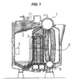
- FIG. 1 is a longitudinal sectional view showing a marine boiler to which a method and apparatus for cleaning a heat transfer tube of a marine boiler according to the present invention is applied.
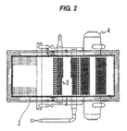
- FIG. 2 is a horizontal sectional view of the marine boiler.
- Drawing 3 is a mimetic diagram showing an embodiment of a washing device of a heat exchanger tube of a marine boiler concerning the present invention.
- FIG. 4 is a perspective view showing details of the nozzle unit.
- FIG. 5A is an image obtained by photographing the superheater tube before removing the scale attached to the outer surface of the superheater tube installed in the marine boiler.
- FIG. 5B shows the superheater tube surface condition after blast cleaning, with most of the scale removed but some scale remaining.
- FIG. 5A is an image obtained by photographing the superheater tube before removing the scale attached to the outer surface of the superheater tube installed in the marine boiler.
- FIG. 5B shows the superheater tube surface condition after blast cleaning, with most of the scale removed but some
- FIG. 5C is an image of the superheater tube after removing the scale attached to the outer surface of the superheater tube by blast cleaning.
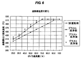
- FIG. 6 is a graph showing the operational effect of the marine boiler, and is a graph showing the steam temperature at the boiler superheater outlet with respect to the amount of boiler evaporation (boiler load).
- FIG. 1 is a longitudinal sectional view showing a marine boiler to which a method and apparatus for cleaning a heat transfer tube of a marine boiler according to the present invention is applied
- FIG. 2 is a horizontal sectional view of the marine boiler.
- the marine boiler is composed of a steam drum 1, a screen tube 2, a superheater tube 3, a water drum 4, an evaporation tube 6, and the like.
- Access holes 5 for entering and exiting workers are installed in each part of the boiler outer surface (only one access hole 5 is shown in FIG. 1).
- the marine boiler heat transfer tube cleaning method and apparatus of the present invention are applied to remove scales attached to the heat transfer tubes such as the screen tube 2, the superheater tube 3, and the evaporation tube 6.
- the screen tube 2, the superheater tube 3, and the evaporation tube 6 are collectively referred to as a heat transfer tube.
- FIG. 3 is a schematic view showing an embodiment of a heat transfer tube cleaning device for a marine boiler according to the present invention.
- the marine boiler heat transfer tube cleaning apparatus according to the present invention includes a blast cleaning apparatus that sprays blast material onto the heat transfer pipe to remove scale adhered to the heat transfer pipe.
- the blast cleaning apparatus 10 of the present invention includes a compressor 11, a blast apparatus 12, and a blast nozzle unit 13.
- the compressor 11 and the blast device 12 are connected by a pressure-resistant hose 14, and the blast device 12 and the blast nozzle unit 13 are connected by a blast hose 15.
- the blasting device 12 includes a pressurized tank 121 filled with a blast material, a recovery tank 122 for recovering a used blast material, and a filter 123.
- a gravity type valve (not shown) is installed between the pressurized tank 121 and the recovery tank 122.
- the lower end of the pressurized tank 121 is connected to the ejector portion 124.
- the recovery tank 122 and the filter 123 are connected by a hose 125.
- the compressed air pressurized by the compressor 11 is supplied to the upper part of the pressurized tank 121 through the pressure hose 14 and is ejected at the lower end of the pressurized tank 121. Supplied to the unit 124.
- the blast material in the pressurized tank 121 is pressurized by the compressed air and sucked to the negative pressure generated in the ejector portion 124.
- the blast material is pumped from the ejector portion 124 to the blast nozzle unit 13 via the blast hose 15.
- the blast material is sprayed from the blast nozzle unit 13 at a predetermined pressure to blast-clean the portion to be cleaned.
- the used blast material is sucked together with the scale removed from the heat transfer tube by the blast material suction duct 16 kept at a negative pressure, and is returned to the blast device 12.
- the blast material and scale are classified in the recovery tank 122 of the blast device 12, the blast material is recovered in the recovery tank 122 and reused, and the exhaust gas containing dust is filtered from the recovery tank 122 through the hose 125 to the filter 123. Sent to.
- the dust is captured by the filter 123 that constitutes the dust collecting unit, and the exhaust is released to the atmosphere.
- FIG. 4 is a perspective view showing details of the nozzle unit 13.
- the nozzle unit 13 includes a nozzle 131 that injects a blast material and an adapter pipe 132 that is connected to the nozzle 131.
- the nozzle 131 and the adapter tube 132 are connected by screwing. That is, a PT female screw is formed on the nozzle 131, a PT male screw is formed on the adapter tube 132, and the nozzle 131 and the adapter tube 132 are screwed together.
- the nozzle 131 is formed with an injection port 131n for injecting a blast material.
- FIG. 1 is formed with an injection port 131n for injecting a blast material.
- the diameter of the ejection port 131n is 7 mm
- the ejection angle of the ejection port 131n is 90 °, that is, the ejection port 131n is in a direction orthogonal to the longitudinal direction (axial direction) of the nozzle 131. It extends.
- the length of the adapter tube 132 is set to 300 mm to 500 mm including the nozzle 131.
- the adapter tube 132 uses aluminum piping. Since the adapter tube 132 is made of aluminum, the Vickers hardness of the adapter tube 132 can be maintained at 120 or less, so that even if the adapter tube 132 contacts the heat transfer tube or the boiler internal structure during blast cleaning, the adapter tube 132 is damaged. I will not let you.
- the outer diameters of the nozzle 131 and the adapter pipe 132 are set to be substantially the same, and are set to outer diameters that can be inserted into the piping group of the superheater pipe 3 and the evaporation pipe 6.
- the outer diameters of the nozzle 131 and the adapter tube 132 are set to 17 mm to 19 mm.
- the length of the adapter tube 132 is set to a length that reaches the end of the piping group of the superheater tube 3 and the evaporation tube 6, for example, 300 mm to 500 mm.
- the inner diameter of the blast material supply hole communicating with the injection port 131n formed in the nozzle 131 and the inner diameter of the blast material supply hole formed in the adapter tube 132 are the same.
- the inner diameter is set to be substantially the same as the inner diameter of the ejection port 131n or larger than the inner diameter of the ejection port 131n.
- Blasting materials generally used for blast cleaning include hard type, semi-hard type, and soft type.
- Hard type blasting materials include metal and ceramic types.
- Semi-hard type blasting materials include glass.
- metal types, and soft types include resin types and plant types.
- Table 1 shows the names of blast materials used (commercial product names), hardness, specific gravity, particle size, spray pressure during blast cleaning, and cleaning results.
- the width of the particle size value indicates the width of the minimum particle size and the maximum particle size and is selected by sieving.
- the heat transfer pipe of the marine boiler to be blast cleaned is a superheater pipe, and the superheater pipe made of alloy steel pipes “STBA22” and “fire STBA28” was blast washed.
- the exposure of the base material means that the oxide film formed on the surface of the heat transfer tube along with the scale is removed, and the material of the heat transfer tube can be seen.
- Test examples 1 to 5 will be described with reference to Table 1.
- Test Example 1 when a ceramic blast material is used, the grinding force is strong and the scale is removed from the heat transfer tube, but the base material of the heat transfer tube is also ground, so the blasting of the marine boiler It was inappropriate as a blasting material used for cleaning.
- Test Example 2 a metal blast material was used. In this case, although the grinding force is weaker than in the case of Test Example 1, a part of the base material of the heat transfer tube is exposed, and the blast material is a metal system. Since it is necessary to consider the possibility that the metal constituting the blast material comes into contact with the metal and causes corrosion due to the contact with different metals, it is inappropriate as a blast material.
- Test Example 3 a glass-based blast material was used.
- the grinding force of the glass-based blast material is similar to that in Test Example 2, but in order to prevent the base material from being exposed, it is necessary to maintain the injection pressure at a low pressure (0.3 MPa or less), and at one location. Time management for making the blast cleaning time short (one place within 5 seconds) must be performed, which is inappropriate as a blast material.
- Test Example 4 urea resin material POLYPLUS (registered trademark) # 30 to 40 and melamine resin material type III polyhard (POLYHARD) (registered trademark) # 30 to 40 are used as the resin blast material. Then, blast cleaning was performed at three injection pressures of 0.5 MPa, 0.6 MPa, and 0.65 MPa.
- the blast material of Test Example 4 was optimal as a blast material used for blast cleaning of a marine boiler. That is, only the scale of the heat transfer tube could be removed, and the oxide film of the heat transfer tube remained and the base material was not exposed.
- plant-based walnut # 30 was used as the blasting material, and blast cleaning was performed when the spray pressure was 0.4 MPa and 0.65 MPa.
- Plant-based blasting materials are the most suitable blasting materials for blast cleaning of marine boilers.
- the walnut, a plant-based blasting material used here, is an abrasive that has been crushed to a desired particle size using walnut shells, which are nuts, as raw materials. Abrasive material processed in the same manner using the seeds of
- FIG. 5A to 5C are images obtained by photographing the superheater tube before and after removing the scale attached to the outer surface of the superheater tube installed in the marine boiler.
- the superheater pipe with the scale attached is used in an actual marine boiler and the scale is attached, and the superheater pipe is made of STBA22. Blast cleaning was performed using a plant blast material as the blast material and an injection pressure of 0.6 MPa.
- FIG. 5A shows the surface state of the superheater tube before blast cleaning, and the scale is thickly attached to the surface.
- FIG. 5B shows the surface condition of the superheater tube after blast cleaning, with most of the scale removed but some scale remaining.
- FIG. 5C shows the surface state of the superheater tube after the surface of the superheater tube after cleaning shown in FIG. 5B is further subjected to blast cleaning as a finishing treatment. That is, in FIG. 5C, almost all the scale is removed, but the oxide film remains without being removed.
- the above-described blast cleaning as the finishing treatment is to perform blast cleaning again after the blast cleaning, by moistening the blast cleaning surface. Wetting of the blast cleaning surface is performed by spraying water with a spray spray after blast cleaning. It is considered that the sulfur oxide, which is one of the main components of the scale remaining on the blast cleaning surface, reacts with water to become a water-soluble substance, so that the remaining portion of the scale becomes brittle and easy to remove by washing.
- FIG. 6 is a graph showing the operational effect of the marine boiler, and is a graph showing the steam temperature at the boiler superheater outlet with respect to the amount of boiler evaporation (boiler load).
- dots indicated by black diamonds indicate data at the time of trial operation of the marine boiler. That is, the operation effect when the boiler is operated in a state where the scale is not attached to the superheater pipe of the marine boiler is shown.
- the black rhombus after the boiler evaporation amount (boiler load) reaches 70%, the steam temperature at the outlet of the superheater is maintained at 515 ° C. (set temperature).
- set temperature 515 ° C.
- points indicated by black squares indicate the operational effect after operating the marine boiler for a predetermined period.
- the amount of boiler evaporation is 70%
- the steam temperature at the outlet of the superheater is less than 480 ° C.
- the set temperature has not reached 515 ° C.
- points indicated by ⁇ and ⁇ indicate the operation effect of the boiler after blast cleaning according to the present invention is applied to different ship boilers.
- the data indicated by ⁇ is obtained by blast cleaning using walnuts as a blast material and an injection pressure of 0.5 MPa
- the data indicated by ⁇ indicates walnuts as a blast material. It was obtained by blast cleaning that was used and the injection pressure was 0.5 MPa.
- the present invention can be used in a cleaning method and apparatus for removing scales attached to the outer surfaces of an evaporator tube, a superheater tube, and a screen tube installed in a boiler mounted on a ship.
Landscapes
- Engineering & Computer Science (AREA)
- Chemical & Material Sciences (AREA)
- Combustion & Propulsion (AREA)
- Mechanical Engineering (AREA)
- General Engineering & Computer Science (AREA)
- Cleaning In General (AREA)
Abstract
本発明は、舶用ボイラの伝熱管の洗浄方法及び装置に係り、特に船舶に搭載されているボイラ内に設置された蒸発管、過熱器管及びスクリーン管の外面に付着しているスケールを除去するための洗浄方法及び装置に関するものである。舶用ボイラの伝熱管の洗浄方法及び装置は、舶用ボイラの伝熱管にブラスト材を噴射して伝熱管に付着したスケールを除去する洗浄方法であって、前記ブラスト材に植物系ブラスト材又は樹脂系ブラスト材を用いることにより、前記伝熱管に付着したスケールを除去し、かつ前記伝熱管の表面に形成された酸化皮膜は除去せずに残すようにした。
Description
本発明は、舶用ボイラの伝熱管の洗浄方法及び装置に係り、特に船舶に搭載されているボイラ内に設置された蒸発管、過熱器管及びスクリーン管の外面に付着しているスケールを除去するための洗浄方法及び装置に関するものである。
舶用ボイラの内部には、水や水蒸気を内部に循環させた伝熱管が多数設置されている。舶用ボイラの伝熱管には、蒸発管、過熱器管およびスクリーン管が含まれており、燃焼ガスが伝熱管に接触する際に燃焼ガスと伝熱管との間で熱交換が行われ、燃焼ガスから熱回収を行う。しかしながら、燃焼ガス中の様々な成分が伝熱管の表面に凝集し、伝熱管の表面にスケールと称される付着物が堆積する。
舶用ボイラの燃料には、一般的にC重油が用いられているが、C重油には硫黄分が多く含有されているため、C重油が燃焼すると硫黄分と酸素が結合して亜硫酸になり、燃焼残渣として伝熱管や炉底耐火材に付着する。そのため、伝熱管に付着したスケール中には、亜硫酸が含まれる。
従来、舶用ボイラの蒸発管、過熱器管およびスクリーン管に付着したスケールを除去するために、ボイラ内に作業員が立ち入って、水洗を行っている。
ボイラの蒸発管、過熱器管、スクリーン管及び炉底耐火材に亜硫酸が付着している状態で水洗を実施すると、H2O+SO3→H2SO4の化学反応により硫酸が生成されて酸性廃液となる。この酸性側になった硫酸含有水は蒸発管、過熱器管及びスクリーン管に対して低温腐食と呼ばれる硫酸腐食が起こる。
ボイラの蒸発管、過熱器管、スクリーン管及び炉底耐火材に亜硫酸が付着している状態で水洗を実施すると、H2O+SO3→H2SO4の化学反応により硫酸が生成されて酸性廃液となる。この酸性側になった硫酸含有水は蒸発管、過熱器管及びスクリーン管に対して低温腐食と呼ばれる硫酸腐食が起こる。
硫酸腐食を起こした蒸発管、過熱器管及びスクリーン管は、管外面が侵食されて管肉厚が薄くなり、ボイラの運転を続けていると管内圧に耐えられなくなり管の噴破が起こる。管が噴破すると、ボイラを停止し、当該噴破部の補修を実施する必要があり、船舶の運航にも支障を来すことになる。
また、水洗を行う際には、事前に耐火材の養生を実施し耐火材に水分が浸透しないように対策をとるが、耐火材養生が不十分であった場合、耐火材に酸性廃液が浸透し、耐火材は劣化して耐火材の機能がなくなり、ボイラの外面を覆っているスキンケーシングと呼ばれる鋼板も低温腐食と呼ばれる硫酸腐食により破孔に拍車がかかることになる。
ボイラの外面を覆っているスキンケーシングと呼ばれる鋼板が破孔すると、燃焼ガスが機関室内に漏れることになり、人命に関わる大変危険な状態となる。また、炉底部に溜まった洗浄廃水の水質は、スケール中に含まれている亜硫酸により酸性側になり、別途、排水処理作業を実施する必要がある。
ボイラの外面を覆っているスキンケーシングと呼ばれる鋼板が破孔すると、燃焼ガスが機関室内に漏れることになり、人命に関わる大変危険な状態となる。また、炉底部に溜まった洗浄廃水の水質は、スケール中に含まれている亜硫酸により酸性側になり、別途、排水処理作業を実施する必要がある。
上述したように、ボイラの蒸発管、過熱器管およびスクリーン管を水洗してスケールを除去する方法では、硫酸含有水が生成されるため、蒸発管、過熱器管およびスクリーン管の硫酸腐食が起こるという問題点や耐火材が劣化したり酸性側廃液の処理をする必要がある等の種々の問題点がある。
そのため、本発明者らは、舶用ボイラにおいて、洗浄水を用いることなく蒸発管、過熱器管およびスクリーン管からスケールを除去することができる方法について鋭意研究を行ったものである。
そのため、本発明者らは、舶用ボイラにおいて、洗浄水を用いることなく蒸発管、過熱器管およびスクリーン管からスケールを除去することができる方法について鋭意研究を行ったものである。
そこで、本発明者らは、ブラスト材を噴射させてその衝撃力で付着物を除去するブラスト洗浄を舶用ボイラの蒸発管、過熱器管およびスクリーン管の洗浄に適用することを検討したものである。
まず、本発明者らは、蒸発管、過熱器管およびスクリーン管の表面状態を分析するとともに鋼管に付着したスケールを分析した。その結果、蒸発管、過熱器管およびスクリーン管の母材の表面には、薄い酸化皮膜が形成されており、この酸化皮膜の表面にスケールが付着して堆積していることを見出した。
また、スケールの主成分は下記の3種類であった。
・酸化バナジウム(V205):40~50%
・ヘマタイト(Fe2O3):20~25%
・硫黄酸化物:約10%
・その他:Ni,Na,Si,Al,Cr等の酸化物で、いずれも数%以下
まず、本発明者らは、蒸発管、過熱器管およびスクリーン管の表面状態を分析するとともに鋼管に付着したスケールを分析した。その結果、蒸発管、過熱器管およびスクリーン管の母材の表面には、薄い酸化皮膜が形成されており、この酸化皮膜の表面にスケールが付着して堆積していることを見出した。
また、スケールの主成分は下記の3種類であった。
・酸化バナジウム(V205):40~50%
・ヘマタイト(Fe2O3):20~25%
・硫黄酸化物:約10%
・その他:Ni,Na,Si,Al,Cr等の酸化物で、いずれも数%以下
舶用ボイラの蒸発管、過熱器管およびスクリーン管には、ボイラ・熱交換器用合金鋼管(STBA22、STBA24、火STBA28、STBA35等)が用いられているが、これらの鋼管の表面には、ボイラ運転時に空気中の酸素と反応して薄い酸化皮膜が形成されている。この酸化皮膜は四酸化三鉄(Fe3O4)を主体とする緻密な構造の酸化鉄皮膜であり、耐摩耗性や耐食性に富んでいるものである。
そこで、本発明者らは、ブラスト洗浄によって蒸発管、過熱器管およびスクリーン管からスケールは除去するが、耐摩耗性や耐食性に富んだ酸化皮膜は除去することなく残すことが鋼管の母材を保護する観点から好ましいという知見を得たものである。
次に、本発明者らは、配管等をブラスト洗浄する際に用いられているセラミック系ブラスト材、ガラスビーズで舶用ボイラの蒸発管、過熱器管およびスクリーン管のブラスト洗浄試験を実施した。そして、ブラスト洗浄後に蒸発管、過熱器管およびスクリーン管からスケールが除去されているか否かを検査し、かつ鋼管の表面の分析を行った。その結果、蒸発管、過熱器管およびスクリーン管からスケールは除去されているが、鋼管の母材まで研削されてしまっていることが判明した。
本発明は、上述の事情に鑑みなされたもので、舶用ボイラの蒸発管、過熱器管およびスクリーン管等の伝熱管の酸化皮膜および母材に影響を与えることなく、ブラスト洗浄によってスケールを除去することができる舶用ボイラの伝熱管の洗浄方法及び装置を提供することを目的とする。
本発明者らは、セラミック系ブラスト材、ガラスビーズで舶用ボイラの伝熱管のブラスト洗浄を実施する場合、ブラスト材を噴射する圧力を低圧にしてブラスト時に伝熱管に加わる衝撃力を弱めることにより、伝熱管表面の酸化皮膜を残そうとした。しかしながら、0.2MPa程度の低圧で約5秒間同一箇所をブラスト洗浄をした場合でも母材が露出してしまうことが判明した。
そこで、本発明者らは、各種ブラスト材を用いて伝熱管のブラスト洗浄を繰り返し行った結果、植物系ブラスト材または樹脂系ブラスト材を用いることで伝熱管から酸化皮膜を取り除くことなくスケールのみを除去することができるという知見を得たものである。
そこで、本発明者らは、各種ブラスト材を用いて伝熱管のブラスト洗浄を繰り返し行った結果、植物系ブラスト材または樹脂系ブラスト材を用いることで伝熱管から酸化皮膜を取り除くことなくスケールのみを除去することができるという知見を得たものである。
本発明の第一の態様は、上記知見に基づいてなされたもので、舶用ボイラの伝熱管にブラスト材を噴射して伝熱管に付着したスケールを除去する洗浄方法であって、前記ブラスト材に植物系ブラスト材又は樹脂系ブラスト材を用いることにより、前記伝熱管に付着したスケールを除去し、かつ前記伝熱管の表面に形成された酸化皮膜は除去せずに残すようにしたことを特徴とする。
本発明によれば、植物系ブラスト材または樹脂系ブラスト材を用いてブラスト洗浄することにより、伝熱管から酸化皮膜を取り除くことなくスケールのみを除去することができる。伝熱管に形成された酸化皮膜は、四酸化三鉄(Fe3O4)を主体とする緻密な構造の酸化鉄皮膜であり、耐摩耗性や耐食性に富んでいるため、酸化皮膜により伝熱管の母材を保護することができる。
植物系ブラスト材または樹脂系ブラスト材を用いてブラスト洗浄することにより、0.6MPaの噴射圧力で30秒以上といった高圧・長時間の洗浄であっても伝熱管から酸化皮膜を取り除くことなくスケールのみを除去することができる。
本発明によれば、植物系ブラスト材または樹脂系ブラスト材を用いてブラスト洗浄することにより、伝熱管から酸化皮膜を取り除くことなくスケールのみを除去することができる。伝熱管に形成された酸化皮膜は、四酸化三鉄(Fe3O4)を主体とする緻密な構造の酸化鉄皮膜であり、耐摩耗性や耐食性に富んでいるため、酸化皮膜により伝熱管の母材を保護することができる。
植物系ブラスト材または樹脂系ブラスト材を用いてブラスト洗浄することにより、0.6MPaの噴射圧力で30秒以上といった高圧・長時間の洗浄であっても伝熱管から酸化皮膜を取り除くことなくスケールのみを除去することができる。
本発明の好ましい態様は、前記ブラスト材の噴射は、0.4~0.65MPaで行うことを特徴とする。
本発明の好ましい態様は、植物系ブラスト材は、クルミ殻または杏の種または桃の種を所定の粒径に砕いた粒状物からなることを特徴とする。
本発明の好ましい態様は、前記植物系ブラスト材の所定の粒径は、500~700μmであることを特徴とする
本発明の好ましい態様は、植物系ブラスト材は、クルミ殻または杏の種または桃の種を所定の粒径に砕いた粒状物からなることを特徴とする。
本発明の好ましい態様は、前記植物系ブラスト材の所定の粒径は、500~700μmであることを特徴とする
本発明の好ましい態様は、前記樹脂系ブラスト材は、ナイロンまたはポリカーボネートまたはユリア樹脂またはメラミン樹脂を所定の粒径に成形した粒状物からなることを特徴とする。
本発明の好ましい態様は、前記樹脂系ブラスト材の所定の粒径は、420~595μmであることを特徴とする。
本発明の好ましい態様は、前記樹脂系ブラスト材の所定の粒径は、420~595μmであることを特徴とする。
本発明の好ましい態様は、前記伝熱管にブラスト材を噴射して伝熱管に付着したスケールを除去した後に、前記伝熱管の被洗浄面を湿潤化させ、その後、再度、前記伝熱管にブラスト材を噴射して伝熱管に付着したスケールを除去するようにしたことを特徴とする。
本発明によれば、ブラスト洗浄後に仕上げとして洗浄面を湿潤化させ、スケール中の水溶性成分を溶解させた後再度ブラスト洗浄を実施することによって、最初のブラスト洗浄で除去しにくかったスケールが容易に除去できる。
本発明の好ましい態様は、前記被洗浄面の湿潤化は、水を噴霧することにより行うことを特徴とする。
本発明によれば、ブラスト洗浄後に仕上げとして洗浄面を湿潤化させ、スケール中の水溶性成分を溶解させた後再度ブラスト洗浄を実施することによって、最初のブラスト洗浄で除去しにくかったスケールが容易に除去できる。
本発明の好ましい態様は、前記被洗浄面の湿潤化は、水を噴霧することにより行うことを特徴とする。
本発明の好ましい態様は、前記伝熱管が千鳥格子状又は直列格子状に密集している箇所に前記ブラスト材を噴きつけるために、ノズルユニットを用いることを特徴とする。
本発明の第二の態様は、舶用ボイラの伝熱管にブラスト材を噴射して伝熱管に付着したスケールを除去する洗浄装置であって、ブラスト材を充填したタンクと、圧縮空気源から供給される圧縮空気により前記タンク内のブラスト材を加圧するブラスト材調整部と、前記ブラスト材調整部に接続され、前記ブラスト材を圧縮空気とともに吹き出すノズルユニットとを備え、前記ブラスト材に植物系ブラスト材又は樹脂系ブラスト材を用いることにより、前記伝熱管に付着したスケールを除去し、かつ前記伝熱管の表面に形成された酸化皮膜は除去せずに残すようにしたことを特徴とする。
本発明によれば、圧縮空気はタンクの上部に供給されるとともにタンクの下端のブラスト材調整部に供給され、タンク内のブラスト材は、圧縮空気により加圧されブラスト材調整部へ落下し、ブラスト材調整部に直接接続されている圧縮空気と混合されノズルユニットに圧送される。そして、ブラスト材は、ノズルユニットから所定の圧力で噴射され伝熱管をブラスト洗浄する。ブラスト材に植物系ブラスト材または樹脂系ブラスト材を用いてブラスト洗浄することにより、伝熱管から酸化皮膜を取り除くことなくスケールのみを除去することができる。伝熱管に形成された酸化皮膜は、四酸化三鉄(Fe3O4)を主体とする緻密な構造の酸化鉄皮膜であり、耐摩耗性や耐食性に富んでいるため、酸化皮膜により伝熱管の母材を保護することができる。
本発明によれば、圧縮空気はタンクの上部に供給されるとともにタンクの下端のブラスト材調整部に供給され、タンク内のブラスト材は、圧縮空気により加圧されブラスト材調整部へ落下し、ブラスト材調整部に直接接続されている圧縮空気と混合されノズルユニットに圧送される。そして、ブラスト材は、ノズルユニットから所定の圧力で噴射され伝熱管をブラスト洗浄する。ブラスト材に植物系ブラスト材または樹脂系ブラスト材を用いてブラスト洗浄することにより、伝熱管から酸化皮膜を取り除くことなくスケールのみを除去することができる。伝熱管に形成された酸化皮膜は、四酸化三鉄(Fe3O4)を主体とする緻密な構造の酸化鉄皮膜であり、耐摩耗性や耐食性に富んでいるため、酸化皮膜により伝熱管の母材を保護することができる。
本発明の好ましい態様は、さらに前記伝熱管の被洗浄面に水を噴霧する霧吹きを備えることを特徴とする。
本発明によれば、ブラスト洗浄後に仕上げとして洗浄面を霧吹きにより湿潤化させ、再度ブラスト洗浄を実施することによって、最初のブラスト洗浄で除去しにくかったスケールが容易に除去できる。
本発明によれば、ブラスト洗浄後に仕上げとして洗浄面を霧吹きにより湿潤化させ、再度ブラスト洗浄を実施することによって、最初のブラスト洗浄で除去しにくかったスケールが容易に除去できる。
本発明の好ましい態様は、さらに前記伝熱管に噴射された使用済みブラスト材を吸引するブラスト材吸引ダクトと、該ブラスト材吸引ダクトにより吸引されたブラスト材を回収する回収用タンクと、該回収用タンクに接続されブラスト材を吸引する排気から集塵する集塵部とを備えることを特徴とする。
本発明によれば、使用済のブラスト材は、負圧に保たれているブラスト材吸引ダクトにより、伝熱管から除去されたスケールとともに吸引され、回収用タンクに返送される。ブラスト材およびスケールは、回収用タンク内で分級され、ブラスト材は回収用タンクに回収され再利用され、粉塵を含む排気は回収用タンクから集塵部に送られる。粉塵は、集塵部に捕捉され、排気は大気に放出される。
本発明によれば、使用済のブラスト材は、負圧に保たれているブラスト材吸引ダクトにより、伝熱管から除去されたスケールとともに吸引され、回収用タンクに返送される。ブラスト材およびスケールは、回収用タンク内で分級され、ブラスト材は回収用タンクに回収され再利用され、粉塵を含む排気は回収用タンクから集塵部に送られる。粉塵は、集塵部に捕捉され、排気は大気に放出される。
本発明の好ましい態様は、前記ノズルユニットは、前記伝熱管に接触する可能性がある部分に、軟質の材料を用いることを特徴とする。
前記軟質の材料には、例えば、アルミニウム、アルミニウム合金などがある。
前記軟質の材料には、例えば、アルミニウム、アルミニウム合金などがある。
本発明の好ましい態様は、前記ノズルユニットは、前記ブラスト材を噴射するためのノズルと、該ノズルを保持するアダプタとからなることを特徴とする。
本発明によれば、アダプタの長さをボイラの伝熱管群のサイズに応じて選定することにより、ノズルが伝熱管群の末端まで届くようになる。
本発明によれば、アダプタの長さをボイラの伝熱管群のサイズに応じて選定することにより、ノズルが伝熱管群の末端まで届くようになる。
本発明の好ましい態様は、前記アダプタはアルミニウム製であることを特徴とする。
本発明によれば、アダプタに軟質材料であるアルミニウムを用いているため、ブラスト洗浄中にアダプタが伝熱管やボイラ内構造物に接触しても、これらを損傷させることがない。
本発明によれば、アダプタに軟質材料であるアルミニウムを用いているため、ブラスト洗浄中にアダプタが伝熱管やボイラ内構造物に接触しても、これらを損傷させることがない。
本発明は、以下に列挙する効果を奏する。
(1)舶用ボイラの蒸発管、過熱器管およびスクリーン管に付着したスケールをブラスト洗浄によって除去することができるため、洗浄水を用いる必要がなく、硫酸含有水が生成されることがなく、蒸発管、過熱器管およびスクリーン管の硫酸腐食が起こるという問題点や耐火材が劣化したり酸性側廃液の処理をする必要がある等の問題点を解消することができる。
(2)植物系ブラスト材または樹脂系ブラスト材を用いてブラスト洗浄することにより、伝熱管から酸化皮膜を取り除くことなくスケールのみを除去することができる。伝熱管に形成された酸化皮膜は、四酸化三鉄(Fe3O4)を主体とする緻密な構造の酸化鉄皮膜であり、耐摩耗性や耐食性に富んでいるため、酸化皮膜により伝熱管の母材を保護することができる。
(3)舶用ボイラの蒸発管、過熱器管およびスクリーン管をブラスト洗浄するだけで済むため、誰もが使いやすい操作で安全に作業でき、ボイラ管理上においても安全な作業が提供できる。
(4)植物系ブラスト材を用いることにより、ブラスト材が洗浄後に炉内に残留してもボイラを運転することにより焼却可能であり、また植物材料を使用するため環境に負荷を与えないでブラスト洗浄が可能である。
(5)ブラスト洗浄後に仕上げとして洗浄面を湿潤化させ、再度ブラスト洗浄を実施することによって、最初のブラスト洗浄で除去しにくかったスケールが容易に除去できる。
(1)舶用ボイラの蒸発管、過熱器管およびスクリーン管に付着したスケールをブラスト洗浄によって除去することができるため、洗浄水を用いる必要がなく、硫酸含有水が生成されることがなく、蒸発管、過熱器管およびスクリーン管の硫酸腐食が起こるという問題点や耐火材が劣化したり酸性側廃液の処理をする必要がある等の問題点を解消することができる。
(2)植物系ブラスト材または樹脂系ブラスト材を用いてブラスト洗浄することにより、伝熱管から酸化皮膜を取り除くことなくスケールのみを除去することができる。伝熱管に形成された酸化皮膜は、四酸化三鉄(Fe3O4)を主体とする緻密な構造の酸化鉄皮膜であり、耐摩耗性や耐食性に富んでいるため、酸化皮膜により伝熱管の母材を保護することができる。
(3)舶用ボイラの蒸発管、過熱器管およびスクリーン管をブラスト洗浄するだけで済むため、誰もが使いやすい操作で安全に作業でき、ボイラ管理上においても安全な作業が提供できる。
(4)植物系ブラスト材を用いることにより、ブラスト材が洗浄後に炉内に残留してもボイラを運転することにより焼却可能であり、また植物材料を使用するため環境に負荷を与えないでブラスト洗浄が可能である。
(5)ブラスト洗浄後に仕上げとして洗浄面を湿潤化させ、再度ブラスト洗浄を実施することによって、最初のブラスト洗浄で除去しにくかったスケールが容易に除去できる。
図1は、本発明の舶用ボイラの伝熱管の洗浄方法及び装置が適用される舶用ボイラを示す縦断面図である。
図2は舶用ボイラの水平断面図である。
図3は、本発明に係る舶用ボイラの伝熱管の洗浄装置の実施形態を示す模式図である。
図4は、ノズルユニットの詳細を示す斜視図である。
図5Aは、舶用ボイラ内に設置された過熱器管の外面に付着しているスケールを除去する前の過熱器管を撮影した画像である。
図5Bは、ブラスト洗浄後の過熱器管の表面状態を示しており、ほとんどのスケールは除去されているが、若干のスケールが残っている画像である。
図5Cは、ブラスト洗浄により過熱器管の外面に付着しているスケールを除去した後の過熱器管を撮影した画像である。
図6は、舶用ボイラの運転効果を示すグラフであり、ボイラの蒸発量(ボイラ負荷)に対するボイラの過熱器出口の蒸気温度を示すグラフである。
図2は舶用ボイラの水平断面図である。
図3は、本発明に係る舶用ボイラの伝熱管の洗浄装置の実施形態を示す模式図である。
図4は、ノズルユニットの詳細を示す斜視図である。
図5Aは、舶用ボイラ内に設置された過熱器管の外面に付着しているスケールを除去する前の過熱器管を撮影した画像である。
図5Bは、ブラスト洗浄後の過熱器管の表面状態を示しており、ほとんどのスケールは除去されているが、若干のスケールが残っている画像である。
図5Cは、ブラスト洗浄により過熱器管の外面に付着しているスケールを除去した後の過熱器管を撮影した画像である。
図6は、舶用ボイラの運転効果を示すグラフであり、ボイラの蒸発量(ボイラ負荷)に対するボイラの過熱器出口の蒸気温度を示すグラフである。
以下、本発明に係る舶用ボイラの伝熱管の洗浄方法及び装置の実施形態について図1乃至図6を参照して説明する。なお、図1乃至図6において、同一または相当する構成要素には、同一の符号を付して重複した説明を省略する。
図1は、本発明の舶用ボイラの伝熱管の洗浄方法及び装置が適用される舶用ボイラを示す縦断面図であり、図2は舶用ボイラの水平断面図である。図1および図2に示すように、舶用ボイラは、蒸気ドラム1、スクリーン管2、過熱器管3、水ドラム4、蒸発管6等から構成されている。ボイラ外面の各部には、作業員出入用のアクセスホール5が設置されている(図1では1つのアクセスホール5のみを示している)。
図1は、本発明の舶用ボイラの伝熱管の洗浄方法及び装置が適用される舶用ボイラを示す縦断面図であり、図2は舶用ボイラの水平断面図である。図1および図2に示すように、舶用ボイラは、蒸気ドラム1、スクリーン管2、過熱器管3、水ドラム4、蒸発管6等から構成されている。ボイラ外面の各部には、作業員出入用のアクセスホール5が設置されている(図1では1つのアクセスホール5のみを示している)。
本発明の舶用ボイラの伝熱管の洗浄方法及び装置は、スクリーン管2、過熱器管3および蒸発管6等の伝熱管に付着したスケールを取り除くために適用される。以下の説明においては、スクリーン管2、過熱器管3および蒸発管6を総称する場合に伝熱管という。
図3は、本発明に係る舶用ボイラの伝熱管の洗浄装置の実施形態を示す模式図である。本発明に係る舶用ボイラの伝熱管の洗浄装置は、ブラスト材を伝熱管に噴きつけて伝熱管に付着したスケールを除去するブラスト洗浄装置から構成されている。図3に示すように、本発明のブラスト洗浄装置10は、コンプレッサ11、ブラスト装置12、ブラストノズルユニット13とを備えている。コンプレッサ11とブラスト装置12とは耐圧ホース14により接続されており、ブラスト装置12とブラストノズルユニット13とはブラストホース15により接続されている。ブラスト装置12は、ブラスト材が充填された加圧タンク121と、使用済のブラスト材を回収する回収用タンク122と、フィルタ123とを備えている。加圧タンク121と回収用タンク122との間には、重力式のバルブ(図示せず)が設置されている。加圧タンク121の下端はエジェクタ部124に接続されている。回収用タンク122とフィルタ123とはホース125によって接続されている。
図3に示すように構成されたブラスト洗浄装置10において、コンプレッサ11で加圧された圧縮空気は耐圧ホース14を介して加圧タンク121の上部に供給されるとともに加圧タンク121の下端のエジェクタ部124に供給される。その結果、加圧タンク121内のブラスト材は、圧縮空気により加圧されるとともにエジェクタ部124に生ずる負圧に吸引される。その結果、ブラスト材は、エジェクタ部124からブラストホース15を介してブラストノズルユニット13に圧送される。そして、ブラスト材は、ブラストノズルユニット13から所定の圧力で噴射され洗浄対象部をブラスト洗浄する。使用済のブラスト材は、負圧に保たれているブラスト材吸引ダクト16により、伝熱管から除去されたスケールとともに吸引され、ブラスト装置12に返送される。ブラスト材およびスケールは、ブラスト装置12の回収用タンク122内で分級され、ブラスト材は回収用タンク122に回収され再利用され、粉塵を含む排気は回収用タンク122からホース125を介してフィルタ123に送られる。粉塵は、集塵部を構成するフィルタ123に捕捉され、排気は大気に放出される。
図4は、ノズルユニット13の詳細を示す斜視図である。図4に示すように、ノズルユニット13は、ブラスト材を噴射するノズル131と、ノズル131に接続されるアダプタ管132とから構成されている。ノズル131とアダプタ管132とはねじ込み接続されている。すなわち、ノズル131にはPT雌ねじが形成されており、アダプタ管132にはPT雄ねじが形成されており、ノズル131とアダプタ管132とはねじ込み接続されている。ノズル131には、ブラスト材を噴射する噴射口131nが形成されている。図4に示す実施形態では、噴射口131nの口径は7mmであり、噴射口131nの噴射角度は90°、すなわち、噴射口131nはノズル131の長手方向(軸方向)に対して直交する方向に延びている。なお、二点鎖線で示すように、噴射口131nはノズル131の長手方向(軸方向)に開口するように形成してもよい。
また、アダプタ管132の長さはノズル131も含め300mm~500mmに設定されている。アダプタ管132はアルミニウム製の配管を用いたものである。アダプタ管132がアルミニウム製であるため、アダプタ管132のビッカース硬度を120以下に保つことができるので、ブラスト洗浄中にアダプタ管132が伝熱管やボイラ内構造物に接触しても、これらを損傷させることがない。
ノズル131およびアダプタ管132の外径は、略同一に設定されており、過熱器管3および蒸発管6の配管群の中に挿入できる外径に設定されている。本実施形態においては、ノズル131およびアダプタ管132の外径は17mm~19mmに設定されている。また、アダプタ管132の長さは、過熱器管3および蒸発管6の配管群の末端まで届くような長さ、例えば、300mm~500mmに設定されている。また、ノズル131内に形成された噴射口131nに連通するブラスト材供給孔の内径と、アダプタ管132内に形成されたブラスト材供給孔の内径とは、同一であり、これらブラスト材供給孔の内径は、噴射口131nの内径と略同一か又は噴射口131nの内径より大きく設定されている。
次に、本発明において使用されるブラスト材について説明する。
一般的にブラスト洗浄に使用されるブラスト材としては、ハードタイプ、セミハードタイプ、ソフトタイプがあり、ハードタイプのブラスト材としては金属系、セラミック系等があり、セミハードタイプのブラスト材としてはガラス系、金属系があり、ソフトタイプとしては樹脂系、植物系等がある。
本発明において洗浄の対象となる舶用ボイラの伝熱管を、セラミック系、金属系、ガラス系、樹脂系、植物系の各種ブラスト材を用いてブラスト洗浄を行った。使用したブラスト材の名称(市販品名)、硬度、比重、粒径、ブラスト洗浄時の噴射圧力およびその洗浄結果を表1に示す。表1において、粒径値の幅は最低粒径と最高粒径の幅を示し、篩い分けにて選別している。ブラスト洗浄の対象となる舶用ボイラの伝熱管は過熱器管であり、材質は合金鋼管の“STBA22”及び“火STBA28”からなる過熱器管をブラスト洗浄した。ここで、母材が露出するとは、スケールとともに伝熱管の表面に形成された酸化皮膜が除去されて伝熱管の材質が見えることをいう。
一般的にブラスト洗浄に使用されるブラスト材としては、ハードタイプ、セミハードタイプ、ソフトタイプがあり、ハードタイプのブラスト材としては金属系、セラミック系等があり、セミハードタイプのブラスト材としてはガラス系、金属系があり、ソフトタイプとしては樹脂系、植物系等がある。
本発明において洗浄の対象となる舶用ボイラの伝熱管を、セラミック系、金属系、ガラス系、樹脂系、植物系の各種ブラスト材を用いてブラスト洗浄を行った。使用したブラスト材の名称(市販品名)、硬度、比重、粒径、ブラスト洗浄時の噴射圧力およびその洗浄結果を表1に示す。表1において、粒径値の幅は最低粒径と最高粒径の幅を示し、篩い分けにて選別している。ブラスト洗浄の対象となる舶用ボイラの伝熱管は過熱器管であり、材質は合金鋼管の“STBA22”及び“火STBA28”からなる過熱器管をブラスト洗浄した。ここで、母材が露出するとは、スケールとともに伝熱管の表面に形成された酸化皮膜が除去されて伝熱管の材質が見えることをいう。
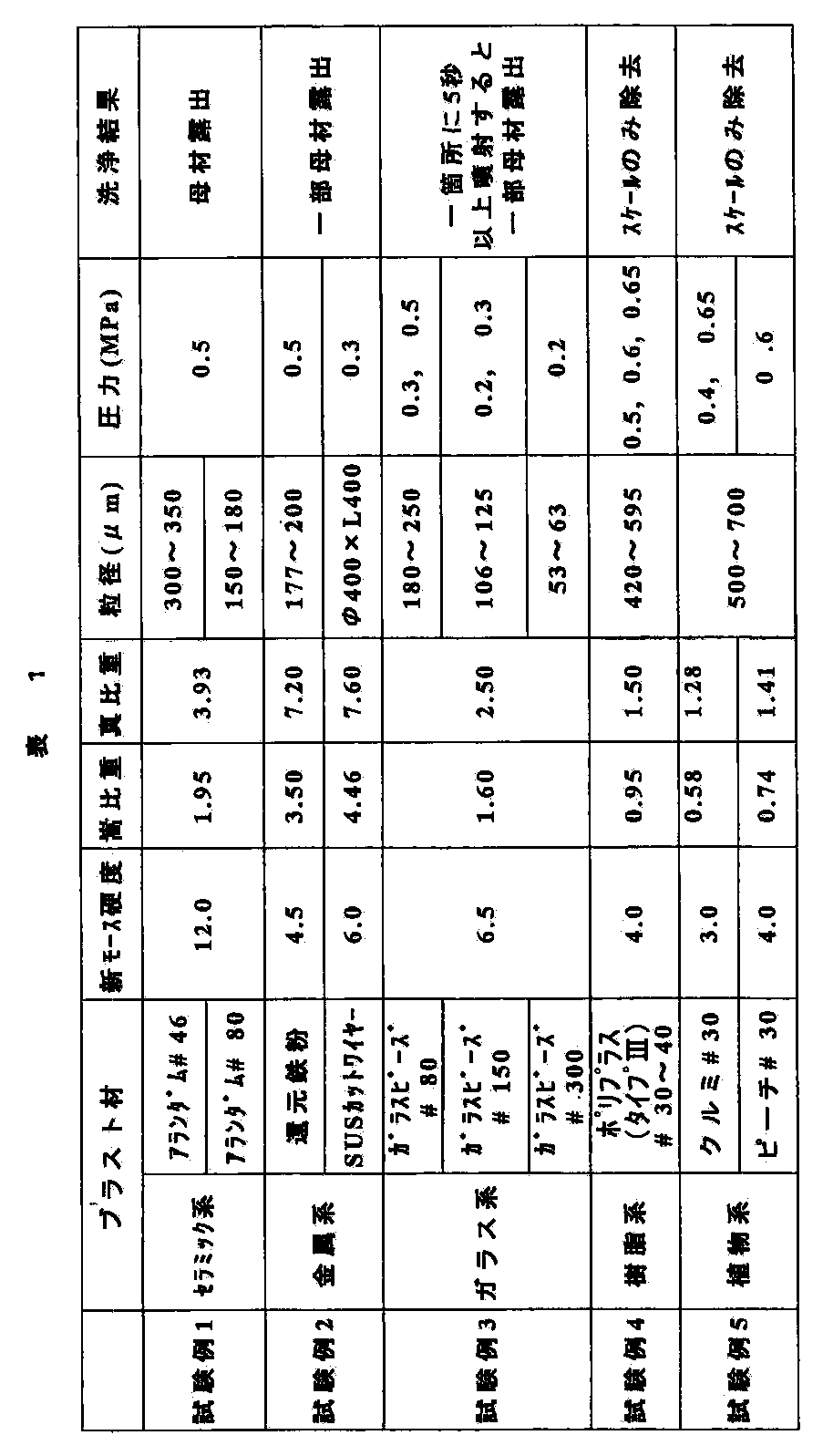
表1を参照して、試験例1~5について説明する。
試験例1に示すように、セラミック系ブラスト材を使用した場合には、研削力が強く、伝熱管からスケールが除去されるが、伝熱管の母材まで研削されてしまうため、舶用ボイラのブラスト洗浄に使用するブラスト材としては不適切であった。
試験例2においては、金属系のブラスト材を使用した。この場合、研削力は試験例1の場合よりは弱いが伝熱管の母材の一部が露出してしまうことと、ブラスト材が金属系であるため、ブラスト洗浄により伝熱管を構成する金属とブラスト材を構成する金属とが接触し、異種金属接触に起因する腐食を引き起こす可能性を考慮しなければならないため、ブラスト材としては不適切であった。
試験例3においては、ガラス系のブラスト材を使用した。ガラス系ブラスト材の研削力は試験例2の場合と同程度であるが、母材の露出を防ぐには、噴射圧力を低圧力(0.3MPa以下)に保つ必要があり、しかも一箇所のブラスト洗浄時間を短時間(一箇所を5秒以内)とする時間管理を行わなければならず、ブラスト材としては不適切であった。
試験例1に示すように、セラミック系ブラスト材を使用した場合には、研削力が強く、伝熱管からスケールが除去されるが、伝熱管の母材まで研削されてしまうため、舶用ボイラのブラスト洗浄に使用するブラスト材としては不適切であった。
試験例2においては、金属系のブラスト材を使用した。この場合、研削力は試験例1の場合よりは弱いが伝熱管の母材の一部が露出してしまうことと、ブラスト材が金属系であるため、ブラスト洗浄により伝熱管を構成する金属とブラスト材を構成する金属とが接触し、異種金属接触に起因する腐食を引き起こす可能性を考慮しなければならないため、ブラスト材としては不適切であった。
試験例3においては、ガラス系のブラスト材を使用した。ガラス系ブラスト材の研削力は試験例2の場合と同程度であるが、母材の露出を防ぐには、噴射圧力を低圧力(0.3MPa以下)に保つ必要があり、しかも一箇所のブラスト洗浄時間を短時間(一箇所を5秒以内)とする時間管理を行わなければならず、ブラスト材としては不適切であった。
試験例4においては、樹脂系のブラスト材として、ユリア樹脂素材のポリプラス(POLYPLUS)(登録商標)#30~40、メラミン樹脂素材のタイプIIIポリハード(POLYHARD)(登録商標)#30~40を使用し、噴射圧力を0.5MPa、0.6MPa、0.65MPaの3通りでブラスト洗浄を行った。試験例4のブラスト材は舶用ボイラのブラスト洗浄に使用するブラスト材として最適であった。すなわち、伝熱管のスケールのみ除去することができ、伝熱管の酸化皮膜は残り母材は露出しなかった。
試験例5においては、ブラスト材として植物系のクルミ#30を使用し、噴射圧力を0.4MPaの場合と0.65MPaの場合のブラスト洗浄を行った。その結果、伝熱管のスケールのみ除去することができ、伝熱管の酸化皮膜は残り母材は露出しなかった。また、ブラスト材として植物系のピーチ#30を使用し、噴射圧力を0.6MPaとしてブラスト洗浄を行った。その結果、伝熱管のスケールのみ除去することができ、伝熱管の酸化皮膜は残り母材は露出しなかった。植物系のブラスト材は舶用ボイラのブラスト洗浄に使用するブラスト材として最適であった。
ここで使用した植物系のブラスト材である“クルミ”は、木の実であるクルミの殻を原材料として所望の粒度になるように破砕加工された研磨材であり、“ピーチ”は、果実である桃の種を原材料として同様に加工された研磨材である。
試験例5においては、ブラスト材として植物系のクルミ#30を使用し、噴射圧力を0.4MPaの場合と0.65MPaの場合のブラスト洗浄を行った。その結果、伝熱管のスケールのみ除去することができ、伝熱管の酸化皮膜は残り母材は露出しなかった。また、ブラスト材として植物系のピーチ#30を使用し、噴射圧力を0.6MPaとしてブラスト洗浄を行った。その結果、伝熱管のスケールのみ除去することができ、伝熱管の酸化皮膜は残り母材は露出しなかった。植物系のブラスト材は舶用ボイラのブラスト洗浄に使用するブラスト材として最適であった。
ここで使用した植物系のブラスト材である“クルミ”は、木の実であるクルミの殻を原材料として所望の粒度になるように破砕加工された研磨材であり、“ピーチ”は、果実である桃の種を原材料として同様に加工された研磨材である。
図5A~Cは、舶用ボイラ内に設置された過熱器管の外面に付着しているスケールを除去する前後の過熱器管を撮影した画像である。スケールが付着した過熱器管は実際の舶用ボイラで使用されスケールが付着したもので、過熱器管の材質はSTBA22からなるものである。ブラスト洗浄は、ブラスト材として植物系のブラスト材を使用し、噴射圧力を0.6MPaにして行った。
図5Aは、ブラスト洗浄を行う前の過熱器管の表面状態を示しており、スケールが表面に厚く付着している。図5Bは、ブラスト洗浄後の過熱器管の表面状態を示しており、ほとんどのスケールは除去されているが、若干のスケールが残っている。図5Cは、図5Bに示す洗浄後の過熱器管の表面にさらに仕上げ処理としてのブラスト洗浄を施した後の過熱器管の表面状態を示している。すなわち、図5Cにおいては、ほとんど全てのスケールが除去されているが、酸化皮膜は除去されることなく残されている。
上述の仕上げ処理としてのブラスト洗浄とは、ブラスト洗浄した後、ブラスト洗浄面を湿潤化させて、再度ブラスト洗浄を実施することである。ブラスト洗浄面の湿潤化は、ブラスト洗浄後に霧吹きなどで水分を噴霧することによって行う。
ブラスト洗浄面に残留しているスケールの主成分のひとつである硫黄酸化物が水と反応して水溶性物質になることにより、スケール残留部分が脆弱になり洗浄除去しやすくなると考えられる。
図5Aは、ブラスト洗浄を行う前の過熱器管の表面状態を示しており、スケールが表面に厚く付着している。図5Bは、ブラスト洗浄後の過熱器管の表面状態を示しており、ほとんどのスケールは除去されているが、若干のスケールが残っている。図5Cは、図5Bに示す洗浄後の過熱器管の表面にさらに仕上げ処理としてのブラスト洗浄を施した後の過熱器管の表面状態を示している。すなわち、図5Cにおいては、ほとんど全てのスケールが除去されているが、酸化皮膜は除去されることなく残されている。
上述の仕上げ処理としてのブラスト洗浄とは、ブラスト洗浄した後、ブラスト洗浄面を湿潤化させて、再度ブラスト洗浄を実施することである。ブラスト洗浄面の湿潤化は、ブラスト洗浄後に霧吹きなどで水分を噴霧することによって行う。
ブラスト洗浄面に残留しているスケールの主成分のひとつである硫黄酸化物が水と反応して水溶性物質になることにより、スケール残留部分が脆弱になり洗浄除去しやすくなると考えられる。
図6は、舶用ボイラの運転効果を示すグラフであり、ボイラの蒸発量(ボイラ負荷)に対するボイラの過熱器出口の蒸気温度を示すグラフである。
図6において、黒い菱形で示す点は舶用ボイラの試運転時のデータを示している。すなわち、舶用ボイラの過熱器管にスケールが付着していない状態でボイラを稼働させたときの運転効果を示している。黒い菱形で示すグラフから明らかなように、ボイラの蒸発量(ボイラ負荷)が70%に到達したのちは過熱器出口の蒸気温度は515°C(設定温度)で維持されている。
図6において、黒い四角形で示す点は、所定期間、舶用ボイラを稼働させた後の運転効果を示している。ボイラの蒸発量が70%の時点で、過熱器出口の蒸気温度は480°Cにも満たず、ボイラの負荷を90%にしても設定温度の515°Cに到達していない。
図6において、△および×で示す点は、それぞれ異なる舶用ボイラに本発明によるブラスト洗浄を施した後のボイラの運転効果を示している。
ここで、△で示されるデータは、ブラスト材としてクルミを使用し、噴射圧力を0.5MPaにして行ったブラスト洗浄により得られたものであり、×で示されるデータは、ブラスト材としてクルミを使用し、噴射圧力を0.5MPaにして行ったブラスト洗浄により得られたものである。
図6の△及び×で示されるデータから明らかなように、舶用ボイラにブラスト洗浄を施した後は、ボイラの負荷が70%に到達した時点で、過熱器出口の蒸気温度は設定温度の515°Cに到達している。すなわち、本発明によるブラスト洗浄を行うことによって舶用ボイラの運転効率を回復することができる。また、過熱器出口の蒸気温度が回復したことにより燃料の消費量も大幅に低減することができる。
図6において、黒い菱形で示す点は舶用ボイラの試運転時のデータを示している。すなわち、舶用ボイラの過熱器管にスケールが付着していない状態でボイラを稼働させたときの運転効果を示している。黒い菱形で示すグラフから明らかなように、ボイラの蒸発量(ボイラ負荷)が70%に到達したのちは過熱器出口の蒸気温度は515°C(設定温度)で維持されている。
図6において、黒い四角形で示す点は、所定期間、舶用ボイラを稼働させた後の運転効果を示している。ボイラの蒸発量が70%の時点で、過熱器出口の蒸気温度は480°Cにも満たず、ボイラの負荷を90%にしても設定温度の515°Cに到達していない。
図6において、△および×で示す点は、それぞれ異なる舶用ボイラに本発明によるブラスト洗浄を施した後のボイラの運転効果を示している。
ここで、△で示されるデータは、ブラスト材としてクルミを使用し、噴射圧力を0.5MPaにして行ったブラスト洗浄により得られたものであり、×で示されるデータは、ブラスト材としてクルミを使用し、噴射圧力を0.5MPaにして行ったブラスト洗浄により得られたものである。
図6の△及び×で示されるデータから明らかなように、舶用ボイラにブラスト洗浄を施した後は、ボイラの負荷が70%に到達した時点で、過熱器出口の蒸気温度は設定温度の515°Cに到達している。すなわち、本発明によるブラスト洗浄を行うことによって舶用ボイラの運転効率を回復することができる。また、過熱器出口の蒸気温度が回復したことにより燃料の消費量も大幅に低減することができる。
これまで本発明の実施形態について説明したが、本発明は上述の実施形態に限定されず、その技術思想の範囲内において、種々の異なる形態で実施されてよいことは勿論である。
本発明は、船舶に搭載されているボイラ内に設置された蒸発管、過熱器管及びスクリーン管の外面に付着しているスケールを除去するための洗浄方法及び装置に利用可能である。
1 蒸気ドラム
2 スクリーン管
3 過熱器管
4 水ドラム
5 アクセスホール
6 蒸発管
10 ブラスト洗浄装置
11 コンプレッサ
12 ブラスト装置
13 ブラストノズルユニット
14 耐圧ホース
15 ブラストホース
16 ブラスト材吸引ダクト
121 加圧タンク
122 回収用タンク
123 フィルタ
124 エジェクタ部
125 ホース
131 ノズル
131n 噴射口
132 アダプタ管
2 スクリーン管
3 過熱器管
4 水ドラム
5 アクセスホール
6 蒸発管
10 ブラスト洗浄装置
11 コンプレッサ
12 ブラスト装置
13 ブラストノズルユニット
14 耐圧ホース
15 ブラストホース
16 ブラスト材吸引ダクト
121 加圧タンク
122 回収用タンク
123 フィルタ
124 エジェクタ部
125 ホース
131 ノズル
131n 噴射口
132 アダプタ管
Claims (15)
- 舶用ボイラの伝熱管にブラスト材を噴射して伝熱管に付着したスケールを除去する洗浄方法であって、
前記ブラスト材に植物系ブラスト材又は樹脂系ブラスト材を用いることにより、前記伝熱管に付着したスケールを除去し、かつ前記伝熱管の表面に形成された酸化皮膜は除去せずに残すようにしたことを特徴とする舶用ボイラの伝熱管の洗浄方法。 - 前記ブラスト材の噴射は、0.4~0.65MPaで行うことを特徴とする請求項1記載の舶用ボイラの伝熱管の洗浄方法。
- 前記植物系ブラスト材は、クルミ殻または杏の種または桃の種を所定の粒径に砕いた粒状物からなることを特徴とする請求項1記載の舶用ボイラの伝熱管の洗浄方法。
- 前記植物系ブラスト材の所定の粒径は、500~700μmであることを特徴とする請求項3記載の舶用ボイラの伝熱管の洗浄方法。
- 前記樹脂系ブラスト材は、ナイロンまたはポリカーボネートまたはユリア樹脂またはメラミン樹脂を所定の粒径に成形した粒状物からなることを特徴とする請求項1記載の舶用ボイラの伝熱管の洗浄方法。
- 前記樹脂系ブラスト材の所定の粒径は、420~595μmであることを特徴とする請求項5記載の舶用ボイラの伝熱管の洗浄方法。
- 前記伝熱管にブラスト材を噴射して伝熱管に付着したスケールを除去した後に、前記伝熱管の被洗浄面を湿潤化させ、その後、再度、前記伝熱管にブラスト材を噴射して伝熱管に付着したスケールを除去するようにしたことを特徴とする請求項1乃至6のいずれか1項に記載の舶用ボイラの伝熱管の洗浄方法。
- 前記被洗浄面の湿潤化は、水を噴霧することにより行うことを特徴とする請求項7記載の舶用ボイラの伝熱管の洗浄方法。
- 前記伝熱管が千鳥格子状又は直列格子状に密集している箇所に前記ブラスト材を噴きつけるために、ノズルユニットを用いることを特徴とする請求項1記載の舶用ボイラの伝熱管の洗浄方法。
- 舶用ボイラの伝熱管にブラスト材を噴射して伝熱管に付着したスケールを除去する洗浄装置であって、
ブラスト材を充填したタンクと、
圧縮空気源から供給される圧縮空気により前記タンク内のブラスト材を加圧するブラスト材調整部と、
前記ブラスト材調整部に接続され、前記ブラスト材を圧縮空気とともに吹き出すノズルユニットとを備え、
前記ブラスト材に植物系ブラスト材又は樹脂系ブラスト材を用いることにより、前記伝熱管に付着したスケールを除去し、かつ前記伝熱管の表面に形成された酸化皮膜は除去せずに残すようにしたことを特徴とする舶用ボイラの伝熱管の洗浄装置。 - さらに前記伝熱管の被洗浄面に水を噴霧する霧吹きを備えることを特徴とする請求項10記載の舶用ボイラの伝熱管の洗浄装置。
- さらに前記伝熱管に噴射された使用済みブラスト材を吸引するブラスト材吸引ダクトと、該ブラスト材吸引ダクトにより吸引されたブラスト材を回収する回収用タンクと、該回収用タンクに接続されブラスト材を吸引する排気から集塵する集塵部とを備えることを特徴とする請求項10記載の舶用ボイラの伝熱管の洗浄装置。
- 前記ノズルユニットは、前記伝熱管に接触する可能性がある部分に、軟質の材料を用いることを特徴とする請求項10記載の舶用ボイラの伝熱管の洗浄装置。
- 前記ノズルユニットは、前記ブラスト材を噴射するためのノズルと、該ノズルを保持するアダプタとからなることを特徴とする請求項10記載の舶用ボイラの伝熱管の洗浄装置。
- 前記アダプタはアルミニウム製であることを特徴とする請求項14記載の舶用ボイラの伝熱管の洗浄装置。
Applications Claiming Priority (2)
| Application Number | Priority Date | Filing Date | Title |
|---|---|---|---|
| JP2010176083A JP5595825B2 (ja) | 2010-08-05 | 2010-08-05 | 舶用ボイラの伝熱管の洗浄方法及び装置 |
| JP2010-176083 | 2010-08-05 |
Publications (1)
| Publication Number | Publication Date |
|---|---|
| WO2012017741A1 true WO2012017741A1 (ja) | 2012-02-09 |
Family
ID=45559254
Family Applications (1)
| Application Number | Title | Priority Date | Filing Date |
|---|---|---|---|
| PCT/JP2011/063628 Ceased WO2012017741A1 (ja) | 2010-08-05 | 2011-06-08 | 舶用ボイラの伝熱管の洗浄方法及び装置 |
Country Status (3)
| Country | Link |
|---|---|
| JP (1) | JP5595825B2 (ja) |
| MY (1) | MY168371A (ja) |
| WO (1) | WO2012017741A1 (ja) |
Cited By (2)
| Publication number | Priority date | Publication date | Assignee | Title |
|---|---|---|---|---|
| CN104950131A (zh) * | 2015-07-15 | 2015-09-30 | 西安净源水处理科技有限公司 | 过热器氧化皮冲洗流速测定装置 |
| CN112964125A (zh) * | 2021-04-09 | 2021-06-15 | 杭州制氧机集团股份有限公司 | 一种板翅式换热器铝制封条自动清洗装置 |
Citations (4)
| Publication number | Priority date | Publication date | Assignee | Title |
|---|---|---|---|---|
| JPS6346396A (ja) * | 1986-08-12 | 1988-02-27 | Daishin Nekki Kk | スケ−ル除去方法及びその装置 |
| WO2000047938A1 (en) * | 1999-02-12 | 2000-08-17 | Cetek Limited | Cleaning using welding lances and blasting media |
| JP2005024191A (ja) * | 2003-07-03 | 2005-01-27 | Jfe Plant & Service Corp | ボイラ室の清掃装置及び方法 |
| JP2007255723A (ja) * | 2006-03-20 | 2007-10-04 | Chiyuugai Technos Kk | スケールの除去方法およびその装置 |
Family Cites Families (5)
| Publication number | Priority date | Publication date | Assignee | Title |
|---|---|---|---|---|
| JPS59191096U (ja) * | 1984-04-11 | 1984-12-18 | 広中 重信 | 研掃装置のノズル |
| JPS6262103A (ja) * | 1985-09-12 | 1987-03-18 | 三菱重工業株式会社 | 腐食減肉したボイラ伝熱管の補修方法 |
| JPH0355495A (ja) * | 1989-07-21 | 1991-03-11 | Chubu Electric Power Co Inc | ボイラ伝熱管付着灰の除去方法及び装置 |
| JPH05280889A (ja) * | 1992-04-01 | 1993-10-29 | Showa Rubber Kk | 洗浄ボール |
| JP3168316B2 (ja) * | 1994-12-28 | 2001-05-21 | 吉典 片桐 | チュ−ブ及び機器のクリ−ニング方法、並びに、該方法の実施に用いるチュ−ブ及び機器のクリ−ニング装置 |
-
2010
- 2010-08-05 JP JP2010176083A patent/JP5595825B2/ja active Active
-
2011
- 2011-06-08 WO PCT/JP2011/063628 patent/WO2012017741A1/ja not_active Ceased
- 2011-06-08 MY MYPI2013700186A patent/MY168371A/en unknown
Patent Citations (4)
| Publication number | Priority date | Publication date | Assignee | Title |
|---|---|---|---|---|
| JPS6346396A (ja) * | 1986-08-12 | 1988-02-27 | Daishin Nekki Kk | スケ−ル除去方法及びその装置 |
| WO2000047938A1 (en) * | 1999-02-12 | 2000-08-17 | Cetek Limited | Cleaning using welding lances and blasting media |
| JP2005024191A (ja) * | 2003-07-03 | 2005-01-27 | Jfe Plant & Service Corp | ボイラ室の清掃装置及び方法 |
| JP2007255723A (ja) * | 2006-03-20 | 2007-10-04 | Chiyuugai Technos Kk | スケールの除去方法およびその装置 |
Cited By (2)
| Publication number | Priority date | Publication date | Assignee | Title |
|---|---|---|---|---|
| CN104950131A (zh) * | 2015-07-15 | 2015-09-30 | 西安净源水处理科技有限公司 | 过热器氧化皮冲洗流速测定装置 |
| CN112964125A (zh) * | 2021-04-09 | 2021-06-15 | 杭州制氧机集团股份有限公司 | 一种板翅式换热器铝制封条自动清洗装置 |
Also Published As
| Publication number | Publication date |
|---|---|
| JP5595825B2 (ja) | 2014-09-24 |
| JP2012037106A (ja) | 2012-02-23 |
| MY168371A (en) | 2018-10-31 |
Similar Documents
| Publication | Publication Date | Title |
|---|---|---|
| JP6444232B2 (ja) | 鋼構造物の保全塗装工法、及びこれに用いられる循環式ブラスト装置 | |
| JP7534004B2 (ja) | 鋼橋の予防保全工法、及びこれに用いられる循環式ブラスト装置 | |
| US10787631B2 (en) | On line chemical cleaning of air coolers | |
| CN103909102A (zh) | 一种金属板带射流清洗的工艺布置及控制方法 | |
| JP6304901B2 (ja) | 鋼構造物の予防保全工法、及びこれに用いられる循環式ブラスト装置 | |
| JP5595825B2 (ja) | 舶用ボイラの伝熱管の洗浄方法及び装置 | |
| DK2751409T3 (en) | Method and apparatus for cleaning coking voids, especially valves in inlet ducts of an internal combustion engine | |
| JP2007255723A (ja) | スケールの除去方法およびその装置 | |
| JP2004202485A (ja) | プラント機器の高効率清掃方法 | |
| JP6501718B2 (ja) | 既設の鋼橋の予防保全方法 | |
| KR20070093329A (ko) | 증기계통 보일러를 위한 화학 세정제, 화학 세정 방법 | |
| CN205676822U (zh) | 一种道路清洁车 | |
| JP6949314B2 (ja) | 鋼構造物の保全工法、及び鋼構造物の保全処理システム | |
| JP6474306B2 (ja) | 鋼橋用ブラスト方法 | |
| US20120298138A1 (en) | Process for cleaning surfaces using dry ice | |
| JPH09103960A (ja) | 負圧吸引ブラスト装置並びにその方法 | |
| KR20070093176A (ko) | 증기계통 보일러를 위한 화학 세정공정에서 에어 블로잉을 수행하기 위한 에어 블로잉 시스템 | |
| KR20070093379A (ko) | 증기계통 보일러를 위한 화학세정제 및 화학세정방법 | |
| JP2013120025A (ja) | 伝熱管の修繕方法 | |
| CN210613268U (zh) | 一种喷丸粉尘净化系统 | |
| Ajosh et al. | Replacement of Copper Slag used as Abrasive Blasting Media in Ship Building and Ship Repair Industry | |
| CN1117417A (zh) | 铸造用树脂砂芯盒结垢清除方法 | |
| CN109894986A (zh) | 用于高压清洗设备的高压喷枪 | |
| CN207786205U (zh) | 一种雾化除尘装置 | |
| Khanna | Surface preparation for organic paint coatings |
Legal Events
| Date | Code | Title | Description |
|---|---|---|---|
| 121 | Ep: the epo has been informed by wipo that ep was designated in this application |
Ref document number: 11814371 Country of ref document: EP Kind code of ref document: A1 |
|
| NENP | Non-entry into the national phase |
Ref country code: DE |
|
| 122 | Ep: pct application non-entry in european phase |
Ref document number: 11814371 Country of ref document: EP Kind code of ref document: A1 |