WO2012014906A1 - 溶融ガラスの減圧脱泡装置、溶融ガラスの減圧脱泡方法、ガラス製品の製造装置およびガラス製品の製造方法 - Google Patents
溶融ガラスの減圧脱泡装置、溶融ガラスの減圧脱泡方法、ガラス製品の製造装置およびガラス製品の製造方法 Download PDFInfo
- Publication number
- WO2012014906A1 WO2012014906A1 PCT/JP2011/067000 JP2011067000W WO2012014906A1 WO 2012014906 A1 WO2012014906 A1 WO 2012014906A1 JP 2011067000 W JP2011067000 W JP 2011067000W WO 2012014906 A1 WO2012014906 A1 WO 2012014906A1
- Authority
- WO
- WIPO (PCT)
- Prior art keywords
- vacuum degassing
- molten glass
- atmosphere control
- control unit
- gas
- Prior art date
- Legal status (The legal status is an assumption and is not a legal conclusion. Google has not performed a legal analysis and makes no representation as to the accuracy of the status listed.)
- Ceased
Links
Images





Classifications
-
- C—CHEMISTRY; METALLURGY
- C03—GLASS; MINERAL OR SLAG WOOL
- C03B—MANUFACTURE, SHAPING, OR SUPPLEMENTARY PROCESSES
- C03B5/00—Melting in furnaces; Furnaces so far as specially adapted for glass manufacture
- C03B5/16—Special features of the melting process; Auxiliary means specially adapted for glass-melting furnaces
- C03B5/225—Refining
-
- C—CHEMISTRY; METALLURGY
- C03—GLASS; MINERAL OR SLAG WOOL
- C03B—MANUFACTURE, SHAPING, OR SUPPLEMENTARY PROCESSES
- C03B5/00—Melting in furnaces; Furnaces so far as specially adapted for glass manufacture
- C03B5/16—Special features of the melting process; Auxiliary means specially adapted for glass-melting furnaces
- C03B5/225—Refining
- C03B5/2252—Refining under reduced pressure, e.g. with vacuum refiners
-
- Y—GENERAL TAGGING OF NEW TECHNOLOGICAL DEVELOPMENTS; GENERAL TAGGING OF CROSS-SECTIONAL TECHNOLOGIES SPANNING OVER SEVERAL SECTIONS OF THE IPC; TECHNICAL SUBJECTS COVERED BY FORMER USPC CROSS-REFERENCE ART COLLECTIONS [XRACs] AND DIGESTS
- Y02—TECHNOLOGIES OR APPLICATIONS FOR MITIGATION OR ADAPTATION AGAINST CLIMATE CHANGE
- Y02P—CLIMATE CHANGE MITIGATION TECHNOLOGIES IN THE PRODUCTION OR PROCESSING OF GOODS
- Y02P40/00—Technologies relating to the processing of minerals
- Y02P40/50—Glass production, e.g. reusing waste heat during processing or shaping
- Y02P40/57—Improving the yield, e-g- reduction of reject rates
Definitions
- the present invention relates to a vacuum degassing apparatus for molten glass, a vacuum degassing method for molten glass, a glass product manufacturing apparatus, and a glass product manufacturing method.
- a vacuum defoaming device is used to remove bubbles generated in the molten glass after melting the glass raw material in the melting tank and before forming the molten glass with the molding device.
- the vacuum degassing apparatus grows bubbles contained in the molten glass in a relatively short time by allowing the molten glass to pass through a vacuum degassing tank whose inside is maintained at a predetermined degree of vacuum, and grows greatly.
- This device efficiently removes bubbles from the molten glass by allowing the bubbles to float on the surface of the molten glass by using the buoyancy of the bubbles and breaking the bubbles on the surface of the molten glass.
- the present inventors have found that the gas component generated by bubbles breaking on the surface of the molten glass stays above the molten glass, thereby reducing the effect of vacuum degassing. I found out. If the gas component from the molten glass stays above the molten glass, the partial pressure of the gas component from the molten glass increases in the atmosphere above the molten glass. It is thought that the effect of defoaming decreases. Therefore, the present inventors first generate gas flow (gas flow) by supplying gas to the space above the molten glass in the vacuum degassing tank, thereby retaining the gas component from the molten glass. A technique for solving the problem, suppressing the enlargement of the foam layer due to excessive decompression, and improving the effect of decompression defoaming has been proposed (see Patent Document 1).
- Patent Document 1 previously proposed by the present inventors, an atmosphere control unit connected via at least two connecting pipes is provided at the top of a vacuum degassing tank through which molten glass flows, and the two connections Residual gas components from the molten glass are eliminated by generating a gas flow that circulates between the upper space of the molten glass in the vacuum degassing tank and the atmosphere control unit via the tube.
- Patent Document 1 by supplying gas to the atmosphere control unit so as to cross the upper space of the opening formed by the connection pipe connecting the vacuum degassing tank and the atmosphere control unit and the atmosphere control unit. The gas flow is generated.
- the flow of the gas component from the molten glass in the upper space of the molten glass in the atmosphere control unit and the vacuum degassing tank is independent of the flow rate of the gas to be supplied by the pressure reducing operation of the vacuum degassing tank regardless of the flow rate. It occurs regardless of the presence or absence. Further, the temperature gradient in the vacuum degassing tank and the atmosphere control unit also contributes to the flow of the gas component from the molten glass.
- the present invention is a vacuum degassing apparatus excellent in the effect of vacuum degassing of molten glass, more specifically, a reduction in the effect of vacuum degassing is prevented by enlargement of the foam layer due to excessive vacuuming.
- An object of the present invention is to provide a vacuum degassing device for molten glass.
- An object of the present invention is to provide a vacuum degassing method for molten glass using the above-described vacuum degassing apparatus, a glass product manufacturing apparatus, and a glass product manufacturing method.
- the present inventors have conducted a method for reducing gas flow stagnation by rectifying the flow of gas generated from molten glass without necessarily supplying gas as follows.
- the present invention is a vacuum degassing apparatus for molten glass comprising a vacuum defoaming tank in which the internal atmospheric pressure is set to be lower than atmospheric pressure and the bubbles in the supplied molten glass float and break.
- a hollow structure atmosphere control unit connected to the space above the molten glass container of the vacuum degassing tank by two connection passages, and a pressure reduction exhaust port formed in the atmosphere control unit are provided.
- a molten glass provided with a rectifying member for adjusting the flow of the gas around an opening on the outlet side of the inflow side connection passage through which the gas generated from the molten glass flows from the vacuum degassing tank to the atmosphere control unit
- a vacuum degassing apparatus is provided.
- the inflow side connection passage is connected between the upper space of the molten glass container of the vacuum degassing tank and the atmosphere control unit inside the outer peripheral portion of the atmosphere control unit. It is preferable that In the vacuum degassing apparatus of the present invention, the rectifying member covers at least half of the opening on the outlet side of the inflow side connection passage and partitions the opening from the outer periphery of the atmosphere control unit. It is preferable to comprise. In the vacuum degassing apparatus of the present invention, the flow of gas flowing from the vacuum degassing tank to the atmosphere control unit through the opening on the outlet side of the inflow side connection passage on the inner surface of the rectifying wall portion of the rectifying member.
- a guide surface for guiding the gas from the atmosphere control unit to the outflow side connection passage side leading to the vacuum degassing tank is formed.
- the rectifying wall portion of the rectifying member is formed so as to surround the entire periphery of the opening portion on the outlet side of the inflow side connection passage.
- the rectifying member introduces a gas from the opening on the outlet side of the inflow side connection passage into the rectifying member, and introduces the gas into the rectifying member from the opening.
- a deriving unit for deriving the generated gas to the atmosphere control unit is provided.
- the shape of the rectifying member is tubular.
- the indoor height of the atmosphere control unit at the position where the outlet side opening of the inflow side connection passage is formed is H, and the maximum value of the rectifying member height is h.
- a gas supply means is provided in any of the space above the molten glass container of the vacuum degassing tank, the interior of the at least two connection passages, or the interior of the atmosphere control section. It is preferable to be made.
- a vacuum housing that surrounds the vacuum degassing tank and the atmosphere control unit and is vacuum-sucked to reduce the pressure inside, and provided in the vacuum housing, performs vacuum degassing of the molten glass.
- a vacuum degassing tank for supplying the molten glass a supply mechanism for supplying the molten glass to the vacuum degassing tank, and a delivery mechanism for sending the molten glass after defoaming to the next step are preferably provided.
- this invention provides the vacuum degassing method of a molten glass using the above-mentioned vacuum degassing apparatus.
- the vacuum degassing method for molten glass according to the present invention uses the vacuum degassing apparatus described above, on the outlet side of the inflow side connection passage through which the gas generated from the molten glass flows from the vacuum degassing tank to the atmosphere control unit. It is preferable to defoam the molten glass by adjusting the flow of the gas by the rectifying member provided around the opening.
- the present invention includes a vacuum degassing apparatus described above, a melting means for producing a molten glass by melting a glass raw material provided upstream of the vacuum degassing apparatus, and a downstream of the vacuum degassing apparatus.
- An apparatus for producing a glass product comprising a forming means for forming molten glass provided on the side and a slow cooling means for gradually cooling the glass after forming is provided.
- the present invention includes a step of defoaming molten glass with the above-described reduced pressure defoaming device, a melting step for producing molten glass by melting a glass raw material upstream of the reduced pressure defoaming device, and the reduced pressure
- a glass product manufacturing method including a forming step of forming molten glass on the downstream side of the defoaming device and a slow cooling step of gradually cooling the glass after forming.
- the glass product manufacturing method of the present invention is provided around the opening on the outlet side of the inflow side connection passage through which the gas generated from the molten glass flows from the vacuum degassing tank to the atmosphere control unit by the vacuum degassing apparatus described above.
- a step of defoaming the molten glass by adjusting the flow of the gas by the rectifying member, a melting step of producing a molten glass by melting a glass raw material upstream of the vacuum degassing device, and the vacuum degassing It is preferable to include a molding step of molding the molten glass on the downstream side of the foam device and a slow cooling step of slowly cooling the glass after molding.
- the vacuum degassing apparatus of the present invention by rectifying the gas flow generated from the molten glass flowing into the atmosphere control unit from the upper space of the molten glass in the vacuum degassing tank regardless of the presence of the gas supply means. Since the retention of gas components from the molten glass can be eliminated, it is possible to suppress a reduction in the effect of vacuum degassing. Further, since the retention of the gas component from the molten glass is eliminated, the foam layer is less likely to be enlarged due to excessive decompression, so that the degree of decompression in the decompression defoaming tank can be increased, and the decompression defoaming can be performed. The effect can be improved.
- the reduced pressure degassing apparatus of the present invention has a configuration in which the rectifying member is provided around the opening of the inflow side connection passage of the atmosphere control unit, it flows through the upper space of the molten glass in the reduced pressure degassing tank and the atmosphere control unit.
- the flow rate of the gas flow is stabilized, the retention of the gas component from the molten glass can be stably eliminated, the variation in vacuum degassing performance can be suppressed, and the effect of vacuum degassing can be improved.
- the vacuum degassing method of the present invention can achieve an excellent vacuum degassing effect by using the above-described vacuum degassing apparatus. Moreover, if it is the manufacturing apparatus and manufacturing method of a glass product using the above-mentioned vacuum degassing apparatus, a high-quality glass product can be provided.
- FIG. 1 is a schematic longitudinal sectional view of an example of a vacuum degassing apparatus according to the present invention and a configuration diagram showing a state in which a molding apparatus is connected to the apparatus.
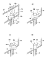
- 2 shows each embodiment of the flow regulating member applied to the vacuum degassing apparatus shown in FIG. 1
- FIG. 2 (a) is a partial sectional perspective view showing the first embodiment
- FIG. FIG. 2C is a partial cross-sectional perspective view showing the second embodiment
- FIG. 2C is a partial cross-sectional perspective view showing the third embodiment
- FIG. 2D is a partial cross-sectional perspective view showing the fourth embodiment.
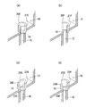
- FIG. 3 shows each embodiment of the rectifying member applied to the vacuum degassing apparatus shown in FIG. 1, FIG.
- FIG. 3 (a) is a partial cross-sectional perspective view showing the fifth embodiment
- FIG. FIG. 3C is a partial sectional perspective view showing the sixth embodiment
- FIG. 3C is a partial sectional perspective view showing the seventh embodiment
- FIG. 3D is a partial sectional perspective view showing the eighth embodiment.
- FIG. 4 shows each embodiment of the flow regulating member applied to the vacuum degassing apparatus shown in FIG. 1,
- FIG. 4 (a) is a partial sectional perspective view showing the ninth embodiment, and FIG.
- FIG.4 (c) is the fragmentary sectional perspective view which shows 11th Embodiment.
- FIG. 5 is a flowchart showing an example of a process according to the method for manufacturing a glass product according to the present invention.
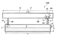
- FIG. 6 is a longitudinal sectional view showing a model structure of the vacuum degassing apparatus used for the simulation analysis of the example.
- FIG. 7A is a diagram showing the air flow analysis result of the example
- FIG. 7B is a diagram showing the air flow analysis result of the comparative example.
- FIG. 8 is a graph plotting the pressure in the upper space of the molten glass in the vacuum degassing tanks of Examples and Comparative Examples.
- FIG. 9 shows the flow rate of the gas (upstream exhaust gas) discharged from the reduced pressure defoaming tank to the atmosphere control unit through the outflow side connection passage and the inflow side connection passage from the reduced pressure defoaming tank. It is the graph which showed the flow volume of the gas (downstream exhaust gas) discharged
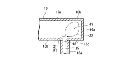
- FIG. 10 shows a conventional vacuum degassing apparatus in which the inflow side connection passage is connected to the atmosphere control unit, and a space is formed in the outer periphery of the atmosphere control unit, the space, the inflow side connection passage, and the vicinity of the opening. It is a figure which shows typically the behavior of the gas flow in.
- FIG. 1 is a longitudinal sectional view schematically showing an example structure of a vacuum degassing apparatus for molten glass according to the present invention.
- a vacuum degassing apparatus 100 shown in FIG. 1 is an apparatus used for a process of degassing the molten glass G supplied from the melting tank 1 and continuously supplying it to a molding apparatus 200 in a subsequent step.
- the vacuum degassing apparatus 100 of this embodiment has a metal, for example, stainless steel, vacuum housing 2 that can keep the inside of the vacuum degassing apparatus in a vacuum state during use.
- a decompression defoaming tank 3 is accommodated and disposed so that its long axis is oriented in the horizontal direction.
- the internal pressure of the vacuum degassing tank 3 is set to be less than atmospheric pressure, and the bubbles in the supplied molten glass G are floated and broken.
- a rising pipe 5 oriented in the vertical direction is connected to the lower surface on one end side of the vacuum degassing tank 3 via an introduction port 3a, and a lowering pipe 6 oriented in the vertical direction is connected to the lower surface on the other end side via an outlet port 3b. It is connected.
- the ascending pipe 5 and the descending pipe 6 are arranged so as to be able to communicate with each other through an inlet 2a or an outlet 2b formed on the bottom side of the decompression housing 2.
- the vacuum degassing apparatus 100 of this embodiment has an atmosphere control unit 16 connected to the vacuum degassing tank 3 by at least two connecting pipes 14A and 15A.
- the atmosphere control unit 16 has a hollow structure, has a width similar to that of the vacuum degassing tank 3, is accommodated and disposed above the vacuum degassing tank 3 in the vacuum housing 2, and has a central portion.
- An exhaust port 17 is provided for exhausting and depressurizing the atmosphere control unit 16.
- a connection passage 14 is formed inside the connection pipe 14A, and a connection passage 15 is formed inside the connection pipe 15A.
- the decompression housing 2 around the decompression deaeration tank 3, around the riser pipe 5, around the downcomer pipe 6, around the bottom part 16B and the side wall part 16D of the atmosphere control part 16, and around the connection pipe 14A And the connecting pipe 15A are provided with heat insulating materials 7, respectively.
- the decompression defoaming tank 3, the rising pipe 5, the descending pipe 6, the connecting pipes 14A and 15A, and the bottom 16B of the atmosphere control section 16 are provided.
- the outside of the side wall 16D is surrounded by the heat insulating material 7.
- the vacuum degassing tank 3 the rising pipe 5 and the descending pipe 6 are made of a refractory brick such as an electroformed brick or a hollow tubular shape made of platinum or a platinum alloy.
- the vacuum degassing tank 3 is a refractory brick hollow tube
- the vacuum degassing tank 3 is a refractory brick hollow tube having a rectangular cross section, and the inner shape of the molten glass channel is rectangular. It preferably has a cross section.
- the vacuum degassing tank 3 is a hollow tube made of platinum or a platinum alloy, it is preferable that the internal cross-sectional shape forming the flow path of the molten glass in the vacuum degassing tank 3 is circular or elliptical.
- the riser pipe 5 and the downfall pipe 6 are refractory brick hollow pipes
- the riser pipe 5 and the downfall pipe 6 are refractory brick hollow pipes having a circular cross section and a polygonal cross section including a rectangle, and molten glass.
- the internal cross-sectional shape forming the flow path has a circular cross section.
- the riser pipe 5 and the downfall pipe 6 are platinum or platinum alloy hollow pipes, it is preferable that the internal cross-sectional shape forming the flow path of the molten glass in the riser pipe 5 or the downfall pipe 6 is circular or elliptical. .
- the vacuum degassing apparatus 100 in the case of a large-sized apparatus that achieves a processing capacity of 200 tons / day or more, or a processing capacity of 500 tons / day or more, the vacuum degassing is performed with a refractory brick such as an electroformed brick. It is preferable that the tank 3 is configured.
- An extension outer tube 8 is attached to the lower end of the ascending tube 5
- an extension outer tube 9 is attached to the lower end of the descending tube 6, and the outer tubes 8 and 9 are made of platinum or a platinum alloy.
- the outer pipes 8 and 9 for extension are not provided separately, and are described as outer pipes 8 and 9 in FIG.
- the ascending pipe 5 and the descending pipe 6 may be integrally extended up to the portion where they are located.
- the description regarding the outer pipes 8 and 9 in the specification of the present application can be read and applied as a description regarding the ascending pipe and the descending pipe made of platinum or a platinum alloy.
- the ascending pipe 5 communicates with the bottom of one side of the vacuum degassing tank 3, and introduces the molten glass G from the melting tank 1 into the vacuum degassing tank 3. For this reason, the lower end (upstream end) 8a of the outer pipe 8 attached to the rising pipe 5 is fitted from the opening end of the upstream pit 12 connected to the melting tank 1 via the conduit 11, and the molten glass G in the upstream pit 12 is inserted. Soaked in Further, the downcomer 6 communicates with the bottom of the other side of the vacuum degassing tank 3 and guides the molten glass G after the vacuum degassing to the next processing tank (not shown).
- the lower end (downstream end) 9 a of the outer tube 9 attached to the downcomer pipe 6 is fitted into the opening end of the downstream pit 13 and is immersed in the molten glass G in the downstream pit 13.
- a molding apparatus 200 is connected to the downstream side of the downstream pit 13.
- the ascending pipe 5 constitutes a molten glass supply mechanism
- the descending pipe 6 constitutes a molten glass delivery mechanism.
- upstream and downstream mean upstream and downstream in the flow direction of the molten glass G flowing through the vacuum degassing apparatus 100.
- the outer tubes 8 and 9 are made of platinum or platinum alloy cylindrical tubes
- platinum alloys include platinum-gold alloys and platinum-rhodium alloys. It is done.
- reinforced platinum obtained by dispersing a metal oxide in platinum or a platinum alloy may be used.
- the metal oxide to be dispersed include a group 3, 4, or 13 metal oxide represented by Al 2 O 3 or ZrO 2 or Y 2 O 3 in the long periodic table.
- the vacuum housing 2 is vacuum-suctioned, and the atmosphere control unit 16 and the vacuum degassing tank 3 are exhausted from the exhaust port 17 to depressurize the vacuum housing 2. Maintain atmospheric pressure at a reduced pressure below atmospheric pressure.
- the atmosphere control unit 16 is connected to the internal space of the atmosphere control unit 16 and the upper space (the space above the molten glass container) of the molten glass G in the vacuum degassing tank 3. A path of the gas flow F flowing through the passages 14 and 15 is formed.
- the gas flow F circulates between the upper space of the molten glass G and the internal space of the atmosphere control unit 16, the gas flow is not necessarily circulated.
- the gas flow may consist of a flow discharged from the exhaust port 17 through the connection pipe 14A and a flow discharged from the exhaust port 17 through the connection pipe 15A.
- the gas flow is a flow discharged from the exhaust port 17 by the pressure reducing operation of the vacuum degassing tank, and is generated regardless of the presence or absence of the gas to be supplied.
- the temperature gradient in the vacuum degassing vessel 3 and the atmosphere control unit 16 also imparts a flow to the gas component from the molten glass G.
- the gas flow F includes a gas component generated from the molten glass G
- the vacuum degassing apparatus 100 includes a gas supply unit described later, in addition to the gas component from the molten glass G, the gas supply unit Contains supplied gas components.
- the atmosphere control unit 16 forms a path of the gas flow F flowing through the upper space of the molten glass G in the vacuum degassing vessel 3 and the internal space of the atmosphere control unit 16, and therefore the connection passages 14 and 15 are It is necessary to connect to the vacuum degassing tank 3 above the liquid surface of the molten glass G in the vacuum degassing tank 3. For this reason, as shown in FIG. 1, it is a preferable aspect to arrange
- connection passages 14 and 15 are connected to the vacuum degassing tank 3 above the liquid level of the molten glass G in the vacuum degassing tank 3, the atmosphere control unit 16 is connected to the vacuum degassing tank 3 side. You may arrange in the direction.
- connection pipes 14A and 15A are required. is there.
- the vacuum degassing tank 3 and the atmosphere control unit 16 are connected by two connecting pipes 14A and 15A, but the vacuum degassing is performed by three or more connecting pipes.
- the tank 3 and the atmosphere control unit 16 may be connected.
- the atmosphere controller 16 and the connecting pipes 14A and 15A are not conduits for the molten glass G, so the material thereof is not particularly limited.
- metal materials such as stainless steel, platinum and platinum alloys, fire resistance such as ceramics and alumina, etc. -Corrosion resistant materials can be used.
- the atmosphere control unit 16 and the connection passages 14 and 15 It is preferable to have a heating mechanism.
- the vacuum degassing apparatus 100 includes an upper space (a space above the molten glass container) of the molten glass G in the vacuum degassing tank 3, an inside of the connection passage 14, You may provide the gas supply means (illustration omitted) which supplies gas to the inside of the connection channel
- a gas flow F as shown in FIG. 1 can be formed by supplying gas so that Fd is generated. Further, the gas flowing into the internal space of the atmosphere control unit 16 so as to generate the gas flow Fb flowing from the downstream side to the upstream side, or the gas flowing from the internal space of the atmosphere control unit 16 to the connection passage 14 side. By supplying the gas so as to generate the flow Fc, a gas flow F as shown in FIG. 1 can be formed.
- a gas flow F as shown in FIG. 1 can be formed by supplying gas so that a gas flow Ff flowing from the upper space of G toward the connection passage 15 is generated.
- the gas flow F flowing through the upper space of the molten glass G in the vacuum degassing tank 3, the connection passages 14 and 15, and the atmosphere control unit 16 can be formed. If possible, only one gas supply means may be provided, or two or more gas supply means may be provided.
- the gas flowing through the upper space of the molten glass G (the space above the molten glass container), the connection passages 14 and 15, and the atmosphere controller 16 in the vacuum degassing tank 3.
- the gas component from the molten glass G is carried to the atmosphere control unit 16 by the gas flow F without staying.
- the gas component from the molten glass G carried to the atmosphere control unit 16 is discharged to the outside from the exhaust port 17.
- the gas flow F circulates, a part of the gas component from the molten glass G carried into the internal space of the atmosphere control unit 16 is carried by the gas flow F and the molten glass G in the vacuum degassing tank 3 Although there is a case of returning to the upper space, there is a gas flow F that circulates between the atmosphere control unit 16 of the molten glass G in the vacuum degassing tank 3 and the vacuum degassing tank 3, so that the gas component from the molten glass G The risk of stagnation is minimized.
- the gas component from the molten glass G is diluted with the supply gas from the gas supply means, so that the gas component from the molten glass G is defoamed in the process of being cooled. It is prevented from adhering in the apparatus 100 or adhering to the system after being discharged from the exhaust port 17.
- the vacuum degassing apparatus 100 of this embodiment stagnates the gas component F from the molten glass G by rectifying the gas flow F flowing through the upper space of the molten glass G in the vacuum degassing tank 3 and the atmosphere control unit 16. Therefore, the effect of vacuum degassing is excellent.
- the foam layer is enlarged due to excessive decompression, and the effect of decompression defoaming is significantly reduced.
- the gas component from the glass G is carried by the gas flow F without being retained, and is discharged to the outside from the exhaust port 17. Therefore, even if the degree of vacuum in the vacuum degassing tank 3 is higher than the conventional level, It becomes possible to suppress the enlargement of the layer. Therefore, the pressure reduction degree of the vacuum degassing tank 3 can be made higher than before (that is, the absolute pressure of the vacuum degassing tank 3 can be made lower than before), and the effect of vacuum degassing can be further enhanced. Can do.
- the gas flow F is formed above the molten glass G in order to eliminate the retention of gas components from the molten glass G. Therefore, when using a gas supply means, it is preferable that the gas supplied does not have a bad influence on molten glass, the glass product manufactured, and glass manufacturing equipment, especially a vacuum degassing apparatus. Therefore, it is preferable that the gas component supplied from the gas supply means does not contain corrosive or explosive gas.
- the gas satisfying the above include air, dry air, an inert gas such as N 2 and Ar, and a low molecular gas such as CO 2 . These gases may be used alone or as a mixed gas of two or more.
- the molten glass G in the vacuum degassing tank 11 is used. This is preferable because the effect of reducing the water vapor concentration in the upper atmosphere is expected. It is preferable that the water vapor concentration in the atmosphere above the molten glass G in the vacuum degassing tank 3 is reduced to 60 mol% or less.
- the low molecular gas used as the gas supplied from the gas supply means is preferably a gas whose oxygen concentration is lower than the oxygen concentration in the air.
- the low molecular gas used as the gas supplied from the gas supply means uses a gas having a lower oxygen concentration than the oxygen concentration in the air, so that when platinum and a platinum alloy are used as the material of the vacuum degassing tank 3, This is preferable because the oxidation of platinum can be suppressed, the life of the vacuum degassing tank 3 can be extended, and further, the generation of defects derived from platinum can be suppressed in glass products.
- the average velocity in the width direction of the gas flow F is not particularly limited as long as the retention of gas components from the molten glass G can be eliminated, but is preferably 0.0005 to 1.50 m / s, and preferably 0.001 to 0 More preferably, it is 2 m / s.
- the connection on the side where the gas flow F containing the gas component generated from the molten glass G in the atmosphere control unit 16 flows from the vacuum degassing tank 3 into the atmosphere control unit 16 is connected.
- a rectifying member 20 is provided around the opening 18 on the outlet side of the passage 15.
- the rectifying member 20 has a gas flow Fa in a region flowing into the atmosphere control unit 16 from the opening 18. It is provided to arrange the flow.
- the flow regulating member 20 will be described in detail.
- connection passage 15 on the side where the gas flow F flows into the atmosphere control unit 16 is referred to as an “inflow side connection passage 15”, and the connection passage 14 through which the gas flow F flows out of the atmosphere control unit 16 is referred to. It may be referred to as “outflow side connection passage 14”.
- connection pipe 15A forming the inflow side connection passage 15 may be referred to as “inflow side connection pipe 15A”
- connection pipe 14A forming the outflow side connection path 14 may be referred to as “outflow side connection pipe 14A”.
- the rectifying member 20 is provided around the opening 18 where the connecting pipe 15A communicates with the atmosphere control unit 16.
- the inflow side connecting pipe 15 ⁇ / b> A is connected to the atmosphere control unit 16 so as to be inside the outer peripheral side wall 16 a of the atmosphere control unit 16.
- the inflow side connecting pipe 15A can be provided at a position closer to the outer peripheral side wall 16a. However, when the outer peripheral side wall 16a of the atmosphere control unit 16 and the inflow side connecting pipe 15A are brought closer, the inflow side connecting pipe 15A and the atmosphere are connected.
- the thermal expansion coefficient of the heat insulating material 7 provided around the control unit 16 the thermal expansion coefficient of the material forming the inflow side connecting pipe 15A, and the thermal expansion coefficient of the material forming the atmosphere control unit 16 are different. In some cases, it may be difficult to maintain the structure of the vacuum degassing apparatus 100 at a high temperature during vacuum degassing. Therefore, as shown in FIG. 1, the inflow side connecting pipe 15 ⁇ / b> A is provided on the inner side of the outer peripheral side wall 16 a of the atmosphere control unit 16, and the outer peripheral space of the atmospheric control unit 16 (the outer peripheral side wall 16 a and the outer peripheral ceiling part).
- the outer peripheral space 19 is preferably formed.
- the inflow side connecting pipe 15A is more than the outer peripheral side wall 16a of the atmosphere control unit 16 If it is provided on the inner side, that is, if the space 19 is formed, it is also preferable in that the aggregates fall on the outer peripheral floor 16c and can be prevented from falling into the vacuum degassing tank 3.
- the outflow side connecting pipe 14A is also connected to the atmosphere control unit 16 so as to be inside the outer peripheral side wall 16a of the atmosphere control unit 16 with respect to the outer peripheral side wall on the other side.
- the inflow side connecting pipe 15A is connected to the atmosphere control unit 16, and the outer peripheral space of the atmosphere control unit 16 (the space surrounded by the outer peripheral side wall 16a, the outer peripheral ceiling 16b, and the outer peripheral floor 16c).
- 19 is preferable for the above-mentioned reason, but as shown in the examples described later, the present inventors conducted a simulation analysis of the behavior of the gas flow in the vicinity of the space 19, the inflow side connection passage 15 and the opening 18. Since the space 19 is formed, the gas flow F (updraft) that rises through the opening 18 is hindered by the vortex airflow generated in the space 19, and the flow of the gas flow F becomes unstable. found.
- FIG. 10 shows a conventional vacuum degassing apparatus in which the inflow side connecting pipe 15A is connected to the atmosphere control unit 16, and the outer peripheral space of the atmosphere control unit 16 (the outer peripheral side wall 16a, the outer peripheral ceiling 16b, and the outer peripheral floor
- FIG. 9 is a diagram schematically showing the behavior of the gas flow in the vicinity of the space 19, the inflow side connecting pipe 15 ⁇ / b> A, and the opening 18 when a space 19 surrounded by the portion 16 c is formed.
- the temperature of the atmosphere control unit 16 is lower than the temperature of the vacuum degassing tank 3 through which the molten glass G flows, and the ceiling 16A of the atmosphere control unit 16 and the floor of the atmosphere control unit 16 With 16B, the ceiling portion 16A has a lower temperature than the floor portion 16B, and the temperature difference is about 100 ° C., for example. For this reason, in the outer peripheral part ceiling part 16b of the atmosphere control part 16, and the outer peripheral part floor part 16c of the atmosphere control part 16, temperature of this outer peripheral part ceiling part 16b becomes lower than this outer peripheral part floor part 16c. Yes.
- the ascending air flow S1 which is the gas flow F rising the inflow side connection passage 15 from the vacuum degassing tank 3 flows into the atmosphere control unit 16 through the opening 18.
- a part of the air flows into the outer peripheral space 19 of the atmosphere control unit 16 and is cooled by the outer periphery ceiling portion 16b having a relatively low temperature in the atmosphere control portion 16, and descends toward the outer peripheral floor portion 16c. To do.
- a vortex air flow S 2 as shown in FIG. 10 is generated in the outer peripheral space 19 of the atmosphere control unit 16.
- FIG. 7B illustrates the space 19 and the inflow side when the inflow side connection passage 15 is connected to the atmosphere control unit 16 and the space 19 of the outer periphery of the atmosphere control unit 16 is formed in the embodiment described later. It is a figure which shows the result of having carried out the simulation analysis of the behavior of the gas flow in the connection passage 15 and the opening part 18 vicinity.
- the vortex air flow S2 from the outer peripheral space 19 is a gas flow (updraft) S1 flowing from the inflow side connection passage 15 into the atmosphere control unit 16 through the opening 18. The flow is obstructed.
- the vacuum degassing apparatus 100 of the present embodiment is generated from the molten glass G in the atmosphere control unit 16.
- the rectifying member 20 is provided around the opening 18 on the outlet side of the inflow side connection passage 15 on the side where the gas flow F containing the gas component flows into the atmosphere control unit 16 from the vacuum degassing tank 3.
- the rectifying member 20 is provided in order to suppress the vortex airflow S2 as shown in FIG. 10 from hindering the flow of the rising airflow S1, and includes the opening 18 and the outer peripheral space 19 of the atmosphere control unit 16.
- a rectifying wall portion 21 is provided for separating the two.
- FIG. 2A is a partial cross-sectional perspective view showing an embodiment of the rectifying member provided in the vacuum degassing apparatus 100 of the present embodiment and the vicinity of the rectifying member of the vacuum degassing apparatus 100 partially enlarged. is there.
- the rectifying member 20 shown in FIG. 2A is provided with a rectifying wall portion 21 that partitions the space 19 of the outer peripheral portion of the atmosphere control portion 16 and the opening 18 so as to cover the entire periphery of the opening 18. (That is, a cylindrical shape).
- An introductory part 23 for introducing gas from the opening 18 of the inflow-side rectifying member 15 into the inside of the rectifying member 20 is formed at the bottom of the tubular rectifying member 20.
- a lead-out part 24 for leading the gas introduced into the rectifying member 20 to the atmosphere control part 16 is formed.
- the rectifying wall portion 21 that partitions the space 19 and the opening 18 in the outer peripheral portion of the atmosphere control unit 16 flows into the opening 18 with the vortex airflow S 2 generated in the space 19. To suppress. Therefore, it is possible to prevent the rising airflow S1 flowing through the inflow side connection passage 15 from colliding with the vortex airflow S2 in the vicinity of the opening 18 and inhibiting the flow of the rising airflow S1.
- FIG. 7A shows an atmosphere control unit 16 in a case where a rectifying member 20 having the shape shown in FIG. 2A is provided around the opening 18 on the outlet side of the inflow side connection passage 15 in the embodiment described later. It is a figure which shows the result of having analyzed simulation of the behavior of the gas flow in the space 19 of the outer peripheral part, the inflow side connection channel
- the atmosphere control unit 16 is passed from the inflow side connection passage 15 through the opening 18.
- the inflowing gas flow F (ascending airflow S1) is not hindered by the vortex airflow S2 from the space 19, and the flow velocity of the gas flow F is stabilized.
- the vacuum degassing apparatus 100 has a configuration in which the flow straightening member 20 is provided around the opening 18 on the outlet side of the inflow side connection passage 15 of the atmosphere control unit 16, thereby reducing the pressure.
- the flow velocity of the gas flow F flowing through the upper space of the molten glass G in the defoaming tank 3 and the atmosphere control unit 16 is stabilized, and the stagnation of gas components from the molten glass G can be stably eliminated, and the vacuum defoaming performance The effect of reduced pressure defoaming can be improved.
- the opening size of the introduction portion 23 of the rectifying member 20, the opening size of the outlet portion 24, and the internal space of the rectifying member 20 do not hinder the flow of the gas flow F and stabilize the flow of the gas flow F. Therefore, it is preferable that the opening 18 is set to be larger than the dimension of the opening 18.
- the inner surface 22 of the rectifying wall portion 21 of the rectifying member 20 functions as a guide surface that guides the flow of the gas flow F (that is, forms a flow path of the gas flow F). Like the rectifying member 20 shown in FIG. 2A, the guide surface is formed so that the lead-out portion 24 is formed above the opening 18 and the gas flow F is guided vertically upward from the opening 18.
- the guide surface is formed so that the lead-out portion 24 is formed above the opening 18 and the gas flow F is guided vertically upward from the opening 18.
- the outlet portion 24 is formed so as to face the outflow side connection passage 14 side of the atmosphere control portion 16, and the gas flow F flows into the atmosphere control portion 16. It may be guided to flow from the side connection passage 15 side to the outflow side connection passage 14 side. If the guide surface which is the inner surface 22 of the rectifying wall portion 21 of the rectifying member 20 is set so as not to guide the gas flow F to the space 19 side, the melting in the vacuum degassing tank 3 as shown in FIG. A gas flow F that circulates in the upper space of the glass G and the atmosphere control unit 16 is formed.
- the rectifying member 20 is formed of a material excellent in heat resistance, and examples thereof include ceramic non-metallic inorganic materials and dense refractories.
- dense refractories include, for example, electrocast refractories such as alumina electrocast refractories, zirconia electrocast refractories, alumina-zirconia-silica electrocast refractories, and dense alumina refractories.
- dense fired refractories such as dense zirconia-silica refractories and dense alumina-zirconia-silica refractories.
- the maximum height h of the flow regulating member 20 is 1/4 ⁇ h / H ⁇ 3, where H is the indoor height of the atmosphere control unit 16 at the position where the opening 18 of the inflow side connection passage 15 is formed.
- / 4 is preferably set so as to satisfy the relationship of updraft, and it is preferable to set so as to satisfy the relationship of 1/3 ⁇ h / H ⁇ 2/3. It is more preferable because it does not inhibit.
- the dimension of the rectifying member 20 can be appropriately selected according to the vacuum degassing device to be used.
- the dimension of each component of the vacuum degassing apparatus of the present invention can be appropriately selected as necessary. An example of the dimensions of each component is shown below.
- the dimensions of the rectifying member 20 shown below can also be applied to the rectifying members 20B to 20L of the second to eleventh embodiments described later.
- the size of the vacuum degassing tank of the vacuum degassing apparatus of the present invention is not limited to whether the vacuum degassing tank is made of platinum, a platinum alloy, or a dense refractory. It can select suitably according to the shape of a defoaming tank.
- the vacuum degassing tank 3 as shown in FIG. 1 has a cylindrical shape, an example of the dimensions is as follows. ⁇ Length in the horizontal direction: 1-20m ⁇ Inner diameter: 0.2-3m (circular cross section)
- the wall thickness is preferably 4 mm or less, more preferably 0.5 to 1.2 mm.
- the vacuum degassing tank 3 is not limited to a cylindrical shape having a circular cross section, and may be a substantially circular shape having an elliptical shape or a semicircular cross sectional shape, or a cylindrical shape having a rectangular cross section.
- the riser pipe 5 and the downfall pipe 6 are made of platinum, platinum alloy, or dense fireproof, they can be appropriately selected according to the vacuum degassing apparatus to be used.
- examples of the dimensions of the ascending pipe 5 and the descending pipe 6 are as follows. Inner diameter: 0.05 to 0.8 m, more preferably 0.1 to 0.6 m -Length: 0.2-6m, more preferably 0.4-4m
- the wall thickness is preferably 0.4 to 5 mm, more preferably 0.8 to 4 mm.
- the dimension of the atmosphere control part 16 can be suitably selected according to the vacuum degassing apparatus to be used, especially the vacuum degassing tank 3, the example is as follows. Inner diameter: 0.1 to 3m, more preferably 0.1 to 2m -Length: 0.8-22m, more preferably 1-20m The indoor height H at the position where the opening 18 is formed: 0.1 to 3 m, more preferably 0.1 to 2 m The thickness of the atmosphere control unit 16 varies depending on the constituent materials, but when it is made of stainless steel, it is preferably 0.5 to 2 mm, more preferably 0.5 to 1.5 mm.
- the dimensions of the outflow side connection pipe 14A and the inflow side connection pipe 15A can be appropriately selected according to the vacuum degassing apparatus to be used, particularly the vacuum degassing tank 3, and examples thereof are as follows.
- Inner diameter 0.05 to 0.5 m, more preferably 0.05 to 0.3 m -Length: 0.1-1m, more preferably 0.1-0.8m
- the wall thickness of the outflow side connection pipe 14A and the inflow side connection pipe 15A varies depending on the constituent materials, but when it is made of stainless steel, it is preferably 0.5 to 2 mm, more preferably 0.5 to 1. 5 mm.
- Distance D 1 of the outer peripheral portion side walls 16a inner surface of the opening 18 (inlet side connecting the inner peripheral surface of the passage 15A) and atmosphere control unit 16 varies depending on the thickness of the inflow side connecting pipe 15A, 0.05 ⁇ 2m
- the thickness is preferably 0.05 to 1 m.
- the size of the rectifying member 20 varies depending on the size of the atmosphere control unit 16, the inner diameter of the inflow side connecting pipe 15A, the installation position (that is, the size and forming position of the opening 18), and the height h of the rectifying member 20 is As described above, the relationship with the indoor height H at the position where the opening 18 of the atmosphere control unit 16 is formed preferably satisfies 1/4 ⁇ h / H ⁇ 3/4, and 1/3 ⁇ h / H It is more preferable to satisfy ⁇ 2/3. Specifically, for example, the height h of the rectifying member 20 is preferably 0.03 to 2 m, and more preferably 0.05 to 1 m.
- the wall thickness of the rectifying member 20 varies depending on the constituent materials, but is preferably 1 to 50 mm, more preferably 2 to 30 mm.
- the dimensions of the introduction part 23, the lead-out part 24, and the internal space of the rectifying member 20 vary depending on the dimensions of the inflow side connecting pipe 15A and the opening 18, but the flow of the gas flow F from the opening 18 is not hindered.
- the dimensions of the introduction part 23, the lead-out part 24, and the internal space of the rectifying member 20 are preferably set to be larger than the dimension of the opening part 18.
- the inner diameter of the rectifying member 20 is preferably set to be 0 to 50% larger than the dimension of the opening 18, specifically, The inner diameter of the rectifying member 20 is preferably set to be 0 to 0.5 m larger than the dimension of the opening 18, and more preferably 0 to 0.2 m.
- the rectifying member provided in the vacuum degassing apparatus of the present invention is not limited to the cylindrical rectifying member 20 shown in FIG.
- another embodiment of the rectifying member in the vacuum degassing apparatus of the present invention will be described with reference to FIGS.
- the material, preferable shape, installation position, and the like thereof are the same as those described for the rectifying member 20 shown in FIG.
- FIG. 2 (b) to 2 (d) show another embodiment of the rectifying member applied to the vacuum degassing apparatus of the present invention
- FIG. 2 (b) shows the rectifying member of the second embodiment
- FIG. 2C is a partial cross-sectional perspective view
- FIG. 2C is a partial cross-sectional perspective view showing the rectifying member of the third embodiment
- FIG. 2D is a partial cross-sectional perspective view showing the rectifying member of the fourth embodiment.
- the baffle member 20B shown in FIG. 2 (b) has a rectangular cross-sectional shape, and has a quadrangular introduction portion 23B and a lead-out portion 24B.
- the opening 18 is partitioned from the space 19 by the rectifying wall 21B. It can suppress that an airflow inhibits the upward airflow which flows through the opening part 18 from the inflow side connection channel
- FIG. Therefore, as in the case where the flow regulating member 20 is provided, the flow of gas flow is stabilized and melted by applying the flow straightening member 20B shown in FIG. 2B to the vacuum degassing apparatus of the present invention.
- the retention of the gas component from the glass G can be stably eliminated, the variation in the vacuum degassing performance can be suppressed, and the effect of the vacuum degassing can be improved.
- the rectifying member 20C shown in FIG. 2 (c) has a triangular cross-sectional shape and includes a triangular introduction portion 23C and a lead-out portion 24C.
- the rectifying member 20C having the above structure is installed so as to surround the periphery of the opening 18, whereby the opening 18 is partitioned from the space 19 by the rectifying wall 21C, and the vortex from the space 19 is separated. It can suppress that an airflow inhibits the upward airflow which flows through the opening part 18 from the inflow side connection channel
- the rectifying member 20D shown in FIG. 2 (d) is a teardrop-shaped tubular section, and has a teardrop-shaped introduction portion 23D and a lead-out portion 24D.
- the opening 18 is separated from the space 19 by the curved flow straightening wall 21D of the flow straightening member 20D.
- FIG. 3 shows another embodiment of the rectifying member applied to the vacuum degassing apparatus of the present invention.
- FIG. 3 (a) is a partial sectional perspective view showing the rectifying member of the fifth embodiment.
- FIG. 3B is a partial cross-sectional perspective view showing the rectifying member of the sixth embodiment,
- FIG. 3C is a partial cross-sectional perspective view showing the rectifying member of the seventh embodiment, and
- FIG. 3D is the eighth embodiment. It is a fragmentary sectional perspective view which shows this rectification
- the rectifying member in the vacuum degassing apparatus of the present invention partitions the space 19 and the opening 18 on the outer periphery of the atmosphere control unit 16 and suppresses the vortex airflow from the space 19 from flowing into the opening 18. If it is possible, the effect of the present invention can be achieved even if the entire circumference of the opening 18 is not covered.
- a rectifying wall portion 21E is provided so as to surround the opening portion 18 so as to exclude a part of the opening portion 18 located on the side opposite to the space 19. It may be done.
- the rectifying member 20E shown in FIG. 3A has a C-shaped cross-sectional shape.
- the rectifying wall portion 21E having the C shape partitions the space 19 and the opening 18, the vortex from the space 19 is removed. It can suppress that an airflow inhibits the upward airflow which flows through the opening part 18 from the inflow side connection channel
- FIG. Therefore, as in the case where the flow straightening member 20 is provided, the flow of gas flow is stabilized and melted by applying the flow straightening member 20E shown in FIG.
- the retention of the gas component from the glass G can be stably eliminated, the variation in the vacuum degassing performance can be suppressed, and the effect of the vacuum degassing can be improved.
- the rectifying member in the vacuum degassing apparatus of the present invention is configured such that the rectifying member 20F shown in FIG. 3B covers the space 19 so as to cover at least a half circumference of the opening 18 on the side facing the space 19. If the rectifying wall portion 21F that partitions the opening portion 18 is provided, the vortex airflow from the space 19 can be prevented from flowing into the opening portion 18, and the effect of the present invention can be achieved. .
- the rectifying member 20G shown in FIG. 3C is a tubular shape having an introduction part 23G and a lead-out part 24G, and its upper surface is formed to descend from the space 19 side to the opposite side of the space 19, and the lead-out part
- the opening of 24G faces the outflow side connection passage 14 side in the atmosphere control unit 16.
- the flow straightening member 20G having the above-described structure so as to surround the periphery of the opening 18, the opening 18 is partitioned from the space 19 by the flow straightening wall 21G of the flow straightening member 20G. It is possible to suppress the vortex airflow from 19 from inhibiting the upward airflow that flows from the inflow side connection passage 15 through the opening 18.
- straightening member in the vacuum degassing apparatus of this invention is installed so that the derivation
- the rectifying member 20H shown in FIG. 3 (d) has a tubular shape having an introduction part 23H and a lead-out part 24H, and the upper part of the wall surface located on the opposite side to the space 19 is the wall part surrounding the periphery of the opening part 18. It has a partially excised shape. Also in the rectifying member 20H shown in FIG. 3D, the opening 18 is partitioned from the space 19 by the rectifying wall 21H of the rectifying member 20H, and the vortex airflow from the space 19 passes through the opening 18 from the inflow side connection passage 15. It is possible to suppress the upward airflow that flows through the airflow.
- FIG. 4 shows another embodiment of the rectifying member applied to the vacuum degassing apparatus of the present invention.
- FIG. 4 (a) is a partial sectional perspective view showing the rectifying member of the ninth embodiment.
- FIG. 4B is a partial sectional perspective view showing the rectifying member of the tenth embodiment, and
- FIG. 4C is a partial sectional perspective view showing the rectifying member of the eleventh embodiment.
- the straightening member 20J shown in FIG. 4A has a tubular shape in which the straightening member 20 shown in FIG. 2A is bent so that the lead-out portion faces in the direction opposite to the space 19.
- the inner surface 22J of the rectifying wall portion 21J that partitions the space 19 and the opening 18 is configured to cause a gas flow that flows into the rectifying member 20J through the opening 18 and the introducing portion 23J. It functions as a guide surface for guiding to the derivation unit 24J.
- the rectifying member 20K shown in FIG. 4B can also suppress the vortex airflow from the space 19 from inhibiting the upward airflow that flows from the inflow side connection passage 15 through the opening 18 as in the above embodiment.
- the flow straightening member 20K shown in FIG. 4B has a structure in which the guide surface formed by the inner surface 22J of the flow straightening wall portion 21J in the flow straightening member 20J shown in FIG. ing.
- the inner surface 22K of the rectifying wall portion 21K serves as a guide surface for guiding the gas flow that has flowed into the rectifying member 20K through the opening 18 and the introducing portion 23K to the outlet portion 24K. It is functioning.
- the rectifying member 20K shown in FIG. 4B can also suppress the vortex airflow from the space 19 from inhibiting the upward airflow that flows from the inflow side connection passage 15 through the opening 18 as in the above embodiment.
- the lead-out portion 24L is in a state where the cylindrical (tube shape) tube axis direction is inclined with respect to the vertical direction. It can also be opened in the direction opposite to the space 19.
- the inner surface 22L of the rectifying wall portion 21L serves as a guide surface that guides the gas flow that flows into the rectifying member 20L through the opening 18 and the introducing portion 23L to the outlet portion 24L. It is functioning.
- the flow direction of the gas flow formed above the molten glass G is not particularly limited as long as the retention of gas components from the molten glass can be eliminated.
- the gas flow may be a direction opposite to the flow direction of the gas flow F shown in FIG. 1, that is, a gas flow from the downstream side to the upstream side of the vacuum degassing tank 3.
- connection passage 15 provided on the downstream side of the ceiling portion of the vacuum degassing tank 3 becomes an outflow side connection passage forming a gas flow path from the atmosphere control unit 16 to the vacuum degassing tank 3, and the vacuum degassing tank 3
- the connection passage 14 provided on the upstream side of the ceiling portion serves as an inflow side connection passage that forms a passage for the gas flow flowing from the vacuum degassing vessel 3 to the atmosphere control unit 16. Therefore, when the flow direction (circulation direction) of the gas flow is opposite to the gas flow F shown in FIG. 1, the above-described rectifying member is provided around the opening formed by the connection passage 14 and the atmosphere control unit 16. do it.
- the inflow side connection passage is provided on the inner side of the outer peripheral side wall 16D of the atmosphere control unit 16, and the rectifying member is provided around the opening on the outlet side of the inflow side connection passage. It is possible to prevent the flow of the rising air flowing up the inflow side connection passage from being obstructed by the vortex airflow generated in the space formed on the outer peripheral portion on the outer peripheral side wall 16D side.
- the gas flow F of the same direction as the distribution direction of the molten glass G is formed over the whole longitudinal direction of the vacuum degassing tank 3, the gas component from molten glass is formed.
- a plurality of gas flows may be formed in the upper space of the molten glass G.
- the plurality of gas flows may be the same as the flow direction of the molten glass G, or may be in opposite directions.
- the positional relationship between the two connection passages 14 and 15 is the upstream side and the downstream side, but the positional relationship between the connection passages is not limited to this.
- the positional relationship between the two connection passages may be the front side and the back side of the drawing.
- the direction of the gas flow flowing through the vacuum degassing tank 3 and the atmosphere control unit 16 is a direction orthogonal to the direction of the gas flow F in the illustrated mode (the direction of the gas flow in the atmosphere control unit 16 is respectively The front side and back side of the drawing, or the back side and front side of the drawing).
- the direction of the gas flow F in the vacuum degassing tank 3 is a direction orthogonal to the moving direction of the molten glass G.
- the direction of the gas flow F above the molten glass G in the vacuum degassing tank 3 is the same as that of the molten glass G.
- the vacuum degassing tank has a shape with no significant difference in length in the vertical and horizontal directions (for example, When the planar shape of the vacuum degassing tank is square, hexagonal, octagonal, etc.), the direction of the gas flow F in the vacuum degassing tank 3 is a direction perpendicular to the moving direction of the molten glass G, The retention of gas components from the molten glass G can be eliminated.
- the gas flow F flowing through the upper space of the molten glass G in the vacuum degassing tank 3 and the atmosphere control unit 16 is used. Since it is only necessary to eliminate the retention of gas components from the molten glass G, it is not always necessary to generate the gas flow F during the vacuum degassing. As long as the stagnation of gas components from the molten glass G can be eliminated, the gas flow F may be periodically generated during the vacuum degassing. For example, the gas flow is generated at a rate of about 1 to 30 seconds every hour. F may be generated. In order to periodically generate the gas flow F, the gas flow F may be periodically supplied from a gas supply means (not shown).
- the vacuum degassing apparatus of the present invention may have a structure other than the above.
- a baffle plate for guiding the gas flow F downward may be provided inside the ceiling portion of the vacuum degassing tank 3.
- the molten glass G is supplied to the vacuum degassing tank 3 in a state where the inside of the vacuum degassing tank 3 is maintained in a predetermined reduced pressure state less than atmospheric pressure.
- the inside of the vacuum degassing tank 3 is depressurized to 51 to 613 hPa (38 to 460 mmHg).
- the inside of the vacuum degassing tank 3 is more preferably decompressed to 80 to 338 hPa (60 to 253 mmHg).
- the glass G to be degassed under reduced pressure using the vacuum degassing apparatus 100 of the present embodiment is not limited in terms of composition as long as it is a glass manufactured by a heat melting method. Therefore, alkali glass such as soda lime silica glass represented by soda lime glass or alkali borosilicate glass may be used.
- soda-lime glass used for plate glass for buildings or vehicles, it is expressed in terms of mass percentage on the basis of oxide, SiO 2 : 65 to 75%, Al 2 O 3 : 0 to 3%, CaO: 5 to 15%, MgO: 0 to 15%, Na 2 O: 10 to 20%, K 2 O: 0 to 3%, Li 2 O: 0 to 5%, Fe 2 O 3 : 0 to 3%, TiO 2 : 0 to 5%, CeO 2 : 0 to 3%, BaO: 0 to 5%, SrO: 0 to 5%, B 2 O 3 : 0 to 5%, ZnO: 0 to 5%, ZrO 2 : 0 to 5 %, SnO 2 : 0 to 3%, SO 3 : 0 to 0.3%.
- SiO 2 39 to 70%
- Al 2 O 3 3 to 25%
- B 2 O 3 1 in terms of mass percentage based on oxide. It is preferable to have a composition of up to 20%, MgO: 0 to 10%, CaO: 0 to 17%, SrO: 0 to 20%, BaO: 0 to 30%.
- a mixed alkali glass used for a substrate for plasma display it is expressed in terms of mass percentage on the basis of oxide, and SiO 2 : 50 to 75%, Al 2 O 3 : 0 to 15%, MgO + CaO + SrO + BaO + ZnO: 6 to 24 %, Na 2 O + K 2 O: preferably 6 to 24%.
- the apparatus for producing a glass product according to the present invention includes the aforementioned vacuum degassing apparatus 100 and a melting means (melting apparatus) for producing a molten glass by melting the glass raw material provided on the upstream side of the vacuum degassing apparatus 100. And a molding means (molding apparatus) 200 that molds the molten glass provided downstream of the vacuum degassing apparatus 100, and a slow cooling means (slow cooling apparatus) that gradually cools the glass after molding. It is.
- molding means, and a slow cooling means it is the range of a well-known technique.
- a glass raw material adjusted to have a desired composition is put into a melting tank, and a predetermined temperature according to the type of glass, for example, in the case of soda lime glass for buildings and vehicles, The glass raw material is melted by heating to about 1400 to 1600 ° C. to obtain a molten glass.
- the molding means include a molding apparatus using a float method, a fusion method, a download method, or the like.
- a forming means using a float bath for the float process is preferable because a high-quality glass plate having a wide range of thickness from thin glass to thick glass can be produced in large quantities.
- a slow cooling furnace having a mechanism for gradually lowering the temperature of the glass after forming is generally used.
- the mechanism for gradually lowering the temperature gradually cools the glass after being formed by supplying a heat amount whose output is controlled by a combustion gas or an electric heater to a required position in the furnace.
- FIG. 5 is a flowchart of one embodiment of the method for producing a glass product of the present invention.
- the glass product manufacturing method of the present invention is characterized by using the aforementioned vacuum degassing apparatus 100.
- the glass product manufacturing method of the present invention includes, as an example, a melting step K1 for manufacturing molten glass by melting the molten glass by the previous melting means of the aforementioned vacuum degassing apparatus 100, and the aforementioned vacuum degassing apparatus 100.
- the method for producing a glass product of the present invention is within the scope of known techniques, except that the above-described vacuum degassing apparatus 100 is used.
- the apparatus used in the glass product manufacturing method of the present invention is as described above.
- FIG. 5 in addition to the melting step, the forming step, and the slow cooling step, which are components of the glass product manufacturing method of the present invention, a cutting step used as necessary and other post-steps are also shown.
- an air flow analysis in the upper space of the molten glass G in the vacuum degassing tank is performed using the thermal fluid analysis software FLUENT (Fluent), and the upper space of the molten glass in the vacuum degassing tank and the atmosphere control unit Elimination of stagnation of gas components from the molten glass due to the gas flow flowing through (in this analysis, the circulating gas flow) was evaluated.
- a decompression degassing apparatus like the decompression defoaming apparatus 100B shown in FIG. supplying of the height d 2 38mm, at an angle of the downstream direction 45 degrees from the upstream 0.1 m) from the upstream end of the vacuum degassing vessel 3, the 1060 ° C.
- vacuum degassing apparatus 100B shown in FIG. 6 shows only the main parts near the vacuum degassing tank and the atmosphere control unit of the calculation model used for the simulation, and the same elements as those shown in FIG. A reference is attached.
- each part of the vacuum degassing apparatus 100B used as a model are as follows.
- Connection pipes 14A and 15A Overall length 0.8 m, inner diameter 0.3 m (cylindrical shape)
- the connecting pipe 14 ⁇ / b> A was positioned 0.1 m from the upstream end of the vacuum degassing tank 3 and 0.6 m from the upstream end of the atmosphere control unit 16.
- the opening 18 has a distance D 1 of the from the inner wall of the downstream end portion of the atmosphere control unit 16 and 0.6 m.
- Exhaust port 17 Inner diameter 0.05 m.
- the atmosphere control unit 16 was provided on the ceiling in the center in the longitudinal direction.
- connection passage inflow side connection passage
- the straightening member 20 was installed by its own weight.
- the simulation analysis was performed under the same conditions as in the example except that the rectifying member was not installed.
- FIG. 7 shows the air flow analysis results of the atmosphere control unit 16 in the vicinity of the connection passage 15 of the example and the comparative example.
- FIG. 7A is a diagram showing the air flow analysis result of the example
- FIG. 7B is a diagram showing the air flow analysis result of the comparative example.
- the inflow side connection passage 15 passes through the opening 18.
- the gas flow S1 flowing into the atmosphere control unit 16 is not disturbed by the vortex air flow S2, and forms a stable flow.
- the vortex airflow S2 from the outer peripheral space is a gas flow S1 that flows from the inflow side connection passage 15 into the atmosphere control unit 16 through the opening 18.
- the rise is inhibited.
- the strength of the vortex airflow S2 changes depending on the strength of the ascending airflow S1, the ambient temperature environment, and the like, the flow of the ascending airflow S1 becomes unstable in such a situation, and the gas flow F is also unsatisfactory due to this. It becomes stable.
- the reduced pressure defoaming apparatus according to the present invention provided with the rectifying member stabilizes the flow rate of the gas flow circulating through the upper space of the molten glass in the reduced pressure defoaming tank and the atmosphere control unit.
- the retention of gas components from the glass can be stably eliminated, the variation in the vacuum degassing performance can be suppressed, and the effect of the vacuum degassing can be improved.
- FIG. 8 is a graph in which the pressure in the upper space of the molten glass G in the vacuum degassing vessel 3 is plotted from the upstream side to the downstream side for Examples and Comparative Examples.
- the horizontal axis is a coordinate (normalized coordinate) in which the position from the upstream end (upstream end) of the vacuum degassing tank is normalized with respect to the total length of the vacuum degassing tank 3, and the vertical axis is a comparison. It is the pressure (normalized pressure) normalized with the pressure at the upstream end of the upper space of the molten glass G in the vacuum degassing vessel 3 in the example as 1. From the result of FIG.
- the pressure difference between the upstream end and the downstream end of the upper space of the molten glass G in the vacuum degassing vessel 3 is larger than in the comparative example. It can be seen that the flow (circulation) state of the gas flow in the upper space of the molten glass G is good.
- the pressure difference between the upstream end and the downstream end of the upper space of the molten glass G in the vacuum degassing vessel 3 is small, the flow (circulation) of the gas flow in the upper space of the molten glass G is I understand that it is weak. As shown in FIG.
- FIG. 9 shows the flow rate of the gas (upstream exhaust gas) discharged from the vacuum degassing tank 3 to the atmosphere control unit 16 via the connection passage 14 and the inflow from the vacuum degassing tank 3 for the example and the comparative example.
- 4 is a graph showing the flow rate of gas (downstream exhaust gas) discharged to the atmosphere control unit 16 through the side connection passage 15.
- the discharge flow rates of the respective gases are standardized with the flow rate of the downstream exhaust gas of the example being taken as 1. From the result of FIG. 9, in the embodiment according to the present invention in which the rectifying member 20 is provided, the flow rate of the upstream exhaust gas is negative, that is, the gas flow from the atmosphere control unit 16 to the vacuum degassing tank 3 through the connection passage 14.
- the gas flow (circulation) condition is good.
- the flow rate of the upstream exhaust gas is positive, that is, the gas flow flows from the decompression defoaming tank 3 to the atmosphere control unit 16 through the connection passage 14, and in the upper space of the molten glass G It can be seen that the flow rate of the gas flowing from the upstream side to the downstream side decreases and the flow (circulation) of the gas flow is weak.
- the vacuum degassing apparatus according to the present invention provided with the flow straightening member stabilizes the flow velocity of the gas flow flowing through the upper space of the molten glass in the vacuum degassing tank and the atmosphere control unit, The retention of gas components from the glass can be stably eliminated, the variation in the vacuum degassing performance can be suppressed, and the effect of the vacuum degassing can be improved.
- the effect of vacuum degassing can be improved, and a high-quality glass product can be produced with high productivity.
- the vacuum degassing apparatus, the vacuum degassing method, the glass product manufacturing apparatus, and the glass product manufacturing method of the present invention are used for building materials, vehicles, flat panel displays such as liquid crystal display devices, plasma display devices, and organic EL display devices. It can be used for manufacturing glass products for optical, optical, medical, and other purposes.
- the entire contents of the specification, claims, drawings, and abstract of Japanese Patent Application No. 2010-172230 filed on July 30, 2010 are incorporated herein as the disclosure of the present invention. .
Landscapes
- Chemical & Material Sciences (AREA)
- Engineering & Computer Science (AREA)
- Materials Engineering (AREA)
- Organic Chemistry (AREA)
- Glass Melting And Manufacturing (AREA)
- Degasification And Air Bubble Elimination (AREA)
- Waste-Gas Treatment And Other Accessory Devices For Furnaces (AREA)
Abstract
Description
前記減圧脱泡装置は、内部が所定の減圧度に保持された減圧脱泡槽内に溶融ガラスを通過させることにより、溶融ガラス内に含まれる気泡を比較的短時間に成長させ、大きく成長した気泡の浮力を利用して気泡を溶融ガラスの表面に浮上させ、溶融ガラスの表面で気泡を破泡させることで、効率良く溶融ガラスから気泡を除去する装置である。
本発明は、上述の減圧脱泡装置を用いる溶融ガラスの減圧脱泡方法、ガラス製品の製造装置およびガラス製品の製造方法の提供を目的とする。
すなわち、本発明は、内部の気圧が大気圧未満に設定され、供給された溶融ガラス中の泡を浮上および破泡させる減圧脱泡槽を具備する溶融ガラスの減圧脱泡装置であって、少なくとも2つの接続通路により前記減圧脱泡槽の溶融ガラス収容部より上の空間と接続される中空構造の雰囲気制御部と、前記雰囲気制御部に形成された減圧用の排気口と、が設けられており、前記減圧脱泡槽から前記雰囲気制御部へと溶融ガラスから発生したガスが流れる流入側接続通路の出口側の開口部周囲に、前記ガスの流れを整える整流部材が設けられてなる溶融ガラスの減圧脱泡装置を提供する。
本発明の減圧脱泡装置において、前記整流部材が、前記流入側接続通路の出口側の開口部の少なくとも半周を覆って該開口部と前記雰囲気制御部の外周部との間を仕切る整流壁部を備えてなることが好ましい。
本発明の減圧脱泡装置において、前記整流部材の前記整流壁部内面に、前記減圧脱泡槽から前記流入側接続通路の出口側の開口部を介して前記雰囲気制御部へと流れるガスの流れを前記雰囲気制御部から減圧脱泡槽に通じる流出側接続通路側に誘導する案内面が形成されてなることが好ましい。
本発明の減圧脱泡装置において、前記整流部材の前記整流壁部が、前記流入側接続通路の出口側の開口部の全周を囲むように形成されてなることが好ましい。
本発明の減圧脱泡装置において、前記整流部材の形状が管状であることが好ましい。
本発明の減圧脱泡装置において、前記流入側接続通路の出口側の開口部が形成された位置における前記雰囲気制御部の室内の高さをHとし、前記整流部材高さの最大値をhとしたとき、1/4≦h/H≦3/4の関係を満たすことが好ましい。
本発明の減圧脱泡装置において、前記減圧脱泡槽の溶融ガラス収容部より上の空間内、前記少なくとも2つの接続通路の内部、または前記雰囲気制御部の内部のいずれかにガス供給手段が設けられてなることが好ましい。
本発明の減圧脱泡装置において、前記減圧脱泡槽と前記雰囲気制御部を囲い真空吸引されて内部が減圧される減圧ハウジングと、この減圧ハウジング内に設けられ、溶融ガラスの減圧脱泡を行うための減圧脱泡槽と、該減圧脱泡槽に溶融ガラスを供給するための供給機構と、脱泡後の溶融ガラスを次工程に送るための送出機構とを具備してなることが好ましい。
さらに、本発明は、上記した減圧脱泡装置と、該減圧脱泡装置よりも上流側に設けられたガラス原料を溶融して溶融ガラスを製造する溶融手段と、前記減圧脱泡装置よりも下流側に設けられた溶融ガラスを成形する成形手段と、成形後のガラスを徐冷する徐冷手段とを備えたガラス製品の製造装置を提供する。
さらにまた、本発明は、上記した減圧脱泡装置により溶融ガラスを脱泡処理する工程と、前記減圧脱泡装置よりも上流側でガラス原料を溶融して溶融ガラス製造する溶融工程と、前記減圧脱泡装置よりも下流側で溶融ガラスを成形する成形工程と、成形後のガラスを徐冷する徐冷工程とを含むガラス製品の製造方法を提供する。本発明のガラス製品の製造方法は、上記した減圧脱泡装置により前記減圧脱泡槽から前記雰囲気制御部へと溶融ガラスから発生したガスが流れる流入側接続通路の出口側の開口部周囲に設けた前記整流部材によって前記ガスの流れを整えて溶融ガラスを脱泡処理する工程と、前記減圧脱泡装置よりも上流側でガラス原料を溶融して溶融ガラスを製造する溶融工程と、前記減圧脱泡装置よりも下流側で溶融ガラスを成形する成形工程と、成形後のガラスを徐冷する徐冷工程とを含むことが好ましい。
本発明の減圧脱泡方法は、上述の減圧脱泡装置を用いることにより、優れた減圧脱泡の効果を実現できる。
また、上述の減圧脱泡装置を用いるガラス製品の製造装置と製造方法であるならば、高品質のガラス製品を提供できる。
図1は本発明に係る溶融ガラスの減圧脱泡装置の一例構造を模式的に示す縦断面図である。図1に示す減圧脱泡装置100は、溶融槽1から供給される溶融ガラスGを減圧脱泡して、後工程の成形装置200に連続的に供給するプロセスに用いられる装置である。
上昇管5および下降管6が白金製または白金合金製の中空管である場合、上昇管5または下降管6における溶融ガラスの流路をなす内部断面形状が円形または楕円形を有することが好ましい。
なお、減圧脱泡装置100において、200トン/日以上の処理能力、あるいは500トン/日以上の処理能力に達成するような大型の装置の場合、電鋳レンガのような耐火レンガにより減圧脱泡槽3が構成されていることが好ましい。
なお、上昇管5および下降管6が白金製または白金合金製の中空管である場合、延長用の外管8、9を別途設けることなく、図1において外管8、9と記載されている部分まで上昇管5と下降管6が一体的に延長された構造とされていても良い。このような構造とする場合、以下本願明細書における外管8、9に関する説明は、白金製または白金合金製の上昇管および下降管に関する記載として読み替えて適用できる。
また、下降管6は減圧脱泡槽3の他側底部に連通され、減圧脱泡後の溶融ガラスGを次の処理槽(図示略)に導出する。このため、下降管6に取り付けられた外管9の下端(下流端)9aは、下流ピット13の開口端に嵌入され、下流ピット13内の溶融ガラスGに浸漬されている。また、下流ピット13の下流側に成型装置200が接続されている。以上説明の減圧脱泡装置100においては、上昇管5が溶融ガラスの供給機構を構成し、下降管6が溶融ガラスの送出機構を構成する。
なお、本明細書において、「上流」および「下流」といった場合、減圧脱泡装置100を流通する溶融ガラスGの流動方向における上流および下流を意味する。
ここで、雰囲気制御部16は、減圧脱泡槽3内の溶融ガラスGの上部空間と該雰囲気制御部16の内部空間とを流れるガス流Fの経路をなすため、接続通路14、15は、減圧脱泡槽3内の溶融ガラスGの液面よりも上方で減圧脱泡槽3と接続する必要がある。このため、図1に示すように、雰囲気制御部16を減圧脱泡槽3の上方に配置することは好ましい態様である。ただし、接続通路14、15が減圧脱泡槽3内の溶融ガラスGの液面よりも上方で減圧脱泡槽3と接続されるのであれば、雰囲気制御部16を減圧脱泡槽3の側方に配置してもよい。
また、減圧脱泡槽3に流入するガス流Fの温度が低いと、減圧脱泡槽3内の溶融ガラスGに悪影響を及ぼすおそれがあるため、雰囲気制御部16、および接続通路14、15は、加熱機構を有することが好ましい。但し、雰囲気制御部16、および、接続通路14、15の全てに加熱機構を設けることは必ずしも必要ではなく、少なくとも、減圧脱泡槽3にガス流Fが流入する側の接続管(図1の場合、接続通路14の周囲)に加熱機構を設ければ、減圧脱泡槽3に温度が低いガス流Fが流入して、減圧脱泡槽3内の溶融ガラスGに悪影響を及ぼすおそれを解消することができる。
本実施形態の減圧脱泡装置100は、減圧脱泡槽3内の溶融ガラスGの上部空間と雰囲気制御部16とを流れるガス流Fを整流することにより、溶融ガラスGからのガス成分の滞留が解消されるため、減圧脱泡の効果に優れている。
また、溶融ガラスGからのガス成分が滞留すると、過減圧による泡層の肥大化が起こり、減圧脱泡の効果が大幅に低下してしまうが、本実施形態の減圧脱泡装置100では、溶融ガラスGからのガス成分が滞留することなく、ガス流Fによって運ばれ、排気口17から外部に放出されるため、減圧脱泡槽3の減圧度を従来よりも高くしても過減圧による泡層の肥大化がより抑制できるようになる。したがって、減圧脱泡槽3の減圧度を従来よりも高くすることができ(すなわち、減圧脱泡槽3の絶対圧を従来よりも低くすることができ)、減圧脱泡の効果をより高めることができる。
上記を満足するガスとしては、大気、乾燥空気、N2やArのような不活性ガス、CO2等の低分子ガスが挙げられる。これらのガスは単独で使用してもよく、2種以上の混合ガスとして使用してもよい。
減圧脱泡槽3内の溶融ガラスG上方の雰囲気の水蒸気濃度は、60mol%以下に低減されることが好ましい。該雰囲気の水蒸気濃度を60mol%以下とすることにより、減圧脱泡槽3内の溶融ガラス表面の泡層が肥大化して突沸が生じることを防止でき、減圧脱泡の効果をさらに向上させることができる。
以下、整流部材20について詳細に説明する。なお、以下の説明において、ガス流Fが雰囲気制御部16へと流入する側の接続通路15を「流入側接続通路15」と称し、ガス流Fが雰囲気制御部16より流出する接続通路14を「流出側接続通路14」と称することがある。また、流入側接続通路15を形成する接続管15Aを「流入側接続管15A」と称し、流出側接続通路14を形成する接続管14Aを「流出側接続管14A」と称することがある。
整流部材20は、図10に示すような渦気流S2が上昇気流S1の流れを阻害することを抑制するために設けられるものであり、開口部18と雰囲気制御部16の外周部の空間19とを区切る整流壁部21を備える。
図2(a)に示す整流部材20において、雰囲気制御部16の外周部の空間19と開口部18とを仕切る整流壁部21は、空間19で生じた渦気流S2が開口部18へと流入することを抑制する。そのため、流入側接続通路15を流れる上昇気流S1が、開口部18付近で該渦気流S2とぶつかり合い、上昇気流S1の流れが阻害されることを防ぐことができる。
この結果より明らかなように、本実施形態の減圧脱泡装置100は、雰囲気制御部16の流入側接続通路15の出口側の開口部18周囲に整流部材20を設ける構成とすることにより、減圧脱泡槽3内の溶融ガラスGの上部空間と雰囲気制御部16とを流れるガス流Fの流速が安定化され、溶融ガラスGからのガス成分の滞留を安定して解消でき、減圧脱泡性能のバラつきを抑制して、減圧脱泡の効果を向上させることができる。
整流部材20の整流壁部21の内面22は、ガス流Fの流れを誘導する(すなわち、ガス流Fの流路をなす)案内面として機能する。案内面は、図2(a)に示す整流部材20のように、導出部24が開口部18の上方に形成され、ガス流Fを開口部18から鉛直方向上方に誘導するように形成されていてもよいし、後述の図4に示す実施形態のように、導出部24が雰囲気制御部16の流出側接続通路14側を向くように形成され、ガス流Fが雰囲気制御部16内を流入側接続通路15側から流出側接続通路14側へと流れるように誘導してもよい。整流部材20の整流壁部21の内面22である案内面が、ガス流Fを空間19側へと誘導しないように設定されていれば、図1に示すような減圧脱泡槽3内の溶融ガラスGの上部空間と雰囲気制御部16とを循環するガス流Fが形成される。
整流部材20の寸法は、使用する減圧脱泡装置に応じて適宜選択することができる。本発明の減圧脱泡装置の各構成要素の寸法は、必要に応じて適宜選択することができる。以下に各構成要素の寸法の一例を示す。なお、以下に示す整流部材20の寸法は、後述する第2~第11の実施形態の整流部材20B~20Lにも適用できる。
本発明の減圧脱泡装置の減圧脱泡槽の寸法は、減圧脱泡槽が白金製もしくは白金合金製、または緻密質耐火物製であるかによらず、使用する減圧脱泡装置や、減圧脱泡槽の形状に応じて適宜選択することができる。図1に示すような減圧脱泡槽3が円筒形状である場合、その寸法の一例は以下の通りである。
・水平方向における長さ:1~20m
・内径:0.2~3m(断面円形)
減圧脱泡槽3が白金製もしくは白金合金製である場合、肉厚は4mm以下であることが好ましく、より好ましくは0.5~1.2mmである。
減圧脱泡槽3は、断面円形の円筒形状のものに限定されず、断面形状が楕円形や半円形状の略円形状のものや、断面が矩形の筒形状のものであってもよい。
上昇管5および下降管6は、白金製もしくは白金合金製、または緻密質耐火性であるかによらず、使用する減圧脱泡装置に応じて適宜選択することができる。たとえば、図1に示す減圧脱泡装置100の場合、上昇管5および下降管6の寸法の一例は以下の通り。
・内径:0.05~0.8m、より好ましくは0.1~0.6m
・長さ:0.2~6m、より好ましくは0.4~4m
上昇管5および下降管6が白金製もしくは白金合金製である場合、肉厚は0.4~5mmであることが好ましく、より好ましくは0.8~4mmである。
雰囲気制御部16の寸法は、使用する減圧脱泡装置、特に減圧脱泡槽3に応じて適宜選択することができるが、その一例は以下の通りである。
・内径:0.1~3m、より好ましくは0.1~2m
・長さ:0.8~22m、より好ましくは1~20m
・開口部18の形成位置における室内高さH:0.1~3m、より好ましくは0.1~2m
雰囲気制御部16の肉厚は、構成材料によっても異なるが、ステンレス鋼製である場合、0.5~2mmであることが好ましく、より好ましくは0.5~1.5mmである。
流出側接続管14A、流入側接続管15Aの寸法は、使用する減圧脱泡装置、特に減圧脱泡槽3に応じて適宜選択することができるが、その一例は以下の通りである。
・内径:0.05~0.5m、より好ましくは0.05~0.3m
・長さ:0.1~1m、より好ましくは0.1~0.8m
流出側接続管14Aおよび流入側接続管15Aの肉厚は、構成材料によっても異なるが、ステンレス鋼製である場合、0.5~2mmであることが好ましく、より好ましくは0.5~1.5mmである。
開口部18(流入側接続通路15Aの内周面)と雰囲気制御部16の外周部側壁16a内面との距離D1は、流入側接続管15Aの肉厚によっても異なるが、0.05~2mであることが好ましく、より好ましくは0.05~1mである。
整流部材20の寸法は、雰囲気制御部16の寸法、流入側接続管15Aの内径や設置位置(すなわち、開口部18の寸法や形成位置)などにより異なるが、整流部材20の高さhは、前述のように、雰囲気制御部16の開口部18の形成位置における室内高さHとの関係が、1/4≦h/H≦3/4を満たすことが好ましく、1/3≦h/H≦2/3を満たすことがより好ましい。具体的には、たとえば、整流部材20の高さhは0.03~2mであることが好ましく、より好ましくは0.05~1mである。
整流部材20の肉厚は、構成材料によっても異なるが、1~50mmが好ましく、より好ましくは2~30mmである。
整流部材20の導入部23、導出部24およびその内部空間の寸法は、流入側接続管15Aおよび開口部18の寸法などにより異なるが、開口部18からのガス流Fの流れを妨げないように、整流部材20の導入部23、導出部24および内部空間の寸法を、開口部18の寸法よりも大きくなるように設定することが好ましい。一例として、図2(a)に示す筒状(管状)の整流部材20の場合、整流部材20の内径を開口部18の寸法よりも0~50%大きく設定することが好ましく、具体的には、整流部材20の内径を開口部18の寸法よりも0~0.5m大きく設定することが好ましく、0~0.2m大きく設定することがより好ましい。
たとえば、図3(a)に示す整流部材20Eのように、開口部18のうち空間19とは反対側に位置する部分の一部を除くように開口部18を囲んで整流壁部21Eが設けられていてもよい。図3(a)に示す整流部材20Eは、横断面形状がC形状であるが、このC形状をなす整流壁部21Eが空間19と開口部18とを仕切っているため、空間19からの渦気流が、流入側接続通路15より開口部18を介して流動する上昇気流を阻害することを抑制できる。したがって、前記した整流部材20を設けた場合と同様に、本発明の減圧脱泡装置に図3(a)に示す整流部材20Eを適用することにより、ガス流の流れを安定化させて、溶融ガラスGからのガス成分の滞留を安定して解消でき、減圧脱泡性能のバラつきを抑制して、減圧脱泡の効果を向上させることができる。
また、本発明の減圧脱泡装置は、上記以外の構造を有していてもよい。たとえば、溶融ガラスGの表面(液面)近くにガス流Fを形成するため、減圧脱泡槽3の天井部の内側にガス流Fを下方に誘導するための邪魔板を設けてもよい。
減圧脱泡装置100にあっては、減圧脱泡槽3の内部を大気圧未満の所定の減圧状態に保持した状態で、減圧脱泡槽3に溶融ガラスGを供給する。たとえば、減圧脱泡槽3は、その内部を51~613hPa(38~460mmHg)に減圧されている。減圧脱泡槽3の内部は、80~338hPa(60~253mmHg)に減圧されていることがより好ましい。
本実施形態の減圧脱泡装置100を用いて減圧脱泡するガラスGは、加熱溶融法により製造されるガラスである限り、組成的には制約されない。従って、ソーダライムガラスに代表されるソーダライムシリカ系ガラスやアルカリホウケイ酸ガラスのようなアルカリガラスであっても良い。
プラズマディスプレイ用の基板に使用される混合アルカリ系ガラスの場合には、酸化物基準の質量百分率表示で、SiO2:50~75%、Al2O3:0~15%、MgO+CaO+SrO+BaO+ZnO:6~24%、Na2O+K2O:6~24%、という組成を有することが好ましい。
本発明のガラス製品の製造方法は、前述の減圧脱泡装置100を用いることを特徴とする。本発明のガラス製品の製造方法は、一例として、前述の減圧脱泡装置100の前段の溶融手段により溶融ガラスを溶融して溶融ガラスを製造する溶融工程K1と、前述の減圧脱泡装置100により溶融ガラスの減圧脱泡を行う脱泡工程K2と、前述の減圧脱泡装置100よりも下流側で溶融ガラスを成形する成形工程K3と、その後工程において溶融ガラスを徐冷する徐冷工程K4と、徐冷後のガラスを切断する切断工程K5と、ガラス製品K6を得るガラス製品の製造方法である。
・減圧脱泡槽3:全長L1=10m、高さd1=1m(断面半円形状)、溶融ガラスGの上部空間の高さd3=0.5m
・雰囲気制御部16:全長L2=11m、高さH=2m(円筒形状)
・接続管14A、15A:全長0.8m、内径0.3m(円筒形状)
接続管14Aは、減圧脱泡槽3の上流側端部から0.1m、および雰囲気制御部16の上流側端部から0.6mの位置とした。接続管15Aは、減圧脱泡槽3の下流側端部から0.1mの位置とし、開口部18は雰囲気制御部16の下流側端部の内壁からの距離D1を0.6mとした。
・排気口17:内径0.05m。雰囲気制御部16の長手方向中央の天井部に設けた。
気流解析には、非反応化学種の輸送モデル、標準k-εモデル、標準壁関数を採用した。入口拡散、拡散エネルギー、および減圧脱泡槽3内での溶融ガラスGの動きについては考慮せず、その他の設定パラメータはデフォルト値を使用した。気流解析の流体物性は、FLUENTデータベース内のN2および揮散H2Oからなる混合物の値(下記)を用いた。
・熱伝導率:0.0454[W/m・K]
・質量拡散係数:2.88×10⁻⁵[m2/s]
・密度:ρ=pMw/RT(非圧縮性理想気体方程式)
・比熱:cp=ΣiYjcp,i(化学種による比熱の質量分率平均式)[J/kg・K]
減圧脱泡槽3内の溶融ガラスGからは、SO3、O2、B2O3、H2O等、複数のガスが揮散すると考えられるが、本解析では便宜上H2Oのみが溶融ガラスGの表面から垂直上向きに体積流量14.55NL/minで揮散すると仮定した。
図6および図2(a)に示すように、接続通路(流入側接続通路)15の開口部18の周囲に、肉厚1.0mm、内径0.3m、高さhを1m(円筒形状)とした整流部材20を、自重により設置した。
(比較例)
整流部材を設置しないこと以外は、実施例と同じ条件でシミュレーション解析をした。
なお、2010年7月30日に出願された日本特許出願2010-172230号の明細書、特許請求の範囲、図面及び要約書の全内容をここに引用し、本発明の開示として取り入れるものである。
Claims (15)
- 内部の気圧が大気圧未満に設定され、供給された溶融ガラス中の泡を浮上および破泡させる減圧脱泡槽を具備する溶融ガラスの減圧脱泡装置であって、
少なくとも2つの接続通路により前記減圧脱泡槽の溶融ガラス収容部より上の空間と接続される中空構造の雰囲気制御部と、前記雰囲気制御部に形成された減圧用の排気口と、が設けられており、
前記減圧脱泡槽から前記雰囲気制御部へと溶融ガラスから発生したガスが流れる流入側接続通路の出口側の開口部周囲に、前記ガスの流れを整える整流部材が設けられてなる溶融ガラスの減圧脱泡装置。 - 前記流入側接続通路が、前記雰囲気制御部の外周部より内側において、減圧脱泡槽の溶融ガラス収容部の上部空間と前記雰囲気制御部との間で接続されてなる請求項1に記載の溶融ガラスの減圧脱泡装置。
- 前記整流部材が、前記流入側接続通路の出口側の開口部の少なくとも半周を覆って該開口部と前記雰囲気制御部の外周部との間を仕切る整流壁部を備えてなる請求項1または2に記載の溶融ガラスの減圧脱泡装置。
- 前記整流部材の前記整流壁部内面に、前記減圧脱泡槽から前記流入側接続通路の出口側の開口部を介して前記雰囲気制御部へと流れるガスの流れを前記雰囲気制御部から減圧脱泡槽に通じる流出側接続通路側に誘導する案内面が形成されてなる請求項3に記載の溶融ガラスの減圧脱泡装置。
- 前記整流部材の前記整流壁部が、前記流入側接続通路の出口側の開口部の全周を囲むように形成されてなる請求項3または4に記載の溶融ガラスの減圧脱泡装置。
- 前記整流部材が、前記流入側接続通路の出口側の開口部からのガスを該整流部材内部に導入する導入部と、該開口部から該整流部材内部に導入されたガスを前記雰囲気制御部へと導出する導出部とを備えてなる請求項1~5のいずれか一項に記載の溶融ガラスの減圧脱泡装置。
- 前記整流部材の形状が管状である請求項1~6のいずれか一項に記載の溶融ガラスの減圧脱泡装置。
- 前記流入側接続通路の出口側の開口部が形成された位置における前記雰囲気制御部の室内の高さをHとし、前記整流部材高さの最大値をhとしたとき、1/4≦h/H≦3/4の関係を満たす請求項1~7のいずれか一項に記載の溶融ガラスの減圧脱泡装置。
- 前記減圧脱泡槽の溶融ガラス収容部より上の空間内、前記少なくとも2つの接続通路の内部、または前記雰囲気制御部の内部のいずれかにガス供給手段が設けられてなる請求項1~8のいずれか一項に記載の溶融ガラスの減圧脱泡装置。
- 前記減圧脱泡槽と前記雰囲気制御部を囲い真空吸引されて内部が減圧される減圧ハウジングと、この減圧ハウジング内に設けられ、溶融ガラスの減圧脱泡を行うための減圧脱泡槽と、該減圧脱泡槽に溶融ガラスを供給するための供給機構と、脱泡後の溶融ガラスを次工程に送るための送出機構とを具備してなる請求項1~9のいずれか一項に記載の溶融ガラスの減圧脱泡装置。
- 請求項1~10のいずれか一項に記載の減圧脱泡装置を用いた溶融ガラスの減圧脱泡方法。
- 請求項1~10のいずれか一項に記載の減圧脱泡装置を用いて、前記減圧脱泡槽から前記雰囲気制御部へと溶融ガラスから発生したガスが流れる流入側接続通路の出口側の開口部周囲に設けた前記整流部材によって前記ガスの流れを整えて溶融ガラスを脱泡処理する溶融ガラスの減圧脱泡方法。
- 請求項1~10のいずれか一項に記載の減圧脱泡装置と、該減圧脱泡装置よりも上流側に設けられたガラス原料を溶融して溶融ガラスを製造する溶融手段と、前記減圧脱泡装置よりも下流側に設けられた溶融ガラスを成形する成形手段と、成形後のガラスを徐冷する徐冷手段とを備えたガラス製品の製造装置。
- 請求項1~10のいずれか一項に記載の減圧脱泡装置により溶融ガラスを脱泡処理する工程と、前記減圧脱泡装置よりも上流側でガラス原料を溶融して溶融ガラスを製造する溶融工程と、前記減圧脱泡装置よりも下流側で溶融ガラスを成形する成形工程と、成形後のガラスを徐冷する徐冷工程とを含むガラス製品の製造方法。
- 請求項1~10のいずれか一項に記載の減圧脱泡装置により前記減圧脱泡槽から前記雰囲気制御部へと溶融ガラスから発生したガスが流れる流入側接続通路の出口側の開口部周囲に設けた前記整流部材によって前記ガスの流れを整えて溶融ガラスを脱泡処理する工程と、前記減圧脱泡装置よりも上流側でガラス原料を溶融して溶融ガラスを製造する溶融工程と、前記減圧脱泡装置よりも下流側で溶融ガラスを成形する成形工程と、成形後のガラスを徐冷する徐冷工程とを含むガラス製品の製造方法。
Priority Applications (3)
| Application Number | Priority Date | Filing Date | Title |
|---|---|---|---|
| CN201180036267.0A CN103025669B (zh) | 2010-07-30 | 2011-07-26 | 熔融玻璃的减压脱泡装置、熔融玻璃的减压脱泡方法、玻璃制品的制造装置及玻璃制品的制造方法 |
| JP2012526522A JP5700046B2 (ja) | 2010-07-30 | 2011-07-26 | 溶融ガラスの減圧脱泡装置、溶融ガラスの減圧脱泡方法、ガラス製品の製造装置およびガラス製品の製造方法 |
| KR1020127031429A KR20130094215A (ko) | 2010-07-30 | 2011-07-26 | 용융 유리의 감압 탈포 장치, 용융 유리의 감압 탈포 방법, 유리 제품의 제조 장치 및 유리 제품의 제조 방법 |
Applications Claiming Priority (2)
| Application Number | Priority Date | Filing Date | Title |
|---|---|---|---|
| JP2010-172230 | 2010-07-30 | ||
| JP2010172230 | 2010-07-30 |
Publications (1)
| Publication Number | Publication Date |
|---|---|
| WO2012014906A1 true WO2012014906A1 (ja) | 2012-02-02 |
Family
ID=45530111
Family Applications (1)
| Application Number | Title | Priority Date | Filing Date |
|---|---|---|---|
| PCT/JP2011/067000 Ceased WO2012014906A1 (ja) | 2010-07-30 | 2011-07-26 | 溶融ガラスの減圧脱泡装置、溶融ガラスの減圧脱泡方法、ガラス製品の製造装置およびガラス製品の製造方法 |
Country Status (5)
| Country | Link |
|---|---|
| JP (1) | JP5700046B2 (ja) |
| KR (1) | KR20130094215A (ja) |
| CN (1) | CN103025669B (ja) |
| TW (1) | TW201210965A (ja) |
| WO (1) | WO2012014906A1 (ja) |
Cited By (11)
| Publication number | Priority date | Publication date | Assignee | Title |
|---|---|---|---|---|
| KR20140031115A (ko) * | 2012-09-04 | 2014-03-12 | 아반스트레이트 가부시키가이샤 | 유리 기판의 제조 방법 및 유리 기판의 제조 장치 |
| JP2014047125A (ja) * | 2012-09-04 | 2014-03-17 | Avanstrate Inc | ガラス基板の製造方法、および、ガラス基板の製造装置 |
| JP2014047124A (ja) * | 2012-09-04 | 2014-03-17 | Avanstrate Inc | ガラス基板の製造方法、および、ガラス基板の製造装置 |
| JP2015086131A (ja) * | 2013-09-25 | 2015-05-07 | AvanStrate株式会社 | ガラス基板の製造方法、及びガラス基板の製造装置 |
| JP2015199639A (ja) * | 2014-03-31 | 2015-11-12 | AvanStrate株式会社 | ガラス基板の製造方法およびガラス基板の製造装置 |
| JP2016069262A (ja) * | 2014-10-01 | 2016-05-09 | AvanStrate株式会社 | ガラス基板の製造方法、及び、ガラス基板の製造装置 |
| JP2016190753A (ja) * | 2015-03-31 | 2016-11-10 | AvanStrate株式会社 | ガラス基板の製造方法、及び、ガラス基板の製造装置 |
| JPWO2015099143A1 (ja) * | 2013-12-26 | 2017-03-23 | AvanStrate株式会社 | ガラス基板の製造方法及びガラス基板製造装置 |
| JP2018052792A (ja) * | 2016-09-30 | 2018-04-05 | AvanStrate株式会社 | ガラス基板の製造方法、およびガラス基板製造装置 |
| US20200331789A1 (en) * | 2017-12-22 | 2020-10-22 | Nippon Electric Glass Co., Ltd. | Method for producing glass article and glass-melting furnace |
| WO2024219246A1 (ja) * | 2023-04-17 | 2024-10-24 | 日本電気硝子株式会社 | 清澄装置、ガラス物品の製造方法、及び管状部材 |
Families Citing this family (3)
| Publication number | Priority date | Publication date | Assignee | Title |
|---|---|---|---|---|
| TWI577434B (zh) * | 2015-05-29 | 2017-04-11 | 住華科技股份有限公司 | 脫泡設備及應用其之脫泡方法 |
| JP6768216B2 (ja) * | 2016-12-16 | 2020-10-14 | 日本電気硝子株式会社 | 板ガラス製造方法、清澄容器及び板ガラス製造装置 |
| CN106698894B (zh) * | 2016-12-20 | 2019-02-15 | 重庆天和玻璃有限公司 | 一种玻璃液除泡装置 |
Citations (2)
| Publication number | Priority date | Publication date | Assignee | Title |
|---|---|---|---|---|
| WO2009107801A1 (ja) * | 2008-02-29 | 2009-09-03 | 旭硝子株式会社 | 溶融ガラスの減圧脱泡装置 |
| WO2009125750A1 (ja) * | 2008-04-07 | 2009-10-15 | 旭硝子株式会社 | 溶融ガラス製造装置およびそれを用いた溶融ガラス製造方法 |
Family Cites Families (2)
| Publication number | Priority date | Publication date | Assignee | Title |
|---|---|---|---|---|
| JP4110663B2 (ja) * | 1999-04-13 | 2008-07-02 | 旭硝子株式会社 | 溶融ガラス流の減圧脱泡方法 |
| JP2002293547A (ja) * | 2001-03-28 | 2002-10-09 | Asahi Glass Co Ltd | 陰極線管用ガラスの製造方法 |
-
2011
- 2011-07-26 JP JP2012526522A patent/JP5700046B2/ja not_active Expired - Fee Related
- 2011-07-26 KR KR1020127031429A patent/KR20130094215A/ko not_active Abandoned
- 2011-07-26 CN CN201180036267.0A patent/CN103025669B/zh active Active
- 2011-07-26 WO PCT/JP2011/067000 patent/WO2012014906A1/ja not_active Ceased
- 2011-07-27 TW TW100126598A patent/TW201210965A/zh unknown
Patent Citations (2)
| Publication number | Priority date | Publication date | Assignee | Title |
|---|---|---|---|---|
| WO2009107801A1 (ja) * | 2008-02-29 | 2009-09-03 | 旭硝子株式会社 | 溶融ガラスの減圧脱泡装置 |
| WO2009125750A1 (ja) * | 2008-04-07 | 2009-10-15 | 旭硝子株式会社 | 溶融ガラス製造装置およびそれを用いた溶融ガラス製造方法 |
Cited By (12)
| Publication number | Priority date | Publication date | Assignee | Title |
|---|---|---|---|---|
| KR20140031115A (ko) * | 2012-09-04 | 2014-03-12 | 아반스트레이트 가부시키가이샤 | 유리 기판의 제조 방법 및 유리 기판의 제조 장치 |
| JP2014047125A (ja) * | 2012-09-04 | 2014-03-17 | Avanstrate Inc | ガラス基板の製造方法、および、ガラス基板の製造装置 |
| JP2014047124A (ja) * | 2012-09-04 | 2014-03-17 | Avanstrate Inc | ガラス基板の製造方法、および、ガラス基板の製造装置 |
| KR101644218B1 (ko) * | 2012-09-04 | 2016-07-29 | 아반스트레이트 가부시키가이샤 | 유리 기판의 제조 방법 및 유리 기판의 제조 장치 |
| JP2015086131A (ja) * | 2013-09-25 | 2015-05-07 | AvanStrate株式会社 | ガラス基板の製造方法、及びガラス基板の製造装置 |
| JPWO2015099143A1 (ja) * | 2013-12-26 | 2017-03-23 | AvanStrate株式会社 | ガラス基板の製造方法及びガラス基板製造装置 |
| JP2015199639A (ja) * | 2014-03-31 | 2015-11-12 | AvanStrate株式会社 | ガラス基板の製造方法およびガラス基板の製造装置 |
| JP2016069262A (ja) * | 2014-10-01 | 2016-05-09 | AvanStrate株式会社 | ガラス基板の製造方法、及び、ガラス基板の製造装置 |
| JP2016190753A (ja) * | 2015-03-31 | 2016-11-10 | AvanStrate株式会社 | ガラス基板の製造方法、及び、ガラス基板の製造装置 |
| JP2018052792A (ja) * | 2016-09-30 | 2018-04-05 | AvanStrate株式会社 | ガラス基板の製造方法、およびガラス基板製造装置 |
| US20200331789A1 (en) * | 2017-12-22 | 2020-10-22 | Nippon Electric Glass Co., Ltd. | Method for producing glass article and glass-melting furnace |
| WO2024219246A1 (ja) * | 2023-04-17 | 2024-10-24 | 日本電気硝子株式会社 | 清澄装置、ガラス物品の製造方法、及び管状部材 |
Also Published As
| Publication number | Publication date |
|---|---|
| CN103025669B (zh) | 2015-04-22 |
| CN103025669A (zh) | 2013-04-03 |
| JPWO2012014906A1 (ja) | 2013-09-12 |
| KR20130094215A (ko) | 2013-08-23 |
| JP5700046B2 (ja) | 2015-04-15 |
| TW201210965A (en) | 2012-03-16 |
Similar Documents
| Publication | Publication Date | Title |
|---|---|---|
| JP5700046B2 (ja) | 溶融ガラスの減圧脱泡装置、溶融ガラスの減圧脱泡方法、ガラス製品の製造装置およびガラス製品の製造方法 | |
| JP5397371B2 (ja) | 溶融ガラス製造装置およびそれを用いた溶融ガラス製造方法 | |
| CN101595068B (zh) | 玻璃制造方法及减压脱泡装置 | |
| CN102046541B (zh) | 减压脱泡装置、玻璃制品的制造装置及玻璃制品的制造方法 | |
| JP5630265B2 (ja) | 溶融ガラスの脱泡装置 | |
| US8347654B2 (en) | Vacuum degassing apparatus and vacuum degassing method for molten glass | |
| US11505487B2 (en) | Method for decreasing bubble lifetime on a glass melt surface | |
| JP5387678B2 (ja) | 溶融ガラス製造方法および減圧脱泡装置、ならびにガラス製品の製造方法 | |
| JP5423666B2 (ja) | 溶融ガラスの減圧脱泡装置 | |
| CN111344260A (zh) | 熔融玻璃运送装置、玻璃制造装置以及玻璃制造方法 | |
| JP6589876B2 (ja) | ガラス溶融物製造装置、ガラス溶融物製造方法、ガラス物品製造装置およびガラス物品製造方法 |
Legal Events
| Date | Code | Title | Description |
|---|---|---|---|
| WWE | Wipo information: entry into national phase |
Ref document number: 201180036267.0 Country of ref document: CN |
|
| 121 | Ep: the epo has been informed by wipo that ep was designated in this application |
Ref document number: 11812495 Country of ref document: EP Kind code of ref document: A1 |
|
| WWE | Wipo information: entry into national phase |
Ref document number: 2012526522 Country of ref document: JP |
|
| ENP | Entry into the national phase |
Ref document number: 20127031429 Country of ref document: KR Kind code of ref document: A |
|
| NENP | Non-entry into the national phase |
Ref country code: DE |
|
| 122 | Ep: pct application non-entry in european phase |
Ref document number: 11812495 Country of ref document: EP Kind code of ref document: A1 |