WO2012014513A1 - 異型コルゲートチューブ製造装置、異型コルゲートチューブ製造方法及び異型コルゲートチューブ - Google Patents
異型コルゲートチューブ製造装置、異型コルゲートチューブ製造方法及び異型コルゲートチューブ Download PDFInfo
- Publication number
- WO2012014513A1 WO2012014513A1 PCT/JP2011/054344 JP2011054344W WO2012014513A1 WO 2012014513 A1 WO2012014513 A1 WO 2012014513A1 JP 2011054344 W JP2011054344 W JP 2011054344W WO 2012014513 A1 WO2012014513 A1 WO 2012014513A1
- Authority
- WO
- WIPO (PCT)
- Prior art keywords
- corrugated tube
- molds
- pair
- sheet
- posture
- Prior art date
- Legal status (The legal status is an assumption and is not a legal conclusion. Google has not performed a legal analysis and makes no representation as to the accuracy of the status listed.)
- Ceased
Links
Images




Classifications
-
- B—PERFORMING OPERATIONS; TRANSPORTING
- B29—WORKING OF PLASTICS; WORKING OF SUBSTANCES IN A PLASTIC STATE IN GENERAL
- B29C—SHAPING OR JOINING OF PLASTICS; SHAPING OF MATERIAL IN A PLASTIC STATE, NOT OTHERWISE PROVIDED FOR; AFTER-TREATMENT OF THE SHAPED PRODUCTS, e.g. REPAIRING
- B29C48/00—Extrusion moulding, i.e. expressing the moulding material through a die or nozzle which imparts the desired form; Apparatus therefor
- B29C48/03—Extrusion moulding, i.e. expressing the moulding material through a die or nozzle which imparts the desired form; Apparatus therefor characterised by the shape of the extruded material at extrusion
- B29C48/07—Flat, e.g. panels
- B29C48/08—Flat, e.g. panels flexible, e.g. films
-
- B—PERFORMING OPERATIONS; TRANSPORTING
- B29—WORKING OF PLASTICS; WORKING OF SUBSTANCES IN A PLASTIC STATE IN GENERAL
- B29C—SHAPING OR JOINING OF PLASTICS; SHAPING OF MATERIAL IN A PLASTIC STATE, NOT OTHERWISE PROVIDED FOR; AFTER-TREATMENT OF THE SHAPED PRODUCTS, e.g. REPAIRING
- B29C48/00—Extrusion moulding, i.e. expressing the moulding material through a die or nozzle which imparts the desired form; Apparatus therefor
- B29C48/25—Component parts, details or accessories; Auxiliary operations
- B29C48/30—Extrusion nozzles or dies
- B29C48/303—Extrusion nozzles or dies using dies or die parts movable in a closed circuit, e.g. mounted on movable endless support
-
- B—PERFORMING OPERATIONS; TRANSPORTING
- B29—WORKING OF PLASTICS; WORKING OF SUBSTANCES IN A PLASTIC STATE IN GENERAL
- B29C—SHAPING OR JOINING OF PLASTICS; SHAPING OF MATERIAL IN A PLASTIC STATE, NOT OTHERWISE PROVIDED FOR; AFTER-TREATMENT OF THE SHAPED PRODUCTS, e.g. REPAIRING
- B29C49/00—Blow-moulding, i.e. blowing a preform or parison to a desired shape within a mould; Apparatus therefor
- B29C49/0015—Making articles of indefinite length, e.g. corrugated tubes
- B29C49/0021—Making articles of indefinite length, e.g. corrugated tubes using moulds or mould parts movable in a closed path, e.g. mounted on movable endless supports
-
- B—PERFORMING OPERATIONS; TRANSPORTING
- B29—WORKING OF PLASTICS; WORKING OF SUBSTANCES IN A PLASTIC STATE IN GENERAL
- B29C—SHAPING OR JOINING OF PLASTICS; SHAPING OF MATERIAL IN A PLASTIC STATE, NOT OTHERWISE PROVIDED FOR; AFTER-TREATMENT OF THE SHAPED PRODUCTS, e.g. REPAIRING
- B29C51/00—Shaping by thermoforming, i.e. shaping sheets or sheet like preforms after heating, e.g. shaping sheets in matched moulds or by deep-drawing; Apparatus therefor
- B29C51/10—Forming by pressure difference, e.g. vacuum
-
- B—PERFORMING OPERATIONS; TRANSPORTING
- B29—WORKING OF PLASTICS; WORKING OF SUBSTANCES IN A PLASTIC STATE IN GENERAL
- B29D—PRODUCING PARTICULAR ARTICLES FROM PLASTICS OR FROM SUBSTANCES IN A PLASTIC STATE
- B29D23/00—Producing tubular articles
- B29D23/001—Pipes; Pipe joints
-
- F—MECHANICAL ENGINEERING; LIGHTING; HEATING; WEAPONS; BLASTING
- F16—ENGINEERING ELEMENTS AND UNITS; GENERAL MEASURES FOR PRODUCING AND MAINTAINING EFFECTIVE FUNCTIONING OF MACHINES OR INSTALLATIONS; THERMAL INSULATION IN GENERAL
- F16L—PIPES; JOINTS OR FITTINGS FOR PIPES; SUPPORTS FOR PIPES, CABLES OR PROTECTIVE TUBING; MEANS FOR THERMAL INSULATION IN GENERAL
- F16L9/00—Rigid pipes
-
- B—PERFORMING OPERATIONS; TRANSPORTING
- B29—WORKING OF PLASTICS; WORKING OF SUBSTANCES IN A PLASTIC STATE IN GENERAL
- B29C—SHAPING OR JOINING OF PLASTICS; SHAPING OF MATERIAL IN A PLASTIC STATE, NOT OTHERWISE PROVIDED FOR; AFTER-TREATMENT OF THE SHAPED PRODUCTS, e.g. REPAIRING
- B29C2791/00—Shaping characteristics in general
- B29C2791/004—Shaping under special conditions
- B29C2791/006—Using vacuum
-
- B—PERFORMING OPERATIONS; TRANSPORTING
- B29—WORKING OF PLASTICS; WORKING OF SUBSTANCES IN A PLASTIC STATE IN GENERAL
- B29C—SHAPING OR JOINING OF PLASTICS; SHAPING OF MATERIAL IN A PLASTIC STATE, NOT OTHERWISE PROVIDED FOR; AFTER-TREATMENT OF THE SHAPED PRODUCTS, e.g. REPAIRING
- B29C48/00—Extrusion moulding, i.e. expressing the moulding material through a die or nozzle which imparts the desired form; Apparatus therefor
- B29C48/03—Extrusion moulding, i.e. expressing the moulding material through a die or nozzle which imparts the desired form; Apparatus therefor characterised by the shape of the extruded material at extrusion
- B29C48/12—Articles with an irregular circumference when viewed in cross-section, e.g. window profiles
-
- B—PERFORMING OPERATIONS; TRANSPORTING
- B29—WORKING OF PLASTICS; WORKING OF SUBSTANCES IN A PLASTIC STATE IN GENERAL
- B29L—INDEXING SCHEME ASSOCIATED WITH SUBCLASS B29C, RELATING TO PARTICULAR ARTICLES
- B29L2016/00—Articles with corrugations or pleats
-
- B—PERFORMING OPERATIONS; TRANSPORTING
- B29—WORKING OF PLASTICS; WORKING OF SUBSTANCES IN A PLASTIC STATE IN GENERAL
- B29L—INDEXING SCHEME ASSOCIATED WITH SUBCLASS B29C, RELATING TO PARTICULAR ARTICLES
- B29L2023/00—Tubular articles
- B29L2023/18—Pleated or corrugated hoses
Definitions
- the present invention relates to the art of manufacturing irregular corrugated tubes.
- the apparatus for manufacturing a tubular body disclosed in Patent Document 1 includes a plurality of pairs of forming blocks forming a substantially cylindrical forming space for producing a tubular body by closing them together, and a plurality of pairs of forming blocks are molded. It is configured to move on the endless orbit so as to be closed or mold openable. More specifically, the wall surface of the forming block has a bellows-like shape in which an enlarged diameter portion recessed outward in the radial direction of the tubular body and a reduced diameter portion narrowed inward in the radial direction alternately alternate in the axial direction.
- the pair of molding blocks is in a mold closed state in which the molding blocks are closed in the stroke range, and in the other position, the mold blocks are separated from each other. Then, while the cylindrical molten resin is supplied into the forming space of the pair of molding blocks from the inlet side of the stroke range by the extruder, compressed air is supplied to the inside thereof and the molten resin is the wall surface of the molding block Spread to adhere to the
- the corrugated tube manufactured as mentioned above may be used as an exterior material which protects the wire harness arrange
- Flat irregular corrugated tubes may also be used depending on the shape of the wire harness to be protected and the space at the routing point. Further, it is also assumed that a modified corrugated tube having a shape in which the ratio of the longitudinal dimension to the lateral dimension (hereinafter referred to as the long-short ratio) in the cross section is required is required.
- an object of the present invention is to manufacture a flat irregular type corrugated tube with a large ratio of length to length.
- the irregular corrugated tube production apparatus is an irregular corrugated tube production apparatus for producing a flat irregular corrugated tube, comprising: a supply portion for extruding a molten resin into a sheet and supplying the section, and a cross section of the irregular corrugated tube A pair of molds for forming a different-shaped corrugated tube, each having a mold surface having a portion corresponding to one side along the longitudinal direction, and the pair of molds, wherein the mold surfaces are opened and the supply is performed.
- the sheet-like molded article supplied from the supply section is changeable in a receiving attitude capable of receiving a sheet-like molded article supplied from a part and a forming attitude in which the mold surfaces are closed.
- a drive mechanism unit for changing the position of the pair of molds to the forming position after being received by the pair of molds in the receiving position; and the sheet-like formed body supplied from the supply portion; Serial to close contact with the mold surface of the mold of the pair of receiving position and a contact forming portion.
- the apparatus for producing a corrugated corrugated tube according to the second aspect is the apparatus for producing a corrugated corrugated tube according to the first aspect, wherein the molding posture of the pair of molds is such that each mold surface is one end edge part And an adjacent posture at the other end edge.
- the apparatus for producing a corrugated tube according to a third aspect of the present invention is the apparatus for producing a corrugated tube according to the first or second aspect, wherein in the receiving posture of the pair of molds, the respective mold surfaces face upward. Along with the other end edge.
- the apparatus for producing a corrugated corrugated tube according to the fourth aspect is the apparatus for producing a corrugated corrugated tube according to any one of the aspects 1 to 3, wherein the supply unit continuously carries out the sheet-like formed body.
- the drive mechanism unit is capable of moving the plurality of pairs of molds in series on a pair of endless annular movement trajectories, respectively, from the supply portion in a predetermined tube forming path in the movement trajectories
- the pair of molds is placed in the receiving position at the upstream position of the tube forming path to which the sheet-like formed body is supplied, and the pair of molds is formed in the forming position at the downstream position of the tube forming path.
- the pair of molds are gradually changed in posture from the upstream toward the downstream.
- the apparatus for producing a corrugated tube according to a fifth aspect is the apparatus for producing a corrugated tube according to any one of the first to the fourth aspects, wherein the drive mechanism unit is provided for each of the plurality of pairs of molds.
- a feed unit for feeding the pair of guide rails formed on the plurality of molds so as to move respectively from the upstream toward the downstream of the tube forming path.
- the method for producing a corrugated tube according to a sixth aspect of the present invention is a method for producing a corrugated tube according to a sixth aspect of the present invention, which comprises: (a) extruding molten resin in sheet form and (b) supplying A step of forming the sheet-like formed body supplied in the step (a) into a shape in which the modified corrugated tube is split open at one end in the longitudinal direction of the sectional view; (c) formed in the step (b) And C. closing the shaped body in which the irregular corrugated tube is split open.
- the variant corrugated tube according to the seventh aspect is a flat variant corrugated tube, and the dimension in the longitudinal direction of the sectional view is set to be three or more times the dimension in the lateral direction.
- the supply unit extrudes and supplies the molten resin in the form of a sheet, and the sheet-like formed body supplied from the supply section is received in the receiving posture.
- the mold is configured to be changed into the forming position. For this reason, it is possible to prevent the easily deformed sheet-like formed body immediately after the supply from being deformed and stuck. Thereby, a flat irregular corrugated tube having a large ratio of length to size can be manufactured.
- the molding postures of the pair of molds are postures in which the respective mold surfaces are separated by a predetermined distance at one end edge.
- the receiving attitude of the pair of molds is such that each mold surface faces upward. For this reason, it is possible to prevent the sheet-like formed body supplied from the supply unit onto the pair of molds in the receiving posture to be separated from the mold surface. As a result, it is possible to manufacture a flat irregular corrugated tube having a large ratio of length to size more reliably.
- the sheet-like formed body is continuously supplied by the supply unit, and the pair of molds is moved in a plurality on the moving track to be located upstream of the tube forming path.
- the receiving attitude is taken and the forming attitude is taken downstream.
- the sheet-like formed body supplied from the supply unit is continuously received by a plurality of pairs of molds, and the posture of each pair of molds is sequentially changed to a forming posture to manufacture a flat deformed corrugated tube be able to. That is, flat irregular corrugated tubes having a large ratio of length to size can be manufactured continuously.
- the guided portion is guided by the guide rail, so that the pair of molds can be moved while changing the posture between the receiving posture and the molding posture.
- the pair of molds can be moved while changing the posture with a simple configuration.
- the molten resin is extruded and supplied in a sheet form, and the supplied sheet-like molded body is molded into a shape in which the corrugated corrugated tube is split open.
- a corrugated corrugated tube is manufactured by closing a molded body having an open shape. For this reason, it is possible to prevent the easily deformed sheet-like formed body immediately after the supply from being deformed and stuck. Thereby, a flat irregular corrugated tube having a large ratio of length to size can be manufactured.
- the thickness dimension is smaller than the width dimension It is suitable as a protective member for flat-shaped wire harnesses, and can be arranged in a more compact form and in a narrow space.
- a modified corrugated tube, a modified corrugated tube manufacturing apparatus, and a modified corrugated tube manufacturing method according to the embodiment will be described.
- the modified corrugated tube 10 is a cylindrical member used as an exterior material or the like for protecting a wire harness (WH) provided in an automobile or the like.
- WH wire harness
- an example in which the irregular corrugated tube 10 is an exterior material for protecting the wire harness (WH) will be described.
- the variant corrugated tube 10 is a flat variant corrugated tube which is a squashed variant corrugated tube having a circular cross section.
- the flat deformed corrugated tube 10 include those having an oval cross-sectional shape, a shape in which a rectangular corner is rounded, and a shape in which a short side of a rectangle is a curve that is convex outward. That is, in the cross-sectional view, the irregular corrugated tube 10 has a shape that is long in one direction and short in the orthogonal direction.
- the direction in which the dimension is large is referred to as the longitudinal direction
- the direction in which the dimension is small is referred to as the lateral direction with respect to the longitudinal direction.
- the dimensional ratio of the dimension of the longitudinal direction to the dimension of the short direction in an inner peripheral part is called long-short ratio.
- the wire harness WH also has a flat portion in which a plurality of electric wires are bundled in parallel.
- the flat wire harness WH may be used at a location where the routing space is narrow, such as between a motor and a battery of a hybrid vehicle, an electric vehicle or the like.
- the irregular corrugate tube 10 is formed in a flat cylindrical shape in which the ridges 12 and the valleys 14 formed along the circumferential direction are alternately and continuously provided in the extending direction.
- this variant corrugated tube 10 is a variant corrugated tube in which the long and short ratio is set to 3 times or more.
- FIG. 1 shows a modified corrugated tube 10 in which the ratio of length to length is set to about 8 times. With such a flat shape, the deformed corrugated tube 10 is not easily deformed in the longitudinal direction and is easily deformed in the short direction.
- the hetero-corrugated tube 10 has a shape in which the ridges 12 and the valleys 14 are flush with each other at both longitudinal end portions (located on a straight line along the extending direction of the hetero-corrugated tube 10). (Refer FIG.1, FIG.6, FIG.7). More specifically, the difference between the peak 12 and the valley 14 with respect to the central axis of the corrugated tube 10 (the height difference between the peak 12 and the valley 14) in the longitudinal end portion is It is formed to be gradually smaller toward the end. Further, here, in the atypical corrugated tube 10, the cross-sectional shape is a curved shape in which the short side of the rectangular shape is convex outward, that is, the substantially straight portions along the longitudinal direction at both ends in the short direction. It is a shape that it has.
- the variant corrugated tube 10 has a slit 16 formed at one end in the longitudinal direction along the extending direction of the variant corrugated tube 10.
- the slit 16 is for disposing the wire harness WH inside the deformed corrugated tube 10. Then, the wire harness WH is disposed in the deformed corrugated tube 10 through the slit 16, and tape winding or the like may be performed so as to close the slit 16, so that the wire harness WH may be protected.
- the variant corrugated tube 10 does not have to have the slit 16 (see FIG. 7). That is, it may be annular in cross section.
- the modified corrugated tube 10 is formed by molding a resin material 8 such as nylon (registered trademark) or an olefin resin (polyethylene, polypropylene or the like).
- a resin material 8 such as nylon (registered trademark) or an olefin resin (polyethylene, polypropylene or the like).
- the short dimension is set smaller than the longitudinal dimension.
- the shape of the wire harness WH even when the flat wire harness WH whose thickness dimension is smaller than the width dimension is the protection target, it has a shape with a long / short ratio suitable for the shape.
- the gap between the inner peripheral portion and the outer peripheral portion of the wire harness WH can be reduced to suppress rattling.
- the different type corrugated tube 10 can reduce the short dimension even when protecting the wire harness WH having a large width dimension, and can also be disposed in a narrower space It is.
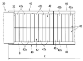
- the different type corrugated tube manufacturing apparatus 20 includes a supply unit 30, a plurality of pairs of molds 40, a drive mechanism unit 50, and an adhesion molding unit 70 (see FIG. 2 for the adhesion molding unit 70). ).
- the supply unit 30 is configured to extrude and supply the molten resin material 8 in a sheet form (see FIGS. 2 and 3).
- This supply part 30 is an extruder, extrudes the fuse
- the supply unit 30 supplies the sheet-like formed body (resin material 8) in a softened state.
- the softened state is harder than the molten state (hard to flow), and softened to a degree that allows molding before solidification.
- the sheet-like resin material 8 immediately after being supplied from the supply unit 30 is very likely to be deformed in the soft state in the softened state, which has just started to decrease in temperature from the molten state. Note that, in FIG. 4, the resin material 8 supplied in the form of a sheet is indicated by a two-dot chain line above the pair of molds 40.
- the T-die 32 is provided in such a posture that the resin material 8 is extruded in a sheet shape substantially parallel to the horizontal surface.
- the position of the tip of the T-die 32 may be referred to as the supply position of the supply unit 30.
- the sheet-like molded product (resin material 8) supplied by the supply unit 30 is larger than the distance between the end edges of one (outside) of the mold surfaces 42 of the molds 40 in the receiving posture pair described later.
- the width dimension is set (see FIGS. 3 and 4). That is, when the sheet-like formed body is deformed close to the mold surface 42 of the pair of molds 40 by gravity and when the sheet-like molded body is in close contact with the close contact formed portion 70, it is outside (at one end edge) It is dimensioning in consideration of preventing shortage. Thereby, as shown in the right side of FIG. 3 and FIG. 4, when the resin material 8 is in close contact with the mold surface 42, one end edge portion of the mold surface 42, that is, the mold surface It is possible to obtain a state in which the resin material 8 is in close contact with the entire structure 42.
- the said supply part 30 is comprised so that supply of the sheet-like molded object (resin material 8) is possible continuously. That is, the supply unit 30 continuously extrudes the molten resin material 8 into a sheet shape and supplies it.
- the pair of molds 40 is a mold for molding an irregular corrugated tube 10 having mold surfaces each having a portion corresponding to one side along the longitudinal direction of the irregular corrugated tube 10 in a sectional view.
- the longitudinal direction and the latitudinal direction may be used as the direction corresponding to the shape of the deformed corrugated tube 10.
- the mold surface 42 is a surface corresponding to the shape obtained by dividing the deformed corrugated tube 10 into two parts at both ends in the longitudinal direction of the sectional view.
- the mold surface 42 corresponds to one side along the longitudinal direction of the cross section view of the irregular corrugate tube 10, and at the end in the short direction, a substantially linear cross-sectional view along the longitudinal direction Have (see Figure 4).
- the mold surface 42 has a cross-sectional curved portion corresponding to a curved portion on both end sides in the cross-sectional view longitudinal direction of the modified corrugated tube 10 continuously on both sides of the substantially straight cross-sectional portion. . Then, when the paired molds 40 are butted in a posture in which the mold surfaces 42 face each other, the respective mold surfaces 42 form a surface corresponding to the shape of the different type corrugated tube 10.
- the mold surface 42 is a concave surface having a peak forming surface 42 a and a valley forming surface 42 b provided alternately and continuously in one direction (see FIGS. 3, 4 and 8).
- the peak forming surface 42 a is a concave surface which is recessed on the outer peripheral side
- the valley forming surface 42 b is a convex surface which is convex on the inner peripheral side.
- the ridge forming surface 42 a and the valley forming surface 42 b are substantially flush with each other at portions corresponding to both end portions in the cross sectional view of the modified corrugated tube 10 in the longitudinal direction (the ridge forming surface 42 a and the valley forming surface 42 b are It is formed in a straight line along the continuous direction).
- the height difference between the peak forming surface 42a and the valley forming surface 42b gradually decreases toward the end at both end portions in the longitudinal direction.
- the other end of the mold surface 42 is located longitudinally at each other end of the pair of molds 40 (see FIGS. 3 and 4). That is, when the pair of molds 40 are adjacent to each other in a posture in which the other ends are abutted, the other end of each mold surface 42 is adjacent.
- a plurality of the pair of molds 40 is prepared, and the shape is configured in the same manner.
- the pair of molds 40 is provided with a ridge forming surface 42a at one end and a valley forming surface 42b at the other end in one direction in which the ridge forming surface 42a and the valley forming surface 42b are arranged. It is provided. That is, when a plurality of pairs of molds 40 are arranged in one direction, the ridge portion forming surface 42 a and the valley portion forming surface 42 b are alternately arranged among the plurality of pairs of molds 40.
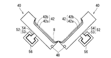
- the drive mechanism unit 50 can receive the sheet-like formed body (the resin material 8) supplied from the supply unit 30 by opening the mold surfaces 42 of the pair of molds 40 (here, upward).
- the posture can be changed between the receiving posture and the molding posture in which the mold surfaces 42 are closed (see FIGS. 2 and 4 to 7).
- the drive mechanism unit 50 changes the posture of the pair of molds 40 into the molding posture. It has become.
- the drive mechanism unit 50 moves the pairs of molds 40 in series on a pair of endless annular movement trajectories. Then, in a predetermined tube forming passage R in the moving track, the pair of molds 40 is set to the receiving posture at the upstream position of the tube forming passage R to which the sheet-like formed body is supplied from the supply unit 30
- the posture of the pair of molds 40 is gradually changed from the upstream toward the downstream of the tube forming path R so that the pair of molds 40 is in the forming posture at the downstream position of R (see FIG. 2).
- the tube forming path R extends along the supply direction at a position below the supply unit 30, and the upstream position thereof is located at the supply position of the supply unit 30 in plan view (see FIG. 3).
- the receiving posture of the pair of molds 40 is a posture in which the respective mold surfaces 42 face upward and the respective mold surfaces 42 are adjacent (may contact) at the other end edge. .
- the sheet-like molded body resin material 8
- the sheet-like molded body is attached to the mold surface 42 by its own weight.
- the receiving posture is set to a posture in which a substantially straight portion in sectional view of each of the mold surfaces 42 is positioned on a substantially horizontal surface (see FIG. 4).
- each mold surface 42 in a sectional view is substantially parallel to the horizontal plane, and the direction of gravity and the direction corresponding to the lateral direction of the irregular corrugated tube 10 substantially coincide with each other.
- the resin material 8 can contact the mold surface 42 with a smaller amount of deformation (see FIG. 4).
- the molding attitude of the pair of molds 40 is an attitude in which the resin material 8 supplied on the mold surface 42 is molded into the shape of the deformed corrugated tube 10 as a product.
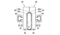
- the forming attitude is an attitude in which the mold faces 42 of the respective molds 40 of the pair are spaced apart from each other at one end edge and abutted at the other end edge to be adjacent (preferably, in contact) (See FIG. 6). That is, when the pair of molds 40 is in the above-described forming posture, it is possible to obtain the modified corrugated tube 10 in which the slit 16 opened at one end in the longitudinal direction of the sectional view is formed.
- the irregular corrugated tube 10 thus obtained has no cut marks as in the case of forming a slit by cutting.
- the forming attitude of the pair of molds 40 is not limited to this, and in the case of manufacturing a modified corrugated tube having no slit 16, an attitude in which both end edges of each mold surface 42 are adjacent to each other (See FIG. 7).
- the drive mechanism section 50 has a guided section 52, a pair of guide rails 56, and a feed section 62 (see FIGS. 2 and 4 to 7).
- the guided portion 52 is a member for moving the mold 40 along the guide rail 56, and is attached to each of the pairs of molds 40. More specifically, the guided portion 52 has a fitting portion 53 fitted to the guide rail 56 and a support portion 54 for supporting the mold 40 (see FIGS. 4 to 7).
- the support portion 54 is fixed at a base end portion thereof to a portion (here, approximately the center) opposite to the mold surface 42 with respect to the mold 40.
- the fitting portion 53 is formed to have a cross-sectional area larger than the support portion 54 continuously to the tip end side of the support portion 54. That is, the guided portion 52 is formed in a substantially T-shape as a whole.
- the pair of guide rails 56 is a member for guiding the plurality of pairs of molds 40 along the movement track in a state in which the guided portions 52 are fitted.
- the guide rail 56 is open at one end, and is formed in a substantially C shape in cross section having an internal space wider at the back of the opening 57 than the opening 57.
- Guided portions 52 attached to the respective dies 40 are fitted to the pair of guide rails 56 so that the dies 40 of the pair are supported one by one.
- a plurality of molds 40 are provided adjacent to each guide rail 56 so as to be arranged in an endless annular shape.
- one direction in which the ridge portion forming surface 42a and the valley portion forming surface 42b of the mold 40 are continuous to the guide rail 56 is substantially the same as the extending direction of the guide rail 56.
- the plurality of molds 40 may be moved as a whole by abutting on each other in the back and forth, and the molds 40 or the guided portions 52 are moved in a state of being connected by a coupling member not shown. It is also good.
- the pair of guide rails 56 is disposed along the moving track, and can twist the guided portion 52 so as to change the posture of the pair of molds 40 from the receiving posture to the forming posture on the tube forming path R. It is formed in shape. More specifically, the pair of molds 40 is placed in the receiving attitude (see FIG. 4) at the upstream position of the tube forming path R (the supply position of the supply unit 30), and the other end of the mold surface 42 is gradually increased. One edge is brought close while keeping the edges adjacent to each other, and the forming position (see FIG. 6) is obtained at the downstream position of the tube forming path R.
- the pair of guide rails 56 moves the pair of molds 40 apart from each other in the movement track other than the tube forming path R, and changes the posture of each mold 40 so as to be in the receiving posture at the upstream position of the tube forming path R It is configured to 4 to 6 show the postures of the pair of molds 40 at positions A to C in FIG. 2, respectively.
- the openings 57 face upward at the upstream position of the tube forming path R and are gradually inclined to face each other at the downstream position of the tube forming path R (here, slightly inclined upward) It is shaped so as to gradually turn upward as it approaches the upstream position of the tube forming path R again.
- the feed unit 62 is a mechanism for moving the plurality of molds 40 so as to move the feeding direction of the supply unit 30, that is, the direction from upstream to downstream of the tube forming passage R in the movement track.
- a pair of gears 64 which are rotationally driven in synchronization by the motor 63, are provided at predetermined positions on each movement track, and projections (not shown) capable of meshing with the respective gears 64 are provided.
- a configuration in which a plurality of dies 40 are fed can be adopted by meshing the respective gears 64 provided on the dies 40 and rotationally driven with the protrusions of the dies 40 (see FIG. 2). In FIG.
- a timing belt for synchronizing the pair of gear wheels 64 is indicated by a broken line. Moreover, it may replace with the said gearwheel, employ
- the feeding unit 62 is not limited to the above configuration, as long as it is possible to send a plurality of pairs of molds 40 in a predetermined direction of the movement trajectory, and various other configurations can be adopted.
- the postures of the plurality of pairs of molds 40 moved by the drive mechanism unit 50 are gradually changed in a state where the resin material 8 is provided on or between the mold surfaces 42 in the tube forming passage R.
- the plural pairs of molds 40 arranged in parallel can have different postures in the back and forth direction, so that the deviation of the mold surface 42 of the molds 40 in the front and back is reduced Is preferred.
- the drive mechanism unit 50 may set the twist of the pair of guide rails 56 (the opening 57) more gently so as to change the posture of the pair of molds 40 more gradually.
- the drive mechanism unit 50 is configured to move the pair of molds 40 while maintaining the receiving posture for a predetermined distance including the upstream position of the tube forming passage R (see FIGS. 2 and 3). ). That is, the pair of guide rails 56 is formed in a substantially linear (non-twisted) shape within a predetermined distance including the upstream position. This is a configuration for keeping the more easily deformable resin material 8 immediately after the supply without sticking and adhering the mold surface 42 more reliably.
- the drive mechanism unit 50 is configured to move the pair of molds 40 while maintaining the forming attitude for a predetermined distance including the downstream position of the tube forming path R (see FIG. 2). That is, the pair of guide rails 56 is formed in a substantially linear (non-twisted) shape within a predetermined distance including the downstream position. This is a configuration for bringing the resin material 8 molded in a softened state into a solidified state which is hardened so as to maintain its shape by itself.
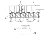
- the close contact molding unit 70 is configured to bring the resin material 8 supplied in the form of a sheet from the supply unit 30 into close contact with each mold surface 42 of the pair of molds 40 in the receiving posture (see FIG. 8). ).
- the contact molding unit 70 adopts a configuration using a vacuum molding method.
- the resin material 8 supplied onto the mold surface 42 of the pair of molds 40 is brought into close contact with the mold surface 42 by suction from the mold surface 42 side. It is a method of forming into a shape.
- the close contact molding portion 70 has a plurality of suction holes 72 formed in the pair of molds 40 and penetrates between the inner side of the mold surface 42 and the outer side of the mold 40. It is configured to draw in the air inside.
- a plurality of suction holes 72 are formed so as to be opened by the peak forming surface 42 a and the valley forming surface 42 b respectively.
- an airtight member 48 is provided to prevent air from leaking between the pair of molds 40 (the other end edges of the mold surface 42) when suction is performed by the close contact molding unit 70. (See Figures 4 to 7). More specifically, the airtight member 48 is formed of rubber or an elastically deformable resin material. The airtight member 48 is provided so as to project (in this case, slightly project) from each other end face of the pair of molds 40, and comes into contact with the receiving posture of the pair of molds 40 so as to be elastically deformed. Thus, air leakage from between the molds 40 can be suppressed between the mold surface 42 side of the pair of molds 40 and the opposite side thereof.
- the contact molding unit 70 is not limited to the configuration using the above-described vacuum molding method.
- a configuration may be employed in which compressed air is jetted from above to the mold surface 42 of the pair of molds 40 in the receiving position. That is, compressed air is jetted to the sheet-like resin material 8 supplied onto the pair of molds 40 in the receiving posture, and the resin material 8 is deformed so as to be pressed against the mold surface 42. Is in close contact with the mold surface 42.
- the resin material 8 is adhered to the mold surface 42 by bringing the female mold surface of the female mold corresponding to each mold 40 of the pair into close proximity to the mold 40 of the reception posture pair.
- the resin material 8 may be brought into close contact with the mold surface 42 sequentially by rotating the female mold having the female mold surface around the axis or rotating the female mold up and down. .
- the above-mentioned different type corrugated tube manufacturing apparatus 20 is not limited to the configuration in which the posture is changed while moving the pair of molds 40. That is, after the sheet-like molded body (the resin material 8) is supplied by the supply unit 30 onto the pair of molds 40 having a predetermined length in the receiving posture, the posture is changed to the molding posture without moving the pair of molds. It may be configured to
- the molten resin material 8 is extruded into a sheet and supplied (step (a), see the resin material 8 shown by the two-dot chain line on the upper side of FIG. 4). More specifically, the molten resin material 8 is extruded into a sheet form through the T-die 32 by the supply unit 30, and is supplied in a softened state in which the temperature is lower than that in the molten state.
- the sheet-like molded body (resin material 8) supplied is sagging on the mold surface 42 under the influence of gravity with respect to the pair of molds 40 in the receiving position located at the upstream position of the tube molding path R, It is placed in contact with the mold surface 42. Then, the sheet-like formed body is continuously supplied from the supply unit 30 and placed on the plurality of pairs of molds 40 moved from the upstream to the downstream of the tube forming path R.
- the sheet-like formed body supplied in the step (a) is formed into a shape in which the modified corrugated tube 10 is split open at one end in the longitudinal direction of the sectional view (step (b)). More specifically, air is sucked between the resin material 8 and the mold surface 42 through the suction holes 72 by the contact molding section 70 using a vacuum molding method, whereby the resin material 8 is transferred to the mold surface 42. Close contact (see FIGS. 4 and 8). The sheet-like resin material 8 is deformed so as to be close to the mold surface 42 also by the influence of gravity.
- molded at the process (b) is closed (process (c)). That is, when the pair of molds 40 is gradually changed to the forming posture as it is moved from the upstream to the downstream of the tube forming passage R, the resin material 8 is attached to one end of the corrugated tube 10 in the cross sectional view in the longitudinal direction. The corresponding parts are deformed so as to gradually approach each other (see FIG. 5). Even in this state, the resin material 8 is kept in the softened state while the temperature is gradually lowered. Here, the temperature of the resin material 8 is lowered by touching the mold 40 and air.
- the resin material 8 becomes a shape of a modified corrugated tube 10 as a product (see FIG. 6).
- the resin material 8 is in a solidified state hardened to such an extent that the shape can be maintained independently.
- the mold surface 42 of the pair of molds 40 is separated from the outer peripheral portion of the deformed corrugated tube 10 (see FIG. 2). Then, the completed irregular corrugated tube 10 is sent out to the downstream side from the tube forming passage R.
- the irregular corrugated tube 10 is manufactured.
- the pair of molds 40 is at one end of the mold surface 42 while the temperature is maintained in a softened state so high that the resin materials 8 stick to one another.
- the edge may be configured to be changed to an adjacent forming position (see FIG. 7). That is, the structure which provided the mechanism which heats the metal mold
- the resin material 8 melted by the feeding unit 30 is extruded into a sheet and supplied, and the sheet-like molded body supplied from the feeding unit 30 (resin material After 8) is received in the receiving position, the pair of molds 40 is configured to be changed into the forming position. That is, the resin material 8 which is likely to be deformed immediately after being supplied with a temperature decrease from the molten state immediately after the supply is supplied in a sheet-like shape in which the resin materials 8 do not easily stick to each other.
- the sheet-like molded body to be supplied is received by the pair of molds 40 in a receiving posture in which the resin materials 8 are not easily attached to each other. Then, after being received in the receiving posture and having a temperature lower than that immediately after the supply, the pair of molds 40 is changed into the forming posture, and formed into the shape of the modified corrugated tube. For this reason, it is possible to prevent the resin material 8 immediately after being supplied from being bent and crushed under the influence of gravity or to prevent the resin materials 8 from sticking to each other, and to manufacture the flat irregular corrugated tube 10 having a large long / short ratio.
- the molding attitude of the pair of molds 40 is such that each mold surface 42 has a predetermined interval at one end edge.
- the receiving attitude of the pair of molds 40 is such that each mold surface 42 faces upward.
- the sheet-like formed body (resin material 8) supplied from the supply unit 30 onto the mold 40 in the receiving posture is deformed so as to be close to the mold surface 42 under the influence of gravity, and the mold It can be prevented from being bent away from the surface 42 and collapsing or sticking to each other.
- the flat irregular corrugated tube 10 having a large ratio of length to size can be manufactured more reliably.
- the sheet-like formed body is continuously supplied by the supply unit 30, and the pair of molds 40 is moved in a plurality on each of a pair of movement trajectories so as to be in the receiving attitude at the upstream position of the tube forming path R.
- the molding position is set at the downstream position.
- the sheet-like resin material 8 supplied from the supply unit 30 is continuously received by the plurality of pairs of molds 40, and the postures of the respective pairs of molds 40 are sequentially changed to the forming posture to form the different type corrugated tube 10 Can be manufactured. That is, the irregular corrugated tube 10 having a high ratio of length to length can be manufactured continuously.
- the pair of molds 40 can be moved while changing the posture between the receiving posture and the molding posture. As described above, the pair of molds 40 can be moved while changing the posture with a simple configuration.
- the existing corrugated tube manufacturing apparatus is an apparatus adopting a configuration using a vacuum forming method such as the above-mentioned close contact molding portion 70 in place of the blow molding method in the corrugated tube manufacturing device disclosed in Patent Document 1. is there. That is, a molten resin material is extruded into a cylindrical shape by an extruder and supplied into a pair of closed molds forming a cylindrical molding space, and air is sucked from the mold surface side to form a cylindrical mold. The body is in close contact with the mold surface.
- a corrugated tube of atypical type with a long / short ratio of up to 2.5 times could be formed in the same way as a corrugated tube with a cylindrical shape (1 ⁇ long / short ratio), but the long / short ratio is It has not been possible to produce more than two different corrugated tubes 10. This is because the molded body supplied from the extruder is very easy to be deformed in the soft state which has just begun to drop in temperature from the molten state, and the portions along the longitudinal direction of the sectional view are positioned at narrow intervals in the lateral direction. It is believed that this is because the portions of the molded body immediately after being supplied along the longitudinal direction stick to each other. That is, in such a case, the resin material can not be molded into the shape of the corrugated tube without being in intimate contact with the mold surface.
- the molded product (resin material 8) supplied from the supply unit 30 is supplied in the form of a sheet, although it is in a soft state shortly after the temperature begins to drop from the molten state.
- the pair of molds 40 is formed by being reposted to the forming position. That is, in the soft state immediately after the supply, the resin material 8 is in a state in which there is no opposing portion at a narrow interval, and then the temperature is further lowered to be harder than immediately after the supply (the resin material 8 has a moldable degree of softness) Is molded into the shape of a modified corrugated tube 10.
- the receiving attitude of the pair of molds 40 is also such that the sheet-like formed body to be supplied is deformed so as to be close to the mold surface 42 by the influence of gravity. Therefore, it is possible to prevent the resin material 8 from being deformed in a softer state immediately after the supply. Thereby, the resin material 8 can be firmly adhered to the mold surface 42 by the adhesion molding portion 70, and can be molded into the shape of the modified corrugated tube 10.
- the problems of the existing corrugated tube manufacturing apparatus can be solved, and the flat type having a length ratio of 3 or more which is difficult to manufacture by the existing corrugated tube manufacturing apparatus It is considered that even the irregular corrugated tube 10 can be manufactured.
Landscapes
- Engineering & Computer Science (AREA)
- Mechanical Engineering (AREA)
- Manufacturing & Machinery (AREA)
- General Engineering & Computer Science (AREA)
- Extrusion Moulding Of Plastics Or The Like (AREA)
- Details Of Indoor Wiring (AREA)
Abstract
Description
まず、異型コルゲートチューブ10について説明する(図1参照)。この異型コルゲートチューブ10は、自動車等に設けられるワイヤーハーネス(WH)を保護する外装材等として用いられる筒状部材である。以下、異型コルゲートチューブ10が、ワイヤーハーネス(WH)を保護する外装材である例で説明する。
次に、上述した扁平な異型コルゲートチューブ10を製造するための異型コルゲートチューブ製造装置20について説明する。異型コルゲートチューブ製造装置20は、供給部30と、複数の対の金型40と、駆動機構部50と、密着成形部70とを備えている(図2、密着成形部70については図8参照)。
次に、異型コルゲートチューブ10の製造方法について、上記異型コルゲートチューブ製造装置20を用いた例で説明する。なお、複数の対の金型40は駆動機構部50により移動軌道に沿って移動されているものとする。
以下、既存のコルゲートチューブ製造装置及び本発明に係る異型コルゲートチューブ製造装置20による、長短比の異なる扁平な異型コルゲートチューブ10の製造可否について説明する。
12 山部
14 谷部
16 スリット
20 異型コルゲートチューブ製造装置
30 供給部
40 金型
42 金型面
50 駆動機構部
70 密着成形部
WH ワイヤーハーネス
Claims (7)
- 扁平な異型コルゲートチューブを製造する異型コルゲートチューブ製造装置であって、
溶融樹脂をシート状に押出して供給する供給部と、
前記異型コルゲートチューブの断面視長手方向に沿った一側部に対応する部分を有する金型面をそれぞれ有する異型コルゲートチューブ成形用の対の金型と、
前記対の金型を、前記金型面同士が開いて前記供給部から供給されるシート状の成形体を受取可能な受取姿勢と、前記金型面同士が閉じた成形姿勢とで姿勢変更可能で、前記供給部から供給される前記シート状の成形体が前記受取姿勢の前記対の金型で受け取られてから、前記対の金型を前記成形姿勢に姿勢変更させる駆動機構部と、
前記供給部から供給される前記シート状の成形体を、前記受取姿勢の前記対の金型の前記金型面に対して密着させる密着成形部と、
を備える異型コルゲートチューブ製造装置。 - 請求項1に記載の異型コルゲートチューブ製造装置であって、
前記対の金型の成形姿勢は、それぞれの前記金型面が一方の端縁部で所定の間隔をあけると共に他方の端縁部で隣接する姿勢である、異型コルゲートチューブ製造装置。 - 請求項1に記載の異型コルゲートチューブ製造装置であって、
前記対の金型の受取姿勢は、それぞれの前記金型面が上方に臨むと共に他方の端縁部で隣接する姿勢である、異型コルゲートチューブの製造装置。 - 請求項1に記載の異型コルゲートチューブ製造装置であって、
前記供給部は、前記シート状の成形体を連続的に供給可能で、
前記駆動機構部は、複数の前記対の金型を、それぞれ一対の無端環状の移動軌道上で直列に移動させ、前記移動軌道中の所定のチューブ成形路において、前記供給部から前記シート状の成形体が供給される前記チューブ成形路の上流位置で前記対の金型を受取姿勢にすると共に前記チューブ成形路の下流位置で前記対の金型を成形姿勢にするように、上流から下流に向けて前記対の金型を徐々に姿勢変更させる、異型コルゲートチューブ製造装置。 - 請求項1に記載の異型コルゲートチューブ製造装置であって、
前記駆動機構部は、
複数の前記対の金型それぞれに取り付けられている被案内部と、
前記移動軌道に沿って配設され、前記対の金型を前記チューブ成形路上で受取姿勢から成形姿勢に姿勢変更させるように前記被案内部を案内可能な形状に形成されている一対の案内レールと、
複数の前記対の金型を、それぞれ、前記チューブ成形路の上流から下流に向けて移動するように送る送り部と、
を有している異型コルゲートチューブ製造装置。 - 扁平な異型コルゲートチューブを製造する異型コルゲートチューブ製造方法であって、
(a)溶融樹脂をシート状に押出して供給する工程と、
(b)前記工程(a)で供給されたシート状の成形体を、前記異型コルゲートチューブを断面視長手方向の一端部で割り開いた形状に成形する工程と、
(c)前記工程(b)で成形された前記異型コルゲートチューブを割り開いた形状の成形体を閉じる工程と、
を備える異型コルゲートチューブ製造方法。 - 扁平な異型コルゲートチューブであって、
断面視長手方向の寸法が短手方向の寸法に対して3倍以上の寸法に設定されている異型コルゲートチューブ。
Priority Applications (2)
| Application Number | Priority Date | Filing Date | Title |
|---|---|---|---|
| US13/809,168 US20130118631A1 (en) | 2010-07-26 | 2011-02-25 | Device for manufacturing profile corrugated tube, method for manufacturing profile corrugated tube and profile corrugated tube |
| CN201180036611.6A CN103038050B (zh) | 2010-07-26 | 2011-02-25 | 用于制造异型波纹管的装置、用于制造异型波纹管的方法和异型波纹管 |
Applications Claiming Priority (2)
| Application Number | Priority Date | Filing Date | Title |
|---|---|---|---|
| JP2010167007A JP5565168B2 (ja) | 2010-07-26 | 2010-07-26 | 異型コルゲートチューブ製造装置及び異型コルゲートチューブ製造方法 |
| JP2010-167007 | 2010-07-26 |
Publications (1)
| Publication Number | Publication Date |
|---|---|
| WO2012014513A1 true WO2012014513A1 (ja) | 2012-02-02 |
Family
ID=45529737
Family Applications (1)
| Application Number | Title | Priority Date | Filing Date |
|---|---|---|---|
| PCT/JP2011/054344 Ceased WO2012014513A1 (ja) | 2010-07-26 | 2011-02-25 | 異型コルゲートチューブ製造装置、異型コルゲートチューブ製造方法及び異型コルゲートチューブ |
Country Status (4)
| Country | Link |
|---|---|
| US (1) | US20130118631A1 (ja) |
| JP (1) | JP5565168B2 (ja) |
| CN (1) | CN103038050B (ja) |
| WO (1) | WO2012014513A1 (ja) |
Families Citing this family (5)
| Publication number | Priority date | Publication date | Assignee | Title |
|---|---|---|---|---|
| EP3110619B1 (en) * | 2014-02-25 | 2019-04-10 | Sns Unicorp Pty. Ltd. | Method and apparatus for forming profiled articles |
| USD787649S1 (en) * | 2016-01-28 | 2017-05-23 | Prinsco, Inc. | Webless corrugated dual wall foundation drain |
| US10428978B2 (en) | 2016-01-29 | 2019-10-01 | Prinsco, Inc. | Webless corrugated dual wall foundation drain and related method |
| CN110014628A (zh) * | 2017-12-23 | 2019-07-16 | 中航森瑞武汉新材料有限公司 | 一种用于制备pe、ppr波纹管的冷却水次序却定型装置 |
| JP7687111B2 (ja) * | 2021-07-26 | 2025-06-03 | トヨタ自動車株式会社 | 管体の製造装置 |
Citations (5)
| Publication number | Priority date | Publication date | Assignee | Title |
|---|---|---|---|---|
| JPH01237349A (ja) * | 1988-03-15 | 1989-09-21 | Mitsubishi Motors Corp | 吸気管の製造方法 |
| JPH10217319A (ja) * | 1997-01-31 | 1998-08-18 | U C Sangyo Kk | 合成樹脂製コルゲート管及びその製造方法と装置 |
| JP2000343592A (ja) * | 1999-06-08 | 2000-12-12 | Sumitomo Wiring Syst Ltd | 管体の製造装置 |
| JP2007181268A (ja) * | 2005-12-27 | 2007-07-12 | Yazaki Corp | スライド構造体用の給電装置 |
| JP2010083398A (ja) * | 2008-10-01 | 2010-04-15 | Furukawa Electric Co Ltd:The | スライドドア用給電装置 |
Family Cites Families (5)
| Publication number | Priority date | Publication date | Assignee | Title |
|---|---|---|---|---|
| DE3027045A1 (de) * | 1980-07-17 | 1982-02-11 | Hegler, Wilhelm, 8730 Bad Kissingen | Flach-hohlkoerper, insbesondere lueftungs- und drainage- bzw. absorber-platte |
| CN1055682A (zh) * | 1990-04-14 | 1991-10-30 | 丁方儒 | 一种扁形波纹管的生产方法 |
| DE4204041C2 (de) * | 1992-02-12 | 1994-03-03 | 2 H Kunststoff Gmbh | Verfahren zur Herstellung eines Einbauelements für Wärmetauscher-, Stoffaustauscher- und/oder Bioreaktor-Systeme und Vorrichtung zur Durchführung des Verfahrens |
| US6193496B1 (en) * | 1999-03-01 | 2001-02-27 | Cullom Machine Tool & Die, Inc. | Molding machine with mold block carriage |
| DE102006005736A1 (de) * | 2006-02-07 | 2007-08-09 | Thyssenkrupp Presta Ag | Wellrohr |
-
2010
- 2010-07-26 JP JP2010167007A patent/JP5565168B2/ja not_active Expired - Fee Related
-
2011
- 2011-02-25 US US13/809,168 patent/US20130118631A1/en not_active Abandoned
- 2011-02-25 CN CN201180036611.6A patent/CN103038050B/zh not_active Expired - Fee Related
- 2011-02-25 WO PCT/JP2011/054344 patent/WO2012014513A1/ja not_active Ceased
Patent Citations (5)
| Publication number | Priority date | Publication date | Assignee | Title |
|---|---|---|---|---|
| JPH01237349A (ja) * | 1988-03-15 | 1989-09-21 | Mitsubishi Motors Corp | 吸気管の製造方法 |
| JPH10217319A (ja) * | 1997-01-31 | 1998-08-18 | U C Sangyo Kk | 合成樹脂製コルゲート管及びその製造方法と装置 |
| JP2000343592A (ja) * | 1999-06-08 | 2000-12-12 | Sumitomo Wiring Syst Ltd | 管体の製造装置 |
| JP2007181268A (ja) * | 2005-12-27 | 2007-07-12 | Yazaki Corp | スライド構造体用の給電装置 |
| JP2010083398A (ja) * | 2008-10-01 | 2010-04-15 | Furukawa Electric Co Ltd:The | スライドドア用給電装置 |
Also Published As
| Publication number | Publication date |
|---|---|
| CN103038050A (zh) | 2013-04-10 |
| JP2012025073A (ja) | 2012-02-09 |
| US20130118631A1 (en) | 2013-05-16 |
| CN103038050B (zh) | 2015-05-20 |
| JP5565168B2 (ja) | 2014-08-06 |
Similar Documents
| Publication | Publication Date | Title |
|---|---|---|
| WO2012014513A1 (ja) | 異型コルゲートチューブ製造装置、異型コルゲートチューブ製造方法及び異型コルゲートチューブ | |
| US9625066B2 (en) | Helically wound plastic tubing with variable profile thickness and methods of making the same | |
| CA2802079C (en) | Method for producing a plastics article and blow mold for carrying out the method | |
| WO2015048155A1 (en) | Improved filament for fused deposit modeling | |
| JP5379051B2 (ja) | 帯状ゴムの製造方法 | |
| USRE29331E (en) | Method and structure for reclosable containers | |
| JP6990758B2 (ja) | コルゲータ、押出システムおよび方法 | |
| US9815236B2 (en) | Method for manufacturing tubes and tube likely to be obtained by such a method | |
| US7517210B1 (en) | Apparatus for the manufacture of compound pipes | |
| JP5403252B2 (ja) | 成形方法 | |
| US3246672A (en) | Method and structure for reclosable containers | |
| JP2014073588A (ja) | ゴムストリップの貼付装置及び貼付方法 | |
| US8578996B2 (en) | Method and apparatus for producing single yarn-adhered sheet | |
| JP2005059240A (ja) | 合成樹脂供給装置 | |
| JP2016127615A (ja) | 螺旋型コルゲートチューブ及び螺旋型コルゲートチューブ付電線 | |
| CN104723534A (zh) | 塑料容器用连续成型设备 | |
| JP2014180780A (ja) | 搬送装置 | |
| JP2012025006A (ja) | コルゲートチューブ製造方法及びコルゲートチューブ | |
| JP2013010263A (ja) | ダクトの成形方法及びダクト | |
| JP2631887B2 (ja) | 外面に中実の横リブを有するプラスチック管の成形装置、このような装置を備えた設備およびプラスチック管を成形する方法 | |
| JP2012252977A (ja) | ワイヤハーネス製造システム | |
| US20040175537A1 (en) | Polymer component, apparatus and method | |
| JP2005161765A (ja) | 製管用帯状部材 | |
| JP6131093B2 (ja) | 異径チューブの引取装置及び引取方法 | |
| WO2011152107A1 (ja) | ビード部材の製造装置及び製造方法 |
Legal Events
| Date | Code | Title | Description |
|---|---|---|---|
| WWE | Wipo information: entry into national phase |
Ref document number: 201180036611.6 Country of ref document: CN |
|
| 121 | Ep: the epo has been informed by wipo that ep was designated in this application |
Ref document number: 11812109 Country of ref document: EP Kind code of ref document: A1 |
|
| WWE | Wipo information: entry into national phase |
Ref document number: 13809168 Country of ref document: US |
|
| NENP | Non-entry into the national phase |
Ref country code: DE |
|
| 122 | Ep: pct application non-entry in european phase |
Ref document number: 11812109 Country of ref document: EP Kind code of ref document: A1 |