WO2012014342A1 - 呼び出し方法、コアネットワーク装置、無線アクセスネットワーク装置及びゲートウェイ装置 - Google Patents
呼び出し方法、コアネットワーク装置、無線アクセスネットワーク装置及びゲートウェイ装置 Download PDFInfo
- Publication number
- WO2012014342A1 WO2012014342A1 PCT/JP2010/073775 JP2010073775W WO2012014342A1 WO 2012014342 A1 WO2012014342 A1 WO 2012014342A1 JP 2010073775 W JP2010073775 W JP 2010073775W WO 2012014342 A1 WO2012014342 A1 WO 2012014342A1
- Authority
- WO
- WIPO (PCT)
- Prior art keywords
- call
- information
- network device
- core network
- user terminal
- Prior art date
Links
Images


Classifications
-
- H—ELECTRICITY
- H04—ELECTRIC COMMUNICATION TECHNIQUE
- H04W—WIRELESS COMMUNICATION NETWORKS
- H04W68/00—User notification, e.g. alerting and paging, for incoming communication, change of service or the like
- H04W68/005—Transmission of information for alerting of incoming communication
-
- H—ELECTRICITY
- H04—ELECTRIC COMMUNICATION TECHNIQUE
- H04W—WIRELESS COMMUNICATION NETWORKS
- H04W28/00—Network traffic management; Network resource management
- H04W28/02—Traffic management, e.g. flow control or congestion control
- H04W28/0252—Traffic management, e.g. flow control or congestion control per individual bearer or channel
- H04W28/0263—Traffic management, e.g. flow control or congestion control per individual bearer or channel involving mapping traffic to individual bearers or channels, e.g. traffic flow template [TFT]
-
- H—ELECTRICITY
- H04—ELECTRIC COMMUNICATION TECHNIQUE
- H04W—WIRELESS COMMUNICATION NETWORKS
- H04W68/00—User notification, e.g. alerting and paging, for incoming communication, change of service or the like
- H04W68/02—Arrangements for increasing efficiency of notification or paging channel
-
- H—ELECTRICITY
- H04—ELECTRIC COMMUNICATION TECHNIQUE
- H04W—WIRELESS COMMUNICATION NETWORKS
- H04W92/00—Interfaces specially adapted for wireless communication networks
- H04W92/16—Interfaces between hierarchically similar devices
- H04W92/24—Interfaces between hierarchically similar devices between backbone network devices
-
- H—ELECTRICITY
- H04—ELECTRIC COMMUNICATION TECHNIQUE
- H04W—WIRELESS COMMUNICATION NETWORKS
- H04W8/00—Network data management
- H04W8/30—Network data restoration; Network data reliability; Network data fault tolerance
Definitions
- the present invention relates to a calling method, a core network device, a radio access network device, and a gateway device for calling a user terminal when a packet addressed to an idle user terminal is received.
- a core network device for example, MME (Mobility Management Entity) or SGSN (Serving GPRS Support Node) provided in the core network
- MME Mobility Management Entity
- SGSN Serving GPRS Support Node
- a radio access network apparatus for example, RNC (Radio Network Controller) / BSC (Base Station Controller) or eNodeB
- the radio access network device transmits a paging signal for calling the user terminal in response to the paging signal received from the core network device.
- the user terminal performs an incoming call process with the core network device according to the paging signal transmitted from the radio access network device (for example, Non-Patent Document 1).
- the core network device or the radio access network device performs call restriction that restricts the call of the user terminal. ing.
- call restriction is performed, for example, when the core network device or the radio access network device is in a congested state.
- the present invention has been made in view of such a point, and when there is an incoming packet to an idle user terminal, a calling method capable of flexibly calling the user terminal, a core network device, An object is to provide a radio access network device and a gateway device.
- the calling method is a calling method for calling a user terminal when a packet for an idle user terminal is received by the first gateway device, wherein the second gateway device is: Setting the incoming call type information of the packet received by the first gateway device to a call request signal, and transmitting the call request signal to the core network device; and the core network device from the second gateway device. And determining whether or not to call the user terminal based on the incoming call type information included in the call request signal.
- the second gateway device sets the incoming call type information for the packet for the idle user terminal received by the first gateway device in the call request signal. Based on the incoming call type information included, it can be determined whether or not the user terminal should be called. Therefore, the core network device can call the user terminal depending on the contents of the incoming call type information even in a situation where the call restriction of the normal user terminal is performed such as when the own device is in a congested state.
- the calling method is a calling method for calling a user terminal when a packet for an idle user terminal is received by the first gateway device, wherein the second gateway device is Setting the incoming call type information of the packet received by the first gateway device to a call request signal, and transmitting the call request signal to the core network device; and the core network device from the second gateway device. Setting call information for calling the user terminal as a call signal based on the incoming call type information included in the call request signal, and transmitting the call signal to a radio access network device; and the radio access network device Is called from the core network device Based on the call information included in the signal, characterized by and a step of determining whether or not to call the user terminal.
- the radio access network device since the core network device sets the call information as the call signal based on the incoming call type information included in the call request signal from the second gateway device, the radio access network device is included in the call signal.
- the user terminal can be called based on the call information. Therefore, the radio access network device can call the user terminal depending on the content of the call information even in a situation where call regulation of the normal user terminal is normally performed, for example, when the own device is in a congested state.
- a core network device is a core network device that calls a user terminal when a packet for an idle user terminal is received by the first gateway device, the first gateway device comprising: Receiving a call request signal including incoming call type information indicating an incoming call type of the packet from a second gateway device connected to the apparatus, and based on the incoming call type information included in the received call request signal, the user terminal It is characterized by determining whether to call.
- a radio access network apparatus is a radio access network apparatus that calls a user terminal when a packet for an idle user terminal is received by a first gateway apparatus, the core network
- a device receives a call request signal including incoming call type information indicating the incoming call type of the packet from a second gateway device connected to the first gateway device
- the incoming call type information is sent from the core network device to the incoming call type information.
- a gateway device is a gateway device that transmits a call request signal to a core network device when a packet for an idle user terminal is received, the incoming call type information of the packet Is set as the call request signal, and the call request signal is transmitted to the core network device.
- a calling method a core network device, a radio access network device, and a gateway device capable of flexibly calling a user terminal when a packet arrives at an idle user terminal. can do.
- 1 is a schematic configuration diagram of a mobile communication system according to a first embodiment. It is a function block diagram of the call process in the mobile communication system which concerns on 1st Embodiment. It is a sequence diagram which shows the calling operation
- FIG. 1 is a schematic configuration diagram of a mobile communication system according to the first embodiment.
- the mobile communication system according to the first embodiment is a system having compatibility between the next generation communication system such as LTE and the second / third generation communication system.
- EPC Evolved Packet Core 1 which is the core network of the next generation
- E-UTRAN2 which is the radio access network of the next generation communication method
- UMTS Universal Mobile Telecommunications System
- a GPRS (General Packet Radio Service) core network 3 and a UTRAN / GERAN 4 which is a radio access network of the second / third generation communication system are configured.
- the UE (User Equipment) 10 is a user terminal corresponding to one or a plurality of communication methods such as a mobile phone terminal and a notebook personal computer.
- the UE 10 corresponds to the next generation communication method such as LTE and the second / third generation communication method, and can be located in both the E-UTRAN2 and UTRAN / GERAN4 wireless zones.
- the UE 10 may be configured to support only a next-generation communication scheme such as LTE, and can be located only in the radio zone of the E-UTRAN2.
- EPC1 moves between the wireless zones of P-GW (PDN Gateway) 20 (first gateway device), which is a connection point with PDN (Packet Data Network) such as the Internet, and E-UTRAN2 and UTRAN / GERAN4
- PDN Packet Data Network
- An S-GW (Serving Gateway) 30 (second gateway device) that is an anchor point of the packet transmission path of the UE 10 and an MME 40 (core network device) that calls the UE 10 located in the radio zone of the E-UTRAN 2 Provided.
- the S-GW 30 is connected to the P-GW 20, the MME 40, an eNodeB 50 and an SGSN 60 described later.
- the E-UTRAN 2 is provided with an eNodeB 50 (radio access network device) that performs radio communication with the UE 10 located in the radio zone of the E-UTRAN 2.
- the eNodeB 50 is connected to the S-GW 30 and the MME 40.
- the UMTS / GPRS core network 3 is provided with an SGSN 60 (core network device) that calls the UE 10 located in the UTRAN / GERAN 4 radio zone.
- SGSN 60 core network device
- the UTRAN / GERAN 4 includes a Node B (not shown) that performs radio communication with the UE 10 located in the radio zone of the E-UTRAN 2 and an RNC / BSC 70 (wireless) that controls radio communication between the UE 10 and the Node B (not shown).
- An access network device is provided.
- the RNC / BSC 70 is connected to the SGSN 60.
- a PDN connection that is an IP session is set between the UE 10 and the PDN (not shown) via the P-GW 20.
- the UE 10 identified by the IP address is connected to a PDN (not shown) identified by an APN (Access Point Name).
- APN Access Point Name
- an EPS bearer which is a logical communication path of the next generation communication method, between the UE 10 located in the radio zone of the E-UTRAN 2 and the P-GW 20 or the S-GW 30.
- a packet received from a PDN (not shown) is transmitted to the UE 10 located in the radio zone of the E-UTRAN 2 via the EPS bearer.
- a packet received from a PDN (not shown) is discriminated in accordance with a TFT (Traffic Flow Template) in the P-GW 20 or S-GW 30 and mapped to an EPS bearer for each flow of the packet. It is transmitted via the EPS bearer.
- TFT Traffic Flow Template
- a UMTS / GPRS bearer which is a logical communication path of the second / third generation communication method, is provided between the UE 10 and the SGSN 60 located in the UTRAN / GERAN4 radio zone. Is set.
- Such a UMTS / GPRS bearer is connected to an EPS bearer set between the SGSN 60 and the S-GW 30 or the P-GW 20.
- a packet received from a PDN (not shown) is transmitted to the UE 10 located in the UTRAN / GERAN4 radio zone via the UMTS / GPRS bearer and the EPS bearer.
- a default bearer is set between the UE 10 and the P-GW 20 located in the E-UTRAN2 or UTRAN / GERAN4 radio zone when the above PDN connection is set.
- FIG. 2 is a functional configuration diagram of call processing in the mobile communication system according to the first embodiment.
- ISR Interle State Reduction
- ISR is applied to reduce the frequency with which the UE 10 in an idle state moving between the radio zones of E-UTRAN 2 and UTRAN / GERAN 4 updates the location registration area.
- the P-GW 20 receives packets belonging to different communication bearers (in this case, information A and information B) for the UE 10 in an idle state from a PDN (not shown).
- the P-GW 20 encapsulates a packet for each communication bearer, and transmits the packet to the S-GW 30 as a GTP-U packet or a GRE (Generic-Routing-Encapsulation) packet.
- GTP-U packet or a GRE (Generic-Routing-Encapsulation) packet.
- GRE Generic-Routing-Encapsulation
- the S-GW 30 sets the incoming call type information indicating the incoming type of a packet for the idle UE 10 received by the P-GW 20 in “Downlink Data Notification”.
- Downlink Data Notification is a call request signal for requesting a call of UE 10 in an idle state.
- the S-GW 30 is at least one of bearer identification information, bearer QoS information, default bearer information, P-GW information, PDN connection information, flow identification information, and S-GW load information.
- the incoming call type information is set based on
- the bearer identification information is identification information of a bearer that transmits a packet received by the P-GW 20.
- the bearer identification information includes, for example, “EPS bearer ID” for identifying the above-described EPS bearer, “GPRS / UMTS bearer ID” for identifying the above-described GPRS / UMTS bearer, and the like.
- the bearer QoS information is information indicating the QoS of the bearer for transmitting a packet received by the P-GW 20.
- the bearer QoS information includes, for example, “ARP: Allocation and Retention Priority” indicating the relative priority between the EPS bearers when the above-described EPS bearer is set / changed, and the above-described EPS bearer and UMTS / GPRS bearer.
- GBR Guaranted Bit Rate
- MBR Maximum Bit Rate
- QCI QoS Class Identifier
- the default bearer information is information on a default bearer set between the UE 10 and the P-GW 20 as described above.
- the default bearer information includes, for example, “default bearer ID” for identifying the default bearer, information indicating the QoS of the default bearer, and the like.
- the P-GW information (first gateway device information) is information on the P-GW 20 that has received a packet for the UE 10 in an idle state from a PDN (not shown).
- the P-GW information includes, for example, a P-GW identifier that identifies the P-GW 20, a termination identifier of a GTP tunnel that terminates at the P-GW 20, “TEID: Tunnel Endpoint Identifier”, and a GPE tunnel termination identifier “ GRE Key ”, IP address of P-GW20, etc.
- the PDN connection information is information on the above-described PDN connection set between the UE 10 and the PDN (not shown) via the P-GW 20 in order to transmit a packet received by the P-GW 20.
- the PDN connection information includes, for example, “APN: Access Point Name” that identifies both the above-mentioned PDN (not shown) and the P-GW 20 that is a connection point to the PDN (not shown).
- the flow identification information is identification information of the service data flow of the IP packet received by the P-GW 20.
- the flow identification information includes, for example, “TFT: Traffic Flow Template”.
- the S-GW load information (second gateway device load information) is information indicating the load of the S-GW 30.
- the incoming call type information includes at least the bearer identification information, bearer QoS information, default bearer information, P-GW information, PDN connection information, flow identification information, and S-GW load information as described above. One may be included as it is.
- the incoming call type information includes at least one of the above bearer identification information, bearer QoS information, default bearer information, P-GW information, PDN connection information, flow identification information, and S-GW load information. It may be a parameter associated with one (for example, 1: incoming call type 1, 2: incoming call type 2, 3: incoming call type 3, etc.).
- the S-GW 30 transmits “Downlink Data Notification” including incoming call type information to the core network device connected to the S-GW 30. Specifically, the S-GW 30 transmits “Downlink Data Notification” including incoming call type information to the MME 40 that is a core network device provided in the EPC 1 and the SGSN 60 that is a core network device provided in the UMTS / GPRS core network 3. ".
- the MME 40 which is a core network device provided in the EPC1, calls the UE 10 located in the radio zone of the E-UTRAN2 based on the incoming call type information included in the "Downlink Data Notification" from the S-GW 30 Judging.
- the MME 40 transmits “Paging” to the eNodeB 50 that is a radio access network device provided in the E-UTRAN 2 when the incoming call type information is predetermined.
- “Paging” is a call signal for calling the UE 10.
- the eNodeB 50 transmits “Paging” to the UE 10 in response to “Paging” from the MME 40.
- the SGSN 60 which is a core network device provided in the UMTS / GPRS core network 3 is located in the UTRAN / GERAN4 wireless zone based on the incoming call type information included in the “Downlink Data Notification” from the S-GW 30. It is determined whether or not to call UE10. If it is predetermined incoming call type information, the SGSN 60 transmits “Paging” to the RNC / BSC 70 which is a radio access network device provided in the UTRAN / GERAN 4. The RNC / BSC 70 transmits “Paging” to the UE 10 in response to “Paging” from the SGSN 60.
- the S-GW 30 sets the incoming call type information for the idle UE 10 received by the P-GW 20 to “Donlink Data Notification”.
- Each of the network devices MME 40 and SGSN 60 can determine whether or not to call UE 10 based on the incoming call type information included in “Donlink Data Notification”. Therefore, the MME 40 and the SGSN 60 can call the UE 10 depending on the contents of the incoming call type information even in a situation where the call restriction of the UE 10 is normally performed, for example, when the own device is in a congestion state.
- bearer identification information bearer identification information
- bearer QoS information default bearer information
- P-GW information PDN connection information
- flow identification information PDN connection information
- S-GW load information Since the incoming call type information is set based on at least one of the following, in the MME 40 and the SGSN 60 that are core network devices, for each bearer, for each bearer QoS, for each PDN connection, for each flow, or a combination thereof, etc. Whether or not to call the UE 10 can be determined under detailed conditions, and flexible call control can be performed.
- the S-GW 30 transmits “Downlink Data Notification” including the incoming call type information to both the MME 40 and the SGSN 60, and the MME 40 and the SGSN 60 respectively receive the incoming call type information.
- the example which determines whether to call UE10 based on was demonstrated.
- the present invention is not limited to such an example, and “Donlink Data Notification” including incoming call type information is transmitted to either the MME 40 or the SGSN 60, and either one of them is based on the incoming call type information. It may be determined whether or not to make a call.
- the core network device that performs the call determination of the UE 10 according to the present invention is not limited to the MME 40 provided in the EPC 1 or the SGSN 60 provided in the UMTS / GPRS core network 3, but is provided in a core network of another communication method. It may be a device for calling UE10.
- the radio access network apparatus of the present invention is not limited to the eNodeB 50 provided in the E-UTRAN 2 or the RNC / BSC 70 provided in the UTRAN / GERAN 4, but the UE 10 provided in a radio access network of another communication method. It may be a device for calling.
- Each device shown in FIG. 2 (that is, P-GW 20, S-GW 30, MME 40, eNode B 50, SGSN 60, RNC / BSC 70) has hardware including a communication interface, a processor, a memory, a transmission / reception circuit, and the like.
- the memory stores software modules executed by the processor.
- the functional configuration of each device described above may be realized by the hardware described above, may be realized by a software module executed by a processor, or may be realized by a combination of both.
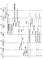
- the P-GW 20 receives a packet from a PDN (not shown) (step S101).
- the P-GW 20 encapsulates the received packet and transmits it to the S-GW 30 as a GTP-U packet or a GRE packet (step S102).
- the S-GW 30 sets the incoming call type information indicating the type of incoming packet in the P-GW 20 to “Downlink Data Notification” (step S103). Specifically, as described above, the S-GW 30 has at least one of bearer identification information, bearer QoS information, default bearer information, P-GW information, PDN connection information, flow identification information, and S-GW load information. Based on this, the incoming call type information is set.
- the S-GW 30 transmits “Downlink Data Notification” including incoming call type information to the MME 40 (step S104a).
- the MME 40 transmits “Downlink Data Notification Ack” indicating that fact to the S-GW 30 (step S 105 a).
- the MME 40 determines whether or not to call the UE 10 located in the radio zone of the E-UTRAN 2 based on the incoming call type information included in the “Downlink Data Notification” from the S-GW 30 (step S106a). With reference to FIG. 4, the calling process in step S106a will be described in detail.
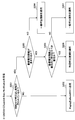
- FIG. 4 is a flowchart showing the calling process in the MME 40.
- step S201 when the MME 40 receives “Downlink Data Notification” from the S-GW 30, it determines whether or not call restriction is performed in the MME 40 (step S201).
- the call restriction is performed, for example, when the MME 40 is in a congested state or when an operator instructs to restrict the call to a specific subscriber unit or all subscribers. Note that this step can be omitted, and this flowchart may be started from step S203.
- the MME 40 transmits “Paging” for calling the UE 10 in an idle state to the eNodeB 50 (step S202).
- the MME 40 determines whether or not the incoming call type information is included in the “Downlink Data Notification” from the S-GW 30 (step S203).
- the MME 40 determines whether or not to send “Paging” for calling the idle UE 10 according to the general call restriction. Is determined (step S204).
- the general call restriction when the MME 40 is in a congested state or when a predetermined condition set by an operator is satisfied (for example, when a specific subscriber unit or all subscribers are designated), Transmission of “Paging” is canceled regardless of the incoming call type information.
- the MME 40 performs an incoming call failure process with the S-GW 30 or the P-GW 20.
- the MME 40 transmits “Paging” to the eNodeB 50 when transmission of “Paging” is not stopped according to the general call restriction.
- the MME 40 determines whether or not the incoming call should preferentially call the UE 10 based on the incoming call type information. Judgment is made (step S205).
- the MME 40 determines whether or not to transmit “Paging” for calling the UE 10 in the idle state according to the specific call restriction (step S205). S206). With such specific call restriction, transmission of “Paging” is stopped when the above-described incoming call type information satisfies a predetermined condition. When the transmission of “Paging” is stopped according to the specific call restriction, the MME 40 performs an incoming call failure process with the S-GW 30 or the P-GW 20. On the other hand, the MME 40 transmits “Paging” to the eNodeB 50 when the transmission of “Paging” is not stopped according to the specific call restriction.
- step S205 When it is determined that the incoming call is not to call the UE 10 preferentially (step S205; No), the MME 40 stops transmitting “Paging” for calling the UE 10 in the idle state in accordance with the general call restriction (step S207).
- the processing content of this step is the same as that of step S204, description is abbreviate
- the call determination process in the MME 40 is performed in step S106a of FIG. If the transmission of “Paging” is not stopped in step S206 of FIG. 4, the MME 40 transmits “Paging” to the eNodeB 50 (step S107a). In response to “Paging” from the eNodeB 50, the eNodeB 50 transmits “Paging” to the UE 10 located in the radio zone of the E-UTRAN 2 (step S108a).
- steps S104a to S108a The same processing as in steps S104a to S108a is also performed in steps S104b to S108b.
- the MME 40 and the eNodeB 50 in steps S104a to S108a correspond to the SGSN 60 and the RNC / BSC 70 in steps S104b to S108b, respectively.
- step S106b the call determination processing shown in steps S201 to S207 in FIG.
- the UE 10 When the UE 10 is located in the radio zone of the E-UTRAN 2, the UE 10 performs an incoming packet process between the eNodeB 50, the MME 40, and the S-GW 30 in accordance with “Paging” transmitted from the eNodeB 50 (step S109). Alternatively, when the UE 10 is located in the UTRAN / GERAN4 radio zone, the UE 10 performs an incoming packet process among the RNC / BSC 70, the SGSN 60, and the S-GW 30 in accordance with “Paging” transmitted from the SGSN 60.
- the S-GW 30 transmits “Stop Paging” requesting to stop transmission of “Paging” to both the MME 40 and the SGSN 60 (steps S110a and S110b).
- the S-GW 30 transmits the packet received in step S102 to the UE 10 via the eNodeB 50 (step S111a).
- the S-GW 30 sends the UE 10 via the SGSN 60 and the RNC / BSC 70 and the NodeB (not shown) or the RNC / BSC 70 and the NodeB (not shown). Then, the packet received in step S102 is transmitted (step S111b).
- the MME 40 and the SGSN 60 can determine whether or not to call the UE 10 based on the incoming call type information included in the “Donlink Data Notification”. Therefore, the MME 40 and the SGSN 60 can call the UE 10 depending on the content of the incoming call type information even in a situation where call regulation of the UE 10 is normally performed, for example, when the own device is in a congestion state.
- bearer identification information bearer identification information
- bearer QoS information default bearer information
- P-GW information PDN connection information
- flow identification information PDN connection information
- S-GW load information Since the incoming call type information is set based on at least one of the following, in the MME 40 and the SGSN 60 that are core network devices, for each bearer, for each bearer QoS, for each PDN connection, for each flow, or a combination thereof, etc. Whether or not to call the UE 10 can be determined under detailed conditions, and flexible call control can be performed.
- FIG. 5 is a functional configuration diagram of call processing in the mobile communication system according to the second embodiment. In FIG. 5, it is assumed that ISR is applied as in the first embodiment.
- the MME 40 that is a core network device provided in the EPC 1 is based on the incoming call type information included in the “Downlink Data Notification” from the S-GW 30, and the UE 10 located in the radio zone of the E-UTRAN 2 Call information for calling is set to “Paging”. Specifically, the MME 40 sets the call information based on at least one of the information determined by the incoming call type information and the capability information of the UE 10. The MME 40 transmits “Paging” including call information to the eNodeB 50.
- the information determined by the incoming call type information includes bearer identification information, bearer QoS information, default bearer information, P-GW information, PDN connection information, flow identification information, and S-GW load information. And at least one.
- the capability information of the UE 10 includes, for example, “UE Radio Access Capability” indicating the radio access capability of the UE 10.
- the call information may include at least one of the information determined by the incoming call type information and the capability information of the UE 10 as described above. Further, the call information may be a parameter associated with at least one of information determined by the incoming call type information and capability information of the UE 10. Examples of such parameters include call priority (for example, 1: priority high, 2: medium priority, 3: low priority 3) indicating the priority for calling the UE 10.
- the eNodeB 50 that is a radio access network device provided in the E-UTRAN 2 determines whether or not to call the UE 10 located in the radio zone of the E-UTRAN 2 based on the call information included in “Paging” from the MME 40. To do. When the eNodeB 50 is the predetermined incoming call type information, the eNodeB 50 transmits “Paging” to the UE 10.
- the SGSN 60 which is a core network device provided in the UMTS / GPRS core network 3 is located in the UTRAN / GERAN4 wireless zone based on the incoming call type information included in the “Downlink Data Notification” from the S-GW 30. Call information for calling the UE 10 is set to “Paging”. The SGSN 60 transmits “Paging” including call information to the RNC / BSC 70.
- the RNC / BSC 70 which is a radio access network device provided in the UTRAN / GERAN 4 calls the UE 10 located in the radio zone of the UTRAN / GERAN 4 based on the call information included in the “Paging” from the SGSN 60. Judging.
- the RNC / BSC 70 transmits “Paging” to the UE 10 when it is the predetermined incoming call type information.
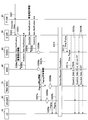
- steps S301 to S303, S304a to S305a, and S304b to S305b in FIG. 6 are the same as steps S101 to S103, S104a to S105a, and S104b to S105b in FIG.
- the MME 40 sets the calling information for calling the UE 10 in the idle state to “Paging” based on the incoming call type information included in the “Donlink Data Notification” from the S-GW 30 (Step S306a). Specifically, as described above, the MME 40 sets the call information based on at least one of the information determined by the incoming call type information and the capability information of the UE 10. The MME 40 transmits “Paging” including the call information to the eNodeB 50 (step S307a).
- the eNodeB 50 determines whether or not to call the UE 10 located in the radio zone of the E-UTRAN 2 based on the call information included in “Paging” from the MME 40 (step S308a).
- the call determination process in step S308a will be described in detail with reference to FIG.
- FIG. 7 is a flowchart showing a call determination process in the eNodeB 50.
- step S401 when the eNodeB 50 receives “Paging” from the MME 40, the eNodeB 50 determines whether or not call restriction is performed in the eNodeB 50 (step S401).
- the call restriction is performed, for example, when the eNodeB 50 is in a congested state or when the operator instructs to restrict the call to a specific subscriber unit or all subscribers. Note that this step can be omitted, and this flowchart may be started from step S403.
- step S401 If the call restriction is not performed in the eNodeB 50 (step S401; No), the eNodeB 50 transmits “Paging” for calling the UE 10 in the idle state (step S402).
- the eNodeB 50 determines whether or not call information is included in “Paging” from the MME 40 (step S403).
- the eNodeB 50 determines whether or not to transmit “Paging” for calling the UE 10 in the idle state according to the general call restriction (step S403). S404).
- the eNodeB 50 In the general call regulation, the eNodeB 50 is in a congested state, or when a predetermined condition set by the operator is satisfied (for example, when a specific subscriber unit or all subscribers are designated). Regardless of the call information, transmission of “Paging” is stopped.
- the eNodeB 50 performs an incoming call failure process with the MME 40, the S-GW 30, the P-GW 20, etc. when transmission of “Paging” is stopped in accordance with the general call restriction.
- the eNodeB 50 transmits “Paging” to the UE 10 when transmission of “Paging” is not stopped according to the general call restriction.
- the eNodeB 50 determines whether or not the call should be preferentially called from the UE 10 based on the call information (Step S403). S405).
- the eNodeB 50 determines whether or not to transmit “Paging” for calling the UE 10 in the idle state according to the specific call restriction (step S405). S406). With such specific call restriction, transmission of “Paging” is stopped when the above-described call information satisfies a predetermined condition.
- the eNodeB 50 performs an incoming call failure process with the MME 40, the S-GW 30, the P-GW 20, or the like when the transmission of “Paging” is stopped according to the specific call restriction. On the other hand, the eNodeB 50 transmits “Paging” to the UE 10 when transmission of “Paging” is not stopped according to the specific call restriction.
- step S405 When it is determined that it is not an incoming call that should call the UE 10 preferentially (step S405; No), the MME 40 determines whether or not to transmit “Paging” for calling the UE 10 in an idle state according to the general call restriction (step S405). S407). In addition, since the processing content of this step is the same as that of step S404, description is abbreviate
- step S308a of FIG. 6 the call determination process in the eNodeB 50 is performed.
- the eNodeB 50 transmits “Paging” to the UE 10 (step S309a).
- steps S306a to S309a are also performed in steps S306b to S309b.
- the MME 40 and the eNodeB 50 in steps S306a to S309a correspond to the SGSN 60 and the RNC / BSC 70 in steps S306b to S309b, respectively.
- step S308b it is assumed that the call determination processing shown in steps S401 to S407 in FIG. 7 is performed by the RNC / BSC 70.
- the MME 40 and the SGSN 60 respectively set the call information to “Paging” based on the incoming call type information included in “Donlink Data Notification” from the S-GW 30. Therefore, each of the eNodeB 50 and the RNC / BSC 70 can determine whether or not to call the UE 10 based on the call information included in “Paging”. Therefore, the eNodeB and the RNC / BSC 70 can call the UE 10 depending on the content of the call information even in a situation where the call restriction of the UE 10 is normally performed, for example, when the own device is in a congested state.
- information determined by the incoming call type information (bearer identification information, bearer QoS information, default bearer information, P-GW information, PDN connection information, flow Paging information is set based on at least one of identification information, S-GW load information, etc.) and capability information of the UE 10, so that, in the eNodeB 50 and the RNC / BSC 70, for each bearer, for each bearer QoS, Whether or not to call the UE 10 can be determined based on detailed conditions such as each PDN connection, each flow, or a combination thereof, and flexible call control can be performed.
- FIG. 8 is a functional configuration diagram of call processing in the mobile communication system according to the third embodiment.
- the S-GW 30 performs bearer identification information, bearer QoS information, default bearer information, P-GW information, PDN connection information, flow identification information, S-GW, Based on at least one of the GW load information, it is determined whether to call the UE 10 in an idle state.
- the S-GW 30 determines that the call should be made, the S-GW 30 transmits “Donlink Data Notification” to the MME 40 that is a core network device provided in the EPC 1.
- the S-GW 30 transmits “Donlink Data Notification” to the SGSN 60 that is a core network device provided in the UMTS / GPRS core network 3.
- the P-GW 20 notifies the S-GW 30 of packet type information indicating the type of the incoming packet, and the S-GW 30 changes the incoming call type information to “Donlink Data Notification” based on the packet type information.
- the P-GW 20 receives information on the received packet (for example, information set in the IP header of the received packet (for example, DSCP code point, transmission source server information (IP address, port number, etc.)), packet data
- the packet type information may be determined based on the contents (such as application information).
- FIG. 9 is a functional configuration diagram of call processing in the mobile communication system according to the first modification.
- the P-GW 20 receives a packet for the UE 10 in an idle state from a PDN (not shown).
- the P-GW 20 sets the packet type information indicating the type of the incoming packet in the GTP-U packet or GRE packet, and transmits the GTP-U packet or GRE packet to the S-GW 30.
- the packet type information notified from the P-GW 20 to the S-GW 30 may be set, for example, in a DSCP code point that is an IP header portion of an encapsulated GTP-U or GRE packet. In such a case, the packet type information is set to be expressed by the value of the DSCP code point.
- the S-GW 30 includes the packet type information from the P-GW 20, the bearer identification information, bearer QoS information, default bearer information, P-GW information, PDN connection information, flow identification information, S- Based on at least one of the GW load information, the incoming call type information is set to “Downlink Data Notification”.
- the first and second embodiments determine whether the core network device MME 40 and the SGSN 60 and the radio access network device eNodeB 50 and the RNC / BSC 70 call the UE 10 in an idle state is determined. It may be judged. Similarly, the first and third embodiments, the second and third embodiments, and the first to third embodiments may be combined to determine whether to call the UE 10 in an idle state. .
Landscapes
- Engineering & Computer Science (AREA)
- Computer Networks & Wireless Communication (AREA)
- Signal Processing (AREA)
- Mobile Radio Communication Systems (AREA)
- Data Exchanges In Wide-Area Networks (AREA)
Abstract
Description
<移動通信システムの概略構成>
図1は、第1の実施形態に係る移動通信システムの概略構成図である。図1に示すように、第1の実施形態に係る移動通信システムは、LTEなどの次世代通信方式と第2/第3世代通信方式との互換性を備えたシステムであり、次世代通信方式のコアネットワークであるEPC(Evolved Packet Core)1と、次世代通信方式の無線アクセスネットワークであるE-UTRAN2と、第2/第3世代通信方式のコアネットワークであるUMTS(Universal Mobile Telecommunications System)/GPRS(General Packet Radio Service)コアネットワーク3と、第2/第3世代通信方式の無線アクセスネットワークであるUTRAN/GERAN4と、から構成される。
以下、第1の実施形態では、コアネットワーク装置であるMME40及びSGSN60において、アイドル状態のUE10の呼び出し判断を行う場合について説明する。図2は、第1の実施形態に係る移動通信システムにおける呼び出し処理の機能構成図である。なお、図2では、E-UTRAN2とUTRAN/GERAN4との無線ゾーン間を移動するアイドル状態のUE10が位置登録エリアを更新する頻度を低減するためのISR(Idle State Reduction)が適用されているものとする。
次に、図3及び図4を参照し、以上のように構成された第1の実施形態に係る移動通信システムにおける呼び出し動作について説明する。なお、以下の動作には、上述のISRが適用されているものとする。
第1の実施形態に係る移動通信システムによれば、S-GW30が、P-GW20で着信されたアイドル状態のUE10に対するパケットの着信種別情報を「Donwlink Data notification」に設定するので、MME40とSGSN60とは、それぞれ、「Donwlink Data Notification」に含まれる着信種別情報に基づいて、UE10の呼び出しを行うべきか否かを判断できる。したがって、MME40やSGSN60は、例えば、自装置が輻輳状態である場合など通常UE10の呼び出し規制が行われる状況であっても、着信種別情報の内容によってはUE10の呼び出しを行うことができる。
第2の実施形態では、無線アクセスネットワーク装置(eNodeB50、RNC/BSC70)においてアイドル状態のUE10の呼び出し判断を行う場合について、第1の実施形態との相違点を中心に説明する。
図5は、第2の実施形態に係る移動通信システムにおける呼び出し処理の機能構成図である。なお、図5では、第1の実施形態と同様に、ISRが適用されているものとする。
次に、図6及び図7を参照し、以上のように構成された第2の実施形態に係る移動通信システムにおける呼び出し動作について説明する。なお、以下の動作には、ISRが適用されているものとする。また、図6のステップS301~S303、S304a~S305a、S304b~S305bは、図3のステップS101~S103、S104a~S105a、S104b~S105bと同様であるため、説明を省略する。
第2の実施形態に係る移動通信システムによれば、MME40とSGSN60とが、それぞれ、S-GW30からの「Donwlink Data Notification」に含まれる着信種別情報に基づいて呼出情報を「Paging」に設定するので、eNodeB50とRNC/BSC70とは、それぞれ、「Paging」に含まれる呼出情報に基づいて、UE10の呼び出しを行うべきか否かを判断できる。したがって、eNodeBやRNC/BSC70は、例えば、自装置が輻輳状態である場合など通常UE10の呼び出し規制が行われる状況であっても、呼出情報の内容によってはUE10の呼び出しを行うことができる。
第3の実施形態では、S-GW30においてアイドル状態のUE10の呼び出し判断を行う場合について、第1の実施形態との相違点を中心に説明する。
次に、第1乃至第3実施形態の変更例1について説明する。変更例1では、P-GW20が、着信したパケットの種別を示すパケット種別情報をS-GW30に通知し、S-GW30が、当該パケット種別情報に基づいて着信種別情報を「Donwlink Data Notification」に設定する。ここで、P-GW20は受信したパケットに関する情報(例えば、受信パケットのIPヘッダに設定される情報(例えばDSCPコードポイントや、送信元サーバ情報(IPアドレス、ポート番号等))や、パケットデータの内容(アプリケーション情報など)に基づいて、パケット種別情報を判断してもよい。
上述の実施形態を用いて本発明について詳細に説明したが、当業者にとっては、本発明が本明細書中に説明した実施形態に限定されるものではないということは明らかである。
Claims (12)
- 第1ゲートウェイ装置によってアイドル状態のユーザ端末に対するパケットが着信された場合に、該ユーザ端末の呼び出しを行う呼び出し方法であって、
第2ゲートウェイ装置が、前記第1ゲートウェイ装置で着信された前記パケットの着信種別情報を呼び出し要求信号に設定し、該呼び出し要求信号をコアネットワーク装置に送信する工程と、
前記コアネットワーク装置が、前記第2ゲートウェイ装置からの前記呼び出し要求信号に含まれる前記着信種別情報に基づいて、前記ユーザ端末の呼び出しを行うか否かを判断する工程と、
を有することを特徴とする呼び出し方法。 - 前記ユーザ端末の呼び出しを行うか否かを判断する工程において、前記コアネットワーク装置は、前記呼び出し要求信号に含まれる前記着信種別情報と該コアネットワーク装置の輻輳状態とに基づいて、前記ユーザ端末の呼び出しを行うか否かを判断することを特徴とする請求項1に記載の呼び出し方法。
- 前記着信種別情報は、前記パケットを伝送するためのベアラを識別するベアラ識別情報と、前記ベアラのQoSを示すベアラQoS情報と、の少なくとも一つに基づいて、設定されることを特徴とする請求項1又は請求項2に記載の呼び出し方法。
- 前記着信種別情報は、前記ベアラ識別情報と前記ベアラQoS情報とを含むことを特徴とする請求項1又は請求項2に記載の呼び出し方法。
- 第1ゲートウェイ装置によってアイドル状態のユーザ端末に対するパケットが着信された場合に、該ユーザ端末の呼び出しを行う呼び出し方法であって、
第2ゲートウェイ装置が、前記第1ゲートウェイ装置で着信された前記パケットの着信種別情報を呼び出し要求信号に設定し、該呼び出し要求信号をコアネットワーク装置に送信する工程と、
前記コアネットワーク装置が、前記第2ゲートウェイ装置からの前記呼び出し要求信号に含まれる前記着信種別情報に基づいて、前記ユーザ端末を呼び出すための呼出情報を呼び出し信号に設定し、該呼び出し信号を無線アクセスネットワーク装置に送信する工程と、
前記無線アクセスネットワーク装置が、前記コアネットワーク装置からの前記呼び出し信号に含まれる前記呼出情報に基づいて、前記ユーザ端末の呼び出しを行うか否かを判断する工程と、
を有することを特徴とする呼び出し方法。 - 前記着信種別情報は、前記パケットを伝送するためのベアラを識別するベアラ識別情報と、前記ベアラのQoSを示すベアラQoS情報と、の少なくとも一つに基づいて、設定されることを特徴とする請求項5に記載の呼び出し方法。
- 前記着信種別情報は、前記ベアラ識別情報と前記ベアラQoS情報とを含むことを特徴とする請求項6に記載の呼び出し方法。
- 前記呼出情報は、前記着信種別情報として設定された前記ベアラQoS情報に基づいて、設定されることを特徴とする請求項6又は請求項7に記載の呼び出し方法。
- 第1ゲートウェイ装置によってアイドル状態のユーザ端末に対するパケットが着信された場合に、該ユーザ端末の呼び出しを行うコアネットワーク装置であって、
前記第1ゲートウェイ装置に接続された第2ゲートウェイ装置から、前記パケットの着信種別を示す着信種別情報を含む呼び出し要求信号を受信し、
受信した前記呼び出し要求信号に含まれる前記着信種別情報に基づいて、前記ユーザ端末の呼び出しを行うか否かを判断することを特徴とするコアネットワーク装置。 - 前記コアネットワーク装置は、前記呼び出し要求信号に含まれる前記着信種別情報と該コアネットワーク装置の輻輳状態とに基づいて、前記ユーザ端末の呼び出しを行うか否かを判断することを特徴とする請求項9に記載のコアネットワーク装置。
- 第1ゲートウェイ装置によってアイドル状態のユーザ端末に対するパケットが着信された場合に、該ユーザ端末の呼び出しを行う無線アクセスネットワーク装置であって、
コアネットワーク装置が、前記第1ゲートウェイ装置に接続された第2ゲートウェイ装置から、前記パケットの着信種別を示す着信種別情報を含む呼び出し要求信号を受信した場合に、該コアネットワーク装置から、前記着信種別情報に基づいて設定された呼出情報を含む呼び出し信号を受信し、
前記コアネットワーク装置からの前記呼び出し信号に含まれる前記呼出情報に基づいて、前記ユーザ端末の呼び出しを行うか否かを判断することを特徴とする無線アクセスネットワーク装置。 - アイドル状態のユーザ端末に対するパケットが着信された場合に、コアネットワーク装置に対して呼び出し要求信号を送信するゲートウェイ装置であって、
前記パケットの着信種別情報を前記呼び出し要求信号に設定し、該呼び出し要求信号を前記コアネットワーク装置に送信することを特徴とするゲートウェイ装置。
Priority Applications (7)
| Application Number | Priority Date | Filing Date | Title |
|---|---|---|---|
| CN201080068449.1A CN103081547B (zh) | 2010-07-30 | 2010-12-28 | 呼叫方法、核心网络装置、无线接入网络装置以及网关装置 |
| BR112013002209A BR112013002209A2 (pt) | 2010-07-30 | 2010-12-28 | método de paging, aparelho de rede núcleo, aparelho de rádio de rede de acesso e aparelho de gateway |
| MX2013000993A MX2013000993A (es) | 2010-07-30 | 2010-12-28 | Metodo de localizacion, dispositivo de red central, dispositivo de red de acceso inalambrico, y dispositivo de puerta de enlace. |
| US13/812,143 US9544874B2 (en) | 2010-07-30 | 2010-12-28 | Paging method, core network apparatus, radio access network apparatus and gateway apparatus |
| CA2802418A CA2802418C (en) | 2010-07-30 | 2010-12-28 | Paging method, core network apparatus, radio access network apparatus and gateway apparatus |
| EP10855348.8A EP2600668B1 (en) | 2010-07-30 | 2010-12-28 | Paging method, core network device, wireless access network device, and gateway device |
| KR1020137002586A KR101278516B1 (ko) | 2010-07-30 | 2010-12-28 | 호출방법, 코어 네트워크 장치, 무선 액세스 네트워크 장치 및 게이트웨이 장치 |
Applications Claiming Priority (2)
| Application Number | Priority Date | Filing Date | Title |
|---|---|---|---|
| JP2010-172794 | 2010-07-30 | ||
| JP2010172794A JP4767357B1 (ja) | 2010-07-30 | 2010-07-30 | 呼び出し方法、コアネットワーク装置、無線アクセスネットワーク装置及びゲートウェイ装置 |
Publications (1)
| Publication Number | Publication Date |
|---|---|
| WO2012014342A1 true WO2012014342A1 (ja) | 2012-02-02 |
Family
ID=44693573
Family Applications (1)
| Application Number | Title | Priority Date | Filing Date |
|---|---|---|---|
| PCT/JP2010/073775 WO2012014342A1 (ja) | 2010-07-30 | 2010-12-28 | 呼び出し方法、コアネットワーク装置、無線アクセスネットワーク装置及びゲートウェイ装置 |
Country Status (9)
| Country | Link |
|---|---|
| US (1) | US9544874B2 (ja) |
| EP (1) | EP2600668B1 (ja) |
| JP (1) | JP4767357B1 (ja) |
| KR (1) | KR101278516B1 (ja) |
| CN (1) | CN103081547B (ja) |
| BR (1) | BR112013002209A2 (ja) |
| CA (1) | CA2802418C (ja) |
| MX (1) | MX2013000993A (ja) |
| WO (1) | WO2012014342A1 (ja) |
Cited By (4)
| Publication number | Priority date | Publication date | Assignee | Title |
|---|---|---|---|---|
| JP2015226140A (ja) * | 2014-05-27 | 2015-12-14 | 日本電気通信システム株式会社 | 無線通信システム、通信制御装置、通信方法、制御方法およびプログラム |
| EP2908582A4 (en) * | 2012-10-10 | 2016-06-15 | Lg Electronics Inc | PAGING PROCESSING METHOD AND METHOD FOR RETRIEVING DATA IN DOWNWARD DIRECTION |
| JP2016527822A (ja) * | 2013-07-29 | 2016-09-08 | エルジー エレクトロニクス インコーポレイティド | Imsサービスのためのページング方法及び装置 |
| US11006385B2 (en) | 2013-02-27 | 2021-05-11 | Huawei Technologies Co., Ltd. | Paging optimization method, apparatus, and system |
Families Citing this family (22)
| Publication number | Priority date | Publication date | Assignee | Title |
|---|---|---|---|---|
| JP5011439B2 (ja) * | 2011-01-07 | 2012-08-29 | 株式会社エヌ・ティ・ティ・ドコモ | 移動通信方法、移動管理ノード及びサービングゲートウェイ装置 |
| EP3490320B1 (en) | 2011-09-30 | 2023-08-23 | InterDigital Patent Holdings, Inc. | Device communication using a reduced channel bandwidth |
| WO2014000266A1 (zh) * | 2012-06-29 | 2014-01-03 | 华为技术有限公司 | 信息处理方法、转发面设备和控制面设备 |
| EP2876953B1 (en) * | 2012-07-20 | 2019-06-26 | NEC Corporation | Paging control apparatus, paging method and non-transitory computer-readable medium |
| RU2015105956A (ru) * | 2012-07-24 | 2016-09-10 | Телефонактиеболагет Л М Эрикссон (Пабл) | Узел и способ обработки запроса поискового вызова на основе приоритета приложения |
| US9351274B2 (en) * | 2012-07-24 | 2016-05-24 | Telefonaktiebolaget Lm Ericsson (Publ) | Node and method for priority of application based handling of a paging request |
| KR20140035785A (ko) * | 2012-09-14 | 2014-03-24 | 삼성전자주식회사 | 무선 통신 시스템에서 망 혼잡상황에서 특정 서비스를 제어하는 방법 및 장치 |
| EP4170986A1 (en) * | 2012-09-26 | 2023-04-26 | InterDigital Patent Holdings, Inc. | Pbch demodulation for new carrier type (nct) |
| KR101982204B1 (ko) * | 2012-09-28 | 2019-05-24 | 에스케이텔레콤 주식회사 | 다운링크 데이터 처리장치 및 방법 |
| KR20140071866A (ko) * | 2012-12-04 | 2014-06-12 | 에릭슨 엘지 주식회사 | 호 처리 제어 방법 및 장치 |
| CN104303466B (zh) * | 2013-05-15 | 2018-01-23 | 华为技术有限公司 | 一种数据传输方法、装置、通信设备及通信系统 |
| EP3047683A1 (en) * | 2013-09-16 | 2016-07-27 | Nokia Solutions and Networks Oy | User equipment access-based machine to machine communication mechanism |
| JP2016532337A (ja) * | 2013-09-29 | 2016-10-13 | 富士通株式会社 | ページング方法、ネットワーク装置及び通信システム |
| KR102084038B1 (ko) * | 2013-10-02 | 2020-03-03 | 에스케이 텔레콤주식회사 | 중요 데이터 패킷을 우선 처리하는 방법 및 장치 |
| US9999020B2 (en) | 2014-01-13 | 2018-06-12 | Lg Electronics Inc. | Downlink data transfer method and location update procedure execution method |
| JP6228470B2 (ja) * | 2014-01-21 | 2017-11-08 | 株式会社Nttドコモ | 通信システムおよび通信制御方法 |
| EP3145229B1 (en) | 2014-06-05 | 2020-03-11 | Huawei Technologies Co. Ltd. | Method and device for sending packet |
| US10531427B2 (en) | 2014-12-09 | 2020-01-07 | Qualcomm Incorporated | Enhanced system access for E-UTRAN |
| WO2017017173A1 (en) * | 2015-07-28 | 2017-02-02 | Deutsche Telekom Ag | Enhanced overload protection in a wireless telecommunications network |
| US10575278B2 (en) | 2015-10-23 | 2020-02-25 | Lg Electronics Inc. | Method for controlling idle-mode signaling reduction of terminal in wireless communication system and apparatus for the same |
| EP3443787A1 (en) * | 2016-04-15 | 2019-02-20 | Telefonaktiebolaget LM Ericsson (PUBL) | Methods and apparatus for paging an inactive ue in a wireless network |
| WO2020068049A1 (en) | 2018-09-25 | 2020-04-02 | Nokia Technologies Oy | System and method for saving mobile battery and empowering user equipment for incoming communication and paging |
Citations (2)
| Publication number | Priority date | Publication date | Assignee | Title |
|---|---|---|---|---|
| JP2009153141A (ja) * | 2008-12-24 | 2009-07-09 | Kyocera Corp | 無線加入者システム、無線加入者システムの回線接続制御装置及び記録媒体 |
| JP2010172794A (ja) | 2009-01-27 | 2010-08-12 | Panasonic Electric Works Co Ltd | 静電霧化装置 |
Family Cites Families (19)
| Publication number | Priority date | Publication date | Assignee | Title |
|---|---|---|---|---|
| US6731944B1 (en) * | 2000-05-17 | 2004-05-04 | Telefonaktiebolaget Lm Ericsson | Apparatus and method for automatically controlling the forwarding of low priority page requests |
| US20040157626A1 (en) * | 2003-02-10 | 2004-08-12 | Vincent Park | Paging methods and apparatus |
| EP1784035A1 (en) * | 2005-11-07 | 2007-05-09 | Alcatel Lucent | A method for connection re-establishment in a mobile communication system |
| CN101047949B (zh) * | 2006-03-27 | 2010-05-12 | 华为技术有限公司 | 业务数据流的承载控制方法 |
| US20080025250A1 (en) | 2006-07-28 | 2008-01-31 | Motorola, Inc. | Method and system for setting paging indication sequences in paging messages |
| US8295860B2 (en) * | 2007-03-13 | 2012-10-23 | Cisco Technology, Inc. | System and method for intelligent paging of an idle mobile device |
| CN101589566B (zh) * | 2007-06-18 | 2013-06-12 | Lg电子株式会社 | 在无线通信系统中执行上行链路同步的方法 |
| JP4733093B2 (ja) * | 2007-09-28 | 2011-07-27 | 株式会社エヌ・ティ・ティ・ドコモ | 無線通信システム及び無線通信方法 |
| CN101466083B (zh) | 2007-12-18 | 2010-12-08 | 华为技术有限公司 | 一种紧急呼叫方法和装置 |
| JP5154693B2 (ja) * | 2008-05-13 | 2013-02-27 | サムスン エレクトロニクス カンパニー リミテッド | 移動通信システムにおける音声呼提供方法及び装置とそのシステム |
| US9544873B2 (en) * | 2008-05-14 | 2017-01-10 | Qualcomm Incorporated | Paging with QoS in a wireless communication system |
| CN102217275A (zh) * | 2008-11-18 | 2011-10-12 | 思达伦特网络有限责任公司 | 无线网络中的选择性寻呼 |
| WO2010098146A1 (en) * | 2009-02-27 | 2010-09-02 | Panasonic Corporation | Method for a communication node with a plurality of communication interfaces to notify dynamic path setup and associated apparatus thereof |
| US8428625B2 (en) * | 2009-02-27 | 2013-04-23 | Cisco Technology, Inc. | Paging heuristics in packet based networks |
| US8515465B2 (en) * | 2009-09-02 | 2013-08-20 | Telefonaktiebolaget L M Ericsson (Publ) | Solution for paging differentiation in communication network |
| US8611895B2 (en) * | 2009-10-30 | 2013-12-17 | Apple Inc. | Methods for optimizing paging mechanisms using device context information |
| KR101650608B1 (ko) * | 2009-10-30 | 2016-08-23 | 인터디지탈 패튼 홀딩스, 인크 | 무선 통신을 위한 시그널링 |
| US8861535B2 (en) * | 2010-05-21 | 2014-10-14 | Cisco Technology, Inc. | Multi-tiered paging support using paging priority |
| BR112012032824A2 (pt) * | 2010-06-21 | 2016-11-08 | Ericsson Telefon Ab L M | método e arranjo para paginação em um sistema de comunicações sem fio |
-
2010
- 2010-07-30 JP JP2010172794A patent/JP4767357B1/ja active Active
- 2010-12-28 CN CN201080068449.1A patent/CN103081547B/zh active Active
- 2010-12-28 KR KR1020137002586A patent/KR101278516B1/ko active IP Right Grant
- 2010-12-28 US US13/812,143 patent/US9544874B2/en active Active
- 2010-12-28 EP EP10855348.8A patent/EP2600668B1/en active Active
- 2010-12-28 MX MX2013000993A patent/MX2013000993A/es active IP Right Grant
- 2010-12-28 CA CA2802418A patent/CA2802418C/en active Active
- 2010-12-28 WO PCT/JP2010/073775 patent/WO2012014342A1/ja active Application Filing
- 2010-12-28 BR BR112013002209A patent/BR112013002209A2/pt not_active IP Right Cessation
Patent Citations (2)
| Publication number | Priority date | Publication date | Assignee | Title |
|---|---|---|---|---|
| JP2009153141A (ja) * | 2008-12-24 | 2009-07-09 | Kyocera Corp | 無線加入者システム、無線加入者システムの回線接続制御装置及び記録媒体 |
| JP2010172794A (ja) | 2009-01-27 | 2010-08-12 | Panasonic Electric Works Co Ltd | 静電霧化装置 |
Non-Patent Citations (2)
| Title |
|---|
| "General Packet Radio Service (GPRS) enhancements for Evolved Universal Terrestrial Radio Access Network (E-UTRAN) access (Release9)", 3GPP TS 23.401 V9.5.0, June 2010 (2010-06-01), XP050441571 * |
| See also references of EP2600668A4 * |
Cited By (6)
| Publication number | Priority date | Publication date | Assignee | Title |
|---|---|---|---|---|
| EP2908582A4 (en) * | 2012-10-10 | 2016-06-15 | Lg Electronics Inc | PAGING PROCESSING METHOD AND METHOD FOR RETRIEVING DATA IN DOWNWARD DIRECTION |
| EP2908583A4 (en) * | 2012-10-10 | 2016-06-22 | Lg Electronics Inc | PAGING PROCESSING METHOD AND METHOD FOR RETRIEVING DATA IN DOWNWARD DIRECTION |
| US9838998B2 (en) | 2012-10-10 | 2017-12-05 | Lg Electronics Inc. | Method of processing downlink data notification message and server therefore |
| US11006385B2 (en) | 2013-02-27 | 2021-05-11 | Huawei Technologies Co., Ltd. | Paging optimization method, apparatus, and system |
| JP2016527822A (ja) * | 2013-07-29 | 2016-09-08 | エルジー エレクトロニクス インコーポレイティド | Imsサービスのためのページング方法及び装置 |
| JP2015226140A (ja) * | 2014-05-27 | 2015-12-14 | 日本電気通信システム株式会社 | 無線通信システム、通信制御装置、通信方法、制御方法およびプログラム |
Also Published As
| Publication number | Publication date |
|---|---|
| MX2013000993A (es) | 2013-04-03 |
| US9544874B2 (en) | 2017-01-10 |
| CA2802418C (en) | 2014-02-11 |
| CN103081547B (zh) | 2016-03-02 |
| JP2012034238A (ja) | 2012-02-16 |
| BR112013002209A2 (pt) | 2016-06-14 |
| KR101278516B1 (ko) | 2013-06-27 |
| EP2600668B1 (en) | 2015-10-28 |
| EP2600668A4 (en) | 2014-04-30 |
| CA2802418A1 (en) | 2012-02-02 |
| US20130170438A1 (en) | 2013-07-04 |
| CN103081547A (zh) | 2013-05-01 |
| KR20130019024A (ko) | 2013-02-25 |
| JP4767357B1 (ja) | 2011-09-07 |
| EP2600668A1 (en) | 2013-06-05 |
Similar Documents
| Publication | Publication Date | Title |
|---|---|---|
| JP4767357B1 (ja) | 呼び出し方法、コアネットワーク装置、無線アクセスネットワーク装置及びゲートウェイ装置 | |
| JP7485003B2 (ja) | データ伝送のための制御プレーンおよびユーザプレーンの選択 | |
| US9148882B2 (en) | Method for processing data associated with session management and mobility management | |
| CN106664597B (zh) | 通信系统 | |
| WO2019196761A1 (en) | At commands for 5g qos management | |
| US9787596B2 (en) | Maximum transmission unit size reporting and discovery by a user equipment | |
| WO2017170123A1 (en) | LOAD CONTROL FROM CONTROL PLANE CIoT EPS OPTIMISATION | |
| US11968565B2 (en) | User plane information reporting method and apparatus | |
| KR20100060800A (ko) | HeNB에서 단말에게 선택적으로 자원을 할당하기 위한 시스템 및 장치 | |
| JP2015053706A (ja) | 通信システムと通信制御方法 | |
| JP2016518040A (ja) | 無線通信端末および無線通信端末の動作方法 | |
| WO2010077190A1 (en) | Emergency call support during roaming | |
| TW202044905A (zh) | 增強封包交換域資料中斷機制的方法以及使用者設備 | |
| TW201208407A (en) | Overload control in a packet mobile communication system | |
| US9301207B2 (en) | Quality of service control | |
| JP2015527783A (ja) | 輻輳状態報告方法およびアクセス・ネットワーク装置 | |
| EP2469925B1 (en) | Base station device, base station control device, mobile terminal, communication system, and base station device control method | |
| KR101830224B1 (ko) | 패킷 트래픽 제어 방법 및 이를 위한 장치 | |
| JP6561838B2 (ja) | コアネットワークノード、基地局装置及びアクセスポイント | |
| JP2009260584A (ja) | 移動体通信システム、ノード装置及びそれらに用いるパケット着信時のトラフィック削減方法 |
Legal Events
| Date | Code | Title | Description |
|---|---|---|---|
| WWE | Wipo information: entry into national phase |
Ref document number: 201080068449.1 Country of ref document: CN |
|
| 121 | Ep: the epo has been informed by wipo that ep was designated in this application |
Ref document number: 10855348 Country of ref document: EP Kind code of ref document: A1 |
|
| ENP | Entry into the national phase |
Ref document number: 2802418 Country of ref document: CA |
|
| WWE | Wipo information: entry into national phase |
Ref document number: MX/A/2013/000993 Country of ref document: MX |
|
| ENP | Entry into the national phase |
Ref document number: 20137002586 Country of ref document: KR Kind code of ref document: A |
|
| NENP | Non-entry into the national phase |
Ref country code: DE |
|
| WWE | Wipo information: entry into national phase |
Ref document number: 2010855348 Country of ref document: EP |
|
| WWE | Wipo information: entry into national phase |
Ref document number: 13812143 Country of ref document: US |
|
| REG | Reference to national code |
Ref country code: BR Ref legal event code: B01A Ref document number: 112013002209 Country of ref document: BR |
|
| ENP | Entry into the national phase |
Ref document number: 112013002209 Country of ref document: BR Kind code of ref document: A2 Effective date: 20130129 |