WO2012011503A1 - ワイヤハーネス - Google Patents
ワイヤハーネス Download PDFInfo
- Publication number
- WO2012011503A1 WO2012011503A1 PCT/JP2011/066480 JP2011066480W WO2012011503A1 WO 2012011503 A1 WO2012011503 A1 WO 2012011503A1 JP 2011066480 W JP2011066480 W JP 2011066480W WO 2012011503 A1 WO2012011503 A1 WO 2012011503A1
- Authority
- WO
- WIPO (PCT)
- Prior art keywords
- wire harness
- shield member
- magnetic shield
- electromagnetic
- magnetic
- Prior art date
Links
Images

Classifications
-
- H—ELECTRICITY
- H05—ELECTRIC TECHNIQUES NOT OTHERWISE PROVIDED FOR
- H05K—PRINTED CIRCUITS; CASINGS OR CONSTRUCTIONAL DETAILS OF ELECTRIC APPARATUS; MANUFACTURE OF ASSEMBLAGES OF ELECTRICAL COMPONENTS
- H05K9/00—Screening of apparatus or components against electric or magnetic fields
- H05K9/0007—Casings
-
- B—PERFORMING OPERATIONS; TRANSPORTING
- B60—VEHICLES IN GENERAL
- B60R—VEHICLES, VEHICLE FITTINGS, OR VEHICLE PARTS, NOT OTHERWISE PROVIDED FOR
- B60R16/00—Electric or fluid circuits specially adapted for vehicles and not otherwise provided for; Arrangement of elements of electric or fluid circuits specially adapted for vehicles and not otherwise provided for
- B60R16/02—Electric or fluid circuits specially adapted for vehicles and not otherwise provided for; Arrangement of elements of electric or fluid circuits specially adapted for vehicles and not otherwise provided for electric constitutive elements
- B60R16/0207—Wire harnesses
- B60R16/0215—Protecting, fastening and routing means therefor
Definitions
- the present invention relates to a wire harness having both functions of an electromagnetic shield and a magnetic shield.
- a plurality of high-voltage wires are used for electrical connection between the battery and the inverter in an electric vehicle or a hybrid vehicle.
- a plurality of high-voltage electric wires are routed in the engine room at the front of the vehicle and in the rear of the vehicle, with the middle portion routed under the vehicle floor and both end portions penetrating the vehicle frame. Yes.
- the plurality of high-voltage electric wires are respectively inserted and protected by metal protective pipes over the entire length.
- the iron plate can shield the magnetic field generated by the high-voltage electric wire, but has a problem in that it restricts the route design of the high-voltage electric wire.
- the present invention has been made in view of the above-described circumstances, and an object thereof is to provide a magnetically shieldable wire harness that reduces restrictions on path design.
- a wire harness that includes one or a plurality of conductive paths and an electromagnetic shield member for electromagnetic shielding that covers the conductive paths, and includes a magnetic shield member for magnetic shielding outside or inside the electromagnetic shield member.
- the magnetic shield member is formed of at least one of a metal foil and a magnetic shield sheet, or formed of a tape material including the metal foil. Wire harness.
- the magnetic shield member for magnetic shielding is included in the configuration. Therefore, compared with the case where the magnetic shield is separately provided such as an iron plate on the floor, for example, in the path design. There is an effect that it is possible to reduce the restriction. Thereby, there exists an effect that the better wire harness which has both the function of an electromagnetic shield and a magnetic shield can be provided.
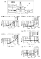
- FIG. 1 (a) to 1 (c) are diagrams showing a wire harness according to an embodiment of the present invention
- FIG. 1 (a) is a schematic diagram of an automobile
- FIG. 1 (b) is a configuration diagram of the wire harness
- FIG.1 (c) is principal part sectional drawing of a wire harness.
- 2A to 2F are diagrams relating to the magnetic shield characteristics.
- the wire harness according to the present embodiment is intended for wiring in a hybrid vehicle or an electric vehicle.
- a wire harness shall be comprised including the shield member of this embodiment.
- description will be made with reference to an example of a hybrid vehicle (the configuration, structure, and effects of the wire harness and the shield member of the present embodiment are basically the same even in the case of an electric vehicle). Note that this embodiment can be applied not only to a hybrid vehicle or an electric vehicle but also to an ordinary vehicle or the like).
- reference numeral 1 indicates a hybrid vehicle.
- the hybrid vehicle 1 is a vehicle that mixes and drives two powers of an engine 2 and a motor unit 3, and the motor unit 3 is supplied with electric power from a battery 5 (battery pack) via an inverter unit 4. It is like that.
- the engine 2, the motor unit 3, and the inverter unit 4 are mounted in an engine room 6 at a position where the front wheels and the like are located in the present embodiment.
- the battery 5 is mounted on the rear part 7 of the vehicle where there is a rear wheel or the like (it may be mounted in the vehicle room existing behind the engine room 6).
- the battery 5 and the inverter unit 4 are connected by a high-voltage wire harness 21 according to this embodiment.
- the motor unit 3 and the inverter unit 4 are also connected by a high-voltage wire harness 22.
- the wire harness 21 is routed on the indoor side of the floor panel.
- the wire harness 21 is manufactured to be long.
- the wire harness 22 is a so-called motor cable, and is manufactured to be much shorter than the wire harness 21.
- the well-known motor cable shall be used for the wire harness 22 of this embodiment, not only this but this invention may be applied.
- the motor unit 3 includes a motor and a generator.
- the inverter unit 4 includes an inverter and a converter in its configuration.
- the motor unit 3 is formed as a motor assembly including a shield case.
- the inverter unit 4 is also formed as an inverter assembly including a shield case.
- the battery 5 is of Ni-MH type or Li-ion type and is modularized. It is assumed that a power storage device such as a capacitor can be used.
- the battery 5 is not particularly limited as long as it can be used for the hybrid vehicle 1 and the electric vehicle.
- the battery 5 and the wire harness 21 are connected via the junction block 8 in this embodiment.
- the wire harness 21 that connects the battery 5 and the inverter unit 4 includes a wire harness main body 23, connection portions 24 provided at both ends of the wire harness main body 23, and the wire harness main body 23. And an exterior member 25 that protects the vehicle.
- a wire harness main body 23 connection portions 24 provided at both ends of the wire harness main body 23, and the wire harness main body 23.
- an exterior member 25 that protects the vehicle.
- the wire harness body 23 includes two high-voltage electric wires 26 (conductive paths), an electromagnetic shield member 27 that collectively accommodates the two high-voltage electric wires 26, and an outer (or inner) side of the electromagnetic shield member 27. And a magnetic shield member 28 provided in the above.
- the magnetic shield member 28 is provided at a desired location in the present embodiment.
- the magnetic shield member 28 is not limited to a plurality of locations, and may be a single location. Further, the electromagnetic shielding member 27 may be entirely covered. In addition, the number of high voltage electric wires 26 is not limited to the above two.
- the wire harness body 23 has both functions of an electromagnetic shield and a magnetic shield.
- the high voltage electric wire 26 is a conductive path including a conductor and an insulator (coating), and is formed to have a length necessary for electrical connection.
- the conductor is made of copper, copper alloy, or aluminum. Concerning the conductor, a conductor structure in which strands are twisted together or a rod-shaped conductor structure having a rectangular or round cross section (for example, a conductor structure having a flat single core or a round single core. It may be any of those that are rod-shaped).
- the high voltage electric wire 26 has a configuration to be an unshielded electric wire.
- the high-voltage electric wire 26 is used as the conductive path, but this is not limited to this. That is, a bus bar may be used, and in the case of a normal automobile or the like, a low-voltage wire bundle may be used.
- the electromagnetic shield member 27 is an electromagnetic shield member (electromagnetic wave countermeasure member) that covers the two high-voltage electric wires 26, and is formed into a cylindrical shape by a braid 29 having a large number of conductive ultrafine wires. ing.
- the electromagnetic shield member 27 is formed to have substantially the same length as the entire length of the two high-voltage electric wires 26.
- the electromagnetic shield member 27 is formed by the braid 29 in this embodiment, but is not limited to this. That is, as long as it is possible to take countermeasures against electromagnetic waves, for example, a shield member including a metal foil or a metal foil alone may be used.
- the magnetic shield member 28 provided for the electromagnetic shield member 27 as described above is provided to prevent the influence of the magnetic field. This is because the current flowing through the high-voltage electric wire 26 is a current that constantly changes in time (current having a relatively high frequency), and thus a magnetic field is generated.
- the magnetic shield member 28 is provided at least at a place where a magnetic shield is required.
- the magnetic shield member 28 is provided at a plurality of locations in the present embodiment, but is not limited thereto. That is, the magnetic shield member 28 may be provided over the entire electromagnetic shield member 27.
- the magnetic shield member 28 is formed of a metal foil. Or it is formed with the magnetic shielding sheet. Alternatively, they are formed by a combination thereof. Specific names include aluminum foil, copper foil sheet, iron foil sheet, high mu sheet, permalloy foil, and the like.
- the magnetic shield member 28 is formed by one or a plurality of windings. In the present embodiment, at least one turn is wound by a worship winding having a cross-sectional shape shown in FIG.
- the worship volume is an example in providing the magnetic shield member 28.
- the number of windings or the number of layers to be stacked is appropriately set in consideration of the attenuation amount from the magnetic shield characteristics shown in FIGS. 2 (b) to 2 (f).
- the attenuation in FIGS. 2B to 2F is measured using a test apparatus 51 having the configuration shown in FIG. Specifically, the amount of attenuation by inserting the magnetic shield member 28 between the loop coil 52 and the pickup coil 53 of the test apparatus 51 is measured.
- FIG. 2 (b) to FIG. 2 (f) the magnetic shield characteristics relating to aluminum foil, copper foil sheet, iron foil sheet, high mu sheet and permalloy foil are listed, but not limited to these.
- a cylindrical portion 30 surrounding the electromagnetic shield member 27 and an overlapping portion 31 serving as an overlapping portion are formed. It is like that.
- the magnetic shield member 28 is formed so that the overlapping portion 31 is formed along the cylindrical portion 30 when the overlapping portion 31 is tilted to one side so that the proximal end portion 32 of the overlapping portion 31 is bent. It has become.
- the magnetic shield member 28 may be formed in a tape shape. When formed in a tape shape, it can function as a binding member.
- the connecting portion 24 includes a terminal (not shown) provided at each end of the two high-voltage electric wires 26 and a shield shell 33 fixed to the shield case of the inverter unit 4 or the battery 5.
- the shield shell 33 is a metal member having conductivity, and in this embodiment, the terminal of the electromagnetic shield member 27 is connected and fixed by caulking.
- Reference numeral 34 indicates a caulking ring.
- the exterior member 25 is a member for protecting the wire harness body 23 in the wire harness 21 and may be a known corrugated tube, pipe member, protector, or the like. In addition, the setting of the exterior member 25 shall be arbitrary.
- the exterior member 25 has a structure that can be fixed to the vehicle body.
- the wire harness 21 of this embodiment can be magnetically shielded by itself. There is no need to take a major measure such as the entire or partial installation of one floor.
- the wire harness 21 of the present embodiment can be provided with a magnetic shield member 28 at a location where a magnetic shield is desired, and can use metal foil or the like according to the frequency, or can change the thickness and number.
- the wire harness 21 of this embodiment forms the magnetic shield member 28 with a metal foil or the like, and the electromagnetic shield member 27 is also formed of the braid 29, of course, it has flexibility. It can be easily bent even in the direction.
- the wire harness 21 of the present embodiment can improve workability since the magnetic shield member 28 can be wound later in this assembly process.
- the magnetic shield member 28 for the magnetic shield is included in the configuration in addition to the electromagnetic shield member 27, the effect that this can be facilitated with respect to the path design is achieved. Play.
- This embodiment has an effect that a better wire harness 21 can be provided.
- the wire harness includes a magnetic shield member for magnetic shield in its configuration. Moreover, the wire harness has both functions of an electromagnetic shield and a magnetic shield.
Landscapes
- Engineering & Computer Science (AREA)
- Mechanical Engineering (AREA)
- Microelectronics & Electronic Packaging (AREA)
- Insulated Conductors (AREA)
- Shielding Devices Or Components To Electric Or Magnetic Fields (AREA)
- Details Of Indoor Wiring (AREA)
Abstract
経路設計上の制約を低減する磁気シールド可能なワイヤハーネスを提供する。 ワイヤハーネス21は、ワイヤハーネス本体23と、このワイヤハーネス本体23の両端にそれぞれ設けられる接続部24と、ワイヤハーネス本体23を保護する外装部材25とを備えて構成されている。ワイヤハーネス本体23は、二本の高圧電線26と、この二本の高圧電線26を一括して収容する電磁シールド部材27と、電磁シールド部材27の外側に設けられる磁気シールド部材28とを備えて構成されている。磁気シールド部材28は、所望の箇所に設けられている。ワイヤハーネス本体23は、電磁シールド及び磁気シールドの両機能を兼ね備えている。
Description
本発明は、電磁シールド及び磁気シールドの両機能を兼ね備えてなるワイヤハーネスに関する。
電気自動車やハイブリッド自動車におけるバッテリーとインバータとの電気的な接続には、複数本の高圧電線が用いられている。例えば下記特許文献1において、複数本の高圧電線は、この中間部分が車両床下に配索されるとともに、両端部分が車両フレームを貫通して車両前部のエンジンルームや車両後部に配索されている。複数本の高圧電線は、この全長にわたり、各々、金属保護パイプに挿通・保護されている。
上記従来技術にあっては、複数本の高圧電線を配索するためとして、車両床下に対する固定作業や車両フレームに対する貫通作業等をする必要があることから、配索に係る作業性が良くないということが分かる。本願発明者は、貫通作業をする必要のない車室内への配索を考えている。
高圧電線は、これを車室内に配索すると、同じく車室内で近傍に配索される低圧電線や、同じく車室内に搭載される電子機器等に電磁ノイズの影響が出てしまうという虞がある。従って、電磁シールドをするための電磁シールド部材を高圧電線に対し設ける必要がある。また、高圧電線は、これに流れる電流が絶えず時間的に変化する電流(比較的高い周波数を持つ電流)であることから、発生する磁界によって車室内の例えば搭乗者に影響が出てしまうという虞がある。従って、磁気シールド機能を有する鉄板をフロアの全体又は部分的に設けるなどの対策が必要になる。
そこで、高圧電線に対し電磁シールド部材を設けるとともに、高圧電線に対し別体となる鉄板を上記フロアに設けることを考えてみると、特に上記鉄板に関しては次のような問題点を有している。すなわち、鉄板は高圧電線により発生する磁界をシールドすることができるようになるが、高圧電線の経路設計に関しては制約を出してしまうという問題点を有している。
本発明は、上記した事情に鑑みてなされたもので、経路設計上の制約を低減する磁気シールド可能なワイヤハーネスを提供することを目的とする。
本発明の上記目的は、下記構成により達成される。
(1) 一又は複数の導電路と、該導電路を覆う電磁シールド用の電磁シールド部材とを備えるとともに、該電磁シールド部材の外側又は内側に磁気シールド用の磁気シールド部材を備えるワイヤハーネス。
(1) 一又は複数の導電路と、該導電路を覆う電磁シールド用の電磁シールド部材とを備えるとともに、該電磁シールド部材の外側又は内側に磁気シールド用の磁気シールド部材を備えるワイヤハーネス。
(2) 上記(1)の構成のワイヤハーネスにおいて、前記磁気シールド部材が、少なくとも金属箔及び磁気遮蔽シートの何れか一方にて形成される、或いは前記金属箔を含むテープ材にて形成されるワイヤハーネス。
(3) 上記(2)の構成のワイヤハーネスにおいて、前記磁気シールド部材が、一又は複数の巻き付けにより形成されるワイヤハーネス。
上記(1)の構成のワイヤハーネスによれば、磁気シールドのための磁気シールド部材を構成に含むことから、例えばフロアの鉄板などのような別体で磁気シールドする場合と比べて、経路設計上の制約を低減することができるという効果を奏する。これにより、電磁シールド及び磁気シールドの両機能を兼ね備えたより良いワイヤハーネスを提供することができるという効果を奏する。
上記(2)、上記(3)の構成のワイヤハーネスによれば、磁気シールド部材としてのより良い一形態を提供することができるという効果を奏する。
以下、図面を参照しながら一実施形態を説明する。
本実施形態のワイヤハーネスは、ハイブリッド自動車又は電気自動車に配索されるものを対象にしている。ワイヤハーネスは、本実施形態のシールド部材を含んで構成されるものとする。以下では、ハイブリッド自動車での例を挙げて説明をするものとする(電気自動車の場合でも本実施形態のワイヤハーネス及びシールド部材の構成、構造、及び効果は基本的に同じであるものとする。尚、ハイブリッド自動車又は電気自動車に限らず、通常の自動車等でも本実施形態を適用することができるものとする)。
本実施形態のワイヤハーネスは、ハイブリッド自動車又は電気自動車に配索されるものを対象にしている。ワイヤハーネスは、本実施形態のシールド部材を含んで構成されるものとする。以下では、ハイブリッド自動車での例を挙げて説明をするものとする(電気自動車の場合でも本実施形態のワイヤハーネス及びシールド部材の構成、構造、及び効果は基本的に同じであるものとする。尚、ハイブリッド自動車又は電気自動車に限らず、通常の自動車等でも本実施形態を適用することができるものとする)。
図1(a)において、引用符号1はハイブリッド自動車を示している。ハイブリッド自動車1は、エンジン2及びモータユニット3の二つの動力をミックスして駆動する車両であって、モータユニット3にはインバータユニット4を介してバッテリー5(電池パック)からの電力が供給されるようになっている。エンジン2、モータユニット3、及びインバータユニット4は、本実施形態において前輪等がある位置のエンジンルーム6に搭載されている。また、バッテリー5は、後輪等がある自動車後部7に搭載されている(エンジンルーム6の後方に存在する自動車室内に搭載してもよいものとする)。
バッテリー5とインバータユニット4は、本実施形態に係る高圧のワイヤハーネス21により接続されている。また、モータユニット3とインバータユニット4も高圧のワイヤハーネス22により接続されている。ワイヤハーネス21は、フロアパネルの室内側に配索されている。ワイヤハーネス21は、長尺なものに製造されている。一方、ワイヤハーネス22は所謂モータケーブルであって、ワイヤハーネス21と比べると、格段に短尺なものに製造されている。尚、本実施形態のワイヤハーネス22は、公知のモータケーブルを用いるものとするが、これに限らず本発明を適用してもよいものとする。
ここで本実施形態での補足説明をすると、モータユニット3はモータ及びジェネレータを構成に含んでいるものとする。また、インバータユニット4は、インバータ及びコンバータを構成に含んでいるものとする。モータユニット3は、シールドケースを含むモータアッセンブリとして形成されるものとする。また、インバータユニット4もシールドケースを含むインバータアッセンブリとして形成されるものとする。バッテリー5は、Ni-MH系やLi-ion系のものであって、モジュール化してなるものとする。尚、例えばキャパシタのような蓄電装置を使用することも可能であるものとする。バッテリー5は、ハイブリッド自動車1や電気自動車に使用可能であれば特に限定されないものとする。バッテリー5とワイヤハーネス21は、本実施形態において、ジャンクションブロック8を介して接続されている。
図1(b)に示すように、バッテリー5とインバータユニット4とを繋ぐワイヤハーネス21は、ワイヤハーネス本体23と、このワイヤハーネス本体23の両端にそれぞれ設けられる接続部24と、ワイヤハーネス本体23を保護する外装部材25とを備えて構成されている。以下、各構成部材について説明をする。
ワイヤハーネス本体23は、二本の高圧電線26(導電路)と、この二本の高圧電線26を一括して収容する電磁シールド部材27と、電磁シールド部材27の外側(又は内側でもよいものとする)に設けられる磁気シールド部材28とを備えて構成されている。
磁気シールド部材28は、本実施形態において、所望の箇所に設けられている。磁気シールド部材28は、複数箇所に限らず一箇所であってもよいものとする。また、電磁シールド部材27全体を覆うようなものであってもよいものとする。この他、高圧電線26の本数も上記二本に限らないものとする。
ワイヤハーネス21は、ワイヤハーネス本体23が電磁シールド及び磁気シールドの両機能を兼ね備えている。
高圧電線26は、導体及び絶縁体(被覆)を含む導電路であって、電気的な接続に必要な長さを有するように形成されている。導体は、銅や銅合金やアルミニウムにより製造されている。導体に関しては、素線を撚り合わせてなる導体構造のものや、断面矩形又は丸形となる棒状の導体構造(例えば平角単心や丸単心となる導体構造であり、この場合、電線自体も棒状となる)のもののいずれであってもよいものとする。高圧電線26は、非シールド電線となる構成を有している。
本実施形態においては高圧電線26を導電路として用いているが、この限りでないものとする。すなわち、バスバーを用いてもよいし、通常の自動車等である場合には、低圧の電線束を用いてもよいものとする。
電磁シールド部材27は、二本の高圧電線26を覆う電磁シールド用の部材(電磁波対策用の部材)であって、導電性を有する極細の素線を多数有する編組29にて筒状に形成されている。電磁シールド部材27は、二本の高圧電線26の全長とほぼ同じ長さに形成されている。
電磁シールド部材27は、本実施形態において編組29にて形成されているが、この限りでないものとする。すなわち、電磁波対策をすることが可能であれば、例えば金属箔を含んで構成されるシールド部材、或いは金属箔単体などであってもよいものとする。
以上のような電磁シールド部材27に対し設けられる磁気シールド部材28は、磁界による影響を阻止するために備えられている。これは、高圧電線26に流れる電流が絶えず時間的に変化する電流(比較的高い周波数を持つ電流)であるからであり、このため磁界が発生するからである。
磁気シールド部材28は、少なくとも磁気シールドを必要とする箇所に設けられている。磁気シールド部材28に関し、本実施形態においては複数箇所に設けられているが、これに限らないものとする。すなわち、磁気シールド部材28が電磁シールド部材27の全体にわたって設けられるようなものあってもよいものとする。
磁気シールド部材28は、金属箔にて形成されている。又は磁気遮蔽シートにて形成されている。或いはこれらの組み合わせにて形成されている。具体的な名称としては、アルミ箔、銅箔シート、鉄箔シート、ハイミューシート、パーマロイ箔などが挙げられるものとする。磁気シールド部材28は、一又は複数の巻き付けにより形成されている。本実施形態においては、図1(c)に示す断面形状となる拝み巻にて少なくとも一周巻き付けられている。
尚、磁気シールド部材28を設けるに当たり、上記拝み巻は一例であるものとする。巻き付け回数は、又は、積層する枚数は、図2(b)~図2(f)に示す磁気シールド特性などから減衰量を考慮して適宜設定するものとする。図2(b)~図2(f)の減衰量は、図2(a)に示す構成の試験装置51を用いて測定されている。具体的には、試験装置51のループコイル52及びピックアップコイル53間に磁気シールド部材28を入れて減衰する量が測定されている。
例えば、厚さt=35μmの銅箔シートを3枚用いた磁気シールド部材28にあっては、図2(c)に示す如く周波数10kHzにおいて約20dBの減衰が得られることが分かる。すなわち、約20dBのシールド効果が得られることが分かる。図2(b)~図2(f)中には、アルミ箔、銅箔シート、鉄箔シート、ハイミューシート、パーマロイ箔に係る各磁気シールド特性が挙げられているが、これらに限らないものとする。
図1(c)に戻り、磁気シールド部材28は、上記の拝み巻をすると、電磁シールド部材27を囲むような筒状部30と、重ね合わせの部分となる重ね合わせ部31とが形成されるようになっている。また、磁気シールド部材28は、重ね合わせ部31の基端部32を折り曲げるようにして重ね合わせ部31を一方に倒すと、この重ね合わせ部31が筒状部30に沿って形成されるようになっている。
尚、磁気シールド部材28は、これをテープ状に形成して用いてもよいものとする。テープ状に形成した場合には、結束部材としても機能させることができるようになっている。
接続部24は、二本の高圧電線26の各端末に設けられる図示しない端子と、インバータユニット4やバッテリー5のシールドケースに固定されるシールドシェル33とを含んで構成されている。シールドシェル33は、導電性を有する金属部材であって、本実施形態においては電磁シールド部材27の端末が加締めにより接続・固定されるようになっている。引用符号34は加締めリングを示している。
外装部材25は、ワイヤハーネス21におけるワイヤハーネス本体23を保護するための部材であって、公知のコルゲートチューブやパイプ部材、或いはプロテクタ等が挙げられるものとする。尚、外装部材25の設定は任意であるものとする。外装部材25は、車体に対しての固定が可能となる構造を有している。
上記構成において、電磁シールド部材27にて二本の高圧電線26を一括収容するとともに、電磁シールド部材27における外側(又は内側)の所望位置に磁気シールド部材28を設けると、ワイヤハーネス本体23の組み付けが完了する。また、このワイヤハーネス本体23に対して接続部24と外装部材25とを設けると、ワイヤハーネス21の組み付けが完了する。
以上、図1(a)~図2(f)を参照しながら説明してきたように、本実施形態のワイヤハーネス21は、これ自身にて磁気シールドをすることができることから、例えば鉄板をハイブリッド自動車1のフロア全体又は部分的に設けるなどの大掛かりな対策をとる必要性はない。また、本実施形態のワイヤハーネス21は、磁気シールドをしたい箇所に磁気シールド部材28を設けることができるとともに、周波数に応じて金属箔等を使い分けたり、厚みや枚数を変えたりすることができる。さらに、本実施形態のワイヤハーネス21は、金属箔等で磁気シールド部材28を形成するとともに、電磁シールド部材27も編組29にて形成することから、可撓性を有するのは勿論のこと、どの方向へでも曲げ易くすることができる。さらにまた、本実施形態のワイヤハーネス21は、この組み付け工程において磁気シールド部材28を後巻きにすることが可能であることから、作業性の向上を図ることができる。
本実施形態のワイヤハーネス21によれば、電磁シールド部材27の他に磁気シールドのための磁気シールド部材28を構成に含んでいることから、経路設計に関してこれをし易くすることができるという効果を奏する。本実施形態は、より良いワイヤハーネス21の提供をすることができるという効果を奏する。
以上、本発明のワイヤハーネスを詳細にまた特定の実施形態を参照して説明したが、前述した実施形態は本発明の主旨を変えない範囲で種々変更実施可能なことは勿論である。
本出願は、2010年7月23日出願の日本特許出願(特願2010-165489)に基づくものであり、その内容はここに参照として取り込まれる。
本出願は、2010年7月23日出願の日本特許出願(特願2010-165489)に基づくものであり、その内容はここに参照として取り込まれる。
本発明によれば、磁気シールド用の磁気シールド部材を構成に含むワイヤハーネスになる。また、ワイヤハーネスは、電磁シールド及び磁気シールドの両機能を兼ね備える。
1…ハイブリッド自動車
2…エンジン
3…モータユニット
4…インバータユニット
5…バッテリー
6…エンジンルーム
7…自動車後部
8…ジャンクションブロック
21、22…ワイヤハーネス
23…ワイヤハーネス本体
24…接続部
25…外装部材
26…高圧電線(導電路)
27…電磁シールド部材
28…磁気シールド部材
29…編組
30…筒状部
31…重ね合わせ部
32…基端部
33…シールドシェル
34…加締めリング
2…エンジン
3…モータユニット
4…インバータユニット
5…バッテリー
6…エンジンルーム
7…自動車後部
8…ジャンクションブロック
21、22…ワイヤハーネス
23…ワイヤハーネス本体
24…接続部
25…外装部材
26…高圧電線(導電路)
27…電磁シールド部材
28…磁気シールド部材
29…編組
30…筒状部
31…重ね合わせ部
32…基端部
33…シールドシェル
34…加締めリング
Claims (3)
- 一又は複数の導電路と、該導電路を覆う電磁シールド用の電磁シールド部材とを備えるとともに、該電磁シールド部材の外側又は内側に磁気シールド用の磁気シールド部材を備えるワイヤハーネス。
- 請求項1に記載のワイヤハーネスにおいて、
前記磁気シールド部材が、少なくとも金属箔及び磁気遮蔽シートの何れか一方にて形成される、或いは前記金属箔を含むテープ材にて形成されるワイヤハーネス。 - 請求項2に記載のワイヤハーネスにおいて、
前記磁気シールド部材が、一又は複数の巻き付けにより形成されるワイヤハーネス。
Priority Applications (3)
| Application Number | Priority Date | Filing Date | Title |
|---|---|---|---|
| US13/811,432 US20130118800A1 (en) | 2010-07-23 | 2011-07-20 | Wire harness |
| CN2011800361729A CN103026425A (zh) | 2010-07-23 | 2011-07-20 | 线束 |
| EP11809673.4A EP2597653A4 (en) | 2010-07-23 | 2011-07-20 | HARNESS |
Applications Claiming Priority (2)
| Application Number | Priority Date | Filing Date | Title |
|---|---|---|---|
| JP2010165489A JP5766415B2 (ja) | 2010-07-23 | 2010-07-23 | ワイヤハーネス |
| JP2010-165489 | 2010-07-23 |
Publications (1)
| Publication Number | Publication Date |
|---|---|
| WO2012011503A1 true WO2012011503A1 (ja) | 2012-01-26 |
Family
ID=45496922
Family Applications (1)
| Application Number | Title | Priority Date | Filing Date |
|---|---|---|---|
| PCT/JP2011/066480 WO2012011503A1 (ja) | 2010-07-23 | 2011-07-20 | ワイヤハーネス |
Country Status (5)
| Country | Link |
|---|---|
| US (1) | US20130118800A1 (ja) |
| EP (1) | EP2597653A4 (ja) |
| JP (1) | JP5766415B2 (ja) |
| CN (1) | CN103026425A (ja) |
| WO (1) | WO2012011503A1 (ja) |
Cited By (2)
| Publication number | Priority date | Publication date | Assignee | Title |
|---|---|---|---|---|
| US20220032861A1 (en) * | 2020-07-29 | 2022-02-03 | Yazaki Corporation | Shielded electric wire and wire harness |
| DE102020133489A1 (de) | 2020-12-15 | 2022-06-15 | Audi Aktiengesellschaft | Bordnetz für ein Kraftfahrzeug und Kraftfahrzeug |
Families Citing this family (10)
| Publication number | Priority date | Publication date | Assignee | Title |
|---|---|---|---|---|
| JP5867613B2 (ja) * | 2012-10-05 | 2016-02-24 | 住友電装株式会社 | ワイヤハーネス |
| JP6610946B2 (ja) * | 2015-12-22 | 2019-11-27 | 住友電装株式会社 | シールド導電路 |
| JP6746932B2 (ja) * | 2016-02-05 | 2020-08-26 | 富士電機株式会社 | 放射線検出装置 |
| CN106004714A (zh) * | 2016-06-30 | 2016-10-12 | 合肥江淮新发汽车有限公司 | 一种汽车高压线束总成 |
| JP6700613B2 (ja) * | 2017-03-22 | 2020-05-27 | 株式会社オートネットワーク技術研究所 | 導電線 |
| JP2019096492A (ja) * | 2017-11-23 | 2019-06-20 | 株式会社オートネットワーク技術研究所 | アルミニウム系素線、撚線導体、編組線、および、ワイヤーハーネス |
| US10985538B2 (en) * | 2018-05-25 | 2021-04-20 | Leoni Bordnetz-Systeme Gmbh | System and method for reducing air volume in a splitter |
| JP6928855B2 (ja) * | 2019-03-18 | 2021-09-01 | 古河電気工業株式会社 | ワイヤーハーネス |
| CN113820549A (zh) * | 2020-06-19 | 2021-12-21 | 北京新能源汽车股份有限公司 | 一种车辆线束电场强度的检测方法及装置 |
| US11895814B1 (en) * | 2022-11-09 | 2024-02-06 | Hyundai Motor Corporation | Device for shielding electromagnetic wave |
Citations (4)
| Publication number | Priority date | Publication date | Assignee | Title |
|---|---|---|---|---|
| JPH06150732A (ja) * | 1992-11-02 | 1994-05-31 | Sumitomo Wiring Syst Ltd | ワイヤーハーネス |
| JP2004224156A (ja) | 2003-01-22 | 2004-08-12 | Honda Motor Co Ltd | 車両用電力ケーブル保持構造 |
| JP2007095322A (ja) * | 2005-09-27 | 2007-04-12 | Auto Network Gijutsu Kenkyusho:Kk | 同軸ケーブルおよびシールドワイヤハーネス |
| JP2010165489A (ja) | 2009-01-14 | 2010-07-29 | Hitachi Plasma Display Ltd | プラズマディスプレイパネル |
Family Cites Families (4)
| Publication number | Priority date | Publication date | Assignee | Title |
|---|---|---|---|---|
| US3624267A (en) * | 1970-09-28 | 1971-11-30 | Walter A Plummer | Wraparound electrical shielding jacket and method for wire harness |
| US5349133A (en) * | 1992-10-19 | 1994-09-20 | Electronic Development, Inc. | Magnetic and electric field shield |
| DE102004010113B4 (de) * | 2004-02-27 | 2011-10-06 | Iprotex Gmbh & Co. Kg | Schutzhülle zum Schutz vor elektromagnetischer Strahlung |
| US20080149899A1 (en) * | 2006-12-21 | 2008-06-26 | E. I. Du Pont De Nemours And Company | Foamable Fluoropolymer Composition |
-
2010
- 2010-07-23 JP JP2010165489A patent/JP5766415B2/ja active Active
-
2011
- 2011-07-20 EP EP11809673.4A patent/EP2597653A4/en not_active Withdrawn
- 2011-07-20 WO PCT/JP2011/066480 patent/WO2012011503A1/ja active Application Filing
- 2011-07-20 CN CN2011800361729A patent/CN103026425A/zh active Pending
- 2011-07-20 US US13/811,432 patent/US20130118800A1/en not_active Abandoned
Patent Citations (4)
| Publication number | Priority date | Publication date | Assignee | Title |
|---|---|---|---|---|
| JPH06150732A (ja) * | 1992-11-02 | 1994-05-31 | Sumitomo Wiring Syst Ltd | ワイヤーハーネス |
| JP2004224156A (ja) | 2003-01-22 | 2004-08-12 | Honda Motor Co Ltd | 車両用電力ケーブル保持構造 |
| JP2007095322A (ja) * | 2005-09-27 | 2007-04-12 | Auto Network Gijutsu Kenkyusho:Kk | 同軸ケーブルおよびシールドワイヤハーネス |
| JP2010165489A (ja) | 2009-01-14 | 2010-07-29 | Hitachi Plasma Display Ltd | プラズマディスプレイパネル |
Non-Patent Citations (1)
| Title |
|---|
| See also references of EP2597653A4 |
Cited By (3)
| Publication number | Priority date | Publication date | Assignee | Title |
|---|---|---|---|---|
| US20220032861A1 (en) * | 2020-07-29 | 2022-02-03 | Yazaki Corporation | Shielded electric wire and wire harness |
| US11691577B2 (en) * | 2020-07-29 | 2023-07-04 | Yazaki Corporation | Shielded electric wire including a conductor having outer diameter set based on thermal expansion and an insulator having thickness based on thermal expansion and wire harness |
| DE102020133489A1 (de) | 2020-12-15 | 2022-06-15 | Audi Aktiengesellschaft | Bordnetz für ein Kraftfahrzeug und Kraftfahrzeug |
Also Published As
| Publication number | Publication date |
|---|---|
| EP2597653A4 (en) | 2014-04-23 |
| EP2597653A1 (en) | 2013-05-29 |
| JP5766415B2 (ja) | 2015-08-19 |
| CN103026425A (zh) | 2013-04-03 |
| JP2012028162A (ja) | 2012-02-09 |
| US20130118800A1 (en) | 2013-05-16 |
Similar Documents
| Publication | Publication Date | Title |
|---|---|---|
| JP5766415B2 (ja) | ワイヤハーネス | |
| JP5722562B2 (ja) | シールド部材、ワイヤハーネス、及びワイヤハーネス製造方法 | |
| WO2014024895A1 (ja) | 多層同軸電線 | |
| WO2014014096A1 (ja) | ワイヤハーネス | |
| JP5864228B2 (ja) | 高圧導電路及びワイヤハーネス | |
| JP5957783B2 (ja) | ワイヤハーネス | |
| WO2012157771A1 (ja) | シールド電線 | |
| US20140284100A1 (en) | Wire harness | |
| WO2012026282A1 (ja) | ワイヤハーネス | |
| JP2011097692A (ja) | ワイヤハーネス | |
| JP5927693B2 (ja) | プロテクタ及びワイヤハーネス | |
| WO2013015333A1 (ja) | 高圧導電路及びワイヤハーネス | |
| JP5987207B2 (ja) | ワイヤハーネス用外装部材及びワイヤハーネス | |
| JP6080341B2 (ja) | ワイヤハーネス | |
| JP5906544B2 (ja) | ワイヤハーネス | |
| JP5835987B2 (ja) | ワイヤハーネス | |
| JP6028279B2 (ja) | ワイヤハーネス | |
| JP5841856B2 (ja) | ワイヤハーネス | |
| JP6163699B2 (ja) | ワイヤハーネス | |
| JP5920923B2 (ja) | ワイヤハーネス | |
| JP2009289640A (ja) | 自動車用のシールド線 | |
| JP6328594B2 (ja) | ワイヤハーネス | |
| JP2015167116A (ja) | ワイヤハーネス及びワイヤハーネスの製造方法 | |
| JP2016152713A (ja) | 外装部材及びワイヤハーネス |
Legal Events
| Date | Code | Title | Description |
|---|---|---|---|
| WWE | Wipo information: entry into national phase |
Ref document number: 201180036172.9 Country of ref document: CN |
|
| 121 | Ep: the epo has been informed by wipo that ep was designated in this application |
Ref document number: 11809673 Country of ref document: EP Kind code of ref document: A1 |
|
| WWE | Wipo information: entry into national phase |
Ref document number: 13811432 Country of ref document: US |
|
| NENP | Non-entry into the national phase |
Ref country code: DE |
|
| WWE | Wipo information: entry into national phase |
Ref document number: 2011809673 Country of ref document: EP |