WO2012011233A1 - Microwave heating device - Google Patents
Microwave heating device Download PDFInfo
- Publication number
- WO2012011233A1 WO2012011233A1 PCT/JP2011/003831 JP2011003831W WO2012011233A1 WO 2012011233 A1 WO2012011233 A1 WO 2012011233A1 JP 2011003831 W JP2011003831 W JP 2011003831W WO 2012011233 A1 WO2012011233 A1 WO 2012011233A1
- Authority
- WO
- WIPO (PCT)
- Prior art keywords
- heating
- microwave
- waveguide
- chamber
- antenna
- Prior art date
Links
- 238000010438 heat treatment Methods 0.000 title claims abstract description 490
- 230000005571 horizontal transmission Effects 0.000 claims abstract description 52
- 230000005570 vertical transmission Effects 0.000 claims abstract description 41
- 238000001816 cooling Methods 0.000 claims description 26
- 238000009423 ventilation Methods 0.000 claims description 20
- 230000005540 biological transmission Effects 0.000 claims description 19
- 230000005855 radiation Effects 0.000 claims description 16
- 239000000463 material Substances 0.000 claims description 8
- 230000002093 peripheral effect Effects 0.000 claims description 3
- 238000003756 stirring Methods 0.000 claims description 2
- 230000037361 pathway Effects 0.000 abstract 6
- 230000005611 electricity Effects 0.000 abstract 2
- 238000010411 cooking Methods 0.000 description 42
- 235000013305 food Nutrition 0.000 description 34
- 238000000034 method Methods 0.000 description 18
- 230000010355 oscillation Effects 0.000 description 11
- 239000002184 metal Substances 0.000 description 8
- 230000008878 coupling Effects 0.000 description 7
- 238000010168 coupling process Methods 0.000 description 7
- 238000005859 coupling reaction Methods 0.000 description 7
- 229910000831 Steel Inorganic materials 0.000 description 5
- 238000005452 bending Methods 0.000 description 5
- 239000010959 steel Substances 0.000 description 5
- 230000009471 action Effects 0.000 description 4
- 239000000919 ceramic Substances 0.000 description 4
- 230000008859 change Effects 0.000 description 4
- 239000004020 conductor Substances 0.000 description 4
- 239000000470 constituent Substances 0.000 description 4
- 238000001514 detection method Methods 0.000 description 3
- 238000009826 distribution Methods 0.000 description 3
- 230000005684 electric field Effects 0.000 description 3
- 230000006872 improvement Effects 0.000 description 3
- 238000009413 insulation Methods 0.000 description 3
- 239000010445 mica Substances 0.000 description 3
- 229910052618 mica group Inorganic materials 0.000 description 3
- 229910001220 stainless steel Inorganic materials 0.000 description 3
- 239000010935 stainless steel Substances 0.000 description 3
- 235000013611 frozen food Nutrition 0.000 description 2
- 239000011521 glass Substances 0.000 description 2
- 239000012212 insulator Substances 0.000 description 2
- 238000004519 manufacturing process Methods 0.000 description 2
- 239000004065 semiconductor Substances 0.000 description 2
- XLYOFNOQVPJJNP-UHFFFAOYSA-N water Substances O XLYOFNOQVPJJNP-UHFFFAOYSA-N 0.000 description 2
- 206010037660 Pyrexia Diseases 0.000 description 1
- 239000011248 coating agent Substances 0.000 description 1
- 238000000576 coating method Methods 0.000 description 1
- 238000010586 diagram Methods 0.000 description 1
- 239000003989 dielectric material Substances 0.000 description 1
- 238000001035 drying Methods 0.000 description 1
- 230000000694 effects Effects 0.000 description 1
- 239000002320 enamel (paints) Substances 0.000 description 1
- 239000000945 filler Substances 0.000 description 1
- 238000005286 illumination Methods 0.000 description 1
- 239000011810 insulating material Substances 0.000 description 1
- 230000007246 mechanism Effects 0.000 description 1
- 239000000203 mixture Substances 0.000 description 1
- 238000007747 plating Methods 0.000 description 1
- 230000008569 process Effects 0.000 description 1
- 238000007789 sealing Methods 0.000 description 1
- 239000000779 smoke Substances 0.000 description 1
- 238000003466 welding Methods 0.000 description 1
Images


Classifications
-
- H—ELECTRICITY
- H05—ELECTRIC TECHNIQUES NOT OTHERWISE PROVIDED FOR
- H05B—ELECTRIC HEATING; ELECTRIC LIGHT SOURCES NOT OTHERWISE PROVIDED FOR; CIRCUIT ARRANGEMENTS FOR ELECTRIC LIGHT SOURCES, IN GENERAL
- H05B6/00—Heating by electric, magnetic or electromagnetic fields
- H05B6/64—Heating using microwaves
- H05B6/70—Feed lines
- H05B6/707—Feed lines using waveguides
-
- H—ELECTRICITY
- H05—ELECTRIC TECHNIQUES NOT OTHERWISE PROVIDED FOR
- H05B—ELECTRIC HEATING; ELECTRIC LIGHT SOURCES NOT OTHERWISE PROVIDED FOR; CIRCUIT ARRANGEMENTS FOR ELECTRIC LIGHT SOURCES, IN GENERAL
- H05B6/00—Heating by electric, magnetic or electromagnetic fields
- H05B6/64—Heating using microwaves
- H05B6/642—Cooling of the microwave components and related air circulation systems
-
- H—ELECTRICITY
- H05—ELECTRIC TECHNIQUES NOT OTHERWISE PROVIDED FOR
- H05B—ELECTRIC HEATING; ELECTRIC LIGHT SOURCES NOT OTHERWISE PROVIDED FOR; CIRCUIT ARRANGEMENTS FOR ELECTRIC LIGHT SOURCES, IN GENERAL
- H05B6/00—Heating by electric, magnetic or electromagnetic fields
- H05B6/64—Heating using microwaves
- H05B6/647—Aspects related to microwave heating combined with other heating techniques
- H05B6/6473—Aspects related to microwave heating combined with other heating techniques combined with convection heating
-
- H—ELECTRICITY
- H05—ELECTRIC TECHNIQUES NOT OTHERWISE PROVIDED FOR
- H05B—ELECTRIC HEATING; ELECTRIC LIGHT SOURCES NOT OTHERWISE PROVIDED FOR; CIRCUIT ARRANGEMENTS FOR ELECTRIC LIGHT SOURCES, IN GENERAL
- H05B6/00—Heating by electric, magnetic or electromagnetic fields
- H05B6/64—Heating using microwaves
- H05B6/647—Aspects related to microwave heating combined with other heating techniques
- H05B6/6482—Aspects related to microwave heating combined with other heating techniques combined with radiant heating, e.g. infrared heating
-
- H—ELECTRICITY
- H05—ELECTRIC TECHNIQUES NOT OTHERWISE PROVIDED FOR
- H05B—ELECTRIC HEATING; ELECTRIC LIGHT SOURCES NOT OTHERWISE PROVIDED FOR; CIRCUIT ARRANGEMENTS FOR ELECTRIC LIGHT SOURCES, IN GENERAL
- H05B6/00—Heating by electric, magnetic or electromagnetic fields
- H05B6/64—Heating using microwaves
- H05B6/70—Feed lines
- H05B6/701—Feed lines using microwave applicators
-
- H—ELECTRICITY
- H05—ELECTRIC TECHNIQUES NOT OTHERWISE PROVIDED FOR
- H05B—ELECTRIC HEATING; ELECTRIC LIGHT SOURCES NOT OTHERWISE PROVIDED FOR; CIRCUIT ARRANGEMENTS FOR ELECTRIC LIGHT SOURCES, IN GENERAL
- H05B6/00—Heating by electric, magnetic or electromagnetic fields
- H05B6/64—Heating using microwaves
- H05B6/72—Radiators or antennas
- H05B6/725—Rotatable antennas
Definitions
- the present invention relates to a microwave heating apparatus that radiates microwaves to an object to be heated and performs dielectric heating, and more particularly to a cooking device that cooks food that is an object to be heated by dielectric heating.
- the basic configuration of a heating cooker using microwaves typified by a microwave oven is a heating chamber shielded so that microwaves do not leak outside, a magnetron that generates microwaves, and a magnetron And a waveguide for transmitting the microwave generated in the heating chamber to the heating chamber.
- the components other than the heating chamber, the magnetron, and the waveguide various configurations are used according to the method according to the purpose. For example, there are a lateral feeding method, a lower feeding method, an upper feeding method, a vertical feeding method, and the like depending on which direction the microwave is incident on the heating chamber, and the configuration differs depending on these feeding methods. .
- the food itself that is the object to be heated needs to be rotated in the heating chamber so that the distribution of microwaves is not biased.
- a so-called turntable method is used in the lateral feeding method.
- an upper power feeding method in which microwaves are incident from the ceiling surface and a vertical power feeding method in which microwaves are incident from both the bottom surface and the ceiling surface, etc.
- the antenna that is the power feeding unit provided at the coupling portion between the waveguide and the heating chamber is rotated to radiate the microwave.
- the so-called rotating antenna method for rotating the antenna in this way is used for the lower feeding method, the upper feeding method, and the vertical feeding method.
- the power supply method to be selected in the microwave oven is determined in consideration of not only the microwave oven function but also other functions such as an oven function, a grill function, and a steam function.
- an oven function e.g., a grill function
- a steam function e.g., a steam function
- the heating chamber becomes hot, and thus a dish on which food to be heated is placed.
- a plate made of a conductor having high heat resistance is used.
- the microwave is reflected by the conductive dish, so that the microwave in the heating chamber is different from the case where a dielectric dish such as glass or ceramic that transmits microwaves is used. Wave distribution is different.
- a conductor net may be used instead of a conductor dish.
- microwaves pass when the mesh is increased to some extent compared to the wavelength, and therefore the microwave distribution in the heating chamber changes depending on the net shape.
- the food as the object to be heated is a dielectric, so that microwaves can penetrate into the food and heat the food. Is possible.
- the microwave oven it is possible to set fire inside the food in a short time. Therefore, by cooperating the function of the microwave oven that heats the inside of the food and the function of the heater that bakes the surface of the food, it becomes possible to bake large foods or frozen foods in a short time.
- the microwave from the antenna serving as the feeding unit heats the heater
- the apparatus size of the heating cooker must be increased in order to dispose the microwave feeding structure and the power supply structure to the heater so as not to overlap each other.
- the microwave power supply configuration and the heater power supply configuration coexist, there is a problem that it is difficult to achieve both improvement in heating efficiency and downsizing of the apparatus.
- FIG. 10 is a front cross-sectional view showing a schematic configuration when a heater power supply configuration having a heater is further provided for a cooking device in which a general microwave power feeding configuration is provided on the upper side of the heating chamber.
- a heating chamber 101 for dielectrically heating food that is an object to be heated is provided inside a casing 100 that constitutes the appearance of the heating cooker.
- a heater 102 is provided at a vertical position inside the heating chamber 101.
- a microwave power feeding configuration such as a magnetron 103, a waveguide 104, a rotating antenna 105, and a motor 106 is disposed.
- the conventional cooking device configured as described above has a structure in which heat released from the heating chamber 101 is conducted through the waveguide 104 and is transmitted to the magnetron 103, and the magnetron is easily heated. As a result, in the conventional cooking, the temperature of the magnetron 103 is increased, and the microwave heating efficiency by the magnetron 103 is reduced. Further, in the conventional cooking device, since a part of the microwave radiated from the rotating antenna 105 to the inside of the heating chamber 101 heats the upper heater 102, there is a problem that the heating efficiency by the microwave is lowered. Was. Furthermore, since a microwave power feeding configuration is disposed in the space above the heating chamber 101, a considerably large space is required above the heating chamber 101, and the size of the housing 100 has to be large. There was also a problem.
- the present invention provides a microwave heating apparatus with high heating efficiency by suppressing the temperature rise of the magnetron due to heat from the heating chamber, and at the same time, the microwave power feeding configuration disposed on the upper side of the heating chamber is made compact.
- An object is to provide a small microwave heating apparatus.
- the microwave heating apparatus is A heating chamber for storing an object to be heated, for radiating microwaves to the object to be heated and for high-frequency heating; A microwave generator for generating microwaves for high-frequency heating of the object to be heated in the heating chamber; A horizontal transmission path bent at right angles; and a vertical transmission path.
- the microwave generator is horizontally connected to the vertical transmission path, and a microwave is transmitted from the microwave generator to the horizontal transmission path.
- a wave tube A power feeding unit having an antenna unit coupled to the horizontal transmission path and radiating microwaves transmitted through the waveguide into the heating chamber;
- An antenna that is provided on the ceiling surface of the heating chamber, reflects a microwave radiated in a horizontal direction from the antenna unit, and is opened at a lower end so that the microwave from the antenna unit is radiated into the heating chamber.
- a room, and The waveguide is configured such that a horizontal transmission distance in the horizontal transmission path is longer than 1 ⁇ 2 of a microwave wavelength transmitted through the waveguide.
- the microwave heating device of the first aspect of the present invention configured as described above, the horizontal transmission distance from the bending position in the waveguide to the feeding port has the microwave wavelength transmitted through the waveguide.
- the microwave heating apparatus Since it is longer than 1 ⁇ 2, the coupling of transmission between the microwave generation unit and the power feeding unit is stable, and heating can be maintained with high efficiency even when the operation state such as a load change fluctuates.
- heat transfer from the heating chamber to the magnetron is suppressed by the waveguide having a long horizontal transmission path.
- a microwave generator for example, a magnetron is horizontally connected horizontally to the vertical transmission path of the waveguide. The size in the vertical direction can be made compact.
- the microwave heating apparatus is provided with a radiant heating section that heats an object to be heated by radiant heat from above in the heating chamber according to the first aspect.
- the radiation heating unit is disposed in a region other than directly below the antenna room. According to the microwave heating apparatus of the second aspect of the present invention configured as described above, the microwave radiated from the power feeding unit does not directly heat the radiant heating unit, and heating loss is prevented. Thus, the heating efficiency is improved.
- a convection heating unit that circulates hot air inside the heating chamber is provided to heat the object to be heated. It has been.
- the microwave heating device of the third aspect of the present invention configured as described above, heat transfer from the heating chamber to the magnetron is suppressed, and heat treatment with hot air in the heating chamber reduces heating loss. It can prevent and can carry out with high heating efficiency.
- the antenna section of the power feeding section according to the first to third aspects rotates inside the antenna chamber, and with respect to the inside of the heating chamber.
- the microwave is agitated and radiated.
- the microwave heating device of the 4th mode concerning the present invention constituted as mentioned above, it becomes possible to radiate a microwave uniformly to the whole heating chamber.
- the vertical transmission path extends downward with respect to the horizontal transmission path, and the heating A feeding port of the horizontal transmission path is coupled to an opening at an upper end portion of the antenna chamber formed to protrude upward from the ceiling surface of the chamber.
- the antenna chamber protruding from the heating chamber is configured to be offset to the vertical dimension of the waveguide. For this reason, there is no wasted space in the microwave power feeding configuration, and compactness can be achieved.
- the microwave heating device of the fifth aspect of the present invention since the waveguide is connected to the heating chamber via the antenna chamber, the contact portion between the waveguide and the heating chamber In addition, since the heat transmitted from the heating chamber to the microwave generation unit is reduced, the heating efficiency by the microwave generation unit is improved.
- the vertical transmission path extends upward with respect to the horizontal transmission path, and the heating A feed port of the horizontal transmission path is coupled to an opening at an upper end portion of the antenna chamber formed so as to protrude upward from the ceiling surface of the chamber, and the microwave from the microwave generation unit horizontally connected to the vertical transmission path A wave is radiated from the power feeding unit into the heating chamber via the horizontal transmission path.
- the microwave heating device according to the sixth aspect of the present invention configured as described above can construct a compact microwave power feeding configuration.
- a heat insulating portion is provided in a space between the waveguide and the heating chamber outside the antenna chamber in the first to fourth aspects. ing.
- the microwave heating device of the seventh aspect of the present invention configured as described above, the amount of heat transferred from the heating chamber during high-temperature heating to the microwave generation unit via the waveguide is greatly suppressed. Thus, the output efficiency of the microwave generation unit can be improved.
- the antenna chamber according to the first to fourth aspects includes a shielding wall protruding downward from the ceiling surface of the heating chamber,
- the said radiation heating part is arrange
- the microwave from the power feeding unit does not directly heat the radiant heating unit, and loss in the radiant heating unit is reduced.
- the object to be heated can be heated with high efficiency, and the size in the height direction of the entire apparatus is reduced, resulting in a compact configuration.
- a through-hole having a diameter at which microwaves do not leak is formed on the opposing surfaces of the waveguide according to the first to fourth aspects, and cooling is performed.
- the cooling air formed by the fan is configured to pass through the through hole.
- a ventilation region having a plurality of through holes having a diameter at which microwaves do not leak is formed in the waveguide according to the first to fourth aspects.
- the microwave heating device of the tenth aspect of the present invention configured as described above, the heat transfer resistance on the wall surface of the waveguide increases, and the cooling air flows through the through hole in the ventilation region.
- the wave tube is cooled, and the heat transmitted from the heating chamber to the microwave generation unit via the waveguide is reduced. As a result, the microwave heating efficiency is improved by the microwave generator.
- the vertical transmission path extends downward with respect to the horizontal transmission path, and the heating A feed port of the horizontal transmission path is coupled to an opening at an upper end portion of the antenna room formed so as to protrude upward from the ceiling surface of the room, and a microwave is placed in a space between the antenna room and the vertical transmission path.
- a generation unit is arranged.
- the waveguide is sandwiched between the vertical transmission path of the waveguide and the antenna chamber in the extending direction of the horizontal transmission path of the waveguide. Since the microwave generator is placed in the space generated below the horizontal transmission path, the upper space of the heating chamber can be used efficiently, eliminating wasted space and making the cooking device compact. Is planned.
- the waveguide according to the first to fourth aspects is configured such that a vertical transmission distance in the vertical transmission path has a microwave wavelength transmitted through the waveguide. It is configured to be shorter than 1 ⁇ 4. According to the microwave heating apparatus of the twelfth aspect of the present invention configured as described above, the electric field does not reverse in the vertical transmission path, and complicated reflection occurs in the waveguide transmission path. Occurrence can be prevented and transmission efficiency is improved.
- the present invention it is possible to provide a microwave heating apparatus in which the heating efficiency is improved and the microwave power supply configuration disposed on the upper side of the heating chamber is made compact to reduce the apparatus size.
- Front sectional drawing which shows the internal structure of the principal part in the heating cooker of Embodiment 1 which concerns on this invention.
- the perspective view which shows the waveguide and antenna chamber in the heating cooker of Embodiment 1 which concerns on this invention.
- Front sectional drawing which shows the internal structure of the principal part in the heating cooker of Embodiment 2 which concerns on this invention.
- the rear view which shows the electric power feeding part provided in the ceiling surface of the heating chamber in the heating cooker of Embodiment 2 which concerns on this invention, a heating part, etc.
- Front sectional drawing which shows the microwave electric power feeding structure in the heating cooker of Embodiment 3 which concerns on this invention
- Front sectional drawing which shows the microwave electric power feeding structure in the heating cooker of Embodiment 4 which concerns on this invention.
- Front sectional drawing which shows the microwave electric power feeding structure in the heating cooker of Embodiment 5 which concerns on this invention.
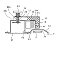
- Front sectional drawing which shows the microwave electric power feeding structure in the heating cooker of Embodiment 6 which concerns on this invention
- Front sectional view showing a schematic configuration of a general microwave feeding configuration in a heating cooker
- the microwave heating apparatus of the present invention a description will be given using a heating cooker.
- the heating cooker is an example, and the microwave heating apparatus of the present invention is not limited to the heating cooker.
- a heating device using dielectric heating which is high-frequency heating, a garbage processing machine, or a heating device such as a semiconductor manufacturing device. Therefore, the present invention is not limited to the specific configurations of the following embodiments, but includes configurations based on the same technical idea.
- Embodiment 1 As Embodiment 1 which concerns on this invention, the heating cooker in a microwave heating apparatus is demonstrated.
- a microwave oven including at least one heater as a heating unit will be described as an example of a heating cooker.
- FIG. 1 is a front sectional view showing an internal configuration of a main part in a heating cooker as a microwave heating apparatus according to a first embodiment of the present invention.
- a heating chamber 11 for dielectrically heating (high-frequency heating) a food 15 that is an object to be heated is provided inside a casing 10 that forms the appearance of the cooking device. That is, in the heating chamber 11, the food 15 that is the object to be heated is stored, and microwaves are radiated to the food 15 to be heated at high frequency.
- Two heaters 12 and 13 which are radiant heating portions for increasing the temperature of the heating chamber are provided inside the heating chamber 11 formed of a steel plate whose surface is enameled.
- One heater 12 is disposed on the ceiling surface side (upper side) of the heating chamber 11, and the other heater 13 is disposed on the bottom surface side (lower side) of the heating chamber 11.
- a grill 14 formed by combining stainless steel rods vertically and horizontally and welding is provided inside the heating chamber 11.
- the grill 14 is configured to be mounted at a plurality of desired positions in the heating chamber 11.
- the food 15 that is an object to be heated placed on the grill 14 is sandwiched between the upper heater 12 and the lower heater 13 and radiantly heated from above and below.
- the corners of the connecting portions between the wall surfaces constituting the heating chamber 11 are formed by curved surfaces. Further, the entire bottom surface of the heating chamber 11 is formed in a curved shape having a large radius of curvature.
- the wall surface demonstrates in the example formed with the steel plate which performed the enamel coating, you may form with the steel plate which applied the coating which has another heat resistance.
- the wall material may be stainless steel or PCM steel plate (Pre-coated metal).
- the grill 14 is formed by combining stainless steel rods, but can also be formed by using a steel material or the like subjected to plating.
- an antenna chamber 24 is provided near the center of the ceiling surface of the heating chamber 11, and a rotating antenna power feeding unit 22 as a radio wave agitating unit is disposed inside the antenna chamber 24.
- the antenna chamber 24 is made of a material that reflects the microwave radiated from the power feeding unit 22, and has a shielding structure so that the microwave does not leak outside the antenna chamber 24.
- the feeding portion 22 of the rotating antenna is provided so as to be led out from a feeding port 25 formed in the waveguide 21.
- the waveguide 21 transmits the microwave from the magnetron 16 that is the microwave generation unit to the power supply unit 22.
- the magnetron 16 generates microwaves for high-frequency heating of the food 15 that is the object to be heated in the heating chamber 11.
- the microwave transmitted to the power feeding unit 22 is radiated into the heating chamber 11.
- the magnetron 16 is disposed at the right end (see FIG. 1) of the waveguide 21 disposed on the upper side of the heating chamber 11, and the magnetron output unit 44 that is an oscillation antenna of the magnetron 16 with respect to the waveguide 21. Is inserted sideways.
- one heating means has a dielectric heating part by microwaves
- another heating means has a radiation heating part by radiation by the upper and lower heaters 12 and 13.
- the heating cooker of Embodiment 1 is the structure which performs the desired heat cooking with respect to the foodstuff 15 which is the to-be-heated object in the heating chamber 11 by using a dielectric heating part and a radiation heating part together.
- a description will be given of a configuration having a dielectric heating unit using microwaves as one heating unit and a radiation heating unit using upper and lower heaters 12 and 13 as another heating unit.
- a convection heating unit that performs cooking by circulating hot air in the heating chamber may be provided.
- a circulation fan and a circulation heater are provided on the back side of the heating chamber, and the air in the heating chamber is heated to a high temperature and circulated.
- it may be configured to perform cooking by providing three heating means including a dielectric heating unit, a radiation heating unit, and a convection heating unit.
- the upper and lower heaters 12 and 13 that are the radiant heating section in the first embodiment are configured by sealing a heating wire together with a filler in a metal pipe.
- An upper heater thermocouple 17 that contacts the surface of the upper heater 12 is provided in the heating chamber 11.
- the upper heater thermocouple 17 is covered with a metal tube so as not to be affected by the microwave radiated from the power supply unit 22, and functions as a temperature detection unit of the upper heater 12.
- a lower heater thermocouple 18 that contacts the surface of the lower heater 13 is provided in the heating chamber 11, and has the same configuration as the upper heater thermocouple 17.
- the lower heater thermocouple 18 functions as temperature detection means for the lower heater 13.
- a thermistor 19 is fixed to the wall surface of the heating chamber 11 as temperature detecting means in the heating chamber.
- the upper heater thermocouple 17, the lower heater thermocouple 18, and the thermistor 19 are electrically connected to a control unit 20 that is a control means.
- the control unit 20 controls the energization amount to the upper heater 12 and the lower heater 13 based on detection signals from the upper heater thermocouple 17, the lower heater thermocouple 18, and the thermistor 19.
- the heating control for the heating chamber 11 is controlled with high accuracy so that the heating amount becomes the set temperature.
- the upper heater 12 of the radiant heating section that heats the food 15 that is the object to be heated by radiant heat from above is disposed in a region other than directly below the antenna chamber 24. That is, the upper heater 12 is not directly irradiated by the microwave radiated from the power feeding unit 22 that is the rotating antenna in the antenna chamber 24, and the food 15 that is the object to be heated is directly irradiated. .
- the waveguide 21 provided on the upper side of the heating chamber 11 includes a horizontal portion 42 extending in the horizontal direction and a vertical portion 43 extending in the vertical direction. That is, the waveguide 21 is an L-shaped internal passage (transmission) bent at a right angle by a horizontal transmission path (42) formed by the horizontal section 42 and a vertical transmission path (43) formed by the vertical section 43. Road).
- a magnetron 16 that is a microwave generation unit is connected to a vertical unit 43 of the waveguide 21 by inserting a magnetron output unit 44 that is an oscillation antenna in a horizontal direction. Accordingly, since the magnetron 16 is connected laterally (horizontal connection) with respect to the waveguide 21, the vertical height dimension is such that the magnetron 16 is connected vertically to the waveguide 21 (vertical connection: This is shorter than the case of FIG.
- the feeding port 25 formed in the horizontal portion 42 (horizontal transmission path) of the waveguide 21 having the L-shaped internal passage (transmission path) is provided with the feeding section 22 that is a rotating antenna.
- the power feeding unit 22 includes an antenna unit 22a and a shaft unit 22b.
- a shaft portion 22 b of the power feeding unit 22 is connected to the motor 23.
- the shaft portion 22b is rotated by driving the motor 23, and the antenna portion 22a rotates.
- the power feeding unit 22 is coupled to the horizontal transmission path (42) of the waveguide 21, and the microwave transmitted through the waveguide 21 is radiated into the heating chamber 11 by the antenna unit 22 a of the power feeding unit 22.
- a dome-shaped antenna chamber 24 that houses the rotating antenna portion 22a is provided.
- the antenna chamber 24 has a shape in which a lower end portion extends in a circular shape, and has a truncated cone shape.
- the antenna chamber 24 is formed in a truncated cone shape by projecting the ceiling surface of the heating chamber 11 outward by drawing.
- a feeding port 25 formed on the lower surface of the horizontal portion 42 of the waveguide 21 is coupled to an opening formed at the upper end of the antenna chamber 24, and a coupling portion between the waveguide 21 and the feeding unit 22 is A predetermined diameter is secured as a power supply port.
- the antenna chamber 24 is provided on the ceiling surface of the heating chamber 11 and is configured to reflect the microwave radiated from the antenna portion 22a in the horizontal direction.
- the lower end portion of the antenna chamber 24 is opened so that the microwave from the antenna portion 22a is radiated into the heating chamber.
- FIG. 2 is a perspective view showing the waveguide 21 and the antenna chamber 24 in the cooking device of the first embodiment.
- the waveguide 21 has a horizontal portion 42 that forms a horizontal transmission path and a vertical portion 43 that forms a vertical transmission path, and an internal passage serving as a transmission path is L-shaped. It has a bent shape that is bent at a right angle. That is, the extending direction (horizontal direction) of the horizontal transmission path (42) and the extending direction (vertical direction) of the vertical transmission path (43) are orthogonal to each other.
- the waveguide 21 has the horizontal transmission path (42) and the vertical transmission path (43) bent at right angles, and the magnetron 16 serving as the microwave generation unit is horizontally disposed on the vertical transmission path (43). They are connected to transmit the microwave from the magnetron 16 to the horizontal transmission path (42).
- the distance H is set to about 135 mm.
- the horizontal transmission distance H is a horizontal distance along the extending direction of the horizontal transmission path (left and right direction in FIG. 1) from the bending position C in the transmission path in the waveguide 21 to the center of the feeding port 25. It is.
- the width a of the internal passage that is the transmission path of the waveguide 21 is about 80 mm, and the height b of the internal passage of the horizontal portion 42 of the waveguide 21 is about 16 mm.
- the width a of the internal passage and the height b of the internal passage in the horizontal portion 42 indicate the length of the transmission path on the inner surface side of the waveguide 21.
- the magnetron 16 is fixed horizontally and horizontally with respect to the vertical portion 43 of the waveguide 21. That is, the magnetron output part 44 that is an oscillation antenna of the magnetron 16 is inserted and mounted laterally into the opening 21 a formed in the side wall (right side wall) of the vertical part 43 of the waveguide 21.
- the vertical transmission distance V in the first embodiment Is set to about 15 mm.
- the antenna portion 22a of the power feeding portion 22 that stirs and radiates the microwave transmitted from the waveguide 21 is made of metal and has a substantially disk shape having a diameter of about ⁇ 62 with a thickness of 1 mm.
- the shaft portion 22b that transmits the rotation of the motor 23 to the antenna portion 22a is connected to a position that is eccentric about 12 mm from the center of the disk in the antenna portion 22a.
- the portion on the motor 23 side is made of fluororesin, and the portion on the antenna portion 22a side is made of metal.
- the metal portion of the shaft portion 22 b is about 11 mm inside the waveguide 21, and protrudes about 15 mm toward the antenna chamber 24 through the feeding port 25 of the waveguide 21.
- the gap between the metal portion in the shaft portion 22b and the power supply port 25 is secured at a distance of 5 mm or more.
- a cover 27 is provided in an opening portion serving as a lower end of the antenna chamber 24 on the ceiling surface of the heating chamber 11.
- the cover 27 is made of mica, and is provided so that dirt or the like scattered from food in the heating chamber 11 does not adhere to the antenna portion 22a of the power feeding portion 22 or the like.
- the cover 27 is detachably attached to an insulator hook 26 provided on the ceiling surface of the heating chamber 11.
- the cover 27 has been described with an example using mica, which is a low-loss dielectric material.
- the cover 27 is not limited to mica, and the same effect can be obtained by using a material such as ceramic or glass.
- the upper heater 12 provided in the upper part of the heating chamber 11 is disposed so as not to be directly heated by the microwaves from the power feeding unit 22 and directly below the opening portion serving as the lower end of the antenna chamber 24. Since the upper heater 12 is arranged so as to bypass the opening portion of the antenna chamber 24 as described above, a gap portion 28 is formed in the central portion of the upper heater 12. Therefore, the microwave M (see FIG. 1) radiated directly from the power supply unit 22 toward the food 15 is not hindered by the upper heater 12. Thus, in the heating cooker of Embodiment 1, the microwave radiated
- the waveguide 21 has an L-shape bent at a right angle, and the magnetron 16 is connected to the waveguide 21 in a lateral direction. That is, the magnetron output part 44 of the magnetron 16 is attached so that the lead-out portion of the magnetron 16 is orthogonal to the vertical wall surface of the waveguide 21. For this reason, the dimension (height) of the vertical direction which is an up-down direction becomes small in the arrangement space of the waveguide 21 to which the magnetron 16 is connected.
- the waveguide 21 to which the magnetron 16 in the first embodiment is connected is higher than the height in the arrangement space of the waveguide 104 to which the magnetron 103 in the configuration shown in FIG. 10 is connected in the vertical direction. The height in the arrangement space is small. Further, since the magnetron 16 is connected laterally with respect to the waveguide 21, there is room in the space above the magnetron 16, and other components can be arranged.
- the heating cooker according to the first embodiment it is possible to compactly form a microwave feeding configuration including the magnetron 16, the waveguide 21, the antenna chamber 24, and the like.
- the horizontal portion 42 of the waveguide 21 is coupled to the opening of the protruding end portion of the antenna chamber 24 protruding upward from the ceiling surface of the heating chamber 11.
- the lower end portion of the vertical portion 43 is arranged on the ceiling surface of the heating chamber 11. Accordingly, in the first embodiment, the length of the vertical dimension 43 of the waveguide 21 (see FIG. 2) is set so as to cancel out the protruding dimension L (see FIG. 1) of the antenna chamber 24. Has been.
- the projecting dimension K of the vertical portion 43 and the height dimension L of the antenna chamber 24 are set to substantially the same length.
- the protruding dimension L of the antenna chamber 24 is the vertical dimension of the waveguide 21. It is offset by K.
- the transverse magnetron 16 is disposed so as to be inside the height dimension of the waveguide 21, the antenna chamber 24 and the magnetron 16 are substantially disposed inside the height dimension of the waveguide 21. It becomes.
- the microwave power feeding configuration eliminates a useless space and achieves compactness. Furthermore, in the heating cooker of the first embodiment, as shown in FIG. 1, since the vertical portion 43 of the waveguide 21 is provided close to the skirt (lower end portion) of the antenna chamber 24, the magnetron 16 is provided. In spite of the horizontally arranged configuration, the microwave feeding configuration is downsized without increasing the size in the left-right direction (the extending direction of the horizontal portion 42).
- the antenna chamber 24 is formed on the ceiling surface of the heating chamber 11, and the waveguide 21 is connected to the upper end of the antenna chamber 24.
- the waveguide 21 is coupled to the heating chamber 11 via the antenna chamber 24. Therefore, the contact portion between the waveguide 21 and the antenna chamber 24 can have a smaller area than when the waveguide is brought into direct contact with the ceiling surface of the heating chamber.
- a space is formed between the waveguide 21 and the heating chamber 11, heat conduction from the ceiling surface of the heating chamber 11 during high-temperature heating to the waveguide 21 is prevented. Has been. Further, the amount of heat conducted from the heating chamber 11 to the magnetron 16 via the antenna chamber 24 and the waveguide 21 is also greatly reduced.
- the heating cooker of the first embodiment by setting the horizontal transmission distance H (see FIG. 2) in the horizontal portion 42 of the waveguide 21 to be long, the heating chamber 11 and the antenna chamber 24 and the waveguide 21 are passed through. Thus, the amount of heat conducted to the magnetron 16 can be further suppressed. Since the magnetron 16 is generally more efficient at a lower temperature, the output efficiency of the magnetron 16 is improved.
- the horizontal transmission distance H of the horizontal portion 42 of the waveguide 21 is set longer than a half wavelength ( ⁇ g / 2), the coupling state between the magnetron 16 and the power feeding portion 22 is set. Can be stabilized, and even when the operation state such as a load change fluctuates, a high efficiency can be maintained.
- the heating cooker of the first embodiment by setting the vertical transmission distance V from the center of the magnetron output portion 44 in the waveguide 21 to the bending position C to be shorter than 1 ⁇ 4 wavelength ( ⁇ g / 4). , Transmission efficiency can be improved.
- the waveguide 21 by setting the vertical transmission distance V to 1 ⁇ 4 wavelength or less of the oscillation frequency, the electric field does not reverse in the region from the magnetron output portion 44 to the bent portion including the bent position C. The occurrence of complicated reflections in the transmission path of the waveguide 21 can be prevented. As a result, in the heating cooker of Embodiment 1, it becomes a high oscillation efficiency and becomes an apparatus with high heating efficiency.
- the heating cooker of Embodiment 1 it demonstrates with the structure which has the dielectric heating part by a microwave as one heating means, and combined with the radiation heating part by the radiation by the upper and lower heaters 12 and 13 as another heating means.
- this invention is not limited to such a structure, You may provide the convection heating part which circulates a hot air in a heating chamber as another heating means, and performs cooking. Furthermore, it is good also as a structure which provided both the radiation heating part and the convection heating part with the dielectric heating part using a magnetron.
- the amount of heat conducted from the heating chamber 11 to the magnetron 16 through the antenna chamber 24 and the waveguide 21 is greatly reduced in the configuration of the dielectric heating unit. Therefore, even if other heating means is used, the heating efficiency can be improved.
- Embodiment 2 Hereinafter, the heating cooker of Embodiment 2 which concerns on this invention is demonstrated.
- the heating cooker according to the second embodiment is greatly different from the heating cooker according to the first embodiment described above in the configuration for supplying microwaves to the heating chamber.
- FIG. 3 is a front sectional view showing the internal configuration of the main part of the heating cooker according to the second embodiment.
- FIG. 4 is a side cross-sectional view of the heating cooker shown in FIG. 3.
- the waveguide 46 that transmits the microwave from the magnetron 16 has a horizontal portion as in the waveguide 21 of the first embodiment. 47 and a vertical portion 48, and is bent into an L shape. That is, the internal passage of the waveguide 46 is constituted by a horizontal transmission path and a vertical transmission path bent at a right angle.
- a vertical portion 48 that forms a vertical transmission path is extended so as to protrude upward from a horizontal portion 47 that forms a horizontal transmission path.
- the magnetron 16 is connected laterally (horizontal connection) so that the magnetron output portion 44 is inserted into the waveguide 46 in the horizontal direction.
- the lead-out portion of the magnetron output portion 44 is provided so as to be orthogonal to the vertical side surface of the vertical portion 48 of the waveguide 46. Therefore, in the state where the magnetron 16 is connected to the waveguide 46, the vertical dimension, which is the vertical direction, is small as in the configuration of the first embodiment.
- the horizontal transmission distance H of the horizontal portion 47 is about 135 mm, and is set longer than a half wavelength ( ⁇ g / 2). (H> ⁇ g / 2).
- the vertical transmission distance V of the vertical portion 48 is about 15 mm, and is set shorter than a quarter wavelength ( ⁇ g / 4) (V ⁇ g / 4).
- the in-tube wavelength ⁇ g in the waveguide 46 is about 190 mm, which is a half wavelength ( ⁇ g / 2) long.
- the feed portion 22 having the antenna portion 22a and the shaft portion 22b is connected to the horizontal portion 47 of the waveguide 46 having the L-shaped internal passage (transmission path).
- An antenna chamber 49 that houses the antenna portion 22a is formed in a substantially central portion of the ceiling surface of the heating chamber 11.
- the antenna chamber 49 has a shape in which a lower end portion extends in a circular shape, and has a truncated cone shape.
- the antenna chamber 49 is formed by drawing the ceiling surface of the heating chamber 11.
- a cover that covers the lower end portion of the antenna chamber 49 is not provided, there is no dielectric loss that occurs slightly in the cover, and the heating efficiency is further improved.
- the bottom part of the antenna chamber 49 protrudes into the heating chamber 11 and serves as a shielding wall protruding downward from the ceiling surface of the heating chamber.
- the upper end portion of the antenna chamber 49 projects upward from the ceiling surface of the heating chamber 11.
- the feeding port 25 formed in the horizontal portion 47 of the waveguide 46 is coupled to an opening formed in the upper end portion of the antenna chamber 49.
- the waveguide 46 is coupled to the heating chamber 11 via the antenna chamber 49. Therefore, the contact portion between the waveguide 46 and the antenna chamber 49 can be reduced in area as compared with the case where the waveguide is brought into direct contact with the ceiling surface of the heating chamber.
- a heat insulating portion 50 formed of a heat insulating material is provided so as to surround the antenna chamber 49.
- the heat insulating portion 50 is disposed in a space between the waveguide 46 and the ceiling surface of the heating chamber 11, so that the waveguide 46 is not directly heated by the heat released from the ceiling surface of the heating chamber 11. It is configured. Therefore, the amount of heat conducted from the heating chamber 11 during high temperature heating to the magnetron 16 via the waveguide 46 is greatly suppressed.
- the heating cooker according to the second embodiment has a configuration in which the heating efficiency of the magnetron 16 is significantly improved.
- the horizontal transmission distance H of the horizontal portion 47 of the waveguide 46 is set to be longer than a half wavelength ( ⁇ g / 2), the coupling state between the magnetron 16 and the power feeding unit 22 is stabilized, and the operation state such as load change is achieved. Even if it fluctuates, it becomes the composition which can maintain high heating efficiency.
- the heating cooker of the second embodiment by setting the vertical transmission distance V from the center of the magnetron output portion 44 in the waveguide 46 to the bending position C to be shorter than a quarter wavelength ( ⁇ g / 4).
- the oscillation efficiency can be improved.
- the waveguide 46 by setting the vertical transmission distance V to 1 ⁇ 4 wavelength or less of the oscillation frequency, the electric field does not reverse in the region from the magnetron output portion 44 to the bent portion including the bent position C. Generation of complicated reflections in the transmission path of the waveguide 46 can be prevented. As a result, in the cooking device of the second embodiment, the oscillation efficiency is greatly improved.
- the waveguide 46 has an L-shaped bent shape, and the antenna chamber 49 protrudes upward from the ceiling surface of the heating chamber 11.
- the heat insulation part 50 can be provided in the space between the horizontal part 47 of the waveguide 46 and the ceiling surface of the heating chamber 11. Therefore, by adopting a configuration in which the heating chamber 11 and the waveguide 46 are coupled via the antenna chamber 49, the heat insulating portion 50 that prevents heat conduction in the space between the heating chamber 11 and the waveguide 46 is provided. It can be provided.
- the heat insulation part 50 it becomes possible to construct
- the ceiling surface of the heating chamber 11 is provided by providing the waveguide 46 bent upward at the upper end portion of the antenna chamber 49 protruding from the ceiling surface of the heating chamber 11. It is possible to secure a space for providing the heat insulating portion 50 on the wall, and to lay the heat insulating portion 50 thick.
- the heating cooker according to the second embodiment is provided with a ventilation fan 61 that exhausts the heating chamber and a lamp 62 that serves as illumination in the heating chamber.
- the heat insulating unit 50 releases the heat upward from the heating chamber 11. Since the generated heat is blocked, the heating efficiency can be greatly improved. Furthermore, the cooking device of the second embodiment has a configuration that significantly suppresses the amount of heat conducted from the heating chamber 11 to the magnetron 16 in the case of cooking in which dielectric heating is coupled with radiation heating and convection heating by a heater. Therefore, the cooking device is compact and has high heating efficiency.
- the heating cooker according to the second embodiment In the configuration of the heating cooker according to the second embodiment, as shown in FIGS. 3 and 4, the upper heater 12 is provided in the upper part of the heating chamber 11, and the bottom of the bottom wall of the heating chamber 11 is provided. A lower heater 13 is provided on the side. Moreover, in the heating cooker of Embodiment 2, the bottom wall of the heating chamber 11 is heated by the lower heater 13. Furthermore, the heating cooker according to the second embodiment has a back heater 30 and a circulation fan 31 for circulating hot air for oven cooking on the back side of the heating chamber 11.
- the heating cooker of Embodiment 2 is the structure which can heat a foodstuff directly by radiant heat and convection heat besides the heating by dielectric heating. Therefore, the heating cooker according to the second embodiment is a cooker having a high function capable of supporting a plurality of cooking menus.
- the upper heater support 51 is configured to hold the upper heater 12 with a degree of freedom so as to cope with the thermal expansion of the upper heater 12.
- the material of the upper heater support 51 is made of a ceramic such as an insulator according to the required heat resistance temperature, and a material that has a smaller influence on the microwave than the metal fitting is used.
- the lower end portion of the antenna chamber 49 protrudes from the ceiling surface inside the heating chamber 11, and the upper heater 12 is disposed around the lower end portion of the antenna chamber 49. That is, the upper heater 12 is provided so as to avoid a position directly below the opening at the lower end portion of the antenna chamber 49. As described above, the upper heater 12 is provided outside the shielding wall, which is the lower end portion of the antenna chamber 49 projecting from the heating chamber, so that it is not directly heated by the microwave from the power feeding unit 22. The loss of microwave heating is prevented.
- FIG. 5 is a layout diagram showing the lower surface side of the ceiling surface of the heating chamber 11, and shows the power feeding unit 22, the antenna chamber 49, the upper heater support 51, the upper heater 12 and the like provided on the ceiling surface.
- the upper side is the front side of the apparatus.
- the upper heater 12 is disposed so as to avoid the opening at the lower end portion of the antenna chamber 49, and is held movably by the upper heater support 51 at a plurality of locations.
- the lower heater 13 provided below the bottom wall of the heating chamber 11 is configured to heat the bottom wall of the heating chamber 11.
- the bottom wall of the heating chamber 11 is heated by the lower heater 13 to generate convection heat inside the heating chamber 11.
- the back heater 30 for circulating hot air and the circulation fan 31 for cooking the oven are provided on the back side of the heating chamber 11, and a convection heating unit is configured.
- the convection heating unit is configured such that the air inside the heating chamber 11 is heated by the heat generated by the back heater 30 and the rotation of the circulation fan 31, and the hot air circulates inside the heating chamber 11.
- the heating cooker according to the second embodiment is configured such that the convection heating unit configured as described above heats and cooks the food to be heated by circulating hot air inside the heating chamber 11.
- an opening / closing door 32 is provided on the front side, and opening / closing of the object to be heated with respect to the heating chamber 11 by opening / closing the door 32. Is configured to do.
- an operation unit 33 is provided on the upper portion of the door 32 for setting various conditions for cooking.
- a gap 34 is formed between the door 32 and the operation unit 33.
- a cooling passage is formed so that cooling air from a cooling fan 35 provided at a rear position in the upper space of the heating chamber 11 is discharged. Cooling air from the cooling fan 35 flows in contact with the upper surface of the heat insulating portion 50, passes through small through holes 36 a and 36 b formed in opposite wall surfaces of the waveguide 46, and exhausts forward from the gap 34.
- the small through holes 36a and 36b are holes having a size that does not allow microwaves to leak, for example, a diameter of 2 to 5 mm. Therefore, the cooling air from the cooling fan 35 cools the heat insulating portion 50 and flows through the waveguide 46 to cool the waveguide 46.
- the heating cooker according to the second embodiment by providing the cooling fan 35 and the cooling passage, the cooling fan 35 is driven and heated even when the heating chamber becomes hot due to, for example, oven cooking.
- the ceiling surface of the chamber 11 can be cooled from the outside.
- the heating cooker of Embodiment 2 can prevent the temperature rise of the various components which comprise the control part 20 grade
- FIG. 1 the heating cooker according to the second embodiment has a configuration in which a temperature rise is unlikely to occur even when component mounting arranged above the ceiling surface of the heating chamber 11 is performed at a high density. For this reason, it becomes possible for the heating cooker of Embodiment 2 to be set as a compact structure as the whole apparatus.
- the lower end portion of the antenna chamber 49 is configured to protrude into the heating chamber 11, and the upper heater 12 is disposed on the outer periphery of the lower end portion of the antenna chamber 49. Since the upper heater 12 is arranged in this way, the microwave radiated from the power feeding unit 22 is directly radiated to the food 15 and is not blocked by the upper heater 12. Thus, in the configuration of the second embodiment, since the upper heater 12 does not block the microwave from the power feeding unit 22, the microwave from the power feeding unit 22 heats the upper heater 12 and is lost. Thus, the heating efficiency is improved.
- the protruding portion of the antenna chamber 49 into the heating chamber 11 functions as a microwave shielding wall.
- This shielding wall is comprised with the material which shields the microwave radiated
- Embodiment 3 Hereinafter, the heating cooker of Embodiment 3 which concerns on this invention is demonstrated.
- the heating cooker according to the third embodiment is greatly different from the heating cookers according to the first and second embodiments described above in the configuration for supplying microwaves to the heating chamber.
- the configuration of the first embodiment or the second embodiment is applied to other configurations.
- FIG. 6 is a front sectional view showing a microwave power feeding configuration in the heating cooker according to the third embodiment.
- the upper heater 12 is housed inside a recess 52 formed by protruding a part of the ceiling surface 37 of the heating chamber 11 outward (upward). It is arranged so that.
- the antenna chamber 53 provided on the upper side of the heating chamber 11 has a square shape as a shape of the lower end portion, and the whole is configured in a rectangular parallelepiped shape.
- An L-shaped waveguide 21 having a horizontal portion 42 and a vertical portion 43 is provided at the upper end portion of the antenna chamber 53.
- the waveguide 21 in the third embodiment has an opening at the protruding end portion of the antenna chamber 53 protruding upward from the ceiling surface 37 of the heating chamber 11.
- the feeding port 25 of the horizontal portion 42 of the waveguide 21 is coupled, and the lower end portion of the vertical portion 43 of the waveguide 21 is disposed on the ceiling surface 37 (recessed portion 52) of the heating chamber 11 with a slight gap. ing. Therefore, in the third embodiment, the length of the height dimension of the vertical portion 43 of the waveguide 21 is set so as to cancel out the protruding portion of the antenna chamber 53.
- the magnetron 16 is connected to the vertical portion 43 of the waveguide 21 by inserting a magnetron output portion 44 as an oscillation antenna in the horizontal direction. Therefore, since the magnetron 16 is connected laterally (horizontal connection) to the waveguide 21, the height dimension in the vertical direction is when the magnetron is connected vertically to the waveguide (vertical connection). It is shorter than
- ventilation regions 21 a having a large number of through holes 36 a and 36 b are formed on the opposing wall surfaces on both sides of the waveguide 21.
- FIG. 6 only the ventilation region 21 a composed of a plurality of through holes 36 a on one wall surface is shown, but a plurality of through holes 36 b (see FIG. 6) are similarly formed on the other wall surface facing this one wall surface. 4) is formed.
- the ventilation region 21 a is a wall surface region in which a large number of small through holes 36 a and 36 b having a diameter of about 2 to 5 mm are arranged so that microwaves do not leak outside the waveguide 21.
- the heating cooker of the third embodiment is configured to further improve the microwave heating efficiency by the magnetron 16.
- the cooling fan 35 can be used even when the inside of the heating chamber 11 becomes high temperature by oven cooking, for example. And the waveguide 21 is cooled, and the ceiling surface of the heating chamber 11 can be cooled from the outside.
- the upper heater 12 is provided inside the recessed portion 52 of the ceiling surface 37, the upper heater 12 is the same as or lower than the lower end portion of the antenna chamber 53. Placed in position. As a result, there is no useless space in the vertical dimension of the heating space below the antenna chamber 53, and the entire apparatus can be made compact.
- the upper heater 12 is disposed at the same position as or above the lower end portion of the antenna chamber 53, microwaves radiated from the feeding unit 22, which is a rotating antenna, toward the lower food are blocked by the upper heater 12. It is never done. Therefore, in the heating cooker of Embodiment 3, the microwave from the electric power feeding part 22 is prevented from directly heating and losing the upper heater 12, and food can be cooked with high efficiency.
- the inner surface shape of the recessed part 52 which is a part of wall surface of the heating chamber 11 is good also as a structure which has an angle which reflects the radiant heat from the upper heater 12 toward a foodstuff.
- the planar shape of the antenna chamber 53 is square has been described.
- the planar shape of the antenna chamber 53 may be a shape that does not interfere with the rotation of the antenna portion 22a, and may be circular or square. The shape is not limited to an ellipse, a polygon, or a combination thereof.
- Embodiment 4 Hereinafter, the heating cooker of Embodiment 4 which concerns on this invention is demonstrated.
- the heating cooker of the fourth embodiment is greatly different from the heating cookers of the first to third embodiments described above in the configuration for supplying microwaves to the heating chamber.
- the configuration of the first embodiment or the second embodiment is applied to other configurations.
- FIG. 7 is a front sectional view showing a microwave power feeding configuration in the heating cooker according to the fourth embodiment.
- the upper heater 12 is housed inside a recess 52 formed by projecting a part of the ceiling surface 37 of the heating chamber 11 outward (upward).
- the antenna chamber 53 provided on the upper side of the heating chamber 11 has a square shape at the lower end portion, and the entire antenna chamber 53 has a rectangular parallelepiped shape.
- the planar shape of the lower end portion of the antenna chamber 53 is described as an example of a square. However, in the present invention, the shape is not specified, and other shapes such as a circle, a polygon, and the like are used. Can be used.
- a waveguide 46 having a horizontal portion 47 and a vertical portion 48 and having an L shape is provided at the upper end portion of the antenna chamber 53.
- the waveguide 46 in the fourth embodiment is extended so that the vertical portion 48 protrudes upward from the horizontal portion 47 in the same manner as the waveguide 46 in the second embodiment.
- the magnetron 16 is connected horizontally (horizontal connection) so that the magnetron output portion 44 is inserted in the horizontal direction with respect to the vertical portion 48 of the waveguide 46.
- the upper end portion of the antenna chamber 53 is formed so as to protrude upward from the ceiling surface 37 of the heating chamber 11.
- the feeding port 25 formed in the horizontal portion 47 of the waveguide 46 is coupled to an opening formed in the upper end portion of the antenna chamber 53. For this reason, the waveguide 46 is connected to the heating chamber 11 via the antenna chamber 53.
- the waveguide 46 is fixed only to the antenna chamber 53 and is supported by the antenna chamber 53.
- the waveguide 46 and the magnetron 16 are arranged with a space of a predetermined distance with respect to the ceiling surface 37 of the recess 52 in which the upper heater 12 is accommodated. Since it is arranged in this way, the device between the ceiling surface 37 and the waveguide 46 and the space between the ceiling surface 37 and the magnetron 16 are the same as in the second embodiment.
- the cooling air from the rear cooling fan 35 circulates. For this reason, the magnetron 16 has a configuration in which heat from the upper heater 12 is not easily transmitted, and the temperature rise of the magnetron 16 is prevented. Since the magnetron 16 is generally more efficient at a lower temperature, the microwave heating efficiency by the magnetron 16 is improved.
- a ventilation region 46a having a large number of small through holes 36a and 36b on opposite wall surfaces on both sides of the waveguide 46. Is formed.
- FIG. 7 only the ventilation region 46a constituted by a plurality of through holes 36a on one wall surface is shown, but a plurality of through holes 36b (see FIG. 7) are similarly formed on the other wall surface facing this one wall surface. 4) is formed.
- the ventilation region 46 a is a wall surface region in which a large number of small through holes 36 a and 36 b having a diameter of about 2 to 5 mm are arranged so that the microwave does not leak outside the waveguide 46.
- the ventilation region 46a having the plurality of through holes 36a and 36b on the wall surface of the waveguide 46 the heat transfer resistance on the wall surface of the waveguide 46 is increased, and the through hole 36a in the ventilation region 46a is increased. , 36b to allow air movement.
- air movement occurs in the waveguide 46, and thus a cooling action occurs, heat transmitted to the magnetron 16 through the waveguide 46 becomes smaller, and the magnetron 16 and the waveguide 46 are reliably cooled. ing.
- the pressure in the waveguide 46 is blown by the cooling fan 35 (see FIG. 4) through the ventilation region 46a into the waveguide 46 communicating with the heating chamber 11. Is maintained higher than the pressure in the heating chamber 11.
- Embodiment 5 Hereinafter, the heating cooker of Embodiment 5 which concerns on this invention is demonstrated.
- the heating cooker of the fifth embodiment is greatly different from the heating cookers of the first to fourth embodiments described above in the configuration for supplying microwaves to the heating chamber.
- the configuration of the first embodiment or the second embodiment is applied to other configurations.
- FIG. 8 is a front sectional view showing a microwave power feeding configuration in the heating cooker according to the fifth embodiment.
- the microwave power feeding configuration in the heating cooker of the fifth embodiment is a configuration in which the antenna chamber 54 is provided inside the heating chamber 11, and the microwave power feeding configuration is very compact.
- the antenna chamber 54 is formed by fixing a cylindrical antenna chamber constituent member 54 a to the ceiling surface 37 of the heating chamber 11.
- the antenna chamber constituent member 54a functions as a shielding wall for microwaves radiated from the antenna section 22a of the power feeding section 22 in a substantially horizontal direction, and the upper heater 12 and the upper heater support 51 (provided on the outer periphery of the antenna chamber 54). 5) is not directly heated by the microwave from the power feeding unit 22.
- the planar shape of the antenna chamber 54 is not specified as a circle, and a square, a rectangle, other polygons, or the like can be used.
- an opening is formed in a portion where the antenna chamber 54 is formed, and the feeding port 25 formed in the horizontal portion 47 of the waveguide 46 is coupled to the opening.
- the waveguide 46 in the fifth embodiment has a horizontal portion 47 and a vertical portion 48 and is formed in an L shape, and the vertical portion 48 is the same as the waveguide 46 in the second embodiment. Is extended from the horizontal portion 47 so as to protrude upward.
- the magnetron 16 is connected horizontally (horizontal connection) so that the magnetron output portion 44 is inserted in the horizontal direction with respect to the vertical portion 48 of the waveguide 46.
- a large number of small through-holes 36a and 36b are formed on the opposing wall surfaces on both sides of the waveguide 46, as in the heating cookers of the third and fourth embodiments.
- a ventilation region 46a having the above is formed. For this reason, when air movement occurs in the waveguide 46, a cooling action is generated, heat transmitted to the magnetron 16 through the waveguide 46 becomes smaller, and the magnetron 16 and the waveguide 46 are reliably cooled. ing.
- the heating cooker according to the fifth embodiment has a configuration in which the antenna chamber 54 does not protrude upward from the heating chamber 11, and the horizontal portion 47 of the waveguide 46 is provided on the upper surface of the ceiling surface 37 of the heating chamber 11.
- the vertical portion 48 of the waveguide 46 extends upward. It is also possible to provide a heat insulating portion that blocks heat between the horizontal portion 47 of the waveguide 46 and the ceiling surface 37 of the heating chamber 11 so that heat from the heating chamber 11 is difficult to conduct to the waveguide. .
- the antenna chamber 54 and the upper heater 12 are arranged at substantially the same height, and the height dimension of the vertical portion 48 of the waveguide 46 is set.
- a magnetron 16 and a motor 23 are arranged inside.
- the cooking device according to the fifth embodiment configured as described above has a height dimension that is the smallest as compared with the cooking devices according to the other embodiments, and thus has a compact configuration.
- the antenna chamber 54 is formed by the antenna chamber constituent member 54 a provided on the ceiling surface 37 of the heating chamber 11, and the antenna chamber constituent member 54 a is the antenna chamber 54 and the upper heater 12. It has a function as a shielding wall which shields the microwave radiated in the horizontal direction from the antenna portion 22a.
- the microwave radiated from the power feeding unit 22 in the heating chamber 11 is hardly affected by the presence or absence of the members around the power feeding unit 22 in the heating chamber and the shape and arrangement of the members around the power feeding unit 22. Become. Since the microwave radiated from the power feeding unit 22 is provided with the antenna chamber 54, the upper heater 12 is not directly heated, the loss in the upper heater 12 is reduced, and the object to be heated is heated with high efficiency. be able to.
- Embodiment 6 Hereinafter, the heating cooker of Embodiment 6 which concerns on this invention is demonstrated.
- the heating cooker of the sixth embodiment is greatly different from the heating cookers of the first and second embodiments described above in the configuration for supplying microwaves to the heating chamber.
- the configuration of the first embodiment or the second embodiment is applied to other configurations.
- FIG. 9 is a front sectional view showing a microwave power feeding configuration in the heating cooker according to the sixth embodiment.
- the magnetron 16 is disposed in the space between the waveguide 21 and the antenna chamber 53 as shown in FIG.
- the upper heater 12 is formed with a recess 52 formed by projecting a part of the ceiling surface 37 of the heating chamber 11 outward. It is arrange
- the antenna chamber 53 provided on the upper side of the heating chamber 11 has a square shape as a shape of the lower end portion, and the whole is configured in a rectangular parallelepiped shape.
- An L-shaped waveguide 21 having a horizontal portion 42 and a vertical portion 43 is provided at the upper end portion of the antenna chamber 53.
- the feeding port 25 formed on the lower surface of the horizontal portion 42 of the waveguide 21 is coupled to the opening of the protruding end portion of the antenna chamber 53.
- a lower end portion of the vertical portion 43 of the waveguide 21 is disposed above the recessed portion 52 of the ceiling surface 37 of the heating chamber 11 via a space. Therefore, the waveguide 21 in the sixth embodiment is connected only to the antenna chamber 53 and is supported only by the antenna chamber 53.
- the magnetron 16 has a magnetron output portion 44 inserted in a horizontal direction and connected to a side surface of the vertical portion 43 of the waveguide 21 that faces the antenna chamber 53 (horizontal connection). Therefore, the magnetron 16 is disposed in a space sandwiched between the antenna chamber 53 and the vertical portion 43 of the waveguide 21.
- the ventilation region 21a having a large number of small through holes 36a and 36b on opposite wall surfaces on both sides of the waveguide 21. Is formed. Since such a ventilation region 21a is formed, air movement occurs in the waveguide 21, and a cooling action occurs. As a result, heat transferred from the heating chamber 11 to the magnetron 16 via the waveguide 21 is reduced.
- the magnetron output portion 44 of the magnetron 16 inserted into the waveguide 21 is surrounded by the ventilation region 21a, the magnetron output portion 44 is cooled by the cooling air passing through the ventilation region 21a. Is configured to be cooled.
- the heating cooker according to the sixth embodiment generally, the lower the temperature of the magnetron 16, the higher the efficiency, and thus the heating efficiency by the magnetron 16 becomes higher.
- the cooking device of the sixth embodiment is configured such that the vertical portion 43 of the waveguide 21 extends vertically downward using the waveguide 21 bent at right angles to the L-shape.
- the magnetron 16 is provided in the space between the waveguide 21 and the antenna chamber 53. For this reason, in the configuration of the heating cooker according to the sixth embodiment, the magnetron 16 is disposed inside the horizontal portion 42 in the extending direction of the horizontal portion 42 of the waveguide 21. Therefore, the heating cooker according to the sixth embodiment uses the upper space of the heating chamber 11 with high efficiency, has no wasted space, and the heating cooker is made compact.
- the structure of Embodiment 6 can build the heating cooker which can aim at the improvement of both heating efficiency and compactness.
- the wavelength of the microwave that transmits the horizontal transmission distance (H) of the horizontal transmission path of the waveguide to the waveguide is made longer than 1/2 ( ⁇ g / 2), the distance to the feed port in the horizontal transmission path of the waveguide is sufficiently long with respect to the wavelength of the transmission wave.
- the coupling stability in the microwave power supply configuration is increased, and the heating operation can be performed while maintaining high efficiency regardless of fluctuations in the operation state such as a load change.
- a bent waveguide bent into an L shape, a microwave generator horizontally connected to the vertical transmission path of the waveguide, and a power feeding unit are housed.
- the microwave feed configuration can be made compact and the amount of heat transferred from the heating chamber to the microwave generator is reduced. It becomes possible to make it.
- the microwave heating apparatus of the present invention can improve the heating efficiency by the microwave generation unit, and at the same time, improve the heating efficiency and compactness of the microwave power feeding configuration including the microwave generation unit. Can do.
- the present invention is not limited to a heating cooker that dielectrically heats food by radiating microwaves, in particular, a cooking device used in combination with other heating such as an oven, a grill, and superheated steam, as well as a drying device, a ceramic heating device, It is useful in a microwave heating apparatus in various industrial applications such as a garbage disposal machine or a semiconductor manufacturing apparatus.
- Housing 11 Heating chamber 12 Upper heater 13 Lower heater 15 Object to be heated (food) 16 Magnetron 17 Upper Heater Thermocouple 18 Lower Heater Thermocouple 19 Thermistor 21 Waveguide 22 Feeder 22a Antenna 22b Shaft 23 Motor 24 Antenna Chamber 25 Feeder 26 Hook 27 Cover 42 Horizontal Part (Horizontal Transmission Line) 43 Vertical section (vertical transmission line)
Abstract
Description
被加熱物を収納して、当該被加熱物にマイクロ波を放射して高周波加熱するための加熱室と、
前記加熱室において前記被加熱物を高周波加熱するためのマイクロ波を生成するマイクロ波生成部と、
直角に屈曲した水平伝送路と鉛直伝送路とを有し、前記鉛直伝送路に前記マイクロ波生成部が水平接続されて、前記マイクロ波生成部からのマイクロ波を前記水平伝送路に伝送する導波管と、
前記水平伝送路に結合され、前記導波管を伝送したマイクロ波を前記加熱室の内部に放射するアンテナ部を有する給電部と、
前記加熱室の天井面に設けられ、前記アンテナ部から水平方向に放射されるマイクロ波を反射し、前記アンテナ部からのマイクロ波が前記加熱室内に放射されるように下端部分が開放されたアンテナ室と、を備えており、
前記導波管は、前記水平伝送路における水平伝送距離が当該導波管内を伝送するマイクロ波波長の1/2より長くなるよう構成されている。
上記のように構成された本発明に係る第1の態様のマイクロ波加熱装置によれば、導波管における屈曲位置から給電口までの水平伝送距離が当該導波管内を伝送するマイクロ波波長の1/2より長いため、マイクロ波生成部と給電部との伝送の結合が安定し、負荷変化等の運転状態が変動しても高い効率で加熱を維持することができる。また、本発明に係る第1の態様のマイクロ波加熱装置においては、長い水平伝送路を有する導波管により加熱室からマグネトロンへ伝熱が抑制されている。さらに、本発明に係る第1の態様のマイクロ波加熱装置においては、導波管の鉛直伝送路に対してマイクロ波生成部、例えばマグネトロンを横向きに水平接続しているため、装置全体としての高さ方向のサイズをコンパクトにすることができる。 The microwave heating apparatus according to the first aspect of the present invention is
A heating chamber for storing an object to be heated, for radiating microwaves to the object to be heated and for high-frequency heating;
A microwave generator for generating microwaves for high-frequency heating of the object to be heated in the heating chamber;
A horizontal transmission path bent at right angles; and a vertical transmission path. The microwave generator is horizontally connected to the vertical transmission path, and a microwave is transmitted from the microwave generator to the horizontal transmission path. A wave tube,
A power feeding unit having an antenna unit coupled to the horizontal transmission path and radiating microwaves transmitted through the waveguide into the heating chamber;
An antenna that is provided on the ceiling surface of the heating chamber, reflects a microwave radiated in a horizontal direction from the antenna unit, and is opened at a lower end so that the microwave from the antenna unit is radiated into the heating chamber. A room, and
The waveguide is configured such that a horizontal transmission distance in the horizontal transmission path is longer than ½ of a microwave wavelength transmitted through the waveguide.
According to the microwave heating device of the first aspect of the present invention configured as described above, the horizontal transmission distance from the bending position in the waveguide to the feeding port has the microwave wavelength transmitted through the waveguide. Since it is longer than ½, the coupling of transmission between the microwave generation unit and the power feeding unit is stable, and heating can be maintained with high efficiency even when the operation state such as a load change fluctuates. In the microwave heating apparatus according to the first aspect of the present invention, heat transfer from the heating chamber to the magnetron is suppressed by the waveguide having a long horizontal transmission path. Furthermore, in the microwave heating apparatus according to the first aspect of the present invention, a microwave generator, for example, a magnetron is horizontally connected horizontally to the vertical transmission path of the waveguide. The size in the vertical direction can be made compact.
本発明に係る実施の形態1としては、マイクロ波加熱装置における加熱調理器について説明する。なお、以下の各実施の形態においては、加熱調理器として加熱部として少なくとも1つのヒータを備える電子レンジを例として説明する。 (Embodiment 1)
As Embodiment 1 which concerns on this invention, the heating cooker in a microwave heating apparatus is demonstrated. In the following embodiments, a microwave oven including at least one heater as a heating unit will be described as an example of a heating cooker.
加熱室11の内部において、被加熱物である食品15に対して上方からの輻射熱により加熱する輻射加熱部の上ヒータ12は、アンテナ室24の直下以外の領域に配置されている。即ち、アンテナ室24内の回転アンテナである給電部22から放射されたマイクロ波により、上ヒータ12が直接的に照射されることがなく、被加熱物である食品15が直接的に照射される。 The upper and
Inside the
以下、本発明に係る実施の形態2の加熱調理器について説明する。実施の形態2の加熱調理器において、前述の実施の形態1の加熱調理器と大きく異なる点は、加熱室にマイクロ波を給電するための構成である。 (Embodiment 2)
Hereinafter, the heating cooker of Embodiment 2 which concerns on this invention is demonstrated. The heating cooker according to the second embodiment is greatly different from the heating cooker according to the first embodiment described above in the configuration for supplying microwaves to the heating chamber.
以下、本発明に係る実施の形態3の加熱調理器について説明する。実施の形態3の加熱調理器において、前述の実施の形態1および実施の形態2の加熱調理器と大きく異なる点は、加熱室にマイクロ波を給電するための構成である。実施の形態3の加熱調理器において、その他の構成に関しては、実施の形態1又は実施の形態2の構成が適用される。 (Embodiment 3)
Hereinafter, the heating cooker of Embodiment 3 which concerns on this invention is demonstrated. The heating cooker according to the third embodiment is greatly different from the heating cookers according to the first and second embodiments described above in the configuration for supplying microwaves to the heating chamber. In the cooking device of the third embodiment, the configuration of the first embodiment or the second embodiment is applied to other configurations.
また、実施の形態3においては、アンテナ室53の平面形状が正方形である例について説明したが、アンテナ室53の平面形状としてはアンテナ部22aの回転に干渉しない形状であればよく、円形や正方形に限らず、楕円や多角形、またこれらの組み合わせた形状としてもよい。 In addition, as shown in FIG. 6, the inner surface shape of the recessed
In the third embodiment, the example in which the planar shape of the
以下、本発明に係る実施の形態4の加熱調理器について説明する。実施の形態4の加熱調理器において、前述の実施の形態1~3の加熱調理器と大きく異なる点は、加熱室にマイクロ波を給電するための構成である。実施の形態4の加熱調理器において、その他の構成に関しては、実施の形態1又は実施の形態2の構成が適用される。 (Embodiment 4)
Hereinafter, the heating cooker of Embodiment 4 which concerns on this invention is demonstrated. The heating cooker of the fourth embodiment is greatly different from the heating cookers of the first to third embodiments described above in the configuration for supplying microwaves to the heating chamber. In the cooking device of the fourth embodiment, the configuration of the first embodiment or the second embodiment is applied to other configurations.
以下、本発明に係る実施の形態5の加熱調理器について説明する。実施の形態5の加熱調理器において、前述の実施の形態1~4の加熱調理器と大きく異なる点は、加熱室にマイクロ波を給電するための構成である。実施の形態5の加熱調理器において、その他の構成に関しては、実施の形態1又は実施の形態2の構成が適用される。 (Embodiment 5)
Hereinafter, the heating cooker of Embodiment 5 which concerns on this invention is demonstrated. The heating cooker of the fifth embodiment is greatly different from the heating cookers of the first to fourth embodiments described above in the configuration for supplying microwaves to the heating chamber. In the cooking device of the fifth embodiment, the configuration of the first embodiment or the second embodiment is applied to other configurations.
以下、本発明に係る実施の形態6の加熱調理器について説明する。実施の形態6の加熱調理器において、前述の実施の形態1および実施の形態2の加熱調理器と大きく異なる点は、加熱室にマイクロ波を給電するための構成である。実施の形態6の加熱調理器において、その他の構成に関しては、実施の形態1又は実施の形態2の構成が適用される。 (Embodiment 6)
Hereinafter, the heating cooker of Embodiment 6 which concerns on this invention is demonstrated. The heating cooker of the sixth embodiment is greatly different from the heating cookers of the first and second embodiments described above in the configuration for supplying microwaves to the heating chamber. In the cooking device of the sixth embodiment, the configuration of the first embodiment or the second embodiment is applied to other configurations.
11 加熱室
12 上ヒータ
13 下ヒータ
15 被加熱物(食品)
16 マグネトロン
17 上ヒータ熱電対
18 下ヒータ熱電対
19 サーミスタ
21 導波管
22 給電部
22a アンテナ部
22b 軸部
23 モータ
24 アンテナ室
25 給電口
26 フック
27 カバー
42 水平部(水平伝送路)
43 鉛直部(鉛直伝送路) 10
16
43 Vertical section (vertical transmission line)
Claims (12)
- 被加熱物を収納して、当該被加熱物にマイクロ波を放射して高周波加熱するための加熱室と、
前記加熱室において前記被加熱物を高周波加熱するためのマイクロ波を生成するマイクロ波生成部と、
直角に屈曲した水平伝送路と鉛直伝送路とを有し、前記鉛直伝送路に前記マイクロ波生成部が水平接続されて、前記マイクロ波生成部からのマイクロ波を前記水平伝送路に伝送する導波管と、
前記水平伝送路に結合され、前記導波管を伝送したマイクロ波を前記加熱室の内部に放射するアンテナ部を有する給電部と、
前記加熱室の天井面に設けられ、前記アンテナ部から水平方向に放射されるマイクロ波を反射し、前記アンテナ部からのマイクロ波が前記加熱室内に放射されるように下端部分が開放されたアンテナ室と、を備えており、
前記導波管は、前記水平伝送路における水平伝送距離が当該導波管内を伝送するマイクロ波波長の1/2より長くなるよう構成されたマイクロ波加熱装置。 A heating chamber for storing an object to be heated, for radiating microwaves to the object to be heated and for high-frequency heating;
A microwave generator for generating microwaves for high-frequency heating of the object to be heated in the heating chamber;
A horizontal transmission path bent at right angles; and a vertical transmission path. The microwave generator is horizontally connected to the vertical transmission path, and a microwave is transmitted from the microwave generator to the horizontal transmission path. A wave tube,
A power feeding unit having an antenna unit coupled to the horizontal transmission path and radiating microwaves transmitted through the waveguide into the heating chamber;
An antenna that is provided on the ceiling surface of the heating chamber, reflects a microwave radiated in a horizontal direction from the antenna unit, and is opened at a lower end so that the microwave from the antenna unit is radiated into the heating chamber. A room, and
The said waveguide is a microwave heating apparatus comprised so that the horizontal transmission distance in the said horizontal transmission line may become longer than 1/2 of the microwave wavelength which transmits the inside of the said waveguide. - 前記加熱室の内部において、前記被加熱物に対して上方からの輻射熱により加熱する輻射加熱部が設けられており、前記輻射加熱部が前記アンテナ室の直下以外の領域に配置された請求項1に記載のマイクロ波加熱装置。 The radiation heating part which heats the said to-be-heated material with the radiation heat from the upper direction is provided in the inside of the said heating chamber, The said radiation heating part is arrange | positioned in area | regions other than directly under the said antenna chamber. A microwave heating apparatus according to 1.
- 前記被加熱物を加熱するために、前記加熱室の内部に熱風を循環させる対流加熱部を設けた請求項1又は2に記載のマイクロ波加熱装置。 The microwave heating apparatus according to claim 1 or 2, further comprising a convection heating unit that circulates hot air inside the heating chamber in order to heat the object to be heated.
- 前記給電部の前記アンテナ部は、前記アンテナ室の内部において回転し、前記加熱室の内部に対してマイクロ波を攪拌放射するよう構成された請求項1乃至3のいずれか一項に記載のマイクロ波加熱装置。 The micro of any one of claims 1 to 3, wherein the antenna unit of the power feeding unit is configured to rotate inside the antenna chamber and stir and radiate microwaves to the inside of the heating chamber. Wave heating device.
- 前記導波管は、前記鉛直伝送路が前記水平伝送路に対して下方へ延設され、前記加熱室の天井面から上方に突出して形成された前記アンテナ室の上方端部の開口に前記水平伝送路の給電口が結合された請求項1乃至4のいずれか一項に記載のマイクロ波加熱装置。 In the waveguide, the vertical transmission path is extended downward with respect to the horizontal transmission path, and is projected to the opening at the upper end of the antenna chamber formed to protrude upward from the ceiling surface of the heating chamber. The microwave heating device according to any one of claims 1 to 4, wherein a power feeding port of the transmission path is coupled.
- 前記導波管は、前記鉛直伝送路が前記水平伝送路に対して上方へ延設され、前記加熱室の天井面から上方に突出して形成された前記アンテナ室の上方端部の開口に前記水平伝送路の給電口が結合され、前記鉛直伝送路に水平接続された前記マイクロ波生成部からのマイクロ波が前記水平伝送路を介して前記給電部から前記加熱室内に放射されるように構成された請求項1乃至4のいずれか一項に記載のマイクロ波加熱装置。 In the waveguide, the vertical transmission path extends upward with respect to the horizontal transmission path, and the horizontal waveguide is formed in an opening at an upper end portion of the antenna chamber formed to protrude upward from the ceiling surface of the heating chamber. A power feeding port of the transmission path is coupled, and microwaves from the microwave generation unit horizontally connected to the vertical transmission path are radiated from the power feeding unit into the heating chamber via the horizontal transmission path. The microwave heating device according to any one of claims 1 to 4.
- 前記アンテナ室の外側において、前記導波管と前記加熱室との間の空間に断熱部を設けた請求項1乃至4のいずれか一項に記載のマイクロ波加熱装置。 The microwave heating apparatus according to any one of claims 1 to 4, wherein a heat insulating portion is provided in a space between the waveguide and the heating chamber outside the antenna chamber.
- 前記アンテナ室は、前記加熱室の天井面から下方に突出する遮蔽壁を有し、前記遮蔽壁の外周部分に前記輻射加熱部が配置された請求項1乃至4のいずれか一項に記載のマイクロ波加熱装置。 The said antenna room has a shielding wall which protrudes below from the ceiling surface of the said heating chamber, The said radiation heating part is arrange | positioned in the outer peripheral part of the said shielding wall. Microwave heating device.
- 前記導波管における対向する面には、マイクロ波が漏洩しない直径を有する貫通孔が形成され、冷却ファンにより形成された冷却風が前記貫通孔を通過するよう構成された請求項1乃至4のいずれか一項に記載のマイクロ波加熱装置。 The through-hole which has the diameter which does not leak a microwave is formed in the surface which the said waveguide opposes, The cooling air formed with the cooling fan is comprised so that the said through-hole may pass. The microwave heating device according to any one of the above.
- 前記導波管にマイクロ波が漏洩しない直径を有する複数の貫通孔を有する通気領域が形成された請求項1乃至4のいずれか一項に記載のマイクロ波加熱装置。 The microwave heating apparatus according to any one of claims 1 to 4, wherein a ventilation region having a plurality of through holes having a diameter at which microwaves do not leak is formed in the waveguide.
- 前記導波管は、前記鉛直伝送路が前記水平伝送路に対して下方へ延設され、前記加熱室の天井面から上方に突出して形成された前記アンテナ室の上方端部の開口に前記水平伝送路の給電口が結合され、前記アンテナ室と前記鉛直伝送路との間の空間内にマイクロ波生成部を配置した請求項1乃至4のいずれか一項に記載のマイクロ波加熱装置。 In the waveguide, the vertical transmission path is extended downward with respect to the horizontal transmission path, and is projected to the opening at the upper end of the antenna chamber formed to protrude upward from the ceiling surface of the heating chamber. The microwave heating apparatus according to any one of claims 1 to 4, wherein a power feeding port of a transmission path is coupled, and a microwave generation unit is disposed in a space between the antenna chamber and the vertical transmission path.
- 前記導波管は、前記鉛直伝送路における鉛直伝送距離が当該導波管内を伝送するマイクロ波波長の1/4より短くなるよう構成された請求項1乃至4のいずれか一項に記載のマイクロ波加熱装置。 The micro according to any one of claims 1 to 4, wherein the waveguide is configured such that a vertical transmission distance in the vertical transmission path is shorter than ¼ of a microwave wavelength transmitted through the waveguide. Wave heating device.
Priority Applications (3)
| Application Number | Priority Date | Filing Date | Title |
|---|---|---|---|
| CN201180030245.3A CN102960060B (en) | 2010-07-20 | 2011-07-05 | Microwave heating equipment |
| JP2012525302A JP5884093B2 (en) | 2010-07-20 | 2011-07-05 | Microwave heating device |
| EP11809411.9A EP2597930B1 (en) | 2010-07-20 | 2011-07-05 | Microwave heating device |
Applications Claiming Priority (4)
| Application Number | Priority Date | Filing Date | Title |
|---|---|---|---|
| JP2010162509 | 2010-07-20 | ||
| JP2010-162509 | 2010-07-20 | ||
| JP2011-129369 | 2011-06-09 | ||
| JP2011129369 | 2011-06-09 |
Publications (1)
| Publication Number | Publication Date |
|---|---|
| WO2012011233A1 true WO2012011233A1 (en) | 2012-01-26 |
Family
ID=45496670
Family Applications (1)
| Application Number | Title | Priority Date | Filing Date |
|---|---|---|---|
| PCT/JP2011/003831 WO2012011233A1 (en) | 2010-07-20 | 2011-07-05 | Microwave heating device |
Country Status (4)
| Country | Link |
|---|---|
| EP (1) | EP2597930B1 (en) |
| JP (1) | JP5884093B2 (en) |
| CN (1) | CN102960060B (en) |
| WO (1) | WO2012011233A1 (en) |
Cited By (3)
| Publication number | Priority date | Publication date | Assignee | Title |
|---|---|---|---|---|
| WO2014044627A2 (en) * | 2012-09-20 | 2014-03-27 | Helbling Technik Ag | Cooking device for preparing dishes |
| CN112361815A (en) * | 2020-10-28 | 2021-02-12 | 湖南隆泰环保能源科技有限公司 | Multifunctional microwave experiment workstation |
| CN112691297A (en) * | 2020-11-19 | 2021-04-23 | 成都恒波医疗器械有限公司 | Saddle-shaped microwave irradiator |
Families Citing this family (8)
| Publication number | Priority date | Publication date | Assignee | Title |
|---|---|---|---|---|
| DE102016221447A1 (en) | 2016-11-02 | 2018-05-03 | BSH Hausgeräte GmbH | Household cooking appliance |
| EP3798518B1 (en) * | 2018-05-21 | 2022-04-13 | Panasonic Intellectual Property Management Co., Ltd. | Microwave processing device |
| CN111769021B (en) * | 2020-04-16 | 2023-07-28 | 成都迈频汇能科技有限公司 | Side-connected microwave circular waveguide excitation device |
| KR102329538B1 (en) * | 2020-04-21 | 2021-11-23 | 엘지전자 주식회사 | Cooking appliance |
| KR20210136717A (en) * | 2020-05-08 | 2021-11-17 | 엘지전자 주식회사 | Oven includes a plurality of antennas and method of control the same |
| KR20210136719A (en) * | 2020-05-08 | 2021-11-17 | 엘지전자 주식회사 | Oven |
| US11596033B2 (en) * | 2020-06-09 | 2023-02-28 | Whirlpool Corporation | Condensation-managing hand-protecting cavity ventilation system |
| DE102020125734A1 (en) | 2020-10-01 | 2022-04-07 | Miele & Cie. Kg | Cooking appliance, comprising a cooking space for heat treatment of an item to be cooked with microwaves, and waveguide for a cooking appliance |
Citations (10)
| Publication number | Priority date | Publication date | Assignee | Title |
|---|---|---|---|---|
| JPS58181289A (en) | 1982-04-16 | 1983-10-22 | 松下電器産業株式会社 | High frequency heater |
| JPS6113498U (en) * | 1984-06-28 | 1986-01-25 | 日本碍子株式会社 | microwave heating device |
| JPH0926140A (en) * | 1995-07-10 | 1997-01-28 | Samsung Electronics Co Ltd | Electronic range |
| JP2000164337A (en) * | 1998-11-24 | 2000-06-16 | Matsushita Electric Ind Co Ltd | Microwave oven |
| JP2001076862A (en) * | 1999-09-02 | 2001-03-23 | Matsushita Electric Ind Co Ltd | High frequency heating device |
| JP2003109744A (en) * | 2001-09-28 | 2003-04-11 | Matsushita Electric Ind Co Ltd | High frequency heating device |
| JP2004265616A (en) * | 2003-02-05 | 2004-09-24 | Matsushita Electric Ind Co Ltd | Microwave heating device |
| JP2005019278A (en) * | 2003-06-27 | 2005-01-20 | Matsushita Electric Ind Co Ltd | High frequency heating device |
| JP2005180721A (en) * | 2003-12-16 | 2005-07-07 | Matsushita Electric Ind Co Ltd | Cooking device |
| WO2009128251A1 (en) * | 2008-04-15 | 2009-10-22 | パナソニック株式会社 | Microwave heating device |
Family Cites Families (9)
| Publication number | Priority date | Publication date | Assignee | Title |
|---|---|---|---|---|
| JPS50150942A (en) | 1974-05-24 | 1975-12-04 | ||
| CH591049A5 (en) | 1975-12-17 | 1977-08-31 | Elektromaschinen Ag | |
| US4629849A (en) * | 1984-06-28 | 1986-12-16 | Ngk Insulators Ltd. | Microwave heating device having a rotary reflector means in a heating chamber |
| US4556772A (en) | 1985-05-07 | 1985-12-03 | Amana Refrigeration, Inc. | Microwave oven cavity air flow system |
| JPH088054A (en) * | 1994-06-17 | 1996-01-12 | Matsushita Electric Ind Co Ltd | High-frequency heating device |
| US6403937B1 (en) | 2000-07-08 | 2002-06-11 | The Garland Group | Combination convection/microwave oven controller |
| CN1306216C (en) | 2004-01-16 | 2007-03-21 | 海尔集团公司 | Microwave oven and control method thereof |
| JP2007032854A (en) | 2005-07-22 | 2007-02-08 | Matsushita Electric Ind Co Ltd | Heating device |
| JP4832315B2 (en) | 2007-01-04 | 2011-12-07 | 日立アプライアンス株式会社 | High frequency heating device |
-
2011
- 2011-07-05 JP JP2012525302A patent/JP5884093B2/en active Active
- 2011-07-05 WO PCT/JP2011/003831 patent/WO2012011233A1/en active Application Filing
- 2011-07-05 EP EP11809411.9A patent/EP2597930B1/en active Active
- 2011-07-05 CN CN201180030245.3A patent/CN102960060B/en active Active
Patent Citations (10)
| Publication number | Priority date | Publication date | Assignee | Title |
|---|---|---|---|---|
| JPS58181289A (en) | 1982-04-16 | 1983-10-22 | 松下電器産業株式会社 | High frequency heater |
| JPS6113498U (en) * | 1984-06-28 | 1986-01-25 | 日本碍子株式会社 | microwave heating device |
| JPH0926140A (en) * | 1995-07-10 | 1997-01-28 | Samsung Electronics Co Ltd | Electronic range |
| JP2000164337A (en) * | 1998-11-24 | 2000-06-16 | Matsushita Electric Ind Co Ltd | Microwave oven |
| JP2001076862A (en) * | 1999-09-02 | 2001-03-23 | Matsushita Electric Ind Co Ltd | High frequency heating device |
| JP2003109744A (en) * | 2001-09-28 | 2003-04-11 | Matsushita Electric Ind Co Ltd | High frequency heating device |
| JP2004265616A (en) * | 2003-02-05 | 2004-09-24 | Matsushita Electric Ind Co Ltd | Microwave heating device |
| JP2005019278A (en) * | 2003-06-27 | 2005-01-20 | Matsushita Electric Ind Co Ltd | High frequency heating device |
| JP2005180721A (en) * | 2003-12-16 | 2005-07-07 | Matsushita Electric Ind Co Ltd | Cooking device |
| WO2009128251A1 (en) * | 2008-04-15 | 2009-10-22 | パナソニック株式会社 | Microwave heating device |
Cited By (6)
| Publication number | Priority date | Publication date | Assignee | Title |
|---|---|---|---|---|
| WO2014044627A2 (en) * | 2012-09-20 | 2014-03-27 | Helbling Technik Ag | Cooking device for preparing dishes |
| WO2014044627A3 (en) * | 2012-09-20 | 2014-05-15 | Helbling Technik Ag | Cooking device for preparing dishes |
| CN112361815A (en) * | 2020-10-28 | 2021-02-12 | 湖南隆泰环保能源科技有限公司 | Multifunctional microwave experiment workstation |
| CN112361815B (en) * | 2020-10-28 | 2023-09-15 | 湖南隆泰环保能源科技有限公司 | Multifunctional microwave experiment workstation |
| CN112691297A (en) * | 2020-11-19 | 2021-04-23 | 成都恒波医疗器械有限公司 | Saddle-shaped microwave irradiator |
| CN112691297B (en) * | 2020-11-19 | 2022-03-04 | 成都恒波医疗器械有限公司 | Saddle-shaped microwave irradiator |
Also Published As
| Publication number | Publication date |
|---|---|
| JPWO2012011233A1 (en) | 2013-09-09 |
| EP2597930A4 (en) | 2015-11-04 |
| EP2597930A1 (en) | 2013-05-29 |
| EP2597930B1 (en) | 2017-07-05 |
| JP5884093B2 (en) | 2016-03-15 |
| CN102960060B (en) | 2015-12-16 |
| CN102960060A (en) | 2013-03-06 |
Similar Documents
| Publication | Publication Date | Title |
|---|---|---|
| JP5884093B2 (en) | Microwave heating device | |
| JP6004281B2 (en) | Microwave heating device | |
| JP5152971B2 (en) | Cooker | |
| WO2009084170A1 (en) | Cooking device | |
| JP5957680B2 (en) | Microwave heating device | |
| JP2004265616A (en) | Microwave heating device | |
| JP2013037795A (en) | Microwave heating device | |
| JP4778840B2 (en) | Cooker | |
| JP2004327293A (en) | High frequency heating arrangement | |
| WO2009084171A1 (en) | Cooking device | |
| KR200221572Y1 (en) | Halogen heater uniform cooling structure of microwave oven | |
| EP2738474B1 (en) | Microwave heating device | |
| JP3796856B2 (en) | High frequency heating device | |
| JP7313312B2 (en) | heating cooker | |
| JP5402406B2 (en) | microwave | |
| JP5923406B2 (en) | Cooker | |
| JP2012028014A (en) | Microwave heating device | |
| JP2012134029A (en) | Microwave heating device | |
| JP2012042195A (en) | High frequency heating device | |
| JP2017220387A (en) | Heating cooker | |
| KR100662304B1 (en) | microwave oven | |
| JP2010151441A (en) | Heating device with steam generating function | |
| JP2018091493A (en) | Heating cooker | |
| JP2017194176A (en) | Heating cooker | |
| JP2012117753A (en) | Microwave heating apparatus |
Legal Events
| Date | Code | Title | Description |
|---|---|---|---|
| WWE | Wipo information: entry into national phase |
Ref document number: 201180030245.3 Country of ref document: CN |
|
| 121 | Ep: the epo has been informed by wipo that ep was designated in this application |
Ref document number: 11809411 Country of ref document: EP Kind code of ref document: A1 |
|
| WWE | Wipo information: entry into national phase |
Ref document number: 2012525302 Country of ref document: JP |
|
| REEP | Request for entry into the european phase |
Ref document number: 2011809411 Country of ref document: EP |
|
| WWE | Wipo information: entry into national phase |
Ref document number: 2011809411 Country of ref document: EP |
|
| NENP | Non-entry into the national phase |
Ref country code: DE |