WO2012008218A1 - 塗布膜製造用加熱乾燥装置およびこれを備えた塗布膜製造装置ならびに塗布膜製造方法 - Google Patents
塗布膜製造用加熱乾燥装置およびこれを備えた塗布膜製造装置ならびに塗布膜製造方法 Download PDFInfo
- Publication number
- WO2012008218A1 WO2012008218A1 PCT/JP2011/061503 JP2011061503W WO2012008218A1 WO 2012008218 A1 WO2012008218 A1 WO 2012008218A1 JP 2011061503 W JP2011061503 W JP 2011061503W WO 2012008218 A1 WO2012008218 A1 WO 2012008218A1
- Authority
- WO
- WIPO (PCT)
- Prior art keywords
- substrate
- coating film
- solution
- heating
- drying apparatus
- Prior art date
- Legal status (The legal status is an assumption and is not a legal conclusion. Google has not performed a legal analysis and makes no representation as to the accuracy of the status listed.)
- Ceased
Links
Images







Classifications
-
- H—ELECTRICITY
- H10—SEMICONDUCTOR DEVICES; ELECTRIC SOLID-STATE DEVICES NOT OTHERWISE PROVIDED FOR
- H10P—GENERIC PROCESSES OR APPARATUS FOR THE MANUFACTURE OR TREATMENT OF DEVICES COVERED BY CLASS H10
- H10P72/00—Handling or holding of wafers, substrates or devices during manufacture or treatment thereof
- H10P72/04—Apparatus for manufacture or treatment
- H10P72/0431—Apparatus for thermal treatment
- H10P72/0434—Apparatus for thermal treatment mainly by convection
-
- F—MECHANICAL ENGINEERING; LIGHTING; HEATING; WEAPONS; BLASTING
- F26—DRYING
- F26B—DRYING SOLID MATERIALS OR OBJECTS BY REMOVING LIQUID THEREFROM
- F26B15/00—Machines or apparatus for drying objects with progressive movement; Machines or apparatus with progressive movement for drying batches of material in compact form
- F26B15/10—Machines or apparatus for drying objects with progressive movement; Machines or apparatus with progressive movement for drying batches of material in compact form with movement in a path composed of one or more straight lines, e.g. compound, the movement being in alternate horizontal and vertical directions
- F26B15/12—Machines or apparatus for drying objects with progressive movement; Machines or apparatus with progressive movement for drying batches of material in compact form with movement in a path composed of one or more straight lines, e.g. compound, the movement being in alternate horizontal and vertical directions the lines being all horizontal or slightly inclined
-
- F—MECHANICAL ENGINEERING; LIGHTING; HEATING; WEAPONS; BLASTING
- F26—DRYING
- F26B—DRYING SOLID MATERIALS OR OBJECTS BY REMOVING LIQUID THEREFROM
- F26B3/00—Drying solid materials or objects by processes involving the application of heat
- F26B3/28—Drying solid materials or objects by processes involving the application of heat by radiation, e.g. from the sun
- F26B3/283—Drying solid materials or objects by processes involving the application of heat by radiation, e.g. from the sun in combination with convection
-
- H—ELECTRICITY
- H10—SEMICONDUCTOR DEVICES; ELECTRIC SOLID-STATE DEVICES NOT OTHERWISE PROVIDED FOR
- H10P—GENERIC PROCESSES OR APPARATUS FOR THE MANUFACTURE OR TREATMENT OF DEVICES COVERED BY CLASS H10
- H10P72/00—Handling or holding of wafers, substrates or devices during manufacture or treatment thereof
- H10P72/04—Apparatus for manufacture or treatment
- H10P72/0448—Apparatus for applying a liquid, a resin, an ink or the like
-
- H—ELECTRICITY
- H10—SEMICONDUCTOR DEVICES; ELECTRIC SOLID-STATE DEVICES NOT OTHERWISE PROVIDED FOR
- H10P—GENERIC PROCESSES OR APPARATUS FOR THE MANUFACTURE OR TREATMENT OF DEVICES COVERED BY CLASS H10
- H10P72/00—Handling or holding of wafers, substrates or devices during manufacture or treatment thereof
- H10P72/30—Handling or holding of wafers, substrates or devices during manufacture or treatment thereof for conveying, e.g. between different workstations
- H10P72/32—Handling or holding of wafers, substrates or devices during manufacture or treatment thereof for conveying, e.g. between different workstations between different workstations
- H10P72/3202—Mechanical details, e.g. rollers or belts
-
- H—ELECTRICITY
- H10—SEMICONDUCTOR DEVICES; ELECTRIC SOLID-STATE DEVICES NOT OTHERWISE PROVIDED FOR
- H10P—GENERIC PROCESSES OR APPARATUS FOR THE MANUFACTURE OR TREATMENT OF DEVICES COVERED BY CLASS H10
- H10P72/00—Handling or holding of wafers, substrates or devices during manufacture or treatment thereof
- H10P72/30—Handling or holding of wafers, substrates or devices during manufacture or treatment thereof for conveying, e.g. between different workstations
- H10P72/33—Handling or holding of wafers, substrates or devices during manufacture or treatment thereof for conveying, e.g. between different workstations into and out of processing chamber
- H10P72/3314—Continuous loading and unloading into and out of a processing chamber, e.g. transporting belts within processing chambers
-
- H—ELECTRICITY
- H10—SEMICONDUCTOR DEVICES; ELECTRIC SOLID-STATE DEVICES NOT OTHERWISE PROVIDED FOR
- H10P—GENERIC PROCESSES OR APPARATUS FOR THE MANUFACTURE OR TREATMENT OF DEVICES COVERED BY CLASS H10
- H10P72/00—Handling or holding of wafers, substrates or devices during manufacture or treatment thereof
- H10P72/30—Handling or holding of wafers, substrates or devices during manufacture or treatment thereof for conveying, e.g. between different workstations
- H10P72/36—Handling or holding of wafers, substrates or devices during manufacture or treatment thereof for conveying, e.g. between different workstations using air tracks
Definitions
- the present invention relates to a coating film manufacturing apparatus that forms a coating film on a substrate by applying a solution containing a coating film material to the substrate, drying and curing the applied solution, and heat drying for coating film manufacturing provided in the coating film manufacturing apparatus.
- the present invention relates to an apparatus and a coating film manufacturing method.
- the coating film manufacturing technique is a technique for forming a coating film on a substrate by applying a solution containing a coating film material to a substrate and drying and curing the applied solution.
- the dilute solution is usually diluted by adding a highly volatile solvent, etc., and the diluted solution Is applied to the substrate.
- the substrate on which the solution has been applied is then subjected to a heat treatment stepwise, a drying treatment with a solvent or the like as the first step, and a curing treatment of the coating film material as the second step.
- an inkjet coating device or the like is used to apply the solution to the substrate, a hot plate or a high-temperature bath is used to dry the solution, and a baking furnace or the like is used to cure the solution. It is.
- Examples of the heating / drying apparatus for producing a coating film (hereinafter also simply referred to as a heating / drying apparatus) used in the above-described drying treatment include, for example, Japanese Patent Application Laid-Open No. 2006-7029 (Patent Document 1) and Japanese Patent Application Laid-Open No. 2006-130374 ( There are those disclosed in Japanese Patent Application Laid-Open No. 2006-21138 (Patent Document 3) and the like.
- the heating and drying apparatus disclosed in the above-mentioned Japanese Patent Application Laid-Open No. 2006-7029 places a substrate on which a solution is applied on the stage, and places a plate heater above the substrate to exclusively reduce the radiant heat.
- the solution is used to heat and dry.
- the heating and drying apparatus disclosed in the above Japanese Patent Laid-Open No. 2006-130374 places a substrate on which a solution is applied on a stage equipped with a heater, and heats the substrate using the radiant heat of the heater. The solution is heated and dried through the substrate.
- the heating and drying apparatus disclosed in the above Japanese Patent Application Laid-Open No. 2006-21138 places a substrate on which a solution is applied on a stage, and blows an air current such as a heated gas toward the solution from above the substrate.
- the solution is dried by heating the solution exclusively using the convection heat.
- the heating and drying apparatus as disclosed in the above-mentioned JP-A-2006-7029, JP-A-2006-130374 and JP-A-2006-21138 all have a substrate on which a solution is applied on a stage. Since the solution is fixedly mounted on the substrate and the solution is dried, the solution is not necessarily suitable for continuous substrate processing, resulting in a problem that the production efficiency is lowered.
- the first problem is that during the formation of the alignment film, the photo-alignment film material is contaminated by the organic components present in the surrounding environment. As a result, the reliability of the alignment film is reduced and the display quality is deteriorated (such as burn-in and display unevenness). ) May occur.
- the second problem is that when the alignment film is formed, the photo-alignment film material is exposed to the influence of external light existing in the surrounding environment, and as a result, the reliability of the alignment film is lowered and the above-described display quality is deteriorated. There was a fear. Therefore, in the past, countermeasures have been taken by installing a chemical filter in the line used for manufacturing the alignment film to remove organic components, or by providing a light shielding part to prevent the incidence of external light. It was.
- An object of the present invention is to provide a coating film manufacturing heat drying apparatus, a coating film manufacturing apparatus and a coating film manufacturing method including the same.
- the heating and drying apparatus for manufacturing a coating film according to the present invention includes a transport mechanism that transports a substrate on which a solution containing a coating film material is coated while maintaining a posture in which the upper surface is directed vertically upward, and the transport mechanism. And a heating source for drying the solution by applying heat to the solution applied to the upper surface of the substrate moving on the transport path defined by the above.
- the heating source preferably heats the solution using radiant heat.
- the transport mechanism may be configured by a conveyor that transports the supported substrate while supporting the lower surface of the substrate on which the solution is coated on the upper surface, or the solution is coated on the upper surface.
- You may be comprised by the levitation type conveying apparatus which conveys the floated board
- the transport mechanism is configured by a conveyor, it is preferable that at least a part of the conveyor is configured by quartz.
- the heating source preferably heats the solution using convection heat.
- the transport mechanism may be configured by a conveyor that transports the supported substrate while supporting the lower surface of the substrate on which the solution is coated on the upper surface, or the solution is coated on the upper surface.
- You may be comprised by the levitation type conveying apparatus which conveys the floated board
- the transport mechanism is configured by a levitation transport device
- the coating film material is preferably a photo-alignment film material whose alignment regulating force changes by light irradiation.
- the photo-alignment film material is more preferably a material containing at least one photosensitive group selected from the group consisting of 4-chalcone group, 4′-chalcone group, coumarin group and cinnamoyl group. .
- a coating film manufacturing apparatus includes a solution coating unit that coats a substrate with a solution containing a coating film material, and a coating film deposition that forms the coating film on the substrate by curing the solution applied to the substrate. And a transport unit for transporting the substrate from the solution coating unit to the coating film forming unit, and any one of the above-described coating film manufacturing heating and drying apparatuses is provided in the transport unit. It is made.
- the coating film manufacturing method is a method in which a solution containing a coating film material is applied to a substrate, and the applied solution is cured to form a coating film on the substrate.
- the substrate on which the solution is applied Prior to film formation, the substrate on which the solution is applied is transported using the transport mechanism while maintaining the posture in which the top surface is directed vertically upward, and is moved on the transport path defined by the transport mechanism. It is characterized in that the solution applied to the upper surface of the substrate is heated using a heating source to dry the solution.
- the coating film material is a photo-alignment film material whose alignment regulating force is changed by light irradiation.
- the photo-alignment film material is more preferably a material containing at least one photosensitive group selected from the group consisting of 4-chalcone group, 4′-chalcone group, coumarin group and cinnamoyl group. .
- the heating drying apparatus for coating film manufacture which can dry-process the solution currently apply
- FIG. 1st modification It is a schematic side view of the heat drying apparatus which concerns on a 1st modification.
- 2nd modification It is a schematic perspective view of the heat drying apparatus which concerns on a 3rd modification.
- FIG. 1st modification It is a schematic plan view of the heat drying apparatus shown in FIG.
- FIG. 2nd modification It is a schematic perspective view of the heat drying apparatus which concerns on a 3rd modification.
- FIG. 3rd modification It is a schematic plan view of the heat drying apparatus shown in FIG. It is a schematic side view of the heat drying apparatus shown in FIG.
- FIG. 1 It is a schematic perspective view of the heat drying apparatus which concerns on a 4th modification. It is a schematic cross-sectional view along the direction orthogonal to the conveyance direction of the board
- the present invention is applied to an alignment film manufacturing apparatus used in the alignment film manufacturing process included in the liquid crystal panel manufacturing process, a heating and drying apparatus included therein, and an alignment film manufacturing method.
- an alignment film manufacturing apparatus used in the alignment film manufacturing process included in the liquid crystal panel manufacturing process
- a heating and drying apparatus included therein included therein
- an alignment film manufacturing method The case where it is applied will be described as an example.
- the same or common parts are denoted by the same reference numerals in the drawings, and the description thereof will not be repeated individually.
- FIG. 1 is a conceptual diagram of a coating film manufacturing apparatus according to an embodiment of the present invention.
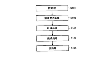
- FIG. 2 is a flowchart of the coating film manufacturing method in the embodiment of the present invention. First, with reference to these FIG. 1 and FIG. 2, the structure of the coating film manufacturing apparatus in this Embodiment and the flow of the coating film manufacturing method are demonstrated.
- a coating film manufacturing apparatus 1 includes a coating apparatus 2 as a solution coating section, a transport path 8, a heating and drying apparatus 10A, and a baking apparatus 4 as a coating film deposition section. And mainly.
- the coating film manufacturing apparatus 1 is installed in a factory or the like as a liquid crystal panel manufacturing line.
- the coating apparatus 2 is an apparatus for applying a solution containing a coating film material to the substrate 100.
- a solution containing a coating film material for example, polyimide is used as the alignment film material that is a coating film material, and a polyimide solution obtained by diluting polyimide with a highly volatile solvent is applied to the substrate 100 using the coating apparatus 2.
- the substrate 100 for example, a glass substrate is used.
- the coating device 2 for example, an inkjet coating device is used, and the above-described polyimide solution corresponds to a coating surface by being ejected in a dot array onto the substrate 100 placed on a stage (not shown). A polyimide solution is attached to the upper surface of the substrate 100.
- the transport path 8 is a part for transporting the substrate 100 and is defined by a transport mechanism described later.
- the conveyance path 8 includes a conveyance unit 11 for conveying the substrate 100 from the coating apparatus 2 toward the baking apparatus 4, and the heating and drying apparatus 10 ⁇ / b> A corresponds to the conveyance unit 11 in the conveyance path 8 described above. It is installed in the part.
- the heat drying apparatus 10A is an apparatus for drying the solution applied to the substrate 100, and heat treatment is used for drying the solution.
- the solvent or the like contained in the solution is mainly volatilized, and the temperature condition is controlled so that the peak value of the temperature of the solution is, for example, about 60 ° C. to 100 ° C.
- the details of the heat drying apparatus 10A will be described later.
- the baking apparatus 4 is an apparatus for forming a coating film on the substrate 100 by curing the solution applied to the substrate 100.
- heat treatment is used, and as the baking apparatus 4, for example, a baking furnace or the like is used.
- the coating film material is mainly cured, and the temperature condition is, for example, about 180 ° C. to 250 ° C.
- the coating film manufacturing apparatus 1 includes a first robot arm as a transport mechanism (not shown), and the first robot arm holds the substrate 100 before application of the solution transported on the transport path 8. This is carried into the coating apparatus 2, and the substrate 100 coated with the solution is held by the coating apparatus 2, and is unloaded from the coating apparatus 2 and returned onto the conveyance path 8.
- the movement of the substrate 100 by the first robot arm is indicated by an arrow 5.
- the coating film manufacturing apparatus 1 includes a second robot arm as a transfer mechanism (not shown), and the second robot arm holds the substrate 100 after the drying process transferred on the transfer path 8. Then, the substrate 100 is carried into the baking apparatus 4, and the substrate 100 after the baking process is carried out by the baking apparatus 4 is held and unloaded from the baking apparatus 4 and returned onto the transport path 8. In FIG. 1, the movement of the substrate 100 by the second robot arm is indicated by an arrow 7.
- the coating film manufacturing apparatus 1 includes a control unit (not shown) that synchronously controls operations of various apparatuses such as the coating apparatus 2, the baking apparatus 4, the conveyance path 8, and the first and second robot arms described above. By controlling the operation of each of the above devices by the control unit, the coating film manufacturing apparatus 1 is managed so that the coating film is formed on the substrate 100 with high production efficiency.
- a control unit (not shown) that synchronously controls operations of various apparatuses such as the coating apparatus 2, the baking apparatus 4, the conveyance path 8, and the first and second robot arms described above.
- pre-processing represented by cleaning processing or surface modification processing of the substrate 100 is performed.
- the substrate 100 after the pretreatment is introduced into the coating film manufacturing apparatus 1 in the above-described embodiment, is placed on the transport path 8, and is sequentially transported on the transport path 8.
- the substrate 100 transported by the transport path 8 is first carried into the coating apparatus 2 by the first robot arm described above, and a solution coating process (step S102) is performed in the coating apparatus 2.
- the substrate 100 after the solution coating process is performed is unloaded from the coating apparatus 2 by the first robot arm and placed on the transport unit 11 of the transport path 8.
- the substrate 100 that has been subjected to the solution coating process and placed on the transport unit 11 of the transport path 8 corresponds to the transport unit 11 by a transport mechanism that will be described later with the upper surface on which the solution is applied facing upward. It is transported on the partial transport path 8 and introduced into the heating / drying apparatus 10A, and a drying process (step S103) is performed in the heating / drying apparatus 10A. The substrate 100 after the drying process is performed is led out from the heating and drying apparatus 10A by the transport mechanism.
- the substrate 100 that has been subjected to the drying process is then carried into the baking apparatus 4 by the second robot arm described above, and the baking process (step S104) is performed in the baking apparatus 4.
- the substrate 100 after the baking process is carried out from the baking apparatus 4 by the second robot arm and placed on the transfer path 8.
- step S105 post-processing represented by rubbing processing or the like is performed on the substrate 100 derived from the coating film manufacturing apparatus 1.
- FIG. 3 to 5 are a schematic perspective view, a schematic plan view, and a schematic side view, respectively, of the heating and drying apparatus in the present embodiment.
- the heat drying apparatus in this Embodiment is demonstrated.
- the thing which utilizes a conveyor as a conveyance mechanism and utilizes radiant heat exclusively as a heating source is each employ
- the heating / drying apparatus 10 ⁇ / b> A mainly includes a conveyance path 8 corresponding to the conveyance unit 11, a conveyance roller 12, and a heating source 21.
- the transport roller 12 defines a transport path 8 through which the substrate 100 is transported, and is arranged below the transport path 8 along the transport direction of the substrate 100 (the direction of arrow A in the figure).
- the heating source 21 is composed of, for example, a plate-like heater extending in a direction orthogonal to the conveyance direction of the substrate 100, and is adjacent to the predetermined position of the conveyance path 8 defined by the conveyance roller 12 when viewed in plan.
- a plurality of rollers are arranged below the conveyance path 8 so as to be positioned between the rollers 12.
- positioned corresponds to the heat drying process area
- the transport roller 12 includes a roller portion 13 that extends along a direction orthogonal to the transport direction of the substrate 100 and a shaft portion 14 that pivotally supports the roller portion 13.
- the transport roller 12 transports the supported substrate 100 in the direction of arrow A in the figure while supporting the lower surface, which is the non-coating surface of the substrate 100, by rotating the shaft portion 14 by a drive mechanism (not shown).
- the heating source 21 is for drying the solution 102 by applying heat to the solution 102 applied to the substrate 100. More specifically, the solution 102 applied to the substrate 100 is heated through the substrate 100 and dried by the substrate 100 being heated by the radiant heat of the heating source 21.
- the heating source 21 has an amount of solution so that a heat amount that can sufficiently volatilize a solvent or the like contained in the solution 102 applied to the substrate 100 is given to the solution 102.
- the set temperature, installation position, size, and the like are appropriately optimized according to the thickness of the substrate, the conveyance speed of the substrate, and the like.
- heat is applied to the solution 102 applied to the substrate 100 that moves on the transport path 8 along the transport direction using the heating source 21.
- the drying treatment of the solution 102 applied to the substrate 100 is performed in the heat drying treatment region 20. That is, while the substrate 100 is being transported from the coating device 2 to the baking device 4, the substrate 102 is transported by the transport roller 12, and at the same time, the solution 102 applied to the substrate 100 can be dried. Therefore, not only can the substrate 100 be continuously dried, but also the installation space can be reduced.
- the substrate 100 transported on the transport path 8 sequentially passes through the heat drying treatment region 20 from the front end portion to the rear end portion along the transport direction. Is configured to do. Therefore, it is possible to perform heat treatment under uniform conditions on each part of the substrate 100 along the conveyance direction of the substrate 100, and as a result, uniformly over the entire area of the solution 102 applied to the substrate 100. It becomes possible to carry out a drying process.
- the coating is applied to the substrate while preventing an increase in installation space. Since it is possible to dry the solution continuously in a short time with high processing efficiency, not only can the coating film be formed with high production efficiency, but also the installation cost and running cost are relatively low. Furthermore, since it becomes possible to perform the drying process uniformly over the entire area of the solution applied to the substrate, it is possible to suppress the occurrence of unevenness in the thickness of the formed coating film. . These effects are significant when a coating film is formed on a larger substrate, and are particularly effective in the manufacture of liquid crystal panels and the like that have recently become increasingly large.
- the photo-alignment in which the alignment regulating force is changed by light irradiation as the coating film material by adopting the above-described heating and drying apparatus for manufacturing the coating film and the coating film manufacturing apparatus and the coating film manufacturing method provided with the same.
- the process can be performed continuously in a short time as described above. Contamination by organic components existing in the surrounding environment and exposure to external light existing in the surrounding environment can be greatly suppressed as compared to the conventional case. Therefore, it is possible to greatly reduce the deterioration of the reliability of the alignment film and the deterioration of display quality (burn-in, display unevenness, etc.) as compared with the conventional case.
- the kind of the photo-alignment film material whose alignment regulating force changes by the above-described light irradiation is not particularly limited, and examples thereof include a resin containing a photosensitive group. More specifically, a 4-chalcone group (see the following chemical formula (1)), a 4′-chalcone group (see the following chemical formula (2)), a coumarin group (see the following chemical formula (3)), a cinnamoyl group (the following chemical formula)
- a polyimide containing a photosensitive group such as (see (4)) is suitable.
- the photosensitive group causes a crosslinking reaction (including a dimerization reaction), an isomerization reaction, a photoreorientation, and the like by light irradiation. According to these, the pretilt is compared with a photodegradable photoalignment film material. The variation in corners can be effectively reduced.
- the photosensitive group includes those having a structure in which a substituent is bonded to a benzene ring represented by the following chemical formulas (1) to (4).
- a cinnamate group (C 6 H 5 —CH ⁇ CH—COO—) in which an oxygen atom is further bonded to a carbonyl group in the cinnamoyl group has an advantage that it is easier to synthesize than other photosensitive groups. If a polyimide containing a cinnamate group is used as the photo-alignment film material, an effect of facilitating the production can be obtained.
- FIG. 6 is a schematic side view of a heat drying apparatus according to a first modification based on the present embodiment. Next, with reference to this FIG. 6, the heat drying apparatus which concerns on the 1st modification based on this Embodiment is demonstrated.
- the heating / drying apparatus 10B according to the first modification is different from the heating / drying apparatus 10A in the present embodiment described above in the installation position of the heating source 21.
- the heating source 21 formed of a plate-like heater is disposed above the conveyance path 8, and is thereby conveyed on the conveyance path 8.
- the solution 102 is configured to be directly heated by the radiant heat of the heating source 21 from the upper surface side of the substrate 100.
- the heating and drying apparatus 10B according to the first modification described above is used, the same effects as those obtained when the heating and drying apparatus 10A according to the present embodiment described above can be obtained. Furthermore, by using the heating and drying apparatus 10B according to the first modified example, the solution 102 applied to the substrate 100 can be more efficiently heated, which can save space and improve production efficiency. It will be further planned.
- FIG. 7 is a schematic side view of a heat drying apparatus according to a second modification based on the present embodiment. Next, with reference to this FIG. 7, the heating-drying apparatus which concerns on the 2nd modification based on this Embodiment is demonstrated.
- the heating / drying apparatus 10 ⁇ / b> C according to the second modification is different from the heating / drying apparatus 10 ⁇ / b> B according to the first modification described above in the configuration in the vicinity of the heating source 21.
- the heating and drying apparatus 10 ⁇ / b> C according to the second modification includes a chamber 32 that covers a part of the conveyance path 8 in addition to the heating source 21.
- the chamber 32 is installed so as to surround the heating source 21 disposed above the conveyance path 8 in addition to a part of the conveyance path 8 described above.
- the region where the chamber 32 is installed corresponds to the heat drying treatment region 20.
- the same effect as that obtained when the heating and drying apparatus 10B according to the first modification described above is obtained can be obtained. Furthermore, since the heat drying apparatus 10C according to the second modified example can suppress the heat of the heating source 21 being released to the outside by the chamber 32, it can be more efficiently applied to the substrate 100. The solution 102 that is present can be heated, and space saving and improvement in production efficiency can be further achieved.
- FIG. 8 to 10 are a schematic perspective view, a schematic plan view, and a schematic side view, respectively, of a heat drying apparatus according to a third modification based on the present embodiment.
- the heat drying apparatus which concerns on the 3rd modification based on this Embodiment is demonstrated.
- the heating / drying apparatus 10 ⁇ / b> D according to the third modification is different in the size and number of the heating sources 21 compared to the heating / drying apparatus 10 ⁇ / b> A according to the present embodiment described above. .
- the heating source 21 including a large plate heater is viewed in plan at a predetermined position of the conveyance path 8 defined by the conveyance roller 12. In this case, one is disposed below the conveyance path 8 so as to overlap some of the conveyance rollers 12.
- positioned corresponds to the heat drying process area
- the heating and drying apparatus 10D in the heating and drying apparatus 10D according to the third modified example, at least a part of the conveyance roller 12 located above the heating source 21 (that is, the conveyance roller 12 located in the heating and drying treatment region 20).
- the member formed using quartz as a material Quartz has a relatively high infrared transmittance, and can sufficiently transmit infrared rays emitted from the heating source 21. Therefore, by forming a part of the transport roller 12 with quartz, Radiant heat can be applied to the substrate 100 more efficiently, and it is possible to suppress the heating of the substrate 100 from being interrupted by the transport roller 12.
- quartz has a thermal conductivity that is closer to the thermal conductivity of the atmosphere (for example, nitrogen gas that is an inert gas) in the heat-drying treatment region 20, so that efficient heating can be performed also from this viewpoint. it can.
- part or all of the shaft portion 14 may be formed of quartz, or part or all of the roller portion 13 may be formed of quartz. In any case, it is preferable to configure the transport roller 12 using quartz as much as possible within a range that does not hinder the transport of the substrate 100 by the transport roller 12.
- the heating / drying apparatus 10D according to the third modification described above is used, the same effects as those obtained when the heating / drying apparatus 10A according to the present embodiment described above can be obtained. Furthermore, by using the heating and drying apparatus 10D according to the third modified example, the solution 102 applied to the substrate 100 can be more efficiently heated, which can save space and improve production efficiency. It will be further planned.
- FIG. 11 to FIG. 13 are a schematic perspective view, a schematic plan view, and a schematic side view, respectively, of a heating and drying apparatus according to a fourth modification based on the present embodiment.
- a heating and drying apparatus according to a fourth modification based on the present embodiment.
- the heat drying apparatus which concerns on the 4th modification based on this Embodiment is demonstrated.
- a levitation type conveying apparatus is used as the conveying mechanism, and an apparatus that exclusively uses convection heat as the heating source is employed.
- the heating and drying apparatus 10E includes a transport path 8 corresponding to the transport unit 11, a transport stage 15, guide rails 17A and 17B, and sliders 18A and 18B. And mainly.
- the transport stage 15 defines a transport path 8 through which the substrate 100 is transported, and extends below the transport path 8 along the transport direction of the substrate 100 (the direction of arrow A in the figure).
- a large number of holes 16 are provided on the upper surface of the transfer stage 15, and each of the large number of holes 16 sucks a gas such as a jet hole 16 a for jetting a gas such as compressed air or a jet of compressed air or the like. It is comprised by either of the suction holes 16b (refer FIG. 12 and FIG. 13).
- the ejection holes 16 a are for floating the substrate 100 on the transfer stage 15 by blowing a gas such as compressed air to the lower surface, which is a non-coating surface of the substrate 100, and the suction holes 16 b are the lower surfaces of the substrate 100.
- the substrate 100 can be smoothly moved by immediately sucking a gas such as compressed air blown onto the substrate. From this point of view, the ejection holes 16a and the suction holes 16b are preferably provided alternately as shown in FIGS.
- the guide rails 17A and 17B are installed on both sides of the transport stage 15 so as to extend along the transport direction of the substrate 100, and sliders 18A and 18B are respectively disposed on the guide rails 17A and 17B. It is attached so as to be movable along the conveyance direction 100.
- Each of the sliders 18 ⁇ / b> A and 18 ⁇ / b> B is provided with holding portions 19 ⁇ / b> A and 19 ⁇ / b> B that can hold end portions in a direction orthogonal to the conveyance direction of the substrate 100.
- the holding portions 19A and 19B may be any as long as they can hold the end portion of the substrate 100.
- a holding mechanism that sucks and holds the end portion of the substrate 100 with a negative pressure, A holding mechanism or the like that can clamp the end portion can be used.
- the sliders 18A and 18B are driven by a driving mechanism (not shown) to convey the held substrate 100 in the direction of arrow A in the figure.
- the transport stage 15 has a heat drying treatment region 20 at a predetermined position in the transport direction of the substrate 100, and a portion of the ejection hole 16 a corresponding to the heat drying treatment region 20 (spout contained in the region 22 shown in the figure).
- a pressurized gas such as heated compressed air is ejected from the holes 16a).
- the heated pressurized gas such as compressed air is heated to a predetermined temperature by passing a gas such as compressed air through a heat source (not shown), and blown onto the lower surface of the substrate 100 to cause the substrate 100 to flow.
- the substrate 102 is heated by its convection heat, and the solution 102 (see FIGS. 12 and 13) applied to the substrate 100 is heated and dried.
- the number, size, pitch, installation position, shape, etc. of the ejection holes 16a through which the heated gas is ejected, the set temperature of the heated gas, etc. are sufficient for the solvent contained in the solution 102 applied to the substrate 100.
- the amount of heat that can be volatilized is applied to the solution 102, and is optimized as appropriate according to the amount of the solution, the thickness of the substrate, the conveyance speed of the substrate, and the like.
- the gas type of the heated gas to be sprayed is not particularly limited, and may be an inert gas or the like instead of compressed air or the like.
- the heating / drying apparatus 10E according to the fourth modified example described above is used, the same effect as that obtained when the heating / drying apparatus 10A according to the present embodiment described above can be obtained. Furthermore, by using the heating and drying apparatus 10E according to the fourth modification, the substrate 100 can be transported in a substantially non-contact state, so that the problem that the substrate 100 is damaged can be solved. It becomes possible.
- a conveyor is configured as a transport mechanism, and a combination of a heating mechanism that uses radiant heat exclusively, and a levitation transport device as a heating mechanism is used as a heating source.
- a conveyor may be configured as a transport mechanism, and a combination that uses convection heat exclusively as a heating source, or a levitation type transport device may be configured as a transport mechanism and a combination that uses radiant heat exclusively as a heating source. May be.
- a heating source that uses both convection heat and radiant heat may be used, or a heating source that exclusively uses radiant heat may be used in combination with a heating source that exclusively uses convection heat. .
- an alignment film manufacturing apparatus used in the alignment film manufacturing process included in the liquid crystal panel manufacturing process, and a heating and drying apparatus included therein and The case where the present invention is applied to the method of manufacturing the alignment film has been described as an example.
- the coating film manufacturing apparatus used in the manufacturing process of other functional films such as a resist film, and the heating provided in the apparatus Of course, it is also possible to apply the present invention to a drying apparatus and a method for producing an alignment film.
Landscapes
- Engineering & Computer Science (AREA)
- Mechanical Engineering (AREA)
- General Engineering & Computer Science (AREA)
- Life Sciences & Earth Sciences (AREA)
- Microbiology (AREA)
- Drying Of Solid Materials (AREA)
- Coating Apparatus (AREA)
Abstract
加熱乾燥装置(10A)は、塗布膜材料を含む溶液が上面に塗布されている基板(100)を当該上面が鉛直上方を向いた姿勢を維持しつつ搬送する搬送ローラ(12)と、搬送ローラ(12)によって規定される搬送路(8)上を移動している基板(100)の上面に塗布されている溶液に対して熱を付与することにより、当該溶液の乾燥処理を行なう加熱源(21)とを備える。
Description
本発明は、塗布膜材料を含む溶液を基板に塗布し、塗布した溶液を乾燥および硬化させることで基板に塗布膜を成膜する塗布膜製造装置およびこれに具備される塗布膜製造用加熱乾燥装置ならびに塗布膜製造方法に関する。
液晶パネルや半導体装置等の製造工程の一つに、配向膜やレジスト膜等の機能性膜を塗布膜製造装置を利用して基板に形成する工程がある。塗布膜製造技術は、塗布膜材料を含む溶液を基板に塗布し、塗布した溶液を乾燥および硬化させることで基板に塗布膜を成膜する技術である。
一般に、硬化前の塗布膜材料である機能性膜の原液は、高い粘性を有しているため、通常は、揮発性の高い溶剤等を添加することで原液を希釈化し、希釈化後の溶液が基板に塗布される。溶液が塗布された基板には、その後加熱処理が段階的に施され、その第1段階として溶剤等の乾燥処理が実施され、その第2段階として塗布膜材料の硬化処理が実施される。なお、基板への溶液の塗布には、インクジェット塗布装置等が利用され、溶液の乾燥にはホットプレートや高温槽が利用され、溶液の硬化には、焼成炉等が利用されることが一般的である。
上述した乾燥処理に使用される塗布膜製造用加熱乾燥装置(以下、単に加熱乾燥装置とも称する)としては、たとえば特開2006-7029号公報(特許文献1)や特開2006-130374号公報(特許文献2)、特開2006-21138号公報(特許文献3)等に開示のものがある。
上記特開2006-7029号公報に開示された加熱乾燥装置は、溶液が上面に塗布されている基板をステージ上に載置し、基板の上方にプレート状ヒータを配置することで専らその輻射熱を利用して溶液を加熱して乾燥させるものである。
上記特開2006-130374号公報に開示された加熱乾燥装置は、溶液が上面に塗布されている基板をヒータを具備したステージ上に載置し、ヒータの輻射熱を利用して基板を加熱することで基板を介して溶液を加熱して乾燥させるものである。
上記特開2006-21138号公報に開示された加熱乾燥装置は、溶液が上面に塗布されている基板をステージ上に載置し、基板の上方から加熱ガス等の気流を溶液に向けて吹き付けることで専らその対流熱を利用して溶液を加熱して乾燥させるものである。
しかしながら、上述した特開2006-7029号公報、特開2006-130374号公報および特開2006-21138号公報に開示される如くの加熱乾燥装置は、いずれも溶液が塗布されている基板をステージ上に固定的に載置して溶液の乾燥処理を行なうものであるため、連続した基板の処理には必ずしも適しておらず、生産効率が低下してしまう問題があった。
そのため、上述した如くの加熱乾燥装置を利用して生産効率の向上を図るためには、当該加熱乾燥装置を複数準備してこれら複数の加熱乾燥装置において同時並行的に乾燥処理が行なわれるようにする必要があるが、そのようにした場合には、加熱乾燥装置の設置コストおよびランニングコストが増大するばかりでなく、大きな設置スペースが必要になる問題も別途生じてしまう。特に、液晶パネルの製造工程等においては、近年、マザー基板の飛躍的な大型化が進んでおり、上述した設置スペースの問題は、非常に顕著なものとなってしまう。
また、上述した如くの加熱乾燥装置を利用した場合には、基板の上面に塗布されている加熱すべき溶液に熱分布が生じ易くなってしまうため、溶液を全域にわたって均等に加熱することが難しく、その結果、形成される塗布膜の厚み等にムラが生じてしまう問題も生じてしまう。
また、上述した如くの加熱乾燥装置を利用して、塗布膜材料として光照射により配向規制力が変化する光配向膜材料を使用して液晶パネルの配向膜を製造することとした場合には、以下の2つの問題が生じる。
第1の問題は、配向膜の形成時において、周辺環境に存する有機成分によって光配向膜材料が汚染され、その結果、配向膜の信頼性が低下して表示品位の悪化(焼き付きや表示ムラ等)が生じるおそれがあった。第2の問題は、配向膜の形成時において、周辺環境に存する外光の影響により光配向膜材料が感光し、その結果、配向膜の信頼性が低下して上述した表示品位の悪化が生じるおそれがあった。そのため、従来においては、配向膜の製造に使用するラインにケミカルフィルタを設置して有機成分を除去したり、遮光部を設けて外光の入射を防止したりすることでその対策が採られていた。
ここで、これらの問題は、いずれも配向膜の製造に要する処理時間が長ければ長いほどより顕著に生じてしまう問題であり、当該処理がより効率的に短時間で実施できれば、当該問題の改善にもつながることになる。
したがって、本発明は、上述した問題点を解決すべくなされたものであり、設置スペースの増大を防止しつつ基板に塗布されている溶液を均等に高い処理効率で連続的に短時間に乾燥処理することが可能な塗布膜製造用加熱乾燥装置およびこれを備えた塗布膜製造装置ならびに塗布膜製造方法を提供することを目的とする。
本発明に基づく塗布膜製造用加熱乾燥装置は、塗布膜材料を含む溶液が上面に塗布されている基板を当該上面が鉛直上方を向いた姿勢を維持しつつ搬送する搬送機構と、上記搬送機構によって規定される搬送路上を移動している基板の上面に塗布されている溶液に対して熱を付与することにより、当該溶液の乾燥処理を行なう加熱源とを備えている。
上記本発明に基づく塗布膜製造用加熱乾燥装置にあっては、上記加熱源が、輻射熱を利用して溶液を加熱するものであることが好ましい。その場合には、上記搬送機構が、溶液が上面に塗布されている基板の下面を支持しつつ、支持した基板を搬送するコンベヤにて構成されていてもよいし、溶液が上面に塗布されている基板の下面に向けて気体を吹き付けることで基板を浮揚させつつ、浮揚させた基板を搬送する浮揚式搬送装置にて構成されていてもよい。ここで、特に搬送機構がコンベヤにて構成されている場合には、当該コンベヤの少なくとも一部が、石英にて構成されていることが好ましい。
上記本発明に基づく塗布膜製造用加熱乾燥装置にあっては、上記加熱源が、対流熱を利用して溶液を加熱するものであることが好ましい。その場合には、上記搬送機構が、溶液が上面に塗布されている基板の下面を支持しつつ、支持した基板を搬送するコンベヤにて構成されていてもよいし、溶液が上面に塗布されている基板の下面に向けて気体を吹き付けることで基板を浮揚させつつ、浮揚させた基板を搬送する浮揚式搬送装置にて構成されていてもよい。ここで、特に搬送機構が浮揚式搬送装置にて構成されている場合には、当該浮揚式搬送装置が、上記加熱源によって溶液の乾燥処理が行なわれる加熱乾燥処理領域に対応する部分において基板の下面に向けて加熱ガスを吹き付けるように構成されていることが好ましく、これにより基板を浮揚させて搬送しつつ溶液の乾燥処理が行なわれることが好ましい。
上記本発明基づく塗布膜製造用加熱乾燥装置にあっては、上記塗布膜材料が、光照射により配向規制力が変化する光配向膜材料であることが好ましい。その場合には、上記光配向膜材料が、4-カルコン基、4’-カルコン基、クマリン基およびシンナモイル基からなる群より選択される少なくとも1つの感光性基を含む材料であることがさらに好ましい。
本発明に基づく塗布膜製造装置は、塗布膜材料を含む溶液を基板に塗布する溶液塗布部と、基板に塗布されている溶液を硬化させることで基板に塗布膜を成膜する塗布膜成膜部と、上記溶液塗布部から上記塗布膜成膜部に向けて基板を搬送するための搬送部とを備えており、上述したいずれかの塗布膜製造用加熱乾燥装置が、上記搬送部に設けられてなるものである。
本発明に基づく塗布膜製造方法は、塗布膜材料を含む溶液を基板に塗布し、塗布した溶液を硬化させることで基板に塗布膜を成膜するものであって、溶液塗布後であって塗布膜成膜前に、溶液が上面に塗布されている基板を搬送機構を用いて当該上面が鉛直上方を向いた姿勢を維持しつつ搬送するとともに、上記搬送機構によって規定される搬送路上を移動している基板の上面に塗布されている溶液に対して加熱源を用いて熱を付与することにより、当該溶液の乾燥処理を行なうことを特徴としている。
上記本発明基づく塗布膜製造方法にあっては、上記塗布膜材料が、光照射により配向規制力が変化する光配向膜材料であることが好ましい。その場合には、上記光配向膜材料が、4-カルコン基、4’-カルコン基、クマリン基およびシンナモイル基からなる群より選択される少なくとも1つの感光性基を含む材料であることがさらに好ましい。
本発明によれば、設置スペースの増大を防止しつつ基板に塗布されている溶液を均等に高い処理効率で連続的に短時間に乾燥処理することが可能な塗布膜製造用加熱乾燥装置およびこれを備えた塗布膜製造装置ならびに塗布膜製造方法とすることができる。
以下、本発明の実施の形態について、図を参照して詳細に説明する。以下に示す実施の形態においては、液晶パネルの製造工程に含まれる配向膜の製造工程において使用される配向膜の製造装置およびこれに具備される加熱乾燥装置ならびに配向膜の製造方法に本発明を適用した場合を例示して説明を行なう。なお、以下に示す実施の形態においては、同一または共通する部分について図中同一の符号を付し、その説明は個別には繰り返さない。
図1は、本発明の実施の形態における塗布膜製造装置の概念図である。また、図2は、本発明の実施の形態における塗布膜製造方法のフロー図である。まず、これら図1および図2を参照して、本実施の形態における塗布膜製造装置の構成および塗布膜製造方法のフローについて説明する。
図1に示すように、本実施の形態における塗布膜製造装置1は、溶液塗布部としての塗布装置2と、搬送路8と、加熱乾燥装置10Aと、塗布膜成膜部としての焼成装置4とを主として備えている。塗布膜製造装置1は、液晶パネルの製造ラインとして工場等に設置されるものである。
塗布装置2は、基板100に塗布膜材料を含む溶液を塗布するための装置である。塗布膜材料である配向膜材料としては、たとえばポリイミドが使用され、ポリイミドを揮発性の高い溶剤で希釈したポリイミド溶液が、塗布装置2を用いて基板100に塗布される。基板100としては、たとえばガラス基板が使用される。塗布装置2としては、たとえばインクジェット塗布装置が利用され、上述したポリイミド溶液がステージ(不図示)上に載置された基板100に対して点列状に吐出されることにより、塗布面に相当する基板100の上面にポリイミド溶液が付着される。
搬送路8は、基板100を搬送するための部位であり、後述する搬送機構によって規定されている。搬送路8は、塗布装置2から焼成装置4に向けて基板100を搬送するための搬送部11を含んでおり、加熱乾燥装置10Aは、上述した搬送路8のうちの搬送部11に該当する部分に設置されている。
加熱乾燥装置10Aは、基板100に塗布されている溶液を乾燥させるための装置であり、この溶液の乾燥には、加熱処理が利用される。ここで、加熱乾燥装置10Aにおいては、主として溶液に含まれる溶剤等が揮発され、その温度条件は、溶液の温度のピーク値がたとえば60℃~100℃程度となるように制御される。なお、加熱乾燥装置10Aの詳細については、後述することとする。
焼成装置4は、基板100に塗布されている溶液を硬化させることで基板100に塗布膜を成膜するための装置である。溶液の硬化には、加熱処理が利用され、焼成装置4としては、たとえば焼成炉等が利用される。なお、焼成装置4においては、主として塗布膜材料が硬化され、その温度条件は、たとえば180℃~250℃程度である。
塗布膜製造装置1は、図示しない搬送機構としての第1のロボットアームを具備しており、当該第1のロボットアームは、搬送路8上を搬送される溶液塗布前の基板100を保持してこれを塗布装置2に搬入するとともに、塗布装置2にて溶液が塗布された基板100を保持してこれを塗布装置2から搬出して搬送路8上に復帰させる。図1中においては、当該第1のロボットアームによる基板100の動きを矢印5にて示している。
また、塗布膜製造装置1は、図示しない搬送機構としての第2のロボットアームを具備しており、当該第2のロボットアームは、搬送路8上を搬送される乾燥処理後の基板100を保持してこれを焼成装置4に搬入するとともに、焼成装置4にて焼成処理が実施された後の基板100を保持してこれを焼成装置4から搬出して搬送路8上に復帰させる。図1中においては、当該第2のロボットアームによる基板100の動きを矢印7にて示している。
塗布膜製造装置1は、上述した塗布装置2や焼成装置4、搬送路8、第1および第2のロボットアーム等の各種装置の動作を同期的に制御する図示しない制御部を具備しており、当該制御部によって上記各装置の動作が制御されることにより、高い生産効率にて基板100に塗布膜が形成されるように塗布膜製造装置1が管理されている。
図2に示すように、本実施の形態における塗布膜製造方法にあっては、まず、基板100の洗浄処理や表面改質処理等に代表される前処理(ステップS101)が行なわれる。前処理が実施された後の基板100は、上述した本実施の形態における塗布膜製造装置1に導入され、搬送路8上に載置されて当該搬送路8上を順次搬送される。
搬送路8によって搬送される基板100は、まず、上述した第1のロボットアームによって塗布装置2に搬入され、当該塗布装置2において溶液塗布処理(ステップS102)が行なわれる。溶液塗布処理が実施された後の基板100は、第1のロボットアームによって塗布装置2から搬出されて搬送路8の搬送部11上に載置される。
溶液塗布処理が実施されて搬送路8の搬送部11上に載置された基板100は、溶液が塗布されている上面が上方を向いた姿勢のまま後述する搬送機構によって搬送部11に該当する部分の搬送路8上を搬送されて加熱乾燥装置10Aに導入され、当該加熱乾燥装置10Aにおいて乾燥処理(ステップS103)が行なわれる。乾燥処理が実施された後の基板100は、上記搬送機構によって加熱乾燥装置10Aから導出される。
乾燥処理が実施された基板100は、次に、上述した第2のロボットアームによって焼成装置4に搬入され、当該焼成装置4において焼成処理(ステップS104)が行われる。焼成処理が実施された後の基板100は、第2のロボットアームによって焼成装置4から搬出されて搬送路8上に載置される。
次に、塗布膜が成膜された基板100は、搬送路8上を順次搬送され、上述した本実施の形態における塗布膜製造装置1から導出される。本実施の形態における塗布膜製造方法にあっては、塗布膜製造装置1から導出された後の基板100にラビング処理等に代表される後処理(ステップS105)が行なわれる。
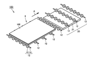
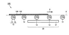
図3ないし図5は、本実施の形態における加熱乾燥装置のそれぞれ概略斜視図、概略平面図および概略側面図である。次に、これら図3ないし図5を参照して、本実施の形態における加熱乾燥装置について説明する。なお、本実施の形態における加熱乾燥装置においては、搬送機構としてコンベヤを、加熱源として専ら輻射熱を利用するものをそれぞれ採用している。
図3ないし図5に示すように、本実施の形態における加熱乾燥装置10Aは、搬送部11に該当する部分の搬送路8と、搬送ローラ12と、加熱源21とを主として備えている。搬送ローラ12は、基板100が搬送される搬送路8を規定しており、基板100の搬送方向(図中矢印A方向)に沿って搬送路8の下方に整列して配置されている。加熱源21は、たとえば基板100の搬送方向と直交する方向に延在するプレート状のヒータからなり、上記搬送ローラ12によって規定された搬送路8の所定位置において、平面視した場合に隣り合う搬送ローラ12の間に位置するように当該搬送路8の下方に複数配置されている。なお、加熱源21が配置された領域が、溶液102(図5参照)の乾燥を行なう加熱乾燥処理領域20に相当することになる。
搬送ローラ12は、基板100の搬送方向と直交する方向に沿って延在するローラ部13と、当該ローラ部13を軸支するシャフト部14とを含んでいる。搬送ローラ12は、図示しない駆動機構によってシャフト部14が回転駆動されることで、基板100の非塗布面である下面を支持しつつ、支持した基板100を図中矢印A方向に搬送する。
加熱源21は、基板100に塗布されている溶液102に対して熱を付与することで当該溶液102を乾燥させるためのものである。より詳細には、基板100に塗布されている溶液102は、加熱源21の輻射熱によって基板100が加熱されることで当該基板100を介して加熱されて乾燥する。ここで、加熱源21は、基板100に塗布されている溶液102に含まれる溶剤等を十分に揮発させることが可能な熱量が溶液102に対して付与されることとなるように、溶液の量や基板の厚み、基板の搬送速度等に応じてその設定温度や設置位置、大きさ等が適宜最適化される。
以上において説明した本実施の形態における加熱乾燥装置10Aにおいては、搬送路8上を搬送方向に沿って移動する基板100に塗布されている溶液102に対して加熱源21を用いて熱が付与されることになり、これにより基板100に塗布されている溶液102の乾燥処理が加熱乾燥処理領域20において行なわれることになる。すなわち、塗布装置2から焼成装置4に搬送される間において、搬送ローラ12によって基板100を搬送しつつ、これと同時に基板100に塗布されている溶液102の乾燥処理が行なえることになる。そのため、連続的に基板100を乾燥処理することが可能になるばかりでなく、設置スペースの狭小化も図られることになる。
また、上述した本実施の形態における加熱乾燥装置10Aにおいては、搬送路8上を搬送される基板100が、搬送方向に沿って前端部から後端部にかけて、順次、加熱乾燥処理領域20を通過するように構成されている。そのため、基板100の搬送方向に沿って基板100の各部に対して均一な条件の下に加熱処理を施すことが可能になり、その結果、基板100に塗布されている溶液102の全域にわたって均等に乾燥処理を実施することが可能になる。
したがって、上述した本実施の形態における塗布膜製造用加熱乾燥装置およびこれを備えた塗布膜製造装置ならびに塗布膜製造方法を採用することにより、設置スペースの増大を防止しつつ基板に塗布されている溶液を高い処理効率で連続的に短時間に乾燥処理することが可能になるため、高い生産効率にて塗布膜の形成を行なうことができるばかりでなく、設置コストやランニングコストを比較的安価に抑制することが可能になり、さらには、基板に塗布されている溶液の全域にわたって均等に乾燥処理を行なうことが可能になるため、形成される塗布膜の厚み等にムラが生じることも抑制できる。これらの効果は、より大きな基板に塗布膜を形成する場合にその意義が大きく、特に近年その大型化が顕著である液晶パネル等の製造において高い効果を発揮する。
また、上述した本実施の形態における塗布膜製造用加熱乾燥装置およびこれを備えた塗布膜製造装置ならびに塗布膜製造方法を採用して、塗布膜材料として光照射により配向規制力が変化する光配向膜材料を使用して液晶パネルの配向膜を製造することとした場合には、上述しように連続的に短時間で処理を行なうことが可能になるため、配向膜の形成時において光配向膜材料が周辺環境に存する有機成分によって汚染されることや周辺環境に存する外光によって感光されてしまうことが従来に比して大幅に抑制できる。したがって、配向膜の信頼性が低下して表示品位の悪化(焼き付きや表示ムラ等)が生じることを従来に比して大幅に低減することが可能になる。
ここで、上述した光照射により配向規制力が変化する光配向膜材料としては、特にその種類が限定されず、たとえば感光性基を含む樹脂等が挙げられる。より具体的には、4-カルコン基(下記化学式(1)参照)や、4’-カルコン基(下記化学式(2)参照)、クマリン基(下記化学式(3)参照)、シンナモイル基(下記化学式(4)参照)等の感光性基を含むポリイミド等が好適である。上記感光性基は、光照射により架橋反応(二量化反応を含む)、異性化反応、光再配向等を生じるものであり、これらによれば、光分解型の光配向膜材料に比べてプレチルト角のばらつきを効果的に小さくすることができる。
なお、上記感光性基には、下記化学式(1)~(4)に示されるベンゼン環に置換基が結合した構造のものも含まれる。また、シンナモイル基におけるカルボニル基にさらに酸素原子が結合したシンナメート基(C6H5-CH=CH-COO-)は、他の光感光性基に比較して合成し易いという利点を有しており、光配向膜材料としてシンナメート基を含むポリイミドを利用すれば、その製造が容易になる効果も得られる。
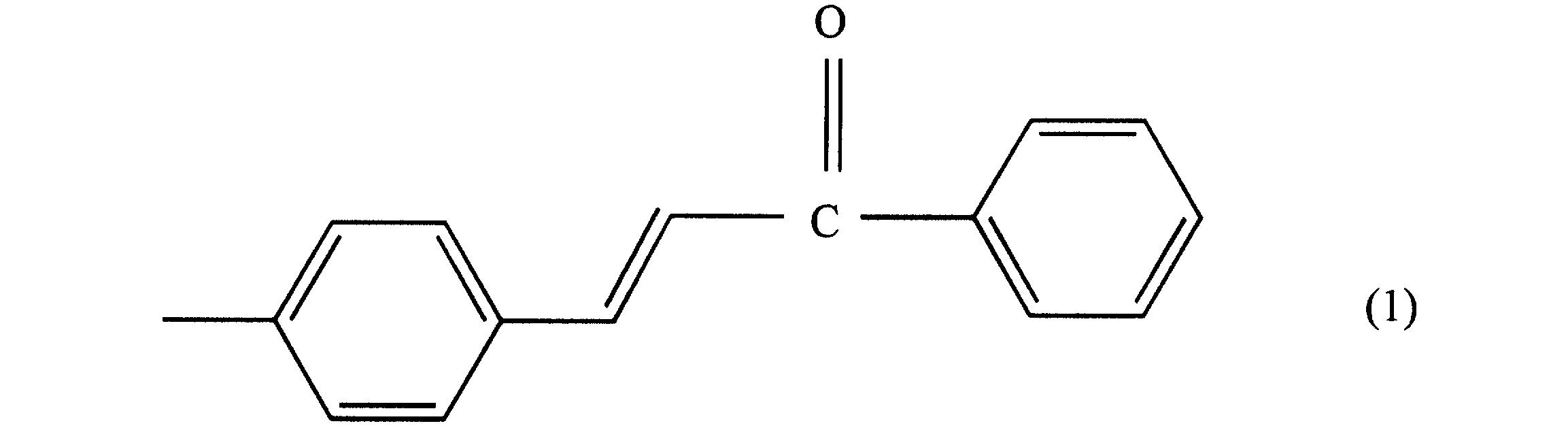
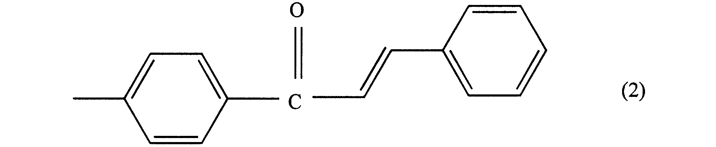
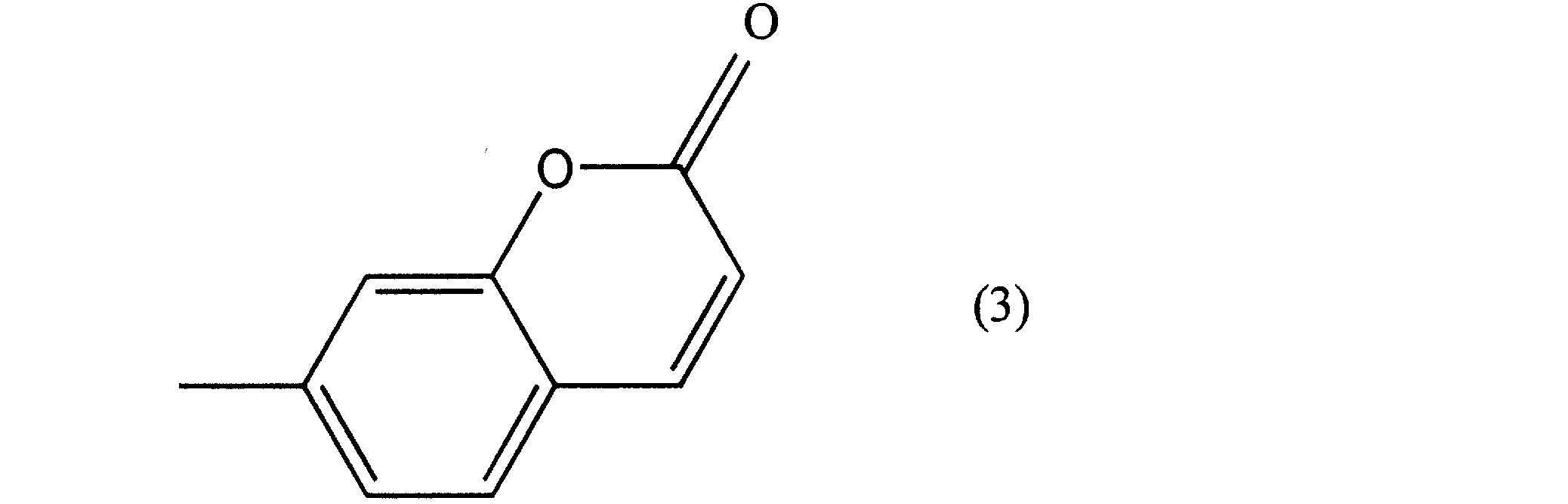

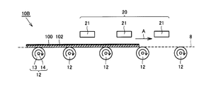
図6は、本実施の形態に基づく第1変形例に係る加熱乾燥装置の概略側面図である。次に、この図6を参照して、本実施の形態に基づく第1変形例に係る加熱乾燥装置について説明する。
図6に示すように、本第1変形例に係る加熱乾燥装置10Bは、上述した本実施の形態における加熱乾燥装置10Aに比べて加熱源21の設置位置において相違している。具体的には、本第1変形例に係る加熱乾燥装置10Bにおいては、プレート状のヒータからなる加熱源21が搬送路8の上方に配置されており、これにより搬送路8上を搬送される基板100の上面側から溶液102が加熱源21の輻射熱によって直接加熱されるように構成されている。
以上において説明した本第1変形例に係る加熱乾燥装置10Bとした場合にも、上述した本実施の形態における加熱乾燥装置10Aとした場合と同様の効果を得ることができる。さらには、本第1変形例に係る加熱乾燥装置10Bとすることにより、より効率的に基板100に塗布されている溶液102を加熱することが可能になり、省スペース化や生産効率の向上がさらに図られることになる。
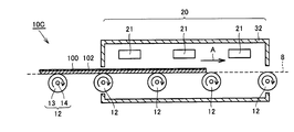
図7は、本実施の形態に基づく第2変形例に係る加熱乾燥装置の概略側面図である。次に、この図7を参照して、本実施の形態に基づく第2変形例に係る加熱乾燥装置について説明する。
図7に示すように、本第2変形例に係る加熱乾燥装置10Cは、上述した第1変形例に係る加熱乾燥装置10Bに比べて加熱源21の近傍の構成において相違している。具体的には、本第2変形例に係る加熱乾燥装置10Cは、加熱源21に加え、搬送路8の一部を覆うチャンバ32を備えている。チャンバ32は、上述した搬送路8の一部に加え、搬送路8の上方に配置された加熱源21をも取り囲むように設置されている。ここで、チャンバ32が設置された領域が、加熱乾燥処理領域20に相当することになる。
以上において説明した本第2変形例に係る加熱乾燥装置10Cとした場合にも、上述した第1変形例に係る加熱乾燥装置10Bとした場合と同様の効果を得ることができる。さらには、本第2変形例に係る加熱乾燥装置10Cとすることにより、チャンバ32によって加熱源21の熱が外部へと放出されることが抑制できるため、より効率的に基板100に塗布されている溶液102を加熱することが可能になり、省スペース化や生産効率の向上がさらに図られることになる。
図8ないし図10は、本実施の形態に基づく第3変形例に係る加熱乾燥装置のそれぞれ概略斜視図、概略平面図および概略側面図である。次に、これら図8ないし図10を参照して、本実施の形態に基づく第3変形例に係る加熱乾燥装置について説明する。
図8ないし図10に示すように、本第3変形例に係る加熱乾燥装置10Dは、上述した本実施の形態における加熱乾燥装置10Aに比べて加熱源21の大きさおよび数において相違している。具体的には、本第1変形例に係る加熱乾燥装置10Dにおいては、大型のプレート状のヒータからなる加熱源21が、搬送ローラ12によって規定された搬送路8の所定位置において、平面視した場合に一部の搬送ローラ12と重なるように当該搬送路8の下方に一つ配置されている。なお、加熱源21が配置された領域が、溶液102(図10参照)の乾燥を行なう加熱乾燥処理領域20に相当することになる。
ここで、第3変形例に係る加熱乾燥装置10Dにあっては、加熱源21の上方に位置する部分の搬送ローラ12(すなわち、加熱乾燥処理領域20に位置する搬送ローラ12)の少なくとも一部が、石英を材料として形成された部材にて構成されている。石英は、赤外線の透過率が比較的高く、加熱源21から発せられる赤外線を十分に透過することが可能であるため、搬送ローラ12の一部を石英にて構成することにより、加熱源21の輻射熱をより効率的に基板100に対して付与することが可能となり、搬送ローラ12によって基板100の加熱が遮られることが抑制可能になる。また、石英は、加熱乾燥処理領域20の雰囲気(たとえば不活性ガスである窒素ガス)の熱伝導率により近い熱伝導率を有しているため、当該観点からも効率的な加熱を行なうことができる。
なお、具体的には、シャフト部14の一部または全部を石英にて形成してもよいし、ローラ部13の一部または全部を石英にて形成してもよい。いずれの場合にも、搬送ローラ12による基板100の搬送に支障が出ない範囲で石英を可能な限り使用して搬送ローラ12を構成することが好ましい。
以上において説明した本第3変形例に係る加熱乾燥装置10Dとした場合にも、上述した本実施の形態における加熱乾燥装置10Aとした場合と同様の効果を得ることができる。さらには、本第3変形例に係る加熱乾燥装置10Dとすることにより、より効率的に基板100に塗布されている溶液102を加熱することが可能になり、省スペース化や生産効率の向上がさらに図られることになる。
図11ないし図13は、本実施の形態に基づく第4変形例に係る加熱乾燥装置のそれぞれ概略斜視図、概略平面図および概略側面図である。次に、これら図11ないし図13を参照して、本実施の形態に基づく第4変形例に係る加熱乾燥装置について説明する。なお、本第4変形例に係る加熱乾燥装置においては、搬送機構として浮揚式搬送装置を、加熱源として専ら対流熱を利用するものをそれぞれ採用している。
図11ないし図13に示すように、本第4変形例に係る加熱乾燥装置10Eは、搬送部11に該当する搬送路8と、搬送ステージ15と、ガイドレール17A,17Bと、スライダ18A,18Bとを主として備えている。搬送ステージ15は、基板100が搬送される搬送路8を規定しており、基板100の搬送方向(図中矢印A方向)に沿って搬送路8の下方において延在している。
搬送ステージ15の上面には、多数の孔16が設けられており、これら多数の孔16のそれぞれは、圧縮空気等の気体を噴出する噴出孔16aまたは噴出された圧縮空気等の気体を吸引する吸引孔16bのいずれかによって構成されている(図12および図13参照)。噴出孔16aは、基板100の非塗布面である下面に圧縮空気等の気体を吹き付けることにより、搬送ステージ15上において基板100を浮揚させるためのものであり、吸引孔16bは、基板100の下面に吹き付けられた圧縮空気等の気体を直ちに吸引することでスムーズな基板100の移動を実現されるためのものである。当該観点から、噴出孔16aおよび吸引孔16bは、図12および図13に示すように、交互に設けられていることが好ましい。
ガイドレール17A,17Bは、基板100の搬送方向に沿って延在するように搬送ステージ15の両脇に設置されており、当該ガイドレール17A,17Bの各々には、スライダ18A,18Bがそれぞれ基板100の搬送方向に沿って移動可能に取付けられている。スライダ18A,18Bの各々には、基板100の搬送方向と直交する方向の端部を保持可能な保持部19A,19Bがそれぞれ設けられている。
保持部19A,19Bとしては、基板100の上記端部を保持可能なものであればどのようなものでもよく、たとえば負圧により基板100の上記端部を吸着保持する保持機構や、基板100の上記端部を挟持可能な保持機構等が利用可能である。なお、スライダ18A,18Bは、図示しない駆動機構によって駆動されることにより、保持した基板100を図中矢印A方向に搬送する。
搬送ステージ15は、基板100の搬送方向の所定位置に加熱乾燥処理領域20を有しており、当該加熱乾燥処理領域20に該当する部分の噴出孔16a(図中に示す領域22に含まれる噴出孔16a)からは、加熱された圧縮空気等の加圧ガスが噴出される。この加熱された圧縮空気等の加圧ガスは、図示しない熱源に圧縮空気等の気体を通ずることで所定の温度にまで昇温されたものであり、基板100の下面に吹き付けられることにより基板100を浮揚させるとともに、基板100をその対流熱によって加熱して基板100に塗布されている溶液102(図12および図13参照)を加熱して乾燥させるものである。
ここで、加熱ガスを噴出する噴出孔16aの数や大きさ、ピッチ、設置位置、形状等および加熱ガスの設定温度等は、基板100に塗布されている溶液102に含まれる溶剤等を十分に揮発させることが可能な熱量が溶液102に対して付与されることとなるように、溶液の量や基板の厚み、基板の搬送速度等に応じて適宜最適化される。なお、吹き付けられる加熱ガスの気体種についても特に制限されるものではなく、圧縮空気等に代えて不活性ガス等としてもよい。
以上において説明した本第4変形例に係る加熱乾燥装置10Eとした場合にも、上述した本実施の形態における加熱乾燥装置10Aとした場合と同様の効果を得ることができる。さらには、本第4変形例に係る加熱乾燥装置10Eとすることにより、基板100を実質的に非接触の状態で搬送することが可能になるため、基板100が傷つくといった問題を解消することも可能になる。
上述した本発明の実施の形態ならびにその変形例においては、搬送機構としてコンベヤを、加熱源として専ら輻射熱を利用するものを組み合わせて構成した場合と、搬送機構として浮揚式搬送装置を、加熱源として専ら対流熱を利用するものを組み合わせて構成した場合とを例示して説明を行なったが、これらの組み合わせは、必要に応じて適宜変更することが可能である。すなわち、搬送機構としてコンベヤを、加熱源として専ら対流熱を利用するものを組み合わせて構成してもよいし、搬送機構として浮揚式搬送装置を、加熱源として専ら輻射熱を利用するものを組み合わせて構成してもよい。さらには、加熱源として対流熱および輻射熱の両方を利用するものを使用してもよいし、加熱源として専ら輻射熱を利用するものと専ら対流熱を利用するものとを組み合わせて使用してもよい。
また、上述した本発明の実施の形態およびその変形例においては、主として、搬送機構としてローラコンベヤを使用した場合を例示して説明を行なったが、この他にもコンベヤとしてはベルトコンベヤ等を利用することも可能である。
さらには、上述した本発明の実施の形態ならびにその変形例においては、液晶パネルの製造工程に含まれる配向膜の製造工程において使用される配向膜の製造装置およびこれに具備される加熱乾燥装置ならびに配向膜の製造方法に本発明を適用した場合を例示して説明を行なったが、レジスト膜等、他の機能性膜の製造工程において使用される塗布膜の製造装置およびこれに具備される加熱乾燥装置ならびに配向膜の製造方法に本発明を適用することも当然に可能である。
このように、今回開示した上記実施の形態はすべての点で例示であって、制限的なものではない。本発明の技術的範囲は請求の範囲によって画定され、また請求の範囲の記載と均等の意味および範囲内でのすべての変更を含むものである。
1 塗布膜製造装置、2 塗布装置、4 焼成装置、8 搬送路、10A~10E 加熱乾燥装置、11 搬送部、12 搬送ローラ、13 ローラ部、14 シャフト部、15 搬送ステージ、16 孔、16a 噴出孔、16b 吸引孔、17A,17B ガイドレール、18A,18B スライダ、19A,19B 保持部、20 加熱乾燥処理領域、21 加熱源、32 チャンバ、100 基板、102 溶液。
Claims (15)
- 塗布膜材料を含む溶液(102)が上面に塗布されている基板(100)を当該上面が鉛直上方を向いた姿勢を維持しつつ搬送する搬送機構と、
前記搬送機構によって規定される搬送路(8)上を移動している基板(100)の上面に塗布されている溶液(102)に対して熱を付与することにより、当該溶液(102)の乾燥処理を行なう加熱源(21)とを備えた、塗布膜製造用加熱乾燥装置。 - 前記加熱源(21)は、輻射熱を利用して溶液を加熱するものである、請求項1に記載の塗布膜製造用加熱乾燥装置。
- 前記搬送機構は、溶液(102)が上面に塗布されている基板(100)の下面を支持しつつ、支持した基板(100)を搬送するコンベヤからなる、請求項2に記載の塗布膜製造用加熱乾燥装置。
- 前記コンベヤの少なくとも一部が、石英にて構成されている、請求項3に記載の塗布膜製造用加熱乾燥装置。
- 前記搬送機構は、溶液(102)が上面に塗布されている基板(100)の下面に向けて気体を吹き付けることで基板(100)を浮揚させつつ、浮揚させた基板(100)を搬送する浮揚式搬送装置からなる、請求項2に記載の塗布膜製造用加熱乾燥装置。
- 前記加熱源(21)は、対流熱を利用して溶液を加熱するものである、請求項1に記載の塗布膜製造用加熱乾燥装置。
- 前記搬送機構は、溶液(102)が上面に塗布されている基板(100)の下面を支持しつつ、支持した基板(100)を搬送するコンベヤからなる、請求項6に記載の塗布膜製造用加熱乾燥装置。
- 前記搬送機構は、溶液(102)が上面に塗布されている基板(100)の下面に向けて気体を吹き付けることで基板(100)を浮揚させつつ、浮揚させた基板(100)を搬送する浮揚式搬送装置からなる、請求項6に記載の塗布膜製造用加熱乾燥装置。
- 前記浮揚式搬送装置が、前記加熱源(21)によって溶液(102)の乾燥処理が行なわれる加熱乾燥処理領域(20)に対応する部分において基板(100)の下面に向けて加熱ガスを吹き付けるように構成されており、これにより基板(100)を浮揚させて搬送しつつ溶液(102)の乾燥処理が行なわれる、請求項8に記載の塗布膜製造用加熱乾燥装置。
- 前記塗布膜材料が、光照射により配向規制力が変化する光配向膜材料である、請求項1から9のいずれかに記載の塗布膜製造用加熱乾燥装置。
- 前記光配向膜材料が、4-カルコン基、4’-カルコン基、クマリン基およびシンナモイル基からなる群より選択される少なくとも1つの感光性基を含む材料である、請求項10に記載の塗布膜製造用加熱乾燥装置。
- 塗布膜材料を含む溶液(102)を基板(100)に塗布する溶液塗布部(2)と、
基板(100)に塗布されている溶液(102)を硬化させることで基板(100)に塗布膜を成膜する塗布膜成膜部(4)と、
前記溶液塗布部(2)から前記塗布膜成膜部(4)に向けて基板(100)を搬送するための搬送部(11)とを備え、
請求項1から11のいずれかに記載の塗布膜製造用加熱乾燥装置が、前記搬送部(11)に設けられている、塗布膜製造装置。 - 塗布膜材料を含む溶液(102)を基板(100)に塗布し、塗布した溶液(102)を硬化させることで基板(100)に塗布膜を成膜する塗布膜製造方法であって、
溶液塗布後であって塗布膜成膜前に、溶液(102)が上面に塗布されている基板(100)を搬送機構を用いて当該上面が鉛直上方を向いた姿勢を維持しつつ搬送するとともに、前記搬送機構によって規定される搬送路(8)上を移動している基板(100)の上面に塗布されている溶液(102)に対して加熱源(21)を用いて熱を付与することにより、当該溶液(102)の乾燥処理を行なうことを特徴とする、塗布膜製造方法。 - 前記塗布膜材料が、光照射により配向規制力が変化する光配向膜材料である、請求項13に記載の塗布膜製造方法。
- 前記光配向膜材料が、4-カルコン基、4’-カルコン基、クマリン基およびシンナモイル基からなる群より選択される少なくとも1つの感光性基を含む材料である、請求項14に記載の塗布膜製造方法。
Applications Claiming Priority (2)
| Application Number | Priority Date | Filing Date | Title |
|---|---|---|---|
| JP2010-157833 | 2010-07-12 | ||
| JP2010157833 | 2010-07-12 |
Publications (1)
| Publication Number | Publication Date |
|---|---|
| WO2012008218A1 true WO2012008218A1 (ja) | 2012-01-19 |
Family
ID=45469229
Family Applications (1)
| Application Number | Title | Priority Date | Filing Date |
|---|---|---|---|
| PCT/JP2011/061503 Ceased WO2012008218A1 (ja) | 2010-07-12 | 2011-05-19 | 塗布膜製造用加熱乾燥装置およびこれを備えた塗布膜製造装置ならびに塗布膜製造方法 |
Country Status (1)
| Country | Link |
|---|---|
| WO (1) | WO2012008218A1 (ja) |
Cited By (2)
| Publication number | Priority date | Publication date | Assignee | Title |
|---|---|---|---|---|
| CN104197673A (zh) * | 2014-09-04 | 2014-12-10 | 马鞍山联洪合成材料有限公司 | 一种阻尼板烤箱 |
| KR102057836B1 (ko) * | 2019-03-11 | 2019-12-20 | 주식회사 케이씨텍 | 기판 처리 장치 |
Citations (5)
| Publication number | Priority date | Publication date | Assignee | Title |
|---|---|---|---|---|
| JPS5875684A (ja) * | 1981-10-29 | 1983-05-07 | 凸版印刷株式会社 | 均一加熱装置 |
| JPH02134494U (ja) * | 1989-04-10 | 1990-11-08 | ||
| JPH05309301A (ja) * | 1992-05-06 | 1993-11-22 | Fuji Photo Film Co Ltd | 硬基板塗布・プリベ−ク装置 |
| JP2008250314A (ja) * | 2007-03-08 | 2008-10-16 | Fujifilm Corp | 光学補償フィルム、偏光板及び液晶表示装置 |
| JP2009076547A (ja) * | 2007-09-19 | 2009-04-09 | Tokyo Electron Ltd | 常圧乾燥装置及び基板処理装置及び基板処理方法 |
-
2011
- 2011-05-19 WO PCT/JP2011/061503 patent/WO2012008218A1/ja not_active Ceased
Patent Citations (5)
| Publication number | Priority date | Publication date | Assignee | Title |
|---|---|---|---|---|
| JPS5875684A (ja) * | 1981-10-29 | 1983-05-07 | 凸版印刷株式会社 | 均一加熱装置 |
| JPH02134494U (ja) * | 1989-04-10 | 1990-11-08 | ||
| JPH05309301A (ja) * | 1992-05-06 | 1993-11-22 | Fuji Photo Film Co Ltd | 硬基板塗布・プリベ−ク装置 |
| JP2008250314A (ja) * | 2007-03-08 | 2008-10-16 | Fujifilm Corp | 光学補償フィルム、偏光板及び液晶表示装置 |
| JP2009076547A (ja) * | 2007-09-19 | 2009-04-09 | Tokyo Electron Ltd | 常圧乾燥装置及び基板処理装置及び基板処理方法 |
Cited By (2)
| Publication number | Priority date | Publication date | Assignee | Title |
|---|---|---|---|---|
| CN104197673A (zh) * | 2014-09-04 | 2014-12-10 | 马鞍山联洪合成材料有限公司 | 一种阻尼板烤箱 |
| KR102057836B1 (ko) * | 2019-03-11 | 2019-12-20 | 주식회사 케이씨텍 | 기판 처리 장치 |
Similar Documents
| Publication | Publication Date | Title |
|---|---|---|
| JP4753313B2 (ja) | 基板処理装置 | |
| JP4542577B2 (ja) | 常圧乾燥装置及び基板処理装置及び基板処理方法 | |
| JP4592787B2 (ja) | 基板処理装置 | |
| JP4755233B2 (ja) | 基板処理装置 | |
| JP4384686B2 (ja) | 常圧乾燥装置及び基板処理装置及び基板処理方法 | |
| JP4384685B2 (ja) | 常圧乾燥装置及び基板処理装置及び基板処理方法 | |
| KR20150090943A (ko) | 기판처리장치 및 방법 | |
| KR20110065310A (ko) | 기판 처리 장치, 기판 처리 방법 및 이 기판 처리 방법을 실행시키기 위한 프로그램을 기록한 기록 매체 | |
| JP4638931B2 (ja) | 基板処理装置 | |
| KR101255480B1 (ko) | 기판 처리 장치 및 기판 처리 방법 | |
| WO2012008218A1 (ja) | 塗布膜製造用加熱乾燥装置およびこれを備えた塗布膜製造装置ならびに塗布膜製造方法 | |
| JP2010026507A (ja) | 局所加熱装置 | |
| KR20110088367A (ko) | 기판 처리 장치 및 기판 처리 방법 | |
| KR101555717B1 (ko) | 기판처리장치 및 기판처리방법 | |
| JP2017176988A (ja) | 塗布装置および塗布方法 | |
| JP6660246B2 (ja) | 乾燥装置、及び塗布システム | |
| JP7502110B2 (ja) | 基板処理方法および基板処理装置 | |
| JP6925005B2 (ja) | 塗布装置 | |
| JP4748742B2 (ja) | 基板処理装置及び基板処理方法 | |
| KR101509401B1 (ko) | 양면 자외선 경화장치 | |
| KR101527889B1 (ko) | 기판처리장치 및 방법 | |
| KR20190055448A (ko) | 기판 처리 장치 | |
| CN111822234B (zh) | 涂布装置及涂布方法 | |
| JP2013233472A (ja) | 薄膜形成方法及び薄膜形成装置 | |
| KR20090117398A (ko) | 약액도포장치 |
Legal Events
| Date | Code | Title | Description |
|---|---|---|---|
| 121 | Ep: the epo has been informed by wipo that ep was designated in this application |
Ref document number: 11806549 Country of ref document: EP Kind code of ref document: A1 |
|
| NENP | Non-entry into the national phase |
Ref country code: DE |
|
| 122 | Ep: pct application non-entry in european phase |
Ref document number: 11806549 Country of ref document: EP Kind code of ref document: A1 |
|
| NENP | Non-entry into the national phase |
Ref country code: JP |