WO2012008089A1 - 微小試料分析装置及び方法 - Google Patents
微小試料分析装置及び方法 Download PDFInfo
- Publication number
- WO2012008089A1 WO2012008089A1 PCT/JP2011/003327 JP2011003327W WO2012008089A1 WO 2012008089 A1 WO2012008089 A1 WO 2012008089A1 JP 2011003327 W JP2011003327 W JP 2011003327W WO 2012008089 A1 WO2012008089 A1 WO 2012008089A1
- Authority
- WO
- WIPO (PCT)
- Prior art keywords
- sample
- heating
- foreign material
- sem
- micro
- Prior art date
Links
Images


Classifications
-
- G—PHYSICS
- G01—MEASURING; TESTING
- G01N—INVESTIGATING OR ANALYSING MATERIALS BY DETERMINING THEIR CHEMICAL OR PHYSICAL PROPERTIES
- G01N23/00—Investigating or analysing materials by the use of wave or particle radiation, e.g. X-rays or neutrons, not covered by groups G01N3/00 – G01N17/00, G01N21/00 or G01N22/00
- G01N23/22—Investigating or analysing materials by the use of wave or particle radiation, e.g. X-rays or neutrons, not covered by groups G01N3/00 – G01N17/00, G01N21/00 or G01N22/00 by measuring secondary emission from the material
- G01N23/225—Investigating or analysing materials by the use of wave or particle radiation, e.g. X-rays or neutrons, not covered by groups G01N3/00 – G01N17/00, G01N21/00 or G01N22/00 by measuring secondary emission from the material using electron or ion
- G01N23/2251—Investigating or analysing materials by the use of wave or particle radiation, e.g. X-rays or neutrons, not covered by groups G01N3/00 – G01N17/00, G01N21/00 or G01N22/00 by measuring secondary emission from the material using electron or ion using incident electron beams, e.g. scanning electron microscopy [SEM]
- G01N23/2252—Measuring emitted X-rays, e.g. electron probe microanalysis [EPMA]
-
- H—ELECTRICITY
- H01—ELECTRIC ELEMENTS
- H01J—ELECTRIC DISCHARGE TUBES OR DISCHARGE LAMPS
- H01J37/00—Discharge tubes with provision for introducing objects or material to be exposed to the discharge, e.g. for the purpose of examination or processing thereof
- H01J37/02—Details
- H01J37/20—Means for supporting or positioning the objects or the material; Means for adjusting diaphragms or lenses associated with the support
-
- H—ELECTRICITY
- H01—ELECTRIC ELEMENTS
- H01J—ELECTRIC DISCHARGE TUBES OR DISCHARGE LAMPS
- H01J37/00—Discharge tubes with provision for introducing objects or material to be exposed to the discharge, e.g. for the purpose of examination or processing thereof
- H01J37/02—Details
- H01J37/22—Optical or photographic arrangements associated with the tube
-
- H—ELECTRICITY
- H01—ELECTRIC ELEMENTS
- H01J—ELECTRIC DISCHARGE TUBES OR DISCHARGE LAMPS
- H01J37/00—Discharge tubes with provision for introducing objects or material to be exposed to the discharge, e.g. for the purpose of examination or processing thereof
- H01J37/26—Electron or ion microscopes; Electron or ion diffraction tubes
- H01J37/28—Electron or ion microscopes; Electron or ion diffraction tubes with scanning beams
-
- H—ELECTRICITY
- H01—ELECTRIC ELEMENTS
- H01J—ELECTRIC DISCHARGE TUBES OR DISCHARGE LAMPS
- H01J2237/00—Discharge tubes exposing object to beam, e.g. for analysis treatment, etching, imaging
- H01J2237/05—Arrangements for energy or mass analysis
-
- H—ELECTRICITY
- H01—ELECTRIC ELEMENTS
- H01J—ELECTRIC DISCHARGE TUBES OR DISCHARGE LAMPS
- H01J2237/00—Discharge tubes exposing object to beam, e.g. for analysis treatment, etching, imaging
- H01J2237/20—Positioning, supporting, modifying or maintaining the physical state of objects being observed or treated
- H01J2237/206—Modifying objects while observing
- H01J2237/2065—Temperature variations
-
- H—ELECTRICITY
- H01—ELECTRIC ELEMENTS
- H01J—ELECTRIC DISCHARGE TUBES OR DISCHARGE LAMPS
- H01J2237/00—Discharge tubes exposing object to beam, e.g. for analysis treatment, etching, imaging
- H01J2237/20—Positioning, supporting, modifying or maintaining the physical state of objects being observed or treated
- H01J2237/208—Elements or methods for movement independent of sample stage for influencing or moving or contacting or transferring the sample or parts thereof, e.g. prober needles or transfer needles in FIB/SEM systems
Definitions
- the present invention relates to an analysis technique for identifying the composition of a minute or minute analysis sample.
- SEM-EDX Sccanning / Electron / Microscope / Energy / Dispersive / X-ray / spectroscopy
- SEM-EDX can identify foreign elements of about 1 ⁇ m and is a very effective means for identifying inorganic compounds such as metals and metal oxides.
- carbon carbon
- minute foreign matter of polymer organic matter contributes to a decrease in yield, and a technique for identifying minute organic foreign matter is required.
- a spectroscopic technique such as microscopic Raman or microscopic FT-IR is usually used.
- FT-IR uses infrared light, its spatial resolution is as large as about 10 ⁇ m, and it is often not applicable to minute foreign matters of several ⁇ m.
- a micro sample When using a direct introduction probe of a commercially available gas chromatograph mass spectrometer, a micro sample is usually inserted into a quartz glass container of about ⁇ 1 mm ⁇ depth of several mm. A quartz glass container containing minute foreign substances is heated with a heater, and the sample is pyrolyzed and vaporized for analysis. Also, when introducing a minute foreign material sample into a thermal decomposition apparatus mounted in the previous stage of a capillary column of a gas chromatograph, it is necessary to set it in a dedicated sample container or the like.
- a curie point pyrolyzer when used as a pyrolyzer, a sample is wrapped in a thin piece of ferromagnetic material (pyrofoil) of about several millimeters square, and a high frequency is applied to it to instantly heat up to the pyrofoil curie point. The sample is then pyrolyzed and vaporized.
- a mechanism device that sets a sample in a Pt container, drops it into a heated furnace, and performs rapid heating.
- Patent Document 1 and Patent Document 2 there is a method in which the sample holding portion is formed of a filament and the sample is heated and vaporized by energization.
- JP 9-320512 A JP2008-003016 JP2008-304340
- the present invention has been devised to provide a function that enables organic analysis while maintaining the performance of the general-purpose foreign matter analysis method of SEM-EDX. That is, a sample heating mechanism and a mass analyzer are provided in the SEM chamber or in communication therewith.
- the analysis is first performed by SEM-EDX, the position information of the organic substance in which carbon is detected is recorded, and the sample is taken out from the SEM and then sampled.
- After sampling the foreign matter by sampling with an analysis probe it is introduced into a mass spectrometer and heated and vaporized to perform mass analysis. Since a mass spectrometer can usually introduce only one sample, when there are a plurality of samples, it is necessary to repeatedly attach and detach the probe to and from the sampling device and mass spectrometer.
- mass spectrometry is performed under vacuum, it is necessary to repeat evacuation / leakage every time the sample is exchanged, which hinders analysis throughput.
- mass analysis can be performed consistently without taking out a sample from the vacuum chamber in the SEM. That is, an apparatus having a sample heating mechanism for heating and vaporizing a sample and a mass spectrometer capable of identifying organic substances in the SEM chamber has been devised.
- the present invention can rapidly perform identification analysis of a sample by providing an apparatus capable of identifying and analyzing a minute sample of inorganic and organic substances in the same vacuumed space or in a space communicating therewith.
- An electron gun 2 an energy dispersive X-ray spectroscopic detector (EDX) 3, a manipulator 4, a sample heating mechanism 5, an ion source 6, and a mass spectrometer 7 are attached to the vacuum chamber 1.
- a sample substrate 10 on which a foreign material sample 9 to be analyzed is attached is mounted on a sample table 8 installed in the vacuum chamber 1.
- a secondary electron detector for observing the secondary electron image, a flange for taking in and out the sample, a vacuum system, and other control systems are also connected, but these are omitted.
- a collection tool 11 for collecting a micro sample is attached to the tip of the manipulator 4.
- a needle-like tool, a spatula-like tool, or the like may be appropriately selected depending on the object.
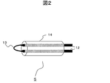
- a metal wire that is processed into a loop shape and can be energized is used as the sample heating mechanism 5, as shown in FIG. 2, a metal wire that is processed into a loop shape and can be energized is used. By energizing through the electrode 12, the metal wire 13 becomes high temperature due to Joule heat, and the foreign material sample is heated and vaporized.
- reference numeral 14 denotes an insulator which also serves as a support for the entire sample heating mechanism.
- a ⁇ 10 ⁇ m Pt wire is used as the metal wire 13
- the electrode 12 connected to the Pt wire is ⁇ 1 mm Cu wire
- the insulator 14 surrounding the electrode 12 is alumina.
- the electrode 12 and the metal wire 13 were connected with a silver paste (not shown).
- the metal wire 13 may be selected according to the size of the foreign material sample to be analyzed. However, at that time, in order to increase the local heating property and heat only the metal wire 13, the electrical resistance value of the metal wire 13 is made higher than that of the electrode 12 and other wiring by reducing the cross section of the metal wire 13 or changing the material. It is desirable to keep it.
- the sample (the substrate 10 and the foreign material sample 9) is mounted on a predetermined sample stage 8 in the chamber, and the sample is observed with an SEM (scanning electron microscope). If the sample coordinates to be analyzed are known in advance using a foreign substance inspection device, etc., it should be observed. Otherwise, the observation should be started from a low magnification, and foreign objects should be searched to determine the analysis target. That's fine.
- a sample having a plurality of analysis objects (foreign material sample 9) on the substrate 10 was used.
- elemental analysis is first performed by EDX.
- the type of foreign material can be identified from the result of EDX, and therefore the next analysis target may be determined.
- mass spectrometry is performed.
- the foreign material sample 9 is first separated from the substrate by the sampling tool 11 attached to the tip of the manipulator 4 and collected at the tip of the tool 11. After that, the metal wire loop heating mechanism 5 is heated close to the foreign material sample 9 and vaporized to perform mass spectrometry. Alternatively, the foreign material sample 9 may be heated and vaporized after being transferred to the metal wire loop heating mechanism 5.
- the vaporized sample is introduced into the mass spectrometer 7 and analyzed.
- the mass spectrometer 7 may be a general-purpose quadrupole mass spectrometer or a time-of-flight mass spectrometer capable of accurate mass analysis.
- an electron impact ion source and a time-of-flight mass spectrometer were used.
- the acceleration voltage of the primary electron beam of the SEM since the organic sample is easily damaged by the electron beam, it is preferable to make the acceleration voltage as low as possible during observation.
- sufficient excitation energy cannot be given at a low acceleration voltage, so it is preferable to select and set the acceleration voltage as appropriate.
- the description has been made on the assumption that mass analysis is performed on an organic sample, but it is also effective to perform an EDX analysis by collecting an inorganic sample with a collection tool. Since information about a depth of several ⁇ m can be obtained with EDX, when the foreign material sample is thin, information on the foreign material and the substrate may be mixed. By collecting a foreign material sample and performing EDX, information from the foreign material and information from the substrate can be reliably separated.
- Example 2 an embodiment in which a laser local heating method is used as a heating mechanism will be described with reference to FIG.
- an electron gun 2, a secondary electron detector 3, an energy dispersive X-ray spectroscopic detector (EDX) 3, a manipulator 4, an ion source 6, and a mass spectrometer 7 are attached to the vacuum chamber 1. It has a structure.
- a laser is used as the sample heating mechanism.
- the laser light 25 emitted from the laser oscillator 21 is irradiated with the laser light 25 condensed on or near the foreign material sample 9 through the semi-transparent mirror 22, the mirror 23, and the objective lens 24.
- an observation CCD camera 26 is installed so that the foreign material sample 9 can be reliably irradiated with laser light.
- Example 1 the mass analysis of the foreign material sample that was found to be an organic substance as a result of the EDX analysis will be described in detail.
- a foreign material sample is collected at the tip using a needle-like tool as the collection tool 15.
- the laser beam 25 focused on the base side is irradiated slightly from the foreign material sample of the needle-like sampling tool 15 to which the foreign material is attached.
- the focused irradiation spot of the laser beam 25 becomes a heat source, and the foreign material sample is heated by the heat conduction.
- the sampling tool 15 since the sampling tool 15 has a conical shape, the heat capacity of the thin tip portion is small and the temperature is instantaneously high, but the thick root portion has a large heat capacity and does not become high temperature. Therefore, only the foreign material sample to be analyzed is heated and vaporized.
- the reason for irradiating the foreign material sample directly to the base side without directly irradiating the foreign material sample is to suppress ablation due to rapid heating of the foreign material sample.
- the foreign material sample may be directly irradiated with laser light.
- a needle-like probe made of tungsten was used as the sampling tool 15, and a laser with a wavelength of 532 nm (second harmonic of YAG) and an output of 1 W was used to irradiate the needle-like sampling tool near the foreign object.
- the laser was about 3 ⁇ m and about 400 mW.
- the material of the sampling tool can be used as long as it has a high melting point and mechanical strength for collecting foreign matter other than tungsten.
- Example 3 An example of using a flea-shaped sampling tool 16 as shown in FIG. Others are the same as Example 2, and there exists the same effect.
- the flea-like sampling tool 16 makes it easy to collect foreign matters that are firmly fixed on the substrate. Collecting the foreign material strongly adhered to the sample substrate 10 can be performed by collecting the foreign material sample because the tip of the needle-like metal probe as shown in the first embodiment is not strong enough to deform the probe tip. Can not.
- the material for the flea-shaped sampling tool 16 diamond, sapphire, SiC, TiN, etc., which can be processed into a sharp cutting edge shape, are suitable.
- the focused laser beam 25 is directly irradiated on the flea-shaped sampling tool 16 near the foreign material sample 9 or the foreign material sample 9 to heat and vaporize the foreign material sample 9.
- the edge part of the tip part of the flea-shaped tool as shown in FIG. 5 narrower than the root part.
- Example 4 Next, an embodiment in which the sampling tool itself has a heating mechanism will be described with reference to FIG.
- a sampling tool 30 was used in which a metal wire was processed in a loop shape so that it could be energized. Others are the same as Example 1, etc., and there exists the same effect. Collect a foreign material sample with a looped wire at the tip. When the foreign material sample is energized in the state of being collected on the loop-shaped wire, the wire becomes high temperature due to Joule heat, and the foreign material sample is heated and vaporized.
- the foreign material sampling and heating probe was formed with a tungsten wire having a diameter of 50 ⁇ m.
- the material and thickness of the metal wire may be determined from the size of the foreign material sample to be analyzed and the degree of adhesion of the foreign material to the substrate.
- reference numeral 30 denotes the same local heating probe as described in the fourth embodiment, in which a metal wire is processed into a loop shape.
- the foreign material sample 31 is widely distributed on the substrate, but it may be very thin and difficult to collect. A method for analyzing such foreign matter will be described. First, after observing by SEM and confirming the position of the foreign material 31, the local heating probe 30 is brought close to the substrate and heated without collecting the foreign material 31. Foreign matter information can be obtained by introducing the sample 31 vaporized by heating into the mass analyzer 7 and analyzing it.
- the local heating probe may be brought into contact with the substrate or may be brought close without being brought into contact. What is necessary is just to select suitably according to the kind of board
- the laser beam 25 condensed by the objective lens 24 is directly applied to the foreign material sample 9 on the sample substrate 10, and the foreign material sample 9 is heated and vaporized to perform mass spectrometry.
- Other points are the same as those of the fifth embodiment, and the same effects are obtained.
- the focused laser beam 25 may be irradiated on the sample substrate 10 in the vicinity of the foreign material sample 9 without irradiating it directly on the foreign material sample 9.
- the collected laser beam 25 is directly applied to the foreign material sample 9, ablation-like vaporization occurs.
- the sample foreign material 9 is vaporized by irradiation of the sample substrate 10 and its thermal conduction, it becomes thermal evaporation.
- SYMBOLS 1 Vacuum chamber, 2 ... Electron gun, 3 ... Energy dispersive X-ray spectroscopic detector (EDX), 4 ... Manipulator, 5 ... Sample heating mechanism, 6 ... Ion source 7 ... Mass spectrometer, 8 ... Sample stage, 9 ... Foreign material sample, 10 ... Sample substrate, 11 ... Sampling tool, 21 ... Laser oscillator, 22 ... Semi-transparent mirror , 23... Mirror, 24... Objective lens, 25... Condensed laser light, 30.
- EDX Energy dispersive X-ray spectroscopic detector
Landscapes
- Chemical & Material Sciences (AREA)
- Analytical Chemistry (AREA)
- General Health & Medical Sciences (AREA)
- Life Sciences & Earth Sciences (AREA)
- Health & Medical Sciences (AREA)
- Biochemistry (AREA)
- Physics & Mathematics (AREA)
- General Physics & Mathematics (AREA)
- Immunology (AREA)
- Pathology (AREA)
- Other Investigation Or Analysis Of Materials By Electrical Means (AREA)
- Sampling And Sample Adjustment (AREA)
- Analysing Materials By The Use Of Radiation (AREA)
Abstract
デバイス等の不良原因となる数μm程度の有機微小異物をSEM中で高感度に分析できる質量分析手法を提供することを目的とする。そのために、SEMチャンバ内に、微小試料を加熱するための加熱機構、気化した試料を分析するための質量分析計を取り付ける。こうすることにより、SEM中で観察した異物をSEMの真空チャンバから取り出すことなく、そのまま微小有機異物の質量分析が可能となる。またEDXとの併用で無機/有機異物ともに同定可能となり、異物分析を高スループットに行うことができる。
Description
本発明は,微小または微量な分析試料の組成を同定するための分析技術に関する。
精密な電子デバイスの製造工程で発生する数μm程度の微小異物は製品の不良原因となるため、対策には異物発生源を特定する必要がある。異物種を同定するために広く用いられている手法としてSEM-EDX(Scanning Electron Microscope - Energy Dispersive X-ray spectroscopy)がある。SEM-EDXは1μm程度の異物の元素を同定でき、金属や金属酸化物などの無機化合物の同定には非常に有効な手段である。一方で、有機物に対しては炭素(カーボン)含まれているといった情報しか与えず有機物の同定には不向きである。特に有機材料を多用する液晶ディスプレイの製造工程では高分子有機物の微小異物が歩留り低下の一因となっており、微小有機異物の同定技術が求められている。有機異物の分析/同定には,通常,顕微ラマンや顕微FT-IRといった分光手法が用いられる。これら分光法を用いると有機物の分子構造に関する多くの情報が得られ,未知の有機物の同定には非常に有用なツールとなる。しかしFT-IRは赤外光を用いるため空間分解能が10μm程度と大きく,数μmの微小異物には適用できない場合が多い。また,製造工程で200℃以上の熱履歴を経た高分子有機異物や、SEM-EDX分析などで一旦電子線を照射された有機異物はレーザ照射により蛍光を発することが多く顕微ラマン分光法でも同定できない場合が多い。このような場合,質量分析法が未知の有機化合物の同定に有効である。質量分析法では試料を気化させてイオン化する必要があるが,高分子有機物のような揮発しにくい試料は,通常,急速加熱により熱分解させる必要がある。熱分解により元の分子に由来するフラグメントイオンのマススペクトルが得られ,未知試料の同定が可能となる。
市販のガスクロマトグラフ質量分析装置の直接導入プローブを用いる場合,通常φ1mm×深さ数mm程度の石英ガラスの容器内に微小サンプルを挿入することになる。微小異物の入った石英ガラス容器をヒータで加熱し,試料を熱分解・気化させて分析を行う。また,ガスクロマトグラフのキャピラリカラムの前段階に装着された熱分解装置に微小異物試料を導入する際にも専用の試料容器等へのセットが必要となる。例えば熱分解装置としてキューリポイントパイロライザを使用する際には数mm角程度の強磁性体の薄片(パイロホイル)に試料を包み,これに高周波を印加してパイロホイルのキューリ点まで瞬時のうちに加熱して試料の熱分解・気化を行う。また,試料をPt容器にセットして,加熱されている炉内に落下させ急速加熱を行う機構の装置もある。さらには特許文献1,特許文献2のように試料保持部をフィラメントで構成し,通電することにより試料を加熱・気化させる方式もある。
上記特許文献1,特許文献2,特許文献3で示される質量分析用プローブによる分析では、分析前処理として試料を分析用のプローブに付着させる必要があり、これをサンプリングと呼んでいる。通常サンプリングは分析装置とは別装置で行うため複数の試料を分析する場合には、
(1)試料のサンプリング
(2)質量分析
という操作を繰り返さなければならない。サンプリングと質量分析を別装置で行う必要があるため、スループットの点でも非常に無駄の多いプロセスである。
(1)試料のサンプリング
(2)質量分析
という操作を繰り返さなければならない。サンプリングと質量分析を別装置で行う必要があるため、スループットの点でも非常に無駄の多いプロセスである。
また、実際には材質が未知の異物分析はまず初めにSEM-EDX分析を行うのが常套手段であり、有機分析は次のステップで行われることが多い。したがって、SEM-EDXの後、装置を替えて、サンプリング、質量分析を行う必要があった。こうした装置間の移動は分析を進める上で、スループットを低下させるネックとなっていた。量産現場などで異物対策を迅速に進める上では、スループットの向上がカギを握る。
上記の課題を解決するために,本発明はSEM-EDXの汎用的な異物分析手法の性能を維持したまま、有機分析も可能にする機能を持たせるために考案されたものである。すなわちSEMのチャンバ内またはそれに連通するように試料加熱機構と質量分析部とを設けたものである。
基板上に分析対象とする異物が複数個ある場合、従来方法では、まずSEM-EDXで分析を行い、カーボンが検出された有機物の位置情報を記録した上でSEMから取り出した後、サンプリングを行う必要がある。サンプリングにより、異物を分析プローブで採取した後、質量分析装置に導入し、加熱・気化を行い質量分析を実施する。質量分析装置は、通常1試料しか導入できないため、試料が複数個ある場合には、サンプリング装置および質量分析へのプローブの着脱を繰り返す必要がある。加えて、質量分析は真空下で行うため、試料交換のたびに真空排気/リークを繰り返す必要があり、分析のスループットの障害となる。
本発明では、SEM中で真空チャンバから試料を出すことなく、質量分析までを一貫して行えるようにした。すなわち、SEMチャンバ内に、試料を加熱気化させる試料加熱機構と、有機物の同定が可能な質量分析計とを備えた装置を考案した。
本発明は,真空引きした同一またはそれに連通する空間で無機物および有機物の微小試料を同定分析できる装置を提供することにより、試料の同定分析を迅速に行うことができる。
以下、本発明の実施例を図面を用いて説明する。
<実施例1>
第1の実施例を図1を用いて説明する。真空チャンバ1に、電子銃2、エネルギ分散型X線分光検出器(EDX)3、マニピュレータ4、試料加熱機構5、イオン源6、質量分析計7が取り付けられている。真空チャンバ1内に設置されている試料台8上に分析対象である異物試料9が付着している試料基板10を搭載する構成となっている。他に、二次電子像を観察するための二次電子検出器、試料を出し入れするためのフランジ、真空系、他の制御系なども接続されるが、それらは省略してある。マニピュレータ4の先端には、微小試料を採取するための採取工具11が取り付けられている。採取工具11は対象によって、針状工具や、ヘラ状工具などを適当に選べばよい。
第1の実施例を図1を用いて説明する。真空チャンバ1に、電子銃2、エネルギ分散型X線分光検出器(EDX)3、マニピュレータ4、試料加熱機構5、イオン源6、質量分析計7が取り付けられている。真空チャンバ1内に設置されている試料台8上に分析対象である異物試料9が付着している試料基板10を搭載する構成となっている。他に、二次電子像を観察するための二次電子検出器、試料を出し入れするためのフランジ、真空系、他の制御系なども接続されるが、それらは省略してある。マニピュレータ4の先端には、微小試料を採取するための採取工具11が取り付けられている。採取工具11は対象によって、針状工具や、ヘラ状工具などを適当に選べばよい。
本実施例では、試料加熱機構5として図2に示すように金属ワイヤをループ状に加工し通電できるようにしたものを用いた。電極12を介し通電することにより金属ワイヤ13はジュール熱で高温となり、異物試料は加熱・気化される。ここで14は絶縁体で試料加熱機構全体の支持部も兼ねている。本実施例では、金属ワイヤ13としてφ10μmのPtワイヤ、それに接続される電極12はφ1mmのCu線、電極12を包む絶縁体14はアルミナとした。また電極12と金属ワイヤ13とを銀ペースト(図示せず)で接続した。金属ワイヤ13は分析対象とする異物試料の大きさに応じて選べばよい。ただしそのとき、局所加熱性を高め金属ワイヤ13のみを加熱させるため、金属ワイヤ13の断面を小さくするまたは材料を変える等により、金属ワイヤ13の電気抵抗値を電極12ならびにその他の配線より高くしておくことが望ましい。
分析方法について説明する。まず試料(基板10及び異物試料9)をチャンバ内の所定の試料台8に装着し、SEM(走査型電子顕微鏡)により試料を観察する。予め、異物検査装置などで分析対象とする試料座標が分かっていればそこを観察すればよいし、そうでなければ拡大倍率が低倍から観察を始め、異物を探索して分析対象を決定すればよい。ここでは基板10上に複数個の分析対象(異物試料9)がある試料を用いた。分析対象とする異物試料9を決定したら、まずEDXで元素分析を行う。異物試料が無機物であれば、EDXの結果から異物種を同定できるので、次の分析対象を決めればよい。EDX分析の結果、炭素(カーボン)が多く検出され有機物であることが分かったら次に質量分析を行う。この場合、まずマニピュレータ4先端に取り付けた採取工具11で異物試料9を基板から分離させ、工具11先端に採取する。その後、金属ワイヤループ状の加熱機構5を異物試料9に近づけて加熱し、気化させて質量分析を行う。または異物試料9を金属ワイヤループ状の加熱機構5に移し替えてから加熱し、気化させても良い。
気化した試料は、質量分析計7の導入され、分析が行われる。質量分析計7は汎用的な四重極質量分析計でもよいし、精密質量分析が可能な飛行時間型質量分析計でもよい。本実施例では、電子衝撃型イオン源と飛行時間型質量分析計を用いた。SEMの一次電子線の加速電圧に特に制限は設けないが、有機物試料は電子線によるダメージを受けやすいため、観察時にはなるべく低加速電圧とすることが好ましい。ただしEDX分析の際、元素によっては低加速電圧では十分な励起エネルギを与えられないため、適宜加速電圧を選択し設定するのが好ましい。
実証実験として、アルミ基板上のφ3μmポリスチレンビーズを模擬異物に見立てて実験を行った。SEM観察の後、採取工具に採り、加熱機構により加熱して質量分析を行い、スチレンモノマーのマススペクトルを得た。
本実施例では、有機物試料を質量分析する場合を前提に説明したが、無機物試料を採取工具で採取してEDX分析することも有効である。EDXは深さ数μm程度の情報が得られるため、異物試料が薄い場合には異物と基板との情報が混合してしまう場合がある。異物試料を採取してEDXを行うことにより、確実に異物からの情報と基板からの情報とを分離することができる。
<実施例2>
次に,加熱機構としてレーザ局所加熱方式を用いた場合の実施例について図3を用いて説明する。実施例1と同様、真空チャンバ1に、電子銃2、二次電子検出器3、エネルギ分散型X線分光検出器(EDX)3、マニピュレータ4、イオン源6、質量分析計7が取り付けられた構造となっている。本実施例では、試料加熱機構としてレーザを用いる。レーザ発振器21から出射されたレーザ光を半透鏡22、ミラー23、対物レンズ24を介して異物試料9上または近傍に集光させたレーザ光25を照射する方式とした。また異物試料9に確実にレーザ光を照射できるよう観察用CCDカメラ26を設置した。
次に,加熱機構としてレーザ局所加熱方式を用いた場合の実施例について図3を用いて説明する。実施例1と同様、真空チャンバ1に、電子銃2、二次電子検出器3、エネルギ分散型X線分光検出器(EDX)3、マニピュレータ4、イオン源6、質量分析計7が取り付けられた構造となっている。本実施例では、試料加熱機構としてレーザを用いる。レーザ発振器21から出射されたレーザ光を半透鏡22、ミラー23、対物レンズ24を介して異物試料9上または近傍に集光させたレーザ光25を照射する方式とした。また異物試料9に確実にレーザ光を照射できるよう観察用CCDカメラ26を設置した。
実際の観察、分析において、実施例1と同様に、EDX分析の結果有機物であることが分かった異物試料の質量分析について詳細を説明する。まず採取工具15として針状の工具を用い先端部に異物試料を採取する。図4に示すように、異物が付着している針状採取工具15の異物試料よりやや根元側に集光したレーザ光25を照射する。まず集光したレーザ光25の照射スポットが熱源となり、その熱伝導で異物試料が加熱される。このとき、採取工具15が円錐状であるため、細い先端部の熱容量は小さく瞬時に高温となるが、太い根元部分は熱容量が大きく高温とはならない。したがって分析対象である異物試料だけが加熱・気化される。異物試料に直接レーザ光を照射せず、やや根元側に照射するのは、異物試料の急激な加熱によるアブレーションを抑制するためである。アブレーションを目的とする場合には異物試料に直接レーザ光を照射させても良い。
本実施例では、採取工具15としてタングステン製の針状プローブを用い、波長532nm(YAGの第二高調波)、出力1Wのレーザを用い、異物近傍の針状採取工具に照射した。金属プローブ上でレーザはφ約3μmで、約400mWだった。採取工具の材料は、タングステン以外でも、融点が高く、異物を採取するための機械的強度が備わっていれば使用可能である。
<実施例3>
次に、レーザ光を照射させる加熱方式において、採取工具として図5に示すようなノミ状の採取工具16を用いる例を示す。他は実施例2と同じであり、同様の効果を奏する。
次に、レーザ光を照射させる加熱方式において、採取工具として図5に示すようなノミ状の採取工具16を用いる例を示す。他は実施例2と同じであり、同様の効果を奏する。
ノミ状の採取工具16を用いることにより、基板上に強く固着しているような異物の採取が容易となる。試料基板10に強く固着している異物の採取は、実施例1で示したような針状の金属プローブでは先端の強度が十分でないためプローブ先端が変形してしまい、異物試料を採取することができない。ノミ状採取工具16の材質としては、先端を鋭い刃先形状に加工できる、ダイヤモンド、サファイア、SiC、TiNなどが好適である。集光したレーザ光25を異物試料9近傍のノミ状採取工具16上、または異物試料9に直接照射して異物試料9を加熱、気化させる。またノミ状採取工具16の形状としては、図5に示すようなノミ状の工具の先端部の刃先部分を根元部分よりも狭くすることが好ましい。こうすることで、レーザ照射時の局所加熱性を高めることができる。
<実施例4>
次に、採取工具自体に加熱機構を持たせた場合の実施例を図6を用いて説明する。採取工具として、金属ワイヤをループ状に加工し通電できるようにした採取工具30を用いた。他は実施例1などと同じであり、同様の効果を奏する。先端のループ状のワイヤで異物試料を採取する。異物試料をループ状ワイヤに採取した状態で通電すると、ワイヤはジュール熱で高温となり、異物試料は加熱・気化される。
次に、採取工具自体に加熱機構を持たせた場合の実施例を図6を用いて説明する。採取工具として、金属ワイヤをループ状に加工し通電できるようにした採取工具30を用いた。他は実施例1などと同じであり、同様の効果を奏する。先端のループ状のワイヤで異物試料を採取する。異物試料をループ状ワイヤに採取した状態で通電すると、ワイヤはジュール熱で高温となり、異物試料は加熱・気化される。
本実施例では、異物採取性と局所加熱性とを両立する構成とすることが重要である。そのため、異物試料採取兼加熱プローブをφ50μmのタングステンワイヤで成形した。分析対象とする異物試料の大きさと、異物の基板への付着の度合いから金属ワイヤの材質、太さを決定すればよい。数~数十μmの異物試料を分析対象とする場合、Pt(白金)やW(タングステン)でφ5~100μm程度のワイヤを用いるのが好ましい。
<実施例5>
次に、サンプリングせずに、加熱プローブを用いて基板上の異物試料を直接加熱し、気化・分析する場合の実施例について図7を用いて説明する。
次に、サンプリングせずに、加熱プローブを用いて基板上の異物試料を直接加熱し、気化・分析する場合の実施例について図7を用いて説明する。
図中30は実施例4で説明したものと同じ、金属ワイヤをループ状に加工した局所加熱プローブである。異物試料31は基板上に広く分布しているが、非常に薄く採取は困難な場合がある。こうした異物の分析方法を説明する。まず、SEMにより観察し、異物31の位置を確認後、異物31を採取せず、基板上に局所加熱プローブ30を近づけて加熱する。加熱により気化した試料31を、質量分析器7に導入して分析することで異物情報が得られる。
このとき局所加熱プローブは基板に接触させる場合と、接触はさせずに近づける場合とがある。基板の種類により適宜選べばよい。例えば、シリコン基板のように耐熱性があり、加熱時に異物以外は気化しないような場合は基板に接触させてかまわない。一方、有機基板や、液晶パネルのカラーフィルタ基板のように、基板自体に有機物が多用されている場合は、接触させないことが好ましい。
<実施例6>
次に、サンプリングせずに、基板上の異物試料をレーザ光の照射により加熱気化させる方法の実施例について図8を用いて説明する。
次に、サンプリングせずに、基板上の異物試料をレーザ光の照射により加熱気化させる方法の実施例について図8を用いて説明する。
対物レンズ24で集光されたレーザ光25を試料基板10上の異物試料9に直接照射し、異物試料9を加熱、気化させ質量分析を行う。他の点は、実施例5と同じであり、同様の効果を奏する。
レーザ光25を照射するときには、集光したレーザ光25を異物試料9に直接当たるように照射せず、異物試料9近傍の試料基板10上に照射してもかまわない。集光したレーザ光25を異物試料9に直接照射するとアブレーション的な気化となり、試料基板10に照射しその熱伝導で試料異物9が気化する場合には熱的な気化となる。
1・・・真空チャンバ、2・・・電子銃、3・・・エネルギ分散型X線分光検出器(EDX)、4・・・マニピュレータ、5・・・試料加熱機構、6・・・イオン源、7・・・質量分析計、8・・・試料台、9・・・異物試料、10・・・試料基板、11・・・採取工具、21・・・レーザ発振器、22・・・半透鏡、23・・・ミラー、24・・・対物レンズ、25・・・集光したレーザ光、30・・・異物採取兼加熱プローブ、31・・・極薄異物。
Claims (11)
- 電子銃により電子を試料に照射して観察するSEMと、
試料を加熱する加熱機構と、
加熱により気化した試料を質量分析する質量分析部と、を備え、
前記SEMの電子銃、前記加熱機構及び前記質量分析部とは、内部を真空引きする同一のチャンバ内またはそれに連通する空間に設けられていることを特徴とする微小試料分析装置。 - 請求項1において、
前記試料を採取して保持するサンプリング機構を備え、
前記加熱機構は、サンプリング機構に保持された試料を加熱することを特徴とする微小試料分析装置。 - 請求項2において、
前記SEMにより前記試料を観察しながら、前記サンプリング機構により前記試料を採取することを特徴とする微小試料分析装置。 - 請求項1において、
前記試料は、基板上の試料であり、
前記加熱機構は、前記基板上の試料を加熱することを特徴とする微小試料分析装置。 - 請求項1乃至4のいずれかにおいて、
前記チャンバ内に、前記試料を元素分析するEDXを備えたことを特徴とする微小試料分析装置。 - 請求項1乃至5のいずれかにおいて、
前記加熱機構は、金属線で構成され、前記金属線への電流供給により前記試料を加熱することを特徴とする微小試料分析装置。 - 請求項1乃至5のいずれかにおいて、
前記加熱機構は、レーザ光を発振するレーザ発振器であることを特徴とする微小試料分析装置。 - 請求項7において、
前記レーザ発振器は、前記試料に直接レーザを照射する、または、前記試料の近傍の前記サンプリング機構もしくは前記基板に照射することを特徴とする微小試料分析装置。 - 請求項2または請求項3において、
前記サンプリング機構は、マニピュレータと、先端が針状の微小試料採取工具とを有しているいることを特徴とする微小試料分析装置。 - 請求項2または請求項3において、
前記サンプリング機構は、マニピュレータと刃先形状を有する微小試料採取工具とを有することを特徴とする微小試料分析装置。 - SEMにより試料を観察する観察工程と、
試料を加熱する加熱工程と、
加熱により気化した試料を分析する質量分析工程と、
を含み、
前記観察工程、前記加熱工程、前記質量分析工程とを、内部を真空引きした同一のチャンバ内または当該チャンバに連通した空間で行うことを特徴とする微小試料分析方法。
Applications Claiming Priority (2)
| Application Number | Priority Date | Filing Date | Title |
|---|---|---|---|
| JP2010157423A JP2012021775A (ja) | 2010-07-12 | 2010-07-12 | 微小試料分析装置及び方法 |
| JP2010-157423 | 2010-07-12 |
Publications (1)
| Publication Number | Publication Date |
|---|---|
| WO2012008089A1 true WO2012008089A1 (ja) | 2012-01-19 |
Family
ID=45469109
Family Applications (1)
| Application Number | Title | Priority Date | Filing Date |
|---|---|---|---|
| PCT/JP2011/003327 WO2012008089A1 (ja) | 2010-07-12 | 2011-06-13 | 微小試料分析装置及び方法 |
Country Status (2)
| Country | Link |
|---|---|
| JP (1) | JP2012021775A (ja) |
| WO (1) | WO2012008089A1 (ja) |
Cited By (1)
| Publication number | Priority date | Publication date | Assignee | Title |
|---|---|---|---|---|
| WO2014175074A1 (ja) * | 2013-04-23 | 2014-10-30 | 株式会社日立ハイテクノロジーズ | 荷電粒子線装置及び当該装置を用いる試料作製方法 |
Families Citing this family (5)
| Publication number | Priority date | Publication date | Assignee | Title |
|---|---|---|---|---|
| US10384238B2 (en) | 2007-09-17 | 2019-08-20 | Rave Llc | Debris removal in high aspect structures |
| JP2017167007A (ja) * | 2016-03-17 | 2017-09-21 | 国立大学法人 東京大学 | 位置決め装置、密閉容器、および真空チャンバ |
| US10217621B2 (en) * | 2017-07-18 | 2019-02-26 | Applied Materials Israel Ltd. | Cleanliness monitor and a method for monitoring a cleanliness of a vacuum chamber |
| WO2023175908A1 (ja) * | 2022-03-18 | 2023-09-21 | 株式会社日立ハイテク | 分析システム、分析方法、分析プログラム |
| WO2023175907A1 (ja) * | 2022-03-18 | 2023-09-21 | 株式会社日立ハイテク | 分析システム、分析方法、分析プログラム |
Citations (8)
| Publication number | Priority date | Publication date | Assignee | Title |
|---|---|---|---|---|
| JPH0996614A (ja) * | 1995-09-29 | 1997-04-08 | Advantest Corp | 微小領域の表面不純物の分析方法およびこの方法を実施する装置 |
| WO1997019343A1 (fr) * | 1995-11-21 | 1997-05-29 | Advantest Corporation | Procede et appareil pour analyser des impuretes de surface, sur une toute petite zone |
| JPH09320512A (ja) * | 1996-05-27 | 1997-12-12 | Sony Corp | 質量分析装置用直接試料導入プローブのフィラメント |
| JPH10213479A (ja) * | 1997-01-29 | 1998-08-11 | Hitachi Ltd | 試料分析装置 |
| JP2001154112A (ja) * | 1999-12-01 | 2001-06-08 | Hitachi Ltd | 分析・観察装置 |
| JP2008003016A (ja) * | 2006-06-26 | 2008-01-10 | Hitachi Displays Ltd | 微小試料採取プローブ |
| JP2008304340A (ja) * | 2007-06-08 | 2008-12-18 | Hitachi Ltd | 試料分析法および装置 |
| JP2009063327A (ja) * | 2007-09-04 | 2009-03-26 | Sumitomo Electric Ind Ltd | 高分子材料中の微量成分の分析法 |
-
2010
- 2010-07-12 JP JP2010157423A patent/JP2012021775A/ja active Pending
-
2011
- 2011-06-13 WO PCT/JP2011/003327 patent/WO2012008089A1/ja active Application Filing
Patent Citations (8)
| Publication number | Priority date | Publication date | Assignee | Title |
|---|---|---|---|---|
| JPH0996614A (ja) * | 1995-09-29 | 1997-04-08 | Advantest Corp | 微小領域の表面不純物の分析方法およびこの方法を実施する装置 |
| WO1997019343A1 (fr) * | 1995-11-21 | 1997-05-29 | Advantest Corporation | Procede et appareil pour analyser des impuretes de surface, sur une toute petite zone |
| JPH09320512A (ja) * | 1996-05-27 | 1997-12-12 | Sony Corp | 質量分析装置用直接試料導入プローブのフィラメント |
| JPH10213479A (ja) * | 1997-01-29 | 1998-08-11 | Hitachi Ltd | 試料分析装置 |
| JP2001154112A (ja) * | 1999-12-01 | 2001-06-08 | Hitachi Ltd | 分析・観察装置 |
| JP2008003016A (ja) * | 2006-06-26 | 2008-01-10 | Hitachi Displays Ltd | 微小試料採取プローブ |
| JP2008304340A (ja) * | 2007-06-08 | 2008-12-18 | Hitachi Ltd | 試料分析法および装置 |
| JP2009063327A (ja) * | 2007-09-04 | 2009-03-26 | Sumitomo Electric Ind Ltd | 高分子材料中の微量成分の分析法 |
Cited By (4)
| Publication number | Priority date | Publication date | Assignee | Title |
|---|---|---|---|---|
| WO2014175074A1 (ja) * | 2013-04-23 | 2014-10-30 | 株式会社日立ハイテクノロジーズ | 荷電粒子線装置及び当該装置を用いる試料作製方法 |
| JP5899377B2 (ja) * | 2013-04-23 | 2016-04-06 | 株式会社日立ハイテクノロジーズ | 荷電粒子線装置及び当該装置を用いる試料作製方法 |
| US9449786B2 (en) | 2013-04-23 | 2016-09-20 | Hitachi High-Technologies Corporation | Charged particle radiation device and specimen preparation method using said device |
| JPWO2014175074A1 (ja) * | 2013-04-23 | 2017-02-23 | 株式会社日立ハイテクノロジーズ | 荷電粒子線装置及び当該装置を用いる試料作製方法 |
Also Published As
| Publication number | Publication date |
|---|---|
| JP2012021775A (ja) | 2012-02-02 |
Similar Documents
| Publication | Publication Date | Title |
|---|---|---|
| WO2012008089A1 (ja) | 微小試料分析装置及び方法 | |
| Pisonero et al. | Critical revision of GD-MS, LA-ICP-MS and SIMS as inorganic mass spectrometric techniques for direct solid analysis | |
| US10488529B2 (en) | Elemental analysis of organic samples | |
| US20120037797A1 (en) | Desorption and ionization method and device | |
| JP2008003016A (ja) | 微小試料採取プローブ | |
| JP2006079846A (ja) | 試料の断面評価装置及び試料の断面評価方法 | |
| WO2008148557A2 (en) | Sample holder device for ionization chambers for mass spectometry | |
| EP2009420A1 (en) | Method for attaching a sample to a manipulator | |
| JP3965761B2 (ja) | 試料作製装置および試料作製方法 | |
| US6414320B1 (en) | Composition analysis by scanning femtosecond laser ultraprobing (CASFLU). | |
| EP2808887A1 (en) | Measurement plate for MALDI mass spectrometry | |
| US7772568B2 (en) | Micro sample heating probe and method of producing the same, and analyzer using the micro sample heating probe | |
| CN102445489A (zh) | 一种激光解吸和电离的方法 | |
| JP4967830B2 (ja) | 試料分析法および装置 | |
| JP2002116184A (ja) | 半導体デバイス異物分析装置およびシステム | |
| Hues et al. | Ultratrace impurity analysis of wafer surfaces | |
| Aseyev et al. | Ultrafast desorption of molecular ions by XUV-photons, passing through dielectric hollow tip | |
| JP4016981B2 (ja) | 試料作製装置および試料作製方法 | |
| JP2004212206A (ja) | 高分子分析用基板、高分子分析用アレイおよび高分子分析方法 | |
| JP5422350B2 (ja) | 質量分析装置および分析方法 | |
| JP4016969B2 (ja) | 試料作製装置および試料作製方法 | |
| McEnnis et al. | Substrate-related effects on molecular and atomic emission in LIBS of explosives | |
| JPH08189917A (ja) | 質量分析装置 | |
| JP4016970B2 (ja) | 試料作製装置および試料作製方法 | |
| JP2004191262A (ja) | 表面微小領域質量分析装置 |
Legal Events
| Date | Code | Title | Description |
|---|---|---|---|
| 121 | Ep: the epo has been informed by wipo that ep was designated in this application |
Ref document number: 11806426 Country of ref document: EP Kind code of ref document: A1 |
|
| NENP | Non-entry into the national phase |
Ref country code: DE |
|
| 122 | Ep: pct application non-entry in european phase |
Ref document number: 11806426 Country of ref document: EP Kind code of ref document: A1 |