WO2012005285A1 - 電極触媒 - Google Patents
電極触媒 Download PDFInfo
- Publication number
- WO2012005285A1 WO2012005285A1 PCT/JP2011/065456 JP2011065456W WO2012005285A1 WO 2012005285 A1 WO2012005285 A1 WO 2012005285A1 JP 2011065456 W JP2011065456 W JP 2011065456W WO 2012005285 A1 WO2012005285 A1 WO 2012005285A1
- Authority
- WO
- WIPO (PCT)
- Prior art keywords
- electrode catalyst
- carbon
- metal
- oxygen
- group
- Prior art date
- Legal status (The legal status is an assumption and is not a legal conclusion. Google has not performed a legal analysis and makes no representation as to the accuracy of the status listed.)
- Ceased
Links
Images




Classifications
-
- H—ELECTRICITY
- H01—ELECTRIC ELEMENTS
- H01M—PROCESSES OR MEANS, e.g. BATTERIES, FOR THE DIRECT CONVERSION OF CHEMICAL ENERGY INTO ELECTRICAL ENERGY
- H01M4/00—Electrodes
- H01M4/86—Inert electrodes with catalytic activity, e.g. for fuel cells
- H01M4/8647—Inert electrodes with catalytic activity, e.g. for fuel cells consisting of more than one material, e.g. consisting of composites
- H01M4/8652—Inert electrodes with catalytic activity, e.g. for fuel cells consisting of more than one material, e.g. consisting of composites as mixture
-
- C—CHEMISTRY; METALLURGY
- C25—ELECTROLYTIC OR ELECTROPHORETIC PROCESSES; APPARATUS THEREFOR
- C25B—ELECTROLYTIC OR ELECTROPHORETIC PROCESSES FOR THE PRODUCTION OF COMPOUNDS OR NON-METALS; APPARATUS THEREFOR
- C25B11/00—Electrodes; Manufacture thereof not otherwise provided for
- C25B11/04—Electrodes; Manufacture thereof not otherwise provided for characterised by the material
- C25B11/051—Electrodes formed of electrocatalysts on a substrate or carrier
-
- C—CHEMISTRY; METALLURGY
- C25—ELECTROLYTIC OR ELECTROPHORETIC PROCESSES; APPARATUS THEREFOR
- C25B—ELECTROLYTIC OR ELECTROPHORETIC PROCESSES FOR THE PRODUCTION OF COMPOUNDS OR NON-METALS; APPARATUS THEREFOR
- C25B11/00—Electrodes; Manufacture thereof not otherwise provided for
- C25B11/04—Electrodes; Manufacture thereof not otherwise provided for characterised by the material
- C25B11/051—Electrodes formed of electrocatalysts on a substrate or carrier
- C25B11/055—Electrodes formed of electrocatalysts on a substrate or carrier characterised by the substrate or carrier material
- C25B11/057—Electrodes formed of electrocatalysts on a substrate or carrier characterised by the substrate or carrier material consisting of a single element or compound
-
- C—CHEMISTRY; METALLURGY
- C25—ELECTROLYTIC OR ELECTROPHORETIC PROCESSES; APPARATUS THEREFOR
- C25B—ELECTROLYTIC OR ELECTROPHORETIC PROCESSES FOR THE PRODUCTION OF COMPOUNDS OR NON-METALS; APPARATUS THEREFOR
- C25B11/00—Electrodes; Manufacture thereof not otherwise provided for
- C25B11/04—Electrodes; Manufacture thereof not otherwise provided for characterised by the material
- C25B11/051—Electrodes formed of electrocatalysts on a substrate or carrier
- C25B11/073—Electrodes formed of electrocatalysts on a substrate or carrier characterised by the electrocatalyst material
- C25B11/075—Electrodes formed of electrocatalysts on a substrate or carrier characterised by the electrocatalyst material consisting of a single catalytic element or catalytic compound
-
- H—ELECTRICITY
- H01—ELECTRIC ELEMENTS
- H01M—PROCESSES OR MEANS, e.g. BATTERIES, FOR THE DIRECT CONVERSION OF CHEMICAL ENERGY INTO ELECTRICAL ENERGY
- H01M4/00—Electrodes
- H01M4/86—Inert electrodes with catalytic activity, e.g. for fuel cells
- H01M4/8647—Inert electrodes with catalytic activity, e.g. for fuel cells consisting of more than one material, e.g. consisting of composites
- H01M4/8657—Inert electrodes with catalytic activity, e.g. for fuel cells consisting of more than one material, e.g. consisting of composites layered
-
- H—ELECTRICITY
- H01—ELECTRIC ELEMENTS
- H01M—PROCESSES OR MEANS, e.g. BATTERIES, FOR THE DIRECT CONVERSION OF CHEMICAL ENERGY INTO ELECTRICAL ENERGY
- H01M4/00—Electrodes
- H01M4/86—Inert electrodes with catalytic activity, e.g. for fuel cells
- H01M4/90—Selection of catalytic material
- H01M4/9016—Oxides, hydroxides or oxygenated metallic salts
-
- H—ELECTRICITY
- H01—ELECTRIC ELEMENTS
- H01M—PROCESSES OR MEANS, e.g. BATTERIES, FOR THE DIRECT CONVERSION OF CHEMICAL ENERGY INTO ELECTRICAL ENERGY
- H01M4/00—Electrodes
- H01M4/86—Inert electrodes with catalytic activity, e.g. for fuel cells
- H01M4/8605—Porous electrodes
-
- H—ELECTRICITY
- H01—ELECTRIC ELEMENTS
- H01M—PROCESSES OR MEANS, e.g. BATTERIES, FOR THE DIRECT CONVERSION OF CHEMICAL ENERGY INTO ELECTRICAL ENERGY
- H01M4/00—Electrodes
- H01M4/86—Inert electrodes with catalytic activity, e.g. for fuel cells
- H01M4/8663—Selection of inactive substances as ingredients for catalytic active masses, e.g. binders, fillers
- H01M4/8673—Electrically conductive fillers
-
- H—ELECTRICITY
- H01—ELECTRIC ELEMENTS
- H01M—PROCESSES OR MEANS, e.g. BATTERIES, FOR THE DIRECT CONVERSION OF CHEMICAL ENERGY INTO ELECTRICAL ENERGY
- H01M4/00—Electrodes
- H01M4/86—Inert electrodes with catalytic activity, e.g. for fuel cells
- H01M4/88—Processes of manufacture
-
- Y—GENERAL TAGGING OF NEW TECHNOLOGICAL DEVELOPMENTS; GENERAL TAGGING OF CROSS-SECTIONAL TECHNOLOGIES SPANNING OVER SEVERAL SECTIONS OF THE IPC; TECHNICAL SUBJECTS COVERED BY FORMER USPC CROSS-REFERENCE ART COLLECTIONS [XRACs] AND DIGESTS
- Y02—TECHNOLOGIES OR APPLICATIONS FOR MITIGATION OR ADAPTATION AGAINST CLIMATE CHANGE
- Y02E—REDUCTION OF GREENHOUSE GAS [GHG] EMISSIONS, RELATED TO ENERGY GENERATION, TRANSMISSION OR DISTRIBUTION
- Y02E60/00—Enabling technologies; Technologies with a potential or indirect contribution to GHG emissions mitigation
- Y02E60/30—Hydrogen technology
- Y02E60/50—Fuel cells
Definitions
- the present invention relates to an electrode catalyst.
- the electrode catalyst is a solid catalyst supported on an electrode, in particular, a surface portion of the electrode, and is used in, for example, an electrochemical system such as a fuel cell in addition to water electrolysis and organic electrolysis.
- an electrode catalyst used in an acidic electrolyte a noble metal, particularly platinum, is widely used because it is stable even at a high potential in the acidic electrolyte.
- tungsten carbide is known as an electrode catalyst that is relatively inexpensive and can be used in an acidic electrolyte (see Non-Patent Document 1), and as an electrode catalyst that is difficult to dissolve when used at a high potential, zirconium oxide is used.
- an electrode catalyst comprising see Non-Patent Document 2.
- the above-mentioned tungsten carbide has a problem that it dissolves at a high potential, and an electrode catalyst made of zirconium oxide has a small current value that can be taken out during use, and these electrode catalysts can be sufficiently satisfied as an electrode catalyst. It is not a thing.
- An object of the present invention is to provide an electrode catalyst that can be used in place of a conventionally used electrode catalyst having platinum as a forming material, and more specifically, using a material that is relatively inexpensive and has a relatively large amount of resources.
- Another object of the present invention is to provide a highly active electrode catalyst that can be obtained and can be used in an acidic electrolyte at a high potential.
- the present invention provides the following.
- a metal compound containing one or more metal elements selected from the group consisting of Group 4 elements and Group 5 elements in the long-period periodic table and an oxygen atom, and at least a part of the metal compound are covered.
- An electrode catalyst having a crystallinity index of 4.5 or more and 8.0 or less, which is 0.170 or less and a peak value of the second adjacent element in the radial distribution function.
- an electrode catalyst that exhibits relatively high activity without dissolving even at a high potential in an acidic electrolyte.
- an electrode catalyst can be obtained using a material that is relatively inexpensive and has a relatively large amount of resources, and the present invention is extremely useful industrially.
- the electrode catalyst of the present embodiment includes one or more metal elements selected from the group consisting of Group 4 elements and Group 5 elements in the long-period periodic table, and a metal compound containing an oxygen atom, And an oxygen defect index of 0.125 or more and 0.170 or less, and a crystallinity index of 4.5 or more and 8.0 or less.
- the oxygen defect index is the reciprocal of the peak value of the first adjacent element in the radial distribution function obtained by Fourier transforming the EXAFS vibration in the EXAFS measurement of the metal element contained in the metal compound. It is a value represented by
- the crystallinity index is represented by the peak value of the second nearest neighbor element in the radial distribution function obtained by Fourier transforming the EXAFS vibration in the EXAFS measurement of the metal element contained in the metal compound. Value.
- an electrode catalyst can be obtained using a material that is relatively inexpensive and has a relatively large amount of resources, and is relatively high at a relatively high potential of, for example, 0.4 V or more in an acidic electrolyte.
- An electrocatalyst exhibiting activity is obtained.
- the electrode catalyst according to the present invention makes it possible to extract a larger oxygen reduction current in the electrochemical system.
- it demonstrates in order.
- Group 4 element refers to “Group 4 element in the long-period periodic table” unless otherwise specified
- Group 5 element also refers to “Group 5 element” unless otherwise specified. It shall refer to “Group 5 element in long-period periodic table”.
- the metal compound which comprises the electrode catalyst of this embodiment is demonstrated.
- the metal compound constituting the electrode catalyst is composed of one or more metal elements selected from the group consisting of Group 4 elements and Group 5 elements and metal compounds containing oxygen atoms.
- the metal element constituting the metal compound is more preferably Zr, Ti, Ta or Nb, and still more preferably Zr or Ti.
- a zirconium oxide is preferable.
- the metal compound has a particulate form.
- the metal compound is preferably deficient in oxygen atoms on the particle surface. This is because the presence of such an oxygen atom deficient portion can be expected to promote the redox reaction in the catalytic reaction.
- the degree of such oxygen atom deficiency can be expressed by the oxygen defect index described above.
- the oxygen defect index is the radial distribution function obtained by Fourier transforming the EXAFS vibration in the EXAFS measurement using the Kr absorption edge of Zr. It is a value expressed as the reciprocal of the peak value.
- the metal element contained in the metal compound is Nb or Ti
- the oxygen defect index is obtained based on the EXAFS vibration in the EXAFS measurement using the K absorption edge.
- the metal element contained in the metal compound is Ta
- the oxygen defect index can be obtained based on EXAFS vibration in EXAFS measurement using the L3 absorption edge.
- the obtained radial distribution function represents a probability density distribution of atoms existing at a predetermined distance from Zr with Zr as a central atom.
- the element adjacent to the Zr atom is oxygen. That is, when the peak value of the first-position neighboring element is large, it indicates that a large amount of oxygen exists at a position away from Zr by a distance corresponding to the Zr—O bond length in the zirconium oxide crystal.
- the reciprocal is used as an oxygen defect index indicating the degree of oxygen deficiency. ing.
- a large oxygen defect index means that the peak value of the first-position neighboring element is small, indicating that no oxygen atom is present at the position where it should be. That is, when the oxygen defect index is large, the degree of oxygen deficiency is large at the measurement site, and when the oxygen defect index is small, the degree of oxygen deficiency is small at the measurement site.
- the oxygen defect index of the metal compound is preferably 0.125 or more and 0.170 or less, more preferably 0.125 or more and 0.140 or less.
- the metal compound preferably has a more ordered crystal structure in order to achieve high catalytic activity. This is because, when such a crystal structure is prepared, it is possible to expect the effect of not inhibiting the transfer of electrons with the metal compound during the oxidation-reduction reaction in the catalytic reaction, thereby not inhibiting the catalytic reaction.
- the degree of such a crystal state can be expressed by the crystallinity index described above.
- the crystallinity index is the radial distribution function obtained by Fourier transforming EXAFS vibration in the EXAFS measurement using the Kr absorption edge of Zr. It is a value expressed as a peak value.
- the metal element contained in the metal compound is Nb or Ti
- the crystallinity index is obtained based on the EXAFS vibration in the EXAFS measurement using the K absorption edge
- the metal element is Ta
- L3 The crystallinity index is obtained based on EXAFS vibration in EXAFS measurement using the absorption edge.
- Zr is an element arranged next to oxygen, which is the first adjacent element as seen from the Zr atom. That is, when the peak value of the second-position adjacent element is large, it indicates that a large amount of Zr exists at a position away from Zr by a distance corresponding to the Zr—O—Zr bond length in the zirconium oxide crystal. On the contrary, the fact that the peak value of the second-position neighboring element is small means that there is no Zr atom that should be at a predetermined position.
- the cause of the phenomenon that “Zr atoms do not exist at a predetermined position” is considered to be because the crystal structure is broken.
- the second order of the radial distribution function obtained by the above-described measurement is used.
- the peak value of the adjacent element is used as the crystallinity index indicating the state of the crystal structure of the metal compound. That is, when the crystallinity index is large, the crystal structure collapse is small at the measurement site (high crystallinity), and when the crystallinity index is small, the crystal structure collapse is large at the measurement site (low crystallinity). ing.
- the metal compound preferably has a higher crystallinity index, preferably 4.5 or more and 8.0 or less, more preferably 5.0 or more and 7.5 or less, Especially preferably, they are 5.8 or more and 6.8 or less.
- the carbon material which comprises the electrode catalyst of this embodiment includes a material mainly composed of carbon, which is obtained by firing a mixture of a metal compound and an organic material to carbonize the organic material.
- “Containing carbon as a main component” means that the carbon material is a material in which, for example, 95 mol% or more of the total is carbon atoms.
- the carbon material covers at least a part of the surface of the particulate metal compound described above.
- the carbon amount of the electrode catalyst is 0.1% by mass or more and 50% by mass or less, more preferably 0.5% by mass or more and 45% by mass or less, still more preferably 3% by mass or more and 40% by mass or less, and particularly preferably 15% by mass. It is not less than 35% by mass.
- the weight loss rate (Ignition Loss) calculated by the following formula is adopted as the carbon amount.
- the value of the carbon amount calculated by the following formula is used.
- the electrode catalyst of this embodiment preferably has a wide surface area in order to increase the catalytic activity.
- As the surface area of the electrode catalyst a specific surface area determined by a general BET method can be adopted.
- BET specific surface area is preferably not more than 15 m 2 / g or more 500 meters 2 / g, more preferably is 50 m 2 / g or more 300 meters 2 / g or less.
- the carbon material covers at least a part of the metal compound constituting the electrode catalyst.
- the electrode catalyst of the present invention functions as an electrode catalyst as a whole by forming a carbon material that covers the surface of the metal compound from the electron flow required for the catalytic reaction that occurs on the surface (interface) of the metal compound.
- the coverage of the carbon material is within a certain range although it functions as an electrode catalyst even if the coverage of the carbon material is outside a certain range. This is because if the coverage is lower than a certain range, the amount of carbon material covering the metal compound is small, so that the conductivity as an electrode catalyst is low, and good catalytic activity cannot be obtained. In addition, if the coverage is higher than a certain range, the exposed area of the surface of the metal compound that can function as a reaction point for the catalytic reaction is narrowed, so that good catalytic activity cannot be obtained.
- a carbon coverage (g / m ⁇ 2 >) can be calculated
- the carbon coverage is preferably 0.05 or more and 0.5 or less, more preferably 0.1 or more and 0.3 or less. By setting the carbon coverage in this way, the catalytic activity of the electrode catalyst can be further increased.
- Carbon coverage (g / m 2 ) carbon content (mass%) / BET specific surface area (m 2 / g) (3)
- the electrode catalyst of this embodiment can be manufactured by using the following first material and second material as forming materials.
- the first material used for the production of the electrode catalyst of the present embodiment is a precursor of the above-described metal compound.
- the first material is one or more metal elements selected from the group consisting of Group 4 elements and Group 5 elements, hydrogen atoms, nitrogen atoms, chlorine atoms, carbon atoms, boron atoms, sulfur It is a compound composed of one or more non-metallic elements selected from atoms and oxygen atoms.
- the metal element constituting the first material contains a metal element of a Group 4 element or a Group 5 element.
- the metal element is more preferably Zr, Ti, Ta, or Nb, still more preferably Zr or Ti, and particularly preferably Zr.
- a preferable nonmetallic element constituting the first material is one or more nonmetallic elements selected from a hydrogen atom, a chlorine atom and an oxygen atom.
- Examples of the first material when the metal element is Zr include zirconium hydroxide and zirconium oxychloride.
- Examples of the first material when the metal element is Ti include titanium hydroxide, titanium tetrachloride, metatitanic acid, orthotitanic acid, titanium sulfate, and titanium alkoxide. Such a first material can be used in a slurry state using water as a dispersion medium.
- the second material used for manufacturing the electrode catalyst of the present embodiment is the above-described carbon material precursor (carbon material precursor).
- the carbon material precursor is guided to the carbon material by heat treatment (firing) at a high temperature.
- the carbon material precursor examples include sugars such as glucose, fructose, sucrose, cellulose, and hydropropylcellulose; alcohols such as polyvinyl alcohol; glycols such as polyethylene glycol and polypropylene glycol; polyesters such as polyethylene terephthalate; acrylonitrile, poly Nitriles such as acrylonitrile, various proteins such as collagen, keratin, ferritin, hormones, hemoglobin, and albimine, biological materials such as amino acids such as glycine, alanine, and methionine, ascorbic acid, citric acid, stearic acid, and the like.
- the second material is preferably a material having oxygen.
- the electrode catalyst of this embodiment can be manufactured by the following manufacturing method using the above-mentioned first material and second material.
- An electrode catalyst can be manufactured by calcinating the obtained mixed precursor as a mixed precursor, which is a reaction product of a hydrothermal reaction of the material.
- the critical point of water is 374 ° C. (critical temperature) and 22 MPa (critical pressure).
- water in a supercritical state means water having a temperature of 374 ° C. or higher and a pressure of 22 MPa or higher.
- water in a subcritical state is water that maintains a liquid state under high-temperature and high-pressure conditions although its temperature and pressure are lower than the critical point.
- the water in such a subcritical state is preferably water having a temperature of 250 ° C. or higher and a pressure of 20 MPa or higher, and having a temperature lower than the critical point of water and a low pressure.
- a continuous (flow-through) reactor can be used as the reactor for performing the hydrothermal reaction.
- a reaction apparatus for continuously performing a hydrothermal reaction used in the present embodiment will be described.
- the dimensions and ratios of the constituent elements are appropriately changed in order to make the drawings easy to see.
- FIG. 1 is a diagram showing an outline of a flow reactor for continuously performing a hydrothermal reaction.
- the flow-type reaction apparatus reacts the raw material supplied from the raw material tank 22 mainly by a hydrothermal reaction generated in the reactor 40 while flowing in the apparatus under a high temperature and high pressure environment.
- the reaction product is recovered in the recovery container 60.
- Water tanks 11 and 21 are tanks for supplying water.
- the raw material tank 22 is a tank for supplying the raw material slurry.
- the raw material slurry is a slurry or an aqueous solution of a mixed material containing the first material and the second material.
- the stored liquid is supplied into the apparatus by opening the valves 110, 210 and 220, respectively.
- a liquid feed pump 13 provided on the downstream side of the valve 110 sends water from the water tank 11 to the heater 14.
- a liquid feed pump 23 is provided on the downstream side of the joining portion, and sends either or both of water supplied from the water tank 21 and raw slurry supplied from the raw material tank 22 to the heater 24.
- the raw slurry is preliminarily heated.
- the temperature range of the preheating is preferably 100 ° C. to 330 ° C., more preferably 150 ° C. to 300 ° C.
- the hydrothermal reaction of the mixture may be partially performed.
- the sent liquids are mixed in the mixing unit 30, and a reaction is mainly caused by a hydrothermal reaction in the reactor 40.
- FIG. 2 is a diagram showing an outline of the reactor 40.
- the reactor 40 there is an internal pipe 41 and a heater 44 for heating the pipe, and the internal pipe 41 is connected to an external pipe.
- the reaction time can be adjusted by adjusting the length of the internal piping 41 in the reactor 40.
- various shapes such as a zigzag shape and a spiral shape may be selected and used as the shape of the internal pipe 41.
- the material of the piping and internal piping may be selected appropriately based on conditions such as the type of raw slurry and the temperature and pressure of the hydrothermal reaction.
- stainless steel such as SUS316, Hastelloy, Inconel, etc.
- a nickel alloy or a titanium alloy can be used.
- a part or all of the inner surface of the pipe may be lined with a material having high corrosion resistance such as gold.
- the slurry containing the reaction product after the hydrothermal reaction (product slurry) is cooled by a cooler 51 provided on the downstream side of the reactor 40, passes through a filter 52 and a back pressure valve 53. And collected in the collection container 60.
- valve 110 and the valve 210 or the valve 220 are opened, the liquid feeding pumps 13 and 23 are moved, and the back pressure valve 53 is opened and closed to open the valves from the liquid feeding pumps 13 and 23 to the back pressure valve 53.
- the pressure in the piping and the temperature of the heaters 14 and 24 and the heater 44 in the reactor 40 the water flowing in the apparatus can be brought into a supercritical state or a subcritical state. .
- the liquid feed pumps 13 and 23 are activated, the pressure in the piping is adjusted as appropriate using the back pressure valve 53, and the temperatures of the heaters 14 and 24 and the heater 44 in the reactor 40 are appropriately adjusted.
- the temperature is adjusted so that the water in the reactor is in a supercritical state or a subcritical state.
- the raw material slurry before and after the raw material slurry is sent from the raw material tank 22, it is also possible to send water from the water tank 21 to perform preheating of the piping, cleaning of the piping, and the like.
- the particle size of the produced slurry after the hydrothermal reaction may be adjusted by removing coarse particles using the filter 52.
- the produced slurry recovered in the recovery container 60 may be used in a powder state or in a slurry state after solid-liquid separation, washing, and drying in a subsequent manufacturing process such as mixing or baking.
- the target electrode catalyst is obtained by firing the above mixed precursor under conditions that allow the second material to transition to the carbon material.
- the firing atmosphere is preferably fired in an oxygen-free atmosphere in order to efficiently synthesize the electrode catalyst.
- the oxygen-free atmosphere is preferably a nitrogen atmosphere.
- the furnace used for firing may be any furnace that can control the atmosphere, and examples thereof include a tubular electric furnace, a tunnel furnace, a far-infrared furnace, a microwave heating furnace, a roller hearth furnace, and a rotary furnace. However, it is not limited to these. Further, the atmosphere control may be performed batchwise or continuously. Alternatively, the mixed precursor may be fired in a stationary manner in which the mixed precursor is left standing, or may be fired in a fluid manner in which the mixed precursor is fired in a fluid state.
- the firing temperature may be appropriately set according to the type of the second material (carbon material precursor) and the firing atmosphere, but the temperature at which the second material can transition to the carbon material, that is, the temperature at which the second material decomposes and carbonizes. Just do it.
- the firing temperature is, for example, 400 ° C. to 1100 ° C., preferably 500 ° C. to 1000 ° C., more preferably 500 ° C. to 900 ° C., and even more preferably 700 ° C. to 900 ° C.
- the BET specific surface area of the electrode catalyst can be controlled by controlling the calcination temperature.
- the condition that the second material can transition to the carbon material means a condition that the second material can be decomposed and carbonized to become a carbon material.
- the heating rate during firing is not particularly limited as long as it is in a practical range, and is usually 10 ° C./hour to 600 ° C./hour, preferably 50 ° C./hour to 500 ° C./hour. At such a temperature raising rate, the temperature may be raised to the firing temperature and kept for 0.1 to 24 hours, preferably about 1 to 12 hours for firing.
- the electrode catalyst of this embodiment can be manufactured.
- the electrode catalyst according to the present invention makes it possible to extract a larger oxygen reduction current in an electrochemical system.
- the value of oxygen reduction current per unit area of the electrode the preferred value 1000 ⁇ A / cm 2 or more, a more preferred value is 1500 ⁇ A / cm 2 or more.
- An electrode catalyst composition having an electrode catalyst can be prepared using the above-described electrode catalyst.
- the electrode catalyst composition usually has a dispersion medium.
- the electrode catalyst composition can be obtained by dispersing the electrode catalyst in a dispersion medium.
- the dispersion medium include alcohols such as methanol, ethanol, isopropanol, and normal propanol, and water such as ion-exchanged water.
- the mass of the dispersion medium is usually about 1 part by mass to 100 parts by mass, preferably 2 parts by mass to 50 parts by mass with respect to 100 parts by mass of the electrode catalyst. .
- a dispersant When dispersing, a dispersant may be used.
- the dispersant include inorganic acids such as nitric acid, hydrochloric acid, and sulfuric acid, organic acids such as oxalic acid, citric acid, acetic acid, malic acid, and lactic acid, water-soluble zirconium salts such as zirconium oxychloride, ammonium polycarboxylate, and polycarboxylic acid.
- surfactants such as sodium acid
- catechins such as epicatechin, epigallocatechin, and epigallocatechin galade.
- the electrode catalyst composition of the present invention may contain an ion exchange resin.
- an ion exchange resin When it contains an ion exchange resin, it is particularly suitable for a fuel cell.
- the ion exchange resin include fluorine ion exchange resins such as Nafion (registered trademark of DuPont) and hydrocarbon ion exchange resins such as sulfonated phenol formaldehyde resins.
- the electrode catalyst composition of the present invention may contain a conductive material.
- the conductive material include carbon fiber, carbon nanotube, carbon nanofiber, conductive oxide, conductive oxide fiber, and conductive resin.
- the electrode catalyst composition can also contain a noble metal such as Pt or Ru, or a transition metal such as Ni, Fe, or Co. When these noble metals and transition metals are contained, the content is preferably a trace amount (for example, about 0.1 to 10 parts by mass with respect to 100 parts by mass of the electrode catalyst).
- the electrode catalyst of the present embodiment can be used in an electrochemical system, preferably as an electrode catalyst for a fuel cell, more preferably as an electrode catalyst for a polymer electrolyte fuel cell, and still more preferably as a polymer electrolyte. It can be used as an electrode catalyst for the cathode portion of a fuel cell.
- the electrocatalyst of the present embodiment can be suitably used at a potential of 0.4 V or higher with respect to the reversible hydrogen electrode potential in an acidic electrolyte, and has a relatively high activity.
- a potential of 0.4 V or higher with respect to the reversible hydrogen electrode potential in an acidic electrolyte, and has a relatively high activity.
- It is supported on an electrode and is useful as an oxygen reduction catalyst used for reducing oxygen.
- a suitable upper limit of the potential when used as an oxygen reduction catalyst can be used up to about 1.6 V which is a potential for generating oxygen, although it depends on the stability of the electrode catalyst.
- the electrode catalyst is gradually oxidized from the surface simultaneously with the generation of oxygen, and the electrode catalyst may be completely converted into an oxide and deactivated. If the potential is less than 0.4 V, it can be said that it is preferable from the viewpoint of stability of the electrode catalyst, but it may be less useful from the viewpoint of an oxygen reduction catalyst.
- the electrode catalyst composition can be supported on an electrode such as carbon cloth or carbon paper and used for electrolysis of water in an acidic electrolyte, electrolysis of organic matter, or the like. It can also be used by being supported on an electrode constituting a fuel cell such as a polymer electrolyte fuel cell or a phosphoric acid fuel cell.
- the evaluation method in each Example is as follows. (1) The BET specific surface area (m 2 / g) was determined by a nitrogen adsorption method (based on JIS-Z8830 “Method for measuring specific surface area of powder (solid) by gas adsorption”). (2) The crystal structure was determined using a powder X-ray diffractometer (X'Pert Pro MPD, manufactured by PANalytical). (3) The amount of carbon was determined by placing the obtained electrode catalyst in an alumina crucible, calcining it in a box furnace at 1000 ° C. for 3 hours in the atmosphere, and calculating the weight loss rate (Ignition Loss) calculated by the following equation (4): : Gross value).
- the peak value of the first adjacent element (oxygen) that can be seen was employed.
- the peak value of the second nearest neighbor element (zirconium) found at 3.0 to 4.0 mm in the EXAFS results of the transmission XAFS measurement using the Zr-K absorption edge was adopted. Asked.
- Example 1 (Preparation of electrode catalyst) 6 g of glucose (manufactured by Wako Pure Chemical Industries, Ltd.) was added as a second material to 600 mL of the zirconium hydroxide slurry obtained in Production Example 1, and this mixture was used as a raw material tank for a flow reactor (made by ITEC Co., Ltd.). 22 was charged. The water tanks 11 and 21 were charged with water, the liquid feed pumps 13 and 23 were started, the valves 110 and 210 were opened, and the liquid feed of these waters was started. Here, the flow rate in the liquid feed pump 13 was adjusted to 16.7 mL / min, and the flow rate in the liquid feed pump 23 was adjusted to 6.66 mL / min.
- the pressure in the pipe was adjusted to 30 MPa.
- the heater 14 was adjusted to 400 ° C.
- the heater 24 was adjusted to 250 ° C.
- the temperature of the heater 44 in the reactor 40 was adjusted to 350 ° C. It was 380 degreeC when the liquid temperature of the mixing part 30 in a steady state was measured, and it confirmed that it was water of a supercritical state.
- the water tank 21 is switched to the raw material tank 22, the raw material slurry is supplied from the raw material tank 22, and a hydrothermal reaction is performed.
- the recovered product slurry was separated into solid and liquid by filtration, and dried under conditions of 60 ° C. for 3 hours to obtain a mixed precursor.
- the obtained mixed precursor was put into an alumina boat, and in a tubular electric furnace having an internal volume of 13.4 L (manufactured by Motoyama Co., Ltd.), nitrogen gas was circulated at a flow rate of 1.5 L / min.
- the temperature was raised from room temperature (about 25 ° C.) to 800 ° C. at a temperature rate of 300 ° C./hour and calcined by holding at 800 ° C. for 1 hour to obtain an electrode catalyst 1.
- the obtained electrocatalyst 1 was confirmed to be zirconium oxide coated with carbon by performing carbon mapping using EF-TEM.
- the electrode catalyst had a BET specific surface area of 116 m 2 / g, a carbon content of 12.3% by mass, a carbon coverage of 0.11 g / m 2 , and a crystal form of a tetragonal and orthorhombic mixed phase.
- Example 2 Preparation of electrode catalyst
- a commercially available supercritical water nanoparticle synthesis test machine manufactured by ITEC Co., Ltd., MOMI ultra mini
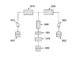
- FIGS. 3 and 4 correspond to FIGS. 1 and 2 described above.
- a mixture obtained by adding 2.6 g of glucose as a second material to 175 g of the zirconium hydroxide slurry obtained in Production Example 2 was placed in the raw material tank 1022 and charged into the flow path.
- the flow rate of the pump 1013 corresponding to the liquid feed pump 13 in FIG. 2 was adjusted to 8 mL / min, and the flow rate of the pump 1023 corresponding to the liquid feed pump 23 in FIG.
- the reaction pressure was set to 20 MPa, and the inside of the flow path of the apparatus was set to a subcritical condition.
- the set temperature of the raw material line heater 1024 corresponding to the heater 24 of FIG. 2 is 180 ° C.
- the set temperature of the pure water line heater 1014 corresponding to the heater 14 of FIG. 2 is 400 ° C.
- the set temperature of the reaction line heater 1040 was 350 ° C.
- the reaction line heater 1040 has an internal pipe 1041 and a heater 1044. By setting the set temperature of the heater 1044 to 350 ° C., the reaction line heater 1040 as a whole has a set temperature. The heating is performed.
- the liquid temperature at the outlet of the raw material line heater 1024 was 180 ° C.
- the obtained slurry was passed through a recovery unit 1070 having functions similar to those of the cooler 51 and the filter 52 in FIG. 2 and then collected in a recovery container 1060 corresponding to the recovery container 60 in FIG.
- the resulting slurry was treated at 3000 rpm for 10 minutes using a centrifuge (model number Model 9912, manufactured by Kubota Corporation), the supernatant was removed, and the precipitate was dried at 60 ° C. to obtain an electrode catalyst.
- a mixed precursor was obtained.
- the obtained mixed precursor was put into an alumina boat, and in a tubular electric furnace having an internal volume of 13.4 L (manufactured by Motoyama Co., Ltd.), nitrogen gas was circulated at a flow rate of 1.5 L / min.
- the temperature was increased from room temperature (about 25 ° C.) to 800 ° C. at a temperature rate of 300 ° C./hour and calcined by holding at 800 ° C. for 1 hour to obtain an electrode catalyst 2.
- the obtained electrode catalyst 2 was confirmed to be zirconium oxide coated with carbon in the same manner as in Example 1.
- the electrode catalyst had a BET specific surface area of 153 m 2 / g, a carbon content of 12.8% by mass, a carbon coverage of 0.08 g / m 2 , and a crystal form of a tetragonal and orthorhombic mixed phase.
- Example 1 (Preparation of electrode catalyst)
- the Zr-containing compound slurry obtained in Production Example 2 was used, and the temperature setting of each heater in the flow reactor used in Example 1 was set except that the heater of the heater 24 was turned off.
- the electrode catalyst 3 was obtained by carrying out similarly to Example 1 and heat-treating the obtained “mixed precursor” in the same manner as in Example 1.
- the liquid temperature of the mixing part 30 in a steady state was measured similarly to Example 1, it was 367 degreeC and it confirmed that it was subcritical water.
- the obtained electrode catalyst 3 was confirmed to be zirconium oxide coated with carbon in the same manner as in Example 1.
- the electrode catalyst had a BET specific surface area of 69 m 2 / g, a carbon content of 4.5 mass%, a carbon coverage of 0.06 g / m 2 , and a crystal form of a tetragonal and orthorhombic mixed phase.
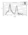
- FIG. 5 is a graph showing a radial distribution function obtained for each electrode catalyst.
- the electrode catalyst 1 had an oxygen defect index of 0.138 and a crystallinity index of 6.8.
- Electrode catalyst 2 had an oxygen defect index of 0.128 and a crystallinity index of 6.0.
- the electrode catalyst 3 had an oxygen defect index of 0.122 and a crystallinity index of 4.0.
- the electrode catalyst was weighed, added to a mixed solvent of 5 mL of pure water and 5 mL of isopropyl alcohol, and irradiated with ultrasonic waves to obtain a suspension. 20 ⁇ L of this suspension was applied to a glassy carbon electrode (6 mm diameter, electrode area 28.3 mm 2 ), dried, and “Nafion (registered trademark)” (manufactured by DuPont, 10% solid content concentration of 5% by mass). A modified electrode in which an electrode catalyst was supported on a glassy carbon electrode was obtained by applying 13 ⁇ L of a double diluted sample), drying, and treating with a vacuum dryer for 1 hour.
- This modified electrode is immersed in a 0.1 mol / L sulfuric acid aqueous solution, and is at ⁇ 0.25 V to 0.75 V (reversible hydrogen chloride) with respect to the silver-silver chloride electrode potential at room temperature, atmospheric pressure, oxygen atmosphere and nitrogen atmosphere.
- the potential was cycled at a scanning speed of 50 mV / s in the scanning range of electrode potential conversion (0.025 V to 1.025 V).
- the current value at each potential for each cycle was compared to confirm electrode stability.
- the oxygen reduction current was determined by comparing the current values of the oxygen atmosphere and nitrogen atmosphere at a potential of 0.4 V with respect to the reversible hydrogen electrode potential.
- the oxygen reduction current of the electrode catalyst 1 shows 2941 ⁇ A / cm 2 per unit area of the electrode
- the oxygen reduction current of the electrode catalyst 2 shows 1963 ⁇ A / cm 2 per unit area of the electrode. It was.
- the oxygen reduction current of the electrode catalyst 3 showed 518 ⁇ A / cm 2 per unit area of the electrode, which was lower than the oxygen reduction current of the electrode catalysts 1 and 2.
- the electrode catalyst of the present invention exhibits a relatively high activity without dissolving even at a high potential in an acidic electrolyte, and is useful as an electrode catalyst that can be substituted for an electrode catalyst using platinum as a forming material.
Landscapes
- Chemical & Material Sciences (AREA)
- Chemical Kinetics & Catalysis (AREA)
- Electrochemistry (AREA)
- Engineering & Computer Science (AREA)
- Materials Engineering (AREA)
- General Chemical & Material Sciences (AREA)
- Organic Chemistry (AREA)
- Metallurgy (AREA)
- Composite Materials (AREA)
- Catalysts (AREA)
- Inert Electrodes (AREA)
- Electrodes For Compound Or Non-Metal Manufacture (AREA)
- Fuel Cell (AREA)
Abstract
Description
[1]長周期型周期表における第4族元素および第5族元素からなる群より選択される1種以上の金属元素および酸素原子を含む金属化合物と、該金属化合物の少なくとも一部を被覆する炭素材料と、を含み、前記金属元素のEXAFS測定におけるEXAFS振動をフーリエ変換することで求められる動径分布関数における、第一位近接元素のピーク値の逆数として示される酸素欠陥指数が0.125以上0.170以下であり、前記動径分布関数における第二位近接元素のピーク値として示される結晶性指数が4.5以上8.0以下である電極触媒。
[2]BET比表面積が15m2/g以上500m2/g以下であり、以下の式(1)により求めた炭素被覆率が0.05g/m2以上0.5g/m2以下である[1]に記載の電極触媒。
[数1]
炭素被覆率(g/m2)=炭素量(質量%)/BET比表面積(m2/g) …(1)
[3]前記金属元素が、ジルコニウム、チタン、タンタルおよびニオブからなる群より選択される1種以上の金属元素である[1]または[2]に記載の電極触媒。
[4]前記金属元素が、ジルコニウムまたはチタンである[1]または[2]に記載の電極触媒。
[5]前記金属元素が、ジルコニウムである[1]または[2]に記載の電極触媒。
[6]前記金属化合物が、酸化ジルコニウムである[5]に記載の電極触媒。
[7][1]~[6]のいずれか一項に記載の電極触媒を有する電極触媒組成物。
本実施形態の電極触媒は、長周期型周期表における第4族元素および第5族元素からなる群より選択される1種以上の金属元素、および酸素原子を含む金属化合物と、該金属化合物の少なくとも一部を被覆する炭素材料とから構成され、酸素欠陥指数が0.125以上0.170以下、かつ結晶性指数が4.5以上8.0以下であることを特徴としている。
まず、本実施形態の電極触媒を構成する金属化合物について説明する。電極触媒を構成する金属化合物は、第4族元素および第5族元素からなる群より選択される1種以上の金属元素および酸素原子を含む金属化合物で構成されている。金属化合物を構成する金属元素は、Zr、Ti、TaまたはNbであることがより好ましく、ZrまたはTiであることがさらにより好ましい。また、本発明の電極触媒を構成する金属化合物としては、酸化ジルコニウムが好ましい。
金属化合物は、粒子状の形態を有している。金属化合物は、粒子表面の酸素原子が欠損している方が好ましい。このような酸素原子の欠損部分の存在により、触媒反応における酸化還元反応が促進される効果が期待できるからである。このような酸素原子の欠損の度合は、上述した酸素欠陥指数で表すことができる。
また金属化合物は、高い触媒活性の実現のために、より整った結晶構造を有している方が好ましい。このような結晶構造が整ったものであると、触媒反応における酸化還元反応時に金属化合物との電子の授受を阻害せず、そのことにより触媒反応を阻害しないという効果が期待できるからである。このような結晶状態の度合は、上述した結晶性指数で表すことができる。
次に、本実施形態の電極触媒を構成する炭素材料について説明する。本実施形態において「炭素材料」とは、金属化合物と有機物との混合物を焼成し、有機物を炭化させることで得られる、炭素を主成分とする材料を含むものである。「炭素を主成分とする」とは、炭素材料が、例えば全体の95mol%以上が炭素原子であるような材料であることを意味している。
[数2]
炭素量(質量%)=重量減少率(質量%)=(WI-WA)/WI×100 …(2)
(ここで、WIは焼成前の電極触媒質量、WAは焼成後の質量である。)
本実施形態の電極触媒は、触媒活性を高めるために表面積が広いものが好ましい。電極触媒の表面積は、一般的なBET法により求めた比表面積を採用することができる。本実施形態の電極触媒においては、BET比表面積が、15m2/g以上500m2/g以下であることが好ましく、より好ましくは、50m2/g以上300m2/g以下である。BET比表面積をこのように設定することで、触媒活性をより高めることができる。
本実施形態の電極触媒は、上述するように電極触媒を構成する金属化合物の少なくとも一部を炭素材料が被覆している。
本発明の電極触媒は、金属化合物の表面(界面)で生じる触媒反応で必要な電子の流れを、金属化合物の表面を覆う炭素材料が形成されることで、全体として電極触媒として機能する。
[数3]
炭素被覆率(g/m2)=炭素量(質量%)/BET比表面積(m2/g) …(3)
次に、本実施形態の電極触媒の製造方法について説明する。本実施形態の電極触媒は、以下の第一材料および第二材料を形成材料として製造することができる。
第二材料は、上記の材料の中でも、酸素を有する材料であることが好ましい。
本実施形態の電極触媒は、上述の第一材料および第二材料を用い、以下の製造方法によって製造することができる。
まず、電極触媒の製造方法に用いられる水熱反応について説明する。
本発明において超臨界状態の水とは、温度374℃以上且つ圧力22MPa以上の水を意味する。
また、本発明において亜臨界状態の水とは、臨界点よりは温度、圧力が低いものの高温高圧条件下で液体状態を保つ水である。このような亜臨界状態の水として、具体的には温度250℃以上且つ圧力20MPa以上であり、且つ水の臨界点より低温、低圧力の水であることが好ましい。
また、本実施形態において、水熱反応を行うための反応装置としては、連続式(流通式)の反応装置を用いることができる。
以下、図1、2を参照しながら、本実施形態において用いる連続的に水熱反応を行うための反応装置について説明する。なお、以下の全ての図面においては、図面を見やすくするため、各構成要素の寸法や比率などは適宜異ならせてある。
図に示すように、流通式反応装置は、原料タンク22から供給される原料を、高温高圧環境下の装置内で流動させながら、主として反応器40内で生じさせる水熱反応により反応させることにより、回収容器60にて反応物を回収するものである。
また、通過する液の特性に応じて、金などの耐食性の高い材料で配管の一部または全部の内面をライニングしてもよい。
次に、電極触媒の製造方法に用いられる焼成工程について説明する。
上述の電極触媒を用いて、電極触媒を有する電極触媒組成物とすることもできる。電極触媒組成物は、通常、分散媒を有する。電極触媒組成物は、電極触媒を分散媒に分散させて得ることができる。分散媒としては、メタノール、エタノール、イソプロパノール、ノルマルプロパノールなどのアルコール類やイオン交換水などの水等があげられる。
また、固体高分子形燃料電池やリン酸形燃料電池等の燃料電池を構成する電極に担持させて用いることもできる。
(1)BET比表面積(m2/g)は、窒素吸着法(JIS-Z8830「気体吸着による粉体(固体)の比表面積測定方法」に準拠)により求めた。
(2)結晶構造は、粉末X線回折装置(X'Pert Pro MPD、PANalytical社製)を用いて行った。
(3)炭素量は、得られた電極触媒をアルミナ坩堝にいれ、箱型炉にて大気雰囲気で1000℃で3時間焼成し、次の式(4)により算出される重量減少率(Ignition Loss:イグロス値)を採用した。
[数4]
炭素量(質量%)=(WI-WA)/WI×100 …(4)(ここで、WIは焼成前の電極触媒質量、WAは焼成後の質量である。)
(4)炭素被覆率は、次の式(5)にて算出した。
[数5]
炭素被覆率(g/m2)=炭素量(質量%)/BET比表面積(m2/g) …(5)
(5)酸素欠陥指数として、Zr-K吸収端を用いた透過法XAFS(X-ray Absorption Fine Structure)測定のEXAFS(Extended X-Ray Absorption Fine Structure)結果において、1.6Å~1.7Åに見られる第一位近接元素(酸素)のピーク値の逆数を採用して求めた。
(6)結晶性指数として、Zr-K吸収端を用いた透過法XAFS測定のEXAFS結果において、3.0Å~4.0Åに見られる第二位近接元素(ジルコニウム)のピーク値を採用して求めた。
オキシ塩化ジルコニウム(和光純薬製)を純水に溶解して得られた水溶液(オキシ塩化ジルコニウム8質量%)と、NH3水溶液(関東化学(株)製、4質量%に希釈)とを用いて、中和を行い、得られた沈殿物をろ過・洗浄して回収した。粉末X線回折測定の結果、この沈殿物は、水酸化ジルコニウムであることが確かめられた。
得られた水酸化ジルコニウムを、pHが10.5に調整されたNH3水溶液に、1質量%となる濃度で分散させ、水酸化ジルコニウムのスラリーを得た。
市販の水酸化ジルコニウム(製品名:R水酸化ジルコニウム、第一稀元素製)をpHが10.5に調整されたNH3水溶液に1質量%となる濃度で分散させ、水酸化ジルコニウムのスラリーを得た。
〔電極触媒の調製〕
製造例1により得られた水酸化ジルコニウムのスラリー600mLに、第二材料としてグルコース(和光純薬製)6gを添加し、この混合物を、流通式反応装置(アイテック(株)社製)の原料タンク22に仕込んだ。水タンク11,21に水を仕込み、送液ポンプ13,23を起動して、弁110、210を開けて、これらの水の送液を開始した。
ここで、送液ポンプ13における流量を16.7mL/分に、送液ポンプ23における流量を6.66mL/分に、それぞれ調節した。背圧弁53を用いて、配管内圧力を30MPaに調節した。加熱器14を400℃に、加熱器24を250℃に、反応器40内の加熱器44の温度を350℃に、それぞれ調節した。定常状態における混合部30の液温を測定したところ380℃であり、超臨界状態の水であることを確認した。
その後、弁210を閉め、弁220を開けることにより、水タンク21から原料タンク22に切り替えて、原料タンク22から原料スラリーを供給して、水熱反応を行い、回収容器60にて、生成スラリーを回収した。回収した生成スラリーをろ過により固液分離し、60℃、3時間の条件で乾燥して、混合前駆体を得た。
得られた混合前駆体を、アルミナ製ボートに入れ、内容積13.4Lの管状型電気炉((株)モトヤマ製)中で、窒素ガスを1.5L/分の流量で流通させながら、昇温速度300℃/時間で室温(約25℃)から800℃まで昇温し、800℃で1時間保持することにより焼成して、電極触媒1を得た。
〔電極触媒の調製〕
流通式反応装置として、図3,4に示す市販の超臨界水ナノ粒子合成試験機(アイテック社製、MOMI超ミニ)を用いた。図3,4は、上述の図1,2に対応する図である。
製造例2により得られた水酸化ジルコニウムのスラリー175gに、第二材料としてグルコース2.6gを添加した混合物を、原料タンク1022に入れ流路内に投入した。この際、図2の送液ポンプ13に対応するポンプ1013の流量を8mL/分に、図2の送液ポンプ23に対応するポンプ1023の流量を3.4mL/分に、それぞれ調節した。
また、反応圧力20MPaに設定し、装置の流路内を亜臨界条件とした。
図2の加熱器24に対応する原料ラインヒータ1024の設定温度を180℃、図2の加熱器14に対応する純水ラインヒータ1014の設定温度を400℃、図2の反応器40に対応する反応ラインヒータ1040の設定温度を350℃とした。反応ラインヒータ1040は、図4に示すように、内部配管1041と加熱器1044とを有しており、加熱器1044の設定温度を350℃とすることで、反応ラインヒータ1040全体として設定温度での加熱を行うものである。また、原料ラインヒータ1024出口の液温は、180℃であった。
得られた生成スラリーは、図2の冷却器51およびフィルター52と同様の機能を有する回収ユニット1070を通過させたのち、図2の回収容器60に対応する回収容器1060で採取した。
得られた生成スラリーを遠心分離装置(株式会社久保田製作所製、型番Model 9912)を用いて、3000rpmで10分間処理し、上澄液を除去し、沈殿物を60℃で乾燥することで電極触媒の混合前駆体を得た。
得られた混合前駆体を、アルミナ製ボートに入れ、内容積13.4Lの管状型電気炉((株)モトヤマ製)中で、窒素ガスを1.5L/分の流量で流通させながら、昇温速度300℃/時間で室温(約25℃)から800℃まで昇温し、800℃で1時間保持することにより焼成して、電極触媒2を得た。
〔電極触媒の調製〕
第一材料として、製造例2により得られたZr含有化合物スラリーを用い、実施例1で用いた流通式反応装置における各ヒータの温度設定を、加熱器24のヒータをオフの状態にした以外は実施例1と同様に行い、得られた「混合前駆体」を実施例1と同様に熱処理することで電極触媒3を得た。
なお、定常状態における混合部30の液温を、実施例1と同様に測定したところ367℃であり、亜臨界状態の水であることを確認した。
上記実施例1,2および比較例1で得られた電極触媒1~3のそれぞれについて、透過法XAFS測定を行い、EXFAS結果から酸素欠陥指数および、結晶性指数を求めた。図5は、各電極触媒について求められる動径分布関数を示すグラフである。
評価の結果、電極触媒1は、酸素欠陥指数が0.138、結晶性指数が6.8であった。また電極触媒2は、酸素欠陥指数が0.128、結晶性指数が6.0であった。
対して電極触媒3は、酸素欠陥指数が0.122、結晶性指数が4.0であった。
上記実施例1,2および比較例1で得られた電極触媒1~3のそれぞれについて、以下の方法により電気化学的特性を評価した。
この修飾電極を濃度0.1mol/Lの硫酸水溶液中に浸漬し、室温、大気圧下、酸素雰囲気および窒素雰囲気において、銀塩化銀電極電位に対して-0.25V~0.75V(可逆水素電極電位換算0.025V~1.025V)の走査範囲で、50mV/sの走査速度で電位をサイクルした。サイクルごとの各電位における電流値を比較し、電極安定性を確認した。
あわせて、可逆水素電極電位に対して0.4Vの電位での酸素雰囲気と窒素雰囲気の電流値を比較し、酸素還元電流を求めた。
図6に示すように、電極触媒1の酸素還元電流は、電極の単位面積当たりで2941μA/cm2を示し、電極触媒2の酸素還元電流は、電極の単位面積当たりで1963μA/cm2を示した。
対して、電極触媒3の酸素還元電流は、電極の単位面積当たりで518μA/cm2を示し、電極触媒1,2の酸素還元電流と比べて低い値となった。
22…原料タンク
13,23…送液ポンプ
14,24…加熱器
30…混合部
40…反応器
41…内部配管
44…加熱器
51…冷却器
52…フィルター
53…背圧弁
60…回収容器
110,210,220…弁
1013…ポンプ
1014…純水ラインヒータ
1022…原料タンク
1023…ポンプ
1024…原料ラインヒータ
1040…反応ラインヒータ
1060…回収容器
1070…回収ユニット
Claims (7)
- 長周期型周期表における第4族元素および第5族元素からなる群より選択される1種以上の金属元素および酸素原子を含む金属化合物と、該金属化合物の少なくとも一部を被覆する炭素材料と、を含み、
前記金属元素のEXAFS測定におけるEXAFS振動をフーリエ変換することで求められる動径分布関数における、第一位近接元素のピーク値の逆数として示される酸素欠陥指数が0.125以上0.170以下であり、
前記動径分布関数における第二位近接元素のピーク値として示される結晶性指数が4.5以上8.0以下である電極触媒。 - BET比表面積が15m2/g以上500m2/g以下であり、以下の式(1)により求めた炭素被覆率が0.05g/m2以上0.5g/m2以下である請求項1に記載の電極触媒。
[数1]
炭素被覆率(g/m2)=炭素量(質量%)/BET比表面積(m2/g) …(1) - 前記金属元素が、ジルコニウム、チタン、タンタルおよびニオブからなる群より選択される1種以上の金属元素である請求項1または2に記載の電極触媒。
- 前記金属元素が、ジルコニウムまたはチタンである請求項1または2に記載の電極触媒。
- 前記金属元素が、ジルコニウムである請求項1または2に記載の電極触媒。
- 前記金属化合物が、酸化ジルコニウムである請求項5に記載の電極触媒。
- 請求項1~6のいずれか一項に記載の電極触媒を有する電極触媒組成物。
Priority Applications (2)
| Application Number | Priority Date | Filing Date | Title |
|---|---|---|---|
| US13/808,142 US20130192985A1 (en) | 2010-07-06 | 2011-07-06 | Electrode catalyst |
| CN201180033275XA CN102985599A (zh) | 2010-07-06 | 2011-07-06 | 电极催化剂 |
Applications Claiming Priority (2)
| Application Number | Priority Date | Filing Date | Title |
|---|---|---|---|
| JP2010154210A JP2012017490A (ja) | 2010-07-06 | 2010-07-06 | 電極触媒 |
| JP2010-154210 | 2010-07-06 |
Publications (1)
| Publication Number | Publication Date |
|---|---|
| WO2012005285A1 true WO2012005285A1 (ja) | 2012-01-12 |
Family
ID=45441262
Family Applications (1)
| Application Number | Title | Priority Date | Filing Date |
|---|---|---|---|
| PCT/JP2011/065456 Ceased WO2012005285A1 (ja) | 2010-07-06 | 2011-07-06 | 電極触媒 |
Country Status (4)
| Country | Link |
|---|---|
| US (1) | US20130192985A1 (ja) |
| JP (1) | JP2012017490A (ja) |
| CN (1) | CN102985599A (ja) |
| WO (1) | WO2012005285A1 (ja) |
Families Citing this family (6)
| Publication number | Priority date | Publication date | Assignee | Title |
|---|---|---|---|---|
| JP5797435B2 (ja) | 2011-03-24 | 2015-10-21 | 国立大学法人横浜国立大学 | 酸素還元触媒 |
| JP5915083B2 (ja) * | 2011-10-31 | 2016-05-11 | トヨタ自動車株式会社 | 非水電解液二次電池の評価方法 |
| JP6098871B2 (ja) * | 2013-02-28 | 2017-03-22 | 埼玉県 | 燃料電池用触媒及びカソード |
| JP2015129347A (ja) * | 2013-12-06 | 2015-07-16 | パナソニック株式会社 | 水電解用電極触媒及びこれを用いた水電解装置 |
| WO2015146490A1 (ja) * | 2014-03-25 | 2015-10-01 | 国立大学法人横浜国立大学 | 酸素還元触媒及びその製造方法 |
| JP6988822B2 (ja) | 2016-11-22 | 2022-01-05 | 堺化学工業株式会社 | 電極材料及びその製造方法 |
Citations (4)
| Publication number | Priority date | Publication date | Assignee | Title |
|---|---|---|---|---|
| JPS50136307A (ja) * | 1974-04-08 | 1975-10-29 | ||
| JP2005194148A (ja) * | 2004-01-08 | 2005-07-21 | Tohoku Techno Arch Co Ltd | 有機修飾微粒子 |
| JP2008077999A (ja) * | 2006-09-22 | 2008-04-03 | Matsushita Electric Ind Co Ltd | 電気化学電極に用いる触媒ならびにその製造方法 |
| JP2009255053A (ja) * | 2008-03-21 | 2009-11-05 | Sumitomo Chemical Co Ltd | 電極触媒の製造方法および電極触媒 |
Family Cites Families (6)
| Publication number | Priority date | Publication date | Assignee | Title |
|---|---|---|---|---|
| GB9622284D0 (en) * | 1996-10-25 | 1996-12-18 | Johnson Matthey Plc | Improved catalyst |
| CN101219401A (zh) * | 2003-06-20 | 2008-07-16 | 松下电器产业株式会社 | 多孔体及其制造方法 |
| US7803347B2 (en) * | 2005-07-01 | 2010-09-28 | Tohoku Techno Arch Co., Ltd. | Organically modified fine particles |
| US7919215B2 (en) * | 2004-08-19 | 2011-04-05 | Japan Science And Technology Agency | Corrosion resistant metal oxide electrode catalyst for oxygen reduction |
| US8268490B2 (en) * | 2007-07-31 | 2012-09-18 | Showa Denko K.K. | Catalyst layer, membrane electrode assembly and fuel cell |
| US9269964B2 (en) * | 2008-12-05 | 2016-02-23 | National Taiwan University Of Science And Technology | Composite catalyst for electrode and electrochemical cell using the same |
-
2010
- 2010-07-06 JP JP2010154210A patent/JP2012017490A/ja active Pending
-
2011
- 2011-07-06 CN CN201180033275XA patent/CN102985599A/zh active Pending
- 2011-07-06 WO PCT/JP2011/065456 patent/WO2012005285A1/ja not_active Ceased
- 2011-07-06 US US13/808,142 patent/US20130192985A1/en not_active Abandoned
Patent Citations (4)
| Publication number | Priority date | Publication date | Assignee | Title |
|---|---|---|---|---|
| JPS50136307A (ja) * | 1974-04-08 | 1975-10-29 | ||
| JP2005194148A (ja) * | 2004-01-08 | 2005-07-21 | Tohoku Techno Arch Co Ltd | 有機修飾微粒子 |
| JP2008077999A (ja) * | 2006-09-22 | 2008-04-03 | Matsushita Electric Ind Co Ltd | 電気化学電極に用いる触媒ならびにその製造方法 |
| JP2009255053A (ja) * | 2008-03-21 | 2009-11-05 | Sumitomo Chemical Co Ltd | 電極触媒の製造方法および電極触媒 |
Also Published As
| Publication number | Publication date |
|---|---|
| JP2012017490A (ja) | 2012-01-26 |
| US20130192985A1 (en) | 2013-08-01 |
| CN102985599A (zh) | 2013-03-20 |
Similar Documents
| Publication | Publication Date | Title |
|---|---|---|
| Fereja et al. | High-entropy oxide derived from metal–organic framework as a bifunctional electrocatalyst for efficient urea oxidation and oxygen evolution reactions | |
| Kundu et al. | Ni-Doped CuS as an efficient electrocatalyst for the oxygen evolution reaction | |
| Yan et al. | IrO2 nanoparticle-decorated Ir-doped W18O49 nanowires with high mass specific OER activity for proton exchange membrane electrolysis | |
| Subban et al. | Sol− gel synthesis, electrochemical characterization, and stability testing of Ti0. 7W0. 3O2 nanoparticles for catalyst support applications in proton-exchange membrane fuel cells | |
| Huang et al. | The electrochemical applications of rare earth-based nanomaterials | |
| Hu et al. | Phase-dependent reactivity of nickel molybdates for electrocatalytic urea oxidation | |
| Atta et al. | Perovskite nanomaterials–synthesis, characterization, and applications | |
| CN106498435B (zh) | 一种固体氧化物电解池阴极材料及其制备方法 | |
| Yang et al. | Rh/RhO x nanosheets as pH-universal bifunctional catalysts for hydrazine oxidation and hydrogen evolution reactions | |
| Hu et al. | Facile synthesis of highly dispersed WO3· H2O and WO3 nanoplates for electrocatalytic hydrogen evolution | |
| WO2012005285A1 (ja) | 電極触媒 | |
| Singh et al. | Preparation and electrochemical characterization of a new NiMoO4 catalyst for electrochemical O2 evolution | |
| Zhang et al. | Transferable active centers of strongly coupled MoS2@ Sulfur and molybdenum Co-doped g-C3N4 heterostructure electrocatalysts for boosting hydrogen evolution reaction in both acidic and alkaline media | |
| Böhm et al. | V (III)-Doped nickel oxide-based nanocatalysts for electrochemical water splitting: influence of phase, composition, and doping on the electrocatalytic activity | |
| Xie et al. | Synthesis of mesoporous Co3O4 nanosheet-assembled hollow spheres towards efficient electrocatalytic oxygen evolution | |
| KR20120100707A (ko) | 전극 촉매의 제조 방법 | |
| JP2010227843A (ja) | 電極触媒の製造方法および電極触媒 | |
| Luong et al. | An effective strategy for preparing nickel nanoparticles encapsulated in polymer matrix-derived carbon shell with high catalytic activity and long-term durability toward urea electro-oxidation | |
| Zhang et al. | Iron and phosphorus dual-doped NiMoO4 with nanorod structure as efficient oxygen evolution catalyst in alkaline seawater | |
| Kumar et al. | New ternary Fe, Co, and Mo mixed oxide electrocatalysts for oxygen evolution | |
| WO2012002550A1 (ja) | 電極触媒の製造方法 | |
| Li et al. | Perovskite oxides successfully catalyze the electrolytic hydrogen production from oilfield wastewater | |
| Lv et al. | Valence state engineering of copper oxide nanorods: A unified catalyst platform for efficient cathodic nitrate reduction and anodic glycerol oxidation | |
| Li et al. | Activating P2-NaxCoO2 for efficient water oxidation catalysis via controlled chemical oxidation | |
| JP2012035218A (ja) | 電極触媒の製造方法および電極触媒 |
Legal Events
| Date | Code | Title | Description |
|---|---|---|---|
| WWE | Wipo information: entry into national phase |
Ref document number: 201180033275.X Country of ref document: CN |
|
| 121 | Ep: the epo has been informed by wipo that ep was designated in this application |
Ref document number: 11803619 Country of ref document: EP Kind code of ref document: A1 |
|
| NENP | Non-entry into the national phase |
Ref country code: DE |
|
| WWE | Wipo information: entry into national phase |
Ref document number: 13808142 Country of ref document: US |
|
| 122 | Ep: pct application non-entry in european phase |
Ref document number: 11803619 Country of ref document: EP Kind code of ref document: A1 |