WO2012005233A1 - 液体クロマトグラフ、および液体クロマトグラフ用送液装置 - Google Patents
液体クロマトグラフ、および液体クロマトグラフ用送液装置 Download PDFInfo
- Publication number
- WO2012005233A1 WO2012005233A1 PCT/JP2011/065327 JP2011065327W WO2012005233A1 WO 2012005233 A1 WO2012005233 A1 WO 2012005233A1 JP 2011065327 W JP2011065327 W JP 2011065327W WO 2012005233 A1 WO2012005233 A1 WO 2012005233A1
- Authority
- WO
- WIPO (PCT)
- Prior art keywords
- solvents
- liquid
- liquid chromatograph
- cylinder
- solvent
- Prior art date
- Legal status (The legal status is an assumption and is not a legal conclusion. Google has not performed a legal analysis and makes no representation as to the accuracy of the status listed.)
- Ceased
Links
Images


Classifications
-
- G—PHYSICS
- G01—MEASURING; TESTING
- G01N—INVESTIGATING OR ANALYSING MATERIALS BY DETERMINING THEIR CHEMICAL OR PHYSICAL PROPERTIES
- G01N30/00—Investigating or analysing materials by separation into components using adsorption, absorption or similar phenomena or using ion-exchange, e.g. chromatography or field flow fractionation
- G01N30/02—Column chromatography
-
- G—PHYSICS
- G01—MEASURING; TESTING
- G01N—INVESTIGATING OR ANALYSING MATERIALS BY DETERMINING THEIR CHEMICAL OR PHYSICAL PROPERTIES
- G01N30/00—Investigating or analysing materials by separation into components using adsorption, absorption or similar phenomena or using ion-exchange, e.g. chromatography or field flow fractionation
- G01N30/02—Column chromatography
- G01N30/26—Conditioning of the fluid carrier; Flow patterns
- G01N30/28—Control of physical parameters of the fluid carrier
- G01N30/34—Control of physical parameters of the fluid carrier of fluid composition, e.g. gradient
Definitions
- the present invention relates to a liquid chromatograph, and in particular, to a liquid chromatograph feeding device.
- a solvent for transporting a sample is sent by a liquid delivery device, and after adding the sample to the solvent, the sample is passed through a separation column.
- Some liquid chromatographs use a liquid feeding system called a low pressure gradient system that mixes a plurality of types of solvents and feeds them with a liquid feeding device while changing the mixing ratio of each solvent by an on-off valve. .
- the valves of the respective solvent containers are opened one by one in order and fed. Therefore, in the piping immediately after the solvent container, the concentration of each solvent is high and not mixed.
- a liquid feeding apparatus that performs continuous liquid feeding by repeatedly sucking and discharging a solvent by a reciprocating motion of a plunger provided in a cylinder is known.
- the solvent mixed by the on-off valve is alternately arranged in the flow direction and mixed by diffusion in the liquid feeding process, the mixing performance is not high. Therefore, a technique for promoting mixing in the space between the cylinder wall and the plunger has been proposed (see, for example, Patent Document 2).
- the present invention newly adds a special device such as a mixer to a liquid chromatograph and a liquid chromatograph feeding device for analyzing a sample while changing a mixing ratio of a plurality of solvents represented by a low pressure gradient system.
- An object of the present invention is to provide an apparatus that can promote mixing of a plurality of solvents without any problems.
- an embodiment of the present invention includes a cylinder that allows a plurality of solvents to flow therein, and a plunger that reciprocates in order to allow a plurality of solvents to flow and to discharge and feed liquids.
- a liquid chromatograph liquid feeding device particularly having a configuration in which a plurality of flow paths in which a plurality of solvents are mixed is provided in a cylinder.
- a special device such as a mixer is newly added to a liquid chromatograph and a liquid chromatograph feeding device for analyzing a sample while changing a mixing ratio of a plurality of solvents represented by a low pressure gradient system.
- An apparatus that can promote mixing of a plurality of solvents without adding them can be provided.
- FIG. 1 is a configuration diagram showing an outline of a liquid chromatograph, and particularly shows a typical configuration example of a low-pressure gradient system.
- the low pressure gradient system includes a solvent switching device 2 that changes a mixing ratio of a plurality of types of solvents stored in a plurality of solvent containers 1a, 1b, 1c, and 1d, a liquid feeding device 3 such as a plunger pump that feeds the solvent,
- the sample injection device 4 for injecting the sample to be measured into the solvent
- the separation column 5 for separating the sample sent together with the solvent
- the detector 6 for detecting the separated sample in sequence
- the switching of the solvent switching device 2 Controls the operation, valve switching of the solvent switching device 2, the discharge capacity of the liquid feeding device 3, the sample injection timing of the sample injection device 4, analyzes the data transmitted from the detector 6, and displays the chromatogram on a display (not shown)
- a control device 100 for displaying.
- FIG. 2 is an explanatory diagram showing a state of a plurality of solvent flows in the pipe.
- the four types of solvents shown in FIG. 1 flow together in the order shown in FIG. 2 according to the switching order of the solvent switching device 2. .
- FIG. 3 is a cross-sectional view showing the configuration of the cylinder portion of the liquid delivery device, and also shows the connection state between the solvent container and the solvent switching device.
- the plunger 8 reciprocates inside the cylinder 7 of the liquid feeding device by a motor drive or the like, and is moved from the inlet side channel 9 by a valve mechanism (not shown) provided in each of the inlet side channel 9 and the outlet side channel 10. The sucked solvent is discharged from the outlet side flow path 10.
- the control device 100 switches the solvent by the solvent switching device 2 shown in FIG. 2 for all types of solvents when the plunger 8 is in the suction process.
- FIG. 4A shows a configuration in which a filter 14 is provided between the internal space of the cylinder 7 and the inlet-side flow path 13, and a filter 16 is provided between the internal space of the cylinder 7 and the outlet-side piping 15.
- the structure of the filter is as shown in FIG. 4 (b), in which a plurality of outlet-side flow paths 10 are provided in the cylinder 7 to form a flow path connecting them.
- a filter 16 is provided in the flow path, and a cover 17 is provided to seal the flow path to which the outlet side pipe 15 is connected.
- the inlet side flow path has a structure in which a filter is provided in front of a plurality of flow paths provided in the cylinder 7.
- the solvent switching by the solvent switching device 2 shown in FIG. 2 is performed for all kinds of solvents when the plunger 8 is in the suction process.
- the solvent is sucked into the cylinder 7 while being mixed by the filter 14.
- the mixture passes through the plurality of flow paths and the filter 16 and is mixed, and all kinds of solvents are discharged from the outlet side pipe 15.
- FIG. 5 is a cross-sectional view showing the configuration of the cylinder portion of the liquid delivery device, and shows an example of a configuration in which a plurality of flow paths are provided on the side where the solvent flows into the cylinder, unlike the configuration of FIG.
- the switching valve of the solvent switching device 2 opens and closes, and a plurality of types of solvents in the solvent containers 1a, 1b, 1c, and 1d are sequentially sucked.
- the solvent flows into the cylinder 51, it passes through the plurality of inlet-side flow paths 53, so that the solvent is mixed in the cylinder radial direction within the cylinder 51 and discharged from the discharge flow path 54 when the plunger 52 is discharged.
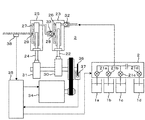
- FIG. 6 is a configuration diagram showing an outline of the configuration of the liquid delivery device.
- 3 is a liquid feeding device for a low-pressure gradient system in which a plurality of, for example, two cylinders provided with outlet-side flow paths for solvent mixing are provided so that the solvent flow directions are in series. is there.
- a chromatogram is created by changing a predetermined mixing ratio with time for a plurality of types of solvents. At a certain moment, a plurality of types of solvents are required to be well mixed and free from unevenness.
- the 6 includes a first cylinder 23 provided with a first plunger 22 and a second cylinder 25 provided with a second plunger 24.
- the first cylinder 23 and the second cylinder 25 are provided with a plurality of discharge passages 26 and 27 and merging portions 28 and 29 where the solvents discharged from the respective discharge passages merge.
- the first cylinder 23 is provided with an inlet side check valve 32 and an outlet side check valve 33.
- the rotation of the motor 34 is transmitted to the rotation of the first cam 30 and the second cam 31, and the first plunger 22 and the second plunger 24 are reciprocated by the first cam 30 and the second cam 31, respectively.
- the rotation of the motor 34 is controlled by the control device 35.
- a member 36 having a slit is attached to the rotation shafts of the first cam 30 and the second cam 31 in order to determine the position of the cam.
- the rotation sensor 37 detects the slit of the member 36, and this data is controlled.
- the position of each cam is determined by the control device 35.
- the control device 35 controls the rotation of the motor 34 based on the position of the cam and the pressure data sent from the pressure detector 38 in the discharge side flow passage that measures the discharge pressure from the second cylinder 25. Further, the control device 35 performs opening / closing control of the switching valves 21a, 21b, 21c, and 21d of the solvent switching device 2 so that the solvent mixing ratio necessary for the low pressure gradient system is obtained. These operations are performed by reading a program from a memory (not shown) and executing it by a processor (not shown) to send commands to each device. In the pipe between the solvent switching device 2 and the liquid feeding device 3, each solvent flows in the order of opening and closing of the switching valve with respect to the flow direction.
- the control device 35 opens the inlet side check valve 32 provided in the first cylinder 23, and the first plunger 22 starts the suction operation. From the inlet side check valve 32, each solvent flows in the order switched by the solvent switching device 2.
- the first cylinder 23 is filled with the solvent, the first plunger 22 is stopped and pushing in the reverse direction is started.
- the inlet side check valve 32 is closed, the outlet side check valve 33 is opened, and the solvent in the first cylinder 23 flows into the second cylinder 25.
- the first cylinder 23 is provided with a plurality of discharge passages 26 as shown in FIG. 3, and the solvent joins at the joining portion 28 and flows to the outlet side check valve 33.
- the plurality of solvents in the first cylinder 23 are mixed when the first plunger 22 is sucked and when the plurality of discharge flow paths 26 are merged at the flow merge unit 28.
- the outlet side check valve 33 is closed, and the solvent in the second cylinder 25 is shown in FIG. It flows through the plurality of discharge channels 27 as shown, passes through the junction 29, and is further mixed.
- a liquid chromatograph and a liquid chromatograph feeding device that analyze a sample while changing the mixing ratio of a plurality of solvents represented by a low pressure gradient system, mixing is performed. It is possible to provide a device that can promote the mixing of a plurality of solvents without newly adding a special device such as a vessel.
Landscapes
- Physics & Mathematics (AREA)
- Health & Medical Sciences (AREA)
- Life Sciences & Earth Sciences (AREA)
- Chemical & Material Sciences (AREA)
- Analytical Chemistry (AREA)
- Biochemistry (AREA)
- General Health & Medical Sciences (AREA)
- General Physics & Mathematics (AREA)
- Immunology (AREA)
- Pathology (AREA)
- Sampling And Sample Adjustment (AREA)
Abstract
複数の溶媒の混合比を変化させながら試料を分析する液体クロマトグラフおよび液体クロマトグラフ用送液装置において、混合器等の特別な装置を新たに付加することなく複数の溶媒の混合を促進させることを可能とする。 液体クロマトグラフ用送液装置は、その内部に複数の溶媒を流入させるシリンダと、複数の溶媒を流入させるとともに吐出して送液するために往復運動するプランジャとを備え、シリンダに複数の溶媒が混合する複数個の流路を設けた構成を有する。
Description
本発明は、液体クロマトグラフに係り、特に液体クロマトグラフ用送液装置に関する。
液体クロマトグラフは、試料を搬送するための溶媒を送液装置で送り、溶媒に試料を加えた後に分離カラムを通すことで、試料を成分毎に分離し、検出器で検出してクロマトグラムを作成し、試料の成分を分析するものである。また、液体クロマトグラフには、複数種類の溶媒を混合させるとともに、開閉弁により各溶媒の混合比を変化させながら送液装置で送液する低圧グラジエントシステムと呼ばれる送液システムが用いられるものがある。このシステムでは、複数種類の溶媒の混合比の精度をあげるために、各溶媒の容器の弁を1個ずつ順番に開けて送液する。したがって、溶媒の容器の直後の配管内は、各溶媒毎の濃度が高くなっていて混合していない。しかし、試料を導入するときに、これらの複数種類の溶媒を十分に混合させておくことができないと、分離カラムでの試料の分離が不十分になり、分析精度の低下をもたらす。したがって、例えば、配管の途中に混合器を設けて複数種類の混合を促進させる試みがなされている(例えば、特許文献1参照)。混合を促進させるためには、混合器の容量を十分に大きくする必要があり、溶媒から分離カラムまでの配管の容量が大きくなる。その結果、管内抵抗が大きくなるため、送液装置の負荷が増えるので、送液装置を大型化する必要があり、コストアップにつながる。
液体クロマトグラフの送液装置として、シリンダ内に設けられたプランジャの往復運動により溶媒の吸引と吐出を繰り返し、連続送液を行う送液装置が知られている。開閉弁によって混合される溶媒は流れ方向に対して交互に配置され、送液過程の拡散によって混合されるが、混合性能は高くない。そこで、シリンダ壁とプランジャの間の空間で混合を促進させる技術が提案されている(例えば、特許文献2参照)。
本発明は、低圧グラジエントシステムに代表される複数の溶媒の混合比を変化させながら試料を分析する液体クロマトグラフおよび液体クロマトグラフ用送液装置において、混合器等の特別な装置を新たに付加することなく複数の溶媒の混合を促進させることができる装置を提供することを目的とする。
上記課題を解決するために、本発明の実施態様は、その内部に複数の溶媒を流入させるシリンダと、複数の溶媒を流入させるとともに吐出して送液するために往復運動するプランジャとを備えた液体クロマトグラフ用送液装置であって、特に、シリンダに複数の溶媒が混合する複数個の流路を設けた構成を有することを特徴とする。
本発明によれば、低圧グラジエントシステムに代表される複数の溶媒の混合比を変化させながら試料を分析する液体クロマトグラフおよび液体クロマトグラフ用送液装置において、混合器等の特別な装置を新たに付加することなく複数の溶媒の混合を促進させることができる装置を提供することができる。
本発明の他の目的、特徴及び利点は添付図面に関する以下の本発明の実施例の記載から明らかになるであろう。
本発明の他の目的、特徴及び利点は添付図面に関する以下の本発明の実施例の記載から明らかになるであろう。
以下、図面を参照しながら本発明の実施例を説明する。
上記記載は実施例についてなされたが、本発明はそれに限らず、本発明の精神と添付の請求の範囲の範囲内で種々の変更および修正をすることができることは当業者に明らかである。
上記記載は実施例についてなされたが、本発明はそれに限らず、本発明の精神と添付の請求の範囲の範囲内で種々の変更および修正をすることができることは当業者に明らかである。
〔実施例〕
図1は、液体クロマトグラフの概要を示す構成図であり、特に、低圧グラジエントシステムの代表的な構成例を示す。低圧グラジエントシステムは、複数の溶媒容器1a,1b,1c,1dに保管された複数種類の溶媒の混合比を変化させる溶媒切換装置2と、溶媒を送液するプランジャポンプ等の送液装置3と、測定対象試料を溶媒中へ注入する試料注入装置4と、溶媒とともに送液された試料を分離する分離カラム5と、分離された試料を順に検出する検出器6と、溶媒切換装置2の切換え動作、溶媒切換装置2の弁の切換え、送液装置3の排出容量、試料注入装置4の試料注入タイミングを制御し、検出器6から送信されるデータを解析し、クロマトグラムを図示しないディスプレイへ表示する制御装置100とを備えている。
図1は、液体クロマトグラフの概要を示す構成図であり、特に、低圧グラジエントシステムの代表的な構成例を示す。低圧グラジエントシステムは、複数の溶媒容器1a,1b,1c,1dに保管された複数種類の溶媒の混合比を変化させる溶媒切換装置2と、溶媒を送液するプランジャポンプ等の送液装置3と、測定対象試料を溶媒中へ注入する試料注入装置4と、溶媒とともに送液された試料を分離する分離カラム5と、分離された試料を順に検出する検出器6と、溶媒切換装置2の切換え動作、溶媒切換装置2の弁の切換え、送液装置3の排出容量、試料注入装置4の試料注入タイミングを制御し、検出器6から送信されるデータを解析し、クロマトグラムを図示しないディスプレイへ表示する制御装置100とを備えている。
図2は、配管内の複数の溶媒の流れの状態を示す説明図である。溶媒切換装置2と送液装置3との間の配管内は、溶媒切換装置2の切換え順序に従って、図2に示すような順番で、図1に示す4種類の溶媒がそれぞれまとまって流れてくる。
図3は、送液装置のシリンダ部の構成を示す断面図であり、溶媒容器と溶媒切換装置との接続状態も示してしる。送液装置のシリンダ7の内部をプランジャ8が、モータ駆動等により往復運動し、入口側流路9と出口側流路10のそれぞれに設けられた図示しない弁機構により、入口側流路9から吸引された溶媒が出口側流路10から吐出される。制御装置100は、図2に示した溶媒切換装置2による溶媒の切換えを、プランジャ8が吸引工程のときに、全種類の溶媒について行うようにする。そして、吐出工程のときに、複数個の開口部を有している出口側流路10から、全種類の溶媒が吐出され、合流部に設けたフィルタ11で合流して送液される。この構成により、送液装置3から溶媒が吐出されるときには、複数種類の溶媒が混合された状態となっている。
図4(a)は、シリンダ7の内部空間と入口側流路13との間にフィルタ14を設け、シリンダ7の内部空間と出口側配管15との間にフィルタ16を設けた構成である。シリンダ7の耐圧力を考慮すると、フィルタの構造は、図4(b)に示したような、シリンダ7に複数個の出口側流路10を設け、それらを繋ぐ流路を形成するとともに、その流路内にフィルタ16を設け、出口側配管15が接続された流路を密閉するカバー17を設ける構造とする。入口側流路についても同様に、シリンダ7に設けた複数の流路の前側にフィルタを設ける構造とする。図2に示した溶媒切換装置2による溶媒の切換えは、プランジャ8が吸引工程のときに、全種類の溶媒について行われるようにする。溶媒がフィルタ14で混合されながらシリンダ7の内部に吸引される。そして、吐出工程のときに、図4に示すように、複数個の流路とフィルタ16通過して混合され、出口側配管15から全種類の溶媒が吐出される。この構成により、送液装置3から溶媒が吐出されるときには、複数種類の溶媒が混合された状態となっている。
図5は、送液装置のシリンダ部の構成を示す断面図であり、図3の構成と異なり、溶媒がシリンダに流入する側に複数の流路を設けた構成の一例を示している。プランジャ52の吸引動作のときに、溶媒切換装置2の切換弁が開閉して、溶媒容器1a,1b,1c,1d内の複数種類の溶媒が順番に吸引される。溶媒はシリンダ51に流入するときに入口側複数流路53を通過することにより、シリンダ51内でシリンダの径方向に混合され、プランジャ52の吐出動作のときに吐出流路54から吐出される。
図6は、送液装置の構成の概要を示す構成図である。図3に示した溶媒の混合のための出口側流路を設けたシリンダを複数個、たとえば2個を、溶媒の流れ方向が直列になるように設けた、低圧グラジエントシステム用の送液装置である。低圧グラジエントシステムでは、複数種類の溶媒を、予め決められた混合割合を時間的に変化させながら、クロマトグラムを作成するものである。そして、ある瞬間では、複数種類の溶媒は、よく混合されていてムラがないことが要求される。
図6に示す送液装置は、第1プランジャ22が設けられた第1シリンダ23と、第2プランジャ24が設けられた第2シリンダ25を備えている。第1シリンダ23と第2シリンダ25には、それぞれ複数個の吐出流路26,27と、各吐出流路から吐出された溶媒が合流する合流部28,29が設けられている。第1シリンダ23には入口側逆止弁32と出口側逆止弁33が設けられている。
モータ34の回転が第1カム30,第2カム31の回転に伝達され、第1プランジャ22,第2プランジャ24は、それぞれ第1カム30,第2カム31により往復運動する。モータ34の回転は、制御装置35により制御される。第1カム30と第2カム31の回転軸には、カムの位置を判定するために、スリットを備えた部材36が取り付けられ、回転センサ37により部材36のスリットが検知され、このデータが制御装置35へ送られ、それぞれのカムの位置が制御装置35で判定される。
制御装置35は、カムの位置と、第2シリンダ25からの吐出圧力を測定する吐出側流路内圧力検出器38から送られる圧力データとに基づき、モータ34の回転を制御する。また、制御装置35は、低圧グラジエントシステムとして必要な溶媒の混合比になるように、溶媒切換装置2の切換弁21a,21b,21c,21dの開閉制御を行う。これらの動作は、図示しないメモリからプログラムを読み出して、図示しないプロセッサが実行することで、各装置への指令が送られる。溶媒切換装置2と送液装置3との間の配管内は、各溶媒が流れ方向に対して切換弁の開閉順に流れる。
送液の開始時点では、制御装置35により、第1シリンダ23に設けられた入口側逆止弁32が開放され、第1プランジャ22が吸引動作を開始する。入口側逆止弁32からは、各溶媒が溶媒切換装置2で切換えられた順番に流入する。第1シリンダ23に溶媒が満たされると、第1プランジャ22が停止し逆方向への押し込みが開始される。第1プランジャ22の押し込みのときには、入口側逆止弁32が閉鎖され、出口側逆止弁33が開放され、第1シリンダ23内の溶媒が第2シリンダ25へ流入する。第1シリンダ23には、図3に示したような複数の吐出流路26が設けられ、溶媒が合流部28で合流して出口側逆止弁33へ流れる。第1シリンダ23内の複数の溶媒は、第1プランジャ22の吸引動作のときと、複数の吐出流路26を流れ合流部28で合流するときに混合される。第2プランジャ24の吸引動作が終了し、逆方向への押し込みが開始すると、出口側逆止弁33が閉鎖され、第2シリンダ25内の溶媒は、第2シリンダ25に設けられた図3に示したような複数の吐出流路27を流れ、合流部29を通過して、さらに混合される。
本実施例では、図3に示した複数の吐出流路を2個のシリンダに設けた例を説明したが、合流部にフィルタを設けたり、図4に示したフィルタで混合させる構造のシリンダを用いても、溶媒を混合させることができる。また、図5に示した入口側に複数流路を設けた構造のシリンダを用いても、溶媒を混合させることができる。また、2個のシリンダを、溶媒の流れ方向が並列になるように並べた構成の液体クロマトグラフ用送液装置でも、図3,図4,図5に示した構成を採用することで、溶媒の混合を促進させることができる。
以上述べたように、本発明の実施例によれば、低圧グラジエントシステムに代表される複数の溶媒の混合比を変化させながら試料を分析する液体クロマトグラフおよび液体クロマトグラフ用送液装置において、混合器等の特別な装置を新たに付加することなく複数の溶媒の混合を促進させることができる装置を提供することができる。
2 溶媒切換装置
3 送液装置
7,51 シリンダ
8,52 プランジャ
9,13 入口側流路
10 出口側流路
11,14,16 フィルタ
12,15 出口側配管
17 カバー
22 第1プランジャ
23 第1シリンダ
24 第2プランジャ
25 第2シリンダ
32 入口側逆止弁
33 出口側逆止弁
53 入口側複数流路
54 吐出流路
3 送液装置
7,51 シリンダ
8,52 プランジャ
9,13 入口側流路
10 出口側流路
11,14,16 フィルタ
12,15 出口側配管
17 カバー
22 第1プランジャ
23 第1シリンダ
24 第2プランジャ
25 第2シリンダ
32 入口側逆止弁
33 出口側逆止弁
53 入口側複数流路
54 吐出流路
Claims (12)
- 複数の溶媒の混合比を変化させながら試料を導入し、分離カラムで前記試料を分離して成分を検出する液体クロマトグラフにおいて、
前記複数の溶媒を前記分離カラムへ送液する送液装置を備え、
該送液装置は、その内部に前記複数の溶媒を流入させるシリンダと、前記複数の溶媒を流入させるとともに吐出して送液するために往復運動するプランジャと、前記複数の溶媒が混合する複数個の流路とを有することを特徴とする液体クロマトグラフ。 - 請求項1の記載において、前記複数個の流路は、前記複数の溶媒が前記シリンダから吐出する側に設けられていることを特徴とする液体クロマトグラフ。
- 請求項2の記載において、前記複数の流路の後流側に合流部が設けられていることを特徴とする液体クロマトグラフ。
- 請求項2の記載において、前記複数の流路の後流側にフィルタが設けられていることを特徴とする液体クロマトグラフ。
- 請求項1の記載において、前記複数個の流路は、前記複数の溶媒が前記シリンダに流入する側に設けられていることを特徴とする液体クロマトグラフ。
- 請求項5の記載において、前記複数の流路の前側にフィルタが設けられていることを特徴とする液体クロマトグラフ。
- 複数の溶媒を分離カラムへ送液する液体クロマトグラフ用送液装置において、
その内部に前記複数の溶媒を流入させるシリンダと、前記複数の溶媒を流入させるとともに吐出して送液するために往復運動するプランジャと、前記複数の溶媒が混合する複数個の流路とを有することを特徴とする液体クロマトグラフ用送液装置。 - 請求項7の記載において、前記複数個の流路は、前記複数の溶媒が前記シリンダから吐出する側に設けられていることを特徴とする液体クロマトグラフ用送液装置。
- 請求項8の記載において、前記複数の流路の後流側に合流部が設けられていることを特徴とする液体クロマトグラフ用送液装置。
- 請求項8の記載において、前記複数の流路の後流側にフィルタが設けられていることを特徴とする液体クロマトグラフ用送液装置。
- 請求項7の記載において、前記複数個の流路は、前記複数の溶媒が前記シリンダに流入する側に設けられていることを特徴とする液体クロマトグラフ用送液装置。
- 請求項11の記載において、前記複数の流路の前側にフィルタが設けられていることを特徴とする液体クロマトグラフ用送液装置。
Priority Applications (1)
| Application Number | Priority Date | Filing Date | Title |
|---|---|---|---|
| US13/805,337 US20130091935A1 (en) | 2010-07-06 | 2011-07-05 | Liquid chromatograph and pump unit for liquid chromatograph |
Applications Claiming Priority (2)
| Application Number | Priority Date | Filing Date | Title |
|---|---|---|---|
| JP2010-153538 | 2010-07-06 | ||
| JP2010153538A JP2012017985A (ja) | 2010-07-06 | 2010-07-06 | 液体クロマトグラフ、および液体クロマトグラフ用送液装置 |
Publications (1)
| Publication Number | Publication Date |
|---|---|
| WO2012005233A1 true WO2012005233A1 (ja) | 2012-01-12 |
Family
ID=45441212
Family Applications (1)
| Application Number | Title | Priority Date | Filing Date |
|---|---|---|---|
| PCT/JP2011/065327 Ceased WO2012005233A1 (ja) | 2010-07-06 | 2011-07-05 | 液体クロマトグラフ、および液体クロマトグラフ用送液装置 |
Country Status (3)
| Country | Link |
|---|---|
| US (1) | US20130091935A1 (ja) |
| JP (1) | JP2012017985A (ja) |
| WO (1) | WO2012005233A1 (ja) |
Families Citing this family (4)
| Publication number | Priority date | Publication date | Assignee | Title |
|---|---|---|---|---|
| JP6055720B2 (ja) * | 2013-05-27 | 2016-12-27 | 株式会社日立ハイテクノロジーズ | 液体クロマトグラフ |
| DE102013212740A1 (de) | 2013-06-28 | 2014-12-31 | Agilent Technologies, Inc. | Hplc-pumpe mit tangentialer einströmung in die pumpkammer |
| CN105339660B (zh) * | 2013-06-28 | 2019-08-09 | 安捷伦科技有限公司 | 带有与泵送室中的不同空间位置相联的出口的泵送设备 |
| DE102013218818A1 (de) | 2013-09-19 | 2015-03-19 | Agilent Technologies, Inc. - A Delaware Corporation - | HPLC-Pumpe mit aktivem Mischelement |
Citations (3)
| Publication number | Priority date | Publication date | Assignee | Title |
|---|---|---|---|---|
| JPS61258975A (ja) * | 1985-05-10 | 1986-11-17 | Hitachi Ltd | 液体クロマトグラフ用定量ポンプ |
| JPH0736057U (ja) * | 1991-07-23 | 1995-07-04 | 日本分光株式会社 | Hplc用ポンプ |
| JP2006250835A (ja) * | 2005-03-14 | 2006-09-21 | Shimadzu Corp | 液体クロマトグラフ用送液ポンプ |
Family Cites Families (7)
| Publication number | Priority date | Publication date | Assignee | Title |
|---|---|---|---|---|
| US6997683B2 (en) * | 2003-01-10 | 2006-02-14 | Teledyne Isco, Inc. | High pressure reciprocating pump and control of the same |
| US7147364B2 (en) * | 2003-09-29 | 2006-12-12 | Hitachi High-Technologies Corporation | Mixer and liquid analyzer provided with same |
| JP4511578B2 (ja) * | 2007-08-28 | 2010-07-28 | 株式会社日立ハイテクノロジーズ | 送液装置、液体クロマトグラフ、および送液装置の運転方法 |
| JP5155937B2 (ja) * | 2009-05-26 | 2013-03-06 | 株式会社日立ハイテクノロジーズ | 送液装置および液体クロマトグラフ装置 |
| JP5358334B2 (ja) * | 2009-07-28 | 2013-12-04 | 株式会社日立ハイテクノロジーズ | 逆止弁を用いた送液装置、および反応液体クロマトグラフシステム |
| JPWO2011090188A1 (ja) * | 2010-01-25 | 2013-05-23 | 株式会社日立ハイテクノロジーズ | 液体クロマトグラフ、および液体クロマトグラフ用送液装置 |
| US20120204626A1 (en) * | 2010-08-13 | 2012-08-16 | Davison Dale A | Sample injector for liquid chromatograph |
-
2010
- 2010-07-06 JP JP2010153538A patent/JP2012017985A/ja active Pending
-
2011
- 2011-07-05 WO PCT/JP2011/065327 patent/WO2012005233A1/ja not_active Ceased
- 2011-07-05 US US13/805,337 patent/US20130091935A1/en not_active Abandoned
Patent Citations (3)
| Publication number | Priority date | Publication date | Assignee | Title |
|---|---|---|---|---|
| JPS61258975A (ja) * | 1985-05-10 | 1986-11-17 | Hitachi Ltd | 液体クロマトグラフ用定量ポンプ |
| JPH0736057U (ja) * | 1991-07-23 | 1995-07-04 | 日本分光株式会社 | Hplc用ポンプ |
| JP2006250835A (ja) * | 2005-03-14 | 2006-09-21 | Shimadzu Corp | 液体クロマトグラフ用送液ポンプ |
Also Published As
| Publication number | Publication date |
|---|---|
| JP2012017985A (ja) | 2012-01-26 |
| US20130091935A1 (en) | 2013-04-18 |
Similar Documents
| Publication | Publication Date | Title |
|---|---|---|
| US8522627B2 (en) | Automatic sampler for liquid chromatograph | |
| CN105745535B (zh) | 用于样品分析仪的梯度液体输送装置 | |
| EP2990791B1 (en) | Switching valve for a flow-type analysis device | |
| US9983177B2 (en) | Autosampler and liquid chromatograph | |
| US9833754B2 (en) | Sample dilution to specifiable dilution ratio | |
| US11009488B2 (en) | Fluid chromatograph | |
| WO2011090188A1 (ja) | 液体クロマトグラフ、および液体クロマトグラフ用送液装置 | |
| CN108956788A (zh) | 用于多维液体分析的阀和分流系统 | |
| US20110290042A1 (en) | Liquid Sample Injection Device and Liquid Sample Injection Method | |
| WO2019229819A1 (ja) | 自動試料導入装置、クロマトグラフ、自動試料導入方法および分析方法 | |
| CN105264370B (zh) | 流式分析设备的样本注入装置、流式分析设备及血红蛋白成分的测量方法 | |
| JP2015092166A5 (ja) | ||
| JP2012017985A (ja) | 液体クロマトグラフ、および液体クロマトグラフ用送液装置 | |
| JP6672781B2 (ja) | 流路機構及びこれを備えた液体クロマトグラフ | |
| JP2012247440A (ja) | 液体試料分析装置及び液体試料導入装置 | |
| US12140575B2 (en) | Branching off fluidic sample with low influence on source flow path | |
| US12589329B2 (en) | Fluid separation with sampling unit selectively coupling upstream and downstream of separation unit | |
| JP2012086136A (ja) | 液体混合装置及びその液体混合装置を用いた液体混合方法 | |
| CN113167774B (zh) | 从移动相中移除不确定组合物部分 | |
| JP2006118374A (ja) | 送液システム | |
| CN105339660A (zh) | 带有与泵送室中的不同空间位置相联的出口的泵送设备 |
Legal Events
| Date | Code | Title | Description |
|---|---|---|---|
| 121 | Ep: the epo has been informed by wipo that ep was designated in this application |
Ref document number: 11803567 Country of ref document: EP Kind code of ref document: A1 |
|
| WWE | Wipo information: entry into national phase |
Ref document number: 13805337 Country of ref document: US |
|
| NENP | Non-entry into the national phase |
Ref country code: DE |
|
| 122 | Ep: pct application non-entry in european phase |
Ref document number: 11803567 Country of ref document: EP Kind code of ref document: A1 |