WO2012004643A1 - 省電力支援コントローラ、および省電力支援システム - Google Patents
省電力支援コントローラ、および省電力支援システム Download PDFInfo
- Publication number
- WO2012004643A1 WO2012004643A1 PCT/IB2011/001315 IB2011001315W WO2012004643A1 WO 2012004643 A1 WO2012004643 A1 WO 2012004643A1 IB 2011001315 W IB2011001315 W IB 2011001315W WO 2012004643 A1 WO2012004643 A1 WO 2012004643A1
- Authority
- WO
- WIPO (PCT)
- Prior art keywords
- unit
- power
- time
- occurrence
- unit price
- Prior art date
- Legal status (The legal status is an assumption and is not a legal conclusion. Google has not performed a legal analysis and makes no representation as to the accuracy of the status listed.)
- Ceased
Links
Images






Classifications
-
- G—PHYSICS
- G06—COMPUTING OR CALCULATING; COUNTING
- G06Q—INFORMATION AND COMMUNICATION TECHNOLOGY [ICT] SPECIALLY ADAPTED FOR ADMINISTRATIVE, COMMERCIAL, FINANCIAL, MANAGERIAL OR SUPERVISORY PURPOSES; SYSTEMS OR METHODS SPECIALLY ADAPTED FOR ADMINISTRATIVE, COMMERCIAL, FINANCIAL, MANAGERIAL OR SUPERVISORY PURPOSES, NOT OTHERWISE PROVIDED FOR
- G06Q10/00—Administration; Management
- G06Q10/06—Resources, workflows, human or project management; Enterprise or organisation planning; Enterprise or organisation modelling
-
- G—PHYSICS
- G06—COMPUTING OR CALCULATING; COUNTING
- G06Q—INFORMATION AND COMMUNICATION TECHNOLOGY [ICT] SPECIALLY ADAPTED FOR ADMINISTRATIVE, COMMERCIAL, FINANCIAL, MANAGERIAL OR SUPERVISORY PURPOSES; SYSTEMS OR METHODS SPECIALLY ADAPTED FOR ADMINISTRATIVE, COMMERCIAL, FINANCIAL, MANAGERIAL OR SUPERVISORY PURPOSES, NOT OTHERWISE PROVIDED FOR
- G06Q30/00—Commerce
- G06Q30/04—Billing or invoicing
-
- H—ELECTRICITY
- H02—GENERATION; CONVERSION OR DISTRIBUTION OF ELECTRIC POWER
- H02J—ELECTRIC POWER NETWORKS; CIRCUIT ARRANGEMENTS OR SYSTEMS FOR SUPPLYING OR DISTRIBUTING ELECTRIC POWER; SYSTEMS FOR STORING ELECTRIC ENERGY
- H02J3/00—Circuit arrangements for AC mains or AC distribution networks
- H02J3/12—Arrangements for adjusting voltage in AC networks by changing a characteristic of the network load
- H02J3/14—Arrangements for adjusting voltage in AC networks by changing a characteristic of the network load by switching loads on to, or off from, the networks, e.g. progressively balanced loading
-
- H—ELECTRICITY
- H02—GENERATION; CONVERSION OR DISTRIBUTION OF ELECTRIC POWER
- H02J—ELECTRIC POWER NETWORKS; CIRCUIT ARRANGEMENTS OR SYSTEMS FOR SUPPLYING OR DISTRIBUTING ELECTRIC POWER; SYSTEMS FOR STORING ELECTRIC ENERGY
- H02J2105/00—Networks for supplying or distributing electric power characterised by their spatial reach or by the load
- H02J2105/40—Networks for supplying or distributing electric power characterised by their spatial reach or by the load characterised by the loads connecting to the networks or being supplied by the networks
- H02J2105/42—Home appliances
-
- H—ELECTRICITY
- H02—GENERATION; CONVERSION OR DISTRIBUTION OF ELECTRIC POWER
- H02J—ELECTRIC POWER NETWORKS; CIRCUIT ARRANGEMENTS OR SYSTEMS FOR SUPPLYING OR DISTRIBUTING ELECTRIC POWER; SYSTEMS FOR STORING ELECTRIC ENERGY
- H02J2105/00—Networks for supplying or distributing electric power characterised by their spatial reach or by the load
- H02J2105/50—Networks for supplying or distributing electric power characterised by their spatial reach or by the load for selectively controlling the operation of the loads
- H02J2105/54—Networks for supplying or distributing electric power characterised by their spatial reach or by the load for selectively controlling the operation of the loads according to a non-electrical condition, e.g. temperature
- H02J2105/55—Networks for supplying or distributing electric power characterised by their spatial reach or by the load for selectively controlling the operation of the loads according to a non-electrical condition, e.g. temperature according to an economic condition, e.g. tariff-based load management
-
- Y—GENERAL TAGGING OF NEW TECHNOLOGICAL DEVELOPMENTS; GENERAL TAGGING OF CROSS-SECTIONAL TECHNOLOGIES SPANNING OVER SEVERAL SECTIONS OF THE IPC; TECHNICAL SUBJECTS COVERED BY FORMER USPC CROSS-REFERENCE ART COLLECTIONS [XRACs] AND DIGESTS
- Y02—TECHNOLOGIES OR APPLICATIONS FOR MITIGATION OR ADAPTATION AGAINST CLIMATE CHANGE
- Y02B—CLIMATE CHANGE MITIGATION TECHNOLOGIES RELATED TO BUILDINGS, e.g. HOUSING, HOUSE APPLIANCES OR RELATED END-USER APPLICATIONS
- Y02B70/00—Technologies for an efficient end-user side electric power management and consumption
- Y02B70/30—Systems integrating technologies related to power network operation and communication or information technologies for improving the carbon footprint of the management of residential or tertiary loads, i.e. smart grids as climate change mitigation technology in the buildings sector, including also the last stages of power distribution and the control, monitoring or operating management systems at local level
-
- Y—GENERAL TAGGING OF NEW TECHNOLOGICAL DEVELOPMENTS; GENERAL TAGGING OF CROSS-SECTIONAL TECHNOLOGIES SPANNING OVER SEVERAL SECTIONS OF THE IPC; TECHNICAL SUBJECTS COVERED BY FORMER USPC CROSS-REFERENCE ART COLLECTIONS [XRACs] AND DIGESTS
- Y02—TECHNOLOGIES OR APPLICATIONS FOR MITIGATION OR ADAPTATION AGAINST CLIMATE CHANGE
- Y02B—CLIMATE CHANGE MITIGATION TECHNOLOGIES RELATED TO BUILDINGS, e.g. HOUSING, HOUSE APPLIANCES OR RELATED END-USER APPLICATIONS
- Y02B70/00—Technologies for an efficient end-user side electric power management and consumption
- Y02B70/30—Systems integrating technologies related to power network operation and communication or information technologies for improving the carbon footprint of the management of residential or tertiary loads, i.e. smart grids as climate change mitigation technology in the buildings sector, including also the last stages of power distribution and the control, monitoring or operating management systems at local level
- Y02B70/3225—Demand response systems, e.g. load shedding, peak shaving
-
- Y—GENERAL TAGGING OF NEW TECHNOLOGICAL DEVELOPMENTS; GENERAL TAGGING OF CROSS-SECTIONAL TECHNOLOGIES SPANNING OVER SEVERAL SECTIONS OF THE IPC; TECHNICAL SUBJECTS COVERED BY FORMER USPC CROSS-REFERENCE ART COLLECTIONS [XRACs] AND DIGESTS
- Y04—INFORMATION OR COMMUNICATION TECHNOLOGIES HAVING AN IMPACT ON OTHER TECHNOLOGY AREAS
- Y04S—SYSTEMS INTEGRATING TECHNOLOGIES RELATED TO POWER NETWORK OPERATION, COMMUNICATION OR INFORMATION TECHNOLOGIES FOR IMPROVING THE ELECTRICAL POWER GENERATION, TRANSMISSION, DISTRIBUTION, MANAGEMENT OR USAGE, i.e. SMART GRIDS
- Y04S20/00—Management or operation of end-user stationary applications or the last stages of power distribution; Controlling, monitoring or operating thereof
- Y04S20/20—End-user application control systems
- Y04S20/222—Demand response systems, e.g. load shedding, peak shaving
-
- Y—GENERAL TAGGING OF NEW TECHNOLOGICAL DEVELOPMENTS; GENERAL TAGGING OF CROSS-SECTIONAL TECHNOLOGIES SPANNING OVER SEVERAL SECTIONS OF THE IPC; TECHNICAL SUBJECTS COVERED BY FORMER USPC CROSS-REFERENCE ART COLLECTIONS [XRACs] AND DIGESTS
- Y04—INFORMATION OR COMMUNICATION TECHNOLOGIES HAVING AN IMPACT ON OTHER TECHNOLOGY AREAS
- Y04S—SYSTEMS INTEGRATING TECHNOLOGIES RELATED TO POWER NETWORK OPERATION, COMMUNICATION OR INFORMATION TECHNOLOGIES FOR IMPROVING THE ELECTRICAL POWER GENERATION, TRANSMISSION, DISTRIBUTION, MANAGEMENT OR USAGE, i.e. SMART GRIDS
- Y04S20/00—Management or operation of end-user stationary applications or the last stages of power distribution; Controlling, monitoring or operating thereof
- Y04S20/20—End-user application control systems
- Y04S20/242—Home appliances
-
- Y—GENERAL TAGGING OF NEW TECHNOLOGICAL DEVELOPMENTS; GENERAL TAGGING OF CROSS-SECTIONAL TECHNOLOGIES SPANNING OVER SEVERAL SECTIONS OF THE IPC; TECHNICAL SUBJECTS COVERED BY FORMER USPC CROSS-REFERENCE ART COLLECTIONS [XRACs] AND DIGESTS
- Y04—INFORMATION OR COMMUNICATION TECHNOLOGIES HAVING AN IMPACT ON OTHER TECHNOLOGY AREAS
- Y04S—SYSTEMS INTEGRATING TECHNOLOGIES RELATED TO POWER NETWORK OPERATION, COMMUNICATION OR INFORMATION TECHNOLOGIES FOR IMPROVING THE ELECTRICAL POWER GENERATION, TRANSMISSION, DISTRIBUTION, MANAGEMENT OR USAGE, i.e. SMART GRIDS
- Y04S50/00—Market activities related to the operation of systems integrating technologies related to power network operation or related to communication or information technologies
- Y04S50/10—Energy trading, including energy flowing from end-user application to grid
-
- Y—GENERAL TAGGING OF NEW TECHNOLOGICAL DEVELOPMENTS; GENERAL TAGGING OF CROSS-SECTIONAL TECHNOLOGIES SPANNING OVER SEVERAL SECTIONS OF THE IPC; TECHNICAL SUBJECTS COVERED BY FORMER USPC CROSS-REFERENCE ART COLLECTIONS [XRACs] AND DIGESTS
- Y04—INFORMATION OR COMMUNICATION TECHNOLOGIES HAVING AN IMPACT ON OTHER TECHNOLOGY AREAS
- Y04S—SYSTEMS INTEGRATING TECHNOLOGIES RELATED TO POWER NETWORK OPERATION, COMMUNICATION OR INFORMATION TECHNOLOGIES FOR IMPROVING THE ELECTRICAL POWER GENERATION, TRANSMISSION, DISTRIBUTION, MANAGEMENT OR USAGE, i.e. SMART GRIDS
- Y04S50/00—Market activities related to the operation of systems integrating technologies related to power network operation or related to communication or information technologies
- Y04S50/12—Billing, invoicing, buying or selling transactions or other related activities, e.g. cost or usage evaluation
Definitions
- the present invention relates to a power saving support controller and a power saving support system.
- the unit price of electricity charges varies depending on the time zone, and the unit price of electricity charges during night hours (for example, from 23:00 to 7:00) is lower than the unit price of electricity charges during the daytime hours (for example, from 7:00 to 23:00). Is set.
- the unit price of electricity charges in each time zone is the highest daytime, the intermediate living time, and the cheapest nighttime.
- the power company can achieve leveling of the power load. That is, there are advantages for both users and electric power companies by using electric devices in a time zone where the unit price of electricity is low.
- the usage of electric devices by users tends to become habitual, and once a habit of using a specific electric device in a time zone with a high unit price is established, the user tends to use it in a time unit with a low unit price. It was difficult to change.
- the conventional system has a function to display the electricity usage of main power, branch power, etc. to the user, it is considered that the user's habits will be improved in the direction of using the electric equipment in a time zone where the electricity unit price is cheap. I did not.
- the present invention has been made in view of the above reasons, and includes a power saving support controller and a power saving support system that can improve a user's habits in a direction of using an electric device in a time zone where the unit price of electricity is low.
- the power saving support controller includes a power information acquisition unit that acquires information on power used for measurement, and a unit price acquisition unit that acquires unit price information indicating a unit price of electricity charges for each time zone. Based on the threshold setting unit for setting the threshold of the amount of power used per unit period, the time change of the amount of used power and the unit price information, the occurrence of an excess usage state in which the amount of power used exceeds the threshold.
- a usage state monitoring unit for notifying the occurrence of this excessive usage state when detected, wherein the usage state monitoring unit sets the threshold value for the amount of power used during a time period when the electricity bill is higher than in other time periods.
- the power saving support controller generates image data for generating and outputting image data for displaying on the same screen as the unit price information the time change of the power consumption per unit period derived based on the information on the power consumption to be measured A section.
- the power saving support controller further includes a power estimation unit that estimates a future power consumption amount per unit period based on the information on the power usage of the measurement target, and the unit price acquisition unit stores the future unit price information.
- the image generation unit generates and outputs image data to be displayed on the same screen as the future unit price information
- the usage state monitoring unit includes: Based on the time change of the estimated power consumption and the future unit price information, the estimated power consumption exceeds the threshold in a future time zone where the electricity bill is higher than other time zones. When the occurrence of a state is predicted, the occurrence of this overuse state may be notified.
- the threshold value setting unit may set the threshold value as a result of adding a predetermined value to the average value of the electric energy used per unit period in a time zone in which the unit price of the electricity bill is a predetermined value.
- the threshold setting unit sets a result obtained by adding a predetermined value to the average value of the electric energy used per unit period in a time zone in which the unit price of the electricity bill is higher than in other time zones. Is also possible. Further, the threshold setting unit sets a result obtained by adding a predetermined value to the average value of the electric energy used per unit period in a time zone in which the unit price of the electricity bill is lower than in other time zones. It is also possible to do.
- the threshold setting unit uses the unit per unit period in a time zone where the unit price of the electricity bill is cheaper than other time zones when the number of times the occurrence of the excess usage state is reported in a certain period is less than a predetermined number of times.
- the use state monitoring unit When the occurrence of the overuse state is detected on the previous day, the use state monitoring unit notifies the occurrence of the overuse state on the same day, a predetermined time before the time when the overuse state occurs on the previous day. It is also possible to decide. In addition, when the use state monitoring unit detects the occurrence of the overuse state, the use state monitoring unit notifies the occurrence of the overuse state a predetermined time before the time zone in which the unit price of the electricity bill is cheaper than other time zones. It is also possible to make it.
- a power saving support system includes a power measuring unit that measures power used by a measurement target, a display unit that displays image data, a notification unit that performs a notification operation, and a power saving support controller of the present invention.
- FIG. 1 is a block diagram showing a configuration of a power saving support controller and a power saving support system according to Embodiment 1 of the present invention.
- FIG. 2 is a diagram illustrating charge unit price information.
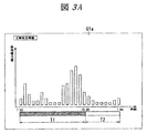
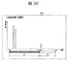
- FIGS. 3A and 3B are diagrams illustrating examples of usage status screens in the first embodiment.
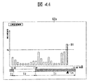
- FIG. 4 is a diagram illustrating a monitoring screen in the first embodiment.
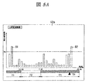
- FIGS. 5A and 5B are diagrams illustrating another monitoring screen in the first embodiment.
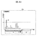
- 6A and 6B are diagrams illustrating another monitoring screen in the first embodiment.
- FIG. 7 is a block diagram showing a configuration of a power saving support controller according to Embodiment 2 of the present invention.
- FIG. 8A and 8B FIG. 8 is a diagram illustrating a prediction screen in the second embodiment.
- FIG. 1 shows a configuration of a power saving support system using the power saving support controller of the present embodiment, and includes a power measurement unit 1, a power saving support controller 2 (hereinafter referred to as controller 2), and a display 3 (display). And the notification unit) are provided in the house where the user lives.
- a distribution board 4 is installed in the house, and the distribution board 4 has a main breaker 4a receiving the commercial power AC supplied from the outside to the house on the primary side, and an electric circuit branched from the secondary side of the main breaker 4a A plurality of branch breakers 4b respectively inserted in are housed.
- Each branch electric circuit in which the branch breaker 4b is inserted is connected to an electric device X such as a water heater, a washing machine, a cooker, and an air conditioner.
- the electric power measurement unit 1 is arrange
- the main power and branch power usage data measured by the power measurement unit 1 are periodically transmitted to the controller 2 by radio.
- the controller 2 includes a wireless communication unit 2a, a network communication unit 2b, a power history storage unit 2c, a unit price acquisition unit 2d, a threshold setting unit 2e, an image generation unit 2f, and a usage state monitoring unit 2g. .
- the wireless communication unit 2 a performs wireless communication between the power measurement unit 1 and the display device 3.
- the used power data transmitted from the power measurement unit 1 is also received by the wireless communication unit 2a and stored in the power history storage unit 2c.
- the wireless communication unit 2a corresponds to the power information acquisition unit of the present invention.
- the network communication unit 2b is connected to the Internet NT via the router 5, and performs network communication with a center server SV of an electric power company installed outside the house.
- the power history storage unit 2c stores the used power data received from the power measurement unit 1 by the wireless communication unit 2a as a history of main power and branch power.
- the unit price acquisition unit 2d acquires, from the center server SV of the electric power company, information on the unit price for which the house is contracted (unit price information) through the network communication unit 2b. This unit price information shows the unit price of the electricity rate for each time zone. As shown in FIG. 2, the unit price of the electricity rate in the night time zone T2 (for example, 23:00 to 7:00) is the daytime time zone T1 (for example, It is set cheaper than the unit price of electricity charges from 7:00 to 23:00.
- the threshold value setting unit 2e has a function of setting each threshold value of the main power amount and the branch power amount in units of one hour, and this threshold value represents a target upper limit value of the main power amount and the branch power amount, and will be described later in use state Used for the monitoring operation of the monitoring unit 2g.
- the image generation unit 2f derives a temporal change in the amount of power used per unit period (1 hour) based on the history of the power used (main power or branch power). Then, image data of the usage status screen G1 for displaying the derived temporal change in the amount of power used per hour on the same screen as the unit price information is generated.
- the usage status screen G1 includes a master status screen G1a (FIG. 3A) showing the usage status of the main power, and a branch status screen G1b (FIG. 3B) showing the usage status of the branch power for each electrical device X (each branch circuit).
- the branch status screen G1b is created for each electrical device X whose status is to be confirmed.
- the image data of the usage status screen G1 (G1a, G1b) is transmitted to the display 3 via the wireless communication unit 2a.
- the display 3 displays a usage status screen G1 on the screen based on the image data received from the image generation unit 2f.
- the user can grasp the power usage status in each of the daytime time zone T1 and the nighttime time zone T2 by looking at the usage status screen G1. For example, by looking at the master status screen G1a showing the usage status of the main power, it is possible to grasp the power used in the entire house during the daytime period T1 where the unit price of electricity is high.
- the power used in the daytime period T1 where the unit price of electricity is high can be grasped for each electric device X.
- the timing at which the display 3 displays the usage status screen G1 is determined when the user operates the display 3 to acquire and display a desired usage status screen G1 from the controller 2 or at a predetermined time. May automatically obtain and display a desired usage status screen G1 from the controller 2.
- the usage state monitoring unit 2g has a function of detecting the occurrence of an excessive usage state in which the power is excessively used during the daytime period T1 where the electricity unit price is high.
- the usage status monitoring unit 2g that has detected the excessive usage status causes the image generation unit 2f to create a monitoring screen G2.
- 4A and 4B show a configuration example of the monitoring screen G2, and information on the threshold value K is added to the usage status screen G1 (see FIGS. 3A and 3B), and the bar B1 of the electric energy exceeding the threshold value K in the daytime time zone T1. Is displayed in a different color from other bars (shown as dots in FIGS. 4A and 4B).
- the monitoring screen G2 includes a master monitoring screen G2a (FIG.
- the branch monitoring screen G2b is created for each electric device X to be monitored.
- the threshold for the main power is expressed as Ka
- the threshold for the branch power is expressed as Kb.
- the creation timing of the monitoring screen G2 is set to one of the following. The first creation timing creates the monitoring screen G2 every time when the current power amount exceeds the threshold value K during the daytime period T1 and the occurrence of the excessive usage state is detected.
- the second creation timing is that when an occurrence of an overuse condition is detected in the daytime time zone T1 of the previous day, on the same day, a certain time before the same time as the occurrence of the overuse condition on the previous day (for example, one hour before)
- the monitoring screen G2 is created.
- the third creation timing when the electric energy exceeds the threshold value K during the daytime period T1, the monitoring screen G2 is created a certain time before the start time of the next nighttime period T2 (for example, one hour before).
- the image data of the monitoring screen G2 (G2a, G2b) generated at each timing is transmitted to the display 3 via the wireless communication unit 2a.
- the display 3 displays the monitoring screen G2 on the screen based on the image data received from the image generation unit 2f.
- the user By viewing the monitoring screen G2, the user is notified that an excessive usage state has occurred in the daytime time zone T1.
- the monitor screen G2 is displayed on the display 3, and the user is presented with the occurrence of the overuse state in real time. Therefore, the user is urged to shift the usage time zone of the electrical device X currently used to the night time zone T2 where the unit price of electricity is low, which provides an opportunity to improve the usage mode of the electrical device X.
- the main monitoring screen G2a at this time is shown in FIG. 4A, the branch monitoring screen G2b is shown in FIG. 4B, and the current time tn is indicated by ⁇ .
- a monitoring screen G2 from the previous day to the current day is displayed on the display 3 a certain time before the same time as the time when the excessive usage state occurred on the previous day, and the user has an excessive usage state.
- the time at which there is a high possibility of being approached the occurrence of an overuse state is presented in advance.
- the bar B2 of the amount of power exceeding the threshold value K is displayed at the same time as the time when the excessive usage state occurred on the previous day. Therefore, the user is urged to shift the usage time zone of the electrical device X that is scheduled to be used to the night time zone T2 where the unit price of electricity is low, which provides an opportunity to improve the usage pattern of the electrical device X.
- the main monitoring screen G2a at this time is shown in FIG. 5A
- the branch monitoring screen G2b is shown in FIG. 5B
- the current time tn is indicated by ⁇ .
- the monitoring screen G2 is displayed on the display 3 a certain time before the start time of the next nighttime period T2. That is, the user is presented with the occurrence of an overuse condition when the night time zone T2 where the unit price of electricity is cheaper approaches. Therefore, the user is urged to shift the use time zone of the electric device X used in the daytime time zone T1 to the night time zone T2 starting from now, which is an opportunity to improve the usage pattern of the electric device X. .
- the main monitoring screen G2a at this time is shown in FIG. 6A
- the branch monitoring screen G2b is shown in FIG. 6B
- the current time tn is indicated by ⁇ .
- a user who sees such a monitoring screen G2 and is told that he / she uses too much power during the daytime period T1 where the unit price of electricity is high uses the electric device X during the nighttime period T2 where the unit price of electricity is low.
- Awareness to improve habits in the direction is raised.
- the power company can achieve leveling of the power load.
- the threshold value setting unit 2e refers to the power history storage unit 2c, and uses every hour used in the daytime period T1 where the unit price of electricity is high in a predetermined period (for example, the past one week). Power consumption (main power and branch power) is calculated. And the average value of the electric power consumption for every hour in this predetermined period is calculated, and the result of adding a constant value to this average value is set as the threshold value K (Ka, Kb).
- the threshold value K according to the first threshold value setting method is set to a relatively high value, and is suitable for a case where it is customary to use the electric device X in the daytime period T1 where the unit price of electricity is high as a usage form of the electric device X by the user. ing. Further, by adding a constant value to the average value, only a state in which the amount of power used is prominent and higher than usual is detected as an overuse state, and frequent detection of the overuse state is suppressed.
- the threshold value setting unit 2e refers to the power history storage unit 2c, and is used for the night time period T2 where the unit price of electricity is low in a predetermined period (for example, the past one week).
- the amount of power used (main power amount and branch power amount) is calculated for each. And the average value of the electric power consumption for every hour in this predetermined period is calculated, and the result of adding a constant value to this average value is set as the threshold value K (Ka, Kb).
- the threshold value K by the second threshold value setting method is set to a relatively low value, and is suitable for a case where the user uses the electric device X as a usage pattern and is improved in the direction of use in the night time zone T2 where the unit price of electricity is low. Yes.
- the result of adding a constant value to the average value of the power consumption during the time zone where the unit price is low is set as a threshold, thereby suppressing the inability to detect overuse.
- the third threshold value setting method is a combination of the first and second threshold value setting methods. Specifically, immediately after the installation of this system, it is customary to use the device in the daytime period T1 where the unit price of electricity is high, as a usage form of the electric device X by the user. Therefore, a relatively high threshold value K is set by the first threshold value setting method. And if it improves to the direction of using in the night time slot
- FIG. 7 shows the configuration of the power saving support controller 2 (hereinafter referred to as the controller 2) of the present embodiment.
- the controller 2h By including the power estimation unit 2h, the future power consumption (main power amount and branch power amount) can be calculated.
- unit price information is stored in the center server SV of the electric power company so that it can be downloaded, and this unit price information is updated at a predetermined timing even for the same house and the same contract. This is due to a fee system in which the unit prices for weekdays and weekends are different from each other, a fee system in which the unit prices are different for each day, or the like.
- the center server SV stores not only unit price information from the past to today but also unit price information for the future (for example, until tomorrow or after one week) so that it can be downloaded.
- the unit price acquisition unit 2d acquires the unit price information for the next day from the center server SV via the network communication unit 2b at a fixed time every day.
- the power estimation unit 2h estimates the power consumption (main power amount and branch power amount) for the next day based on the main power and branch power history stored in the power history storage unit 2c. For example, the average value of the power consumption at each time (one hour unit) in the past week is estimated as the power consumption at each time (one hour unit) on the next day. Or, distinguish the past week into weekdays and holidays, and use the average value of power consumption at each time (1 hour unit) on weekdays or holidays to use each time (1 hour unit) tomorrow (weekdays or holidays). Estimated as electric energy.
- the average value of the power consumption at each time (one hour unit) on the same day of the past month is estimated as the power consumption at each time (one hour unit) on the next day.
- the power consumption at each time (one hour unit) on the same month and day of the previous year is estimated as the power consumption at each time (one hour unit) on the next day.
- the estimation process of the power consumption may be performed in consideration of other factors such as season, temperature, and weather.
- the usage state monitoring unit 2g predicts in advance the occurrence of an excessive usage state that uses too much power during the daytime period T1 when the electricity unit price is high on the next day, using the unit price information on the next day and the estimation result of the power consumption on the next day. It has the function to do.
- the usage state monitoring unit 2g that predicted the excessive usage state on the next day causes the image generation unit 2f to create a prediction screen G3.
- 8A and 8B show a configuration example of the prediction screen G3, and the bar B3 of the electric energy estimated to exceed the threshold K in the daytime time zone T1 of the next day is displayed in a different color from the other bars (FIG. 8A). And 8B, it is displayed as a dot).
- the prediction screen G3 includes a main prediction screen G3a (see FIG.
- the branch prediction screen G3b is created for each electrical device X to be monitored.
- the prediction screen G3 is created on the day before the prediction target date.
- the timing at which the display 3 displays the prediction screen G3 can be obtained by displaying the desired prediction screen G3 on the next day from the controller 2 when the user operates the display 3 on the previous day. Further, the display device 3 may automatically acquire and display a desired prediction screen G3 for the next day from the controller 2 at a predetermined time on the previous day.
- the display 3 displays the prediction screen G3 on the prediction target day
- the amount of power actually used up to the current time may be displayed together with the estimation result.
- a user who sees such a prediction screen G3 and is informed that there is a possibility of using too much power in the daytime time zone T1 of the next day when the unit price of electricity is high, Frequency etc.) can be planned in advance. Therefore, the consciousness which improves a habit toward the direction which uses the electric equipment X in the night time zone T2 with a cheap electricity bill unit price is raised further.
- the use power data is acquired wirelessly from the power measurement unit 1 by the wireless communication unit 2a of the controller 2.
- the present invention is not limited to this, for example, wired using power line communication. But you can get it.
- the threshold setting unit 2e has described the function of setting the threshold in increments of 1 hour.
- the usage status screen or the like is wirelessly transmitted to the display unit 3 by the wireless communication unit 2a.
- the present invention is not limited to this, and can be transmitted by wire.
- the monitor screen is created one hour before the second and third creation timings.
- the present invention is not limited to this, and may be 30 minutes and two hours ago.
- the calculation period of the used electric energy is set to the past one week when the threshold is set. However, the calculation period is not limited to this, and may be two weeks or one month.
- the period of history information used for estimating the amount of power used is the past one week. However, the period is not limited to this, and may be two weeks or one month.
Landscapes
- Engineering & Computer Science (AREA)
- Business, Economics & Management (AREA)
- Economics (AREA)
- Strategic Management (AREA)
- Development Economics (AREA)
- Human Resources & Organizations (AREA)
- Entrepreneurship & Innovation (AREA)
- Marketing (AREA)
- General Business, Economics & Management (AREA)
- General Physics & Mathematics (AREA)
- Physics & Mathematics (AREA)
- Theoretical Computer Science (AREA)
- Operations Research (AREA)
- Educational Administration (AREA)
- Game Theory and Decision Science (AREA)
- Power Engineering (AREA)
- Quality & Reliability (AREA)
- Tourism & Hospitality (AREA)
- Finance (AREA)
- Accounting & Taxation (AREA)
- Remote Monitoring And Control Of Power-Distribution Networks (AREA)
- Supply And Distribution Of Alternating Current (AREA)
- Management, Administration, Business Operations System, And Electronic Commerce (AREA)
Abstract
計測対象の使用電力の情報を取得する電力情報取得部と、時間帯毎の電気料金の単価を示す料金単価情報を取得する料金単価取得部と、単位期間当たりの使用電力量の閾値を設定する閾値設定部と、前記使用電力量の時間変化と料金単価情報とに基づいて、前記使用電力量が前記閾値を超えた超過使用状態の発生を検知した場合、この超過使用状態の発生を報知させる使用状態監視部とを備え、前記使用状態監視部は、他の時間帯に比べて電気料金が高い時間帯に前記使用電力量が前記閾値を超えた超過使用状態の発生を検知した場合、この超過使用状態の発生を報知する省電力支援コントローラ及びそれを備える省電力支援システムが提供される。
Description
本発明は、省電力支援コントローラ、および省電力支援システムに関するものである。
従来、各住戸における電気使用量の履歴を管理し、各種の電気使用量の情報を表示するシステムがある(例えば、特許文献1参照)。
特開2009−130984号公報
一般に、電気料金の単価は、時間帯によって変動し、夜間時間帯(例えば23時~7時)の電気料金単価は、昼間時間帯(例えば7時~23時)の電気料金単価に比べて安く設定されている。
さらに、平日をリビングタイム(例えば7時~10時、17時~23時)、デイタイム(例えば10時~17時)、ナイトタイム(例えば23時~7時)に分ける料金単価設定もある。この場合、各時間帯における電気料金単価は、最も高いデイタイム、中間のリビングタイム、最も安いナイトタイムとなる。
したがって、給湯器、洗濯機、調理器等の電気機器を電気料金単価の高い時間帯で使用するより、電気料金単価の安い時間帯で使用するほうが、電気料金を抑えることができ、ユーザにとって経済的である。また、電力会社は、電力負荷の平準化を図ることができる。すなわち、電気機器を電気料金単価の安い時間帯で使用することによって、ユーザ、電力会社ともにメリットがある。
しかしながら、ユーザによる電気機器の使用形態は習慣化する傾向にあり、特定の電気機器を電気料金単価の高い時間帯で使用する習慣が一旦定着すると、電気料金単価の安い時間帯で使用する方向へ変えることは困難であった。
従来のシステムは、主幹電力、分岐電力等の各電気使用量をユーザに表示する機能は備えるものの、電気機器を電気料金単価の安い時間帯に使用する方向へユーザの習慣を改善させることは考慮してなかった。
さらに、平日をリビングタイム(例えば7時~10時、17時~23時)、デイタイム(例えば10時~17時)、ナイトタイム(例えば23時~7時)に分ける料金単価設定もある。この場合、各時間帯における電気料金単価は、最も高いデイタイム、中間のリビングタイム、最も安いナイトタイムとなる。
したがって、給湯器、洗濯機、調理器等の電気機器を電気料金単価の高い時間帯で使用するより、電気料金単価の安い時間帯で使用するほうが、電気料金を抑えることができ、ユーザにとって経済的である。また、電力会社は、電力負荷の平準化を図ることができる。すなわち、電気機器を電気料金単価の安い時間帯で使用することによって、ユーザ、電力会社ともにメリットがある。
しかしながら、ユーザによる電気機器の使用形態は習慣化する傾向にあり、特定の電気機器を電気料金単価の高い時間帯で使用する習慣が一旦定着すると、電気料金単価の安い時間帯で使用する方向へ変えることは困難であった。
従来のシステムは、主幹電力、分岐電力等の各電気使用量をユーザに表示する機能は備えるものの、電気機器を電気料金単価の安い時間帯に使用する方向へユーザの習慣を改善させることは考慮してなかった。
本発明は、上記事由に鑑みてなされたものであり、電気機器を電気料金単価の安い時間帯に使用する方向へユーザの習慣を改善させることができる省電力支援コントローラ、および省電力支援システムを提供する。
本発明の第1側面による省電力支援コントローラは、計測対象の使用電力の情報を取得する電力情報取得部と、時間帯毎の電気料金の単価を示す料金単価情報を取得する料金単価取得部と、単位期間当たりの使用電力量の閾値を設定する閾値設定部と、前記使用電力量の時間変化と料金単価情報とに基づいて、前記使用電力量が前記閾値を超えた超過使用状態の発生を検知した場合、この超過使用状態の発生を報知させる使用状態監視部とを備え、前記使用状態監視部は、他の時間帯に比べて電気料金が高い時間帯に前記使用電力量が前記閾値を超えた超過使用状態の発生を検知した場合、この超過使用状態の発生を報知する。また、前記省電力支援コントローラは計測対象の使用電力の情報に基づいて導出した単位期間当たりの使用電力量の時間変化を料金単価情報と同一画面に表示する画像データを生成して出力する画像生成部を更に備える。
また、前記省電力支援コントローラは前記計測対象の使用電力の情報に基づいて将来の単位期間当たりの使用電力量を推定する電力推定部を更に備え、前記料金単価取得部は将来の料金単価情報を取得し、前記画像生成部は、前記推定した単位期間当たりの使用電力量の時間変化を将来の料金単価情報と同一画面に表示する画像データを生成して出力し、前記使用状態監視部は、前記推定した使用電力量の時間変化と将来の料金単価情報とに基づいて、他の時間帯に比べて電気料金が高い将来の時間帯に、前記推定した使用電力量が前記閾値を超える超過使用状態の発生を予測した場合、この超過使用状態の発生を報知することであっても良い。
前記閾値設定部は、電気料金の単価が所定値である時間帯における前記単位期間当たりの使用電力量の平均値に所定値を加算した結果を前記閾値に設定することとしても良い。
前記閾値設定部は、他の時間帯に比べて電気料金の単価が高い時間帯における前記単位期間当たりの使用電力量の平均値に所定値を加算した結果を前記閾値に設定することにすることも可能である。
また、前記閾値設定部は、他の時間帯に比べて電気料金の単価が安い時間帯における前記単位期間当たりの使用電力量の平均値に所定値を加算した結果を前記閾値に設定することにすることも可能である。
前記閾値設定部は、一定期間に前記超過使用状態の発生を報知した回数が所定回数未満になった場合、他の時間帯に比べて電気料金の単価が安い時間帯における前記単位期間当たりの使用電力量の平均値に所定値を加算した結果を前記閾値に設定することにすることも可能である。
前記使用状態監視部は、前日に前記超過使用状態の発生を検知した場合、当日において、前日に前記超過使用状態が発生した時刻と同一時刻の一定時間前に前記超過使用状態の発生を報知することにすることも可能である。
また、前記使用状態監視部は、前記超過使用状態の発生を検知した場合、他の時間帯に比べて電気料金の単価が安い時間帯の一定時間前に前記超過使用状態の発生を報知することにすることも可能である。
本発明の第2側面による省電力支援システムは、計測対象の使用電力を計測する電力計測部と、画像データを表示する表示部と、報知動作を行う報知部と、本発明の省電力支援コントローラとを備える。
本発明の第1側面による省電力支援コントローラは、計測対象の使用電力の情報を取得する電力情報取得部と、時間帯毎の電気料金の単価を示す料金単価情報を取得する料金単価取得部と、単位期間当たりの使用電力量の閾値を設定する閾値設定部と、前記使用電力量の時間変化と料金単価情報とに基づいて、前記使用電力量が前記閾値を超えた超過使用状態の発生を検知した場合、この超過使用状態の発生を報知させる使用状態監視部とを備え、前記使用状態監視部は、他の時間帯に比べて電気料金が高い時間帯に前記使用電力量が前記閾値を超えた超過使用状態の発生を検知した場合、この超過使用状態の発生を報知する。また、前記省電力支援コントローラは計測対象の使用電力の情報に基づいて導出した単位期間当たりの使用電力量の時間変化を料金単価情報と同一画面に表示する画像データを生成して出力する画像生成部を更に備える。
また、前記省電力支援コントローラは前記計測対象の使用電力の情報に基づいて将来の単位期間当たりの使用電力量を推定する電力推定部を更に備え、前記料金単価取得部は将来の料金単価情報を取得し、前記画像生成部は、前記推定した単位期間当たりの使用電力量の時間変化を将来の料金単価情報と同一画面に表示する画像データを生成して出力し、前記使用状態監視部は、前記推定した使用電力量の時間変化と将来の料金単価情報とに基づいて、他の時間帯に比べて電気料金が高い将来の時間帯に、前記推定した使用電力量が前記閾値を超える超過使用状態の発生を予測した場合、この超過使用状態の発生を報知することであっても良い。
前記閾値設定部は、電気料金の単価が所定値である時間帯における前記単位期間当たりの使用電力量の平均値に所定値を加算した結果を前記閾値に設定することとしても良い。
前記閾値設定部は、他の時間帯に比べて電気料金の単価が高い時間帯における前記単位期間当たりの使用電力量の平均値に所定値を加算した結果を前記閾値に設定することにすることも可能である。
また、前記閾値設定部は、他の時間帯に比べて電気料金の単価が安い時間帯における前記単位期間当たりの使用電力量の平均値に所定値を加算した結果を前記閾値に設定することにすることも可能である。
前記閾値設定部は、一定期間に前記超過使用状態の発生を報知した回数が所定回数未満になった場合、他の時間帯に比べて電気料金の単価が安い時間帯における前記単位期間当たりの使用電力量の平均値に所定値を加算した結果を前記閾値に設定することにすることも可能である。
前記使用状態監視部は、前日に前記超過使用状態の発生を検知した場合、当日において、前日に前記超過使用状態が発生した時刻と同一時刻の一定時間前に前記超過使用状態の発生を報知することにすることも可能である。
また、前記使用状態監視部は、前記超過使用状態の発生を検知した場合、他の時間帯に比べて電気料金の単価が安い時間帯の一定時間前に前記超過使用状態の発生を報知することにすることも可能である。
本発明の第2側面による省電力支援システムは、計測対象の使用電力を計測する電力計測部と、画像データを表示する表示部と、報知動作を行う報知部と、本発明の省電力支援コントローラとを備える。
本発明の目的及び特徴は、以下のような添付図面と以下に述べる詳細な説明により一層明瞭となる。
[図1]本発明の実施形態1による省電力支援コントローラ、および省電力支援システムの構成を示すブロック図である。
[図2]料金単価情報を例示する図である。
[図3A及び3B]実施形態1における使用状況画面を例示する図である。
[図4A及び4B]実施形態1における監視画面を例示する図である。
[図5A及び5B]実施形態1における別の監視画面を例示する図である。
[図6A及び6B]実施形態1におけるまた別の監視画面を例示する図である。
[図7]本発明の実施形態2による省電力支援コントローラの構成を示すブロック図である。
[図8A及び8B]実施形態2における予測画面を例示する図である。
[図1]本発明の実施形態1による省電力支援コントローラ、および省電力支援システムの構成を示すブロック図である。
[図2]料金単価情報を例示する図である。
[図3A及び3B]実施形態1における使用状況画面を例示する図である。
[図4A及び4B]実施形態1における監視画面を例示する図である。
[図5A及び5B]実施形態1における別の監視画面を例示する図である。
[図6A及び6B]実施形態1におけるまた別の監視画面を例示する図である。
[図7]本発明の実施形態2による省電力支援コントローラの構成を示すブロック図である。
[図8A及び8B]実施形態2における予測画面を例示する図である。
以下、本発明の実施の形態を図面に基づいて説明する。
(実施形態1)
図1は、本実施形態の省電力支援コントローラを用いた省電力支援システムの構成を示し、電力計測ユニット1と、省電力支援コントローラ2(以降、コントローラ2と称す)と、表示器3(表示部及び報知部に相当)とが、ユーザが居住する住宅内に設けられている。
住宅内には分電盤4が設置され、分電盤4には、外部から住宅に供給される商用電源ACを一次側に受ける主幹ブレーカ4aと、主幹ブレーカ4aの二次側から分岐した電路にそれぞれ介挿される複数の分岐ブレーカ4bとが収納されている。分岐ブレーカ4bが介挿された各分岐電路は、給湯器、洗濯機、調理器、空調機等の電気機器Xに接続される。
そして、電力計測ユニット1は、分電盤4内に配置され、主幹ブレーカ4aおよび分岐ブレーカ4bを介して供給される電力を計測することで、この住宅の使用電力(主幹電力)、各電気機器Xの使用電力(分岐電力)を計測している。電力計測ユニット1が計測した主幹電力および分岐電力の使用電力データは、無線でコントローラ2へ定期的に送信される。
コントローラ2は、無線通信部2aと、ネットワーク通信部2bと、電力履歴記憶部2cと、料金単価取得部2dと、閾値設定部2eと、画像生成部2fと、使用状態監視部2gとを備える。
無線通信部2aは、電力計測ユニット1、表示器3との間で無線通信を行う。上記電力計測ユニット1から送信された使用電力データも、無線通信部2aによって受信され、電力履歴記憶部2cに格納される。無線通信部2aは、本発明の電力情報取得部に相当する。
ネットワーク通信部2bは、ルータ5を介してインターネットNTに接続しており、宅外に設置された電力会社のセンタサーバSVとの間でネットワーク通信を行う。
電力履歴記憶部2cは、無線通信部2aが電力計測ユニット1から受信した使用電力データを、主幹電力および分岐電力の履歴として格納する。
料金単価取得部2dは、ネットワーク通信部2bを介して、電力会社のセンタサーバSVから、当該住宅が契約している料金単価の情報(料金単価情報)を取得する。この料金単価情報は、時間帯毎の電気料金の単価を示しており、図2に示すように、夜間時間帯T2(例えば23時~7時)の電気料金単価は、昼間時間帯T1(例えば7時~23時)の電気料金単価に比べて安く設定されている。
閾値設定部2eは、1時間単位の主幹電力量および分岐電力量の各閾値を設定する機能を有し、この閾値は、主幹電力量および分岐電力量の目標上限値を表し、後述の使用状態監視部2gの監視動作に用いられる。
画像生成部2fは、使用電力(主幹電力または分岐電力)の履歴に基づいて、単位期間(1時間)当たりの使用電力量の時間変化を導出する。そして、この導出した1時間当たりの使用電力量の時間変化を料金単価情報と同一画面に表示する使用状況画面G1の画像データを生成する。図3A及び3Bは、使用状況画面G1の構成例であり、横軸に時刻を示し、縦軸に1時間毎の使用電力量を示す棒グラフで表示しており、さらに横軸には昼間時間帯T1と夜間時間帯T2との各領域が表示されている。したがって、各時刻が昼間時間帯T1と夜間時間帯T2とのいずれに属しているか識別可能であり、昼間時間帯T1における電力使用状況、夜間時間帯T2における電力使用状況を把握することができる。この使用状況画面G1には、主幹電力の使用状況を示す主幹状況画面G1a(図3A)、電気機器X毎(分岐電路毎)の分岐電力の使用状況を示す分岐状況画面G1b(図3B)があり、分岐状況画面G1bは、状況確認対象の電気機器X毎に作成される。この使用状況画面G1(G1a,G1b)の画像データは、無線通信部2aを介して、表示器3へ送信される。
表示器3は、画像生成部2fから受信した画像データに基づいて、使用状況画面G1を画面に表示する。ユーザは、使用状況画面G1を見て、昼間時間帯T1と夜間時間帯T2との各々における電力使用状況を把握できる。例えば、主幹電力の使用状況を示す主幹状況画面G1aを見ることで、電気料金単価の高い昼間時間帯T1に住宅全体で使用している電力を把握できる。また、分岐電力の使用状況を示す分岐状況画面G1bを見ることで、電気料金単価の高い昼間時間帯T1に使用している電力を電気機器X毎に把握できる。
表示器3が使用状況画面G1を表示するタイミングは、ユーザが表示器3を操作し、コントローラ2から所望の使用状況画面G1を取得して表示する場合や、予め決められた時刻に表示器3がコントローラ2から所望の使用状況画面G1を自動で取得して表示する場合がある。
次に、使用状態監視部2gは、電気料金単価の高い昼間時間帯T1に電力を使い過ぎた超過使用状態の発生を検知する機能を有する。具体的には、昼間時間帯T1における1時間毎の使用電力量が、閾値設定部2eによって設定された1時間単位の閾値を超えた場合に超過使用状態であると判定する。
超過使用状態を検知した使用状態監視部2gは、画像生成部2fに監視画面G2を作成させる。図4A及び4Bは、監視画面G2の構成例を示し、使用状況画面G1(図3A及び3B参照)に閾値Kの情報を付加し、昼間時間帯T1において閾値Kを超えた電力量のバーB1を他のバーとは色を変えて表示する(図4A及び4Bではドットで表示している)。この監視画面G2には、主幹電力の監視結果を示す主幹監視画面G2a(図4A)、電気機器X毎(分岐電路毎)の分岐電力の監視結果を示す分岐監視画面G2b(図4B)があり、分岐監視画面G2bは、監視対象となる電気機器X毎に作成される。なお、主幹電力に対する閾値をKa、分岐電力に対する閾値をKbと表す。
そして、監視画面G2の作成タイミングは、以下のいずれかに設定される。
第1の作成タイミングは、昼間時間帯T1に現在の電力量が閾値Kを超えて、超過使用状態の発生を検知する度に、監視画面G2を作成する。
第2の作成タイミングは、前日の昼間時間帯T1に超過使用状態の発生を検知した場合、当日において、前日に超過使用状態が発生した時刻と同一時刻の一定時間前(例えば1時間前)に、監視画面G2を作成する。
第3の作成タイミングは、昼間時間帯T1に電力量が閾値Kを超えた場合、次の夜間時間帯T2の開始時刻の一定時間前(例えば1時間前)に、監視画面G2を作成する。
そして、上記各タイミングで生成された監視画面G2(G2a,G2b)の画像データは、無線通信部2aを介して表示器3へ送信される。表示器3は、画像生成部2fから受信した画像データに基づいて、監視画面G2を画面に表示する。ユーザは、監視画面G2を見ることによって、昼間時間帯T1において超過使用状態が発生したことを提示される。
上記第1の作成タイミングでは、超過使用状態の発生を検知する度に、表示器3に監視画面G2が表示され、ユーザは、超過使用状態の発生をリアルタイムで提示される。したがって、ユーザにとっては、現在使用している電気機器Xの使用時間帯を電気料金単価の安い夜間時間帯T2にずらすことを促され、電気機器Xの使用形態を改善する機会となる。このときの主幹監視画面G2aを図4Aに示し、分岐監視画面G2bを図4Bに示し、現在時刻tnを▲で示す。
上記第2の作成タイミングでは、前日に超過使用状態が発生した時刻と同一時刻の一定時間前に、前日から当日に亘る監視画面G2が表示器3に表示され、ユーザは、超過使用状態が発生する可能性の高い時刻が近付いたときに、超過使用状態の発生を予め提示される。このとき、監視画面G2には、前日に超過使用状態が発生した時刻と同一時刻に、閾値Kを超えた電力量のバーB2が表示される。したがって、ユーザにとっては、今から使用する予定の電気機器Xの使用時間帯を電気料金単価の安い夜間時間帯T2にずらすことを促され、電気機器Xの使用形態を改善する機会となる。このときの主幹監視画面G2aを図5Aに示し、分岐監視画面G2bを図5Bに示し、現在時刻tnを▲で示す。
上記第3の作成タイミングでは、昼間時間帯T1に電力量が閾値Kを超えた場合、次の夜間時間帯T2の開始時刻の一定時間前に、表示器3に監視画面G2が表示される。すなわち、ユーザは、電気料金単価の安い夜間時間帯T2が近付いたときに、超過使用状態の発生を提示される。したがって、ユーザにとっては、昼間時間帯T1に使用していた電気機器Xの使用時間帯を、今から始まる夜間時間帯T2にずらすことを促され、電気機器Xの使用形態を改善する機会となる。このときの主幹監視画面G2aを図6Aに示し、分岐監視画面G2bを図6Bに示し、現在時刻tnを▲で示す。
このような監視画面G2を見て、電気料金単価の高い昼間時間帯T1に電力を使い過ぎていることを提示されたユーザは、電気料金単価の安い夜間時間帯T2に電気機器Xを使用する方向へ習慣を改善する意識を提起される。その結果、例えば、洗濯機の使用時刻を、夜間時間帯T2内の早朝(例えば、6時)にずらすことで、電気料金を抑えることができ、ユーザにとって経済的になる。また、電力会社は、電力負荷の平準化を図ることができる。
次に、閾値設定部2eによる閾値Kの設定方法について説明する。
まず、第1の閾値設定方法では、閾値設定部2eは、電力履歴記憶部2cを参照し、所定期間(例えば、過去1週間)において電気料金単価の高い昼間時間帯T1に使用した1時間毎の使用電力量(主幹電力量および分岐電力量)を算出する。そして、この所定期間における1時間毎の使用電力量の平均値を算出し、この平均値に一定値を加算した結果を閾値K(Ka,Kb)に設定する。第1の閾値設定方法による閾値Kは、比較的高い値に設定され、ユーザによる電気機器Xの使用形態として、電気料金単価の高い昼間時間帯T1で使用することが習慣化している場合に適している。また、上記平均値に一定値を加算することで、通常より使用電力量が突出して多い状態のみを超過使用状態として検出し、超過使用状態の頻繁な検出を抑制している。
次に、第2の閾値設定方法では、閾値設定部2eは、電力履歴記憶部2cを参照し、所定期間(例えば、過去1週間)において電気料金単価の安い夜間時間帯T2に使用した1時間毎の使用電力量(主幹電力量および分岐電力量)を算出する。そして、この所定期間における1時間毎の使用電力量の平均値を算出し、この平均値に一定値を加算した結果を閾値K(Ka,Kb)に設定する。第2の閾値設定方法による閾値Kは、比較的低い値に設定され、ユーザによる電気機器Xの使用形態として、電気料金単価の安い夜間時間帯T2で使用する方向へ改善された場合に適している。また、ユーザの使用形態が改善された場合に料金単価の安い時間帯の使用電力量の平均値に一定値を加算した結果を閾値に設定することで、超過使用状態の検出不能を抑制している。
次に、第3の閾値設定方法は、上記第1,第2の閾値設定方法を組み合わせたものである。具体的には、本システムを設置した直後は、ユーザによる電気機器Xの使用形態として、電気料金単価の高い昼間時間帯T1で使用することが習慣化している。そこで、上記第1の閾値設定方法による比較的高い閾値Kを設定する。そして、ユーザによる電気機器Xの使用形態として、電気料金単価の安い夜間時間帯T2で使用する方向へ改善されると、超過使用状態の検知回数が減少する。超過使用状態の検知回数が所定回数以下にまで減少すると、ユーザによる電気機器Xの使用形態が、電気料金単価の安い夜間時間帯T2で使用する方向へ改善されたとして、上記第2の閾値設定方法による比較的低い閾値Kに切り替える。したがって、ユーザによる電気機器Xの使用形態に合わせて閾値Kを設定でき、超過使用状態の頻繁な検出や、超過使用状態の検出不能を抑制できる。
(実施形態2)
図7は、本実施形態の省電力支援コントローラ2(以降、コントローラ2と称す)の構成を示し、電力推定部2hを備えることによって、将来の使用電力量(主幹電力量および分岐電力量)を推定して、将来の超過使用状態の発生をユーザに提示するものである。なお、実施形態1と同様の構成には同一の符号を付して説明は省略する。
まず、電力会社のセンタサーバSVには、料金単価情報がダウンロード可能に格納されており、この料金単価情報は、同一住宅、同一契約であっても所定タイミングに更新される。これは、平日および週末の各料金単価が互いに異なる料金体系や、日毎に料金単価が異なる料金体系等による。センタサーバSVには、過去~本日までの料金単価情報だけでなく、将来(例えば明日まで、または1週間後まで)の料金単価情報もダウンロード可能に格納されている。
料金単価取得部2dは、毎日の定時刻に翌日の料金単価情報を、センタサーバSVからネットワーク通信部2bを介して取得する。
電力推定部2hは、電力履歴記憶部2cに格納している主幹電力および分岐電力の履歴に基づいて、翌日の使用電力量(主幹電力量および分岐電力量)を推定する。例えば、過去1週間における各時刻(1時間単位)の使用電力量の平均値を、翌日の各時刻(1時間単位)の使用電力量として推定する。または、過去1週間を平日と休日とに区別し、平日または休日における各時刻(1時間単位)の使用電力量の平均値を、明日(平日または休日)の各時刻(1時間単位)の使用電力量として推定する。または、過去1ヶ月の同一曜日における各時刻(1時間単位)の使用電力量の平均値を、翌日の各時刻(1時間単位)の使用電力量として推定する。または、前年の同一月日における各時刻(1時間単位)の使用電力量を、翌日の各時刻(1時間単位)の使用電力量として推定する。さらに、使用電力量の推定処理は、季節、気温、天候等の他の要素を考慮して行ってもよい。
使用状態監視部2gは、翌日の料金単価情報と翌日の使用電力量の推定結果とを用いて、翌日における電気料金単価の高い昼間時間帯T1に電力を使い過ぎる超過使用状態の発生を予め予測する機能を有する。具体的には、翌日の昼間時間帯T1における1時間毎の推定使用電力量が、閾値設定部2eによって設定された閾値Kを超えた場合に超過使用状態が発生する虞があると判定する。
翌日の超過使用状態を予測した使用状態監視部2gは、画像生成部2fに予測画面G3を作成させる。図8A及び8Bは、予測画面G3の構成例を示し、翌日の昼間時間帯T1において閾値Kを超えると推定された電力量のバーB3を他のバーとは色を変えて表示する(図8A及び8Bではドットで表示している)。この予測画面G3には、主幹電力の推定結果を示す主幹予測画面G3a(図8A参照)、電気機器X毎(分岐電路毎)の分岐電力の推定結果を示す分岐予測画面G3b(図8B参照)があり、分岐予測画面G3bは、監視対象となる電気機器X毎に作成される。
この予測画面G3は、予測対象日の前日に作成される。そして、表示器3が予測画面G3を表示するタイミングは、前日においてユーザが表示器3を操作した場合に、コントローラ2から翌日の所望の予測画面G3を取得して表示することができる。また、表示器3が、前日の予め決められた時刻に、コントローラ2から翌日の所望の予測画面G3を自動で取得して表示してもよい。さらに、表示器3が予測対象日に予測画面G3を表示する場合、現在時刻までに実際に使用した電力量を推定結果とともに表示してもよい。
このような予測画面G3を見て、電気料金単価の高い翌日の昼間時間帯T1に電力を使い過ぎる虞があることを提示されたユーザは、電気機器Xの翌日の使用形態(使用時刻、使用頻度等)を予め計画できる。したがって、電気料金単価の安い夜間時間帯T2に電気機器Xを使用する方向へ習慣を改善する意識を一層提起される。
以上、本発明の望ましい実施形態が説明されたが、本発明はこれらの特定の実施形態に限定されることなく、後続する請求範囲の範疇から外れず、多様な変更及び変形がなされ得、それも本発明の範疇内に属すると言える。
例えば、上述の実施形態の説明では、コントローラ2の無線通信部2aによって電力計測ユニット1から使用電力データを無線で取得することにしたが、これに限らず、例えば、電力線通信を利用して有線でも取得することが可能である。
また、上述の実施形態では閾値設置部2eが1時間単位で閾値を設定する機能を説明したが、これに限らず、30分、2時間などでも可能であることは無論である。
上述の実施形態では、使用状況画面などが無線通信部2aによって無線で表示器3へ送信されることにしたが、これに限らず、有線でも送信することが可能である。
また、上述の実施形態では、第2及び第3の作成タイミングについて監視画面の作成を1時間前に行うことにしたが、これに限らず、30分、2時間前にしても良い。上述の実施形態では閾値設定時に使用電力量の算出期間を過去1週間としたが、これに限らず、2週間、1ヶ月などにしても良い。また、上述の実施形態では使用電力量の推定に使用する履歴情報の期間を過去1週間にしたが、これに限らず、2週間、1ヶ月にすることも可能である。
(実施形態1)
図1は、本実施形態の省電力支援コントローラを用いた省電力支援システムの構成を示し、電力計測ユニット1と、省電力支援コントローラ2(以降、コントローラ2と称す)と、表示器3(表示部及び報知部に相当)とが、ユーザが居住する住宅内に設けられている。
住宅内には分電盤4が設置され、分電盤4には、外部から住宅に供給される商用電源ACを一次側に受ける主幹ブレーカ4aと、主幹ブレーカ4aの二次側から分岐した電路にそれぞれ介挿される複数の分岐ブレーカ4bとが収納されている。分岐ブレーカ4bが介挿された各分岐電路は、給湯器、洗濯機、調理器、空調機等の電気機器Xに接続される。
そして、電力計測ユニット1は、分電盤4内に配置され、主幹ブレーカ4aおよび分岐ブレーカ4bを介して供給される電力を計測することで、この住宅の使用電力(主幹電力)、各電気機器Xの使用電力(分岐電力)を計測している。電力計測ユニット1が計測した主幹電力および分岐電力の使用電力データは、無線でコントローラ2へ定期的に送信される。
コントローラ2は、無線通信部2aと、ネットワーク通信部2bと、電力履歴記憶部2cと、料金単価取得部2dと、閾値設定部2eと、画像生成部2fと、使用状態監視部2gとを備える。
無線通信部2aは、電力計測ユニット1、表示器3との間で無線通信を行う。上記電力計測ユニット1から送信された使用電力データも、無線通信部2aによって受信され、電力履歴記憶部2cに格納される。無線通信部2aは、本発明の電力情報取得部に相当する。
ネットワーク通信部2bは、ルータ5を介してインターネットNTに接続しており、宅外に設置された電力会社のセンタサーバSVとの間でネットワーク通信を行う。
電力履歴記憶部2cは、無線通信部2aが電力計測ユニット1から受信した使用電力データを、主幹電力および分岐電力の履歴として格納する。
料金単価取得部2dは、ネットワーク通信部2bを介して、電力会社のセンタサーバSVから、当該住宅が契約している料金単価の情報(料金単価情報)を取得する。この料金単価情報は、時間帯毎の電気料金の単価を示しており、図2に示すように、夜間時間帯T2(例えば23時~7時)の電気料金単価は、昼間時間帯T1(例えば7時~23時)の電気料金単価に比べて安く設定されている。
閾値設定部2eは、1時間単位の主幹電力量および分岐電力量の各閾値を設定する機能を有し、この閾値は、主幹電力量および分岐電力量の目標上限値を表し、後述の使用状態監視部2gの監視動作に用いられる。
画像生成部2fは、使用電力(主幹電力または分岐電力)の履歴に基づいて、単位期間(1時間)当たりの使用電力量の時間変化を導出する。そして、この導出した1時間当たりの使用電力量の時間変化を料金単価情報と同一画面に表示する使用状況画面G1の画像データを生成する。図3A及び3Bは、使用状況画面G1の構成例であり、横軸に時刻を示し、縦軸に1時間毎の使用電力量を示す棒グラフで表示しており、さらに横軸には昼間時間帯T1と夜間時間帯T2との各領域が表示されている。したがって、各時刻が昼間時間帯T1と夜間時間帯T2とのいずれに属しているか識別可能であり、昼間時間帯T1における電力使用状況、夜間時間帯T2における電力使用状況を把握することができる。この使用状況画面G1には、主幹電力の使用状況を示す主幹状況画面G1a(図3A)、電気機器X毎(分岐電路毎)の分岐電力の使用状況を示す分岐状況画面G1b(図3B)があり、分岐状況画面G1bは、状況確認対象の電気機器X毎に作成される。この使用状況画面G1(G1a,G1b)の画像データは、無線通信部2aを介して、表示器3へ送信される。
表示器3は、画像生成部2fから受信した画像データに基づいて、使用状況画面G1を画面に表示する。ユーザは、使用状況画面G1を見て、昼間時間帯T1と夜間時間帯T2との各々における電力使用状況を把握できる。例えば、主幹電力の使用状況を示す主幹状況画面G1aを見ることで、電気料金単価の高い昼間時間帯T1に住宅全体で使用している電力を把握できる。また、分岐電力の使用状況を示す分岐状況画面G1bを見ることで、電気料金単価の高い昼間時間帯T1に使用している電力を電気機器X毎に把握できる。
表示器3が使用状況画面G1を表示するタイミングは、ユーザが表示器3を操作し、コントローラ2から所望の使用状況画面G1を取得して表示する場合や、予め決められた時刻に表示器3がコントローラ2から所望の使用状況画面G1を自動で取得して表示する場合がある。
次に、使用状態監視部2gは、電気料金単価の高い昼間時間帯T1に電力を使い過ぎた超過使用状態の発生を検知する機能を有する。具体的には、昼間時間帯T1における1時間毎の使用電力量が、閾値設定部2eによって設定された1時間単位の閾値を超えた場合に超過使用状態であると判定する。
超過使用状態を検知した使用状態監視部2gは、画像生成部2fに監視画面G2を作成させる。図4A及び4Bは、監視画面G2の構成例を示し、使用状況画面G1(図3A及び3B参照)に閾値Kの情報を付加し、昼間時間帯T1において閾値Kを超えた電力量のバーB1を他のバーとは色を変えて表示する(図4A及び4Bではドットで表示している)。この監視画面G2には、主幹電力の監視結果を示す主幹監視画面G2a(図4A)、電気機器X毎(分岐電路毎)の分岐電力の監視結果を示す分岐監視画面G2b(図4B)があり、分岐監視画面G2bは、監視対象となる電気機器X毎に作成される。なお、主幹電力に対する閾値をKa、分岐電力に対する閾値をKbと表す。
そして、監視画面G2の作成タイミングは、以下のいずれかに設定される。
第1の作成タイミングは、昼間時間帯T1に現在の電力量が閾値Kを超えて、超過使用状態の発生を検知する度に、監視画面G2を作成する。
第2の作成タイミングは、前日の昼間時間帯T1に超過使用状態の発生を検知した場合、当日において、前日に超過使用状態が発生した時刻と同一時刻の一定時間前(例えば1時間前)に、監視画面G2を作成する。
第3の作成タイミングは、昼間時間帯T1に電力量が閾値Kを超えた場合、次の夜間時間帯T2の開始時刻の一定時間前(例えば1時間前)に、監視画面G2を作成する。
そして、上記各タイミングで生成された監視画面G2(G2a,G2b)の画像データは、無線通信部2aを介して表示器3へ送信される。表示器3は、画像生成部2fから受信した画像データに基づいて、監視画面G2を画面に表示する。ユーザは、監視画面G2を見ることによって、昼間時間帯T1において超過使用状態が発生したことを提示される。
上記第1の作成タイミングでは、超過使用状態の発生を検知する度に、表示器3に監視画面G2が表示され、ユーザは、超過使用状態の発生をリアルタイムで提示される。したがって、ユーザにとっては、現在使用している電気機器Xの使用時間帯を電気料金単価の安い夜間時間帯T2にずらすことを促され、電気機器Xの使用形態を改善する機会となる。このときの主幹監視画面G2aを図4Aに示し、分岐監視画面G2bを図4Bに示し、現在時刻tnを▲で示す。
上記第2の作成タイミングでは、前日に超過使用状態が発生した時刻と同一時刻の一定時間前に、前日から当日に亘る監視画面G2が表示器3に表示され、ユーザは、超過使用状態が発生する可能性の高い時刻が近付いたときに、超過使用状態の発生を予め提示される。このとき、監視画面G2には、前日に超過使用状態が発生した時刻と同一時刻に、閾値Kを超えた電力量のバーB2が表示される。したがって、ユーザにとっては、今から使用する予定の電気機器Xの使用時間帯を電気料金単価の安い夜間時間帯T2にずらすことを促され、電気機器Xの使用形態を改善する機会となる。このときの主幹監視画面G2aを図5Aに示し、分岐監視画面G2bを図5Bに示し、現在時刻tnを▲で示す。
上記第3の作成タイミングでは、昼間時間帯T1に電力量が閾値Kを超えた場合、次の夜間時間帯T2の開始時刻の一定時間前に、表示器3に監視画面G2が表示される。すなわち、ユーザは、電気料金単価の安い夜間時間帯T2が近付いたときに、超過使用状態の発生を提示される。したがって、ユーザにとっては、昼間時間帯T1に使用していた電気機器Xの使用時間帯を、今から始まる夜間時間帯T2にずらすことを促され、電気機器Xの使用形態を改善する機会となる。このときの主幹監視画面G2aを図6Aに示し、分岐監視画面G2bを図6Bに示し、現在時刻tnを▲で示す。
このような監視画面G2を見て、電気料金単価の高い昼間時間帯T1に電力を使い過ぎていることを提示されたユーザは、電気料金単価の安い夜間時間帯T2に電気機器Xを使用する方向へ習慣を改善する意識を提起される。その結果、例えば、洗濯機の使用時刻を、夜間時間帯T2内の早朝(例えば、6時)にずらすことで、電気料金を抑えることができ、ユーザにとって経済的になる。また、電力会社は、電力負荷の平準化を図ることができる。
次に、閾値設定部2eによる閾値Kの設定方法について説明する。
まず、第1の閾値設定方法では、閾値設定部2eは、電力履歴記憶部2cを参照し、所定期間(例えば、過去1週間)において電気料金単価の高い昼間時間帯T1に使用した1時間毎の使用電力量(主幹電力量および分岐電力量)を算出する。そして、この所定期間における1時間毎の使用電力量の平均値を算出し、この平均値に一定値を加算した結果を閾値K(Ka,Kb)に設定する。第1の閾値設定方法による閾値Kは、比較的高い値に設定され、ユーザによる電気機器Xの使用形態として、電気料金単価の高い昼間時間帯T1で使用することが習慣化している場合に適している。また、上記平均値に一定値を加算することで、通常より使用電力量が突出して多い状態のみを超過使用状態として検出し、超過使用状態の頻繁な検出を抑制している。
次に、第2の閾値設定方法では、閾値設定部2eは、電力履歴記憶部2cを参照し、所定期間(例えば、過去1週間)において電気料金単価の安い夜間時間帯T2に使用した1時間毎の使用電力量(主幹電力量および分岐電力量)を算出する。そして、この所定期間における1時間毎の使用電力量の平均値を算出し、この平均値に一定値を加算した結果を閾値K(Ka,Kb)に設定する。第2の閾値設定方法による閾値Kは、比較的低い値に設定され、ユーザによる電気機器Xの使用形態として、電気料金単価の安い夜間時間帯T2で使用する方向へ改善された場合に適している。また、ユーザの使用形態が改善された場合に料金単価の安い時間帯の使用電力量の平均値に一定値を加算した結果を閾値に設定することで、超過使用状態の検出不能を抑制している。
次に、第3の閾値設定方法は、上記第1,第2の閾値設定方法を組み合わせたものである。具体的には、本システムを設置した直後は、ユーザによる電気機器Xの使用形態として、電気料金単価の高い昼間時間帯T1で使用することが習慣化している。そこで、上記第1の閾値設定方法による比較的高い閾値Kを設定する。そして、ユーザによる電気機器Xの使用形態として、電気料金単価の安い夜間時間帯T2で使用する方向へ改善されると、超過使用状態の検知回数が減少する。超過使用状態の検知回数が所定回数以下にまで減少すると、ユーザによる電気機器Xの使用形態が、電気料金単価の安い夜間時間帯T2で使用する方向へ改善されたとして、上記第2の閾値設定方法による比較的低い閾値Kに切り替える。したがって、ユーザによる電気機器Xの使用形態に合わせて閾値Kを設定でき、超過使用状態の頻繁な検出や、超過使用状態の検出不能を抑制できる。
(実施形態2)
図7は、本実施形態の省電力支援コントローラ2(以降、コントローラ2と称す)の構成を示し、電力推定部2hを備えることによって、将来の使用電力量(主幹電力量および分岐電力量)を推定して、将来の超過使用状態の発生をユーザに提示するものである。なお、実施形態1と同様の構成には同一の符号を付して説明は省略する。
まず、電力会社のセンタサーバSVには、料金単価情報がダウンロード可能に格納されており、この料金単価情報は、同一住宅、同一契約であっても所定タイミングに更新される。これは、平日および週末の各料金単価が互いに異なる料金体系や、日毎に料金単価が異なる料金体系等による。センタサーバSVには、過去~本日までの料金単価情報だけでなく、将来(例えば明日まで、または1週間後まで)の料金単価情報もダウンロード可能に格納されている。
料金単価取得部2dは、毎日の定時刻に翌日の料金単価情報を、センタサーバSVからネットワーク通信部2bを介して取得する。
電力推定部2hは、電力履歴記憶部2cに格納している主幹電力および分岐電力の履歴に基づいて、翌日の使用電力量(主幹電力量および分岐電力量)を推定する。例えば、過去1週間における各時刻(1時間単位)の使用電力量の平均値を、翌日の各時刻(1時間単位)の使用電力量として推定する。または、過去1週間を平日と休日とに区別し、平日または休日における各時刻(1時間単位)の使用電力量の平均値を、明日(平日または休日)の各時刻(1時間単位)の使用電力量として推定する。または、過去1ヶ月の同一曜日における各時刻(1時間単位)の使用電力量の平均値を、翌日の各時刻(1時間単位)の使用電力量として推定する。または、前年の同一月日における各時刻(1時間単位)の使用電力量を、翌日の各時刻(1時間単位)の使用電力量として推定する。さらに、使用電力量の推定処理は、季節、気温、天候等の他の要素を考慮して行ってもよい。
使用状態監視部2gは、翌日の料金単価情報と翌日の使用電力量の推定結果とを用いて、翌日における電気料金単価の高い昼間時間帯T1に電力を使い過ぎる超過使用状態の発生を予め予測する機能を有する。具体的には、翌日の昼間時間帯T1における1時間毎の推定使用電力量が、閾値設定部2eによって設定された閾値Kを超えた場合に超過使用状態が発生する虞があると判定する。
翌日の超過使用状態を予測した使用状態監視部2gは、画像生成部2fに予測画面G3を作成させる。図8A及び8Bは、予測画面G3の構成例を示し、翌日の昼間時間帯T1において閾値Kを超えると推定された電力量のバーB3を他のバーとは色を変えて表示する(図8A及び8Bではドットで表示している)。この予測画面G3には、主幹電力の推定結果を示す主幹予測画面G3a(図8A参照)、電気機器X毎(分岐電路毎)の分岐電力の推定結果を示す分岐予測画面G3b(図8B参照)があり、分岐予測画面G3bは、監視対象となる電気機器X毎に作成される。
この予測画面G3は、予測対象日の前日に作成される。そして、表示器3が予測画面G3を表示するタイミングは、前日においてユーザが表示器3を操作した場合に、コントローラ2から翌日の所望の予測画面G3を取得して表示することができる。また、表示器3が、前日の予め決められた時刻に、コントローラ2から翌日の所望の予測画面G3を自動で取得して表示してもよい。さらに、表示器3が予測対象日に予測画面G3を表示する場合、現在時刻までに実際に使用した電力量を推定結果とともに表示してもよい。
このような予測画面G3を見て、電気料金単価の高い翌日の昼間時間帯T1に電力を使い過ぎる虞があることを提示されたユーザは、電気機器Xの翌日の使用形態(使用時刻、使用頻度等)を予め計画できる。したがって、電気料金単価の安い夜間時間帯T2に電気機器Xを使用する方向へ習慣を改善する意識を一層提起される。
以上、本発明の望ましい実施形態が説明されたが、本発明はこれらの特定の実施形態に限定されることなく、後続する請求範囲の範疇から外れず、多様な変更及び変形がなされ得、それも本発明の範疇内に属すると言える。
例えば、上述の実施形態の説明では、コントローラ2の無線通信部2aによって電力計測ユニット1から使用電力データを無線で取得することにしたが、これに限らず、例えば、電力線通信を利用して有線でも取得することが可能である。
また、上述の実施形態では閾値設置部2eが1時間単位で閾値を設定する機能を説明したが、これに限らず、30分、2時間などでも可能であることは無論である。
上述の実施形態では、使用状況画面などが無線通信部2aによって無線で表示器3へ送信されることにしたが、これに限らず、有線でも送信することが可能である。
また、上述の実施形態では、第2及び第3の作成タイミングについて監視画面の作成を1時間前に行うことにしたが、これに限らず、30分、2時間前にしても良い。上述の実施形態では閾値設定時に使用電力量の算出期間を過去1週間としたが、これに限らず、2週間、1ヶ月などにしても良い。また、上述の実施形態では使用電力量の推定に使用する履歴情報の期間を過去1週間にしたが、これに限らず、2週間、1ヶ月にすることも可能である。
Claims (10)
- 計測対象の使用電力の情報を取得する電力情報取得部と、
時間帯毎の電気料金の単価を示す料金単価情報を取得する料金単価取得部と、
単位期間当たりの使用電力量の閾値を設定する閾値設定部と、
前記使用電力量の時間変化と料金単価情報とに基づいて、前記使用電力量が前記閾値を超えた超過使用状態の発生を検知した場合、この超過使用状態の発生を報知させる使用状態監視部と
を備え、
前記使用状態監視部は、他の時間帯に比べて電気料金が高い時間帯に前記使用電力量が前記閾値を超えた超過使用状態の発生を検知した場合、この超過使用状態の発生を報知する省電力支援コントローラ。 - 計測対象の使用電力の情報に基づいて導出した単位期間当たりの使用電力量の時間変化を料金単価情報と同一画面に表示する画像データを生成して出力する画像生成部を更に備える請求項1に記載の省電力支援コントローラ。
- 前記計測対象の使用電力の情報に基づいて将来の単位期間当たりの使用電力量を推定する電力推定部を更に備え、
前記料金単価取得部は将来の料金単価情報を取得し、
前記画像生成部は、前記推定した単位期間当たりの使用電力量の時間変化を将来の料金単価情報と同一画面に表示する画像データを生成して出力し、
前記使用状態監視部は、前記推定した使用電力量の時間変化と将来の料金単価情報とに基づいて、他の時間帯に比べて電気料金が高い将来の時間帯に、前記推定した使用電力量が前記閾値を超える超過使用状態の発生を予測した場合、この超過使用状態の発生を報知する
請求項2に記載の省電力支援コントローラ。 - 前記閾値設定部は、電気料金の単価が所定値である時間帯における前記単位期間当たりの使用電力量の平均値に所定値を加算した結果を前記閾値に設定する請求項2または3に記載の省電力支援コントローラ。
- 前記閾値設定部は、他の時間帯に比べて電気料金の単価が高い時間帯における前記単位期間当たりの使用電力量の平均値に所定値を加算した結果を前記閾値に設定する請求項4に記載の省電力支援コントローラ。
- 前記閾値設定部は、他の時間帯に比べて電気料金の単価が安い時間帯における前記単位期間当たりの使用電力量の平均値に所定値を加算した結果を前記閾値に設定する請求項4に記載の省電力支援コントローラ。
- 前記閾値設定部は、一定期間に前記超過使用状態の発生を報知した回数が所定回数未満になった場合、他の時間帯に比べて電気料金の単価が安い時間帯における前記単位期間当たりの使用電力量の平均値に所定値を加算した結果を前記閾値に設定する請求項4に記載の省電力支援コントローラ。
- 前記使用状態監視部は、前日に前記超過使用状態の発生を検知した場合、当日において、前日に前記超過使用状態が発生した時刻と同一時刻の一定時間前に前記超過使用状態の発生を報知する請求項2乃至7いずれか記載の省電力支援コントローラ。
- 前記使用状態監視部は、前記超過使用状態の発生を検知した場合、他の時間帯に比べて電気料金の単価が安い時間帯の一定時間前に前記超過使用状態の発生を報知する請求項2乃至7のいずれかに記載の省電力支援コントローラ。
- 計測対象の使用電力を計測する電力計測部と、画像データを表示する表示部と、報知動作を行う報知部と、請求項2乃至9のいずれかに記載の省電力支援コントローラとを備える省電力支援システム。
Applications Claiming Priority (2)
| Application Number | Priority Date | Filing Date | Title |
|---|---|---|---|
| JP2010153369A JP2012014651A (ja) | 2010-07-05 | 2010-07-05 | 省電力支援コントローラ、および省電力支援システム |
| JP2010-153369 | 2010-07-05 |
Publications (1)
| Publication Number | Publication Date |
|---|---|
| WO2012004643A1 true WO2012004643A1 (ja) | 2012-01-12 |
Family
ID=45440810
Family Applications (1)
| Application Number | Title | Priority Date | Filing Date |
|---|---|---|---|
| PCT/IB2011/001315 Ceased WO2012004643A1 (ja) | 2010-07-05 | 2011-06-14 | 省電力支援コントローラ、および省電力支援システム |
Country Status (2)
| Country | Link |
|---|---|
| JP (1) | JP2012014651A (ja) |
| WO (1) | WO2012004643A1 (ja) |
Cited By (3)
| Publication number | Priority date | Publication date | Assignee | Title |
|---|---|---|---|---|
| WO2017190438A1 (zh) * | 2016-05-06 | 2017-11-09 | 中兴通讯股份有限公司 | 一种显示控制的方法以及装置 |
| CN107657513A (zh) * | 2017-09-29 | 2018-02-02 | 北京小度信息科技有限公司 | 拼单方法及相关装置 |
| CN109425120B (zh) * | 2017-08-31 | 2021-06-01 | 芜湖美的厨卫电器制造有限公司 | 热水器控制方法、装置及热水器 |
Families Citing this family (11)
| Publication number | Priority date | Publication date | Assignee | Title |
|---|---|---|---|---|
| JP6192907B2 (ja) * | 2012-08-06 | 2017-09-06 | 京セラ株式会社 | エネルギー管理装置、エネルギー管理システムおよびエネルギー管理方法 |
| JP6087179B2 (ja) * | 2013-03-13 | 2017-03-01 | トヨタホーム株式会社 | エネルギー消費表示システム |
| JP5680142B2 (ja) * | 2013-05-29 | 2015-03-04 | 三菱電機株式会社 | コントローラ、情報表示方法、プログラム、及び、機器管理システム |
| JP2015011374A (ja) * | 2013-06-26 | 2015-01-19 | 京セラ株式会社 | 電力管理装置、電力管理方法、および電力管理プログラム |
| JP6883749B2 (ja) * | 2015-06-19 | 2021-06-09 | パナソニックIpマネジメント株式会社 | プログラム、情報端末装置の制御方法、表示システム、端末制御装置、および表示装置 |
| JP6439648B2 (ja) * | 2015-10-14 | 2018-12-19 | 株式会社デンソー | 電力制御装置 |
| JP2016181270A (ja) * | 2016-05-23 | 2016-10-13 | 京セラ株式会社 | エネルギー管理装置、エネルギー管理システムおよびエネルギー管理方法 |
| JP2018157615A (ja) * | 2017-03-15 | 2018-10-04 | 三菱マテリアル株式会社 | 電気料金の変動に応じた冷熱機器の制御システム |
| JP2020060447A (ja) * | 2018-10-10 | 2020-04-16 | 日置電機株式会社 | 測定システムおよびデータ処理用プログラム |
| JP7200819B2 (ja) * | 2019-04-24 | 2023-01-10 | 住友電気工業株式会社 | 表示制御装置、表示制御方法、およびコンピュータプログラム |
| JP2025127658A (ja) * | 2024-02-21 | 2025-09-02 | 株式会社Looop | 電化製品制御システム、電化製品制御方法及びプログラム |
Citations (3)
| Publication number | Priority date | Publication date | Assignee | Title |
|---|---|---|---|---|
| JP2008158557A (ja) * | 2006-11-30 | 2008-07-10 | Matsushita Electric Works Ltd | エネルギーの料金に関する24時間時計表示機能を有するエネルギー機器稼動状況表示モニター |
| JP2008202984A (ja) * | 2007-02-16 | 2008-09-04 | Matsushita Electric Works Ltd | 電力監視システム |
| JP2010016989A (ja) * | 2008-07-03 | 2010-01-21 | Sharp Corp | 発電システム |
-
2010
- 2010-07-05 JP JP2010153369A patent/JP2012014651A/ja not_active Withdrawn
-
2011
- 2011-06-14 WO PCT/IB2011/001315 patent/WO2012004643A1/ja not_active Ceased
Patent Citations (3)
| Publication number | Priority date | Publication date | Assignee | Title |
|---|---|---|---|---|
| JP2008158557A (ja) * | 2006-11-30 | 2008-07-10 | Matsushita Electric Works Ltd | エネルギーの料金に関する24時間時計表示機能を有するエネルギー機器稼動状況表示モニター |
| JP2008202984A (ja) * | 2007-02-16 | 2008-09-04 | Matsushita Electric Works Ltd | 電力監視システム |
| JP2010016989A (ja) * | 2008-07-03 | 2010-01-21 | Sharp Corp | 発電システム |
Cited By (3)
| Publication number | Priority date | Publication date | Assignee | Title |
|---|---|---|---|---|
| WO2017190438A1 (zh) * | 2016-05-06 | 2017-11-09 | 中兴通讯股份有限公司 | 一种显示控制的方法以及装置 |
| CN109425120B (zh) * | 2017-08-31 | 2021-06-01 | 芜湖美的厨卫电器制造有限公司 | 热水器控制方法、装置及热水器 |
| CN107657513A (zh) * | 2017-09-29 | 2018-02-02 | 北京小度信息科技有限公司 | 拼单方法及相关装置 |
Also Published As
| Publication number | Publication date |
|---|---|
| JP2012014651A (ja) | 2012-01-19 |
Similar Documents
| Publication | Publication Date | Title |
|---|---|---|
| WO2012004643A1 (ja) | 省電力支援コントローラ、および省電力支援システム | |
| CN104094491B (zh) | 分散型发电装置的控制装置以及控制方法 | |
| D’hulst et al. | Demand response flexibility and flexibility potential of residential smart appliances: Experiences from large pilot test in Belgium | |
| JP5958921B2 (ja) | エネルギープラニングシステム | |
| CA2668805C (en) | Techniques for limiting demand from an electricity meter with an installed relay | |
| JP2009050064A (ja) | 配電系統状態推定装置 | |
| JP2012170285A (ja) | ホームエネルギーマネジメントシステム | |
| JP2012090431A (ja) | 機器制御装置及び機器制御方法 | |
| KR20140092755A (ko) | 요구 목표 표시 장치 | |
| WO2013024706A1 (ja) | エネルギー管理装置、エネルギー管理システム、プログラム | |
| JP4786296B2 (ja) | 電力負荷平準化システム | |
| US10311666B2 (en) | Control device, control system, control method and program | |
| JP2015053846A (ja) | 蓄電装置の放電開始時刻決定システム及び蓄電装置の放電開始時刻の決定方法 | |
| JP6661774B2 (ja) | コントローラ、および、管理システム | |
| JP6343343B2 (ja) | 電力管理装置、電力管理システム | |
| JP6445659B2 (ja) | 電力管理装置、電力管理システム及び電力管理方法 | |
| CN105229893A (zh) | 管理装置、设备管理方法、管理系统 | |
| US20160223601A1 (en) | Energy monitoring method and apparatus | |
| JP2017195752A (ja) | 電力制御システムおよび電力制御方法 | |
| JP5899488B2 (ja) | 電気機器制御装置 | |
| KR101619961B1 (ko) | 전기제품의 제어방법 | |
| Song et al. | Estimating the price elasticity of residential power demand using a bottom-up approach | |
| JP5622608B2 (ja) | 機器制御装置及び機器制御方法 | |
| JP5432615B2 (ja) | ガス料金設定装置 | |
| JP6258762B2 (ja) | デマンド値予測装置、デマンド値予測方法およびデマンド値予測システム |
Legal Events
| Date | Code | Title | Description |
|---|---|---|---|
| 121 | Ep: the epo has been informed by wipo that ep was designated in this application |
Ref document number: 11803203 Country of ref document: EP Kind code of ref document: A1 |
|
| NENP | Non-entry into the national phase |
Ref country code: DE |
|
| 122 | Ep: pct application non-entry in european phase |
Ref document number: 11803203 Country of ref document: EP Kind code of ref document: A1 |