WO2012002701A2 - 표면 표시 방법 및 장치 - Google Patents
표면 표시 방법 및 장치 Download PDFInfo
- Publication number
- WO2012002701A2 WO2012002701A2 PCT/KR2011/004708 KR2011004708W WO2012002701A2 WO 2012002701 A2 WO2012002701 A2 WO 2012002701A2 KR 2011004708 W KR2011004708 W KR 2011004708W WO 2012002701 A2 WO2012002701 A2 WO 2012002701A2
- Authority
- WO
- WIPO (PCT)
- Prior art keywords
- particles
- color
- information
- electric field
- solvent
- Prior art date
Links
Images


Classifications
-
- G—PHYSICS
- G02—OPTICS
- G02F—OPTICAL DEVICES OR ARRANGEMENTS FOR THE CONTROL OF LIGHT BY MODIFICATION OF THE OPTICAL PROPERTIES OF THE MEDIA OF THE ELEMENTS INVOLVED THEREIN; NON-LINEAR OPTICS; FREQUENCY-CHANGING OF LIGHT; OPTICAL LOGIC ELEMENTS; OPTICAL ANALOGUE/DIGITAL CONVERTERS
- G02F1/00—Devices or arrangements for the control of the intensity, colour, phase, polarisation or direction of light arriving from an independent light source, e.g. switching, gating or modulating; Non-linear optics
- G02F1/01—Devices or arrangements for the control of the intensity, colour, phase, polarisation or direction of light arriving from an independent light source, e.g. switching, gating or modulating; Non-linear optics for the control of the intensity, phase, polarisation or colour
- G02F1/165—Devices or arrangements for the control of the intensity, colour, phase, polarisation or direction of light arriving from an independent light source, e.g. switching, gating or modulating; Non-linear optics for the control of the intensity, phase, polarisation or colour based on translational movement of particles in a fluid under the influence of an applied field
- G02F1/1685—Operation of cells; Circuit arrangements affecting the entire cell
-
- B—PERFORMING OPERATIONS; TRANSPORTING
- B82—NANOTECHNOLOGY
- B82Y—SPECIFIC USES OR APPLICATIONS OF NANOSTRUCTURES; MEASUREMENT OR ANALYSIS OF NANOSTRUCTURES; MANUFACTURE OR TREATMENT OF NANOSTRUCTURES
- B82Y20/00—Nanooptics, e.g. quantum optics or photonic crystals
-
- G—PHYSICS
- G02—OPTICS
- G02B—OPTICAL ELEMENTS, SYSTEMS OR APPARATUS
- G02B1/00—Optical elements characterised by the material of which they are made; Optical coatings for optical elements
- G02B1/002—Optical elements characterised by the material of which they are made; Optical coatings for optical elements made of materials engineered to provide properties not available in nature, e.g. metamaterials
- G02B1/005—Optical elements characterised by the material of which they are made; Optical coatings for optical elements made of materials engineered to provide properties not available in nature, e.g. metamaterials made of photonic crystals or photonic band gap materials
-
- G—PHYSICS
- G02—OPTICS
- G02B—OPTICAL ELEMENTS, SYSTEMS OR APPARATUS
- G02B26/00—Optical devices or arrangements for the control of light using movable or deformable optical elements
- G02B26/007—Optical devices or arrangements for the control of light using movable or deformable optical elements the movable or deformable optical element controlling the colour, i.e. a spectral characteristic, of the light
-
- G—PHYSICS
- G02—OPTICS
- G02B—OPTICAL ELEMENTS, SYSTEMS OR APPARATUS
- G02B26/00—Optical devices or arrangements for the control of light using movable or deformable optical elements
- G02B26/02—Optical devices or arrangements for the control of light using movable or deformable optical elements for controlling the intensity of light
-
- G—PHYSICS
- G02—OPTICS
- G02F—OPTICAL DEVICES OR ARRANGEMENTS FOR THE CONTROL OF LIGHT BY MODIFICATION OF THE OPTICAL PROPERTIES OF THE MEDIA OF THE ELEMENTS INVOLVED THEREIN; NON-LINEAR OPTICS; FREQUENCY-CHANGING OF LIGHT; OPTICAL LOGIC ELEMENTS; OPTICAL ANALOGUE/DIGITAL CONVERTERS
- G02F1/00—Devices or arrangements for the control of the intensity, colour, phase, polarisation or direction of light arriving from an independent light source, e.g. switching, gating or modulating; Non-linear optics
- G02F1/01—Devices or arrangements for the control of the intensity, colour, phase, polarisation or direction of light arriving from an independent light source, e.g. switching, gating or modulating; Non-linear optics for the control of the intensity, phase, polarisation or colour
- G02F1/165—Devices or arrangements for the control of the intensity, colour, phase, polarisation or direction of light arriving from an independent light source, e.g. switching, gating or modulating; Non-linear optics for the control of the intensity, phase, polarisation or colour based on translational movement of particles in a fluid under the influence of an applied field
- G02F1/166—Devices or arrangements for the control of the intensity, colour, phase, polarisation or direction of light arriving from an independent light source, e.g. switching, gating or modulating; Non-linear optics for the control of the intensity, phase, polarisation or colour based on translational movement of particles in a fluid under the influence of an applied field characterised by the electro-optical or magneto-optical effect
- G02F1/167—Devices or arrangements for the control of the intensity, colour, phase, polarisation or direction of light arriving from an independent light source, e.g. switching, gating or modulating; Non-linear optics for the control of the intensity, phase, polarisation or colour based on translational movement of particles in a fluid under the influence of an applied field characterised by the electro-optical or magneto-optical effect by electrophoresis
-
- G—PHYSICS
- G02—OPTICS
- G02F—OPTICAL DEVICES OR ARRANGEMENTS FOR THE CONTROL OF LIGHT BY MODIFICATION OF THE OPTICAL PROPERTIES OF THE MEDIA OF THE ELEMENTS INVOLVED THEREIN; NON-LINEAR OPTICS; FREQUENCY-CHANGING OF LIGHT; OPTICAL LOGIC ELEMENTS; OPTICAL ANALOGUE/DIGITAL CONVERTERS
- G02F1/00—Devices or arrangements for the control of the intensity, colour, phase, polarisation or direction of light arriving from an independent light source, e.g. switching, gating or modulating; Non-linear optics
- G02F1/01—Devices or arrangements for the control of the intensity, colour, phase, polarisation or direction of light arriving from an independent light source, e.g. switching, gating or modulating; Non-linear optics for the control of the intensity, phase, polarisation or colour
- G02F1/165—Devices or arrangements for the control of the intensity, colour, phase, polarisation or direction of light arriving from an independent light source, e.g. switching, gating or modulating; Non-linear optics for the control of the intensity, phase, polarisation or colour based on translational movement of particles in a fluid under the influence of an applied field
- G02F1/1675—Constructional details
- G02F1/1676—Electrodes
- G02F1/16762—Electrodes having three or more electrodes per pixel
-
- G—PHYSICS
- G02—OPTICS
- G02F—OPTICAL DEVICES OR ARRANGEMENTS FOR THE CONTROL OF LIGHT BY MODIFICATION OF THE OPTICAL PROPERTIES OF THE MEDIA OF THE ELEMENTS INVOLVED THEREIN; NON-LINEAR OPTICS; FREQUENCY-CHANGING OF LIGHT; OPTICAL LOGIC ELEMENTS; OPTICAL ANALOGUE/DIGITAL CONVERTERS
- G02F1/00—Devices or arrangements for the control of the intensity, colour, phase, polarisation or direction of light arriving from an independent light source, e.g. switching, gating or modulating; Non-linear optics
- G02F1/01—Devices or arrangements for the control of the intensity, colour, phase, polarisation or direction of light arriving from an independent light source, e.g. switching, gating or modulating; Non-linear optics for the control of the intensity, phase, polarisation or colour
- G02F1/17—Devices or arrangements for the control of the intensity, colour, phase, polarisation or direction of light arriving from an independent light source, e.g. switching, gating or modulating; Non-linear optics for the control of the intensity, phase, polarisation or colour based on variable-absorption elements not provided for in groups G02F1/015 - G02F1/169
-
- G—PHYSICS
- G02—OPTICS
- G02F—OPTICAL DEVICES OR ARRANGEMENTS FOR THE CONTROL OF LIGHT BY MODIFICATION OF THE OPTICAL PROPERTIES OF THE MEDIA OF THE ELEMENTS INVOLVED THEREIN; NON-LINEAR OPTICS; FREQUENCY-CHANGING OF LIGHT; OPTICAL LOGIC ELEMENTS; OPTICAL ANALOGUE/DIGITAL CONVERTERS
- G02F1/00—Devices or arrangements for the control of the intensity, colour, phase, polarisation or direction of light arriving from an independent light source, e.g. switching, gating or modulating; Non-linear optics
- G02F1/01—Devices or arrangements for the control of the intensity, colour, phase, polarisation or direction of light arriving from an independent light source, e.g. switching, gating or modulating; Non-linear optics for the control of the intensity, phase, polarisation or colour
- G02F1/21—Devices or arrangements for the control of the intensity, colour, phase, polarisation or direction of light arriving from an independent light source, e.g. switching, gating or modulating; Non-linear optics for the control of the intensity, phase, polarisation or colour by interference
-
- G—PHYSICS
- G02—OPTICS
- G02F—OPTICAL DEVICES OR ARRANGEMENTS FOR THE CONTROL OF LIGHT BY MODIFICATION OF THE OPTICAL PROPERTIES OF THE MEDIA OF THE ELEMENTS INVOLVED THEREIN; NON-LINEAR OPTICS; FREQUENCY-CHANGING OF LIGHT; OPTICAL LOGIC ELEMENTS; OPTICAL ANALOGUE/DIGITAL CONVERTERS
- G02F1/00—Devices or arrangements for the control of the intensity, colour, phase, polarisation or direction of light arriving from an independent light source, e.g. switching, gating or modulating; Non-linear optics
- G02F1/01—Devices or arrangements for the control of the intensity, colour, phase, polarisation or direction of light arriving from an independent light source, e.g. switching, gating or modulating; Non-linear optics for the control of the intensity, phase, polarisation or colour
- G02F1/23—Devices or arrangements for the control of the intensity, colour, phase, polarisation or direction of light arriving from an independent light source, e.g. switching, gating or modulating; Non-linear optics for the control of the intensity, phase, polarisation or colour for the control of the colour
-
- G—PHYSICS
- G09—EDUCATION; CRYPTOGRAPHY; DISPLAY; ADVERTISING; SEALS
- G09G—ARRANGEMENTS OR CIRCUITS FOR CONTROL OF INDICATING DEVICES USING STATIC MEANS TO PRESENT VARIABLE INFORMATION
- G09G3/00—Control arrangements or circuits, of interest only in connection with visual indicators other than cathode-ray tubes
- G09G3/20—Control arrangements or circuits, of interest only in connection with visual indicators other than cathode-ray tubes for presentation of an assembly of a number of characters, e.g. a page, by composing the assembly by combination of individual elements arranged in a matrix no fixed position being assigned to or needed to be assigned to the individual characters or partial characters
- G09G3/2003—Display of colours
-
- G—PHYSICS
- G09—EDUCATION; CRYPTOGRAPHY; DISPLAY; ADVERTISING; SEALS
- G09G—ARRANGEMENTS OR CIRCUITS FOR CONTROL OF INDICATING DEVICES USING STATIC MEANS TO PRESENT VARIABLE INFORMATION
- G09G3/00—Control arrangements or circuits, of interest only in connection with visual indicators other than cathode-ray tubes
- G09G3/20—Control arrangements or circuits, of interest only in connection with visual indicators other than cathode-ray tubes for presentation of an assembly of a number of characters, e.g. a page, by composing the assembly by combination of individual elements arranged in a matrix no fixed position being assigned to or needed to be assigned to the individual characters or partial characters
- G09G3/34—Control arrangements or circuits, of interest only in connection with visual indicators other than cathode-ray tubes for presentation of an assembly of a number of characters, e.g. a page, by composing the assembly by combination of individual elements arranged in a matrix no fixed position being assigned to or needed to be assigned to the individual characters or partial characters by control of light from an independent source
- G09G3/3433—Control arrangements or circuits, of interest only in connection with visual indicators other than cathode-ray tubes for presentation of an assembly of a number of characters, e.g. a page, by composing the assembly by combination of individual elements arranged in a matrix no fixed position being assigned to or needed to be assigned to the individual characters or partial characters by control of light from an independent source using light modulating elements actuated by an electric field and being other than liquid crystal devices and electrochromic devices
- G09G3/344—Control arrangements or circuits, of interest only in connection with visual indicators other than cathode-ray tubes for presentation of an assembly of a number of characters, e.g. a page, by composing the assembly by combination of individual elements arranged in a matrix no fixed position being assigned to or needed to be assigned to the individual characters or partial characters by control of light from an independent source using light modulating elements actuated by an electric field and being other than liquid crystal devices and electrochromic devices based on particles moving in a fluid or in a gas, e.g. electrophoretic devices
- G09G3/3446—Control arrangements or circuits, of interest only in connection with visual indicators other than cathode-ray tubes for presentation of an assembly of a number of characters, e.g. a page, by composing the assembly by combination of individual elements arranged in a matrix no fixed position being assigned to or needed to be assigned to the individual characters or partial characters by control of light from an independent source using light modulating elements actuated by an electric field and being other than liquid crystal devices and electrochromic devices based on particles moving in a fluid or in a gas, e.g. electrophoretic devices with more than two electrodes controlling the modulating element
-
- G—PHYSICS
- G02—OPTICS
- G02F—OPTICAL DEVICES OR ARRANGEMENTS FOR THE CONTROL OF LIGHT BY MODIFICATION OF THE OPTICAL PROPERTIES OF THE MEDIA OF THE ELEMENTS INVOLVED THEREIN; NON-LINEAR OPTICS; FREQUENCY-CHANGING OF LIGHT; OPTICAL LOGIC ELEMENTS; OPTICAL ANALOGUE/DIGITAL CONVERTERS
- G02F1/00—Devices or arrangements for the control of the intensity, colour, phase, polarisation or direction of light arriving from an independent light source, e.g. switching, gating or modulating; Non-linear optics
- G02F1/01—Devices or arrangements for the control of the intensity, colour, phase, polarisation or direction of light arriving from an independent light source, e.g. switching, gating or modulating; Non-linear optics for the control of the intensity, phase, polarisation or colour
- G02F1/165—Devices or arrangements for the control of the intensity, colour, phase, polarisation or direction of light arriving from an independent light source, e.g. switching, gating or modulating; Non-linear optics for the control of the intensity, phase, polarisation or colour based on translational movement of particles in a fluid under the influence of an applied field
- G02F1/1675—Constructional details
- G02F2001/1678—Constructional details characterised by the composition or particle type
-
- G—PHYSICS
- G02—OPTICS
- G02F—OPTICAL DEVICES OR ARRANGEMENTS FOR THE CONTROL OF LIGHT BY MODIFICATION OF THE OPTICAL PROPERTIES OF THE MEDIA OF THE ELEMENTS INVOLVED THEREIN; NON-LINEAR OPTICS; FREQUENCY-CHANGING OF LIGHT; OPTICAL LOGIC ELEMENTS; OPTICAL ANALOGUE/DIGITAL CONVERTERS
- G02F2201/00—Constructional arrangements not provided for in groups G02F1/00 - G02F7/00
- G02F2201/44—Arrangements combining different electro-active layers, e.g. electrochromic, liquid crystal or electroluminescent layers
-
- G—PHYSICS
- G02—OPTICS
- G02F—OPTICAL DEVICES OR ARRANGEMENTS FOR THE CONTROL OF LIGHT BY MODIFICATION OF THE OPTICAL PROPERTIES OF THE MEDIA OF THE ELEMENTS INVOLVED THEREIN; NON-LINEAR OPTICS; FREQUENCY-CHANGING OF LIGHT; OPTICAL LOGIC ELEMENTS; OPTICAL ANALOGUE/DIGITAL CONVERTERS
- G02F2201/00—Constructional arrangements not provided for in groups G02F1/00 - G02F7/00
- G02F2201/58—Arrangements comprising a monitoring photodetector
-
- G—PHYSICS
- G02—OPTICS
- G02F—OPTICAL DEVICES OR ARRANGEMENTS FOR THE CONTROL OF LIGHT BY MODIFICATION OF THE OPTICAL PROPERTIES OF THE MEDIA OF THE ELEMENTS INVOLVED THEREIN; NON-LINEAR OPTICS; FREQUENCY-CHANGING OF LIGHT; OPTICAL LOGIC ELEMENTS; OPTICAL ANALOGUE/DIGITAL CONVERTERS
- G02F2202/00—Materials and properties
- G02F2202/32—Photonic crystals
-
- G—PHYSICS
- G02—OPTICS
- G02F—OPTICAL DEVICES OR ARRANGEMENTS FOR THE CONTROL OF LIGHT BY MODIFICATION OF THE OPTICAL PROPERTIES OF THE MEDIA OF THE ELEMENTS INVOLVED THEREIN; NON-LINEAR OPTICS; FREQUENCY-CHANGING OF LIGHT; OPTICAL LOGIC ELEMENTS; OPTICAL ANALOGUE/DIGITAL CONVERTERS
- G02F2203/00—Function characteristic
- G02F2203/05—Function characteristic wavelength dependent
- G02F2203/055—Function characteristic wavelength dependent wavelength filtering
-
- G—PHYSICS
- G02—OPTICS
- G02F—OPTICAL DEVICES OR ARRANGEMENTS FOR THE CONTROL OF LIGHT BY MODIFICATION OF THE OPTICAL PROPERTIES OF THE MEDIA OF THE ELEMENTS INVOLVED THEREIN; NON-LINEAR OPTICS; FREQUENCY-CHANGING OF LIGHT; OPTICAL LOGIC ELEMENTS; OPTICAL ANALOGUE/DIGITAL CONVERTERS
- G02F2203/00—Function characteristic
- G02F2203/34—Colour display without the use of colour mosaic filters
-
- G—PHYSICS
- G09—EDUCATION; CRYPTOGRAPHY; DISPLAY; ADVERTISING; SEALS
- G09G—ARRANGEMENTS OR CIRCUITS FOR CONTROL OF INDICATING DEVICES USING STATIC MEANS TO PRESENT VARIABLE INFORMATION
- G09G2310/00—Command of the display device
- G09G2310/06—Details of flat display driving waveforms
- G09G2310/061—Details of flat display driving waveforms for resetting or blanking
- G09G2310/062—Waveforms for resetting a plurality of scan lines at a time
Definitions
- the present invention relates generally to methods and apparatus for surface display of certain devices. More specifically, the present invention relates to the technical field in which the color of the surface of a particular object or device may vary continuously and continuously according to the user desires or the environment or external conditions in which the device is used.
- the color or light transmission degree of the surface or frame of the appearance changes, a simple display method, continuous color implementation method, large area display method, low cost display method, low power display method, the number of wheels in the design Since there is an increasing demand for a display method that can use a flexible substrate, the exterior or frame of which the color or transmission degree is continuously changed while satisfying all of these requirements and depending on the user's needs, the state of the product or the object, or the external conditions.
- Another object is to provide a display device or a product having a surface.
- a method of varying the color or degree of light transmission of a surface portion of an object wherein the surface portion of the object comprises a solvent and a plurality of particles dispersed in the solvent, the electric field being When applied to particles of, the spacing or position of the plurality of particles is changed to change the color or degree of light transmission of the surface portion of the object, and the color of the surface portion of the object according to the size, direction, application time or number of times of application of the electric field.
- the degree of light transmission changes, and the magnitude, direction, time of application or number of times of application of the electric field are associated with an input signal by a user of the subject or a signal obtained by the subject or a signal obtained by sensing means provided to the subject. Will change.
- an apparatus including a surface portion, wherein the surface portion includes a solvent and a plurality of particles dispersed in the solvent, and when an electric field is applied to the solvent and the plurality of particles, an interval between the plurality of particles or The position is changed to change the color or the degree of light transmission of the surface portion of the device, the color or the light transmission degree of the surface portion is changed according to the size, direction, application time or the number of times of application of the electric field, the size, direction,
- An authorization time or number of authorizations is provided in which the device is varied in association with an input signal by a user of the device or a signal obtained by the device or a signal obtained by the sensing means provided in the device.
- a display device comprising: a sample area display for displaying at least one sample color on a sample area; a color corresponding to a color selected by a user among the at least one sample color; Acquires an input signal relating to the selection of a target area display unit for displaying on the target area, and at least one of the at least one sample color displayed on the sample area by the user, and with reference to the obtained input signal.
- a control unit for generating a control signal for a color to be displayed in the target region, wherein at least one of the sample region display unit and the target region display unit is configured to apply an electric field to a plurality of particles and a solvent, and to control the intensity and direction of the electric field.
- a display device which includes at least one sensing unit, a target region display unit for variably displaying a color of an arbitrary wavelength on the target region, and the at least one sensing unit. And a controller configured to acquire an input signal relating to information detected by the controller and generate a control signal for a color to be displayed on the target region with reference to the obtained input signal, wherein the target region display unit includes: a plurality of particles; By applying an electric field to the solvent and controlling at least one of the intensity and direction of the electric field to control the spacing of the particles, it is characterized in that the color of the light reflected from the particles is displayed variably.
- an information acquisition step of acquiring information sensed by at least one sensing means, a voltage signal generation step of generating a voltage signal based on the information, and based on the generated voltage signal comprising a display step of variably adjusting at least one of color and transmittance of a display area of a subject, wherein the display step is a solvent and a plurality of particles dispersed in the solvent between at least one transparent electrode It provides a solution consisting of, wherein the solution represents the variable electrical polarization characteristics-the amount of electrical polarization caused by the change in the electric field-is applied, by applying an electric field corresponding to the voltage signal between the electrodes provided with the solution, the electric field By adjusting at least one of the strength and the direction of the gap between the particles or By controlling the position, at least one of the color and the transmittance of the display area of the object is variably adjusted.
- the display step is characterized by varying the color of the display area of the target by changing the wavelength of the light reflected from the particles by controlling the distance between the particles.
- the wavelength of the light reflected in the display step may be changed continuously or in an analog manner.
- the wavelength of the light reflected in the display step may be changed continuously or in an analog manner within a single pixel of the display area.
- the information obtaining step may be a step of acquiring surrounding environment information of the target.
- the information acquisition step is characterized in that made by the user of the target.
- the information obtaining step is performed by displaying a sample color that is gradually changed on a sample area, and selecting at least one color from among sample colors displayed on the sample area by a user. It is done.
- the particles have a charge of the same sign, and as the electric field is applied, the electrophoretic force acting on the particles in proportion to the intensity of the electric field, and acts between the particles by the variable electrical polarization characteristics.
- the electrostatic attraction and the electrostatic repulsive force acting between particles having a charge of the same sign interact with each other so that the spacing between the particles reaches a specific range, and the spacing between the particles reaches a certain range. It is characterized in that light of a specific wavelength is reflected from the particles.
- the plurality of particles exhibit a mutual steric effect, and as the electric field is applied, the electrostatic attraction acting between the particles by the variable electric polarization property, and between the particles It is characterized in that the action of the steric hindrance reaction force acting so that the spacing between the particles reaches a specific range, the light of a specific wavelength is reflected from the plurality of particles as the spacing between the particles reaches the specific range. .
- the solution is characterized by having the variable electrical polarization characteristics by any one of electron polarization, ion polarization, interfacial polarization and rotational polarization.
- the solution is characterized in that the gel form.
- the solution is characterized in that the predetermined color is displayed on the display area by applying an electric field, and then maintains the predetermined color for a predetermined time even if the electric field is removed.
- the electric field is characterized in that for using a DC voltage or an AC voltage containing a DC voltage component.
- the particles when the electric field is applied, are arranged in a solvent having a short range ordering in three dimensions.
- the color or transmittance of the display area may be adjusted by applying the electric field to only a specific portion of the electrode to move the particles to a specific portion of the electrode.
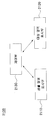
- an information acquisition unit for obtaining information using at least one sensing means, a voltage signal generation unit for generating a voltage signal based on the obtained information, and based on the generated voltage signal
- an apparatus comprising a display unit in which at least one of color and transmittance is variably controlled, the display unit including a solution provided between two or more electrodes at least one of which is transparent and a solution consisting of a plurality of particles dispersed in the solvent.
- the solution represents a variable electric polarization characteristic—the amount of electric polarization induced by a change in the electric field—is applied, and an electric field corresponding to the voltage signal is applied between the electrodes provided with the solution, thereby increasing the intensity and direction of the electric field.
- the display unit may vary the color of the display unit by changing the wavelength of light reflected from the particles by controlling the distance between the particles.
- the wavelength of the light reflected from the display unit is characterized in that it is changed continuously or in an analog manner.
- the wavelength of the light reflected from the display unit is characterized in that it is changed continuously or in an analog manner within a single pixel of the display unit.
- the device is characterized in that it further comprises a light emitting display element.
- the device further comprises a solar cell.
- the display portion is characterized in that at least part of the surface of the device.
- Furniture according to an aspect of the present invention includes the device, wherein the display unit is disposed to cover at least a part of the exterior area, and displays a color selected by the user on the display unit.
- An electronic device includes the device, and information about a state of charge of a battery, wherein the information about the state of charge of the battery includes at least one of a charge amount, a current value, and a voltage value of the battery. It is characterized by displaying a color corresponding to-on the display portion.
- a camouflage device includes the device, wherein the information about the image of the surrounding environment—Information about the image of the surrounding environment is based on at least one of color, pattern, and brightness of the image of the surrounding environment. Including information on the display unit, the color corresponding to the display unit being displayed on the display unit.
- An acoustic device includes the device, and information on the output sound, wherein the information on the sound is information on at least one of the intensity, frequency, rhythm, pitch, beat and genre of the sound. Includes-characterized in that to display a color corresponding to the display unit.
- the diagnostic apparatus includes the apparatus, and information about a state of the human body, wherein the information about the state of the human body includes information about at least one of heart rate, blood pressure, body temperature, and brain waves. It is characterized by displaying a color corresponding to-on the display portion.
- the clock device includes the device, and displays a color corresponding to at least one of time and time on the display unit.
- the heat transfer device includes the device, and displays a color corresponding to information on the ambient temperature or the temperature of the heat transfer device on the display unit.
- a humidifier device includes the device and is characterized by displaying a color corresponding to the information on the ambient humidity on the display unit.
- a transport apparatus includes the apparatus and corresponds to information about an exercise state, wherein the information about the exercise state includes information about at least one of speed, acceleration, angular velocity, and angular acceleration. Color is displayed on the display unit.
- the effect of being able to implement a full color structural color continuously or in an analog manner is achieved by controlling the wavelength of the light reflected from the particles.
- colors can be implemented continuously or in an analog manner within a single pixel
- various colors can be simply implemented as compared with a conventional method of mixing R, G, and B.
- various colors are implemented by mixing colors of three pixels corresponding to R, G, and B.
- various colors may be implemented using only a single pixel.
- the selected sample color can be displayed on the target area in response to any one of the at least one sample color displayed on the sample area being selected, thereby allowing the user to color the light reflected from the photonic crystal.
- the effect of being able to provide a user interface that enables intuitive control of the is achieved.
- the color corresponding to the sensing information obtained from various sensing means can be displayed on the target area, it is possible to visually express various sensing information by using the color of the light reflected from the photonic crystal. Is achieved.
- an exterior or surface or frame capable of realizing a full range of colors analogously, that is, continuously, rather than digitally implementing colors by mixing R, G, and B is possible.
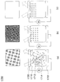
- FIGS. 1 and 2 are diagrams exemplarily illustrating a configuration of particles included in a display device according to an exemplary embodiment.
- FIG. 3 is a diagram illustrating a configuration in which particles or a solvent are polarized as an electric field is applied according to an embodiment of the present invention.
- FIG. 4 is a diagram illustrating unit polarization characteristics by an asymmetrical arrangement of molecules according to an embodiment of the present invention.
- 5 is a diagram showing hysteresis curves of the dielectric, ferroelectric, and superphase dielectrics.
- FIG. 6 is a view exemplarily showing a material having a perovskite structure that may be included in a particle or a solvent according to an embodiment of the present invention.
- FIG. 7 is a view conceptually showing a configuration for controlling the spacing of particles according to an embodiment of the present invention.
- FIG. 8 is a view conceptually showing a configuration for controlling the spacing of particles according to an embodiment of the present invention.
- FIG. 9 is a diagram illustrating a configuration of a display device according to an exemplary embodiment of the present invention.
- FIGS. 10 and 11 are views conceptually illustrating a configuration of a display device according to the exemplary embodiments of the present invention.
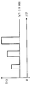
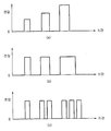
- FIGS. 12 to 14 are diagrams exemplarily illustrating a pattern of voltages applied to a display device according to an exemplary embodiment of the present invention.
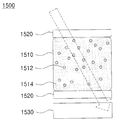
- FIG. 15 is a diagram illustrating a configuration of a display device including a solar cell unit according to an embodiment of the present invention.
- 16 is a diagram exemplarily illustrating a configuration of a display device displaying black or white according to an embodiment of the present invention.
- 17 is a diagram illustrating a configuration of a display device implementing a transparent display according to an embodiment of the present invention.
- FIG. 18 is a diagram illustrating a configuration in which a reflective display device and a light emitting display device are combined according to an embodiment of the present invention.
- 19 and 20 are views exemplarily illustrating a configuration for controlling light transmittance according to another embodiment of the present invention.
- FIG. 21 is a diagram exemplarily illustrating a configuration of a display device that allows a sample color selected by a user to be displayed on a target area, according to an exemplary embodiment.
- 22 and 23 are diagrams exemplarily illustrating a configuration of an application device including a display device according to an exemplary embodiment.
- FIG. 24 is a diagram exemplarily illustrating a configuration of a display device that allows a color corresponding to sensing information obtained from various sensing means to be displayed on a target area, according to an exemplary embodiment.
- 25 to 33 are views exemplarily illustrating a configuration of an application device including a display device according to an exemplary embodiment of the present invention.
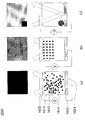
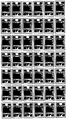
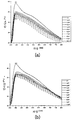
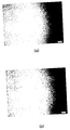
- 34 and 35 illustrate graphs and photographs of light reflected from particles as a result of performing an experiment in which an electric field is applied in a state in which charged particles are dispersed in a solvent having electrical polarization characteristics, according to an embodiment of the present invention. It is a figure which shows.
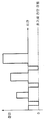
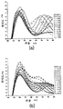
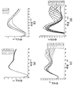
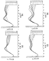
- 36 and 37 are graphs showing wavelengths of light reflected from particles when an electric field is applied in a state in which charged particles are dispersed in various solvents having different polarity indices according to an embodiment of the present invention. It is a figure which shows.
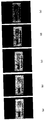
- FIG. 40 is a diagram illustrating experimental results of a configuration of implementing a transparent display according to an embodiment of the present invention.
- FIG. 41 is a diagram illustrating a result of experimenting with display performance according to a viewing angle of a display device according to an exemplary embodiment (that is, results of an experiment regarding a viewing angle of a display).
- 47 is a schematic block diagram of an apparatus according to an embodiment of the present invention.
- a plurality of charged particles are dispersed in a solvent having electrical polarization characteristics, or a plurality of particles having electrical charge and electrical polarization characteristics are dispersed in a solvent. It is a main technical feature that a full color display can be realized by using photonic crystal characteristics by controlling an interval of particles by applying an electric field.
- both the plurality of particles and the solvent may have electrical polarization characteristics, in which case the spacing of the particles can be made more reliable.
- the electrical polarization characteristic may also be characterized in that the electrical polarization is generated when the electric field is applied, but the total electric polarization amount is increased when the electric field is applied may be an advantageous characteristic in the present invention. Such electrical polarization characteristics will be described later in detail.
- FIGS. 1 and 2 are diagrams exemplarily illustrating a configuration of particles included in a display device according to an exemplary embodiment.
- the particles 110 may be dispersed in the solvent 120.
- the particle 110 may have a positive charge or a negative charge. Therefore, when an electric field is applied to the particles 110, the particles 110 may be moved (ie, electrophoretic) due to electric charges generated by the electric charges and the electric fields of the particles 110.
- the plurality of particles 110 may be arranged at a predetermined interval without contacting each other due to mutual electrical repulsion due to charges of the same sign. Can be.
- the diameter of the particle 110 may be several nm to several hundred ⁇ m, but is not necessarily limited thereto.
- the particle 110 may be configured in the form of a core-shell 112 made of different materials as shown in FIG. As shown in (b) of FIG. 2, it may be configured in the form of a multi-core (multi-core) 114 made of heterogeneous materials, and as a cluster 116 of a plurality of nanoparticles as shown in FIG. It may be configured, and the charge layer 118 having a charge may be configured to surround these particles.
- multi-core multi-core
- the charge layer 118 having a charge may be configured to surround these particles.
- the particle 110 is silicon (Si), titanium (Ti), barium (Ba), strontium (Sr), iron (Fe), nickel (Ni), cobalt (Co ), Lead (Pb), aluminum (Al), copper (Cu), silver (Ag), gold (Au), tungsten (W), molybdenum (Mo), zinc (Zn), zirconium (Zr) It can consist of a sonar or a compound containing them.
- the particle 110 according to an embodiment of the present invention may be made of a polymer material such as polystyrene (PS), polyethylene (PE), polypropylene (PP), polyvinyl chloride (PVC), and polyethylen terephthalate (PET).
- PS polystyrene
- PE polyethylene
- PP polypropylene
- PVC polyvinyl chloride
- PET polyethylen terephthalate
- the particle 110 according to an embodiment of the present invention may be configured as a form in which a material having a charge is coated on particles or clusters having no charge.
- the surface is processed by an organic compound having particles (carboxylic acid groups, ester groups, acyl groups), the surface is processed (or coated) by an organic compound having a hydrocarbon group ( Or coated) particles, particles whose surfaces are processed (coated) by a complex compound containing halogen (F, Cl, Br, I, etc.) elements, including amines, thiols, and phosphines.
- Particles whose surface is processed (coated) by the coordination compound, and particles having a charge by forming radicals on the surface may correspond thereto.
- the surface of the particle 110 may be coated with a material such as silica, a polymer, a polymer monomer, or the like, so that the particle 110 may have high dispersibility and stability in the solvent 120.
- the solvent 120 may be made of a material having a specific gravity similar to that of the particle 110 so that the particle 110 may be uniformly dispersed in the solvent 120, and the particle 110 may be formed. May be composed of a material suitable for stably dispersing in the solvent 120. For example, it may include a halogen carbon oil having a low dielectric constant, dimethyl silicone oil and the like.
- the particles 110 and the solvent in order to effectively exhibit photonic crystallinity by maintaining a stable colloidal state without the particles 110 precipitated in the solvent 120 to be described later, the particles 110 and the solvent (
- the value of the electrokinetic potential (ie, zeta potential) of the colloidal solution composed of 120 may be higher than or equal to a predetermined value, and the difference in specific gravity between the particles 110 and the solvent 120 may be equal to or less than the predetermined value.
- the difference in refractive index between the solvent 120 and the particles 110 may be equal to or greater than a predetermined value.
- the absolute value of the interfacial potential of the colloidal solution may be 10mV or more, the difference in specific gravity of the particle 110 and the solvent 120 may be 5 or less, the difference in the refractive index of the particle 110 and the solvent 120 0.3 or more.
- the particle 110 may be configured to reflect light of a specific wavelength, that is, have a unique color. More specifically, the particle 110 according to an embodiment of the present invention may have a specific color through oxidation control or coating of inorganic pigments, pigments, and the like. For example, Zn, Pb, Ti, Cd, Fe, As, Co, Mg, Al, etc., including chromophores, in the form of oxides, emulsions, lactates, etc., are coated on the particles 110 according to the present invention.
- the dye to be coated on the particles 110 may be used as the dye to be coated on the particles 110 according to the present invention.
- the particle 110 may be a material having a specific structural color to display a specific color.
- particles such as silicon oxide (SiO x ) and titanium oxide (TiO x ) may be formed to be uniformly arranged at regular intervals in a medium having a different refractive index to reflect a light having a specific wavelength.
- the solvent 120 may also be configured to reflect light of a specific wavelength, that is, have a unique color. More specifically, the solvent 120 according to the present invention may include a material having a pigment, a dye, or a material having a structural color by photonic crystal.
- the solution including the solvent in which the particles included in the display device are dispersed may have an electrical polarization characteristic (the electrical polarization changes as the electric field is applied).
- the electrical polarization characteristic of the solution may be characterized by at least one of the particles or the solvent constituting the solution exhibiting electrical polarization characteristics or interaction thereof.
- solutions (particles and solvents) that exhibit electrical polarization characteristics are materials that are electrically polarized by any one of electron polarization, ion polarization, interfacial polarization, and rotational polarization as an external electric field is applied due to an asymmetrical charge distribution of atoms or molecules. It may include.
- At least one of the particles or the solvent according to an embodiment of the present invention may cause electric polarization when an electric field is applied, and at least one of the particles or the solvent as the intensity or direction of the electric field applied to the particles or the solvent is changed. May change the amount of electrical polarization.
- the change in electric polarization amount when the electric field is changed may be referred to as a variable electric polarization property. The greater the amount of electrical polarization induced when an electric field is applied, the greater the advantage, since the spacing between particles can be arranged more evenly.
- FIG. 3 is a diagram illustrating a configuration in which particles or a solvent are polarized as an electric field is applied according to an embodiment of the present invention.
- the unit polarization shown in (c) and (d) of FIG. 3 may occur in an asymmetrical arrangement of electrons or ions or in an asymmetric structure of molecules, and due to such unit polarization, an external electric field is applied. If not, a fine residual polarization value may appear.
- Figure 4 is a diagram illustrating unit polarization characteristics by asymmetrical arrangement of molecules according to an embodiment of the present invention. More specifically, Figure 4 shows a case of water molecules (H 2 O) by way of example, in addition to the water molecules, trichloroethylene, carbon tetrachloride, Di-Iso-Propyl Ether, Toluene, Methyl-t-Bytyl Ether, Xylene, Benzene , DiEthyl Ether, Dichloromethane, 1,2-Dichloroethane, Butyl Acetate, Iso-Propanol, n-Butanol, Tetrahydrofuran, n-Propanol, Chloroform, Ethyl Acetate, 2-Butanone, Dioxane, Acetone, Metanol, Ethanol, Acetonitrile, Acetic Acid , Dimethylformamide, Dimethyl Sulfoxide, Propylene carbonate, N, N-Dimethyl
- the amount of polarization increases as the external electric field is applied, and even if the external electric field is not applied, the residual polarization amount is large and the ferroelectric material in which hysteresis remains. It may include a superparaelectric material in which the polarization amount increases as the external electric field is applied and the residual polarization amount does not appear and no hysteresis is left when the external electric field is not applied. Referring to FIG. 5, a hysteresis curve according to an external electric field of the paraelectric material 510, the ferroelectric material 520, and the superphase dielectric material 530 may be checked.
- the particles or the solvent according to an embodiment of the present invention may include a material having a perovskite structure, ABO 3 PbZrO as a material having a perovskite structure such as 3 , PbTiO 3 , Pb (Zr, Ti) O 3 , SrTiO 3 BaTiO 3 , (Ba, Sr) TiO 3 , CaTiO 3 , LiNbO 3 Examples thereof may be mentioned.
- ABO 3 PbZrO as a material having a perovskite structure such as 3 , PbTiO 3 , Pb (Zr, Ti) O 3 , SrTiO 3 BaTiO 3 , (Ba, Sr) TiO 3 , CaTiO 3 , LiNbO 3 Examples thereof may be mentioned.
- FIG. 6 is a view exemplarily showing a material having a perovskite structure that may be included in particles or a solvent according to an embodiment of the present invention.
- the position of PbZrO 3 (or PbTiO 3) PbZrO depending on the direction of the external electric field is applied to the third (or PbTiO 3) Zr (or Ti) (that is, B of the ABO 3 structure) in the This may cause the polarity of the entire PbZrO 3 (or PbTiO 3 ) to be changed.
- the solvent may include a material having a polarity index of 1 or more.
- each molecule and each particle of the solvent has no electric polarization amount, but if the electric field is applied to each molecule and each At least one of the particles is electrically polarized, such that at least one of the total electrical polarization amount of the plurality of particles and the total electrical polarization amount of the solvent may be increased.
- at least one of each molecule and each particle of the solvent is electrically polarized, but at least one of the total amount of electrical polarization of the solvent and the total amount of electrical polarization of the plurality of particles is zero.
- At least one of the total electric polarization amount of the plurality of particles and the total electric polarization amount of the solvent may be increased.
- at least one of each molecule and each particle of the solvent is electrically polarized such that at least one of the total amount of electrical polarization of the solvent and the total amount of electrical polarization of the plurality of particles is zero.
- at least one of the total electric polarization amount of the plurality of particles and the total electric polarization amount of the solvent may be a second value greater than the first value.
- the three-dimensional structure in order to generate steric hindrance repulsion between the particles included in the display device, the three-dimensional structure may be formed on the surface of the particles.
- a functional group or a surfactant may be used as the three-dimensional structure formed on the particle surface.
- the particles contain a material that is electropolarized and the surface or particle has a steric hindrance repulsive force between the particles, but the charge is weak to configure the electrophoretic effect to minimize, the particles or solution
- the amount of electric polarization changes according to the external electric field, effectively causing local short range attraction between particles, and the local short range steric hindrance repulsion between particles is effectively caused by the three-dimensional structure formed through particle surface treatment. Although generated, it is possible to minimize a phenomenon that charged particles are attracted to the electrode by long range electophoretic force caused by an external electric field.
- an organic ligand can be treated on the particle surface.
- composition of the particles and the solvent according to the present invention is not necessarily limited to those listed above, but within the range in which the object of the present invention can be achieved, that is, within the range in which the spacing of the particles can be controlled by an electric field. Note that changes can be made as appropriate.
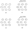
- an electric field when an electric field is applied to the particles and the solvent in a state in which a plurality of particles having a charge of the same sign is dispersed in a solvent having electrical polarization characteristics, the plurality of particles due to the charge of the particles
- An electric attraction force proportional to the intensity of the electric field and the amount of charge of the particles is applied to the particles, whereby the plurality of particles are electrophoresis and move in a predetermined direction, thereby narrowing the spacing of the particles.
- the spacing of the particles becomes narrower, the electrical repulsion generated between the plurality of particles having the same charge with each other increases, so that the spacing of the particles does not continue to be narrowed, thereby achieving a predetermined balance and thus the plurality of particles.
- the particles of can be arranged at regular intervals.
- the solvent polarized unit is arranged in a predetermined direction by the electric field applied from the outside and the electric charges of the surrounding particles, thereby forming a local polarization region centering on the particles.
- the particles of can be arranged more regularly and stably while maintaining a predetermined interval.
- the electrical attraction due to the external electric field, the electrical repulsive force between the particles having the same code charge and the electrical attraction due to the polarization of the plurality of particles at a distance (equilibrium) It can be arranged regularly.
- the spacing of the particles can be controlled at a predetermined interval, and the plurality of particles arranged at a predetermined interval can function as a photonic crystal. Since the wavelength of the light reflected from the plurality of particles arranged regularly is determined by the spacing of the particles, the wavelength of the light reflected from the plurality of particles can be arbitrarily controlled by controlling the spacing of the particles.
- the pattern of the wavelength of the reflected light varies depending on factors such as the intensity and direction of the electric field, the size and mass of the particles, the refractive index of the particles and the solvent, the amount of charge of the particles, the electrical polarization characteristics of the solvent, and the concentration of the dispersed particles in the solvent. May appear.
- the unit polarized solvent 710 around the charged particles 720 interacts with the charges of the particles, so that they are strongly arranged in the direction of the particles, and the distance from the particles is increased.
- the unit polarized solvents 710 may be arranged in an orderly manner (see FIG. 7A).
- the unit polarized solvent 710 located in a region where the influence of the charge of the particles 720 is not affected that is, a region far from the particles 720).
- the unit polarized solvent 710 located in the region in which the electrical attraction due to the charge of the particles 720 is strongly applied that is, the region adjacent to the particles 720
- the anode or the cathode of the unit polarization may be arranged in a direction facing the particles 720, and thus the unit polarization solvent 710 of the peripheral region of the particles 720 may be arranged.
- FIG. 7 is a schematic diagram of a solvent having residual polarization, but may be similarly applied to a solvent having an electric polarization characteristic as an electric field is applied even in the absence of residual polarization.
- the plurality of particles when an electric field is applied to the particles and the solvent in a state in which a plurality of particles having the same charge and having the electrical polarization property are dispersed in the solvent, the plurality of particles due to the charge of the particles An electric force in proportion to the intensity of the electric field and the amount of charge of the particles is applied to the particles of the particles. Accordingly, the plurality of particles are electrophoresis and move in a predetermined direction, thereby narrowing the spacing of the particles.
- the electrical repulsive force generated between the plurality of particles having the same charge with each other increases, so that the spacing of the particles does not continue to be narrowed, thereby achieving a predetermined balance and thus the plurality of particles.
- the particles of can be arranged at regular intervals.
- the particles exhibiting electrical polarization characteristics are polarized by an electric field to be polarized in the direction of the electric field, and electrical attraction is locally generated between the plurality of polarized particles so that the plurality of particles maintain a predetermined interval. It can be arranged more regularly and stably.
- the electrical attraction due to the external electric field, the electrical repulsive force between the particles having a charge of the same sign and the electrical attraction due to the polarization of the plurality of particles at a distance (equilibrium) It can be arranged regularly.
- the spacing of the particles can be controlled at a predetermined interval, and the plurality of particles arranged at a predetermined interval can function as a photonic crystal. Since the wavelength of the light reflected from the plurality of particles arranged regularly is determined by the spacing of the particles, the wavelength of the light reflected from the plurality of particles can be arbitrarily controlled by controlling the spacing of the particles.
- the pattern of the wavelength of the reflected light varies depending on factors such as the intensity and direction of the electric field, the size and mass of the particles, the refractive index of the particles and the solvent, the amount of charge of the particles, the electrical polarization characteristics of the particles, the concentration of dispersed particles in the solvent, and the like. May appear.
- FIG. 8 is a view conceptually showing a configuration for controlling the spacing of particles according to an embodiment of the present invention.
- the particles 810 when (a) the external electric field is not applied, the particles 810 are not polarized, but (b) when the external electric field is applied, the particles of the electrical polarization characteristics included in the particles 810 are applied.
- the particles 810 may be polarized, thereby allowing the particles 810 to be regularly arranged at a predetermined interval.
- the greater the polarization of the solvent or particles the greater the degree of interaction between the polarization zone 730 or the particles 810, so that the particles are arranged more regularly. You can do it.
- the particles or the solvent have the electrical polarization characteristics. That is, even when a particle or a solvent does not have electrical polarization characteristics, if the particle has a charge, the plurality of electric charges due to an external electric field and the electric repulsive force between a plurality of particles having a charge of the same sign are balanced with each other.
- the particles of may be arranged regularly, and the plurality of regularly arranged particles may form a photonic crystal that reflects light of any wavelength.
- the particles according to the present invention do not necessarily have a charge. That is, even if a particle has an electric polarization characteristic and has a three-dimensional structure capable of generating steric hindrance repulsion even when the particle has no electric charge, the electrical attraction between adjacent particles caused by the electric polarization caused by an external electric field and
- the plurality of particles may be regularly arranged at a distance where the repulsive force due to the steric hindrance effect is balanced, and the plurality of regularly arranged particles may form a photonic crystal that reflects light of any wavelength.
- FIG. 9 is a diagram illustrating a configuration of a display device according to an exemplary embodiment of the present invention.
- the display device 900 may include a display unit 910 and an electrode 920. More specifically, according to the exemplary embodiment of the present invention, the display unit 910 may include a plurality of particles 912 having electric charges having the same sign and having electric polarization characteristics, dispersed in the solvent 914, and the present invention. According to another exemplary embodiment of the present disclosure, the display unit 910 may include a plurality of particles 912 having electric charges having the same sign as being dispersed in the solvent 914 having electrical polarization characteristics.
- the configuration of the display device according to the embodiment of the present invention conceptually shown in Figs. 10 and 11, respectively. Since these embodiments of the present invention have already been described in detail with reference to FIGS.
- the display unit 910 and the electrode 902 are separately displayed, but when such a display device is embedded in or included in a specific object, the display unit and the electrode may be collectively referred to as a display unit. That is, the display portion also needs to consider a configuration including both the solution and the electrode.
- the display unit 910 reflects light of an arbitrary wavelength (that is, full color light when viewed in the visible light region) according to the intensity and direction of the applied electric field. This may be achieved by controlling the spacing of the particles 912 according to the strength and direction of the electric field applied to the display unit 910 according to the principle described above. That is, as described above, according to an embodiment of the present invention, since the particle spacing can be adjusted within a single pixel (the smallest display unit that can be independently controlled), a full color color can be realized.
- the color implementation is very simple because it is not necessary to mix colors by using three pixels corresponding to R, G, and B, or using three color filters corresponding to R, G, and B as in the above.
- the configuration of the display device can be made very simple.
- pigments corresponding to R, G, and B are used to implement color by mixing them, colors that can be implemented are limited, and above all, the color implementation is complicated, so that the driving circuit or display device may be complicated.
- the configuration is complicated.
- the color can be implemented in a simple manner, the configuration of the driving circuit and the display device is not complicated, so it may be of great value in economic aspects.
- the electrode 920 performs a function of applying an electric field of a predetermined intensity and direction to the display unit 910, and the intensity of the electric field applied through the electrode 920.
- the direction may be appropriately controlled in accordance with the wavelength of light desired to be reflected from the display portion 910.
- FIGS. 12 to 14 are diagrams exemplarily illustrating a pattern of voltages applied to a display device according to an exemplary embodiment of the present invention.
- the display device sequentially applies electric fields having different intensities and different directions with respect to particles and solvents to implement a continuous display.
- the controller may further include a controller (not shown) that performs a function of initializing the spacing of particles during the change. More specifically, the control unit according to an embodiment of the present invention, in sequentially applying the first voltage and the second voltage to the electrode for applying the electric field to the particles and the solvent, after applying the first voltage after applying the second voltage By applying a reset voltage in a direction opposite to the first voltage to the particles and the solvent before the application, the function of returning the interval of the particles arranged at a predetermined interval by the first voltage to the initial state.
- the display device can improve display performance, for example, to improve an operation speed and suppress an afterimage.
- the initialization voltage is applied in the opposite direction to the voltage applied immediately before, the particles arranged by moving in a predetermined direction by the voltage applied immediately before are forcibly moved in the opposite direction. In this case, even when the display device is turned off, the operation speed can be increased.
- the display device sequentially applies an electric field of different intensities and different directions to particles and a solvent in order to implement a continuous display in advance, thereby realizing a gap between particles in advance.
- It may further include a controller (not shown) that performs a function of maintaining at predetermined intervals.
- the control unit by sequentially applying the first voltage and the second voltage to the electrode for applying the electric field to the particles and the solvent, by applying a predetermined standby voltage in advance In a set state, the first electric field and the second voltage are applied so that the spacing of the particles can be quickly controlled at a desired spacing.
- the display device may improve display performance by increasing response speed and speeding up screen switching. That is, in the conventional electronic paper technology, in order to display a specific color, particles of a specific color had to be moved from one end to the other end in a cell, but in the present invention, the reflected light in the visible light band does not appear. Particles are localized by applying a relatively low level of atmospheric voltage to densify particles in one direction in the cell, and then applying a voltage above a certain level to implement a photonic crystal that reflects light in the visible band. By moving, it is possible to implement a photonic crystal that reflects light in the visible light band to speed up the operation.
- the display device implements a continuous display by sequentially applying different intensities and different directions of electric fields to particles and solvents.
- the controller may further include a controller (not shown) that performs a function of applying electric fields of various patterns in an application time.
- the control unit in applying the voltage to the electrode for applying the electric field to the particles and the solvent, can increase or decrease the level of the voltage to a predetermined voltage (Fig. 14 (a) Can be arbitrarily increased or decreased (see (b) of FIG. 14), and the same effect as in the case where the voltage is applied continuously can be achieved by repeatedly applying the discontinuous pulse voltage. (See FIG. 14C).
- the display device may improve display performance by enabling various types of display and reducing power consumption.
- the electric field application pattern according to the present invention is not necessarily limited to those listed above, but suitably within the range in which the object of the present invention can be achieved, that is, within the range in which the spacing of particles can be controlled by the electric field. Note that it may change.
- FIG. 15 is a diagram illustrating a configuration of a display device including a solar cell unit according to an embodiment of the present invention.
- the display device 1500 further includes a solar cell unit 1530 that performs a function of generating and storing electromotive force using light passing through the display device 1500. It may include.
- the electromotive force generated by the solar cell unit 1530 may be used to generate a voltage applied to the electrode 1520, whereby the display device 1500 may be applied to an external power supply. It is possible to implement the photonic crystal display described above without depending on.
- the combination of the display device and the solar cell unit according to the present invention is not necessarily limited to those listed above, and the electromotive force generated by the solar cell unit may be used for other purposes than driving the display device. will be.
- the display device using photonic crystallinity operates on the principle of selectively reflecting light of a specific wavelength among incident light, it may not be easy to express complete black or white color using the display device using photonic crystallinity. have.
- a configuration of displaying black or white by using a display device using photolithography will be described.
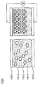
- 16 is a diagram exemplarily illustrating a configuration of a display device displaying black or white according to an embodiment of the present invention.
- the display unit 1610 may include black particles 1612, and the electrodes may include a transparent upper electrode 1620 and white first and second lower electrodes 1622 and 1624. .
- the particles 1612 do not form a photonic crystal and reflect black of their own color, The scattered light due to the difference in refractive index can be reflected, and thus the display unit 1610 can display black (see FIG. 16A).
- the black particles 1612 may be arranged in close contact with the upper electrode 1620, and in this case, the display unit 1610 may be black. Can be displayed.
- the display unit 1610 when an electric field having an appropriate intensity is applied to the display unit 1610, light having a desired wavelength range may be reflected from the particles 1612 constituting the photonic crystal (see FIG. 16B).
- an electric field having a predetermined intensity or more when an electric field having a predetermined intensity or more is applied to the display unit 1610, as the size of the electric attraction causing electrophoresis becomes too large, the spacing of the particles 1612 may not be maintained at an appropriate interval, and the particles 1612 may not be formed.
- an electric field of a predetermined value or more is applied only to a portion of the first lower electrode 1622, all the particles 1612 included in the display unit 1610 do not form a photonic crystal and are applied to the first lower electrode 1622. It can be swept into a narrow area covered by it. Accordingly, the second lower electrode 1624 may reflect white, which is its own color, without being affected by the particles 1612 that are black, so that the display unit 1610 may display white ( See FIG. 16 (c)).
- the colors of the particles and the electrodes are specified as black and white in the embodiment of FIG. 16, the colors of the particles and the electrodes that can be applied to the display device of the present invention may be changed. It may be set to transparent.
- a configuration of transparent display using the display device using the photolithography will be described.
- 17 is a diagram illustrating a configuration of a display device implementing a transparent display according to an embodiment of the present invention.
- the display unit 1710 may include transparent particles 1712 including a visible light transmissive material such as SiO x, and the electrode may also include a transparent upper electrode 1720 and a lower electrode 1722.
- the intensity of the electric field applied to the display unit 1710 is less than the predetermined value or when the electric field is not applied, the particles 1712 do not form a photonic crystal and do not exhibit color due to the photonic crystal. The incident light can be scattered by this (see FIG. 17A).
- an electric field having an appropriate intensity is applied to the display unit 1710, light having a desired wavelength range may be reflected from the particles 1712 constituting the photonic crystal (see FIG. 17B).
- the interval between the particles 1712 is shorter than the visible light band (for example, Only light in the ultraviolet band) may be reflected. That is, in this case, since the light in the visible ray band is transmitted without being reflected by the photonic crystal, the upper electrode 1720, the lower electrode 1722, and the particles 1712 are all transparent, and thus the display device of FIG. It may be transparent as a whole (see FIG. 17C).
- the display device when a voltage below a certain level is applied, incident light is scattered to become translucent or opaque, and when a voltage of a specific range is applied, the display device is visible by a regular arrangement of particles (that is, photonic crystal).
- the incident light of the light band is reflected to display a predetermined color, and when a voltage exceeding a certain level is applied, the interval of the particles becomes too narrow, so that the incident light of the visible light band is transmitted and is shorter than the visible light band. Incident light in the ultraviolet band is reflected and becomes transparent.
- the display device it is possible to manufacture a variable color glass, which can reflect light in any wavelength range, and also become transparent or opaque, and furthermore, by adjusting the transparency of the display device It is also possible to implement a display system in which a specific color or pattern present on one side is visible or invisible to an observer on the other side.
- FIG. 18 is a diagram illustrating a configuration in which a reflective display device and a light emitting display device are combined according to an embodiment of the present invention.
- the reflective display devices 1810 and 1820 and the separate light emitting display devices 1830 and 1840 according to the exemplary embodiment may be combined. More specifically, the light emitting display devices 1830 and 1840 are coupled to the lower portions of the reflective display devices 1810 and 1820 according to the exemplary embodiment, and the reflective display devices 1810 and 1820 and the light emitting display devices are combined.
- the reflected light by the photonic crystal is displayed in the mode in which the reflective display devices 1810 and 1820 operate, and conversely, in the mode in which the light emitting display devices 1830 and 1840 operate, Light generated in the back light of the light transmitted through the color filter may be displayed through the light crystal particles.
- the power consumption can be reduced in comparison with the case where only the light emitting display device is used, and the range of colors that can be displayed in comparison with the case where only the reflective display device is used.
- the effect of widening can be achieved.
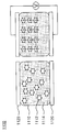
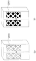
- 19 and 20 are diagrams exemplarily illustrating a configuration of controlling light transmittance according to another embodiment of the present invention.
- the upper electrodes 1930 and 2030 and the lower electrodes 1940, 1950 and 2040 of the display devices 1900 and 2000 may be made of a light transmissive material.
- particles in the solvent may be irregularly dispersed, and in this case, the transmittance of the light incident on the particles and the solvent is not particularly controlled. That is, some of the light incident on the particles and the solvent may be scattered or reflected by a plurality of irregularly dispersed particles, and the other may pass through the particles or the solvent as they are.
- the plurality of particles when an electric field is applied to the particles and the solvent in a state in which the plurality of particles having the electrical polarization characteristics are dispersed in the solvent, the plurality of particles are polarized by the electric field to cause Depending on the direction, all of them can be polarized in the same direction. Since the electrical attractive force is generated between the plurality of particles polarized in the same direction, the plurality of particles dispersed in the solvent attract each other in a direction parallel to the direction of the electric field. It can be arranged regularly. Therefore, by controlling the intensity or direction of the electric field to control the arrangement of the plurality of particles regularly arranged in a direction parallel to the direction of the electric field it is possible to control the transmittance of the incident light to the solvent and particles.
- the incident light 2040 when the electric field is not applied, the incident light 2040 is scattered or reflected by the particles 2010 and the solvent 2020 or the solvent 2020 because the plurality of particles 2010 are irregularly arranged in the solvent. ) As it is, the light transmittance of the incident light 2040 is not controlled but becomes a low state (see FIG. 20A). 20, when the electric field is applied while the plurality of particles 2010 having electrical polarization characteristics are dispersed in the solvent 2020, the plurality of particles 2010 are parallel to the direction of the incident light 2040.
- the transmittance of the incident light 2040 may be relatively high (see FIG. 20B).
- the transmittance of the incident light 2040 may be relatively low (see FIG. 20C).
- the corresponding color is displayed on the target area in response to being selected by the user from at least one sample color displayed on the sample area, or obtained from various sensing means.
- a user interface that allows the user to intuitively control the color displayed on the target area can be visually represented.
- the corresponding light transmittance is implemented on the target region in response to the selection of at least one level of the sample light transmittance implemented on the sample region by the user, or various sensing
- the light transmittance corresponding to the sensing information obtained from the means to be implemented on the target area it is possible to provide a user interface that allows the user to intuitively control the light transmittance implemented on the target area and to visually express various sense information. Can be.
- FIG. 21 is a diagram exemplarily illustrating a configuration of a display device that allows a sample color selected by a user to be displayed on a target area, according to an exemplary embodiment.
- the display device 2100 may include a sample region display 2110, a target region display 2120, and a controller 2130.
- the sample area display 2110 displays at least one sample color on a predetermined sample area or implements at least one level of sample light transmittance so that the user can select the sample area.
- a user interface may be provided to select a desired color among at least one sample color displayed on the image, or to select a desired light transmittance among at least one level of sample light transmittance implemented on the sample region.
- the sample region display unit 2110 may perform a function of generating an input signal relating to the color or light transmittance selected by the user and transmitting it to the controller 2130 to be described later.
- the sample region display unit 2110 by applying an electric field to a plurality of particles and a solvent and adjusting at least one of the intensity and the direction of the electric field to space the particles By controlling to display the color of the light reflected from the particles variably, at least one sample color can be displayed on the sample area.
- the sample region display unit 2110 according to an embodiment of the present invention by applying an electric field to the plurality of particles and the solvent and controlling at least one of the intensity and direction of the electric field to control the position or arrangement of the particles, The transmittance of light incident on the solvent can be controlled.
- At least one sample color displayed adjacent to each other on the sample area may have a wavelength range that is continuous with each other, thereby allowing a user to more accurately select a desired color.
- the touch pad may be implemented on the sample area in which the sample color is displayed, thereby allowing the user to select the sample color more intuitively and naturally.
- the sample color display method or the sample color selection method according to the present invention is not necessarily limited to the above-listed embodiments, but it can be understood that the present invention may be changed within a range capable of achieving the object of the present invention.
- the target area display unit 2120 corresponds to a color selected by the user on the predetermined target area with reference to a control signal transmitted from the controller 2130 to be described later.
- a function of displaying a color or implementing light transmittance corresponding to the light transmittance selected by the user may be performed.
- the target region display unit 2120 by applying an electric field to a plurality of particles and a solvent and adjusting at least one of the intensity and direction of the electric field of the particles
- a predetermined color can be displayed on the target area.
- a color having a continuous wavelength range i.e., which can be changed analogously
- the display means applicable to the target region display unit according to the present invention is not necessarily limited to those listed above, but may be changed within a range capable of achieving the object of the present invention.
- the target area display unit according to another embodiment of the present invention may be mixed with a dye that changes color according to temperature, a dye that changes color according to pressure, and the like.
- the target area display unit 2120 according to an embodiment of the present invention applies the electric field to the plurality of particles and the solvent, and controls the position or arrangement of the particles by controlling at least one of the intensity and the direction of the electric field, thereby controlling the particles and The transmittance of light incident on the solvent can be controlled.
- the controller 2130 may be configured to select either an input signal or at least one level of sample light transmittance relating to selection of at least one sample color displayed on the sample area.
- a control signal or a selected light for acquiring an input signal relating to being selected from the sample area display unit 2110 and displaying a color to be displayed in the target area, that is, a color corresponding to the selected color, with reference to the obtained input signal.
- the control signal for generating light transmittance corresponding to the transmittance may be generated, and the generated control signal may be transmitted to the target region display 2120.
- the controller 2130 may be included in the display device 2100 in the form of an operating system, an application module, and other program modules, and may be physically stored on various known storage devices. Can be.
- the program module may be stored in a remote storage device that can communicate with the display device 2100.
- program modules include, but are not limited to, routines, subroutines, programs, objects, components, data structures, etc. that perform particular tasks or execute particular abstract data types, described below, in accordance with the present invention.
- 22 and 23 are diagrams exemplarily illustrating a configuration of an application device including a display device according to an exemplary embodiment.
- a color of an exterior of a notebook may be controlled by using a display device according to an exemplary embodiment.
- at least one sample color having a continuous wavelength range may be displayed on the sample area 2210 located at one side of the exterior of the notebook, and the user may display the sample area 2210 on the sample area 2210. If green is selected from the displayed sample colors, green may be displayed on the target area 2220, that is, the entire exterior area of the notebook.
- the transparency of the exterior of the notebook may be variably controlled by implementing the light transmittance corresponding to the light transmittance selected by the user on the target area of the notebook.
- a color of an exterior of a furniture may be controlled using a display device according to an exemplary embodiment.
- the target area 2310 implemented in the form of a film may cover at least a part of the exterior of the furniture, and among at least one sample color displayed in the sample area (not shown).
- the aesthetics of the furniture can be improved by variably displaying the color of the main decoration (for example, mother-of-pearl decoration) of the furniture.
- the present invention by implementing a light transmittance corresponding to the light transmittance selected by the user on the target area of the furniture it can also variably control the transparency of the main decoration of the furniture.
- the surface color of the frame may be changed so as to be harmonized with a user's desire or surrounding environment.
- the application areas to which the display device according to an exemplary embodiment of the present invention can be applied are not necessarily limited to those listed above, and include building materials such as walls, ceilings, floors, exterior walls, glass, bags, clothes, pots, etc. It can be applied to any of various fields.
- FIG. 24 is a diagram exemplarily illustrating a configuration of a display device that allows a color corresponding to sensing information obtained from various sensing means to be displayed on a target area, according to an exemplary embodiment.
- the display device 2400 may include a detector 2410, a target area display 2420, and a controller 2430.
- the sensing unit 2410 may perform a function of acquiring various sensing information by using at least one sensing means.
- the sensing unit 2410 may perform a function of generating an input signal related to the sensing information obtained by the sensing unit and transmitting it to the controller 2430 to be described later.
- the sensing means that may be included in the sensing unit 2410 according to an embodiment of the present invention, a gyro sensor, a temperature sensor, a humidity sensor, a pressure sensor, an acoustic sensor, an optical sensor, a current sensor, a voltage sensor, a charge
- a sensor an acidity sensor, an optical sensor, an image sensor, an acoustic sensor, a human body signal sensor, a timer, and the like, and various sensing information about various states of an object to be detected may be obtained.
- the sensing means that can be included in the sensing unit 2410 according to the present invention is not necessarily limited to the above-described sensing means, it will be appreciated that it can be changed within the scope that can achieve the object of the present invention. That is, the sensing information may be information about the surrounding environment of the corresponding device or information input or processed by the user of the corresponding device.
- the target area display 2420 is obtained from the sensing unit 2410 on the predetermined target area with reference to a control signal transmitted from the controller 2430 to be described later. It may perform a function of displaying a color corresponding to the sensing information or implementing light transmittance. More specifically, the target region display unit 2420 according to an embodiment of the present invention, as described above, by applying an electric field to a plurality of particles and a solvent and adjusting at least one of the intensity and direction of the electric field of the particles By controlling the distance so that the color of the light reflected from the particles is displayed variably, a predetermined color can be displayed on the target area.
- a color having a continuous wavelength range (i.e., which can be changed analogously) can be displayed on the target area rather than a color in which several colors are mixed.
- the display means applicable to the target region display unit according to the present invention is not necessarily limited to those listed above, but may be changed within a range capable of achieving the object of the present invention.
- the target area display unit according to another embodiment of the present invention may be mixed with a dye that changes color according to temperature, a dye that changes color according to pressure, and the like.
- the target area display unit 2420 applies the electric field to the plurality of particles and the solvent, and controls the position or arrangement of the particles by controlling at least one of the intensity and the direction of the electric field, thereby controlling the particles and The transmittance of light incident on the solvent can be controlled.
- the control unit 2430 obtains an input signal relating to the sensing information obtained as a result of sensing the state of the object to be detected from the sensing unit 2410, and thus obtained input
- the control signal for the color to be displayed on the target area or the light transmittance implemented in the target area may be generated with reference to the signal, and the generated control signal may be transmitted to the target area display unit 2420.
- the controller 2430 may be included in the display device 2400 in the form of an operating system, an application module, and other program modules, and may be physically stored on various known storage devices. Can be.
- the program module may be stored in a remote storage device that can communicate with the display device 2400.
- such program modules include, but are not limited to, routines, subroutines, programs, objects, components, data structures, etc. that perform particular tasks or execute particular abstract data types, described below, in accordance with the present invention.
- the display device may detect the acidity of the food stored in the refrigerator by using an acidity sensor to obtain sensing information regarding the freshness of the food, that is, the degree of corruption.
- a predetermined color representing the freshness of the food may be displayed on a predetermined area of the exterior of the refrigerator with reference to the acquired sensing information. More specifically, when the freshness of the food is high, the green and the freshness of the food are medium. In the case of yellow, the freshness of the food may be displayed in red.
- a configuration in which the color of the surface changes in accordance with the temperature of the refrigerator by measuring the temperature of the refrigerator can be considered.
- the display device according to the present invention can be manufactured in the form of a thin flexible film and can realize a full color display
- an electronic device mobile phone, notebook, PC
- TVs personal multimedia players (PMPs), refrigerators, etc.
- sound devices such as speakers
- human diagnostic devices clocks
- heating devices air conditioning units
- humidity control devices cars, bicycles, furniture, clothing, building materials (interior walls) , Building exterior walls, glass, advertising panels, etc.
- 25 to 33 are views exemplarily illustrating a configuration of an application device including a display device according to an exemplary embodiment.
- a color of an exterior of an electronic device may be controlled with reference to information about a state of charge (ie, remaining amount) of a battery. More specifically, according to an embodiment of the present invention, the target area 2510 capable of variably displaying the color is disposed on at least a part of the exterior of the portable electronic device, and the charge amount and current value of the battery of the portable electronic device. And displaying a color corresponding to information on the state of charge of the battery of the portable electronic device obtained as a result of sensing the voltage value, on the target area 2510, thereby indicating the state of charge of the battery of the portable electronic device. It can be expressed visually as color.
- the exterior 2510 of the mobile phone does not display any color (see FIG. 25A), and when the battery is low, the exterior 2510 of the mobile phone is left. The user may be visually warned by displaying a gray color in FIG. 25 (b).
- the transparency of the exterior of the battery of the electronic device It can be expressed visually as
- an external color of a terminal device such as a notebook computer or a PC may be controlled with reference to information about contents provided to a user.
- a target area 2610 capable of variably displaying colors may be disposed in at least a part of an exterior of a monitor of a terminal device (for example, a bezel area of a monitor). And displaying the color corresponding to the information about whether the content obtained as a result of recognizing the context information regarding whether the website displayed on the monitor is a harmful website on the target area 2610, thereby providing the information on the terminal device.
- the harmfulness of the content can be visually expressed as the color of the exterior of the monitor of the terminal device.
- the color of the exterior of the terminal device may be variably displayed according to the type of content, the content, the caller of the received call, and the like.
- color of an exterior of a camouflage device such as a helmet, a jacket, a tent, and the like may be controlled with reference to the information on the surrounding environment.
- the target area 2710 that can variably display the color on at least a portion of the exterior of the camouflage helmet, the color of the image of the surrounding environment of the camouflage helmet Camouflage the color, pattern, brightness, etc. of the camouflage helmet to be similar to that of the surrounding environment by displaying a color corresponding to the information on the surrounding environment obtained as a result of recognizing the pattern, brightness, etc. on the target area 2710.
- the color of the exterior of the dragon helmet can be adjusted.
- the camouflage helmet's sheath 2710 may display a color and pattern similar to the concrete wall (see FIG. 27A). If there are many leaves in the vicinity of the camouflage helmet 2710 can be displayed on the color and pattern similar to the leaves (see Fig. 27 (b)).
- the color of an exterior such as a camouflage jacket and a camouflage tent can be adjusted.
- the light transmittance of the outer cover of the camouflage helmet by implementing the light transmittance corresponding to the information on the surrounding environment in the target area, the light transmittance of the outer cover of the camouflage helmet so that the transparency of the camouflage helmet is similar to that of the surrounding environment Can be adjusted.
- the color of the exterior of the acoustic device may be controlled by referring to the information about the output sound. More specifically, according to an embodiment of the present invention, the target area 2810 capable of variably displaying the color is disposed on at least some areas of the exterior of the sound device, and the intensity, frequency, rhythm, and pitch of the sound output. By displaying the color corresponding to the information on the sound obtained as a result of recognizing the beat, genre, etc. in the target area 2810, the information on the sound output from the sound device can be visually expressed as the color of the exterior of the sound device. do. For example, different colors and patterns may be displayed on the exterior 2810 of the acoustic apparatus when the genre of the sound output from the acoustic apparatus is classic and dance (FIGS. 28A and 28B). Reference).
- the light transmittance corresponding to the information about the sound in the target area by implementing the light transmittance corresponding to the information about the sound in the target area, it is possible to visually express the information about the sound output from the sound device as the transparency of the exterior of the sound device. .
- a color of an exterior of an exercise device or a human diagnostic device may be controlled with reference to information about a state of a human body. More specifically, according to an embodiment of the present invention, the target area 2910 that can display the color variably on at least a portion of the exterior of the exercise device or the human diagnostic device is disposed, and the exercise device or the human diagnostic device By displaying the color corresponding to the information on the state of the human body obtained as a result of detecting the user's heart rate, blood pressure, body temperature, brain waves, etc. on the target area 2910, information on the state of the human body is displayed on the exercise device or the human body. It can be visually expressed as the color of the exterior of the diagnostic device.
- the user's heart rate may not be displayed on the exterior 2910 of the treadmill (see FIG. 29 (a)). If applicable, a red color may be displayed on the exterior 2910 of the treadmill (see FIG. 29B).
- the information about the state of the human body can be visually represented as the transparency of the exterior of the exercise device or the human diagnostic device It becomes possible.
- a color of an exterior of a clock or a timer may be controlled by referring to information about a time or a time. More specifically, according to an embodiment of the present invention, the target area 3010 capable of variably displaying the color is disposed on at least a part of the exterior of the clock or the timer, and the color corresponding to the time information is targeted. By displaying in the area 3010, the information about time can be visually represented as the color of the exterior of a clock or a timer. For example, different colors of the exterior 3010 of the clock may be displayed in the morning time zone, the afternoon time zone, and the evening time zone, respectively (see FIGS. 30A, 30B, and 30C).
- the light transmittance corresponding to the information about the time in the target area by implementing the light transmittance corresponding to the information about the time in the target area, it is possible to visually express the information about the time as the transparency of the exterior of the clock or timer.
- the target region 3110 capable of variably displaying the color is disposed on at least a portion of the exterior of the heating device or the heating and cooling device, and corresponding to the information about the detected temperature.
- the information on the temperature can be visually expressed as the color of the exterior of the heat transfer device or the heating and cooling device. For example, when the temperature of the iron plate is only 20 degrees Celsius, the color of the iron plate is very high at 100 degrees Celsius without displaying a different color on the handle portion 3110 of the iron (see FIG. 31 (a)). If hot, a red color may be displayed on the handle portion 3110 of the iron to visually warn the user (see FIG. 31B).
- the present invention by displaying the light transmittance corresponding to the information on the detected temperature on the target area, it is possible to visually express the information on the temperature as the transparency of the exterior of the heating device or heating and cooling device. .
- the color of the exterior of the humidity control device may be controlled with reference to the information on humidity.
- the target area 3210 which can variably display colors, is disposed in at least some areas of the exterior of the humidity control device, and the color corresponding to the detected humidity information is displayed in the target area (
- the information on the humidity can be visually represented as the color of the exterior of the humidity control device.
- the relative humidity measured by the humidifier is only 20%, and the relative humidity is 80% without displaying a different color on the exterior 3210 of the humidifier (see FIG. 32 (a)).
- a blue color may be displayed on the exterior 3210 of the humidifier (see FIG. 32B).
- the color of the exterior of the pot may be variably displayed according to the humidity of the moisture contained in the pot.
- the present invention by displaying the light transmittance corresponding to the information on the detected humidity in the target area, it is possible to visually express the information on the humidity as the transparency of the exterior of the humidity control device.
- a color of an exterior of a moving device such as a car, a motorcycle, a bicycle, a board, a top, or the like may be controlled with reference to information about an exercise state.
- a target area 3310 capable of variably displaying colors is disposed on at least some areas of an exterior of a moving device such as a car, and the speed, acceleration, angular velocity, By displaying the color corresponding to the information on the exercise state obtained as a result of detecting the angular acceleration on the target area 3310, the information about the exercise state can be visually expressed as the color of the exterior of a moving device such as a car.
- the car dashboard 3310 does not display any color (see FIG. 33 (a)), and when the speed of the car is 100 km / h, the car is fast. A red color may be displayed on the dashboard 3310 of to visually warn the user (see FIG. 33B).
- the light transmittance corresponding to the information on the exercise state on the target area by displaying the light transmittance corresponding to the information on the exercise state on the target area, it is possible to visually express the information about the exercise state as the transparency of the exterior of the moving device such as a car. .
- the information acquisition step of obtaining information sensed by the at least one sensing means e.g., obtaining the temperature of the heat transfer device
- a voltage signal generation step step of generating a corresponding voltage signal based on the temperature
- a display step of variably adjusting at least one of color and transmittance of the display area of the target based on the generated voltage signal Adjusting the color of the frame of the device), wherein the wavelength corresponding to the color displayed in the display area can be changed continuously or analogously within a single pixel, thereby digitally converting existing R, G, B digitally.
- FIGS. 34 and 35 are graphs showing light reflected from particles as a result of performing an experiment in which an electric field is applied in a state in which particles having an electric charge are dispersed in a solvent having electrical polarization characteristics, according to an embodiment of the present invention. It is a figure shown as a photograph.
- particles having a charge of 100 nm to 200 nm that are negatively charged and coated with a silicon oxide film were used as particles having a charge, and a solvent having a polarity index greater than 1 was used as the electrical polarization characteristic.
- the intensity of the voltage applied to apply the electric field to the particles and the solvent was set variously in the range of 0V to 5V.
- the graph shown in Figure 34 shows the reflectance of the light reflected from the particles when the electric field of various intensities are applied in the wavelength range of the visible light band, the wavelength pattern of the reflected light according to the change in the intensity of the electric field in Figure 34 The larger the degree of change, the greater the change in the spacing of the particles, which means that by controlling the intensity of the electric field it is possible to reflect light of more wavelengths from the particles.
- the wavelength pattern of the light reflected from the particles varies according to the intensity of the applied electric field (ie, the intensity of voltage). More specifically, the intensity of the applied electric field (ie, It can be seen that as the intensity of the voltage) increases, the wavelength of the light reflected from the particles becomes shorter overall. According to the experimental result of FIG. 34, it can be seen that as the intensity of the applied electric field increases (that is, the intensity of voltage), the color of light reflected from the particles changes from a red color to a blue color. The visual change of the reflected light can be visually confirmed.
- FIGS. 36 and 37 illustrate wavelengths of light reflected from particles when an electric field is applied in a state in which charged particles are dispersed in various solvents having different polarity indices according to an embodiment of the present invention. It is a figure which shows as a graph.
- particles having a size of 100 nm to 200 nm that are negatively charged and coated with a silicon oxide film were used as particles having a charge, and polarity indices were 0, 2, 4, and 5, respectively.
- Phosphorus solvent was used as a solvent having electrical polarization properties. More specifically, the graphs (a), (b), (c), and (d) of FIG.
- the graph shown in Figures 36 and 37 shows the reflectance of the light reflected from the particles when the electric field of various intensities are applied in the wavelength range of the visible light band, the wavelength pattern of the reflected light according to the change in the intensity of the electric field
- a light having an arbitrary wavelength may be adjusted by appropriately adjusting the amount of charge or polarization of a particle, the amount of polarization of a solvent, or the intensity of an applied electric field. It can be seen that it is possible to implement a reflective photonic crystal, thereby implementing a display of an arbitrary full spectrum.
- FIGS. 38 and 39 are graphs showing light reflected from particles as a result of performing an experiment in which an electric field is applied in a state in which particles having charge and electric polarization characteristics are dispersed in a solvent according to one embodiment of the present invention; It is a figure shown as a photograph.
- the SrTiO 3 particles (see FIG. 38 (a)) and the BaTiO 3 particles (see FIG. 38 (a)) charged to have charges, respectively have electric charge and electric polarization. Used as particles with properties, the particles were dispersed in a solvent with a polarity index of zero.
- the reflectivity of the light generally decreases.
- the particles dispersed in the solvent may be electrically polarized and arranged in the direction of the electric field (see (b) of FIG. 39), and due to this arrangement, the number of particles that may reflect incident light may be small. It can be interpreted that the reflectivity of light is reduced.
- the wavelength of reflected light was not drastically changed by using an electric field applied in a state in which particles having electric polarization characteristics were dispersed in a nonpolar solvent, the particles were arranged in a constant direction as the electric field was applied. From this, it can be seen that the wavelength of the reflected light can be changed by optimizing the conditions such as the charge on the particle surface.
- FIG. 40 is a diagram illustrating experimental results of a configuration of implementing a transparent display according to an embodiment of the present invention.
- particles, a solvent, and an electrode made of transparent materials that transmit light in the visible light band were used, and the display was visually visualized while gradually increasing the intensity of the electric field applied to the display device using photonic crystallinity. Observed by.
- a predetermined color is displayed on the display device as light in the visible light band is reflected by the photonic crystal when the electric field is relatively small (FIGS. 40A and 40B). (b)).
- the intensity of the electric field is relatively large, it can be seen that as the wavelength range of the light reflected by the photonic crystal is gradually shifted from the visible light band to the ultraviolet band, the color displayed on the display device becomes noticeably pale (Fig. 40 (c)), when the electric field intensity is increased, the display device can be seen that the display device becomes transparent without displaying any color as the wavelength range of the light reflected by the photonic crystal is completely out of the visible light band. (See (d) and (e) of FIG. 40). Using this characteristic, the display device according to the present invention may be utilized as smart glass such as a color variable glass.
- 41 is a diagram illustrating a result of experimenting with display performance according to a viewing angle of a display device according to an exemplary embodiment of the present invention (that is, an experiment result regarding a viewing angle of a display).
- the viewing angle of the display device according to the exemplary embodiment of the present invention changes from 20 ° to 70 °, it is confirmed that there is little change in the color patterns 4110 to 4160 of the reflected light.
- the conventional photonic crystal display device has a disadvantage in that the color pattern is greatly changed according to the viewing angle.
- the display device according to the present invention has the advantage that the color pattern according to the viewing angle is almost constant. This advantage can be interpreted as being due to the fact that the photonic crystal formed by the display device according to the present invention is a quasi crystal having a short range order, and thus the display device according to the present invention.
- the display performance can be significantly improved as compared with the conventional display device that only forms a photonic crystal having a long range order.
- the x value and y value in the CIE xy chromaticity coordinates change within 5%.
- the reason for generating the short-range order appears when an electric field is generated by applying a DC voltage, whereby particles are regularly arranged in a three-dimensional short-range order. As a result, a viewing angle characteristic superior to that of a display device having a normal long-range order arrangement can be obtained.
- an electric field is formed by applying a DC voltage or an AC voltage including a DC voltage component.
- direct current and alternating current will be described in detail in the Mode Switching Configuration section below, but first mentions that when used in combination with direct current and alternating current, the transmittance and color adjustments can be made very broadly within a single pixel. .
- the spacing between the particles can be maintained in a controlled state.
- Additives may be included.
- a dispersant eg, polyoxyethylene lauryl ether, etc.
- anchor an anchoring group
- Additives can be added as polymer additives with complex molecular structures, such as polysorbate-based dispersants (e.g. polyoxyethylene sorbitan monolaurate, polyoxyethylenesorbitan monooleate, polyoxyethylene sorbitan monostearate, etc.). You will be restricted.
- the resistance is increased in the movement of the particles in the solvent, even after the electric field applied from the outside is blocked Its position can be fixed.
- an additive having a functional group (hydrophilic group) capable of chemically bonding such as a hydrogen bond with a functional group (-OH group) on the surface of the particles in a solvent By adding, the additive can be continuously adsorbed on the particle surface to form a film around the particle to stabilize the particle.
- the viscosity of the solvent may increase as the steric hindrance effect is caused by the alkyl component present in the chain of the liphophilic group (alkyl chain) included in the additive added in the solvent. This may limit the movement of the particles contained in the solvent. Furthermore, the viscosity of the solution can be further increased by adding a large amount of polymer having a complicated structure into the solvent.
- the particles may be restricted in movement in the solvent.
- the movement of the particles can be limited by the complex structure of the additive.
- phase change material as the solvent to adjust the distance between the particles at a certain distance by applying a voltage in a state (e.g. low viscosity liquid) easy to move the particles, before the external voltage cut off the light.
- a voltage in a state e.g. low viscosity liquid
- the stimulation of pressure, temperature, chemical reactions, magnetic fields, electricity, etc. converts the state of the solution into a state in which particles are difficult to move (for example, a solid or highly viscous liquid), resulting in a distance between particles even when the external voltage is interrupted. You can also keep it constant.
- the particle spacing may be maintained at a constant distance by periodically applying a constant voltage to prevent the particles from gradually becoming disordered after the voltage interruption.
- particles that are regularly arranged while maintaining a predetermined interval as the electric field is applied can maintain their regular arrangement even when the electric field is blocked. This effect is more apparent when the amount of the additive or the molecular weight of the additive is larger, in particular, it is possible to increase the above effect by reducing the difference in specific gravity between the particles and the solvent.
- it is possible to produce a display device having excellent display characteristics by simply including an additive in a solvent without employing a complex configuration such as a capsule, a cell, a droplet capsule, and the like, which will be described later.
- a configuration in which the polymer stabilizer is covalently bonded to the particles may be considered.
- These polymer stabilizers and particles have complementary chemical functionality to each other to form such covalent bonds.
- This polymer stabilizer can be added in a solvent.
- the particles are polymer coated and the polymer coating comprises a first functional group.
- a polymer having a second functional group may be added in the solvent, and the second functional group may be attracted to the first functional group such that the polymer in the solvent may form a complex with the particles.
- the color remains on the display even after the electric field is blocked, the power consumption is reduced, and the color of the frame or the exterior can be stably and reliably maintained.
- a gel structure comprising a functional group in the gel (gel) solution, and dispersed in the gel solution and composed of particles containing a functional group, the functional group of the particle and the functional group of the network structure is bonded Configurations may also be considered.
- the functional group of the gel solution or the functional group constituting the particles is a hydroxy group (-OH), carboxy group (-COOH), amine group (-NH2), amide group (CONH), formyl group (-CHO ), A tyrol group (-SH), and an acryl group (-CH2CHCOR).
- the gel solution may include at least one water-soluble polymer of polyvinylalcohol-based, agarose-based, poly (N-isopropylacrylamide), polysaccharide-based and polyamide-based polyacrylate.
- the gel solution includes long-chain lipophilic groups and reactive functional groups in the molecule, such as 12-hydroxystearic acid, sorbitan esters (Sorbitan monostearate, sorbitan monooleate, etc.), polysorbate (polyoxyethylene sorbitan monooleate, etc.)
- a monomolecular (monomer) or a polymer (polymer) may include a polymer corresponding thereto.
- the crosslinking agent having a bifunctional group comprising at least one of boric acid, dialdehydes, dicarboxylic acids, dianhydrides, acid chloride, epichlorohydrin and hydrazide, so that the gel functional group of the solution and the functional group of the particles are bonded Can be.
- the binding between the functional groups on the surface of the particles and the functional groups contained in the solution may be controlled by applying thermal or light energy or by adding additives or crosslinkers.
- the gel solution may be phase changed into a sol state by applying thermal energy or light energy or by adding an additive or a crosslinking agent.
- the "light crystal mode” refers to a bar in which the color of reflected light of a specific wavelength is expressed by adjusting the distance between particles
- the "transmittance control mode” refers to light incident to the display area. The light transmits at least one of the particles and the solvent in the display area, and refers to a mode in which the color or shape of the object on the opposite side of the viewer is visible.
- FIG. 42 shows a configuration in which the light crystal mode and the transmittance adjustment mode are selectively switchable with each other within a single pixel of a display region constituting a single exterior surface, a single frame surface, or a single frame surface.
- the switching arrangement is applied. If either of the voltages is applied to the transparent transparent electrode, but the applied voltage is a DC voltage and the magnitude of the voltage exceeds a specific size, the arrangement of the particles is as shown in FIG. 42 (b). It is aligned so that the degree of light transmission is controlled. On the other hand, if the magnitude of the applied voltage is below a specific voltage, a photonic crystal color as shown in (a) of FIG. 42 is generated, and the distance between particles is adjusted by adjusting the relative intensity of the voltage below this specific voltage to adjust the wavelength of a desired color. Can be implemented.
- the applied voltage is an AC voltage
- the applied voltage exceeds a specific voltage
- a photonic crystal color is generated, and below a specific voltage
- a mode in which the transmittance is controlled by the arrangement of particles is aligned.
- a very small divided small electrode of the upper electrode shown largely for illustrative purposes in the drawing, but very small compared to the large electrode next to it, the large electrode can see all of the upper electrode when viewed from above).
- the particles are collected in the corner by applying a voltage only to the method of applying the voltage to the electrode only and thus switching between the modes (a) and (b) of FIG. Modes for adjusting transmittance, such as), may also be considered.
- the light crystal mode and the transmittance control mode may be switched to each other according to the magnitude of the voltage, thereby realizing various colors or degrees of light transmission within a single frame or a single pixel within a single frame.
- the transmittance control mode (b) and the transmittance control mode (c) are also adjustable between the transmittance control mode (b) and the transmittance control mode (c) according to the strength of the voltage to each other, thereby various light transmittance can be implemented.
- the "photonic crystal mode” refers to a bar in which the color of reflected light of a specific wavelength is expressed by adjusting the spacing between the particles as described above, and the "particle color mode” represents a unique color of the particle.
- the "electrode color mode” can be seen in the drawings. As can be seen, the color of the lower electrode (which is black in this example) is reflected.
- a very small divided small electrode has a very small area compared to a large electrode divided in a manner separated by the side thereof, so that when viewed from the top, the area is so large that only the large electrode is visible.
- the implementation manner is substantially the same as the effect of applying the voltage to the upper single electrode of FIGS. 43A, 43C, and (D).
- the principle in which this switching configuration appears is that if one applies a voltage to a transparent transparent electrode but a very strong voltage (greater than a certain voltage) is applied, the charged particles will be moved to either side of the electrode (Fig. In c) they are driven to the top electrode, resulting in a unique color of the particle from above (in this case, the top electrode is a transparent electrode with a sign opposite to the charge of the particle).
- switching between the photonic crystal mode and the particle color mode or the solution color mode or the electrode color mode is possible within a single pixel or within a single pixel of a single frame, thereby realizing a wide variety of colors. It may also be possible to selectively switch between particle color mode, electrode color mode and solution color mode as well.
- the " particle color mode” or " particle color mode " and “ transmission control mode” shown here are similar to those described above. That is, here too, if either side applies a voltage to a transparent transparent electrode but a very strong voltage is applied, the charged particles will rush to either electrode, resulting in a unique color of the particle when viewed from above (in this case, the top
- the electrode is a transparent electrode and has a sign opposite to the charge of the particles). If the applied voltage is higher than the voltage at which the photonic crystal mode is generated in the case of DC and at a voltage lower than the voltage at which the photonic crystal mode is generated in the case of AC, the alignment of particles is generated so that the light transmittance is controlled.
- red is realized when the voltage intensity is relatively weak
- blue is implemented when the intensity is relatively strong
- green is realized when the voltage is medium. This difference in color implementation is achieved by adjusting the spacing between particles.
- Mode 1 corresponds to the photonic crystal mode
- Mode 2 corresponds to the particle color mode
- Mode 3 corresponds to the transmittance control mode.
- the applied voltage magnitude when the applied voltage is a DC voltage, the particle color mode is the largest, then the transmittance control mode, and then the photonic crystal color mode.
- the applied voltage is an AC voltage
- the particle color mode is the largest, followed by the photonic crystal mode and then the transmittance control mode. That is, depending on the magnitude of the voltage applied, the light crystal mode, particle color mode and transmittance control mode can be switched or switched selectably within a single frame or a pixel within a single frame.
- various colors or degrees of light transmission may be implemented within a single frame or a single pixel within a single frame.
- pixel refers to the smallest display unit that can be independently controlled.
- the fields to which the technical idea of the present invention can be applied include mobile devices (cellphones, laptops, PMP %), home appliances (refrigerators, TVs, speakers, coffee pots, %), IT furniture (tables, tables, It can be widely applied to chairs, %), digital accessories (bracelets, necklaces, %) and digital clothing (jackets, ).
- the surface of an electronic device or a building may change color, which may be advantageous to the user.
- the color of the mobile phone may be blue. This allows the user to feel a cool taste, and in summer, the color of the exterior walls of the building can be changed to a cool color.
- the color of the mobile phone may be changed to a color that does not absorb heat, and the color of the mobile phone may change according to the temperature of the mobile phone.
- the color of the mobile phone becomes red when the mobile phone is shaken hard and yellow when the mobile phone is still shaken. For example, in buildings that need to remain quiet, the exterior walls of the building may turn red as the sound increases.
- the color of the frame of the mobile communication device may be automatically changed according to the type of caller who issued the call in the mobile communication device. For example, consider a configuration in which the color of the frame turns blue if the caller is familiar and turns red if the caller of an unknown number turns out to be red.
- the configuration of the sample area display unit, the target area display unit and the control unit see Fig. 21), or the sensing unit or the sensing unit ("sensing” or “sensing throughout the present specification) (sensing) "can be used interchangeably with each other, and those skilled in the art will understand well), but the control unit and the target area display unit are configured (see FIG. 24), but the display device or device of the present invention (i.e., display device) Is a general case where is used in or embedded in a specific device) is not limited to this configuration.
- the present invention may correspond to or include an information acquisition unit that acquires predetermined information by using one or more sensing means, and the control unit may generate a voltage signal based on the information obtained by the information acquisition unit.
- the display unit may correspond to or include the generation unit, and the target region display unit may correspond to or be included in the display unit displaying a specific color based on the voltage signal. 47 shows a schematic block diagram of the configuration of such an exemplary apparatus. Since the configuration of generating the voltage signal based on the obtained information is well known to those skilled in the art, a detailed description thereof will be omitted.
- a plurality of sample colors are displayed on the sample area display unit so that when the user selects one or more of them, the selected area is displayed on the target area display unit and the target area based on the information detected by the sensing unit.
- the configuration in which the color of the display unit is adjusted is a separate configuration, since the former configuration can be executed by the touch sensor in the sample region display unit, the former configuration may be considered as part of the latter configuration.
Abstract
Description
Claims (42)
- 적어도 하나의 감지 수단을 사용하여서 정보를 획득하는 정보 획득 단계와,상기 획득된 정보에 기초하여서 전압 신호를 생성하는 전압 신호 생성 단계와,상기 생성된 전압 신호에 기초하여서 대상의 표시 영역의 컬러 및 투과도 중 적어도 하나를 가변적으로 조절하는 표시 단계를 포함하며,상기 표시 영역에 있어서, 적어도 한쪽이 투명한 두 개 이상의 전극 사이에 용매 및 상기 용매 내에 분산된 복수의 입자로 구성된 용액이 제공되고, 상기 용액은 가변 전기 분극 특성━전기장의 변화에 따라 유발되는 전기 분극량이 변화됨━을 나타내며,상기 용액이 제공된 전극 사이에 상기 전압 신호에 대응하는 전기장을 인가하여, 상기 전기장의 세기 및 방향 중 적어도 하나를 조절하여 상기 입자 간의 간격 또는 입자의 위치를 제어함으로써 상기 대상의 표시 영역의 컬러 및 투과도 중 적어도 하나를 가변적으로 조절하는 것을 특징으로 하는 방법.
- 제 1 항에 있어서,상기 입자 간의 간격을 제어함으로써 상기 입자로부터 반사되는 광의 파장을 변화시켜서 상기 대상의 표시 영역의 컬러를 가변적으로 조절하는 것을 특징으로 하는 방법.
- 제 2 항에 있어서,상기 반사되는 광의 파장은 연속적으로 또는 아날로그 방식으로 변화되는 것을 특징으로 하는 방법.
- 제 3 항에 있어서,상기 반사되는 광의 파장은 상기 표시 영역의 단일 화소(pixel) 내에서 연속적으로 또는 아날로그 방식으로 변화되는 것을 특징으로 하는 방법.
- 제 1 항에 있어서,상기 정보 획득 단계는 상기 대상의 주변 환경 정보를 획득하는 단계인 것을 특징으로 하는 방법.
- 제 1 항에 있어서,상기 정보 획득 단계는 상기 대상의 사용자에 의해서 이루어지는 것을 특징으로 하는 방법.
- 제 1 항에 있어서,상기 정보 획득 단계는 샘플 영역 상에 점진적으로 변화되는 샘플 컬러를 표시하고, 상기 샘플 영역 상에 표시되는 샘플 컬러 중 사용자에 의하여 적어도 하나의 컬러가 선택되는 것에 의해서 이루어지는 것을 특징으로 하는 방법.
- 제 1 항에 있어서,상기 용매는 가시광선 투과성 물질로 구성되고, 상기 입자로부터 반사되는 광의 파장이 적외선 또는 자외선 대역에 해당하게 되면, 상기 표시 영역은 가시광 영역에서 투명해지는 것을 특징으로 하는 방법.
- 제 1 항에 있어서,상기 입자들은 동일한 부호의 전하를 가지며,상기 전기장이 인가됨에 따라, 전기장의 세기에 비례하여 입자들에 작용하는 전기영동력과, 상기 가변 전기 분극 특성에 의해 입자들 간 작용하는 정전기적 인력과, 동일한 부호의 전하를 갖는 입자들 간에 작용하는 정전기적 반발력이 상호 작용하여 상기 입자 간의 간격이 특정 범위에 도달하게 되고, 상기 입자 간의 간격이 특정 범위에 도달하게 됨에 따라 상기 복수의 입자로부터 특정 파장의 광이 반사되는 것을 특징으로 하는 방법.
- 제 1 항에 있어서,상기 복수의 입자들은 상호 입체 장애 효과(steric effect)를 나타내고,상기 전기장이 인가됨에 따라, 상기 가변 전기 분극 특성에 의해 입자들 간에 작용하는 정전기적 인력과, 상기 입자들 간에 작용하는 입체 장애 반발력이 상호 작용하여 상기 입자 간의 간격이 특정 범위에 도달하게 되고, 상기 입자 간의 간격이 상기 특정 범위에 도달하게 됨에 따라 상기 복수의 입자로부터 특정 파장의 광이 반사되는 것을 특징으로 하는 방법.
- 제 1 항에 있어서,상기 용액은 전자 분극, 이온 분극, 계면 분극 및 회전 분극 중 어느 하나에 의하여 상기 가변 전기 분극 특성을 가지는 것을 특징으로 하는 방법.
- 제 1 항에 있어서,상기 입자 및 상기 용매 중 적어도 하나는 전기 분극 특성을 나타내는 물질을 포함하는 것을 특징으로 하는 방법
- 제 1 항에 있어서,상기 용매는 전기 분극 지수가 1 이상인 물질을 포함하는 것을 특징으로 하는 방법.
- 제 1 항에 있어서,상기 용액은 강유전체 또는 초상유전체인 물질을 포함하는 것을 특징으로 하는 방법.
- 제 1 항에 있어서,상기 용액은 광투과성 물질로 캡슐화되거나 절연성 매체로 구획화되는 것을 특징으로 하는 방법.
- 제 1 항에 있어서,상기 용액은 겔(gel) 형태인 것을 특징으로 하는 방법.
- 제 1 항에 있어서,상기 용액은 전기장을 인가하여 소정의 컬러를 상기 표시 영역에 표시한 후, 상기 전기장을 제거하더라도 소정 시간 상기 소정의 컬러를 유지하는 것을 특징으로 하는 방법.
- 제 1 항에 있어서,상기 전기장은 직류 전압 혹은 직류 전압 성분이 포함된 교류전압을 사용하는 것을 특징으로 하는 방법.
- 제 1 항에 있어서,상기 전기장을 인가하면, 상기 입자들은 용매 내에서 3차원적으로 단거리 규칙성(short range ordering)을 가지면서 배열하는 것을 특징으로 하는 방법.
- 제 1 항에 있어서,상기 전기장을 상기 전극의 특정 부분에만 인가하여 상기 입자를 상기 전극의 특정 부위로 이동시키는 것에 의하여 상기 표시 영역의 컬러 또는 투과도가 조절되는 것을 특징으로 하는 방법.
- 적어도 하나의 감지 수단을 사용하여서 정보를 획득하는 정보 획득부와,상기 획득된 정보에 기초하여서 전압 신호를 생성하는 전압 신호 생성부와,상기 생성된 전압 신호에 기초하여서 컬러 및 투과도 중 적어도 하나가 가변적으로 조절되는 표시부를 포함하며,상기 표시부는 적어도 한쪽이 투명한 두 개 이상의 전극 사이에 제공된 용매 및 상기 용매 내에 분산된 복수의 입자로 구성된 용액을 포함하고,상기 용액은 가변 전기 분극 특성━전기장의 변화에 따라 유발되는 전기 분극량이 변화됨━을 나타내며,상기 용액이 제공된 전극 사이에 상기 전압 신호에 대응하는 전기장을 인가하여, 상기 전기장의 세기 및 방향 중 적어도 하나를 조절하여 상기 입자 간의 간격 또는 입자의 위치를 제어함으로써 상기 표시부의 컬러 및 투과도 중 적어도 하나를 가변적으로 조절하는 것을 특징으로 하는 장치.
- 제 21 항에 있어서,상기 입자 간의 간격을 제어함으로써 상기 입자로부터 반사되는 광의 파장을 변화시켜서 표시부의 컬러를 가변적으로 조절하는 것을 특징으로 하는 장치.
- 제 22 항에 있어서,상기 반사되는 광의 파장은 연속적으로 또는 아날로그 방식으로 변화되는 것을 특징으로 하는 장치.
- 제 23 항에 있어서,상기 반사되는 광의 파장은 상기 표시부의 단일 화소 내에서 연속적으로 또는 아날로그 방식으로 변화되는 것을 특징으로 하는 장치.
- 제 21 항에 있어서,상기 전기장을 상기 전극의 특정부분에만 인가하여 상기 입자를 상기 전극의 특정부위로 이동시켜서 상기 표시부의 컬러 또는 투과도를 조절하는 것을 특징으로 하는 장치.
- 제 21 항에 있어서,발광형 표시 소자를 더 포함하는 것을 특징으로 하는 장치.
- 제 21 항에 있어서,태양 전지를 더 포함하는 것을 특징으로 하는 장치.
- 제 21 항에 있어서,상기 용액은 광투과성 물질로 캡슐화되거나 절연성 매체로 구획화되는 것을 특징으로 하는 장치.
- 제 21 항에 있어서,상기 정보는 상기 장치의 주변 환경 정보인 것을 특징으로 하는 장치.
- 제 21 항에 있어서,상기 정보는 상기 장치의 사용자에 의해서 입력되는 것을 특징으로 하는 장치.
- 제 21 항에 있어서,상기 감지부는 샘플 영역 표시부를 포함하고,상기 샘플 영역 표시부는 점진적으로 변화되는 샘플 컬러를 표시하고,상기 정보는 상기 샘플 컬러 중 사용자에 의하여 선택되는 적어도 하나의 컬러인 것을 특징으로 하는 장치.
- 제 21 항에 있어서,상기 표시부는 플레시블한 것을 특징으로 하는 장치.
- 제 21 항에 있어서,상기 표시부는 상기 장치의 표면 중 적어도 일부를 덮는 것을 특징으로 하는 장치.
- 제 21 항의 장치를 포함하는 전자 장치로서,상기 정보는 배터리의 충전 상태에 관한 정보이며,상기 표시부는 상기 배터리의 충전 상태에 관한 정보에 기초하여서 컬러를 표시하는 것을 특징으로 하는 전자 장치.
- 제 21 항의 장치를 포함하는 단말 장치로서,상기 정보는 상기 단말 장치의 사용자에게 제공되는 컨텐츠에 관한 정보이며,상기 표시부는 상기 컨텐츠에 관한 정보에 기초하여서 컬러를 표시하는 것을 특징으로 하는 단말 장치.
- 제 21 항의 장치를 포함하는 위장용 장치로서,상기 정보는 주변 환경의 영상에 관한 정보이며,상기 표시부는 상기 주변 환경의 영상에 관한 정보에 기초하여서 컬러를 표시하는 것을 특징으로 하는 위장용 장치.
- 제 21 항의 장치를 포함하는 음향 장치로서,상기 정보는 음향에 관한 정보이며,상기 표시부는 상기 음향에 관한 정보에 기초하여서 컬러를 표시하는 것을 특징으로 하는 음향 장치.
- 제 21 항의 장치를 포함하는 진단 장치로서,상기 정보는 인체의 상태에 관한 정보이며,상기 표시부는 상기 인체의 상태에 관한 정보에 기초하여서 컬러를 표시하는 것을 특징으로 하는 진단 장치.
- 제 21 항의 장치를 포함하는 시계 장치로서,상기 정보는 시각 또는 시간에 관한 정보이며,상기 표시부는 상기 시간 또는 시각에 관한 정보에 기초하여서 컬러를 표시하는 것을 특징으로 하는 시계 장치.
- 제 21 항의 장치를 포함하는 전열 장치로서,상기 정보는 전열 장치 또는 주변 온도에 관한 정보이며,상기 표시부는 상기 주변 온도 또는 전열 장치 온도에 관한 정보에 기초하여서 컬러를 표시하는 것을 특징으로 하는 전열 장치.
- 제 21 항의 장치를 포함하는 가습 장치로서,상기 정보는 주변 습도에 관한 정보이며,상기 표시부는 상기 주변 습도에 관한 정보에 기초하여서 컬러를 표시하는 것을 특징으로 하는 가습 장치.
- 제 21 항의 장치를 포함하는 운송 장치로서,상기 정보는 상기 운송 장치의 운동 상태에 관한 정보이며,상기 표시부는 상기 운동 상태에 관한 정보에 기초하여서 컬러를 표시하는 것을 특징으로 하는 운송 장치.
Priority Applications (3)
| Application Number | Priority Date | Filing Date | Title |
|---|---|---|---|
| EP11801107.1A EP2590011A4 (en) | 2010-06-29 | 2011-06-28 | METHOD FOR DISPLAYING A SURFACE AND APPARATUS THEREOF |
| US13/388,983 US9625784B2 (en) | 2010-06-29 | 2011-06-28 | Method for tuning color of a display region and apparatus thereof |
| JP2013518244A JP2013539058A (ja) | 2010-06-29 | 2011-06-28 | 表面表示方法及び装置 |
Applications Claiming Priority (24)
| Application Number | Priority Date | Filing Date | Title |
|---|---|---|---|
| KR10-2010-0062044 | 2010-06-29 | ||
| KR20100062044 | 2010-06-29 | ||
| KR20100069531 | 2010-07-19 | ||
| KR10-2010-0069530 | 2010-07-19 | ||
| KR20100069530 | 2010-07-19 | ||
| KR10-2010-0069531 | 2010-07-19 | ||
| KR10-2010-0072061 | 2010-07-26 | ||
| KR1020100072061A KR20100091140A (ko) | 2010-07-26 | 2010-07-26 | 광결정성을 이용한 표시 방법 및 장치 |
| KR1020100078968A KR20100101549A (ko) | 2010-08-16 | 2010-08-16 | 반사광을 제어하기 위한 표시 방법 |
| KR10-2010-0078968 | 2010-08-16 | ||
| KR10-2010-0083545 | 2010-08-27 | ||
| KR1020100083545A KR20100106263A (ko) | 2010-08-27 | 2010-08-27 | 전하를 갖는 입자를 이용한 광 투과 및 반사 조절 방법 |
| KR10-2010-0084951 | 2010-08-31 | ||
| KR1020100084951A KR20100102085A (ko) | 2010-08-31 | 2010-08-31 | 입자를 이용한 광 투과 및 반사 조절 방법 |
| KR10-2011-0032798 | 2011-04-08 | ||
| KR1020110032798A KR20110053928A (ko) | 2011-04-08 | 2011-04-08 | 광 조절 방법 |
| KR1020110062289A KR20120001637A (ko) | 2010-06-29 | 2011-06-27 | 표면 표시 방법 및 장치 |
| KR1020110062211A KR20120001635A (ko) | 2010-06-29 | 2011-06-27 | 표면 표시 방법 및 장치 |
| KR10-2011-0062211 | 2011-06-27 | ||
| KR10-2011-0062289 | 2011-06-27 | ||
| KR1020110062195A KR101143489B1 (ko) | 2010-06-29 | 2011-06-27 | 표면 표시 방법 및 장치 |
| KR10-2011-0062308 | 2011-06-27 | ||
| KR10-2011-0062195 | 2011-06-27 | ||
| KR1020110062308A KR20120001639A (ko) | 2010-06-29 | 2011-06-27 | 표면 표시 방법 및 장치 |
Publications (2)
| Publication Number | Publication Date |
|---|---|
| WO2012002701A2 true WO2012002701A2 (ko) | 2012-01-05 |
| WO2012002701A3 WO2012002701A3 (ko) | 2012-03-01 |
Family
ID=45393450
Family Applications (1)
| Application Number | Title | Priority Date | Filing Date |
|---|---|---|---|
| PCT/KR2011/004708 WO2012002701A2 (ko) | 2010-06-29 | 2011-06-28 | 표면 표시 방법 및 장치 |
Country Status (5)
| Country | Link |
|---|---|
| US (1) | US9625784B2 (ko) |
| EP (1) | EP2590011A4 (ko) |
| JP (2) | JP2013539058A (ko) |
| KR (4) | KR20120001637A (ko) |
| WO (1) | WO2012002701A2 (ko) |
Families Citing this family (17)
| Publication number | Priority date | Publication date | Assignee | Title |
|---|---|---|---|---|
| KR101299053B1 (ko) * | 2012-01-20 | 2013-08-21 | 주식회사 나노브릭 | 광 투과 조절 방법, 광 투과 조절 장치 및 이를 제조하기 위한 방법 |
| KR20130117302A (ko) * | 2012-04-18 | 2013-10-25 | 삼성전자주식회사 | 안경형 디스플레이 |
| KR101989347B1 (ko) * | 2012-12-13 | 2019-06-14 | 삼성전자주식회사 | 디스플레이 장치, 비디오 월 장치, 디스플레이 방법 및 비디오 월 장치의 디스플레이 방법 |
| KR20130040997A (ko) * | 2013-03-13 | 2013-04-24 | 주식회사 나노브릭 | 입자를 이용한 투과도 및 반사도 조절 방법 및 장치 |
| WO2016168384A1 (en) * | 2015-04-14 | 2016-10-20 | Face International Corporation | Systems and methods for producing objects incorporating selectably active electromagnetic energy filtering layers |
| US11945189B2 (en) * | 2015-04-14 | 2024-04-02 | Face International Corporation | Systems and methods for producing laminates, layers and coatings including elements for scattering and passing selective wavelengths of electromagnetic energy |
| CN108735164B (zh) * | 2017-04-20 | 2020-10-23 | 合肥捷达微电子有限公司 | 电子纸显示装置及其显示驱动系统与显示驱动方法 |
| EP3672803B1 (en) | 2017-09-29 | 2023-04-05 | NIKE Innovate C.V. | Structurally-colored articles and methods for making and using structurally-colored articles |
| US20200017364A1 (en) * | 2018-07-12 | 2020-01-16 | 1-Material Inc | Halide ABX3 perovskite particles and their application in controlling photo-flux |
| US20210103197A1 (en) * | 2018-08-06 | 2021-04-08 | Zhejiang Jingyi New Material Technology Co., Ltd | ABX3 perovskite particles and their application in reverse mode controlling photo-flux |
| CN113646667A (zh) | 2019-02-18 | 2021-11-12 | 加州大学评议会 | 用于动态颜色展示的光子晶体的静电排列和表面组装的系统和方法 |
| EP3969947A1 (en) | 2019-06-26 | 2022-03-23 | Nike Innovate C.V. | Structurally-colored articles and methods for making and using structurally-colored articles |
| EP3963376A1 (en) | 2019-07-26 | 2022-03-09 | Nike Innovate C.V. | Structurally-colored articles and methods for making and using structurally-colored articles |
| US11129444B1 (en) | 2020-08-07 | 2021-09-28 | Nike, Inc. | Footwear article having repurposed material with concealing layer |
| US11241062B1 (en) | 2020-08-07 | 2022-02-08 | Nike, Inc. | Footwear article having repurposed material with structural-color concealing layer |
| US11889894B2 (en) | 2020-08-07 | 2024-02-06 | Nike, Inc. | Footwear article having concealing layer |
| KR20220030574A (ko) * | 2020-09-03 | 2022-03-11 | 엘지이노텍 주식회사 | 광 경로 제어 부재 및 이를 포함하는 디스플레이 장치 |
Family Cites Families (23)
| Publication number | Priority date | Publication date | Assignee | Title |
|---|---|---|---|---|
| US6639578B1 (en) | 1995-07-20 | 2003-10-28 | E Ink Corporation | Flexible displays |
| JP2000298465A (ja) | 1999-04-14 | 2000-10-24 | Sony Computer Entertainment Inc | 描画システム、該システムを記録した媒体、及び該システムを使用する描画方法 |
| TW550529B (en) * | 2001-08-17 | 2003-09-01 | Sipix Imaging Inc | An improved electrophoretic display with dual-mode switching |
| JP2004062052A (ja) | 2002-07-31 | 2004-02-26 | Kenji Sato | 装置、筐体および外装体 |
| US7768023B2 (en) * | 2005-10-14 | 2010-08-03 | The Regents Of The University Of California | Photonic structures for efficient light extraction and conversion in multi-color light emitting devices |
| JP4683877B2 (ja) | 2004-08-04 | 2011-05-18 | 綜研化学株式会社 | 2色相双極性球状粒子を表示媒体とする画像記録媒体及びその画像形成装置 |
| US7142350B2 (en) * | 2004-10-07 | 2006-11-28 | Hewlett-Packard Development Company, L.P. | Color whiteboard stylus and display |
| GB0428261D0 (en) * | 2004-12-23 | 2005-01-26 | Eastman Kodak Co | Control of lattice spacing within crystals |
| JP4472574B2 (ja) | 2005-04-11 | 2010-06-02 | ソフトバンクモバイル株式会社 | 電子機器 |
| KR100708683B1 (ko) * | 2005-05-07 | 2007-04-17 | 삼성에스디아이 주식회사 | 평판 표시장치 |
| US20100218140A1 (en) * | 2005-09-08 | 2010-08-26 | Feke Gilbert D | Graphical user interface for multi-modal images at incremental angular displacements |
| JP2007086205A (ja) * | 2005-09-20 | 2007-04-05 | Sharp Corp | 表示パネルおよび表示装置 |
| US7440159B2 (en) * | 2006-05-19 | 2008-10-21 | Xerox Corporation | Electrophoretic display and method of displaying images |
| TWI352322B (en) * | 2006-07-19 | 2011-11-11 | Prime View Int Co Ltd | Drive apparatus for bistable displayer and method |
| JP5135771B2 (ja) | 2006-11-17 | 2013-02-06 | 富士ゼロックス株式会社 | 表示装置、書込み装置、及び表示プログラム |
| JP4586819B2 (ja) | 2007-04-24 | 2010-11-24 | セイコーエプソン株式会社 | 電気泳動表示装置および電子機器 |
| KR100932401B1 (ko) * | 2007-07-11 | 2009-12-17 | 한국과학기술연구원 | 전기영동성 컬러 유기/무기 복합입자를 함유한마이크로캡슐 및 그 제조방법 |
| US20090034055A1 (en) * | 2007-07-31 | 2009-02-05 | Gibson Gary A | Plasmon-based color tunable devices |
| TWI393918B (zh) | 2008-10-01 | 2013-04-21 | Chunghwa Picture Tubes Ltd | 顯示介質與顯示器 |
| JP5320986B2 (ja) | 2008-11-04 | 2013-10-23 | Tdk株式会社 | 光透過調整装置 |
| US8559096B2 (en) * | 2009-06-18 | 2013-10-15 | Hewlett-Packard Development Company, L.P. | Reflective display pixel |
| KR20090086192A (ko) * | 2009-07-22 | 2009-08-11 | 주식회사 나노브릭 | 광결정성을 이용한 표시 방법 및 장치 |
| TWI424400B (zh) * | 2009-10-27 | 2014-01-21 | Prime View Int Co Ltd | 電泳顯示器 |
-
2011
- 2011-06-27 KR KR1020110062289A patent/KR20120001637A/ko not_active Application Discontinuation
- 2011-06-27 KR KR1020110062211A patent/KR20120001635A/ko not_active Application Discontinuation
- 2011-06-27 KR KR1020110062308A patent/KR20120001639A/ko not_active Application Discontinuation
- 2011-06-27 KR KR1020110062195A patent/KR101143489B1/ko active IP Right Grant
- 2011-06-28 WO PCT/KR2011/004708 patent/WO2012002701A2/ko active Application Filing
- 2011-06-28 EP EP11801107.1A patent/EP2590011A4/en not_active Withdrawn
- 2011-06-28 JP JP2013518244A patent/JP2013539058A/ja active Pending
- 2011-06-28 US US13/388,983 patent/US9625784B2/en active Active
-
2016
- 2016-07-14 JP JP2016139157A patent/JP2016197256A/ja active Pending
Non-Patent Citations (2)
| Title |
|---|
| None |
| See also references of EP2590011A4 |
Also Published As
| Publication number | Publication date |
|---|---|
| US20120133672A1 (en) | 2012-05-31 |
| KR20120001639A (ko) | 2012-01-04 |
| EP2590011A2 (en) | 2013-05-08 |
| EP2590011A4 (en) | 2014-11-05 |
| JP2016197256A (ja) | 2016-11-24 |
| KR20120001635A (ko) | 2012-01-04 |
| US9625784B2 (en) | 2017-04-18 |
| KR101143489B1 (ko) | 2012-05-08 |
| JP2013539058A (ja) | 2013-10-17 |
| KR20120001637A (ko) | 2012-01-04 |
| KR20110123228A (ko) | 2011-11-14 |
| WO2012002701A3 (ko) | 2012-03-01 |
Similar Documents
| Publication | Publication Date | Title |
|---|---|---|
| WO2012002701A2 (ko) | 표면 표시 방법 및 장치 | |
| KR101022061B1 (ko) | 광결정성을 이용한 표시 방법 및 장치 | |
| WO2012011695A2 (ko) | 표시 장치, 표시 방법 및 머신 판독 가능한 기록 매체 | |
| JP2017227907A (ja) | 着色電気泳動ディスプレイ | |
| CN105954901B (zh) | 一种显示装置、制作方法和显示方法 | |
| KR20100091140A (ko) | 광결정성을 이용한 표시 방법 및 장치 | |
| JP2022177222A (ja) | 光線方向制御装置及び光線方向制御素子の駆動方法 | |
| CN102798973A (zh) | 具触控功能的微机电显示器 | |
| CN105074637A (zh) | 带静电容量式触摸面板的显示装置 | |
| JPWO2014038291A1 (ja) | 電気泳動素子、表示装置および電子機器 | |
| JP2021522533A (ja) | プライバシーアプリケーションデバイス、その操作方法、及びプライバシーアプリケーションデバイスを含むシステム | |
| TW201227129A (en) | Pixel unit of electrochromic display panel and driving method thereof | |
| KR101130576B1 (ko) | 광결정성을 이용한 표시 방법 및 장치 | |
| JP5673269B2 (ja) | 電気泳動素子、表示装置および電子機器 | |
| CN207408960U (zh) | 一种指纹识别显示面板及指纹识别显示装置 | |
| WO2013054665A1 (ja) | 表示装置およびその駆動方法、ならびに電子機器 | |
| TWI704552B (zh) | 液晶顯示裝置的驅動方法 | |
| KR20120010147A (ko) | 표시 방법 및 장치 | |
| WO2012002735A9 (ko) | 전기영동 입자, 이를 포함하는 전기영동 매체 및 전기영동 디스플레이 | |
| WO2024039181A1 (ko) | Mof/바이올로겐 하이브리드 이오노겔 기반의 전기변색 소재, 이의 제조방법 및 이를 포함하는 올인원 전기변색 소자 | |
| JP2015004914A (ja) | 表示装置および電子機器 | |
| CN107766849A (zh) | 一种指纹识别显示面板及指纹识别显示装置 | |
| JP2018040866A (ja) | 表示装置および電子機器 | |
| KR20110103302A (ko) | 광결정성을 이용한 표시 방법 및 장치 | |
| KR20120011784A (ko) | 표시 장치, 표시 방법 및 머신 판독 가능한 기록 매체 |
Legal Events
| Date | Code | Title | Description |
|---|---|---|---|
| WWE | Wipo information: entry into national phase |
Ref document number: 13388983 Country of ref document: US |
|
| 121 | Ep: the epo has been informed by wipo that ep was designated in this application |
Ref document number: 11801107 Country of ref document: EP Kind code of ref document: A2 |
|
| REEP | Request for entry into the european phase |
Ref document number: 2011801107 Country of ref document: EP |
|
| WWE | Wipo information: entry into national phase |
Ref document number: 2011801107 Country of ref document: EP |
|
| ENP | Entry into the national phase |
Ref document number: 2013518244 Country of ref document: JP Kind code of ref document: A |
|
| NENP | Non-entry into the national phase |
Ref country code: DE |