WO2012002491A1 - 風力発電装置 - Google Patents
風力発電装置 Download PDFInfo
- Publication number
- WO2012002491A1 WO2012002491A1 PCT/JP2011/065040 JP2011065040W WO2012002491A1 WO 2012002491 A1 WO2012002491 A1 WO 2012002491A1 JP 2011065040 W JP2011065040 W JP 2011065040W WO 2012002491 A1 WO2012002491 A1 WO 2012002491A1
- Authority
- WO
- WIPO (PCT)
- Prior art keywords
- wind
- tower
- discharge port
- power generator
- introduction port
- Prior art date
- Legal status (The legal status is an assumption and is not a legal conclusion. Google has not performed a legal analysis and makes no representation as to the accuracy of the status listed.)
- Ceased
Links
Images


Classifications
-
- F—MECHANICAL ENGINEERING; LIGHTING; HEATING; WEAPONS; BLASTING
- F03—MACHINES OR ENGINES FOR LIQUIDS; WIND, SPRING, OR WEIGHT MOTORS; PRODUCING MECHANICAL POWER OR A REACTIVE PROPULSIVE THRUST, NOT OTHERWISE PROVIDED FOR
- F03D—WIND MOTORS
- F03D80/00—Details, components or accessories not provided for in groups F03D1/00 - F03D17/00
- F03D80/60—Cooling or heating of wind motors
-
- F—MECHANICAL ENGINEERING; LIGHTING; HEATING; WEAPONS; BLASTING
- F05—INDEXING SCHEMES RELATING TO ENGINES OR PUMPS IN VARIOUS SUBCLASSES OF CLASSES F01-F04
- F05B—INDEXING SCHEME RELATING TO WIND, SPRING, WEIGHT, INERTIA OR LIKE MOTORS, TO MACHINES OR ENGINES FOR LIQUIDS COVERED BY SUBCLASSES F03B, F03D AND F03G
- F05B2240/00—Components
- F05B2240/90—Mounting on supporting structures or systems
- F05B2240/91—Mounting on supporting structures or systems on a stationary structure
- F05B2240/912—Mounting on supporting structures or systems on a stationary structure on a tower
-
- F—MECHANICAL ENGINEERING; LIGHTING; HEATING; WEAPONS; BLASTING
- F05—INDEXING SCHEMES RELATING TO ENGINES OR PUMPS IN VARIOUS SUBCLASSES OF CLASSES F01-F04
- F05B—INDEXING SCHEME RELATING TO WIND, SPRING, WEIGHT, INERTIA OR LIKE MOTORS, TO MACHINES OR ENGINES FOR LIQUIDS COVERED BY SUBCLASSES F03B, F03D AND F03G
- F05B2260/00—Function
- F05B2260/60—Fluid transfer
- F05B2260/64—Aeration, ventilation, dehumidification or moisture removal of closed spaces
-
- Y—GENERAL TAGGING OF NEW TECHNOLOGICAL DEVELOPMENTS; GENERAL TAGGING OF CROSS-SECTIONAL TECHNOLOGIES SPANNING OVER SEVERAL SECTIONS OF THE IPC; TECHNICAL SUBJECTS COVERED BY FORMER USPC CROSS-REFERENCE ART COLLECTIONS [XRACs] AND DIGESTS
- Y02—TECHNOLOGIES OR APPLICATIONS FOR MITIGATION OR ADAPTATION AGAINST CLIMATE CHANGE
- Y02E—REDUCTION OF GREENHOUSE GAS [GHG] EMISSIONS, RELATED TO ENERGY GENERATION, TRANSMISSION OR DISTRIBUTION
- Y02E10/00—Energy generation through renewable energy sources
- Y02E10/70—Wind energy
- Y02E10/72—Wind turbines with rotation axis in wind direction
-
- Y—GENERAL TAGGING OF NEW TECHNOLOGICAL DEVELOPMENTS; GENERAL TAGGING OF CROSS-SECTIONAL TECHNOLOGIES SPANNING OVER SEVERAL SECTIONS OF THE IPC; TECHNICAL SUBJECTS COVERED BY FORMER USPC CROSS-REFERENCE ART COLLECTIONS [XRACs] AND DIGESTS
- Y02—TECHNOLOGIES OR APPLICATIONS FOR MITIGATION OR ADAPTATION AGAINST CLIMATE CHANGE
- Y02E—REDUCTION OF GREENHOUSE GAS [GHG] EMISSIONS, RELATED TO ENERGY GENERATION, TRANSMISSION OR DISTRIBUTION
- Y02E10/00—Energy generation through renewable energy sources
- Y02E10/70—Wind energy
- Y02E10/728—Onshore wind turbines
Definitions
- the present invention relates to a wind power generator that cools the heat generated by the equipment during operation by introducing outside air.
- a standard wind turbine generator is a device that generates electricity by driving a generator by rotating a rotor head equipped with wind turbine blades by receiving wind force and increasing the speed of the rotation by a gearbox.
- the rotor head is installed on a tower erected on the ground or the like and attached to the end of a nacelle capable of yaw rotation, and is supported so as to be rotatable around a substantially horizontal lateral rotation axis. .
- a steel monopole type using a cylindrical tower shell is often adopted, and the base plate provided at the lower end of the tower shell is fixed to the foundation of the reinforced concrete with an anchor bolt. It has a structure.
- heat generators such as converters and transformers are installed inside such wind turbine generators. To maintain stable operation, these electrical devices must be installed. It needs to be properly cooled.
- a cooling fan installed in a tower or nacelle to cool externally heated electric equipment by forcibly introducing external cold air.
- a coolant such as water or oil is circulated inside a heat-generating electrical device with a circulation pump, and the coolant supplied for cooling is heat-exchanged with a heat exchanger.
- a cooling structure that dissipates the exhaust heat to the outside is known.
- the tower When the tower is provided with an inlet for taking in outside air and an outlet for exhausting the internal air, the number of these openings and the opening area must be kept to the minimum necessary to ensure the strength of the tower.
- the present invention has been made in view of the above circumstances, and with a simple and inexpensive configuration, it is possible to introduce sufficient outside wind while suppressing power consumption, and heat generated in the nacelle or tower.
- An object of the present invention is to provide a wind turbine generator capable of cooling an electrical device with good characteristics.
- the present invention employs the following means. That is, in the wind turbine generator according to one aspect of the present invention, the rotor head that rotates by receiving wind from the wind turbine blades drives a generator installed inside the nacelle to generate electric power, and the nacelle is at the upper end of the tower.
- the wind turbine generator installed in the section an inlet for taking the external wind into the internal space of the wind turbine generator is provided at a portion of the outer surface of the tower or the nacelle that receives positive pressure by the external wind, A discharge port for discharging the cooling air in the internal space to the outside is provided in a portion of the outer peripheral surface of the nacelle that receives a negative pressure by the external wind.
- the inlet provided on the outer peripheral surface of the tower or the nacelle to receive positive pressure by the external wind, and also negative pressure by the external wind. Since a pressure difference is generated between the outlet and the outlet, the wind generator can be ventilated without power. In other words, the outside wind taken from the inlet is made to flow inside the wind power generator as cooling air, and the exothermic electrical equipment installed inside the wind generator is cooled well and then discharged from the outlet to the outside. can do.
- a heat generating device may be disposed between the introduction port and the discharge port. Thereby, a heat-emitting device can be cooled favorably.
- the introduction port when the introduction port and the discharge port are provided in the tower, the introduction port is provided at a position where the positive pressure due to the external wind is highest in the circumferential direction of the outer peripheral surface thereof.
- the discharge port may be provided at a position substantially perpendicular to the circumferential direction from the position of the introduction port.
- the inlet is provided at a position where the positive pressure due to the external wind is highest on the outer peripheral surface of the tower, and the outlet provided at a position substantially perpendicular to the circumferential direction from the position of the inlet Since the largest negative pressure acts when the outside wind flows along the outer peripheral surface of the tower, the pressure difference between the positive pressure applied to the inlet and the negative pressure applied to the outlet is maximized. For this reason, the outside wind is efficiently taken into the wind power generator from the introduction port, and the inside air that has cooled the inside of the wind power generator is efficiently discharged to the outside from the discharge port, thereby increasing the cooling efficiency.
- the wind power generator according to the above aspect may have a height difference between the position of the introduction port and the position of the discharge port.
- the height of the wind turbine generator is within a range from a ground surface on which the tower is erected to a lower end of a rotation locus of the wind turbine blade tip. It may be set near the highest position.
- the ground speed of the outside wind is low near the ground surface where the tower is erected and the turbulence of the airflow occurs due to the rotation of the wind turbine blades at the rear of the wind turbine blades.
- By setting it near the highest position in the range up to the lower end of the rotation trajectory at the tip of the blade it is possible to introduce outside wind with a high ground speed from the inlet without being affected by air current disturbance.
- the inside of the power generator can be cooled well.
- the wind power generator according to the above aspect may be provided with negative pressure increasing means for increasing the negative pressure received by the outside wind at the discharge port. Therefore, since the negative pressure acting on the discharge port is increased, the air inside the wind turbine generator can be efficiently discharged from the discharge port, and the cooling efficiency inside the wind turbine generator can be enhanced.
- the negative pressure increasing means may be a gutter member that covers the opening of the discharge port and is separated from the discharge port by a predetermined distance. According to this configuration, the negative pressure increasing means can be configured very simply.
- the inlet is provided with an inlet opening / closing means that opens when the outer pressure is higher than the inner pressure, and closes when the inner pressure is higher than the outer pressure. It is good as well.
- the outer pressure is higher than the inner pressure.
- the inlet opening / closing means opens, and at the other inlets, the outside air pressure becomes lower than the inside air pressure, so that the inlet opening / closing means closes.
- the outside wind is efficiently introduced and the outside wind once introduced is prevented from escaping from other inlets. Therefore, the pressure difference between the inlet and the outlet can be increased, and a sufficient amount of outside wind can be sent into the wind power generator to increase the cooling efficiency inside the wind power generator.
- the discharge port is provided with a discharge port opening / closing means that is closed when the outer pressure is higher than the inner pressure and opens when the inner pressure is higher than the outer pressure. It is good as well.
- the outer pressure is higher than the inner pressure.
- the discharge port opening / closing means is closed, and at the other discharge ports, the discharge pressure opening / closing means is opened because the outside air pressure becomes lower than the inside pressure. For this reason, the inside air is efficiently discharged, and a relatively large amount of outside wind can be taken from the introduction port to increase the cooling efficiency inside the wind turbine generator.
- the tower has a double pipe structure, the introduction port is provided so as to communicate with either the outer space or the inner space, and the tower is communicated with the other space.
- a discharge port may be provided so that the outer space and the inner space communicate with each other at a position away from the introduction port and the discharge port.
- the distance from the inlet to the outlet becomes longer, the direction of the airflow changes between the outer space and the inner space, and the inside of the outer space, which is a cylindrical space, in the circumferential direction. Since centrifugal force acts on the flowing airflow, foreign substances such as moisture, salt, and dust contained in the external wind can be naturally dropped mainly in the outer space and separated from the airflow. Since it does not have to be provided, or even if it is provided, a simple one can be used. Therefore, a sufficient amount of outside air can be taken in from the introduction port to increase the cooling efficiency inside the wind turbine generator.
- the wind power generator according to the above aspect may be provided with a foreign matter removing means for removing foreign matter contained in the outside air introduced from the introduction port on the downstream side of the introduction port. In this way, it is possible to remove foreign matters such as moisture, salt, and dust contained in the external wind and maintain the soundness of the internal device.
- vent holes are provided along the circumferential direction of the outer peripheral surface, and these vent holes are arranged in the wind direction. Accordingly, the inlet or the outlet may be used. In such a case, the inside of the tower can always be cooled satisfactorily regardless of the direction of the outside wind.
- the wind turbine generator according to the present invention, by using the pressure difference generated between the inlet and the outlet, a simple and inexpensive configuration can be used while suppressing power consumption and sufficient power consumption.
- the wind can be introduced, and the heat generating electrical equipment installed in the nacelle or the tower can be cooled well.
- FIG. 1 is a schematic longitudinal sectional view of a wind turbine generator according to a first embodiment of the present invention.
- FIG. 3 is a transverse sectional view taken along line III-III in FIG. 2. It is a figure which shows the pressure distribution in a tower outer peripheral surface with a graph.
- It is a schematic longitudinal cross-sectional view of the wind power generator concerning 2nd Embodiment of this invention. It is a schematic longitudinal cross-sectional view of the wind power generator which concerns on 3rd Embodiment of this invention. It is a cross-sectional view which follows the VII-VII line of FIG. It is a cross-sectional view which follows the VIII-VIII line of FIG.
- FIG. 12 is a transverse sectional view taken along line XII-XII in FIG. 11. It is a cross-sectional view along the XIII-XIII line of FIG. It is a cross-sectional view which shows the 1st structural example of an inlet opening / closing means, and shows the state which has an inner side cover member in a blockade position.
- FIG. 25 is a transverse sectional view taken along line XXV-XXV in FIG. 24.
- FIG. 1 is a side view showing an example of a wind power generator to which cooling structures A to H in each embodiment described later can be applied.
- This wind power generator 1 includes a tower 4 erected on a reinforced concrete foundation 3 installed on the ground surface 2, a nacelle 5 installed at the upper end of the tower 4, and a substantially horizontal lateral rotation. And a rotor head 6 that is rotatably supported around the axis and is provided on the front end side of the nacelle 5.
- the tower 4 is a steel tube monopole type, and its cross-sectional shape is substantially circular.
- a base plate 7 made of, for example, a steel plate is fixed to the lower end portion of the tower 4, and the base plate 7 is fastened and fixed to the foundation 3 with a number of anchor bolts 8.
- a plurality of (for example, three) wind turbine blades 9 extending in the radial direction are attached to the rotor head 6.
- a generator 11 is accommodated in the nacelle 5, and the rotating shaft 12 of the rotor head 6 generates power. It is connected to the main shaft of the machine 11 through a gearbox or the like. For this reason, the wind force of the external wind which hits the windmill blade 9 is converted into a rotational force that rotates the rotor head 6 and the rotating shaft 12, and the generator 11 is driven to generate power.
- the nacelle 5 can be swung in the horizontal direction at the upper end of the tower 4 together with the wind turbine blades 9, and is controlled by a driving device and a control device (not shown) so that the nacelle 5 is always directed efficiently in the windward direction.
- an electrical device 14 that cannot be exposed to external wind and rain is installed. Examples of the electric device 14 include a heat generating device such as a converter and a transformer.
- the internal space S of the tower 4 is in a closed room shape, the internal space is defined by the cooling structures A to J in the embodiments described below. The heat of the electric equipment 14 installed in S is cooled.
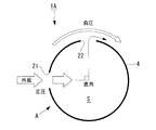
- FIG. 2 is a schematic longitudinal sectional view of the wind turbine generator 1A according to the first embodiment of the present invention
- FIG. 3 is a transverse sectional view taken along line III-III in FIG.
- This wind power generator 1A includes a cooling structure A.
- the inlet 21 and the outlet 22 are provided in the tower 4 having a substantially circular cross-sectional shape as described above.
- the introduction port 21 is an opening that takes outside air as cooling air into the internal space S of the tower 4, and is provided on a portion of the outer surface of the tower 4 that receives a positive pressure by the outside wind.
- the discharge port 22 is an opening through which the cooling air in the internal space S is exhausted to the outside, and is provided in a portion of the outer surface of the tower 4 that receives negative pressure due to external wind.
- the installation location of the wind power generator 1 ⁇ / b> A is considered geographically, and the surface having the best wind per year in the circumferential direction of the outer peripheral surface of the tower 4, that is, the positive pressure due to the external wind is averaged throughout the year.
- the inlet 21 is provided at the highest position, and the outlet 22 is provided at a position perpendicular to the circumferential direction from the inlet 21.
- one discharge port 22 is provided at a position 90 ° away from the introduction port 21.
- two discharge ports 22 are provided on both sides of the introduction port 21.
- An outlet 22 may be provided.
- the shape of the inlet 21 and the outlet 22 is a shape that does not interfere with the strength of the tower 4 as much as possible.
- the introduction port 21 and the discharge port 22 may be formed by forming a plurality of small holes or slits close to each other without forming a single opening. . Thereby, the strength fall of the tower 4 accompanying formation of the inlet 21 and the outlet 22 can be suppressed to the minimum.
- a difference in height is provided between the position of the inlet 21 and the position of the outlet 22.
- the inlet 21 is formed near the lower end of the tower 4, that is, near the ground surface 2 and the electric device 14, and the outlet 22 is formed near the upper end of the tower 4.
- the electric device 14 is disposed between the introduction port 21 and the discharge port 22.
- the cooling structure A configured as described above operates as follows.
- the external wind blows on the wind power generator 1A
- the inlet 21 provided in the portion of the outer peripheral surface of the tower 4 that receives positive pressure by the external wind and the discharge port 22 that receives negative pressure by the external wind.
- a pressure difference is generated in the wind turbine generator 1A, and the wind generator 1A is naturally ventilated without power. That is, outside air is directly introduced into the inside of the tower 4 as cooling air from the introduction port 21, and this cooling air is exchanged for cooling the heat-generating electric device 14 installed in the internal space S of the tower 4.
- the hot air flows toward the discharge port 22 formed upward in accordance with the natural law of convection upward.
- the discharge port 22 is provided at a position perpendicular to the circumferential direction from the position of the introduction port 21 that receives the highest positive pressure by the external wind.
- This position is a negative generated by the external wind. This is where the pressure is almost at its maximum.
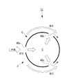
- known data of the pressure distribution on the outer circumference of the cylinder when the circumferential position of the inlet 21 is set to 0 °, the positive pressure acting on the 0 ° position is assumed to be the maximum value +1. Then, the positive pressure changes to a negative pressure as it moves 30 ° and 60 ° in the circumferential direction from here, and the negative pressure becomes less than or equal to the maximum value of ⁇ 1 at a position around 90 °. That is, in absolute value, negative pressure is greater than positive pressure.
- the outside wind is taken into the internal space S of the wind turbine generator 1A (tower 4) from the inlet 21 with a very simple and inexpensive configuration. Then, after the heat-generating electric device 14 is cooled, the hot air can be smoothly discharged from the discharge port 22.
- the introduction port 21 is provided in a portion of the outer peripheral surface of the tower 4 that receives a positive pressure by the outside wind, and the discharge port 22 is provided at a position substantially perpendicular to the circumferential direction from the introduction port 21, so that it acts on the introduction port 21.
- the maximum pressure difference between the positive pressure and the negative pressure acting on the discharge port 22 is ensured, and the outside wind can be efficiently taken in from the introduction port 21 and discharged from the discharge port 22 without using power such as a ventilation fan.
- the electric device 14 and the like can be cooled well without consuming electric power.
- FIG. 5 is a schematic longitudinal sectional view of a wind turbine generator 1B according to the second embodiment of the present invention.
- the wind power generator 1B includes a cooling structure B.
- This cooling structure B differs from the cooling structure A in the first embodiment described above in that the installation height of the introduction port 21 is near the middle portion of the tower 4 and the installation height of the discharge port 22 is the tower 4.
- the other configuration is the same as that of the cooling structure A. That is, the positional relationship between the introduction port 21 and the discharge port 22 in a plan view is as shown in FIG. 3, and the operational effect brought about by this is the same as that of the cooling structure A.
- the height of the inlet 21 is set in the vicinity of the highest position in the range R from the ground surface 2 to the lower end of the rotation locus of the tip 9a of the wind turbine blade 9.
- the speed of the external wind is generally low near the ground surface 2 and tends to increase as the distance from the ground surface 2 increases.
- the introduction port 21 at the above height position that does not overlap the rear part of the rotation locus of the wind turbine blade 9, the ground speed is relatively high. Fast outside wind can be introduced from the introduction port 21 without being affected by the turbulence of the airflow by the wind turbine blades 9, and the inside of the wind turbine generator 1B can be cooled well.
- the height of the discharge port 22 is not necessarily near the lower end of the tower 4, but it is desirable that the heat-generating electrical device 14 is disposed between the introduction port 21 and the discharge port 22. Then, the discharge port 22 is arranged near the lower end of the tower 4 in accordance with the installation position of the electric device 14.
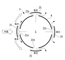
- FIG. 6 is a schematic longitudinal sectional view of a wind turbine generator 1C according to a third embodiment of the present invention
- FIG. 7 is a transverse sectional view taken along line VII-VII in FIG. 6,
- FIG. 8 is VIII in FIG. It is a cross-sectional view along line -VIII.
- the wind power generator 1C includes a cooling structure C.
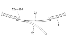
- the introduction port 21 is disposed near the lower end portion of the tower 4, and the discharge ports 22 a to 22 d are disposed near the upper end of the tower 4.
- the introduction port 21 is provided only at one place on the surface of the outer peripheral surface of the tower 4 that is on average the best wind per year, that is, the position where the positive pressure due to the outside wind is highest throughout the year. ing.
- the discharge ports 22a to 22d are provided at a height near the upper end of the tower 4 at, for example, four positions at intervals of 90 ° in the circumferential direction. May be set arbitrarily.
- a saddle member 25 is provided as a negative pressure increasing means for increasing the negative pressure received by the external wind.
- the flange member 25 is a plate-like member that covers the openings of the discharge ports 22a to 22d and is fixed at a predetermined distance from the discharge ports 22a to 22d via stays or brackets (not shown).
- the area of the gutter member 25 is set to be slightly larger than the opening area of the discharge ports 22a to 22d.
- the eaves member 25 is curved along the curved shape of the outer peripheral surface of the tower 4, but may be flat, for example.
- the cooling structure C configured as described above operates as follows.
- the outside wind blows to the wind power generator 1C
- the outside wind blows as it is into the inlet 21 provided at the position where the positive pressure due to the outside wind becomes the highest, and is introduced into the interior of the tower 4 as cooling air, and the electric equipment After the heat generating equipment such as 14 is cooled, the process proceeds from the outlets 22a to 22d provided above.
- the discharge ports 22a to 22d the negative pressure of the outside wind acting on the discharge ports 22a to 22d is increased by providing the flange member 25.
- the position of the discharge port 22a directly facing the outside wind is the place where the highest positive pressure is received by the outside wind as in FIG.
- the provision of the eaves member 25 causes the outside wind to collide with the eaves member 25 without entering the inside of the discharge port 22a, and then to the left and right. And then flows backward along the outer peripheral curved surface of the tower 4 as it is. For this reason, a strong negative pressure is generated between the flange member 25 and the outer peripheral surface of the tower 4, that is, in the vicinity of the discharge port 22 a, thereby sucking the air inside the tower 4 from the discharge port 22 a to the outside.
- the positions where the discharge ports 22b and 22d are provided are perpendicular to the circumferential direction (90 °) from the position of the discharge port 22a that receives the highest positive pressure by the external wind. Since it is provided, it is a place where the negative pressure generated by the flow of the external wind is almost maximized. For this reason, even if there is no saddle member 25, a strong negative pressure acts on the discharge ports 22b and 22d, and an inside air suction action as shown in FIG. 3 is achieved. Further, by providing the flange member 25 here, the flow of the external wind flowing backward along the outer peripheral curved surface of the tower 4 is rectified, and the separation of the air flow in the vicinity of the discharge ports 22b and 22d is prevented. The negative pressure acting on the outlets 22b and 22d is increased.
- the cooling air in the internal space S is sucked out from the discharge ports 22b and 22d so as to be merged with the flow of the outside wind passing by the discharge ports 22b and 22d.
- the inside air is also discharged from the discharge port 22c.
- the discharge ports 22a to 22d are provided at four locations at equal intervals in the circumferential direction, but the present invention is not particularly limited only to the form. Even if the discharge ports 22b and 22d shown in FIG. 7 are provided at a position shifted by 120 ° in the circumferential direction from the position of the discharge port 22a, the discharge ports 22b and 22d are similarly provided by providing the flange member 25. A strong negative pressure can be applied to the surface.
- the flange member 25 at the discharge ports 22a to 22d, the negative pressure of the external wind acting on the discharge ports 22a to 22d can be increased, and the discharge port is located at a position facing the external wind. Since a large amount of inside air can be drawn out from the air inlet 22a, the pressure difference between the inlet 21 and the outlets 22a to 22d is increased, sufficient outside air is introduced from the inlet 21 and the interior space S Can be efficiently discharged from the discharge ports 22a to 22d, and the internal cooling performance of the wind turbine generator 1C can be improved.
- the eaves member 25 has a very simple configuration, there is no concern that the construction cost of the wind power generator 1C will be improved.
- the strength reduction of the tower 4 due to the perforations of the discharge ports 22a to 22d can be reduced.
- the upper and lower ends of the flange member 25 are bent or curved toward the outer peripheral surface of the tower 4, and the distal end portion is fixed to the outer peripheral surface of the tower 4, thereby It is conceivable to form a tunnel shape and to distribute the external air in the circumferential direction inside the tunnel-shaped flange member 25. Thereby, the installation location of the discharge port 22 can be increased without impairing the strength of the tower 4, or the opening area of the discharge port 22 can be increased to improve the cooling efficiency.
- FIG. 10 is a schematic longitudinal sectional view of a wind turbine generator 1D according to the fourth embodiment of the present invention.
- the wind power generator 1D includes a cooling structure D.
- this cooling structure D the difference from the cooling structure C in the third embodiment described above is that the installation location of the introduction port 21 is provided not on the tower 4 but on the front surface of the nacelle 5 and from the four discharge ports 22a. It is only that the installation height of 22d is near the lower end part of the tower 4, and the other structure is the same as that of the cooling structure C.
- the number of the discharge ports 22a to 22d is not necessarily four.
- the inlet 21 is open on the front surface of the nacelle 5 below, for example, a portion where the rotating shaft 12 of the wind turbine blade 9 protrudes, but opens toward the front (windward side). If it exists, you may provide in other places, for example, the side surface of the nacelle 5, an upper surface, etc.
- the circumferential position of the discharge ports 22a to 22d provided on the outer peripheral surface of the tower 4 and the structure, action, effect, etc. of the flange member 25 as the negative pressure increasing means are the same as those of the cooling structure C.
- the introduction port 21 provided in the nacelle 5 is always directed to the windward side in accordance with the control rotation of the nacelle 5, so that the external wind taken from the introduction port 21 is always taken. Maximum amount can be secured.
- the discharge ports 22a to 22d side by providing the flange member 25, the good exhaust action as described above is obtained, so that the pressure difference between the introduction port 21 and the discharge ports 22a to 22d is increased.
- the supply amount of the cooling air supplied to the internal space S of the wind power generator 1D can be increased, and high cooling efficiency can be obtained without power.
- the electric equipment 14 installed at the bottom of the tower 4 but also the heat generating equipment such as the generator 11 installed in the nacelle 5 can be reliably cooled.
- FIG. 11 is a schematic longitudinal sectional view of a wind turbine generator 1E according to a fifth embodiment of the present invention
- FIG. 12 is a transverse sectional view taken along line XII-XII in FIG. 11
- FIG. 13 is XIII in FIG. It is a cross-sectional view along line -XIII.
- the wind power generator 1E includes a cooling structure E.
- this cooling structure E four inlets 21a to 21d are arranged in the vicinity of the lower end of the tower 4 at intervals of, for example, 90 ° in the circumferential direction, and four outlets 22a to 22d are also arranged in the circumferential direction near the upper end of the tower 4. They are arranged at 90 ° intervals.
- Each inlet 21a to 21d is provided with an inner lid member 31 as inlet opening / closing means
- each outlet 22a to 22d is provided with an outer lid member 32 as outlet opening / closing means.
- the number of the introduction ports 21a to 21d and the discharge ports 22a to 22d does not necessarily have to be four, and the number and interval may be arbitrarily set, for example, three at 120 ° intervals.
- the inner lid member 31 is a plate-like member that is curved along the inner peripheral surface of the tower 4 and is formed so that the inlets 21 a to 21 d can be airtightly closed from the inside.
- the inlets 21a to 21d are provided so as to be detachable from the inside.
- the outer lid member 32 is a plate-like member that is curved along the outer peripheral surface of the tower 4 and is formed so as to airtightly close the discharge ports 22a to 22d from the outside.
- the outlets 22a to 22d are provided so as to be separable from the outside.
- the inner lid member 31 has a rod-shaped guide rod 35 fixed vertically at the center thereof, and a stopper plate 36 is fixed to the other end of the guide rod 35.
- a slide pipe 37 is fixed inside the introduction ports 21a to 21d by a stay member (not shown), and a guide rod 35 is inserted into and supported by the slide pipe 37 so as to be slidable in the axial direction. Therefore, the inner lid member 31 can move between the closed position 31a shown in FIG. 14A and the open position 31b shown in FIG. 14B.
- the inner lid member 31 closely contacts the inlets 21a to 21d from the inner side to close the inlets 21a to 21d, and the stopper plate 36 contacts the inner end of the slide pipe 37.
- the inner lid member 31 moves away from the introduction ports 21a to 21d to open the introduction ports 21a to 21d. At this time, the inner lid member 31 abuts against the outer end portion of the slide pipe 37 and the movement is restricted.
- the outer lid member 32 is a slide pipe 37 in which a guide rod 35 fixed to the center thereof is fixed inside the discharge ports 22a to 22d, as shown in FIGS. 15A and 15B.
- the stopper plate 36 is fixed to the other end portion of the guide rod 35.
- the outer side cover member 32 can move between the obstruction
- the outer lid member 32 closely contacts the discharge ports 22a to 22d from the outside to close the discharge ports 22a to 22d.
- the open position 32b the outer lid member 32 is spaced outward from the outlets 22a to 22d to open the outlets 22a to 22d.
- the stopper plate 36 abuts the inner end of the slide pipe 37 and the outer lid member 32 Movement is regulated.
- the inner lid member 31 slides from the closed position 31a to the open position 31b when the pressure outside the inlets 21a to 21d is higher than the inner pressure, and the pressure inside the inlets 21a to 21d is higher than the outer pressure. If the height also rises, it slides from the open position 31b to the closed position 31a.
- the outer lid member 32 slides from the open position 32b to the closed position 32a when the air pressure outside the discharge ports 22a to 22d becomes higher than the air pressure inside, and the air pressure inside the discharge ports 22a to 22d is higher than the air pressure outside. When the height also rises, it slides from the closed position 32a to the open position 32b.
- the sliding operation of the inner lid member 31 and the outer lid member 32 may be naturally moved by being pressed by the atmospheric pressure, but is controlled to open and close according to the atmospheric pressure by using a dedicated driving device and a control device. You may do it.
- the cooling structure E configured as described above operates as follows. For example, when the outside wind blows from the front to the wind power generator 1E, the outside air pressure of the introduction port 21a facing the outside wind among the four introduction ports 21a to 21d provided in the vicinity of the lower end of the tower 4 is outside. Since the pressure is higher than the inner pressure, the inner lid member 31 is pressed by the pressure and slides to the open position 31b, and the introduction port 21a is opened. On the other hand, since the introduction ports 21b and 21d are located at a position 90 ° away from the introduction port 21a in the circumferential direction, negative pressure acts on these positions as the outside wind flows on the surface. Further, a negative pressure acts on the outside of the introduction port 21c.
- the outer lid member 32a has an outer pressure higher than the inner pressure at the outlet 22a facing the outside wind. Is pressed by the atmospheric pressure and slides to the closing position 32a, and the discharge port 22a is closed. Since the discharge ports 22b and 22d are located at a position 90 ° away from the discharge port 22a in the circumferential direction, negative pressure acts on these positions as the outside wind flows on the surface. Negative pressure also acts outside the discharge port 22c.
- the air pressure inside thereof becomes higher than the air pressure outside, and the respective outer lid members 32 slide to the open position 32b, and the discharge ports 22b, 22c, and 22d are opened. The Therefore, the air inside the tower 4 is discharged from the discharge ports 22b, 22c, and 22d except for the discharge port 22a that faces the outside wind.
- the inner lid member 31 and the outer lid member 32 can be simply configured, the cost is not greatly increased.
- the inner lid member 31 and the outer lid member 32 are not limited to the slide type described above, and may have other structures.
- the inner lid member 31 and the outer lid member 32 are configured in a flapper type (reed valve type), whereby the structure can be further simplified.
- FIG. 17 is a schematic longitudinal sectional view of a wind turbine generator 1F according to the sixth embodiment of the present invention.
- the wind power generator 1F includes a cooling structure F.
- This cooling structure F is different from the cooling structure E in the fifth embodiment described above only in that the installation location of the discharge port 22e is provided on the rear surface of the nacelle 5 instead of the tower 4, and from the introduction port 21a.
- the structure of the other parts including 21d is the same as that of the cooling structure E.
- the outlet 22e When the outlet 22e is provided on the rear surface of the nacelle 5, the outlet 22e is always directed to the leeward side of the outside wind according to the rotation of the nacelle 5, and when the outlet 22f is provided on the side surface of the nacelle 5, Since the discharge port 22f is located at a place where a strong negative pressure is generated by the external wind, in any case, a strong negative pressure acts on the outside of the discharge ports 22e and 22f, and the air in the nacelle 5 and thus the internal space S of the tower 4 The effect
- the amount of cooling air supplied from the inlets 21a to 21d to the internal space S of the wind power generator 1F is increased, and the electric equipment 14 installed at the bottom of the tower 4 and the power generation installed in the nacelle 5 are installed.
- the heat generating equipment such as the machine 11 can be effectively cooled.
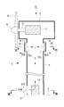
- FIG. 18 is a schematic longitudinal sectional view of a wind turbine generator 1G according to a seventh embodiment of the present invention
- FIG. 19 is a transverse sectional view taken along line XIX-XIX in FIG.
- This wind power generator 1G includes a cooling structure G.
- a cylindrical inner wall 41 is provided inside the tower 4 so that the tower 4 has a double-pipe structure
- an outer space S1 is defined on the outer peripheral side inside the tower 4, and the outer space S1.
- An inner space S ⁇ b> 2 is defined on the inner peripheral side.
- the introduction port 21 is provided so as to communicate with the outer space S1
- the discharge port 22 is provided so as to communicate with the inner space S2.
- the heights of the introduction port 21 and the discharge port 22 are both set in the vicinity of the intermediate portion of the tower 4, but the heights may be different.
- FIG. 19 shows the circumferential positions of the introduction port 21 and the discharge port 22 in plan view.
- the circumferential positions of the inlet port 21 and the outlet port 22 are the same as the cooling structure A in the first embodiment shown in FIG. That is, the introduction port 21 is provided at a position where the positive pressure due to the outside wind is highest, and the discharge port 22 is provided at a position perpendicular to the circumferential direction from the position of the introduction port 21.
- Two outlets 22 may be provided on both sides of the inlet 21.
- the introduction port 21 penetrates the outer wall of the tower 4 and communicates with the outer space S1, and the outside air introduced from the introduction port 21 flows into the outer space S1.
- the discharge port 22 communicates with the inner space S2 through the communication pipe 43, and the air in the inner space S2 is discharged from the discharge port 22 without entering the outer space S1.
- the height of the upper end portion of the inner wall 41 is substantially the same as the height near the upper end of the tower 4, and the outer space S 1 and the inner space S 2 communicate with each other inside the nacelle 5. Since the height of the lower end portion of the inner wall 41 is slightly higher than the lower end portion of the tower 4, the outer space S ⁇ b> 1 and the inner space S ⁇ b> 2 communicate with each other in the vicinity of the lower end portion of the tower 4. Thus, the outer space S1 and the inner space S2 communicate with each other at a position away from the position where the introduction port 21 and the discharge port 22 are provided.
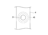
- an arc-shaped filter member 45 is provided around the introduction port 21.
- the filter member 45 is located on the downstream side of the introduction port 21 and functions as a foreign matter removing unit that removes foreign matters such as moisture, salt, and dust contained in the outside air introduced from the introduction port 21.
- the shape of the filter member 45 is not limited to an arc shape.
- the cross section of the filter member 45 shown in FIG. 18 is directly extended in the circumferential direction of the outer space S1 so as to have a large ring shape in plan view, and the introduction port 21 is sandwiched between the upper and lower filter members. May be.
- the cooling structure G configured as described above operates as follows.
- the external wind blows on the wind power generator 1G
- the external wind is first introduced into the outer space S1 as cooling air from the inlet 21 provided on the outer peripheral surface of the tower 4 that receives a positive pressure by the external wind.
- the outside wind flows in the vertical direction and the circumferential direction in the outer space S ⁇ b> 1 after removing foreign matters such as moisture, salt, and dust when passing through the filter member 45.
- the air that has flowed downward in the outer space S1 enters the inner space S2 while diverting the lower end of the inner wall 41 and changing the flow direction upward, and then cools the heat-generating electrical device 14 and moves upward. It flows and is discharged from the discharge port 22 to the outside. Since the discharge port 22 is provided in a place where the negative pressure generated by the external wind is substantially maximized, a large pressure difference is generated between the introduction port 21 and the discharge port 22, and air in the inner space S ⁇ b> 2 is eliminated. It can ventilate efficiently with power.
- the distance from the inlet 21 to the outlet 22 is increased, the direction of the airflow is changed between the outer space S1 and the inner space S2, and the outer space S1 that is a cylindrical space. Since centrifugal force acts on the airflow flowing in the circumferential direction in the interior, foreign substances such as moisture, salt, and dust contained in the external wind can be mainly spontaneously dropped in the outer space S1 and separated from the airflow, and the inlet 21 In combination with the provision of the filter member 45, it is possible to reliably prevent foreign matter from entering the inner space S2 and to effectively protect the internal devices.
- the filter member 45 may be simple and may not be provided in some cases, a sufficient amount of outside wind is introduced from the inlet 21 by avoiding or reducing pressure loss due to the filter member 45, and the wind turbine generator.
- the cooling efficiency inside 1G can be increased. Since the tower 4 has a double tube structure by providing the inner wall 41 inside the tower 4, the strength of the tower 4 can be increased.
- FIG. 21 is a schematic longitudinal sectional view of a wind turbine generator 1H according to an eighth embodiment of the present invention
- FIG. 22 is a transverse sectional view taken along line XXII-XXII in FIG. 21, and
- FIG. 23 is XXIII in FIG. It is a cross-sectional view along line -XXIII.
- the wind power generator 1H includes a cooling structure H.
- this cooling structure H similarly to the above-described cooling structure G, a cylindrical inner wall 41 is provided inside the tower 4 so that the tower 4 has a double-pipe structure. An inner space S2 is defined.
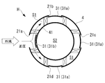
- four introduction ports 21 a to 21 d are arranged at intervals of 90 ° in the circumferential direction at a height slightly below the middle portion of the tower 4, and at a height slightly above the middle portion of the tower 4.
- the two outlets 22a to 22d are also arranged at 90 ° intervals in the circumferential direction.
- the inlets 21a to 21d penetrate the outer wall of the tower 4 and communicate with the outer space S1, and the outside air introduced from the inlets 21a to 21d flows into the outer space S1.
- the discharge ports 22a to 22d communicate with the inner space S2 through the communication pipe 43, and the air in the inner space S2 is discharged from the discharge ports 22a to 22d without entering the outer space S1.
- Each inlet 21a to 21d is provided with an inner lid member 31 as an inlet opening / closing means, and each of the outlets 22a to 22d is provided with an outer lid member 32 as an outlet opening / closing means.
- the configurations and actions of the inner lid member 31 and the outer lid member 32 are the same as those of the cooling structure E according to the fifth embodiment.
- Each inlet 21a to 21d is provided with a filter member 45 similar to the cooling structure G according to the seventh embodiment.
- the cooling structure H configured as described above operates as follows. For example, when outside wind is blown from the front to the wind power generator 1H, the outside wind out of the four inlets 21a to 21d provided on the outer peripheral surface of the tower 4 is the same as the cooling structure E in the fifth embodiment. Only the inner lid member 31 of the introduction port 21a that directly faces is opened (becomes an open position 31b), and the inner lid members 31 of the other three introduction ports 21b, 21c, and 21d are closed (becomes the closed position 31a). Therefore, the introduction ports 21b, 21c, and 21d are closed. For this reason, the outside wind flows into the outer space S1 only from the introduction port 21a.
- the inflowing outside air flows in the up and down direction and the circumferential direction in the outer space S ⁇ b> 1 after removing foreign matters such as moisture, salt and dust when passing through the filter member 45.
- the air that has flowed downward in the outer space S1 enters the inner space S2 while diverting the lower end portion of the inner wall 41 and changing the flow direction upward, and flows upward after cooling the heat-generating electrical device 14.
- the cooling structure E in 5th Embodiment among the four discharge ports 22a to 22d provided in the outer peripheral surface of the tower 4, only the outer side cover member 32 of the discharge port 22a which opposes an external wind is obstruct
- this cooling structure H as in the cooling structure G in the seventh embodiment, foreign substances such as moisture, salt, and dust contained in the external wind are mainly naturally dropped in the outer space S1 to be separated from the air flow, Equipment can be protected. Moreover, similarly to the cooling structure E, it is possible to reduce a problem that the cooling efficiency of the wind power generator 1E is lowered depending on the wind direction, and to obtain a stable cooling action throughout the year.
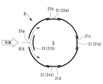
- FIG. 24 is a schematic longitudinal sectional view of a wind turbine generator 1J according to the ninth embodiment of the present invention
- FIG. 25 is a transverse sectional view taken along line XXV-XXV in FIG.
- the wind power generator 1J includes a cooling structure J.
- this cooling structure J for example, three vent holes 48a to 48c are formed at intervals of 120 ° in the vicinity of the lower end of the tower 4 along the circumferential direction of the outer peripheral surface of the tower 4, for example.
- These vents 48a to 48c serve as inlets for taking outside wind into the internal space S of the tower 4 or exhaust ports for exhausting air in the internal space S to the outside according to the wind direction.
- vent holes 48a to 48c are provided so as to surround the periphery of a heat generating device such as the electric device 14 installed in the lower part of the tower 4, but are not necessarily provided at the same height. You may give a height difference between 48a to 48c.
- the circumferential position and quantity of each vent 48a to 48c do not necessarily have to be three at 120 ° intervals, and may be three or more, for example.
- the cooling structure J configured as described above operates as follows. For example, when the outside wind blows on the wind power generator 1J, as shown in FIG. 25, if the outside wind is in the direction of the wind hitting the vent 48a, the vent 48a receives a positive pressure by the outside wind and becomes an introduction port. Is directly introduced into the interior of the tower 4 as cooling air from the vent 48a to cool the electric device 14. On the other hand, the vent holes 48b and 48c are exhausted because they receive negative pressure due to the outside wind, and the air in the internal space S is exhausted to the outside from here.
- vent 48b For example, if the direction of the wind from which the outside wind hits the vent 48b is changed, the vent 48b is now an inlet and the vents 48a and 48c are outlets. If the direction of the wind that the outside wind hits the vent 48c is changed, the vent 48c serves as an inlet and the vents 48a and 48b serve as outlets.
- one of the plurality of vent holes 48a to 48c serves as an introduction port and the other serves as a discharge port. Therefore, the electric device 14 is always excellent regardless of the wind direction. Can be cooled.
- the present invention is not limited to the aspects of the first to ninth embodiments described above.
Landscapes
- Engineering & Computer Science (AREA)
- Physics & Mathematics (AREA)
- Thermal Sciences (AREA)
- Life Sciences & Earth Sciences (AREA)
- Sustainable Development (AREA)
- Sustainable Energy (AREA)
- Chemical & Material Sciences (AREA)
- Combustion & Propulsion (AREA)
- Mechanical Engineering (AREA)
- General Engineering & Computer Science (AREA)
- Wind Motors (AREA)
Priority Applications (3)
| Application Number | Priority Date | Filing Date | Title |
|---|---|---|---|
| EP11800953.9A EP2589806A4 (en) | 2010-06-30 | 2011-06-30 | WIND POWER GENERATOR |
| US13/242,771 US20120032448A1 (en) | 2010-06-30 | 2011-09-23 | Wind turbine generator |
| US13/549,173 US8672628B2 (en) | 2010-06-30 | 2012-07-13 | Wind turbine generator |
Applications Claiming Priority (2)
| Application Number | Priority Date | Filing Date | Title |
|---|---|---|---|
| JP2010150473A JP5449060B2 (ja) | 2010-06-30 | 2010-06-30 | 風力発電装置 |
| JP2010-150473 | 2010-06-30 |
Related Parent Applications (1)
| Application Number | Title | Priority Date | Filing Date |
|---|---|---|---|
| US13/242,771 Division US20120032448A1 (en) | 2010-06-30 | 2011-09-23 | Wind turbine generator |
Related Child Applications (2)
| Application Number | Title | Priority Date | Filing Date |
|---|---|---|---|
| US13/242,771 Continuation US20120032448A1 (en) | 2010-06-30 | 2011-09-23 | Wind turbine generator |
| US13/549,173 Continuation US8672628B2 (en) | 2010-06-30 | 2012-07-13 | Wind turbine generator |
Publications (1)
| Publication Number | Publication Date |
|---|---|
| WO2012002491A1 true WO2012002491A1 (ja) | 2012-01-05 |
Family
ID=45402194
Family Applications (1)
| Application Number | Title | Priority Date | Filing Date |
|---|---|---|---|
| PCT/JP2011/065040 Ceased WO2012002491A1 (ja) | 2010-06-30 | 2011-06-30 | 風力発電装置 |
Country Status (4)
| Country | Link |
|---|---|
| US (2) | US20120032448A1 (https=) |
| EP (1) | EP2589806A4 (https=) |
| JP (1) | JP5449060B2 (https=) |
| WO (1) | WO2012002491A1 (https=) |
Cited By (3)
| Publication number | Priority date | Publication date | Assignee | Title |
|---|---|---|---|---|
| CN102705179A (zh) * | 2012-06-08 | 2012-10-03 | 华锐风电科技(江苏)有限公司 | 微正压发生装置 |
| US20140318060A1 (en) * | 2011-09-09 | 2014-10-30 | Areva Wind Gmbh | Wind turbine with circumferential air guiding tower wall reinforcement |
| EP2853734A1 (en) | 2013-09-26 | 2015-04-01 | Mitsubishi Heavy Industries, Ltd. | Ventilation system for a renewable energy power generating apparatus |
Families Citing this family (16)
| Publication number | Priority date | Publication date | Assignee | Title |
|---|---|---|---|---|
| DK2182205T3 (en) * | 2008-10-28 | 2016-06-06 | Siemens Ag | Wind turbine device and method for adjusting a wind turbine according to the wind direction |
| JP5455508B2 (ja) * | 2009-08-28 | 2014-03-26 | 三菱重工業株式会社 | 風力発電用風車 |
| JP5595057B2 (ja) * | 2010-02-08 | 2014-09-24 | 三菱重工業株式会社 | 風力発電装置 |
| EP2535575A4 (en) * | 2010-02-08 | 2014-04-30 | Mitsubishi Heavy Ind Ltd | WIND ENERGY GENERATING DEVICE |
| JP5449060B2 (ja) * | 2010-06-30 | 2014-03-19 | 三菱重工業株式会社 | 風力発電装置 |
| EP2568169B2 (en) | 2011-09-09 | 2021-11-10 | Siemens Gamesa Renewable Energy Deutschland GmbH | Wind turbine with tower climatisation system using outside air |
| CA2877493C (en) * | 2012-07-24 | 2020-08-25 | Natera, Inc. | Highly multiplex pcr methods and compositions |
| JP6383562B2 (ja) * | 2014-04-23 | 2018-08-29 | 株式会社日立製作所 | 風力発電設備 |
| JP6368559B2 (ja) | 2014-06-27 | 2018-08-01 | 株式会社日立製作所 | 風力発電装置 |
| CN104632537B (zh) * | 2015-01-30 | 2018-05-04 | 北京金风科创风电设备有限公司 | 风力发电机组的冷却装置、冷却系统和风力发电机组 |
| CN105089943B (zh) * | 2015-08-10 | 2019-02-15 | 北京金风科创风电设备有限公司 | 风力发电机组散热系统和风力发电机组 |
| US10552320B2 (en) * | 2016-04-01 | 2020-02-04 | Intel Corporation | Using a projected out of memory score to selectively terminate a process without transitioning to a background mode |
| US10954922B2 (en) | 2019-06-10 | 2021-03-23 | General Electric Company | System and method for cooling a tower of a wind turbine |
| EP4083413B1 (en) * | 2021-04-28 | 2024-05-15 | General Electric Renovables España S.L. | Back-up power supply for wind turbines |
| WO2023276016A1 (ja) * | 2021-06-29 | 2023-01-05 | 株式会社リアムウィンド | 発電装置、上昇気流発生装置、発電方法及び上昇気流増速方法 |
| CN114060236A (zh) * | 2021-12-17 | 2022-02-18 | 东方电气(天津)风电叶片工程有限公司 | 一种风电叶片用均压排气装置 |
Citations (4)
| Publication number | Priority date | Publication date | Assignee | Title |
|---|---|---|---|---|
| JP2000161197A (ja) * | 1998-11-21 | 2000-06-13 | Wilhelm Groppel | 風力発電機 |
| JP2001167613A (ja) * | 1999-12-13 | 2001-06-22 | Matsushita Electric Works Ltd | 照明灯具用ポール |
| JP2009531579A (ja) * | 2006-03-25 | 2009-09-03 | クリッパー・ウィンドパワー・テクノロジー・インコーポレーテッド | 風力タービンのための熱管理システム |
| WO2010013362A1 (ja) * | 2008-07-28 | 2010-02-04 | 三菱重工業株式会社 | 風力発電装置 |
Family Cites Families (10)
| Publication number | Priority date | Publication date | Assignee | Title |
|---|---|---|---|---|
| WO1999030031A1 (de) * | 1997-12-08 | 1999-06-17 | Siemens Aktiengesellschaft | Windkraftanlage und verfahren zur kühlung eines generators einer windkraftanlage |
| NL1013129C2 (nl) * | 1999-09-24 | 2001-03-27 | Lagerwey Windturbine B V | Windmolen. |
| GB0118996D0 (en) * | 2001-08-03 | 2001-09-26 | Hansen Transmissions Int | Drive Assembly |
| DE102004061391B4 (de) * | 2004-12-21 | 2010-11-11 | Repower Systems Ag | Temperaturregelung in einer Windenergieanlage |
| US7168251B1 (en) | 2005-12-14 | 2007-01-30 | General Electric Company | Wind energy turbine |
| WO2008098574A1 (en) * | 2007-02-12 | 2008-08-21 | Vestas Wind Systems A/S | A wind turbine, a method for establishing at least one aperture in the spinner on the hub of a wind turbine rotor and use of a wind turbine |
| US8047774B2 (en) * | 2008-09-11 | 2011-11-01 | General Electric Company | System for heating and cooling wind turbine components |
| US7843080B2 (en) * | 2009-05-11 | 2010-11-30 | General Electric Company | Cooling system and wind turbine incorporating same |
| JP5449060B2 (ja) * | 2010-06-30 | 2014-03-19 | 三菱重工業株式会社 | 風力発電装置 |
| BRPI1100020A2 (pt) * | 2011-01-28 | 2016-05-03 | Mitsubishi Heavy Ind Ltd | gerador de turbina eólica. |
-
2010
- 2010-06-30 JP JP2010150473A patent/JP5449060B2/ja not_active Expired - Fee Related
-
2011
- 2011-06-30 WO PCT/JP2011/065040 patent/WO2012002491A1/ja not_active Ceased
- 2011-06-30 EP EP11800953.9A patent/EP2589806A4/en not_active Withdrawn
- 2011-09-23 US US13/242,771 patent/US20120032448A1/en not_active Abandoned
-
2012
- 2012-07-13 US US13/549,173 patent/US8672628B2/en not_active Expired - Fee Related
Patent Citations (4)
| Publication number | Priority date | Publication date | Assignee | Title |
|---|---|---|---|---|
| JP2000161197A (ja) * | 1998-11-21 | 2000-06-13 | Wilhelm Groppel | 風力発電機 |
| JP2001167613A (ja) * | 1999-12-13 | 2001-06-22 | Matsushita Electric Works Ltd | 照明灯具用ポール |
| JP2009531579A (ja) * | 2006-03-25 | 2009-09-03 | クリッパー・ウィンドパワー・テクノロジー・インコーポレーテッド | 風力タービンのための熱管理システム |
| WO2010013362A1 (ja) * | 2008-07-28 | 2010-02-04 | 三菱重工業株式会社 | 風力発電装置 |
Non-Patent Citations (1)
| Title |
|---|
| See also references of EP2589806A4 * |
Cited By (3)
| Publication number | Priority date | Publication date | Assignee | Title |
|---|---|---|---|---|
| US20140318060A1 (en) * | 2011-09-09 | 2014-10-30 | Areva Wind Gmbh | Wind turbine with circumferential air guiding tower wall reinforcement |
| CN102705179A (zh) * | 2012-06-08 | 2012-10-03 | 华锐风电科技(江苏)有限公司 | 微正压发生装置 |
| EP2853734A1 (en) | 2013-09-26 | 2015-04-01 | Mitsubishi Heavy Industries, Ltd. | Ventilation system for a renewable energy power generating apparatus |
Also Published As
| Publication number | Publication date |
|---|---|
| EP2589806A1 (en) | 2013-05-08 |
| US20120032448A1 (en) | 2012-02-09 |
| US20120299307A1 (en) | 2012-11-29 |
| EP2589806A4 (en) | 2014-04-23 |
| JP5449060B2 (ja) | 2014-03-19 |
| JP2012013002A (ja) | 2012-01-19 |
| US8672628B2 (en) | 2014-03-18 |
Similar Documents
| Publication | Publication Date | Title |
|---|---|---|
| JP5449060B2 (ja) | 風力発電装置 | |
| JP5463218B2 (ja) | 風力発電装置 | |
| US8476784B2 (en) | Wind turbine generating apparatus | |
| JP5211244B2 (ja) | 風力発電装置 | |
| JP5204216B2 (ja) | 風力発電装置 | |
| JP5595057B2 (ja) | 風力発電装置 | |
| JP2012013002A5 (https=) | ||
| JP5404764B2 (ja) | 風力発電装置 | |
| TWI630316B (zh) | 風力發電裝置 | |
| JP6357307B2 (ja) | 風力発電設備 | |
| KR20110114427A (ko) | 풍력 발전 장치 | |
| JP6074033B2 (ja) | 風力発電設備 | |
| JP2018109412A (ja) | 風力発電設備 |
Legal Events
| Date | Code | Title | Description |
|---|---|---|---|
| 121 | Ep: the epo has been informed by wipo that ep was designated in this application |
Ref document number: 11800953 Country of ref document: EP Kind code of ref document: A1 |
|
| WWE | Wipo information: entry into national phase |
Ref document number: 2011800953 Country of ref document: EP |
|
| NENP | Non-entry into the national phase |
Ref country code: DE |