WO2012002491A1 - 風力発電装置 - Google Patents
風力発電装置 Download PDFInfo
- Publication number
- WO2012002491A1 WO2012002491A1 PCT/JP2011/065040 JP2011065040W WO2012002491A1 WO 2012002491 A1 WO2012002491 A1 WO 2012002491A1 JP 2011065040 W JP2011065040 W JP 2011065040W WO 2012002491 A1 WO2012002491 A1 WO 2012002491A1
- Authority
- WO
- WIPO (PCT)
- Prior art keywords
- wind
- tower
- discharge port
- power generator
- introduction port
- Prior art date
- Legal status (The legal status is an assumption and is not a legal conclusion. Google has not performed a legal analysis and makes no representation as to the accuracy of the status listed.)
- Ceased
Links
Images














Classifications
-
- F—MECHANICAL ENGINEERING; LIGHTING; HEATING; WEAPONS; BLASTING
- F03—MACHINES OR ENGINES FOR LIQUIDS; WIND, SPRING, OR WEIGHT MOTORS; PRODUCING MECHANICAL POWER OR A REACTIVE PROPULSIVE THRUST, NOT OTHERWISE PROVIDED FOR
- F03D—WIND MOTORS
- F03D80/00—Details, components or accessories not provided for in groups F03D1/00 - F03D17/00
- F03D80/60—Cooling or heating of wind motors
-
- F—MECHANICAL ENGINEERING; LIGHTING; HEATING; WEAPONS; BLASTING
- F05—INDEXING SCHEMES RELATING TO ENGINES OR PUMPS IN VARIOUS SUBCLASSES OF CLASSES F01-F04
- F05B—INDEXING SCHEME RELATING TO WIND, SPRING, WEIGHT, INERTIA OR LIKE MOTORS, TO MACHINES OR ENGINES FOR LIQUIDS COVERED BY SUBCLASSES F03B, F03D AND F03G
- F05B2240/00—Components
- F05B2240/90—Mounting on supporting structures or systems
- F05B2240/91—Mounting on supporting structures or systems on a stationary structure
- F05B2240/912—Mounting on supporting structures or systems on a stationary structure on a tower
-
- F—MECHANICAL ENGINEERING; LIGHTING; HEATING; WEAPONS; BLASTING
- F05—INDEXING SCHEMES RELATING TO ENGINES OR PUMPS IN VARIOUS SUBCLASSES OF CLASSES F01-F04
- F05B—INDEXING SCHEME RELATING TO WIND, SPRING, WEIGHT, INERTIA OR LIKE MOTORS, TO MACHINES OR ENGINES FOR LIQUIDS COVERED BY SUBCLASSES F03B, F03D AND F03G
- F05B2260/00—Function
- F05B2260/60—Fluid transfer
- F05B2260/64—Aeration, ventilation, dehumidification or moisture removal of closed spaces
-
- Y—GENERAL TAGGING OF NEW TECHNOLOGICAL DEVELOPMENTS; GENERAL TAGGING OF CROSS-SECTIONAL TECHNOLOGIES SPANNING OVER SEVERAL SECTIONS OF THE IPC; TECHNICAL SUBJECTS COVERED BY FORMER USPC CROSS-REFERENCE ART COLLECTIONS [XRACs] AND DIGESTS
- Y02—TECHNOLOGIES OR APPLICATIONS FOR MITIGATION OR ADAPTATION AGAINST CLIMATE CHANGE
- Y02E—REDUCTION OF GREENHOUSE GAS [GHG] EMISSIONS, RELATED TO ENERGY GENERATION, TRANSMISSION OR DISTRIBUTION
- Y02E10/00—Energy generation through renewable energy sources
- Y02E10/70—Wind energy
- Y02E10/72—Wind turbines with rotation axis in wind direction
-
- Y—GENERAL TAGGING OF NEW TECHNOLOGICAL DEVELOPMENTS; GENERAL TAGGING OF CROSS-SECTIONAL TECHNOLOGIES SPANNING OVER SEVERAL SECTIONS OF THE IPC; TECHNICAL SUBJECTS COVERED BY FORMER USPC CROSS-REFERENCE ART COLLECTIONS [XRACs] AND DIGESTS
- Y02—TECHNOLOGIES OR APPLICATIONS FOR MITIGATION OR ADAPTATION AGAINST CLIMATE CHANGE
- Y02E—REDUCTION OF GREENHOUSE GAS [GHG] EMISSIONS, RELATED TO ENERGY GENERATION, TRANSMISSION OR DISTRIBUTION
- Y02E10/00—Energy generation through renewable energy sources
- Y02E10/70—Wind energy
- Y02E10/728—Onshore wind turbines
Definitions
- the present invention relates to a wind power generator that cools the heat generated by the equipment during operation by introducing outside air.
- a standard wind turbine generator is a device that generates electricity by driving a generator by rotating a rotor head equipped with wind turbine blades by receiving wind force and increasing the speed of the rotation by a gearbox.
- the rotor head is installed on a tower erected on the ground or the like and attached to the end of a nacelle capable of yaw rotation, and is supported so as to be rotatable around a substantially horizontal lateral rotation axis. .
- a steel monopole type using a cylindrical tower shell is often adopted, and the base plate provided at the lower end of the tower shell is fixed to the foundation of the reinforced concrete with an anchor bolt. It has a structure.
- heat generators such as converters and transformers are installed inside such wind turbine generators. To maintain stable operation, these electrical devices must be installed. It needs to be properly cooled.
- a cooling fan installed in a tower or nacelle to cool externally heated electric equipment by forcibly introducing external cold air.
- a coolant such as water or oil is circulated inside a heat-generating electrical device with a circulation pump, and the coolant supplied for cooling is heat-exchanged with a heat exchanger.
- a cooling structure that dissipates the exhaust heat to the outside is known.
- the tower When the tower is provided with an inlet for taking in outside air and an outlet for exhausting the internal air, the number of these openings and the opening area must be kept to the minimum necessary to ensure the strength of the tower.
- the present invention has been made in view of the above circumstances, and with a simple and inexpensive configuration, it is possible to introduce sufficient outside wind while suppressing power consumption, and heat generated in the nacelle or tower.
- An object of the present invention is to provide a wind turbine generator capable of cooling an electrical device with good characteristics.
- the present invention employs the following means. That is, in the wind turbine generator according to one aspect of the present invention, the rotor head that rotates by receiving wind from the wind turbine blades drives a generator installed inside the nacelle to generate electric power, and the nacelle is at the upper end of the tower.
- the wind turbine generator installed in the section an inlet for taking the external wind into the internal space of the wind turbine generator is provided at a portion of the outer surface of the tower or the nacelle that receives positive pressure by the external wind, A discharge port for discharging the cooling air in the internal space to the outside is provided in a portion of the outer peripheral surface of the nacelle that receives a negative pressure by the external wind.
- the inlet provided on the outer peripheral surface of the tower or the nacelle to receive positive pressure by the external wind, and also negative pressure by the external wind. Since a pressure difference is generated between the outlet and the outlet, the wind generator can be ventilated without power. In other words, the outside wind taken from the inlet is made to flow inside the wind power generator as cooling air, and the exothermic electrical equipment installed inside the wind generator is cooled well and then discharged from the outlet to the outside. can do.
- a heat generating device may be disposed between the introduction port and the discharge port. Thereby, a heat-emitting device can be cooled favorably.
- the introduction port when the introduction port and the discharge port are provided in the tower, the introduction port is provided at a position where the positive pressure due to the external wind is highest in the circumferential direction of the outer peripheral surface thereof.
- the discharge port may be provided at a position substantially perpendicular to the circumferential direction from the position of the introduction port.
- the inlet is provided at a position where the positive pressure due to the external wind is highest on the outer peripheral surface of the tower, and the outlet provided at a position substantially perpendicular to the circumferential direction from the position of the inlet Since the largest negative pressure acts when the outside wind flows along the outer peripheral surface of the tower, the pressure difference between the positive pressure applied to the inlet and the negative pressure applied to the outlet is maximized. For this reason, the outside wind is efficiently taken into the wind power generator from the introduction port, and the inside air that has cooled the inside of the wind power generator is efficiently discharged to the outside from the discharge port, thereby increasing the cooling efficiency.
- the wind power generator according to the above aspect may have a height difference between the position of the introduction port and the position of the discharge port.
- the height of the wind turbine generator is within a range from a ground surface on which the tower is erected to a lower end of a rotation locus of the wind turbine blade tip. It may be set near the highest position.
- the ground speed of the outside wind is low near the ground surface where the tower is erected and the turbulence of the airflow occurs due to the rotation of the wind turbine blades at the rear of the wind turbine blades.
- By setting it near the highest position in the range up to the lower end of the rotation trajectory at the tip of the blade it is possible to introduce outside wind with a high ground speed from the inlet without being affected by air current disturbance.
- the inside of the power generator can be cooled well.
- the wind power generator according to the above aspect may be provided with negative pressure increasing means for increasing the negative pressure received by the outside wind at the discharge port. Therefore, since the negative pressure acting on the discharge port is increased, the air inside the wind turbine generator can be efficiently discharged from the discharge port, and the cooling efficiency inside the wind turbine generator can be enhanced.
- the negative pressure increasing means may be a gutter member that covers the opening of the discharge port and is separated from the discharge port by a predetermined distance. According to this configuration, the negative pressure increasing means can be configured very simply.
- the inlet is provided with an inlet opening / closing means that opens when the outer pressure is higher than the inner pressure, and closes when the inner pressure is higher than the outer pressure. It is good as well.
- the outer pressure is higher than the inner pressure.
- the inlet opening / closing means opens, and at the other inlets, the outside air pressure becomes lower than the inside air pressure, so that the inlet opening / closing means closes.
- the outside wind is efficiently introduced and the outside wind once introduced is prevented from escaping from other inlets. Therefore, the pressure difference between the inlet and the outlet can be increased, and a sufficient amount of outside wind can be sent into the wind power generator to increase the cooling efficiency inside the wind power generator.
- the discharge port is provided with a discharge port opening / closing means that is closed when the outer pressure is higher than the inner pressure and opens when the inner pressure is higher than the outer pressure. It is good as well.
- the outer pressure is higher than the inner pressure.
- the discharge port opening / closing means is closed, and at the other discharge ports, the discharge pressure opening / closing means is opened because the outside air pressure becomes lower than the inside pressure. For this reason, the inside air is efficiently discharged, and a relatively large amount of outside wind can be taken from the introduction port to increase the cooling efficiency inside the wind turbine generator.
- the tower has a double pipe structure, the introduction port is provided so as to communicate with either the outer space or the inner space, and the tower is communicated with the other space.
- a discharge port may be provided so that the outer space and the inner space communicate with each other at a position away from the introduction port and the discharge port.
- the distance from the inlet to the outlet becomes longer, the direction of the airflow changes between the outer space and the inner space, and the inside of the outer space, which is a cylindrical space, in the circumferential direction. Since centrifugal force acts on the flowing airflow, foreign substances such as moisture, salt, and dust contained in the external wind can be naturally dropped mainly in the outer space and separated from the airflow. Since it does not have to be provided, or even if it is provided, a simple one can be used. Therefore, a sufficient amount of outside air can be taken in from the introduction port to increase the cooling efficiency inside the wind turbine generator.
- the wind power generator according to the above aspect may be provided with a foreign matter removing means for removing foreign matter contained in the outside air introduced from the introduction port on the downstream side of the introduction port. In this way, it is possible to remove foreign matters such as moisture, salt, and dust contained in the external wind and maintain the soundness of the internal device.
- vent holes are provided along the circumferential direction of the outer peripheral surface, and these vent holes are arranged in the wind direction. Accordingly, the inlet or the outlet may be used. In such a case, the inside of the tower can always be cooled satisfactorily regardless of the direction of the outside wind.
- the wind turbine generator according to the present invention, by using the pressure difference generated between the inlet and the outlet, a simple and inexpensive configuration can be used while suppressing power consumption and sufficient power consumption.
- the wind can be introduced, and the heat generating electrical equipment installed in the nacelle or the tower can be cooled well.
- FIG. 1 is a schematic longitudinal sectional view of a wind turbine generator according to a first embodiment of the present invention.
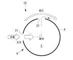
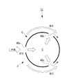
- FIG. 3 is a transverse sectional view taken along line III-III in FIG. 2. It is a figure which shows the pressure distribution in a tower outer peripheral surface with a graph.
- It is a schematic longitudinal cross-sectional view of the wind power generator concerning 2nd Embodiment of this invention. It is a schematic longitudinal cross-sectional view of the wind power generator which concerns on 3rd Embodiment of this invention. It is a cross-sectional view which follows the VII-VII line of FIG. It is a cross-sectional view which follows the VIII-VIII line of FIG.
- FIG. 12 is a transverse sectional view taken along line XII-XII in FIG. 11. It is a cross-sectional view along the XIII-XIII line of FIG. It is a cross-sectional view which shows the 1st structural example of an inlet opening / closing means, and shows the state which has an inner side cover member in a blockade position.
- FIG. 25 is a transverse sectional view taken along line XXV-XXV in FIG. 24.
- FIG. 1 is a side view showing an example of a wind power generator to which cooling structures A to H in each embodiment described later can be applied.
- This wind power generator 1 includes a tower 4 erected on a reinforced concrete foundation 3 installed on the ground surface 2, a nacelle 5 installed at the upper end of the tower 4, and a substantially horizontal lateral rotation. And a rotor head 6 that is rotatably supported around the axis and is provided on the front end side of the nacelle 5.
- the tower 4 is a steel tube monopole type, and its cross-sectional shape is substantially circular.
- a base plate 7 made of, for example, a steel plate is fixed to the lower end portion of the tower 4, and the base plate 7 is fastened and fixed to the foundation 3 with a number of anchor bolts 8.
- a plurality of (for example, three) wind turbine blades 9 extending in the radial direction are attached to the rotor head 6.
- a generator 11 is accommodated in the nacelle 5, and the rotating shaft 12 of the rotor head 6 generates power. It is connected to the main shaft of the machine 11 through a gearbox or the like. For this reason, the wind force of the external wind which hits the windmill blade 9 is converted into a rotational force that rotates the rotor head 6 and the rotating shaft 12, and the generator 11 is driven to generate power.
- the nacelle 5 can be swung in the horizontal direction at the upper end of the tower 4 together with the wind turbine blades 9, and is controlled by a driving device and a control device (not shown) so that the nacelle 5 is always directed efficiently in the windward direction.
- an electrical device 14 that cannot be exposed to external wind and rain is installed. Examples of the electric device 14 include a heat generating device such as a converter and a transformer.
- the internal space S of the tower 4 is in a closed room shape, the internal space is defined by the cooling structures A to J in the embodiments described below. The heat of the electric equipment 14 installed in S is cooled.
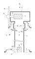
- FIG. 2 is a schematic longitudinal sectional view of the wind turbine generator 1A according to the first embodiment of the present invention
- FIG. 3 is a transverse sectional view taken along line III-III in FIG.
- This wind power generator 1A includes a cooling structure A.
- the inlet 21 and the outlet 22 are provided in the tower 4 having a substantially circular cross-sectional shape as described above.
- the introduction port 21 is an opening that takes outside air as cooling air into the internal space S of the tower 4, and is provided on a portion of the outer surface of the tower 4 that receives a positive pressure by the outside wind.
- the discharge port 22 is an opening through which the cooling air in the internal space S is exhausted to the outside, and is provided in a portion of the outer surface of the tower 4 that receives negative pressure due to external wind.
- the installation location of the wind power generator 1 ⁇ / b> A is considered geographically, and the surface having the best wind per year in the circumferential direction of the outer peripheral surface of the tower 4, that is, the positive pressure due to the external wind is averaged throughout the year.
- the inlet 21 is provided at the highest position, and the outlet 22 is provided at a position perpendicular to the circumferential direction from the inlet 21.
- one discharge port 22 is provided at a position 90 ° away from the introduction port 21.
- two discharge ports 22 are provided on both sides of the introduction port 21.
- An outlet 22 may be provided.
- the shape of the inlet 21 and the outlet 22 is a shape that does not interfere with the strength of the tower 4 as much as possible.
- the introduction port 21 and the discharge port 22 may be formed by forming a plurality of small holes or slits close to each other without forming a single opening. . Thereby, the strength fall of the tower 4 accompanying formation of the inlet 21 and the outlet 22 can be suppressed to the minimum.
- a difference in height is provided between the position of the inlet 21 and the position of the outlet 22.
- the inlet 21 is formed near the lower end of the tower 4, that is, near the ground surface 2 and the electric device 14, and the outlet 22 is formed near the upper end of the tower 4.
- the electric device 14 is disposed between the introduction port 21 and the discharge port 22.
- the cooling structure A configured as described above operates as follows.
- the external wind blows on the wind power generator 1A
- the inlet 21 provided in the portion of the outer peripheral surface of the tower 4 that receives positive pressure by the external wind and the discharge port 22 that receives negative pressure by the external wind.
- a pressure difference is generated in the wind turbine generator 1A, and the wind generator 1A is naturally ventilated without power. That is, outside air is directly introduced into the inside of the tower 4 as cooling air from the introduction port 21, and this cooling air is exchanged for cooling the heat-generating electric device 14 installed in the internal space S of the tower 4.
- the hot air flows toward the discharge port 22 formed upward in accordance with the natural law of convection upward.
- the discharge port 22 is provided at a position perpendicular to the circumferential direction from the position of the introduction port 21 that receives the highest positive pressure by the external wind.
- This position is a negative generated by the external wind. This is where the pressure is almost at its maximum.
- known data of the pressure distribution on the outer circumference of the cylinder when the circumferential position of the inlet 21 is set to 0 °, the positive pressure acting on the 0 ° position is assumed to be the maximum value +1. Then, the positive pressure changes to a negative pressure as it moves 30 ° and 60 ° in the circumferential direction from here, and the negative pressure becomes less than or equal to the maximum value of ⁇ 1 at a position around 90 °. That is, in absolute value, negative pressure is greater than positive pressure.
- the outside wind is taken into the internal space S of the wind turbine generator 1A (tower 4) from the inlet 21 with a very simple and inexpensive configuration. Then, after the heat-generating electric device 14 is cooled, the hot air can be smoothly discharged from the discharge port 22.
- the introduction port 21 is provided in a portion of the outer peripheral surface of the tower 4 that receives a positive pressure by the outside wind, and the discharge port 22 is provided at a position substantially perpendicular to the circumferential direction from the introduction port 21, so that it acts on the introduction port 21.
- the maximum pressure difference between the positive pressure and the negative pressure acting on the discharge port 22 is ensured, and the outside wind can be efficiently taken in from the introduction port 21 and discharged from the discharge port 22 without using power such as a ventilation fan.
- the electric device 14 and the like can be cooled well without consuming electric power.
- FIG. 5 is a schematic longitudinal sectional view of a wind turbine generator 1B according to the second embodiment of the present invention.
- the wind power generator 1B includes a cooling structure B.
- This cooling structure B differs from the cooling structure A in the first embodiment described above in that the installation height of the introduction port 21 is near the middle portion of the tower 4 and the installation height of the discharge port 22 is the tower 4.
- the other configuration is the same as that of the cooling structure A. That is, the positional relationship between the introduction port 21 and the discharge port 22 in a plan view is as shown in FIG. 3, and the operational effect brought about by this is the same as that of the cooling structure A.
- the height of the inlet 21 is set in the vicinity of the highest position in the range R from the ground surface 2 to the lower end of the rotation locus of the tip 9a of the wind turbine blade 9.
- the speed of the external wind is generally low near the ground surface 2 and tends to increase as the distance from the ground surface 2 increases.
- the introduction port 21 at the above height position that does not overlap the rear part of the rotation locus of the wind turbine blade 9, the ground speed is relatively high. Fast outside wind can be introduced from the introduction port 21 without being affected by the turbulence of the airflow by the wind turbine blades 9, and the inside of the wind turbine generator 1B can be cooled well.
- the height of the discharge port 22 is not necessarily near the lower end of the tower 4, but it is desirable that the heat-generating electrical device 14 is disposed between the introduction port 21 and the discharge port 22. Then, the discharge port 22 is arranged near the lower end of the tower 4 in accordance with the installation position of the electric device 14.
- FIG. 6 is a schematic longitudinal sectional view of a wind turbine generator 1C according to a third embodiment of the present invention
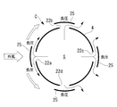
- FIG. 7 is a transverse sectional view taken along line VII-VII in FIG. 6,
- FIG. 8 is VIII in FIG. It is a cross-sectional view along line -VIII.
- the wind power generator 1C includes a cooling structure C.
- the introduction port 21 is disposed near the lower end portion of the tower 4, and the discharge ports 22 a to 22 d are disposed near the upper end of the tower 4.
- the introduction port 21 is provided only at one place on the surface of the outer peripheral surface of the tower 4 that is on average the best wind per year, that is, the position where the positive pressure due to the outside wind is highest throughout the year. ing.
- the discharge ports 22a to 22d are provided at a height near the upper end of the tower 4 at, for example, four positions at intervals of 90 ° in the circumferential direction. May be set arbitrarily.
- a saddle member 25 is provided as a negative pressure increasing means for increasing the negative pressure received by the external wind.
- the flange member 25 is a plate-like member that covers the openings of the discharge ports 22a to 22d and is fixed at a predetermined distance from the discharge ports 22a to 22d via stays or brackets (not shown).
- the area of the gutter member 25 is set to be slightly larger than the opening area of the discharge ports 22a to 22d.
- the eaves member 25 is curved along the curved shape of the outer peripheral surface of the tower 4, but may be flat, for example.
- the cooling structure C configured as described above operates as follows.
- the outside wind blows to the wind power generator 1C
- the outside wind blows as it is into the inlet 21 provided at the position where the positive pressure due to the outside wind becomes the highest, and is introduced into the interior of the tower 4 as cooling air, and the electric equipment After the heat generating equipment such as 14 is cooled, the process proceeds from the outlets 22a to 22d provided above.
- the discharge ports 22a to 22d the negative pressure of the outside wind acting on the discharge ports 22a to 22d is increased by providing the flange member 25.
- the position of the discharge port 22a directly facing the outside wind is the place where the highest positive pressure is received by the outside wind as in FIG.
- the provision of the eaves member 25 causes the outside wind to collide with the eaves member 25 without entering the inside of the discharge port 22a, and then to the left and right. And then flows backward along the outer peripheral curved surface of the tower 4 as it is. For this reason, a strong negative pressure is generated between the flange member 25 and the outer peripheral surface of the tower 4, that is, in the vicinity of the discharge port 22 a, thereby sucking the air inside the tower 4 from the discharge port 22 a to the outside.
- the positions where the discharge ports 22b and 22d are provided are perpendicular to the circumferential direction (90 °) from the position of the discharge port 22a that receives the highest positive pressure by the external wind. Since it is provided, it is a place where the negative pressure generated by the flow of the external wind is almost maximized. For this reason, even if there is no saddle member 25, a strong negative pressure acts on the discharge ports 22b and 22d, and an inside air suction action as shown in FIG. 3 is achieved. Further, by providing the flange member 25 here, the flow of the external wind flowing backward along the outer peripheral curved surface of the tower 4 is rectified, and the separation of the air flow in the vicinity of the discharge ports 22b and 22d is prevented. The negative pressure acting on the outlets 22b and 22d is increased.
- the cooling air in the internal space S is sucked out from the discharge ports 22b and 22d so as to be merged with the flow of the outside wind passing by the discharge ports 22b and 22d.
- the inside air is also discharged from the discharge port 22c.
- the discharge ports 22a to 22d are provided at four locations at equal intervals in the circumferential direction, but the present invention is not particularly limited only to the form. Even if the discharge ports 22b and 22d shown in FIG. 7 are provided at a position shifted by 120 ° in the circumferential direction from the position of the discharge port 22a, the discharge ports 22b and 22d are similarly provided by providing the flange member 25. A strong negative pressure can be applied to the surface.
- the flange member 25 at the discharge ports 22a to 22d, the negative pressure of the external wind acting on the discharge ports 22a to 22d can be increased, and the discharge port is located at a position facing the external wind. Since a large amount of inside air can be drawn out from the air inlet 22a, the pressure difference between the inlet 21 and the outlets 22a to 22d is increased, sufficient outside air is introduced from the inlet 21 and the interior space S Can be efficiently discharged from the discharge ports 22a to 22d, and the internal cooling performance of the wind turbine generator 1C can be improved.
- the eaves member 25 has a very simple configuration, there is no concern that the construction cost of the wind power generator 1C will be improved.
- the strength reduction of the tower 4 due to the perforations of the discharge ports 22a to 22d can be reduced.
- the upper and lower ends of the flange member 25 are bent or curved toward the outer peripheral surface of the tower 4, and the distal end portion is fixed to the outer peripheral surface of the tower 4, thereby It is conceivable to form a tunnel shape and to distribute the external air in the circumferential direction inside the tunnel-shaped flange member 25. Thereby, the installation location of the discharge port 22 can be increased without impairing the strength of the tower 4, or the opening area of the discharge port 22 can be increased to improve the cooling efficiency.
- FIG. 10 is a schematic longitudinal sectional view of a wind turbine generator 1D according to the fourth embodiment of the present invention.
- the wind power generator 1D includes a cooling structure D.
- this cooling structure D the difference from the cooling structure C in the third embodiment described above is that the installation location of the introduction port 21 is provided not on the tower 4 but on the front surface of the nacelle 5 and from the four discharge ports 22a. It is only that the installation height of 22d is near the lower end part of the tower 4, and the other structure is the same as that of the cooling structure C.
- the number of the discharge ports 22a to 22d is not necessarily four.
- the inlet 21 is open on the front surface of the nacelle 5 below, for example, a portion where the rotating shaft 12 of the wind turbine blade 9 protrudes, but opens toward the front (windward side). If it exists, you may provide in other places, for example, the side surface of the nacelle 5, an upper surface, etc.
- the circumferential position of the discharge ports 22a to 22d provided on the outer peripheral surface of the tower 4 and the structure, action, effect, etc. of the flange member 25 as the negative pressure increasing means are the same as those of the cooling structure C.
- the introduction port 21 provided in the nacelle 5 is always directed to the windward side in accordance with the control rotation of the nacelle 5, so that the external wind taken from the introduction port 21 is always taken. Maximum amount can be secured.
- the discharge ports 22a to 22d side by providing the flange member 25, the good exhaust action as described above is obtained, so that the pressure difference between the introduction port 21 and the discharge ports 22a to 22d is increased.
- the supply amount of the cooling air supplied to the internal space S of the wind power generator 1D can be increased, and high cooling efficiency can be obtained without power.
- the electric equipment 14 installed at the bottom of the tower 4 but also the heat generating equipment such as the generator 11 installed in the nacelle 5 can be reliably cooled.
- FIG. 11 is a schematic longitudinal sectional view of a wind turbine generator 1E according to a fifth embodiment of the present invention
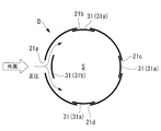
- FIG. 12 is a transverse sectional view taken along line XII-XII in FIG. 11
- FIG. 13 is XIII in FIG. It is a cross-sectional view along line -XIII.
- the wind power generator 1E includes a cooling structure E.
- this cooling structure E four inlets 21a to 21d are arranged in the vicinity of the lower end of the tower 4 at intervals of, for example, 90 ° in the circumferential direction, and four outlets 22a to 22d are also arranged in the circumferential direction near the upper end of the tower 4. They are arranged at 90 ° intervals.
- Each inlet 21a to 21d is provided with an inner lid member 31 as inlet opening / closing means
- each outlet 22a to 22d is provided with an outer lid member 32 as outlet opening / closing means.
- the number of the introduction ports 21a to 21d and the discharge ports 22a to 22d does not necessarily have to be four, and the number and interval may be arbitrarily set, for example, three at 120 ° intervals.
- the inner lid member 31 is a plate-like member that is curved along the inner peripheral surface of the tower 4 and is formed so that the inlets 21 a to 21 d can be airtightly closed from the inside.
- the inlets 21a to 21d are provided so as to be detachable from the inside.
- the outer lid member 32 is a plate-like member that is curved along the outer peripheral surface of the tower 4 and is formed so as to airtightly close the discharge ports 22a to 22d from the outside.
- the outlets 22a to 22d are provided so as to be separable from the outside.
- the inner lid member 31 has a rod-shaped guide rod 35 fixed vertically at the center thereof, and a stopper plate 36 is fixed to the other end of the guide rod 35.
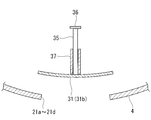
- a slide pipe 37 is fixed inside the introduction ports 21a to 21d by a stay member (not shown), and a guide rod 35 is inserted into and supported by the slide pipe 37 so as to be slidable in the axial direction. Therefore, the inner lid member 31 can move between the closed position 31a shown in FIG. 14A and the open position 31b shown in FIG. 14B.
- the inner lid member 31 closely contacts the inlets 21a to 21d from the inner side to close the inlets 21a to 21d, and the stopper plate 36 contacts the inner end of the slide pipe 37.
- the inner lid member 31 moves away from the introduction ports 21a to 21d to open the introduction ports 21a to 21d. At this time, the inner lid member 31 abuts against the outer end portion of the slide pipe 37 and the movement is restricted.
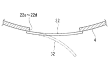
- the outer lid member 32 is a slide pipe 37 in which a guide rod 35 fixed to the center thereof is fixed inside the discharge ports 22a to 22d, as shown in FIGS. 15A and 15B.
- the stopper plate 36 is fixed to the other end portion of the guide rod 35.
- the outer side cover member 32 can move between the obstruction
- the outer lid member 32 closely contacts the discharge ports 22a to 22d from the outside to close the discharge ports 22a to 22d.
- the open position 32b the outer lid member 32 is spaced outward from the outlets 22a to 22d to open the outlets 22a to 22d.
- the stopper plate 36 abuts the inner end of the slide pipe 37 and the outer lid member 32 Movement is regulated.
- the inner lid member 31 slides from the closed position 31a to the open position 31b when the pressure outside the inlets 21a to 21d is higher than the inner pressure, and the pressure inside the inlets 21a to 21d is higher than the outer pressure. If the height also rises, it slides from the open position 31b to the closed position 31a.
- the outer lid member 32 slides from the open position 32b to the closed position 32a when the air pressure outside the discharge ports 22a to 22d becomes higher than the air pressure inside, and the air pressure inside the discharge ports 22a to 22d is higher than the air pressure outside. When the height also rises, it slides from the closed position 32a to the open position 32b.
- the sliding operation of the inner lid member 31 and the outer lid member 32 may be naturally moved by being pressed by the atmospheric pressure, but is controlled to open and close according to the atmospheric pressure by using a dedicated driving device and a control device. You may do it.
- the cooling structure E configured as described above operates as follows. For example, when the outside wind blows from the front to the wind power generator 1E, the outside air pressure of the introduction port 21a facing the outside wind among the four introduction ports 21a to 21d provided in the vicinity of the lower end of the tower 4 is outside. Since the pressure is higher than the inner pressure, the inner lid member 31 is pressed by the pressure and slides to the open position 31b, and the introduction port 21a is opened. On the other hand, since the introduction ports 21b and 21d are located at a position 90 ° away from the introduction port 21a in the circumferential direction, negative pressure acts on these positions as the outside wind flows on the surface. Further, a negative pressure acts on the outside of the introduction port 21c.
- the outer lid member 32a has an outer pressure higher than the inner pressure at the outlet 22a facing the outside wind. Is pressed by the atmospheric pressure and slides to the closing position 32a, and the discharge port 22a is closed. Since the discharge ports 22b and 22d are located at a position 90 ° away from the discharge port 22a in the circumferential direction, negative pressure acts on these positions as the outside wind flows on the surface. Negative pressure also acts outside the discharge port 22c.
- the air pressure inside thereof becomes higher than the air pressure outside, and the respective outer lid members 32 slide to the open position 32b, and the discharge ports 22b, 22c, and 22d are opened. The Therefore, the air inside the tower 4 is discharged from the discharge ports 22b, 22c, and 22d except for the discharge port 22a that faces the outside wind.
- the inner lid member 31 and the outer lid member 32 can be simply configured, the cost is not greatly increased.
- the inner lid member 31 and the outer lid member 32 are not limited to the slide type described above, and may have other structures.
- the inner lid member 31 and the outer lid member 32 are configured in a flapper type (reed valve type), whereby the structure can be further simplified.
- FIG. 17 is a schematic longitudinal sectional view of a wind turbine generator 1F according to the sixth embodiment of the present invention.
- the wind power generator 1F includes a cooling structure F.
- This cooling structure F is different from the cooling structure E in the fifth embodiment described above only in that the installation location of the discharge port 22e is provided on the rear surface of the nacelle 5 instead of the tower 4, and from the introduction port 21a.
- the structure of the other parts including 21d is the same as that of the cooling structure E.
- the outlet 22e When the outlet 22e is provided on the rear surface of the nacelle 5, the outlet 22e is always directed to the leeward side of the outside wind according to the rotation of the nacelle 5, and when the outlet 22f is provided on the side surface of the nacelle 5, Since the discharge port 22f is located at a place where a strong negative pressure is generated by the external wind, in any case, a strong negative pressure acts on the outside of the discharge ports 22e and 22f, and the air in the nacelle 5 and thus the internal space S of the tower 4 The effect
- the amount of cooling air supplied from the inlets 21a to 21d to the internal space S of the wind power generator 1F is increased, and the electric equipment 14 installed at the bottom of the tower 4 and the power generation installed in the nacelle 5 are installed.
- the heat generating equipment such as the machine 11 can be effectively cooled.
- FIG. 18 is a schematic longitudinal sectional view of a wind turbine generator 1G according to a seventh embodiment of the present invention
- FIG. 19 is a transverse sectional view taken along line XIX-XIX in FIG.
- This wind power generator 1G includes a cooling structure G.
- a cylindrical inner wall 41 is provided inside the tower 4 so that the tower 4 has a double-pipe structure
- an outer space S1 is defined on the outer peripheral side inside the tower 4, and the outer space S1.
- An inner space S ⁇ b> 2 is defined on the inner peripheral side.
- the introduction port 21 is provided so as to communicate with the outer space S1
- the discharge port 22 is provided so as to communicate with the inner space S2.
- the heights of the introduction port 21 and the discharge port 22 are both set in the vicinity of the intermediate portion of the tower 4, but the heights may be different.
- FIG. 19 shows the circumferential positions of the introduction port 21 and the discharge port 22 in plan view.
- the circumferential positions of the inlet port 21 and the outlet port 22 are the same as the cooling structure A in the first embodiment shown in FIG. That is, the introduction port 21 is provided at a position where the positive pressure due to the outside wind is highest, and the discharge port 22 is provided at a position perpendicular to the circumferential direction from the position of the introduction port 21.
- Two outlets 22 may be provided on both sides of the inlet 21.
- the introduction port 21 penetrates the outer wall of the tower 4 and communicates with the outer space S1, and the outside air introduced from the introduction port 21 flows into the outer space S1.
- the discharge port 22 communicates with the inner space S2 through the communication pipe 43, and the air in the inner space S2 is discharged from the discharge port 22 without entering the outer space S1.
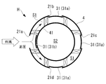
- the height of the upper end portion of the inner wall 41 is substantially the same as the height near the upper end of the tower 4, and the outer space S 1 and the inner space S 2 communicate with each other inside the nacelle 5. Since the height of the lower end portion of the inner wall 41 is slightly higher than the lower end portion of the tower 4, the outer space S ⁇ b> 1 and the inner space S ⁇ b> 2 communicate with each other in the vicinity of the lower end portion of the tower 4. Thus, the outer space S1 and the inner space S2 communicate with each other at a position away from the position where the introduction port 21 and the discharge port 22 are provided.
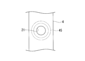
- an arc-shaped filter member 45 is provided around the introduction port 21.
- the filter member 45 is located on the downstream side of the introduction port 21 and functions as a foreign matter removing unit that removes foreign matters such as moisture, salt, and dust contained in the outside air introduced from the introduction port 21.
- the shape of the filter member 45 is not limited to an arc shape.
- the cross section of the filter member 45 shown in FIG. 18 is directly extended in the circumferential direction of the outer space S1 so as to have a large ring shape in plan view, and the introduction port 21 is sandwiched between the upper and lower filter members. May be.
- the cooling structure G configured as described above operates as follows.
- the external wind blows on the wind power generator 1G
- the external wind is first introduced into the outer space S1 as cooling air from the inlet 21 provided on the outer peripheral surface of the tower 4 that receives a positive pressure by the external wind.
- the outside wind flows in the vertical direction and the circumferential direction in the outer space S ⁇ b> 1 after removing foreign matters such as moisture, salt, and dust when passing through the filter member 45.
- the air that has flowed downward in the outer space S1 enters the inner space S2 while diverting the lower end of the inner wall 41 and changing the flow direction upward, and then cools the heat-generating electrical device 14 and moves upward. It flows and is discharged from the discharge port 22 to the outside. Since the discharge port 22 is provided in a place where the negative pressure generated by the external wind is substantially maximized, a large pressure difference is generated between the introduction port 21 and the discharge port 22, and air in the inner space S ⁇ b> 2 is eliminated. It can ventilate efficiently with power.
- the distance from the inlet 21 to the outlet 22 is increased, the direction of the airflow is changed between the outer space S1 and the inner space S2, and the outer space S1 that is a cylindrical space. Since centrifugal force acts on the airflow flowing in the circumferential direction in the interior, foreign substances such as moisture, salt, and dust contained in the external wind can be mainly spontaneously dropped in the outer space S1 and separated from the airflow, and the inlet 21 In combination with the provision of the filter member 45, it is possible to reliably prevent foreign matter from entering the inner space S2 and to effectively protect the internal devices.
- the filter member 45 may be simple and may not be provided in some cases, a sufficient amount of outside wind is introduced from the inlet 21 by avoiding or reducing pressure loss due to the filter member 45, and the wind turbine generator.
- the cooling efficiency inside 1G can be increased. Since the tower 4 has a double tube structure by providing the inner wall 41 inside the tower 4, the strength of the tower 4 can be increased.
- FIG. 21 is a schematic longitudinal sectional view of a wind turbine generator 1H according to an eighth embodiment of the present invention
- FIG. 22 is a transverse sectional view taken along line XXII-XXII in FIG. 21, and
- FIG. 23 is XXIII in FIG. It is a cross-sectional view along line -XXIII.
- the wind power generator 1H includes a cooling structure H.
- this cooling structure H similarly to the above-described cooling structure G, a cylindrical inner wall 41 is provided inside the tower 4 so that the tower 4 has a double-pipe structure. An inner space S2 is defined.
- four introduction ports 21 a to 21 d are arranged at intervals of 90 ° in the circumferential direction at a height slightly below the middle portion of the tower 4, and at a height slightly above the middle portion of the tower 4.
- the two outlets 22a to 22d are also arranged at 90 ° intervals in the circumferential direction.
- the inlets 21a to 21d penetrate the outer wall of the tower 4 and communicate with the outer space S1, and the outside air introduced from the inlets 21a to 21d flows into the outer space S1.
- the discharge ports 22a to 22d communicate with the inner space S2 through the communication pipe 43, and the air in the inner space S2 is discharged from the discharge ports 22a to 22d without entering the outer space S1.
- Each inlet 21a to 21d is provided with an inner lid member 31 as an inlet opening / closing means, and each of the outlets 22a to 22d is provided with an outer lid member 32 as an outlet opening / closing means.
- the configurations and actions of the inner lid member 31 and the outer lid member 32 are the same as those of the cooling structure E according to the fifth embodiment.
- Each inlet 21a to 21d is provided with a filter member 45 similar to the cooling structure G according to the seventh embodiment.
- the cooling structure H configured as described above operates as follows. For example, when outside wind is blown from the front to the wind power generator 1H, the outside wind out of the four inlets 21a to 21d provided on the outer peripheral surface of the tower 4 is the same as the cooling structure E in the fifth embodiment. Only the inner lid member 31 of the introduction port 21a that directly faces is opened (becomes an open position 31b), and the inner lid members 31 of the other three introduction ports 21b, 21c, and 21d are closed (becomes the closed position 31a). Therefore, the introduction ports 21b, 21c, and 21d are closed. For this reason, the outside wind flows into the outer space S1 only from the introduction port 21a.
- the inflowing outside air flows in the up and down direction and the circumferential direction in the outer space S ⁇ b> 1 after removing foreign matters such as moisture, salt and dust when passing through the filter member 45.
- the air that has flowed downward in the outer space S1 enters the inner space S2 while diverting the lower end portion of the inner wall 41 and changing the flow direction upward, and flows upward after cooling the heat-generating electrical device 14.
- the cooling structure E in 5th Embodiment among the four discharge ports 22a to 22d provided in the outer peripheral surface of the tower 4, only the outer side cover member 32 of the discharge port 22a which opposes an external wind is obstruct
- this cooling structure H as in the cooling structure G in the seventh embodiment, foreign substances such as moisture, salt, and dust contained in the external wind are mainly naturally dropped in the outer space S1 to be separated from the air flow, Equipment can be protected. Moreover, similarly to the cooling structure E, it is possible to reduce a problem that the cooling efficiency of the wind power generator 1E is lowered depending on the wind direction, and to obtain a stable cooling action throughout the year.
- FIG. 24 is a schematic longitudinal sectional view of a wind turbine generator 1J according to the ninth embodiment of the present invention
- FIG. 25 is a transverse sectional view taken along line XXV-XXV in FIG.
- the wind power generator 1J includes a cooling structure J.
- this cooling structure J for example, three vent holes 48a to 48c are formed at intervals of 120 ° in the vicinity of the lower end of the tower 4 along the circumferential direction of the outer peripheral surface of the tower 4, for example.
- These vents 48a to 48c serve as inlets for taking outside wind into the internal space S of the tower 4 or exhaust ports for exhausting air in the internal space S to the outside according to the wind direction.
- vent holes 48a to 48c are provided so as to surround the periphery of a heat generating device such as the electric device 14 installed in the lower part of the tower 4, but are not necessarily provided at the same height. You may give a height difference between 48a to 48c.
- the circumferential position and quantity of each vent 48a to 48c do not necessarily have to be three at 120 ° intervals, and may be three or more, for example.
- the cooling structure J configured as described above operates as follows. For example, when the outside wind blows on the wind power generator 1J, as shown in FIG. 25, if the outside wind is in the direction of the wind hitting the vent 48a, the vent 48a receives a positive pressure by the outside wind and becomes an introduction port. Is directly introduced into the interior of the tower 4 as cooling air from the vent 48a to cool the electric device 14. On the other hand, the vent holes 48b and 48c are exhausted because they receive negative pressure due to the outside wind, and the air in the internal space S is exhausted to the outside from here.
- vent 48b For example, if the direction of the wind from which the outside wind hits the vent 48b is changed, the vent 48b is now an inlet and the vents 48a and 48c are outlets. If the direction of the wind that the outside wind hits the vent 48c is changed, the vent 48c serves as an inlet and the vents 48a and 48b serve as outlets.
- one of the plurality of vent holes 48a to 48c serves as an introduction port and the other serves as a discharge port. Therefore, the electric device 14 is always excellent regardless of the wind direction. Can be cooled.
- the present invention is not limited to the aspects of the first to ninth embodiments described above.
Landscapes
- Engineering & Computer Science (AREA)
- Physics & Mathematics (AREA)
- Thermal Sciences (AREA)
- Life Sciences & Earth Sciences (AREA)
- Sustainable Development (AREA)
- Sustainable Energy (AREA)
- Chemical & Material Sciences (AREA)
- Combustion & Propulsion (AREA)
- Mechanical Engineering (AREA)
- General Engineering & Computer Science (AREA)
- Wind Motors (AREA)
Abstract
簡素かつ安価な構成により、電力消費を抑制しつつ、充分な外風を導入可能にして、ナセルやタワー内部に設置された発熱性のある電気機器を良好に冷却する。風車翼(9)に外風を受けて回転するロータヘッド(6)が、ナセル(5)の内部に設置された発電機(11)を駆動して発電し、ナセル(5)がタワー(4)の上端部に設置された風力発電装置(1A)であって、タワー(4)またはナセル(5)の外表面の、外風によって正圧を受ける部位に、この外風を風力発電装置(1A)の内部空間(S)に取り入れる導入口(21)を設け、タワー(4)またはナセル(5)の外周面の、外風によって負圧を受ける部位に、内部空間(S)の冷却空気を外部に排出する排出口(22)を設けたことを特徴とする。
Description
本発明は、運転時における機器の発熱を、外気の導入により冷却するようにした風力発電装置に関するものである。
標準的な風力発電装置は、風車翼を備えたロータヘッドが風力を受けて回転し、この回転を増速機により増速する等して発電機を駆動し、発電を行う装置である。ロータヘッドは、地面等に立設されたタワーの上に設置されてヨー旋回可能なナセルの端部に取り付けられ、略水平な横方向の回転軸線周りに回転可能となるように支持されている。
一般的に、上述したタワーとしては、円筒形状のタワーシェルを用いた鋼製モノポール式が採用される場合が多く、タワーシェルの下端部に設けられたベースプレートが鉄筋コンクリートの基礎にアンカーボルトで固定される構造となっている。このような風力発電装置の内部には発電機の他にも、コンバータや変圧器といった発熱性のある電気機器が設置されているため、安定した運転を継続するためには、これらの電気機器を適切に冷却する必要がある。
従来の単純な冷却構造としては、タワーまたはナセルの内部に換気ファンを設置し、外部の冷たい空気を内部に強制的に導入して発熱性のある電気機器の冷却を行うものがある。例えば、特許文献1に開示されているように、発熱性のある電気機器の内部に水やオイル等の冷却液を循環ポンプで循環させ、冷却に供された冷却液を熱交換器で熱交換させ、その排熱を外部に放散させる冷却構造が知られている。
しなしながら、上述のように、換気ファンを設置したり、冷却液を循環させたりすることによって発熱性のある電気機器を冷却する冷却構造とした場合には、その構成が複雑にならざるを得ない上に、換気ファンや循環ポンプを駆動するために、風力発電装置により発電した電力を消費しなければならず、芳しくない。
液冷式においては、そもそも構造が複雑であることに加え、熱交換器の設置によってナセル周りが大型化かつ高重量化するため、必然的にタワーの強度を高めなければならず、さらに、熱交換器が外気に晒される構造であるため、風力発電装置が沿岸部や海上に設置される場合には熱交換器の腐食対策を充分に行わなければならず、これらの要因によって風力発電装置の建造コストが高額になるという問題があった。
タワーに、外風を取り入れる導入口や、内部の空気を排気させる排出口を設ける場合には、これらの開口部の数や開口面積を必要最低限として、タワーの強度を確保しなければならない。
本発明は、上記の事情に鑑みてなされたものであり、簡素かつ安価な構成により、電力消費を抑制しつつ、充分な外風を導入可能にして、ナセルやタワーの内部に設置された発熱性のある電気機器を良好に冷却することのできる風力発電装置を提供することを目的とする。
本発明は、上記の課題を解決するため、下記の手段を採用した。
即ち、本発明の一態様に係る風力発電装置は、風車翼に外風を受けて回転するロータヘッドが、ナセルの内部に設置された発電機を駆動して発電し、前記ナセルがタワーの上端部に設置された風力発電装置において、前記タワーまたは前記ナセルの外表面の、外風によって正圧を受ける部位に、この外風を風力発電装置の内部空間に取り入れる導入口を設け、前記タワーまたは前記ナセルの外周面の、外風によって負圧を受ける部位に、前記内部空間の冷却空気を外部に排出する排出口を設けた。
即ち、本発明の一態様に係る風力発電装置は、風車翼に外風を受けて回転するロータヘッドが、ナセルの内部に設置された発電機を駆動して発電し、前記ナセルがタワーの上端部に設置された風力発電装置において、前記タワーまたは前記ナセルの外表面の、外風によって正圧を受ける部位に、この外風を風力発電装置の内部空間に取り入れる導入口を設け、前記タワーまたは前記ナセルの外周面の、外風によって負圧を受ける部位に、前記内部空間の冷却空気を外部に排出する排出口を設けた。
このような風力発電装置によれば、風力発電装置に外風が吹き付けた場合に、タワーまたはナセルの外周面に設けられて外風により正圧を受ける導入口と、同じく外風により負圧を受ける排出口との間に圧力差が生じるため、無動力で風力発電装置の内部を換気することができる。即ち、導入口から取り入れられる外風を冷却空気として風力発電装置の内部に流し、風力発電装置の内部に設置された発熱性のある電気機器を良好に冷却させた後、排出口から外部に排出することができる。
このように、導入口と排出口との間に生じる圧力差を利用して外風を風力発電装置の内部に取り入れ、内部に設置された発熱性のある電気機器を冷却することができ、外風を取り入れるために換気ファン等を設ける必要がないため、簡素かつ安価な構成により、電力を消費することなく、ナセルやタワー内部に設置された発熱性のある電気機器を良好に冷却することができる。
上記態様に係る風力発電装置は、前記導入口と前記排出口との間に、発熱機器が配置されることとしてもよい。これにより、発熱機器を良好に冷却することができる。
上記態様に係る風力発電装置は、前記導入口と前記排出口を前記タワーに設ける場合に、その外周面の周方向のうち、前記外風による正圧が最も高くなる位置に前記導入口を設け、この導入口の位置から周方向に略直角となる位置に前記排出口を設けることとしてもよい。
上記構成によれば、タワーの外周面において外風による正圧が最も高くなる位置に導入口が設けられ、この導入口の位置から周方向に略直角となる位置に設けられた排出口には、外風がタワー外周面に沿って流れる際に最も大きな負圧が作用するため、導入口に加わる正圧と排出口に加わる負圧との圧力差が最大になる。このため、導入口からは外風が効率良く風力発電装置の内部に取り込まれ、排出口からは風力発電装置の内部を冷却した内気が効率良く外部に排出されて、冷却効率が高まる。
上記態様に係る風力発電装置は、前記導入口の位置と前記排出口の位置との間に高低差を設けることとしてもよい。これにより、風力発電装置の内部空間を広く冷却するとともに、導入口と排出口とが近接して配置されることによるタワー強度の低下を回避することができる。
上記態様に係る風力発電装置は、前記導入口を前記タワーに設ける場合に、その高さを、前記タワーが立設される地表面から前記風車翼先端の回転軌跡の下端までの範囲のうちの最も高い位置付近に設定することとしてもよい。
一般に、タワーが立設される地表面の近くでは、外風の対地速度が低く、風車翼の後部では風車翼の回転による気流の乱れが生じるため、前記のように導入口を地表面から風車翼先端の回転軌跡の下端までの範囲のうちの最も高い位置付近に設定することにより、対地速度の速い外風を、気流の乱れに影響されることなく導入口から導入することができ、風力発電装置の内部を良好に冷却することができる。
上記態様に係る風力発電装置は、前記排出口に、前記外風によって受ける負圧を増長させる負圧増長手段を設けることとしてもよい。これにより、排出口に作用する負圧が増長されるため、風力発電装置内部の空気を効率良く排出口から排出させて、風力発電装置内部の冷却効率を高めることができる。
上記態様に係る風力発電装置は、前記負圧増長手段が、前記排出口の開口部を覆い、且つ前記排出口に対して所定の距離だけ離間した暈部材であることとしてもよい。本構成によれば、負圧増長手段を非常に簡素に構成することができる。
上記態様に係る風力発電装置は、前記導入口に、その外側の気圧が内側の気圧よりも高まった場合に開き、内側の気圧が外側の気圧よりも高まった場合に閉じる導入口開閉手段を設けることとしてもよい。
上記構成によれば、例えば円断面形状を有するタワーの周方向に沿って複数の導入口を設けた場合に、外風に正対している導入口では、その外側の気圧が内側の気圧よりも高まるために導入口開閉手段が開き、他の導入口では、その外側の気圧が内側の気圧よりも低くなるために導入口開閉手段が閉じる。このため、外風が効率良く導入されるとともに、一旦導入された外風が他の導入口から逃げてしまうことが防止される。したがって、導入口と排出口との間における圧力差を大きくし、充分な量の外風を風力発電装置の内部に送り込んで風力発電装置内部の冷却効率を高めることができる。
上記態様に係る風力発電装置は、前記排出口に、その外側の気圧が内側の気圧よりも高まった場合に閉じ、内側の気圧が外側の気圧よりも高まった場合に開く排出口開閉手段を設けることとしてもよい。
上記構成によれば、例えば円断面形状を有するタワーの周方向に沿って複数の排出口を設けた場合に、外風に正対している排出口では、その外側の気圧が内側の気圧よりも高まるために排出口開閉手段が閉じ、他の排出口では、その外側の気圧が内側の気圧よりも低くなるために排出口開閉手段が開く。このため、内気が効率良く排出され、相対的に多くの外風を導入口から取り入れて、風力発電装置内部の冷却効率を高めることができる。
上記態様に係る風力発電装置は、前記タワーを二重管構造とし、その外側空間または内側空間のどちらか一方の空間に連通するように前記導入口を設け、他方の空間に連通するように前記排出口を設け、前記外側空間と前記内側空間とを、前記導入口および前記排出口から離れた位置で連通させることとしてもよい。
本構成によれば、導入口から排出口までの距離が長くなることと、外側空間と内側空間との間で気流の方向が変わることと、円筒形の空間となる外側空間内を周方向に流れる気流に遠心力が働くことから、外風に含まれる水分、塩分、塵埃といった異物を主に外側空間内で自然落下させて気流から分離させることができ、導入口にフィルタ等の圧損部材を設けなくてもよいか、あるいは設けたとしても簡易的なものでよくなるため、導入口から充分な量の外風を取り入れて風力発電装置内部の冷却効率を高めることができる。
上記態様に係る風力発電装置は、前記導入口の下流側に、前記導入口から導入される外気に含まれる異物を除去する異物除去手段を設けることとしてもよい。こうすれば、外風に含まれる水分、塩分、塵埃等の異物を除去して内部機器の健全性を保つことができる。
上記態様に係る風力発電装置は、前記導入口と前記排出口を前記タワーに設ける場合に、その外周面の周方向に沿って3箇所以上の通気口を設け、これらの通気口が、風向きに応じて前記導入口または前記排出口になるようにすることとしてもよい。このようにした場合、外風の風向きに拘わらず、常に良好にタワー内部を冷却することができる。
以上のように、本発明に係る風力発電装置によれば、導入口と排出口との間に生じる圧力差を利用して、簡素かつ安価な構成により、電力消費を抑制しつつ、充分な外風を導入可能にして、ナセルやタワー内部に設置された発熱性のある電気機器を良好に冷却することができる。
以下、本発明に係る風力発電装置の実施形態について、図面に基づいて説明する。
図1は、後に説明する各実施形態における冷却構造AからHを適用可能な風力発電装置の一例を示す側面図である。この風力発電装置1は、地表面2に設置された鉄筋コンクリート製の基礎3上に立設されるタワー4と、このタワー4の上端部に設置されるナセル5と、略水平な横方向の回転軸線周りに回転可能に支持されてナセル5の前端部側に設けられるロータヘッド6とを有している。
図1は、後に説明する各実施形態における冷却構造AからHを適用可能な風力発電装置の一例を示す側面図である。この風力発電装置1は、地表面2に設置された鉄筋コンクリート製の基礎3上に立設されるタワー4と、このタワー4の上端部に設置されるナセル5と、略水平な横方向の回転軸線周りに回転可能に支持されてナセル5の前端部側に設けられるロータヘッド6とを有している。
タワー4は、鋼管製のモノポール式であり、その横断面形状が略円形である。タワー4の下端部には例えば鋼板製のベースプレート7が固定され、このベースプレート7が多数のアンカーボルト8で基礎3に締結固定されている。ロータヘッド6には、放射方向に延びる複数枚(例えば3枚)の風車翼9が取り付けられており、ナセル5の内部には発電機11が収容設置され、ロータヘッド6の回転軸12が発電機11の主軸に増速機等を介して連結されている。このため、風車翼9に当たった外風の風力が、ロータヘッド6と回転軸12を回転させる回転力に変換され、発電機11が駆動されて発電が行われる。
ナセル5は、風車翼9と共に、タワー4の上端において水平方向に旋回することができ、図示しない駆動装置と制御装置により、常に風上方向に指向して効率良く発電できるように制御される。また、タワー4の内部空間S内には、外部の風雨に晒すことができない電気機器14が設置されている。この電気機器14として、コンバータや変圧器といった発熱性のあるものが例示されるが、タワー4の内部空間Sは密室状であるため、以下に述べる各実施形態における冷却構造AからJによって内部空間Sに設置された電気機器14の熱を冷却するようになっている。
(第1実施形態)
図2は、本発明の第1実施形態に係る風力発電装置1Aの概略的な縦断面図であり、図3は図2のIII-III線に沿う横断面図である。この風力発電装置1Aは冷却構造Aを備えている。この冷却構造Aでは、前述したように略円形の横断面形状を有するタワー4に、導入口21と排出口22とが設けられている。導入口21は、外風を冷却空気としてタワー4の内部空間Sに取り入れる開口部であり、タワー4の外表面の、外風によって正圧を受ける部位に設けられている。排出口22は、内部空間S内の冷却空気を外部に排気する開口部であり、タワー4の外表面の、外風によって負圧を受ける部位に設けられている。
図2は、本発明の第1実施形態に係る風力発電装置1Aの概略的な縦断面図であり、図3は図2のIII-III線に沿う横断面図である。この風力発電装置1Aは冷却構造Aを備えている。この冷却構造Aでは、前述したように略円形の横断面形状を有するタワー4に、導入口21と排出口22とが設けられている。導入口21は、外風を冷却空気としてタワー4の内部空間Sに取り入れる開口部であり、タワー4の外表面の、外風によって正圧を受ける部位に設けられている。排出口22は、内部空間S内の冷却空気を外部に排気する開口部であり、タワー4の外表面の、外風によって負圧を受ける部位に設けられている。
より具体的には、風力発電装置1Aの設置場所を地理的に考察して、タワー4の外周面の周方向のうち、年間を通して平均的に最も風当たりの良い面、即ち外風による正圧が最も高くなる位置に導入口21が設けられ、この導入口21の位置から周方向に直角となる位置に排出口22が設けられている。図3では導入口21から片方に90°離れた位置に1箇所の排出口22が設けられているが、タワー4の強度や諸々の条件が許せば、導入口21の両側に2箇所の排出口22を設けてもよい。
導入口21および排出口22の形状は、できるだけタワー4の強度に支障を来さない形状であることが望ましい。例えば、応力が集中しにくい円形、縦長の楕円形、長円形等である。本実施形態および後に述べる各実施形態においても、導入口21および排出口22をそれぞれ単一の開口部とせずに、複数の小孔やスリット等を近接させて形成することにより構成してもよい。これにより、導入口21および排出口22の形成に伴うタワー4の強度低下を最小限に抑えることができる。
導入口21の位置と排出口22の位置との間には高低差が設けられている。例えば導入口21はタワー4の下端部付近、つまり地表面2と電気機器14に近い位置に形成されており、排出口22は、タワー4の上端付近に形成されている。これにより、タワー4の内部空間Sを広く冷却するとともに、導入口21と排出口22とが近接して配置されることによるタワー4の強度低下を回避することができる。電気機器14は導入口21と排出口22との間に配置されている。
以上のように構成された冷却構造Aは、次のように作用する。
風力発電装置1Aに外風が吹き付けた場合、タワー4の外周面の、外風によって正圧を受ける部位に設けられた導入口21と、同じく外風により負圧を受ける排出口22との間に圧力差が生じ、無動力で自然に風力発電装置1Aの内部が換気される。即ち、導入口21から外風が冷却空気としてタワー4の内部に直接導入され、この冷却空気は、タワー4の内部空間S内に設置された発熱性のある電気機器14を冷却するのと引き換えに温度が上昇し、熱気が上方に対流する自然法則に則って上方に形成された排出口22の方に流れる。
風力発電装置1Aに外風が吹き付けた場合、タワー4の外周面の、外風によって正圧を受ける部位に設けられた導入口21と、同じく外風により負圧を受ける排出口22との間に圧力差が生じ、無動力で自然に風力発電装置1Aの内部が換気される。即ち、導入口21から外風が冷却空気としてタワー4の内部に直接導入され、この冷却空気は、タワー4の内部空間S内に設置された発熱性のある電気機器14を冷却するのと引き換えに温度が上昇し、熱気が上方に対流する自然法則に則って上方に形成された排出口22の方に流れる。
一方、排出口22は、前述の通り、外風によって最も高い正圧を受ける導入口21の位置から周方向に直角となる位置に設けられているが、この位置は、外風によって発生する負圧がほぼ最大となる場所である。図4に、円筒外周における圧力分布の公知データを示すように、導入口21の周方向位置を0°とした場合、この0°の位置に作用する正圧が最大値の+1であるとするならば、ここから周方向に30°、60°と移動するにしたがって正圧が負圧に変化し、ほぼ90°近辺の位置で負圧が最大値の-1以下となる。つまり絶対値では負圧の方が正圧よりも大きくなる。
したがって、この90°の位置に設けられた排出口22に大きな負圧が作用し、図3に示すように排出口22の傍を通る外風の流れに合流するように、内部空間S内の冷却空気が排出口22から外部に強力に吸い出されて効率良く排出される。そして、導入口21と排出口22との間に配置された電気機器14が冷却空気によって効果的に冷却される。
以上のように、冷却構造Aを備えた風力発電装置1Aによれば、非常に簡素かつ安価な構成により、外風を導入口21から風力発電装置1A(タワー4)の内部空間S内に取り入れて発熱性のある電気機器14を冷却させた後、その熱気を排出口22からスムーズに排出させることができる。特に、タワー4の外周面の、外風によって正圧を受ける部位に導入口21を設け、この導入口21から周方向に略直角となる位置に排出口22を設けたため、導入口21に作用する正圧と排出口22に作用する負圧との圧力差を最大に確保し、換気ファン等の動力を用いずに効率良く外風を導入口21から取り入れて排出口22から排出できるため、電力を消費することなく電気機器14等を良好に冷却することができる。
(第2実施形態)
図5は、本発明の第2実施形態に係る風力発電装置1Bの概略的な縦断面図である。この風力発電装置1Bは冷却構造Bを備えている。この冷却構造Bにおいて、前述の第1実施形態における冷却構造Aと異なる点は、導入口21の設置高さがタワー4の中間部付近であることと、排出口22の設置高さがタワー4の下端部付近であることのみであり、他の構成は冷却構造Aと同様である。即ち、平面視における導入口21と排出口22の位置関係は図3に示す通りであり、それによってもたらされる作用効果も冷却構造Aと同様である。
図5は、本発明の第2実施形態に係る風力発電装置1Bの概略的な縦断面図である。この風力発電装置1Bは冷却構造Bを備えている。この冷却構造Bにおいて、前述の第1実施形態における冷却構造Aと異なる点は、導入口21の設置高さがタワー4の中間部付近であることと、排出口22の設置高さがタワー4の下端部付近であることのみであり、他の構成は冷却構造Aと同様である。即ち、平面視における導入口21と排出口22の位置関係は図3に示す通りであり、それによってもたらされる作用効果も冷却構造Aと同様である。
この冷却構造Bでは、導入口21の高さが、地表面2から風車翼9の先端9aの回転軌跡下端までの範囲Rのうちの最も高い位置付近に設定されている。図5中に外風の速度分布を示すように、一般に外風の対地速度は地表面2の近くでは低く、地表面2から離れるにしたがって速くなる傾向がある。風車翼9の後部では、風車翼9の回転に伴う気流の乱れが生じるため、風車翼9の回転軌跡の後部に重ならない上記の高さ位置に導入口21を設けることにより、比較的対地速度の速い外風を、風車翼9による気流の乱れに影響されることなく導入口21から導入することができ、風力発電装置1Bの内部を良好に冷却することができる。
排出口22の高さは、必ずしもタワー4の下端部付近でなくてもよいが、発熱性のある電気機器14が導入口21と排出口22の間に配置されていることが望ましいため、ここでは排出口22を電気機器14の設置位置に合わせてタワー4の下端部付近に配置した。
(第3実施形態)
図6は、本発明の第3実施形態に係る風力発電装置1Cの概略的な縦断面図であり、図7は図6のVII-VII線に沿う横断面図、図8は図6のVIII-VIII線に沿う横断面図である。この風力発電装置1Cは冷却構造Cを備えている。この冷却構造Cでは、第1実施形態における冷却構造Aと同じく、タワー4の下端部付近に導入口21が配置され、タワー4の上端付近に排出口22aから22dが配置されている。
図6は、本発明の第3実施形態に係る風力発電装置1Cの概略的な縦断面図であり、図7は図6のVII-VII線に沿う横断面図、図8は図6のVIII-VIII線に沿う横断面図である。この風力発電装置1Cは冷却構造Cを備えている。この冷却構造Cでは、第1実施形態における冷却構造Aと同じく、タワー4の下端部付近に導入口21が配置され、タワー4の上端付近に排出口22aから22dが配置されている。
導入口21は、冷却構造Aと同じく、タワー4の外周面の周方向のうち、年間を通して平均的に最も風当たりの良い面、即ち外風による正圧が最も高くなる位置に1箇所だけ設けられている。一方、排出口22a~22dは、タワー4の上端部付近の高さに、例えば周方向に90°間隔で4箇所設けられているが、例えば120°間隔で3箇所に設ける等、数や間隔は任意に設定してよい。
各排出口22aから22dには、外風によって受ける負圧を増長させる負圧増長手段として、例えば暈部材25が設けられている。この暈部材25は、排出口22aから22dの開口部を覆い、且つ図示しないステーやブラケット類を介して排出口22aから22dに対し所定の距離だけ離間して固定された板状の部材である。暈部材25の面積は、排出口22aから22dの開口面積よりも一回り大きく設定されている。図7に示すように、暈部材25は、タワー4の外周面の湾曲形状に沿って湾曲しているが、例えば平板状であってもよい。
以上のように構成された冷却構造Cは、次のように作用する。
風力発電装置1Cに外風が吹き付けた場合、外風による正圧が最も高くなる位置に設けられた導入口21には外風がそのまま吹き込み、タワー4の内部に冷却空気として導入され、電気機器14等の発熱機材を冷却した後、上方に設けられた排出口22aから22dの方に進む。一方、排出口22aから22dにおいては、暈部材25が設けられたことにより、排出口22aから22dに作用する外風の負圧が増長される。
風力発電装置1Cに外風が吹き付けた場合、外風による正圧が最も高くなる位置に設けられた導入口21には外風がそのまま吹き込み、タワー4の内部に冷却空気として導入され、電気機器14等の発熱機材を冷却した後、上方に設けられた排出口22aから22dの方に進む。一方、排出口22aから22dにおいては、暈部材25が設けられたことにより、排出口22aから22dに作用する外風の負圧が増長される。
つまり、図7に示すように、外風に正対する排出口22aの位置は、図3と同様に外風によって最も高い正圧を受ける場所であるため、暈部材25が設けられていなければ外風がそのまま排出口22aの内部に進入してしまうが、暈部材25が設けられていることにより、外風が排出口22aの内部に進入せずに暈部材25に衝突し、その後左右に分流して、そのままタワー4の外周湾曲面に沿って後方に流れる。このため、暈部材25とタワー4の外周面との間、即ち排出口22aの付近に強い負圧が発生し、これによってタワー4の内部の空気が排出口22aから外部に吸い出される。
排出口22b,22dの設けられている位置は、前述の冷却構造Aの場合と同じく、外風によって最も高い正圧を受ける排出口22aの位置から周方向に直角(90°)となる位置に設けられているため、外風の流れによって発生する負圧がほぼ最大となる場所である。このため、暈部材25が無かったとしても排出口22b,22dには強い負圧が作用し、図3に示したような内気の吸引作用が奏される。さらに、ここに暈部材25を設けたことにより、タワー4の外周湾曲面に沿って後方に流れる外風の流れが整流され、排出口22b,22d付近における気流の剥離が防止されるため、排出口22b,22dに作用する負圧が増長される。
このため、図7に示すように、排出口22b,22dの傍を通る外風の流れに合流するように、内部空間S内の冷却空気が排出口22b,22dから外部に吸い出されて効率良く排出される。排出口22cの位置でも、暈部材25を設けたことにより負圧が増長されるため、排出口22cからも内気が排出される。ここでは排出口22aから22dが周方向等間隔に4箇所設けられた例で説明したが、本発明は特にその形態のみに限定されない。仮に、図7に示す排出口22b,22dが排出口22aの位置から周方向に120°ずれた位置に設けられていたとしても、暈部材25を設けることにより、同様にして排出口22b,22dに強い負圧を作用させることができる。
このように、排出口22aから22dに暈部材25を設けたことにより、排出口22aから22dに作用する外風の負圧を増長させることができ、しかも外風に正対する位置にある排出口22aからも多くの内気を引き出すことができるため、導入口21と排出口22aから22dとの間の圧力差をより大きくし、導入口21から充分な外風を導入するとともに、内部空間S内の空気を効率良く排出口22aから22dから排出して、風力発電装置1Cの内部冷却性を高めることができる。
しかも、外風の風向きが変わっても、複数設けられた排出口22aから22dには常に暈部材25による負圧増長作用が付与されるため、風向きによって風力発電装置1Cの冷却効率が低下する懸念が少なく、年間を通じて安定した冷却作用を得ることができる。暈部材25は非常に簡素な構成であるため、風力発電装置1Cの建造コストが向上する心配はない。
暈部材25を排出口22aから22dに対して頑強に固定し、この暈部材25を補強部材として活用することにより、排出口22aから22dを穿設したことによるタワー4の強度低下を軽減することが考えられる。例えば、図9に示すように、暈部材25の上下の端部をタワー4の外周面に向けて屈曲または湾曲させ、その先端部をタワー4の外周面に固着することにより、暈部材25をトンネル状に形成し、このトンネル状の暈部材25の内部に外風を周方向に流通させることが考えられる。これにより、タワー4の強度を損なわずに排出口22の設置個所を増やしたり、排出口22の開口面積を大きくしたりして、冷却効率を向上させることができる。
(第4実施形態)
図10は、本発明の第4実施形態に係る風力発電装置1Dの概略的な縦断面図である。この風力発電装置1Dは冷却構造Dを備えている。この冷却構造Dにおいて、先述の第3実施形態における冷却構造Cと異なる点は、導入口21の設置場所がタワー4ではなくナセル5の前面に設けられていることと、4つの排出口22aから22dの設置高さがタワー4の下端部付近であることのみであり、他の構成は冷却構造Cと同様である。排出口22aから22dの数は必ずしも4箇所でなくてもよい。
図10は、本発明の第4実施形態に係る風力発電装置1Dの概略的な縦断面図である。この風力発電装置1Dは冷却構造Dを備えている。この冷却構造Dにおいて、先述の第3実施形態における冷却構造Cと異なる点は、導入口21の設置場所がタワー4ではなくナセル5の前面に設けられていることと、4つの排出口22aから22dの設置高さがタワー4の下端部付近であることのみであり、他の構成は冷却構造Cと同様である。排出口22aから22dの数は必ずしも4箇所でなくてもよい。
この冷却構造Dにおいて、導入口21は、ナセル5の前面において、例えば風車翼9の回転軸12が突出している部分の下方に開口しているが、前方(風上側)に向かって開く構造であれば、他の場所、例えばナセル5の側面や上面等に設けてもよい。、タワー4の外周面に設けられた排出口22aから22dの周方向位置、および負圧増長手段としての暈部材25の構造、作用、効果等は、冷却構造Cと同様である。
このように構成された冷却構造Dによれば、ナセル5に設けられた導入口21が、ナセル5の制御回動に応じて常に風上側に向くため、導入口21から取り入れられる外風を常に最大量確保することができる。一方、排出口22aから22d側においては、暈部材25を設けたことによって先述した通りの良好な排気作用が得られるため、導入口21と排出口22aから22dとの間における圧力差をより大きくし、風力発電装置1Dの内部空間Sに供給される冷却空気の供給量を増量させて、無動力で高い冷却効率を得ることができる。しかも、タワー4の底部に設置された電気機器14のみならず、ナセル5内に設置された発電機11等の発熱機材も確実に冷却することができる。
(第5実施形態)
図11は、本発明の第5実施形態に係る風力発電装置1Eの概略的な縦断面図であり、図12は図11のXII-XII線に沿う横断面図、図13は図11のXIII-XIII線に沿う横断面図である。この風力発電装置1Eは冷却構造Eを備えている。この冷却構造Eでは、タワー4の下端部付近に4つの導入口21aから21dが例えば周方向に90°間隔で配置され、タワー4の上端付近に4つの排出口22aから22dが同じく周方向に90°間隔で配置されている。各導入口21aから21dに、導入口開閉手段としての内側蓋部材31が設けられ、各排出口22aから22dに、排出口開閉手段としての外側蓋部材32が設けられている。導入口21aから21dおよび排出口22aから22dの数は必ずしも4箇所でなくてもよく、例えば120°間隔で3箇所に設ける等、数や間隔は任意に設定してよい。
図11は、本発明の第5実施形態に係る風力発電装置1Eの概略的な縦断面図であり、図12は図11のXII-XII線に沿う横断面図、図13は図11のXIII-XIII線に沿う横断面図である。この風力発電装置1Eは冷却構造Eを備えている。この冷却構造Eでは、タワー4の下端部付近に4つの導入口21aから21dが例えば周方向に90°間隔で配置され、タワー4の上端付近に4つの排出口22aから22dが同じく周方向に90°間隔で配置されている。各導入口21aから21dに、導入口開閉手段としての内側蓋部材31が設けられ、各排出口22aから22dに、排出口開閉手段としての外側蓋部材32が設けられている。導入口21aから21dおよび排出口22aから22dの数は必ずしも4箇所でなくてもよく、例えば120°間隔で3箇所に設ける等、数や間隔は任意に設定してよい。
図13に示すように、内側蓋部材31は、タワー4の内周面に沿って湾曲し、導入口21aから21dを内側から気密的に閉塞できるように形成された板状の部材であり、導入口21aから21dに対して内側から離接可能に設けられている。図12に示すように、外側蓋部材32は、タワー4の外周面に沿って湾曲し、排出口22aから22dを外側から気密的に閉塞できるように形成された板状の部材であり、排出口22aから22dに対して外側から離接可能に設けられている。
内側蓋部材31は、例えば図14A,図14Bに示すように、その中心部に棒状のガイドロッド35が垂直に固定され、このガイドロッド35の他端部にストッパプレート36が固着されている。一方、図示しないステー部材によって導入口21aから21dの内部にスライドパイプ37が固定され、このスライドパイプ37にガイドロッド35が軸方向に摺動自在に挿入支持されている。このため、内側蓋部材31は、図14Aに示す閉塞位置31aと、図14Bに示す開放位置31bとの間を移動することができる。閉塞位置31aでは内側蓋部材31が導入口21aから21dに内側から密に当接して導入口21aから21dを閉塞するとともに、ストッパプレート36がスライドパイプ37の内側端部に当接する。開放位置31bでは内側蓋部材31が導入口21aから21dから内側に離れて導入口21aから21dを開口させ、この時には内側蓋部材31がスライドパイプ37の外側端部に当接して動きを規制される。
外側蓋部材32は、内側蓋部材31と同様に、図15A,図15Bに示すように、その中心部に固定されたガイドロッド35が、排出口22aから22dの内部に固定されたスライドパイプ37に摺動自在に支持され、ガイドロッド35の他端部にストッパプレート36が固着されている。このため、外側蓋部材32は、図15Aに示す閉塞位置32aと、図15Bに示す開放位置32bとの間を移動することができる。閉塞位置32aでは外側蓋部材32が排出口22aから22dに外側から密に当接して排出口22aから22dを閉塞する。開放位置32bでは外側蓋部材32が排出口22aから22dから外側に離れて排出口22aから22dを開口させ、この時にはストッパプレート36がスライドパイプ37の内側端部に当接して外側蓋部材32の動きが規制される。
内側蓋部材31は、導入口21aから21dの外側の気圧が内側の気圧よりも高まった場合に閉塞位置31aから開放位置31bにスライドし、導入口21aから21dの内側の気圧が外側の気圧よりも高まった場合に開放位置31bから閉塞位置31aにスライドする。外側蓋部材32は、排出口22aから22dの外側の気圧が内側の気圧よりも高まった場合に開放位置32bから閉塞位置32aにスライドし、排出口22aから22dの内側の気圧が外側の気圧よりも高まった場合に閉塞位置32aから開放位置32bにスライドする。このような内側蓋部材31と外側蓋部材32のスライド動作は、気圧に押されて自然に動くようにしてもよいが、専用の駆動装置と制御装置を用いて、気圧に応じて開閉制御するようにしてもよい。
以上のように構成された冷却構造Eは、次のように作用する。
例えば風力発電装置1Eに正面から外風が吹き付けた場合、タワー4の下端部付近に設けられた4つの導入口21aから21dのうち、外風に正対する導入口21aでは、その外側の気圧が内側の気圧よりも高くなるため、内側蓋部材31が気圧に押圧されて開放位置31bにスライドし、導入口21aが開放される。一方、導入口21b,21dは、導入口21aに対して周方向に90°離れた位置にあるため、この位置には外風が表面を流れることによって負圧が作用する。さらに、導入口21cの外部にも負圧が作用する。このため、導入口21b,21c,21dでは、その内側の気圧が外側の気圧よりも高くなり、各々の内側蓋部材31が閉塞位置31aにスライドして導入口21b,21c,21dが閉塞される。したがって、外風に正対している導入口21aからのみ外風がタワー4の内部空間Sに流入する。
例えば風力発電装置1Eに正面から外風が吹き付けた場合、タワー4の下端部付近に設けられた4つの導入口21aから21dのうち、外風に正対する導入口21aでは、その外側の気圧が内側の気圧よりも高くなるため、内側蓋部材31が気圧に押圧されて開放位置31bにスライドし、導入口21aが開放される。一方、導入口21b,21dは、導入口21aに対して周方向に90°離れた位置にあるため、この位置には外風が表面を流れることによって負圧が作用する。さらに、導入口21cの外部にも負圧が作用する。このため、導入口21b,21c,21dでは、その内側の気圧が外側の気圧よりも高くなり、各々の内側蓋部材31が閉塞位置31aにスライドして導入口21b,21c,21dが閉塞される。したがって、外風に正対している導入口21aからのみ外風がタワー4の内部空間Sに流入する。
他方、タワー4の上端部付近に設けられた4つの排出口22aから22dのうち、外風に正対する排出口22aでは、その外側の気圧が内側の気圧よりも高くなるため、外側蓋部材32が気圧に押圧されて閉塞位置32aにスライドし、排出口22aが閉塞される。排出口22b,22dは、排出口22aに対して周方向に90°離れた位置にあるため、この位置には外風が表面を流れることによって負圧が作用する。排出口22cの外部にも負圧が作用する。このため、排出口22b,22c,22dにおいては、その内側の気圧が外側の気圧よりも高くなり、各々の外側蓋部材32が開放位置32bにスライドして排出口22b,22c,22dが開放される。したがって、外風に正対している排出口22aを除く、排出口22b,22c,22dからタワー4内部の空気が排出される。
このようにして、風力発電装置1Eの内部空間Sに多くの外気を冷却空気として流通させることができるため、効率良く冷却することができる。しかも、外風の風向きが変わっても、複数設けられた導入口21aから21dと排出口22aから22dのうち、風向きに対して最適な位置のものだけが開口して外風を風力発電装置1Eの内部に取り入れたり、内気を外部に排出したりするため、風向きによって風力発電装置1Eの冷却効率が低下する懸念が少なく、年間を通じて安定した冷却作用を得ることができる。
内側蓋部材31および外側蓋部材32は簡素に構成できるため、多大なコストアップにはならない。内側蓋部材31および外側蓋部材32は上述したスライド式のものに限らず、他の構造にしてもよい。例えば図16A,図16Bに示すように、内側蓋部材31および外側蓋部材32をフラッパー型(リード弁型)に構成することにより、その構造を一層簡素にすることができる。
(第6実施形態)
図17は、本発明の第6実施形態に係る風力発電装置1Fの概略的な縦断面図である。この風力発電装置1Fは冷却構造Fを備えている。この冷却構造Fにおいて、先述の第5実施形態における冷却構造Eと異なるのは、排出口22eの設置場所がタワー4ではなくナセル5の後面に設けられていることのみであり、導入口21aから21dを始めとする他の部分の構成は冷却構造Eと同様である。なお、二点鎖線で示すようにナセル5の側面に排出口22fを設けてもよい。
図17は、本発明の第6実施形態に係る風力発電装置1Fの概略的な縦断面図である。この風力発電装置1Fは冷却構造Fを備えている。この冷却構造Fにおいて、先述の第5実施形態における冷却構造Eと異なるのは、排出口22eの設置場所がタワー4ではなくナセル5の後面に設けられていることのみであり、導入口21aから21dを始めとする他の部分の構成は冷却構造Eと同様である。なお、二点鎖線で示すようにナセル5の側面に排出口22fを設けてもよい。
ナセル5の後面に排出口22eを設けた場合は、排出口22eがナセル5の回動に応じて常に外風の風下側に向き、またナセル5の側面に排出口22fを設けた場合は、排出口22fが外風により強い負圧が生じる場所に位置するため、何れにしても排出口22e,22fの外部に強い負圧が作用し、ナセル5内の空気、ひいてはタワー4の内部空間S内の空気を排出口22e,22fから外部に吸引させる作用が奏される。したがって、導入口21aから21dから風力発電装置1Fの内部空間Sに供給される冷却空気の供給量を多くして、タワー4の底部に設置された電気機器14およびナセル5内に設置された発電機11等の発熱機材を効果的に冷却することができる。
(第7実施形態)
図18は、本発明の第7実施形態に係る風力発電装置1Gの概略的な縦断面図であり、図19は図18のXIX-XIX線に沿う横断面図である。この風力発電装置1Gは冷却構造Gを備えている。この冷却構造Gでは、タワー4の内部に円筒状の内壁41が設けられてタワー4が二重管構造とされており、タワー4内部の外周側に外側空間S1が画成され、外側空間S1の内周側に内側空間S2が画成されている。そして、例えば外側空間S1に連通するように導入口21が設けられ、内側空間S2に連通するように排出口22が設けられている。導入口21と排出口22の高さは、共にタワー4の中間部付近に設定されているが、各々の高さを異ならせてもよい。
図18は、本発明の第7実施形態に係る風力発電装置1Gの概略的な縦断面図であり、図19は図18のXIX-XIX線に沿う横断面図である。この風力発電装置1Gは冷却構造Gを備えている。この冷却構造Gでは、タワー4の内部に円筒状の内壁41が設けられてタワー4が二重管構造とされており、タワー4内部の外周側に外側空間S1が画成され、外側空間S1の内周側に内側空間S2が画成されている。そして、例えば外側空間S1に連通するように導入口21が設けられ、内側空間S2に連通するように排出口22が設けられている。導入口21と排出口22の高さは、共にタワー4の中間部付近に設定されているが、各々の高さを異ならせてもよい。
図19に、平面視における導入口21と排出口22の周方向位置が示されている。導入口21と排出口22の周方向位置は、図3に示す第1実施形態における冷却構造Aと同じく、タワー4の外周面の周方向のうち、年間を通して平均的に最も風当たりの良い面、即ち外風による正圧が最も高くなる位置に導入口21が設けられ、この導入口21の位置から周方向に直角となる位置に排出口22が設けられている。排出口22は導入口21の両側に2箇所設ける等してもよい。
導入口21はタワー4の外壁を貫通して外側空間S1に連通しており、導入口21から導入された外気が外側空間S1に流入するようになっている。排出口22は連通パイプ43を介して内側空間S2に連通しており、内側空間S2内の空気が外側空間S1には入らずに排出口22から排出されるようになっている。
内壁41の上端部の高さはタワー4の上端付近の高さと略同じであり、ナセル5の内部で外側空間S1と内側空間S2とが連通している。内壁41の下端部の高さはタワー4の下端部よりも少し高い位置であるため、タワー4の下端部付近で外側空間S1と内側空間S2とが連通している。このように、外側空間S1と内側空間S2は、導入口21および排出口22の設けられている位置から離れた位置で互いに連通している。
図20にも示すように、導入口21の周囲には円弧形状のフィルタ部材45が設けられている。このフィルタ部材45は、導入口21の下流側に位置して、導入口21から導入される外気に含まれる水分、塩分、塵埃等の異物を除去する異物除去手段として機能するものである。ここでは、導入口21を囲む円弧形状にフィルタ部材45を形成することにより、導入口21から導入されて外側空間S1内を上下左右方向に流れる外気を全てフィルタ部材45で濾過することができる。フィルタ部材45の形状は円弧形状のみに限定されない。例えば図18に示すフィルタ部材45の断面を、そのまま外側空間S1の周方向に延長して平面視で大きな環状となるように形成し、上下2つのフィルタ部材で導入口21を挟む、といった態様にしてもよい。
以上のように構成された冷却構造Gは、次のように作用する。
風力発電装置1Gに外風が吹き付けた場合、タワー4の外周面の、外風によって正圧を受ける部位に設けられた導入口21から外風が冷却空気としてまず外側空間S1内に導入される。この外風は、フィルタ部材45を通過する際に水分、塩分、塵埃等の異物を除去された後、外側空間S1内を上下方向および周方向に流れる。外側空間S1内を上方に流れた空気は、一旦ナセル5内に流入し、ナセル5内に設けられた発電機11等の発熱機材を冷却した後、流れの向きを下向きに変えて内側空間S2に入り、下方に流れて排出口22から外部に排出される。
風力発電装置1Gに外風が吹き付けた場合、タワー4の外周面の、外風によって正圧を受ける部位に設けられた導入口21から外風が冷却空気としてまず外側空間S1内に導入される。この外風は、フィルタ部材45を通過する際に水分、塩分、塵埃等の異物を除去された後、外側空間S1内を上下方向および周方向に流れる。外側空間S1内を上方に流れた空気は、一旦ナセル5内に流入し、ナセル5内に設けられた発電機11等の発熱機材を冷却した後、流れの向きを下向きに変えて内側空間S2に入り、下方に流れて排出口22から外部に排出される。
一方、外側空間S1内を下方に流れた空気は、内壁41の下端部を潜って流れの向きを上向きに変えつつ内側空間S2内に入り、発熱性のある電気機器14を冷却した後に上方に流れて排出口22から外部に排出される。排出口22は、外風によって発生する負圧がほぼ最大となる場所に設けられているため、導入口21と排出口22との間に大きな圧力差が生じ、内側空間S2内の空気を無動力で効率良く換気することができる。
本構成によれば、導入口21から排出口22までの距離が長くなることと、外側空間S1と内側空間S2との間で気流の方向が変わることと、円筒形の空間となる外側空間S1内を周方向に流れる気流に遠心力が働くことから、外風に含まれる水分、塩分、塵埃といった異物を主に外側空間S1内で自然落下させて気流から分離させることができ、導入口21にフィルタ部材45を設けたことと相俟って、内側空間S2内に異物が入ることを確実に防止し、内部機器類を効果的に保護することができる。
フィルタ部材45は簡易的なものでよく、場合によっては設けなくてもよいため、フィルタ部材45による圧力損失を回避あるいは軽減して、導入口21から充分な量の外風を取り入れ、風力発電装置1G内部の冷却効率を高めることができる。タワー4の内部に内壁41を設けることによってタワー4を二重管構造としたため、タワー4の強度を高めることができる。
(第8実施形態)
図21は、本発明の第8実施形態に係る風力発電装置1Hの概略的な縦断面図であり、図22は図21のXXII-XXII線に沿う横断面図、図23は図21のXXIII-XXIII線に沿う横断面図である。この風力発電装置1Hは冷却構造Hを備えている。この冷却構造Hでは、前述の冷却構造Gと同様に、タワー4の内部に円筒状の内壁41が設けられてタワー4が二重管構造とされており、タワー4の内部に外側空間S1および内側空間S2が画成されている。そして、例えばタワー4の中間部よりやや下方の高さに、4つの導入口21aから21dが周方向に90°間隔で配置されており、タワー4の中間部よりやや上方の高さに、4つの排出口22aから22dが同じく周方向に90°間隔で配置されている。
図21は、本発明の第8実施形態に係る風力発電装置1Hの概略的な縦断面図であり、図22は図21のXXII-XXII線に沿う横断面図、図23は図21のXXIII-XXIII線に沿う横断面図である。この風力発電装置1Hは冷却構造Hを備えている。この冷却構造Hでは、前述の冷却構造Gと同様に、タワー4の内部に円筒状の内壁41が設けられてタワー4が二重管構造とされており、タワー4の内部に外側空間S1および内側空間S2が画成されている。そして、例えばタワー4の中間部よりやや下方の高さに、4つの導入口21aから21dが周方向に90°間隔で配置されており、タワー4の中間部よりやや上方の高さに、4つの排出口22aから22dが同じく周方向に90°間隔で配置されている。
導入口21aから21dはタワー4の外壁を貫通して外側空間S1に連通し、各導入口21aから21dから導入された外気が外側空間S1に流入するようになっている。排出口22a~22dは連通パイプ43を介して内側空間S2に連通しており、内側空間S2内の空気が外側空間S1には入らずに排出口22aから22dから排出されるようになっている。そして、各導入口21aから21dに、導入口開閉手段としての内側蓋部材31が設けられ、排出口22aから22dに、排出口開閉手段としての外側蓋部材32が設けられている。内側蓋部材31と外側蓋部材32の構成および作用は、第5実施形態に係る冷却構造Eのものと同様である。各導入口21aから21dには、第7実施形態に係る冷却構造Gと同様なフィルタ部材45が設けられている。
以上のように構成された冷却構造Hは、次のように作用する。
例えば風力発電装置1Hに正面から外風が吹き付けた場合には、第5実施形態における冷却構造Eと同様に、タワー4の外周面に設けられた4つの導入口21aから21dのうち、外風に正対する導入口21aの内側蓋部材31のみが開放され(開放位置31bとなる)、他の3つの導入口21b,21c,21dの内側蓋部材31は閉塞される(閉塞位置31aとなる)ため、導入口21b,21c,21dは閉塞される。このため、導入口21aのみから外風が外側空間S1に流入する。流入した外風は、フィルタ部材45を通過する際に水分、塩分、塵埃等の異物を除去された後、外側空間S1内を上下方向および周方向に流れる。外側空間S1内を上方に流れた空気は、一旦ナセル5内に流入し、ナセル5内に設けられた発電機11等の発熱機材を冷却した後、流れの向きを下向きに変えて内側空間S2に流れる。
例えば風力発電装置1Hに正面から外風が吹き付けた場合には、第5実施形態における冷却構造Eと同様に、タワー4の外周面に設けられた4つの導入口21aから21dのうち、外風に正対する導入口21aの内側蓋部材31のみが開放され(開放位置31bとなる)、他の3つの導入口21b,21c,21dの内側蓋部材31は閉塞される(閉塞位置31aとなる)ため、導入口21b,21c,21dは閉塞される。このため、導入口21aのみから外風が外側空間S1に流入する。流入した外風は、フィルタ部材45を通過する際に水分、塩分、塵埃等の異物を除去された後、外側空間S1内を上下方向および周方向に流れる。外側空間S1内を上方に流れた空気は、一旦ナセル5内に流入し、ナセル5内に設けられた発電機11等の発熱機材を冷却した後、流れの向きを下向きに変えて内側空間S2に流れる。
外側空間S1内を下方に流れた空気は、内壁41の下端部を潜って流れの向きを上向きに変えつつ内側空間S2内に入り、発熱性のある電気機器14を冷却した後に上方に流れる。そして、第5実施形態における冷却構造Eと同様に、タワー4の外周面に設けられた4つの排出口22aから22dのうち、外風に正対する排出口22aの外側蓋部材32のみが閉塞され(閉塞位置32aとなる)、他の3つの排出口22b,22c,22dの外側蓋部材32は外風のもたらす負圧により開放される(開放位置32bとなる)ため、内側空間S2内部の空気が排出口22b,22c,22dから排出される。このようにして、内側空間S2内の空気を無動力で効率良く換気することができる。
この冷却構造Hによれば、第7実施形態における冷却構造Gと同様に、外風に含まれる水分、塩分、塵埃といった異物を主に外側空間S1内で自然落下させて気流から分離させ、内部機器類の保護を図ることができる。しかも、冷却構造Eと同様に、風向きによって風力発電装置1Eの冷却効率が低下するといった不具合を少なくし、年間を通じて安定した冷却作用を得ることができる。
(第9実施形態)
図24は、本発明の第9実施形態に係る風力発電装置1Jの概略的な縦断面図であり、図25は図24のXXV-XXV線に沿う横断面図である。この風力発電装置1Jは冷却構造Jを備えている。この冷却構造Jでは、例えばタワー4の下端部付近に、タワー4の外周面の周方向に沿って例えば3箇所の通気口48aから48cが120°間隔で形成されている。これらの通気口48aから48cは、風向きに応じて、外風をタワー4の内部空間Sに取り入れる導入口となったり、内部空間S内の空気を外部に排気する排出口となったりする。これらの通気口48aから48cは、タワー4内の下部に設置された電気機器14等の発熱機器の周囲を囲むように設けられているが、必ずしも同じ高さに設ける必要はなく、各通気口48aから48c間に高低差を付与してもよい。各通気口48aから48cの周方向位置および数量は、必ずしも120°間隔で3箇所でなくてもよく、例えば3箇所以上であってもよい。
図24は、本発明の第9実施形態に係る風力発電装置1Jの概略的な縦断面図であり、図25は図24のXXV-XXV線に沿う横断面図である。この風力発電装置1Jは冷却構造Jを備えている。この冷却構造Jでは、例えばタワー4の下端部付近に、タワー4の外周面の周方向に沿って例えば3箇所の通気口48aから48cが120°間隔で形成されている。これらの通気口48aから48cは、風向きに応じて、外風をタワー4の内部空間Sに取り入れる導入口となったり、内部空間S内の空気を外部に排気する排出口となったりする。これらの通気口48aから48cは、タワー4内の下部に設置された電気機器14等の発熱機器の周囲を囲むように設けられているが、必ずしも同じ高さに設ける必要はなく、各通気口48aから48c間に高低差を付与してもよい。各通気口48aから48cの周方向位置および数量は、必ずしも120°間隔で3箇所でなくてもよく、例えば3箇所以上であってもよい。
以上のように構成された冷却構造Jは、次のように作用する。
例えば外風が風力発電装置1Jに吹き付ける場合、図25に示すように、外風が通気口48aに当たる風向きであったとすると、通気口48aは外風によって正圧を受けるため導入口となり、外風が通気口48aから冷却空気としてタワー4の内部に直接導入されて電気機器14を冷却する。一方、通気口48bと48cは、外風によって負圧を受けるため排出口となり、ここから内部空間S内の空気が外部に排気される。
例えば外風が風力発電装置1Jに吹き付ける場合、図25に示すように、外風が通気口48aに当たる風向きであったとすると、通気口48aは外風によって正圧を受けるため導入口となり、外風が通気口48aから冷却空気としてタワー4の内部に直接導入されて電気機器14を冷却する。一方、通気口48bと48cは、外風によって負圧を受けるため排出口となり、ここから内部空間S内の空気が外部に排気される。
例えば外風が通気口48bに当たる風向きに変わったとすると、今度は通気口48bが導入口となり、通気口48a,48cが排出口となる。外風が通気口48cに当たる風向きに変わったとすると、通気口48cが導入口となり、通気口48a,48bが排出口となる。
このように、外風の風向きが変わっても、複数設けられた通気口48aから48cの何れかが導入口となり、他が排出口となるため、風向きに拘わらずに、常に良好に電気機器14を冷却することができる。
本発明は、上述した第1から第9の実施形態の態様のみに限定されないことは言うまでもない。例えば、第1から第9の実施形態の構成を適宜組み合わせるといった変更を加えることが考えられる。
1,1A~1J 風力発電装置
2 地表面
4 タワー
5 ナセル
6 ロータヘッド
9 風車翼
9a 風車翼の先端
11 発電機
14 発熱性のある電気機器
21 導入口
22 排出口
25 暈部材(負圧増長手段)
31 内側蓋部材(導入口開閉手段)
32 外側蓋部材(排出口開閉手段)
41 内壁
45 フィルタ部材(異物除去手段)
48a~48c 通気口
A~J 冷却構造
2 地表面
4 タワー
5 ナセル
6 ロータヘッド
9 風車翼
9a 風車翼の先端
11 発電機
14 発熱性のある電気機器
21 導入口
22 排出口
25 暈部材(負圧増長手段)
31 内側蓋部材(導入口開閉手段)
32 外側蓋部材(排出口開閉手段)
41 内壁
45 フィルタ部材(異物除去手段)
48a~48c 通気口
A~J 冷却構造
Claims (12)
- 風車翼に外風を受けて回転するロータヘッドが、ナセルの内部に設置された発電機を駆動して発電し、前記ナセルがタワーの上端部に設置された風力発電装置において、
前記タワーまたは前記ナセルの外表面の、外風によって正圧を受ける部位に、この外風を風力発電装置の内部空間に取り入れる導入口を設け、
前記タワーまたは前記ナセルの外周面の、外風によって負圧を受ける部位に、前記内部空間の冷却空気を外部に排出する排出口を設けた風力発電装置。 - 前記導入口と前記排出口との間に、発熱機器が配置される請求項1に記載の風力発電装置。
- 前記導入口と前記排出口を前記タワーに設ける場合に、その外周面の周方向のうち、前記外風による正圧が最も高くなる位置に前記導入口を設け、この導入口の位置から周方向に略直角となる位置に前記排出口を設けた請求項1または2に記載の風力発電装置。
- 前記導入口の位置と前記排出口の位置との間に高低差を設けた請求項1から3のいずれかに記載の風力発電装置。
- 前記導入口を前記タワーに設ける場合に、その高さを、前記タワーが立設される地表面から前記風車翼先端の回転軌跡の下端までの範囲のうちの最も高い位置付近に設定した請求項1から4のいずれかに記載の風力発電装置。
- 前記排出口に、前記外風によって受ける負圧を増長させる負圧増長手段を設けた請求項1から5のいずれかに記載の風力発電装置。
- 前記負圧増長手段は、前記排出口の開口部を覆い、且つ前記排出口に対して所定の距離だけ離間した暈部材である請求項6に記載の風力発電装置。
- 前記導入口に、その外側の気圧が内側の気圧よりも高まった場合に開き、内側の気圧が外側の気圧よりも高まった場合に閉じる導入口開閉手段を設けた請求項1から7のいずれかに記載の風力発電装置。
- 前記排出口に、その外側の気圧が内側の気圧よりも高まった場合に閉じ、内側の気圧が外側の気圧よりも高まった場合に開く排出口開閉手段を設けた請求項1から8のいずれかに記載の風力発電装置。
- 前記タワーを二重管構造とし、その外側空間または内側空間のどちらか一方の空間に連通するように前記導入口を設け、他方の空間に連通するように前記排出口を設け、前記外側空間と前記内側空間とを、前記導入口および前記排出口から離れた位置で連通させた請求項1から9のいずれかに記載の風力発電装置。
- 前記導入口の下流側に、前記導入口から導入される外気に含まれる異物を除去する異物除去手段を設けた請求項1から10のいずれかに記載の風力発電装置。
- 前記導入口と前記排出口を前記タワーに設ける場合に、その外周面の周方向に沿って3箇所以上の通気口を設け、これらの通気口が、風向きに応じて前記導入口または前記排出口になるようにした請求項1に記載の風力発電装置。
Priority Applications (3)
| Application Number | Priority Date | Filing Date | Title |
|---|---|---|---|
| EP11800953.9A EP2589806A4 (en) | 2010-06-30 | 2011-06-30 | WIND POWER GENERATOR |
| US13/242,771 US20120032448A1 (en) | 2010-06-30 | 2011-09-23 | Wind turbine generator |
| US13/549,173 US8672628B2 (en) | 2010-06-30 | 2012-07-13 | Wind turbine generator |
Applications Claiming Priority (2)
| Application Number | Priority Date | Filing Date | Title |
|---|---|---|---|
| JP2010150473A JP5449060B2 (ja) | 2010-06-30 | 2010-06-30 | 風力発電装置 |
| JP2010-150473 | 2010-06-30 |
Related Parent Applications (1)
| Application Number | Title | Priority Date | Filing Date |
|---|---|---|---|
| US13/242,771 Division US20120032448A1 (en) | 2010-06-30 | 2011-09-23 | Wind turbine generator |
Related Child Applications (2)
| Application Number | Title | Priority Date | Filing Date |
|---|---|---|---|
| US13/242,771 Continuation US20120032448A1 (en) | 2010-06-30 | 2011-09-23 | Wind turbine generator |
| US13/549,173 Continuation US8672628B2 (en) | 2010-06-30 | 2012-07-13 | Wind turbine generator |
Publications (1)
| Publication Number | Publication Date |
|---|---|
| WO2012002491A1 true WO2012002491A1 (ja) | 2012-01-05 |
Family
ID=45402194
Family Applications (1)
| Application Number | Title | Priority Date | Filing Date |
|---|---|---|---|
| PCT/JP2011/065040 Ceased WO2012002491A1 (ja) | 2010-06-30 | 2011-06-30 | 風力発電装置 |
Country Status (4)
| Country | Link |
|---|---|
| US (2) | US20120032448A1 (ja) |
| EP (1) | EP2589806A4 (ja) |
| JP (1) | JP5449060B2 (ja) |
| WO (1) | WO2012002491A1 (ja) |
Cited By (3)
| Publication number | Priority date | Publication date | Assignee | Title |
|---|---|---|---|---|
| CN102705179A (zh) * | 2012-06-08 | 2012-10-03 | 华锐风电科技(江苏)有限公司 | 微正压发生装置 |
| US20140318060A1 (en) * | 2011-09-09 | 2014-10-30 | Areva Wind Gmbh | Wind turbine with circumferential air guiding tower wall reinforcement |
| EP2853734A1 (en) | 2013-09-26 | 2015-04-01 | Mitsubishi Heavy Industries, Ltd. | Ventilation system for a renewable energy power generating apparatus |
Families Citing this family (16)
| Publication number | Priority date | Publication date | Assignee | Title |
|---|---|---|---|---|
| EP2182205B1 (en) * | 2008-10-28 | 2016-03-09 | Siemens Aktiengesellschaft | Wind turbine arrangement and method for aligning a wind turbine with the wind direction |
| JP5455508B2 (ja) * | 2009-08-28 | 2014-03-26 | 三菱重工業株式会社 | 風力発電用風車 |
| AU2010201650A1 (en) * | 2010-02-08 | 2011-08-25 | Mitsubishi Heavy Industries, Ltd. | Wind generator |
| JP5595057B2 (ja) * | 2010-02-08 | 2014-09-24 | 三菱重工業株式会社 | 風力発電装置 |
| JP5449060B2 (ja) * | 2010-06-30 | 2014-03-19 | 三菱重工業株式会社 | 風力発電装置 |
| ES2570568T5 (es) | 2011-09-09 | 2022-04-12 | Siemens Gamesa Renewable Energy Deutschland Gmbh | Turbina eólica con sistema de climatización de torre que usa aire exterior |
| AU2012385961B9 (en) * | 2012-07-24 | 2017-05-18 | Natera, Inc. | Highly multiplex PCR methods and compositions |
| JP6383562B2 (ja) * | 2014-04-23 | 2018-08-29 | 株式会社日立製作所 | 風力発電設備 |
| JP6368559B2 (ja) | 2014-06-27 | 2018-08-01 | 株式会社日立製作所 | 風力発電装置 |
| CN104632537B (zh) * | 2015-01-30 | 2018-05-04 | 北京金风科创风电设备有限公司 | 风力发电机组的冷却装置、冷却系统和风力发电机组 |
| CN105089943B (zh) * | 2015-08-10 | 2019-02-15 | 北京金风科创风电设备有限公司 | 风力发电机组散热系统和风力发电机组 |
| US10552320B2 (en) * | 2016-04-01 | 2020-02-04 | Intel Corporation | Using a projected out of memory score to selectively terminate a process without transitioning to a background mode |
| US10954922B2 (en) * | 2019-06-10 | 2021-03-23 | General Electric Company | System and method for cooling a tower of a wind turbine |
| EP4083413B1 (en) * | 2021-04-28 | 2024-05-15 | General Electric Renovables España S.L. | Back-up power supply for wind turbines |
| WO2023276016A1 (ja) * | 2021-06-29 | 2023-01-05 | 株式会社リアムウィンド | 発電装置、上昇気流発生装置、発電方法及び上昇気流増速方法 |
| CN114060236A (zh) * | 2021-12-17 | 2022-02-18 | 东方电气(天津)风电叶片工程有限公司 | 一种风电叶片用均压排气装置 |
Citations (4)
| Publication number | Priority date | Publication date | Assignee | Title |
|---|---|---|---|---|
| JP2000161197A (ja) * | 1998-11-21 | 2000-06-13 | Wilhelm Groppel | 風力発電機 |
| JP2001167613A (ja) * | 1999-12-13 | 2001-06-22 | Matsushita Electric Works Ltd | 照明灯具用ポール |
| JP2009531579A (ja) * | 2006-03-25 | 2009-09-03 | クリッパー・ウィンドパワー・テクノロジー・インコーポレーテッド | 風力タービンのための熱管理システム |
| WO2010013362A1 (ja) * | 2008-07-28 | 2010-02-04 | 三菱重工業株式会社 | 風力発電装置 |
Family Cites Families (10)
| Publication number | Priority date | Publication date | Assignee | Title |
|---|---|---|---|---|
| EP1038103A1 (de) * | 1997-12-08 | 2000-09-27 | Siemens Aktiengesellschaft | Windkraftanlage und verfahren zur kühlung eines generators einer windkraftanlage |
| NL1013129C2 (nl) * | 1999-09-24 | 2001-03-27 | Lagerwey Windturbine B V | Windmolen. |
| GB0118996D0 (en) * | 2001-08-03 | 2001-09-26 | Hansen Transmissions Int | Drive Assembly |
| DE102004061391B4 (de) * | 2004-12-21 | 2010-11-11 | Repower Systems Ag | Temperaturregelung in einer Windenergieanlage |
| US7168251B1 (en) | 2005-12-14 | 2007-01-30 | General Electric Company | Wind energy turbine |
| EP2126350B2 (en) * | 2007-02-12 | 2017-10-25 | Vestas Wind Systems A/S | A wind turbine and a method for establishing at least one aperture in the spinner on the hub of a wind turbine rotor |
| US8047774B2 (en) * | 2008-09-11 | 2011-11-01 | General Electric Company | System for heating and cooling wind turbine components |
| US7843080B2 (en) * | 2009-05-11 | 2010-11-30 | General Electric Company | Cooling system and wind turbine incorporating same |
| JP5449060B2 (ja) * | 2010-06-30 | 2014-03-19 | 三菱重工業株式会社 | 風力発電装置 |
| WO2012101817A1 (ja) * | 2011-01-28 | 2012-08-02 | 三菱重工業株式会社 | 風力発電装置 |
-
2010
- 2010-06-30 JP JP2010150473A patent/JP5449060B2/ja not_active Expired - Fee Related
-
2011
- 2011-06-30 EP EP11800953.9A patent/EP2589806A4/en not_active Withdrawn
- 2011-06-30 WO PCT/JP2011/065040 patent/WO2012002491A1/ja not_active Ceased
- 2011-09-23 US US13/242,771 patent/US20120032448A1/en not_active Abandoned
-
2012
- 2012-07-13 US US13/549,173 patent/US8672628B2/en not_active Expired - Fee Related
Patent Citations (4)
| Publication number | Priority date | Publication date | Assignee | Title |
|---|---|---|---|---|
| JP2000161197A (ja) * | 1998-11-21 | 2000-06-13 | Wilhelm Groppel | 風力発電機 |
| JP2001167613A (ja) * | 1999-12-13 | 2001-06-22 | Matsushita Electric Works Ltd | 照明灯具用ポール |
| JP2009531579A (ja) * | 2006-03-25 | 2009-09-03 | クリッパー・ウィンドパワー・テクノロジー・インコーポレーテッド | 風力タービンのための熱管理システム |
| WO2010013362A1 (ja) * | 2008-07-28 | 2010-02-04 | 三菱重工業株式会社 | 風力発電装置 |
Non-Patent Citations (1)
| Title |
|---|
| See also references of EP2589806A4 * |
Cited By (3)
| Publication number | Priority date | Publication date | Assignee | Title |
|---|---|---|---|---|
| US20140318060A1 (en) * | 2011-09-09 | 2014-10-30 | Areva Wind Gmbh | Wind turbine with circumferential air guiding tower wall reinforcement |
| CN102705179A (zh) * | 2012-06-08 | 2012-10-03 | 华锐风电科技(江苏)有限公司 | 微正压发生装置 |
| EP2853734A1 (en) | 2013-09-26 | 2015-04-01 | Mitsubishi Heavy Industries, Ltd. | Ventilation system for a renewable energy power generating apparatus |
Also Published As
| Publication number | Publication date |
|---|---|
| US20120299307A1 (en) | 2012-11-29 |
| EP2589806A1 (en) | 2013-05-08 |
| JP5449060B2 (ja) | 2014-03-19 |
| US8672628B2 (en) | 2014-03-18 |
| JP2012013002A (ja) | 2012-01-19 |
| US20120032448A1 (en) | 2012-02-09 |
| EP2589806A4 (en) | 2014-04-23 |
Similar Documents
| Publication | Publication Date | Title |
|---|---|---|
| JP5449060B2 (ja) | 風力発電装置 | |
| JP5463218B2 (ja) | 風力発電装置 | |
| US8476784B2 (en) | Wind turbine generating apparatus | |
| JP5211244B2 (ja) | 風力発電装置 | |
| JP5204216B2 (ja) | 風力発電装置 | |
| JP5595057B2 (ja) | 風力発電装置 | |
| JP2012013002A5 (ja) | ||
| US20110175368A1 (en) | Wind driven generator | |
| TWI630316B (zh) | 風力發電裝置 | |
| CN114704444A (zh) | 一种风力发电机组的冷却装置、机舱及风力发电机组 | |
| JP6357307B2 (ja) | 風力発電設備 | |
| KR20110114427A (ko) | 풍력 발전 장치 | |
| JP6074033B2 (ja) | 風力発電設備 | |
| JP2018109412A (ja) | 風力発電設備 |
Legal Events
| Date | Code | Title | Description |
|---|---|---|---|
| 121 | Ep: the epo has been informed by wipo that ep was designated in this application |
Ref document number: 11800953 Country of ref document: EP Kind code of ref document: A1 |
|
| WWE | Wipo information: entry into national phase |
Ref document number: 2011800953 Country of ref document: EP |
|
| NENP | Non-entry into the national phase |
Ref country code: DE |