WO2012002397A1 - 風力発電装置 - Google Patents
風力発電装置 Download PDFInfo
- Publication number
- WO2012002397A1 WO2012002397A1 PCT/JP2011/064823 JP2011064823W WO2012002397A1 WO 2012002397 A1 WO2012002397 A1 WO 2012002397A1 JP 2011064823 W JP2011064823 W JP 2011064823W WO 2012002397 A1 WO2012002397 A1 WO 2012002397A1
- Authority
- WO
- WIPO (PCT)
- Prior art keywords
- cooling air
- air passage
- wind turbine
- rotor head
- nacelle
- Prior art date
- Legal status (The legal status is an assumption and is not a legal conclusion. Google has not performed a legal analysis and makes no representation as to the accuracy of the status listed.)
- Ceased
Links
Images


Classifications
-
- F—MECHANICAL ENGINEERING; LIGHTING; HEATING; WEAPONS; BLASTING
- F03—MACHINES OR ENGINES FOR LIQUIDS; WIND, SPRING, OR WEIGHT MOTORS; PRODUCING MECHANICAL POWER OR A REACTIVE PROPULSIVE THRUST, NOT OTHERWISE PROVIDED FOR
- F03D—WIND MOTORS
- F03D1/00—Wind motors with rotation axis substantially parallel to the air flow entering the rotor
- F03D1/06—Rotors
- F03D1/065—Rotors characterised by their construction elements
- F03D1/0691—Rotors characterised by their construction elements of the hub
-
- F—MECHANICAL ENGINEERING; LIGHTING; HEATING; WEAPONS; BLASTING
- F03—MACHINES OR ENGINES FOR LIQUIDS; WIND, SPRING, OR WEIGHT MOTORS; PRODUCING MECHANICAL POWER OR A REACTIVE PROPULSIVE THRUST, NOT OTHERWISE PROVIDED FOR
- F03D—WIND MOTORS
- F03D1/00—Wind motors with rotation axis substantially parallel to the air flow entering the rotor
- F03D1/06—Rotors
- F03D1/065—Rotors characterised by their construction elements
- F03D1/0675—Rotors characterised by their construction elements of the blades
-
- F—MECHANICAL ENGINEERING; LIGHTING; HEATING; WEAPONS; BLASTING
- F03—MACHINES OR ENGINES FOR LIQUIDS; WIND, SPRING, OR WEIGHT MOTORS; PRODUCING MECHANICAL POWER OR A REACTIVE PROPULSIVE THRUST, NOT OTHERWISE PROVIDED FOR
- F03D—WIND MOTORS
- F03D13/00—Assembly, mounting or commissioning of wind motors; Arrangements specially adapted for transporting wind motor components
- F03D13/20—Arrangements for mounting or supporting wind motors; Masts or towers for wind motors
-
- F—MECHANICAL ENGINEERING; LIGHTING; HEATING; WEAPONS; BLASTING
- F03—MACHINES OR ENGINES FOR LIQUIDS; WIND, SPRING, OR WEIGHT MOTORS; PRODUCING MECHANICAL POWER OR A REACTIVE PROPULSIVE THRUST, NOT OTHERWISE PROVIDED FOR
- F03D—WIND MOTORS
- F03D80/00—Details, components or accessories not provided for in groups F03D1/00 - F03D17/00
- F03D80/60—Cooling or heating of wind motors
-
- F—MECHANICAL ENGINEERING; LIGHTING; HEATING; WEAPONS; BLASTING
- F03—MACHINES OR ENGINES FOR LIQUIDS; WIND, SPRING, OR WEIGHT MOTORS; PRODUCING MECHANICAL POWER OR A REACTIVE PROPULSIVE THRUST, NOT OTHERWISE PROVIDED FOR
- F03D—WIND MOTORS
- F03D80/00—Details, components or accessories not provided for in groups F03D1/00 - F03D17/00
- F03D80/80—Arrangement of components within nacelles or towers
- F03D80/88—Arrangement of components within nacelles or towers of mechanical components
-
- F—MECHANICAL ENGINEERING; LIGHTING; HEATING; WEAPONS; BLASTING
- F03—MACHINES OR ENGINES FOR LIQUIDS; WIND, SPRING, OR WEIGHT MOTORS; PRODUCING MECHANICAL POWER OR A REACTIVE PROPULSIVE THRUST, NOT OTHERWISE PROVIDED FOR
- F03D—WIND MOTORS
- F03D9/00—Adaptations of wind motors for special use; Combinations of wind motors with apparatus driven thereby; Wind motors specially adapted for installation in particular locations
- F03D9/20—Wind motors characterised by the driven apparatus
- F03D9/25—Wind motors characterised by the driven apparatus the apparatus being an electrical generator
-
- F—MECHANICAL ENGINEERING; LIGHTING; HEATING; WEAPONS; BLASTING
- F05—INDEXING SCHEMES RELATING TO ENGINES OR PUMPS IN VARIOUS SUBCLASSES OF CLASSES F01-F04
- F05B—INDEXING SCHEME RELATING TO WIND, SPRING, WEIGHT, INERTIA OR LIKE MOTORS, TO MACHINES OR ENGINES FOR LIQUIDS COVERED BY SUBCLASSES F03B, F03D AND F03G
- F05B2240/00—Components
- F05B2240/10—Stators
- F05B2240/14—Casings, housings, nacelles, gondels or the like, protecting or supporting assemblies there within
-
- F—MECHANICAL ENGINEERING; LIGHTING; HEATING; WEAPONS; BLASTING
- F05—INDEXING SCHEMES RELATING TO ENGINES OR PUMPS IN VARIOUS SUBCLASSES OF CLASSES F01-F04
- F05B—INDEXING SCHEME RELATING TO WIND, SPRING, WEIGHT, INERTIA OR LIKE MOTORS, TO MACHINES OR ENGINES FOR LIQUIDS COVERED BY SUBCLASSES F03B, F03D AND F03G
- F05B2240/00—Components
- F05B2240/20—Rotors
- F05B2240/21—Rotors for wind turbines
- F05B2240/221—Rotors for wind turbines with horizontal axis
-
- F—MECHANICAL ENGINEERING; LIGHTING; HEATING; WEAPONS; BLASTING
- F05—INDEXING SCHEMES RELATING TO ENGINES OR PUMPS IN VARIOUS SUBCLASSES OF CLASSES F01-F04
- F05B—INDEXING SCHEME RELATING TO WIND, SPRING, WEIGHT, INERTIA OR LIKE MOTORS, TO MACHINES OR ENGINES FOR LIQUIDS COVERED BY SUBCLASSES F03B, F03D AND F03G
- F05B2240/00—Components
- F05B2240/20—Rotors
- F05B2240/30—Characteristics of rotor blades, i.e. of any element transforming dynamic fluid energy to or from rotational energy and being attached to a rotor
-
- F—MECHANICAL ENGINEERING; LIGHTING; HEATING; WEAPONS; BLASTING
- F05—INDEXING SCHEMES RELATING TO ENGINES OR PUMPS IN VARIOUS SUBCLASSES OF CLASSES F01-F04
- F05B—INDEXING SCHEME RELATING TO WIND, SPRING, WEIGHT, INERTIA OR LIKE MOTORS, TO MACHINES OR ENGINES FOR LIQUIDS COVERED BY SUBCLASSES F03B, F03D AND F03G
- F05B2240/00—Components
- F05B2240/90—Mounting on supporting structures or systems
- F05B2240/91—Mounting on supporting structures or systems on a stationary structure
- F05B2240/912—Mounting on supporting structures or systems on a stationary structure on a tower
-
- F—MECHANICAL ENGINEERING; LIGHTING; HEATING; WEAPONS; BLASTING
- F05—INDEXING SCHEMES RELATING TO ENGINES OR PUMPS IN VARIOUS SUBCLASSES OF CLASSES F01-F04
- F05B—INDEXING SCHEME RELATING TO WIND, SPRING, WEIGHT, INERTIA OR LIKE MOTORS, TO MACHINES OR ENGINES FOR LIQUIDS COVERED BY SUBCLASSES F03B, F03D AND F03G
- F05B2260/00—Function
- F05B2260/20—Heat transfer, e.g. cooling
- F05B2260/201—Heat transfer, e.g. cooling by impingement of a fluid
-
- Y—GENERAL TAGGING OF NEW TECHNOLOGICAL DEVELOPMENTS; GENERAL TAGGING OF CROSS-SECTIONAL TECHNOLOGIES SPANNING OVER SEVERAL SECTIONS OF THE IPC; TECHNICAL SUBJECTS COVERED BY FORMER USPC CROSS-REFERENCE ART COLLECTIONS [XRACs] AND DIGESTS
- Y02—TECHNOLOGIES OR APPLICATIONS FOR MITIGATION OR ADAPTATION AGAINST CLIMATE CHANGE
- Y02E—REDUCTION OF GREENHOUSE GAS [GHG] EMISSIONS, RELATED TO ENERGY GENERATION, TRANSMISSION OR DISTRIBUTION
- Y02E10/00—Energy generation through renewable energy sources
- Y02E10/70—Wind energy
- Y02E10/72—Wind turbines with rotation axis in wind direction
-
- Y—GENERAL TAGGING OF NEW TECHNOLOGICAL DEVELOPMENTS; GENERAL TAGGING OF CROSS-SECTIONAL TECHNOLOGIES SPANNING OVER SEVERAL SECTIONS OF THE IPC; TECHNICAL SUBJECTS COVERED BY FORMER USPC CROSS-REFERENCE ART COLLECTIONS [XRACs] AND DIGESTS
- Y02—TECHNOLOGIES OR APPLICATIONS FOR MITIGATION OR ADAPTATION AGAINST CLIMATE CHANGE
- Y02E—REDUCTION OF GREENHOUSE GAS [GHG] EMISSIONS, RELATED TO ENERGY GENERATION, TRANSMISSION OR DISTRIBUTION
- Y02E10/00—Energy generation through renewable energy sources
- Y02E10/70—Wind energy
- Y02E10/728—Onshore wind turbines
Definitions
- the present invention relates to a wind power generator that cools the heat generated by the equipment during operation by introducing outside air.
- a standard wind turbine generator is a device that generates electricity by driving a generator by rotating a rotor head equipped with wind turbine blades by receiving wind force and increasing the speed of the rotation by a gearbox.
- the rotor head is installed on a tower erected on the ground or the like and attached to the end of a nacelle capable of yaw rotation, and is supported so as to be rotatable around a substantially horizontal lateral rotation axis. .
- Heat generators such as a generator are installed inside the nacelle, and heat generators such as converters and transformers are installed inside the tower, so in order to continue stable operation, these electrical devices There is a wind power generation apparatus in which the outside wind is taken into the tower or nacelle as cooling air.
- the rotor head has a built-in pitch driving device for adjusting the pitch angle of the wind turbine blades to an optimum angle corresponding to the air volume, and this pitch driving device also has an appropriate cooling to generate heat during its operation.
- this pitch driving device also has an appropriate cooling to generate heat during its operation.
- the interior of the rotor head has a double wall structure, and a heat generating device is installed inside the inner wall portion, and outside air outside the rotor head is There is a wind power generator that is introduced into the wall portion of the air heater to cool the heat generating device and exhausts the air supplied to the cooling air to the outside through the inside of the wind turbine blade.
- Patent Document 1 since the structure of the wind power generator disclosed in Patent Document 1 has a structure in which the outside air directly touches the heat generating device installed inside the rotor head, the inside of the rotor head is caused by foreign matters such as moisture, salt, and dust contained in the outside air. Equipment was easily corroded and fouled, which was undesirable mechanically and electrically. In order to improve this, it is necessary to provide a filter for removing foreign matters at the outside air introduction part, but pressure loss occurs due to the installation of the filter, and a sufficient amount of outside air cannot be taken in.
- the present invention has been made in view of the above circumstances, and with a simple configuration, heat-generating devices installed inside the rotor head are cooled well, and these devices are protected from corrosion, fouling, and the like.
- An object of the present invention is to provide a wind turbine generator that can be used.
- the wind power generator according to the present invention is a wind power generator that generates power by driving a generator installed inside a nacelle supported by a tower tip by a rotor head that rotates by receiving wind from the wind turbine blades.
- the rotor head includes a rotor hub that rotatably supports the wind turbine blades in the pitch direction, and a hub cover that covers the rotor hub.
- Rotor head cooling comprising a communication port provided to communicate with the internal space of the blade, an exhaust port communicating with the internal space of the wind turbine blade and the outside, and further communicating the communication port with the exhaust port
- An air passage and a cooling air introduction section for allowing outside air to flow into the rotor head cooling air passage are provided.
- the wind power generator according to the present invention is characterized in that an air supply means for supplying cooling air to the rotor head cooling air passage is provided.
- an air supply means for supplying cooling air to the rotor head cooling air passage.
- the wind turbine generator according to the present invention is characterized in that a heat radiation assisting means is provided on the outer surface of the rotor hub to assist the heat of the rotor hub being radiated to the cooling air flowing through the rotor head cooling air passage. And thereby, the heat of a heat-emitting device can be actively dissipated to cooling air, and cooling efficiency can be improved.
- the structure which formed the said exhaust port in the leeward side with respect to the wind direction of the said windmill blade may be sufficient as the wind power generator which concerns on this invention.
- the negative pressure acting on the exhaust port can be increased to increase the flow rate and flow velocity of the cooling air flowing through the rotor head cooling air passage, thereby increasing the cooling efficiency of the heat generating device.
- the exhaust port may be formed near the root of the wind turbine blade.
- the rotor head cooling air passage communicates with the nacelle internal air passage that cools the interior of the nacelle, and the cooling air passing through the nacelle internal air passage is the rotor head cooling air passage. It is characterized by exhausting to the outside through the road. According to this structure, the inside of a nacelle and the inside of a rotor head can be cooled comprehensively, and the cooling structure of the whole wind power generator can be simplified.
- the rotor head cooling air passage includes a nacelle internal air passage that cools the inside of the nacelle, and a tower interior that cools the inside of the tower where the nacelle is installed at the upper end.
- the cooling air communicated with the air passage, and the cooling air having passed through the tower internal air passage and the nacelle internal air passage passes through the rotor head cooling air passage and is exhausted to the outside.
- the heat generating devices installed inside the rotor head are cooled well, and these devices are protected from corrosion, fouling, and the like. can do.
- FIG. 1 is a schematic longitudinal sectional view of a wind turbine generator according to a first embodiment of the present invention. It is a schematic longitudinal cross-sectional view of the wind power generator concerning 2nd Embodiment of this invention. It is a longitudinal cross-sectional view which follows the IV-IV line of FIG. It is a schematic longitudinal cross-sectional view of the wind power generator which concerns on 3rd Embodiment of this invention. It is a schematic longitudinal cross-sectional view of the wind power generator concerning 4th Embodiment of this invention. It is a schematic longitudinal cross-sectional view of the windmill blade which concerns on 5th Embodiment of this invention. It is a schematic longitudinal cross-sectional view of the windmill blade which concerns on 6th Embodiment of this invention.
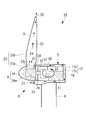
- FIG. 1 is a side view showing an example of a wind power generator to which cooling structures A to F in each embodiment described later can be applied.
- This wind power generator 1 includes a tower 4 erected on a reinforced concrete foundation 3 installed on the ground surface 2, a nacelle 5 installed at the upper end of the tower 4, and a substantially horizontal lateral rotation. And a rotor head 6 that is rotatably supported around the axis and is provided on the front end side of the nacelle 5.
- a so-called upwind type windmill in which the rotor head 6 is provided on the front end side of the nacelle 5 will be described.
- the present invention is also applicable to a downwind type windmill in which the rotor head 6 is provided on the rear end side of the nacelle 5. It will be apparent to those skilled in the art that this can be done.
- the tower 4 is a steel tube monopole type, and its cross-sectional shape is substantially circular.
- a base plate 7 made of, for example, a steel plate is fixed to the lower end portion of the tower 4, and the base plate 7 is fastened and fixed to the foundation 3 with a number of anchor bolts 8.
- a plurality of (for example, three) wind turbine blades 9 extending in the radial direction are attached to the rotor head 6.
- a generator 11 is accommodated in the nacelle 5, and the rotating shaft 12 of the rotor head 6 generates power. It is connected to the main shaft of the machine 11 through a speed increaser 13 (see FIG. 2). For this reason, the wind force of the external wind which hits the windmill blade 9 is converted into a rotational force that rotates the rotor head 6 and the rotating shaft 12, and the generator 11 is driven to generate power.
- the nacelle 5 can be swung in the horizontal direction at the upper end of the tower 4 together with the wind turbine blades 9, and is controlled by a driving device and a control device (not shown) so that the nacelle 5 is always directed efficiently in the windward direction.
- various heat generating devices such as a main bearing and a speed increaser (not shown) including the generator 11 are installed.
- a rotor hub 14 (see FIG. 2) is provided inside the rotor head 6, and this rotor hub 14 is a known hydraulic or electric motor for adjusting the pitch angle of the wind turbine blades 9 to an optimum angle corresponding to the air volume.
- a pitch driving device, a control panel and the like are incorporated.
- the pitch driving device and the control panel are also heat generating devices that generate heat during their operation.
- various electric devices 15 are also installed in the internal space S ⁇ b> 2 of the tower 4. Examples of these electrical devices 15 include heat-generating devices such as converters and transformers.
- the heat generating devices installed in the internal spaces S1 and S2 and the rotor head 6 by the cooling structures A to G in the embodiments described below.
- the heat of 11, 14, 15 is cooled.
- FIG. 2 is a schematic longitudinal sectional view of the wind turbine generator 1A according to the first embodiment of the present invention.
- This wind power generator 1A includes a cooling structure A.
- the wall body 17 constituting the nacelle 5 has a double wall structure including, for example, an outer wall 17a and an inner wall 17b provided inside the outer wall 17a with a space therebetween.
- a space between 17a and the inner wall 17b serves as a nacelle internal ventilation path 18. Outside air flows through the nacelle internal air passage 18 as cooling air.
- the wall body 17 has a double wall structure over the entire surface, but only a part of the wall body 17 may have a double structure.
- the nacelle internal air passage 18 is completely isolated from the internal space S 1 of the nacelle 5, and the generator 11 that is a heat generating device installed in the internal space S 1 is provided adjacent to the nacelle internal air passage 18. Yes. Specifically, the generator 11 is provided so as to be in close contact with the bottom surface and the rear surface of the inner wall 17 b constituting the nacelle internal ventilation path 18.
- the nacelle internal ventilation path 18 has an external air introduction port 21 for introducing external air blown from the front of the nacelle 5.
- the outside wind inlet 21 is provided so as to open toward the front, for example, at the front of the nacelle 5 directly below the rotor head 6 and in some cases on the left and right sides of the rotor head 6.
- the opening area of the outside wind introduction port 21 is set to be larger than the vertical cross-sectional area of the nacelle internal ventilation path 18, and the nacelle internal ventilation path 18 gradually becomes a passage from the outside wind introduction port 21 toward the downstream side in a side view. The area is narrow.
- the rotor head 6 is configured to include the above-described rotor hub 14 and a hub cover 14a covering the rotor hub 14, and the rotor hub 14 supports the wind turbine blades 9.
- the rotor hub 14 has a capsule structure hermetically sealed from the outside, and a pitch drive device (not shown) provided inside the rotor hub 14 is shielded from the outside air.
- a rotor head cooling air passage 23 is formed from the periphery of the rotor hub 14 to the inside of the wind turbine blade 9.
- the rotor head cooling air passage 23 is formed by connecting an internal space 23a between the rotor hub 14 and the hub cover 14a and an internal space 23b of the windmill blade, and both the internal spaces 23a and 23b are, for example, the windmill blade 9 These are communicated with each other through a communication port 23c formed at the base end portion. Further, the internal space 23 a of the rotor head 6 communicates with the nacelle internal air passage 18 through an opening-shaped cooling air introduction portion 24 opened in the front surface of the nacelle 5.
- cooling air flows into the rotor head cooling air passage 23 from the cooling air introduction portion 24.
- the exhaust port 25 is provided in the front-end
- the cooling air introduction unit 24 is provided with a blower fan 27.
- the blower fan 27 functions as an air supply means for supplying cooling air to the rotor head cooling air passage 23.
- the nacelle internal air passage 18 and the external air introduction port 21 are also a kind of air supply means for supplying cooling air to the rotor head cooling air passage 23.
- a blower device such as the circulation fan 28 may be installed in the internal space S1 of the nacelle 5.
- the cooling structure A configured as described above operates as follows.
- the wind direction of the external wind is detected, and the nacelle 5 is automatically controlled so that the front surface thereof faces upwind.
- outside wind is introduced as cooling air from the outside wind introduction port 21 opened in the front surface of the nacelle 5 into the inside of the nacelle internal ventilation path 18 as indicated by an arrow.
- This cooling air flows through the nacelle internal air passage 18 while accelerating because the passage area of the nacelle internal air passage 18 becomes narrower as it goes downstream from the external wind inlet 21, and adheres to the inner wall 17 b at that time.
- the generator 11 which is the heat generating device provided is cooled.
- the cooling air that has passed through the nacelle internal air passage 18 in this way is sent to the rotor head cooling air passage 23 via the cooling air introducing portion 24.
- the blower fan 27 provided in the cooling air introduction part 24 promotes the supply of cooling air.
- the cooling air sent to the rotor head cooling air passage 23 passes around the rotor hub 14, cools the pitch driving device and the control panel via the rotor hub 14, and finally exhausts through the inside of the wind turbine blade 9. It is discharged from the mouth 25 to the outside.
- the exhaust port 25 is formed in the wind turbine blade 9, when the wind turbine blade 9 rotates, a negative pressure acts on the exhaust port 25, and the air in the rotor head cooling air passage 23 is sucked out from the exhaust port 25.
- the flow rate and flow velocity of the cooling air flowing through the nacelle internal air passage 18 and the rotor head cooling air passage 23 increase, and the generator 11 and the rotor hub 14 are efficiently cooled. be able to.
- the rotational speed of the blower fan 27 or the ON / OFF state is automatically controlled according to the temperature of the cooling air, for example. Further, when the negative pressure acting on the exhaust port 25 due to the rotation of the wind turbine blade 9 is sufficiently large, the blower fan 27 is not necessarily provided.
- the generator 11 and the rotor hub 14 can be satisfactorily cooled with a simple structure, and the heat generating devices 11 and 14 are not directly exposed to the outside air.
- the rotor head cooling air passage 23 communicates with the nacelle internal air passage 18, and the cooling air passing through the nacelle internal air passage 18 passes through the rotor head cooling air passage 23 and is exhausted to the outside.
- the interior of the rotor head 6 can be cooled comprehensively, and the cooling structure of the entire wind power generator 1A can be simplified.
- the heat of the generator 11 and the like is widely transmitted to the inner wall 17b to increase the heat exchange rate, and the cooling performance Can be improved.
- FIG. 3 is a schematic longitudinal sectional view of a wind turbine generator 1B according to the second embodiment of the present invention.
- the wind power generator 1B includes a cooling structure B.
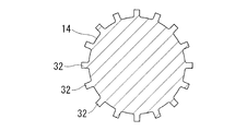
- This cooling structure B is different from the cooling structure A in the first embodiment described above in that the heat generated by the rotor hub 14 is radiated to the cooling air flowing through the rotor head cooling air passage 23 on the outer surface of the rotor hub 14.
- a heat radiation assisting means that assists, and the other parts have the same configuration.
- a heat pipe 31 having a known structure in which a hydraulic fluid such as alternative chlorofluorocarbon is sealed inside a copper pipe is used.
- the heat pipe 31 is a casing of the rotor hub 14. It arrange
- heat radiation fins 32 or ribs
- the heat dissipating fins 32 provided on the peripheral surface of the rotor hub 14 are preferably formed so that the longitudinal direction thereof is along the front-rear direction.
- the heat dissipating fins 32 are provided spirally around the rotor hub 14 and the rotor hub 14 rotates. You may comprise so that cooling air may be attracted
- the external air introduced as cooling air from the external air inlet 21 on the front surface of the nacelle 5 is the nacelle internal air passage 18 and the rotor head cooling air passage 23 as in the cooling structure A in the first embodiment.
- the heat generated by the heat generating devices such as the generator 11 and the rotor hub 14 is cooled and then discharged to the outside through the exhaust port 25.
- the heat generated by the rotor hub 14 is positively transferred to the cooling air flowing in the rotor head cooling air passage 23 by the heat transfer action of the heat pipe 31 or the heat release action of the heat radiating fins 32. 14 can be cooled.
- FIG. 5 is a schematic longitudinal sectional view of a wind turbine generator 1C according to the third embodiment of the present invention.
- the wind power generator 1C includes a cooling structure C.
- This cooling structure C is different from the cooling structure A of the first embodiment in that the rotor head cooling air passage 23 provided in the rotor head 6 is isolated from the internal space S1 of the nacelle 5.
- the internal space 23a of the rotor head 6 and the internal space 23b of the wind turbine blade 9 communicate with each other via a communication port 23c formed at the base end portion of the wind turbine blade 9 to form the rotor head cooling air passage 23.
- This is the same as the cooling structure A in that the exhaust port 25 is provided near the tip of the wind turbine blade 9.
- blower fan 36 is an air supply unit that supplies cooling air to the windmill internal ventilation path 23.
- the blower fan 36 may be fixed to the nacelle 5 side or the rotor head 6 side.
- this cooling structure C when the wind turbine blade 9 rotates, a negative pressure acts on the exhaust port 25, the cooling air in the wind turbine internal ventilation path 23 is sucked out from the exhaust port 25, and the outside air is cooled by the cooling air introduction part 35. Is sucked as cooling air into the air passage 23 inside the windmill.
- the blower fan 36 When the blower fan 36 is activated, the action of sending outside air from the cooling air introduction part 35 is further strengthened.
- the rotor hub 14 is cooled by the cooling air flowing inside the windmill internal ventilation path 23, and the air supplied for cooling is exhausted from the exhaust port 25 to the outside.
- the flow rate and flow velocity of the cooling air flowing through the wind turbine internal air passage 23 are increased by the suction action due to the negative pressure acting on the exhaust port 25 when the wind turbine blade 9 rotates and the air feeding action by the blower fan 36.
- the rotor hub 14 can be cooled efficiently.
- the advantage that the rotor hub 14 is hermetically sealed so that outside air does not enter the interior and the pitch driving device and the control panel installed inside the rotor hub 14 can be protected from corrosion, contamination, and the like is the same as that of the cooling structures A and B.
- the negative pressure which acts on the exhaust port 25 by rotation of the windmill blade 9 is large enough, it is possible to reduce the installation number of the ventilation fans 36 or to omit the ventilation fans 36.
- the blower fan 36 the rotor hub 14 can be cooled even when the wind turbine blade 9 is not rotating.
- FIG. 6 is a schematic longitudinal sectional view of a wind turbine generator 1D according to the fourth embodiment of the present invention.
- the wind power generator 1D includes a cooling structure D.
- the wall body 41 constituting the tower 4 has a double wall structure including an outer wall 41a and an inner wall 41b provided inside the outer wall 41a with a space therebetween.
- the inside of the inner wall 41b is an inner space S2
- the space between the outer wall 41a and the inner wall 41b is a tower internal air passage 42.
- the tower internal air passage 42 is isolated from the internal space S2, and an exothermic electrical device such as the converter 15a and the transformer 15b installed in the internal space S2 is adjacent to the tower internal air passage 42 (inner wall 41b). is doing.
- the wall body 41 has a double wall structure entirely, but only a part of the wall body 41 has a double structure, and a tower internal air passage 42 is partially provided, to which a converter 15a and a transformer 15b are provided. It may be adjacent.
- a nacelle internal air passage 18 similar to the cooling structures A and B of the first and second embodiments is formed inside the nacelle 5.
- the nacelle internal air passage 18 is not provided with the external air inlet 21 as in the cooling structures A and B, and the nacelle internal air passage 18 communicates with the tower internal air passage 42 via the communication portion 44.
- the nacelle internal ventilation path 18 communicates with the rotor head cooling ventilation path 23 via the cooling air introduction part 24, and the configuration in which the cooling air introduction part 24 is provided with the blower fan 27 is the same as the cooling structures A and B. It is.
- the cooling structure D configured as described above operates as follows.
- the outside wind is introduced as cooling air from the outside wind introduction port 43 into the tower internal ventilation path 42 as shown by the arrow, and flows through the tower internal ventilation path 42.
- the heat-generating converter 15a and the transformer 15b that are in close contact with the inner wall 41b and are adjacent to the tower internal air passage 42 are cooled.
- the cooling air rises in the tower internal air passage 42 and flows into the nacelle internal air passage 18 through the communication portion 44.
- the cooling air adheres closely to the inner wall 17b of the nacelle 5 similarly to the cooling structures A and B described above.
- the generator 11 as a heat generating device is cooled, and then flows into the rotor head cooling air passage 23 through the cooling air introduction part 24 while being sucked by the blower fan 27 to cool the rotor hub 14, and finally the wind turbine blade. 9 is discharged from the exhaust port 25 to the outside.
- a circulation fan 47 is installed in the tower internal air passage 42 and the cooling air flowing in the tower internal air passage 42 is positively sent to the nacelle internal air passage 18 side and the rotor head cooling air passage 23 side.
- the amount of cooling air can be increased by cooperating with the blower fan 27 provided in the cooling air introduction section 24, and the cooling performance can be improved.
- this cooling structure D not only the rotor hub 14 (pitch drive device or control panel), which is a heat generating device provided in the rotor head 6, but also the heat generating devices (converter 15a, transformer 15b) provided in the tower 4. ) And the heat generating device (generator 11) provided in the nacelle 5 can also be effectively cooled, and the internal space S2 of the tower 4 can be hermetically sealed, so that the converter 15a, the transformer 15b, etc. It is possible to protect the equipment inside the tower from being exposed to the outside air to protect it from corrosion, contamination, and the like. According to this structure, the inside of the tower 4, the nacelle 5, and the rotor head 6 can be cooled comprehensively, and the cooling structure of the entire wind power generator 1D can be simplified.
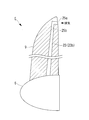
- FIG. 7 is a schematic longitudinal sectional view of a wind turbine blade 9 according to a fifth embodiment of the present invention.
- the wind turbine blade 9 can be applied to the wind power generators 1A to 1D of the first to fourth embodiments, and includes a cooling structure E.
- this cooling structure E the exhaust port of the rotor head cooling air passage 23 (23b) formed inside the wind turbine blade 9 is formed on the leeward side of the wind turbine blade 9 with respect to the wind direction. That is, for example, the exhaust port 25a is provided at the rear edge position of the wind turbine blade 9, or the exhaust port 25b is provided at the side surface position. In short, it is preferable to provide the exhaust ports 25a and 25b at the place where the negative pressure acts by the wind hitting the wind turbine blades 9.
- this cooling structure E since a high negative pressure acts on the exhaust ports 25a and 25b of the rotor head cooling air passage 23, it flows through the nacelle internal air passage 18, the rotor head cooling air passage 23, the tower internal air passage 42, and the like. It is possible to increase the flow rate of the cooling air and increase the flow rate to increase the cooling efficiency.
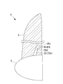
- FIG. 8 is a schematic longitudinal sectional view of a wind turbine blade 9 according to a sixth embodiment of the present invention.
- the wind turbine blade 9 can be applied to the wind power generators 1A to 1D of the first to fourth embodiments, and includes a cooling structure F.
- this cooling structure F an exhaust port 25 c of the rotor head cooling air passage 23 (23 b) formed inside the wind turbine blade 9 is formed near the root of the wind turbine blade 9.
- the exhaust port 25c is formed in a range of about 0.5 m at the farthest from the root of the wind turbine blade 9.
- the exhaust port 25c is preferably formed on the leeward side with respect to the wind direction. Further, instead of providing the exhaust port 25 c at the rear edge position of the wind turbine blade 9, the exhaust port 25 d may be provided at the side surface position of the wind turbine blade 9.
- the entire length of the rotor head cooling air passage 23 in the wind turbine blade 9 can be shortened to avoid pressure loss, and the cooling air flow velocity and flow rate can be increased to increase the cooling efficiency.
- the present invention is not limited to the above-described aspects of the first to sixth embodiments.
- Wind power generator 1, 1A to 1D Wind power generator 4 Tower 5 Nacelle 6 Rotor head 9 Windmill blade 11 Generator 14 Rotor hub (heat generating device) 14a Hub cover 18 Nacelle internal ventilation path 23 Rotor head cooling ventilation path 23a, 23b Internal space 23c Communication port 24, 35 Cooling air introduction part 25 Exhaust port 27, 36 Blower fan (air supply means) 31 Heat pipe (radiation assisting means) 32 Radiation fins (radiation assisting means) 42 Cooling structure inside tower
Landscapes
- Engineering & Computer Science (AREA)
- Life Sciences & Earth Sciences (AREA)
- Sustainable Development (AREA)
- Sustainable Energy (AREA)
- Chemical & Material Sciences (AREA)
- Combustion & Propulsion (AREA)
- Mechanical Engineering (AREA)
- General Engineering & Computer Science (AREA)
- Physics & Mathematics (AREA)
- Thermal Sciences (AREA)
- Wind Motors (AREA)
Priority Applications (2)
| Application Number | Priority Date | Filing Date | Title |
|---|---|---|---|
| EP11800861.4A EP2589804A4 (en) | 2010-06-30 | 2011-06-28 | DEVICE FOR WIND POWER PRODUCTION |
| US13/252,468 US8476784B2 (en) | 2010-06-30 | 2011-10-04 | Wind turbine generating apparatus |
Applications Claiming Priority (2)
| Application Number | Priority Date | Filing Date | Title |
|---|---|---|---|
| JP2010150582A JP5511549B2 (ja) | 2010-06-30 | 2010-06-30 | 風力発電装置 |
| JP2010-150582 | 2010-06-30 |
Related Child Applications (1)
| Application Number | Title | Priority Date | Filing Date |
|---|---|---|---|
| US13/252,468 Continuation US8476784B2 (en) | 2010-06-30 | 2011-10-04 | Wind turbine generating apparatus |
Publications (1)
| Publication Number | Publication Date |
|---|---|
| WO2012002397A1 true WO2012002397A1 (ja) | 2012-01-05 |
Family
ID=45402104
Family Applications (1)
| Application Number | Title | Priority Date | Filing Date |
|---|---|---|---|
| PCT/JP2011/064823 Ceased WO2012002397A1 (ja) | 2010-06-30 | 2011-06-28 | 風力発電装置 |
Country Status (4)
| Country | Link |
|---|---|
| US (1) | US8476784B2 (https=) |
| EP (1) | EP2589804A4 (https=) |
| JP (1) | JP5511549B2 (https=) |
| WO (1) | WO2012002397A1 (https=) |
Cited By (3)
| Publication number | Priority date | Publication date | Assignee | Title |
|---|---|---|---|---|
| CN106194609A (zh) * | 2016-08-29 | 2016-12-07 | 优利康达(天津)科技有限公司 | 一种自降温机舱 |
| CN110374826A (zh) * | 2019-07-01 | 2019-10-25 | 深圳市安思科电子科技有限公司 | 一种具有除冰和转速限制能的小型风力发电机 |
| CN115750241A (zh) * | 2022-11-03 | 2023-03-07 | 太原重工股份有限公司 | 风电机组的轮毂散热装置 |
Families Citing this family (29)
| Publication number | Priority date | Publication date | Assignee | Title |
|---|---|---|---|---|
| EP2376778B1 (en) * | 2008-12-17 | 2017-02-08 | XEMC Darwind BV | Wind turbine comprising a cooling circuit |
| EP2402593A4 (en) * | 2009-02-27 | 2013-04-10 | Mitsubishi Heavy Ind Ltd | GENERATOR DRIVEN BY THE WIND |
| JP5455508B2 (ja) * | 2009-08-28 | 2014-03-26 | 三菱重工業株式会社 | 風力発電用風車 |
| US20110103950A1 (en) * | 2009-11-04 | 2011-05-05 | General Electric Company | System and method for providing a controlled flow of fluid to or from a wind turbine blade surface |
| US9062659B2 (en) * | 2011-12-02 | 2015-06-23 | Gamesa Innovation & Technology, S.L. | Nacelle thermal conditioning system for off-shore wind turbines |
| CN103291558B (zh) * | 2012-03-01 | 2016-12-14 | 北京金风科创风电设备有限公司 | 风力发电机冷却系统、方法和风力发电机组 |
| TWI486523B (zh) | 2012-11-30 | 2015-06-01 | Ind Tech Res Inst | 應用於一風力發電機之輪轂冷卻裝置 |
| DK2806542T3 (en) * | 2013-05-22 | 2016-12-19 | Siemens Ag | Airflow Control Device |
| KR101435378B1 (ko) | 2013-05-24 | 2014-08-28 | 삼성중공업 주식회사 | 풍력 발전기 |
| KR101589537B1 (ko) * | 2014-04-24 | 2016-01-29 | 두산중공업 주식회사 | 에어튜브를 포함하는 블레이드 회전장치 |
| CN105240222A (zh) * | 2015-11-17 | 2016-01-13 | 湘电风能有限公司 | 一种风力发电机组的机头冷却系统 |
| DE102015120706B4 (de) * | 2015-11-30 | 2018-03-22 | Aerodyn Engineering Gmbh | Luftgekühlter Öltank |
| JP6650318B2 (ja) * | 2016-03-29 | 2020-02-19 | 株式会社日立製作所 | 風力発電装置 |
| US20180038351A1 (en) * | 2016-08-05 | 2018-02-08 | Siemens Aktiengesellschaft | Wind turbine with improved cooling |
| DE102017100134A1 (de) * | 2017-01-05 | 2018-07-05 | Wobben Properties Gmbh | Windenergieanlage und Verwendung eines Tropfenabscheiders in einem Windenergieanlagenrotor |
| CN107387335B (zh) * | 2017-09-11 | 2018-10-23 | 北京金风科创风电设备有限公司 | 风力发电设备、塔筒及抑制塔筒塔影效应的方法 |
| CN107605666B (zh) | 2017-09-11 | 2019-01-11 | 北京金风科创风电设备有限公司 | 具有抑制涡激振动功能的围护结构及抑制涡激振动的方法 |
| CN113302395B (zh) * | 2018-10-22 | 2024-05-31 | 泰普爱复合材料股份有限公司 | 带有加热的无龙门风力涡轮机腹板安装 |
| CN109578227A (zh) * | 2018-11-09 | 2019-04-05 | 大唐向阳风电有限公司 | 一种用于风力机组变桨控制柜的强制冷却系统 |
| ES2986897T3 (es) * | 2019-04-05 | 2024-11-13 | Siemens Gamesa Renewable Energy As | Disposición de enfriamiento para una turbina eólica |
| CN112145378A (zh) * | 2019-06-26 | 2020-12-29 | 北京金风科创风电设备有限公司 | 机舱罩和风力发电机组 |
| JP7546052B2 (ja) * | 2019-11-22 | 2024-09-05 | ヴェスタス ウィンド システムズ エー/エス | 風力タービン用ナセル |
| CN114645822B (zh) * | 2020-12-21 | 2024-12-06 | 北京金风科创风电设备有限公司 | 风力发电机组 |
| CN113048029A (zh) * | 2021-04-29 | 2021-06-29 | 华能宁夏能源有限公司 | 一种新型风力发电机用降温装置 |
| CN115149726B (zh) * | 2022-06-22 | 2023-04-25 | 江苏中车电机有限公司 | 一种风力发电机水冷系统 |
| CN115143062A (zh) * | 2022-06-28 | 2022-10-04 | 江苏携之创科技有限公司 | 一种多重调节式风力发电机舱罩 |
| CN115143037A (zh) * | 2022-08-04 | 2022-10-04 | 华仪风能有限公司 | 一种新型风力发电装置 |
| CN115822861A (zh) * | 2022-10-11 | 2023-03-21 | 中国华能集团有限公司南方分公司 | 一种调节风机叶片动态失速的结构和方法 |
| EP4357605B1 (de) * | 2022-10-17 | 2025-04-30 | Wobben Properties GmbH | Windenergieanlagen-rotorblatt und windenergieanlage |
Citations (5)
| Publication number | Priority date | Publication date | Assignee | Title |
|---|---|---|---|---|
| JP2001526357A (ja) * | 1997-12-08 | 2001-12-18 | シーメンス アクチエンゲゼルシヤフト | 風力発電設備及び風力発電設備の発電機の冷却方法 |
| JP2005069082A (ja) * | 2003-08-22 | 2005-03-17 | Fuji Heavy Ind Ltd | 風車の温度制御装置 |
| JP2007002773A (ja) * | 2005-06-24 | 2007-01-11 | Fuji Heavy Ind Ltd | 水平軸風車 |
| JP2007113518A (ja) * | 2005-10-21 | 2007-05-10 | Fuji Heavy Ind Ltd | 風車 |
| WO2009044843A1 (ja) * | 2007-10-05 | 2009-04-09 | Mitsubishi Heavy Industries, Ltd. | 風力発電装置 |
Family Cites Families (10)
| Publication number | Priority date | Publication date | Assignee | Title |
|---|---|---|---|---|
| ATE250721T1 (de) * | 1999-07-14 | 2003-10-15 | Aloys Wobben | Windenergieanlage mit einem geschlossenen kühlkreislauf |
| ITTO20020908A1 (it) * | 2002-10-17 | 2004-04-18 | Lorenzo Battisti | Sistema antighiaccio per impianti eolici. |
| DE102004064007B4 (de) * | 2004-09-24 | 2009-08-20 | Aloys Wobben | Windenergieanlage mit einer Generatorkühlung |
| US8186940B2 (en) * | 2007-09-05 | 2012-05-29 | General Electric Company | Ventilation arrangement |
| US8047774B2 (en) * | 2008-09-11 | 2011-11-01 | General Electric Company | System for heating and cooling wind turbine components |
| EP2376778B1 (en) * | 2008-12-17 | 2017-02-08 | XEMC Darwind BV | Wind turbine comprising a cooling circuit |
| US20110103950A1 (en) * | 2009-11-04 | 2011-05-05 | General Electric Company | System and method for providing a controlled flow of fluid to or from a wind turbine blade surface |
| ES2389336T3 (es) * | 2010-03-05 | 2012-10-25 | Siemens Aktiengesellschaft | Turbina eólica con sistema de distribución de medio líquido |
| JP5463218B2 (ja) * | 2010-06-30 | 2014-04-09 | 三菱重工業株式会社 | 風力発電装置 |
| BRPI1100020A2 (pt) * | 2011-01-28 | 2016-05-03 | Mitsubishi Heavy Ind Ltd | gerador de turbina eólica. |
-
2010
- 2010-06-30 JP JP2010150582A patent/JP5511549B2/ja not_active Expired - Fee Related
-
2011
- 2011-06-28 EP EP11800861.4A patent/EP2589804A4/en not_active Withdrawn
- 2011-06-28 WO PCT/JP2011/064823 patent/WO2012002397A1/ja not_active Ceased
- 2011-10-04 US US13/252,468 patent/US8476784B2/en not_active Expired - Fee Related
Patent Citations (5)
| Publication number | Priority date | Publication date | Assignee | Title |
|---|---|---|---|---|
| JP2001526357A (ja) * | 1997-12-08 | 2001-12-18 | シーメンス アクチエンゲゼルシヤフト | 風力発電設備及び風力発電設備の発電機の冷却方法 |
| JP2005069082A (ja) * | 2003-08-22 | 2005-03-17 | Fuji Heavy Ind Ltd | 風車の温度制御装置 |
| JP2007002773A (ja) * | 2005-06-24 | 2007-01-11 | Fuji Heavy Ind Ltd | 水平軸風車 |
| JP2007113518A (ja) * | 2005-10-21 | 2007-05-10 | Fuji Heavy Ind Ltd | 風車 |
| WO2009044843A1 (ja) * | 2007-10-05 | 2009-04-09 | Mitsubishi Heavy Industries, Ltd. | 風力発電装置 |
Non-Patent Citations (1)
| Title |
|---|
| See also references of EP2589804A4 * |
Cited By (4)
| Publication number | Priority date | Publication date | Assignee | Title |
|---|---|---|---|---|
| CN106194609A (zh) * | 2016-08-29 | 2016-12-07 | 优利康达(天津)科技有限公司 | 一种自降温机舱 |
| CN110374826A (zh) * | 2019-07-01 | 2019-10-25 | 深圳市安思科电子科技有限公司 | 一种具有除冰和转速限制能的小型风力发电机 |
| CN115750241A (zh) * | 2022-11-03 | 2023-03-07 | 太原重工股份有限公司 | 风电机组的轮毂散热装置 |
| CN115750241B (zh) * | 2022-11-03 | 2024-04-02 | 太原重工股份有限公司 | 风电机组的轮毂散热装置 |
Also Published As
| Publication number | Publication date |
|---|---|
| JP5511549B2 (ja) | 2014-06-04 |
| EP2589804A4 (en) | 2014-05-28 |
| US20120074711A1 (en) | 2012-03-29 |
| JP2012013006A (ja) | 2012-01-19 |
| EP2589804A1 (en) | 2013-05-08 |
| US8476784B2 (en) | 2013-07-02 |
Similar Documents
| Publication | Publication Date | Title |
|---|---|---|
| JP5511549B2 (ja) | 風力発電装置 | |
| JP5463218B2 (ja) | 風力発電装置 | |
| JP5211244B2 (ja) | 風力発電装置 | |
| US8672628B2 (en) | Wind turbine generator | |
| JP2012013006A5 (https=) | ||
| JP2012013003A5 (https=) | ||
| JP5404764B2 (ja) | 風力発電装置 | |
| JP5002309B2 (ja) | 水平軸風車 | |
| JP2012072684A (ja) | 風力発電装置 | |
| AU2009286224A1 (en) | Nacelle cooling system for wind turbine | |
| EP2535580A1 (en) | Wind-powered electrical generator | |
| TWI630316B (zh) | 風力發電裝置 | |
| US8502407B2 (en) | Wind power generating apparatus | |
| JP6074033B2 (ja) | 風力発電設備 | |
| WO2015045462A1 (ja) | 風力発電設備 |
Legal Events
| Date | Code | Title | Description |
|---|---|---|---|
| 121 | Ep: the epo has been informed by wipo that ep was designated in this application |
Ref document number: 11800861 Country of ref document: EP Kind code of ref document: A1 |
|
| WWE | Wipo information: entry into national phase |
Ref document number: 2011800861 Country of ref document: EP |
|
| NENP | Non-entry into the national phase |
Ref country code: DE |