WO2012002397A1 - Wind power generation apparatus - Google Patents
Wind power generation apparatus Download PDFInfo
- Publication number
- WO2012002397A1 WO2012002397A1 PCT/JP2011/064823 JP2011064823W WO2012002397A1 WO 2012002397 A1 WO2012002397 A1 WO 2012002397A1 JP 2011064823 W JP2011064823 W JP 2011064823W WO 2012002397 A1 WO2012002397 A1 WO 2012002397A1
- Authority
- WO
- WIPO (PCT)
- Prior art keywords
- cooling air
- air passage
- wind turbine
- rotor head
- nacelle
- Prior art date
Links
- 238000010248 power generation Methods 0.000 title abstract description 4
- 238000001816 cooling Methods 0.000 claims abstract description 164
- 230000005855 radiation Effects 0.000 claims description 10
- 230000020169 heat generation Effects 0.000 abstract 4
- 238000009423 ventilation Methods 0.000 description 18
- 238000005260 corrosion Methods 0.000 description 6
- 230000007797 corrosion Effects 0.000 description 6
- 229910000831 Steel Inorganic materials 0.000 description 2
- 238000011109 contamination Methods 0.000 description 2
- 239000000428 dust Substances 0.000 description 2
- 238000009434 installation Methods 0.000 description 2
- 230000002093 peripheral effect Effects 0.000 description 2
- 150000003839 salts Chemical class 0.000 description 2
- 239000010959 steel Substances 0.000 description 2
- RYGMFSIKBFXOCR-UHFFFAOYSA-N Copper Chemical compound [Cu] RYGMFSIKBFXOCR-UHFFFAOYSA-N 0.000 description 1
- 239000002775 capsule Substances 0.000 description 1
- KYKAJFCTULSVSH-UHFFFAOYSA-N chloro(fluoro)methane Chemical compound F[C]Cl KYKAJFCTULSVSH-UHFFFAOYSA-N 0.000 description 1
- 229910052802 copper Inorganic materials 0.000 description 1
- 239000010949 copper Substances 0.000 description 1
- 230000005611 electricity Effects 0.000 description 1
- 239000012530 fluid Substances 0.000 description 1
- 230000005404 monopole Effects 0.000 description 1
- 239000011150 reinforced concrete Substances 0.000 description 1
Images


Classifications
-
- F—MECHANICAL ENGINEERING; LIGHTING; HEATING; WEAPONS; BLASTING
- F03—MACHINES OR ENGINES FOR LIQUIDS; WIND, SPRING, OR WEIGHT MOTORS; PRODUCING MECHANICAL POWER OR A REACTIVE PROPULSIVE THRUST, NOT OTHERWISE PROVIDED FOR
- F03D—WIND MOTORS
- F03D1/00—Wind motors with rotation axis substantially parallel to the air flow entering the rotor
- F03D1/06—Rotors
- F03D1/065—Rotors characterised by their construction elements
- F03D1/0691—Rotors characterised by their construction elements of the hub
-
- F—MECHANICAL ENGINEERING; LIGHTING; HEATING; WEAPONS; BLASTING
- F03—MACHINES OR ENGINES FOR LIQUIDS; WIND, SPRING, OR WEIGHT MOTORS; PRODUCING MECHANICAL POWER OR A REACTIVE PROPULSIVE THRUST, NOT OTHERWISE PROVIDED FOR
- F03D—WIND MOTORS
- F03D1/00—Wind motors with rotation axis substantially parallel to the air flow entering the rotor
- F03D1/06—Rotors
- F03D1/065—Rotors characterised by their construction elements
- F03D1/0675—Rotors characterised by their construction elements of the blades
-
- F—MECHANICAL ENGINEERING; LIGHTING; HEATING; WEAPONS; BLASTING
- F03—MACHINES OR ENGINES FOR LIQUIDS; WIND, SPRING, OR WEIGHT MOTORS; PRODUCING MECHANICAL POWER OR A REACTIVE PROPULSIVE THRUST, NOT OTHERWISE PROVIDED FOR
- F03D—WIND MOTORS
- F03D13/00—Assembly, mounting or commissioning of wind motors; Arrangements specially adapted for transporting wind motor components
- F03D13/20—Arrangements for mounting or supporting wind motors; Masts or towers for wind motors
-
- F—MECHANICAL ENGINEERING; LIGHTING; HEATING; WEAPONS; BLASTING
- F03—MACHINES OR ENGINES FOR LIQUIDS; WIND, SPRING, OR WEIGHT MOTORS; PRODUCING MECHANICAL POWER OR A REACTIVE PROPULSIVE THRUST, NOT OTHERWISE PROVIDED FOR
- F03D—WIND MOTORS
- F03D80/00—Details, components or accessories not provided for in groups F03D1/00 - F03D17/00
- F03D80/60—Cooling or heating of wind motors
-
- F—MECHANICAL ENGINEERING; LIGHTING; HEATING; WEAPONS; BLASTING
- F03—MACHINES OR ENGINES FOR LIQUIDS; WIND, SPRING, OR WEIGHT MOTORS; PRODUCING MECHANICAL POWER OR A REACTIVE PROPULSIVE THRUST, NOT OTHERWISE PROVIDED FOR
- F03D—WIND MOTORS
- F03D80/00—Details, components or accessories not provided for in groups F03D1/00 - F03D17/00
- F03D80/80—Arrangement of components within nacelles or towers
- F03D80/88—Arrangement of components within nacelles or towers of mechanical components
-
- F—MECHANICAL ENGINEERING; LIGHTING; HEATING; WEAPONS; BLASTING
- F03—MACHINES OR ENGINES FOR LIQUIDS; WIND, SPRING, OR WEIGHT MOTORS; PRODUCING MECHANICAL POWER OR A REACTIVE PROPULSIVE THRUST, NOT OTHERWISE PROVIDED FOR
- F03D—WIND MOTORS
- F03D9/00—Adaptations of wind motors for special use; Combinations of wind motors with apparatus driven thereby; Wind motors specially adapted for installation in particular locations
- F03D9/20—Wind motors characterised by the driven apparatus
- F03D9/25—Wind motors characterised by the driven apparatus the apparatus being an electrical generator
-
- F—MECHANICAL ENGINEERING; LIGHTING; HEATING; WEAPONS; BLASTING
- F05—INDEXING SCHEMES RELATING TO ENGINES OR PUMPS IN VARIOUS SUBCLASSES OF CLASSES F01-F04
- F05B—INDEXING SCHEME RELATING TO WIND, SPRING, WEIGHT, INERTIA OR LIKE MOTORS, TO MACHINES OR ENGINES FOR LIQUIDS COVERED BY SUBCLASSES F03B, F03D AND F03G
- F05B2240/00—Components
- F05B2240/10—Stators
- F05B2240/14—Casings, housings, nacelles, gondels or the like, protecting or supporting assemblies there within
-
- F—MECHANICAL ENGINEERING; LIGHTING; HEATING; WEAPONS; BLASTING
- F05—INDEXING SCHEMES RELATING TO ENGINES OR PUMPS IN VARIOUS SUBCLASSES OF CLASSES F01-F04
- F05B—INDEXING SCHEME RELATING TO WIND, SPRING, WEIGHT, INERTIA OR LIKE MOTORS, TO MACHINES OR ENGINES FOR LIQUIDS COVERED BY SUBCLASSES F03B, F03D AND F03G
- F05B2240/00—Components
- F05B2240/20—Rotors
- F05B2240/21—Rotors for wind turbines
- F05B2240/221—Rotors for wind turbines with horizontal axis
-
- F—MECHANICAL ENGINEERING; LIGHTING; HEATING; WEAPONS; BLASTING
- F05—INDEXING SCHEMES RELATING TO ENGINES OR PUMPS IN VARIOUS SUBCLASSES OF CLASSES F01-F04
- F05B—INDEXING SCHEME RELATING TO WIND, SPRING, WEIGHT, INERTIA OR LIKE MOTORS, TO MACHINES OR ENGINES FOR LIQUIDS COVERED BY SUBCLASSES F03B, F03D AND F03G
- F05B2240/00—Components
- F05B2240/20—Rotors
- F05B2240/30—Characteristics of rotor blades, i.e. of any element transforming dynamic fluid energy to or from rotational energy and being attached to a rotor
-
- F—MECHANICAL ENGINEERING; LIGHTING; HEATING; WEAPONS; BLASTING
- F05—INDEXING SCHEMES RELATING TO ENGINES OR PUMPS IN VARIOUS SUBCLASSES OF CLASSES F01-F04
- F05B—INDEXING SCHEME RELATING TO WIND, SPRING, WEIGHT, INERTIA OR LIKE MOTORS, TO MACHINES OR ENGINES FOR LIQUIDS COVERED BY SUBCLASSES F03B, F03D AND F03G
- F05B2240/00—Components
- F05B2240/90—Mounting on supporting structures or systems
- F05B2240/91—Mounting on supporting structures or systems on a stationary structure
- F05B2240/912—Mounting on supporting structures or systems on a stationary structure on a tower
-
- F—MECHANICAL ENGINEERING; LIGHTING; HEATING; WEAPONS; BLASTING
- F05—INDEXING SCHEMES RELATING TO ENGINES OR PUMPS IN VARIOUS SUBCLASSES OF CLASSES F01-F04
- F05B—INDEXING SCHEME RELATING TO WIND, SPRING, WEIGHT, INERTIA OR LIKE MOTORS, TO MACHINES OR ENGINES FOR LIQUIDS COVERED BY SUBCLASSES F03B, F03D AND F03G
- F05B2260/00—Function
- F05B2260/20—Heat transfer, e.g. cooling
- F05B2260/201—Heat transfer, e.g. cooling by impingement of a fluid
-
- Y—GENERAL TAGGING OF NEW TECHNOLOGICAL DEVELOPMENTS; GENERAL TAGGING OF CROSS-SECTIONAL TECHNOLOGIES SPANNING OVER SEVERAL SECTIONS OF THE IPC; TECHNICAL SUBJECTS COVERED BY FORMER USPC CROSS-REFERENCE ART COLLECTIONS [XRACs] AND DIGESTS
- Y02—TECHNOLOGIES OR APPLICATIONS FOR MITIGATION OR ADAPTATION AGAINST CLIMATE CHANGE
- Y02E—REDUCTION OF GREENHOUSE GAS [GHG] EMISSIONS, RELATED TO ENERGY GENERATION, TRANSMISSION OR DISTRIBUTION
- Y02E10/00—Energy generation through renewable energy sources
- Y02E10/70—Wind energy
- Y02E10/72—Wind turbines with rotation axis in wind direction
-
- Y—GENERAL TAGGING OF NEW TECHNOLOGICAL DEVELOPMENTS; GENERAL TAGGING OF CROSS-SECTIONAL TECHNOLOGIES SPANNING OVER SEVERAL SECTIONS OF THE IPC; TECHNICAL SUBJECTS COVERED BY FORMER USPC CROSS-REFERENCE ART COLLECTIONS [XRACs] AND DIGESTS
- Y02—TECHNOLOGIES OR APPLICATIONS FOR MITIGATION OR ADAPTATION AGAINST CLIMATE CHANGE
- Y02E—REDUCTION OF GREENHOUSE GAS [GHG] EMISSIONS, RELATED TO ENERGY GENERATION, TRANSMISSION OR DISTRIBUTION
- Y02E10/00—Energy generation through renewable energy sources
- Y02E10/70—Wind energy
- Y02E10/728—Onshore wind turbines
Definitions
- the present invention relates to a wind power generator that cools the heat generated by the equipment during operation by introducing outside air.
- a standard wind turbine generator is a device that generates electricity by driving a generator by rotating a rotor head equipped with wind turbine blades by receiving wind force and increasing the speed of the rotation by a gearbox.
- the rotor head is installed on a tower erected on the ground or the like and attached to the end of a nacelle capable of yaw rotation, and is supported so as to be rotatable around a substantially horizontal lateral rotation axis. .
- Heat generators such as a generator are installed inside the nacelle, and heat generators such as converters and transformers are installed inside the tower, so in order to continue stable operation, these electrical devices There is a wind power generation apparatus in which the outside wind is taken into the tower or nacelle as cooling air.
- the rotor head has a built-in pitch driving device for adjusting the pitch angle of the wind turbine blades to an optimum angle corresponding to the air volume, and this pitch driving device also has an appropriate cooling to generate heat during its operation.
- this pitch driving device also has an appropriate cooling to generate heat during its operation.
- the interior of the rotor head has a double wall structure, and a heat generating device is installed inside the inner wall portion, and outside air outside the rotor head is There is a wind power generator that is introduced into the wall portion of the air heater to cool the heat generating device and exhausts the air supplied to the cooling air to the outside through the inside of the wind turbine blade.
- Patent Document 1 since the structure of the wind power generator disclosed in Patent Document 1 has a structure in which the outside air directly touches the heat generating device installed inside the rotor head, the inside of the rotor head is caused by foreign matters such as moisture, salt, and dust contained in the outside air. Equipment was easily corroded and fouled, which was undesirable mechanically and electrically. In order to improve this, it is necessary to provide a filter for removing foreign matters at the outside air introduction part, but pressure loss occurs due to the installation of the filter, and a sufficient amount of outside air cannot be taken in.
- the present invention has been made in view of the above circumstances, and with a simple configuration, heat-generating devices installed inside the rotor head are cooled well, and these devices are protected from corrosion, fouling, and the like.
- An object of the present invention is to provide a wind turbine generator that can be used.
- the wind power generator according to the present invention is a wind power generator that generates power by driving a generator installed inside a nacelle supported by a tower tip by a rotor head that rotates by receiving wind from the wind turbine blades.
- the rotor head includes a rotor hub that rotatably supports the wind turbine blades in the pitch direction, and a hub cover that covers the rotor hub.
- Rotor head cooling comprising a communication port provided to communicate with the internal space of the blade, an exhaust port communicating with the internal space of the wind turbine blade and the outside, and further communicating the communication port with the exhaust port
- An air passage and a cooling air introduction section for allowing outside air to flow into the rotor head cooling air passage are provided.
- the wind power generator according to the present invention is characterized in that an air supply means for supplying cooling air to the rotor head cooling air passage is provided.
- an air supply means for supplying cooling air to the rotor head cooling air passage.
- the wind turbine generator according to the present invention is characterized in that a heat radiation assisting means is provided on the outer surface of the rotor hub to assist the heat of the rotor hub being radiated to the cooling air flowing through the rotor head cooling air passage. And thereby, the heat of a heat-emitting device can be actively dissipated to cooling air, and cooling efficiency can be improved.
- the structure which formed the said exhaust port in the leeward side with respect to the wind direction of the said windmill blade may be sufficient as the wind power generator which concerns on this invention.
- the negative pressure acting on the exhaust port can be increased to increase the flow rate and flow velocity of the cooling air flowing through the rotor head cooling air passage, thereby increasing the cooling efficiency of the heat generating device.
- the exhaust port may be formed near the root of the wind turbine blade.
- the rotor head cooling air passage communicates with the nacelle internal air passage that cools the interior of the nacelle, and the cooling air passing through the nacelle internal air passage is the rotor head cooling air passage. It is characterized by exhausting to the outside through the road. According to this structure, the inside of a nacelle and the inside of a rotor head can be cooled comprehensively, and the cooling structure of the whole wind power generator can be simplified.
- the rotor head cooling air passage includes a nacelle internal air passage that cools the inside of the nacelle, and a tower interior that cools the inside of the tower where the nacelle is installed at the upper end.
- the cooling air communicated with the air passage, and the cooling air having passed through the tower internal air passage and the nacelle internal air passage passes through the rotor head cooling air passage and is exhausted to the outside.
- the heat generating devices installed inside the rotor head are cooled well, and these devices are protected from corrosion, fouling, and the like. can do.
- FIG. 1 is a schematic longitudinal sectional view of a wind turbine generator according to a first embodiment of the present invention. It is a schematic longitudinal cross-sectional view of the wind power generator concerning 2nd Embodiment of this invention. It is a longitudinal cross-sectional view which follows the IV-IV line of FIG. It is a schematic longitudinal cross-sectional view of the wind power generator which concerns on 3rd Embodiment of this invention. It is a schematic longitudinal cross-sectional view of the wind power generator concerning 4th Embodiment of this invention. It is a schematic longitudinal cross-sectional view of the windmill blade which concerns on 5th Embodiment of this invention. It is a schematic longitudinal cross-sectional view of the windmill blade which concerns on 6th Embodiment of this invention.
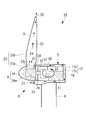
- FIG. 1 is a side view showing an example of a wind power generator to which cooling structures A to F in each embodiment described later can be applied.
- This wind power generator 1 includes a tower 4 erected on a reinforced concrete foundation 3 installed on the ground surface 2, a nacelle 5 installed at the upper end of the tower 4, and a substantially horizontal lateral rotation. And a rotor head 6 that is rotatably supported around the axis and is provided on the front end side of the nacelle 5.
- a so-called upwind type windmill in which the rotor head 6 is provided on the front end side of the nacelle 5 will be described.
- the present invention is also applicable to a downwind type windmill in which the rotor head 6 is provided on the rear end side of the nacelle 5. It will be apparent to those skilled in the art that this can be done.
- the tower 4 is a steel tube monopole type, and its cross-sectional shape is substantially circular.
- a base plate 7 made of, for example, a steel plate is fixed to the lower end portion of the tower 4, and the base plate 7 is fastened and fixed to the foundation 3 with a number of anchor bolts 8.
- a plurality of (for example, three) wind turbine blades 9 extending in the radial direction are attached to the rotor head 6.
- a generator 11 is accommodated in the nacelle 5, and the rotating shaft 12 of the rotor head 6 generates power. It is connected to the main shaft of the machine 11 through a speed increaser 13 (see FIG. 2). For this reason, the wind force of the external wind which hits the windmill blade 9 is converted into a rotational force that rotates the rotor head 6 and the rotating shaft 12, and the generator 11 is driven to generate power.
- the nacelle 5 can be swung in the horizontal direction at the upper end of the tower 4 together with the wind turbine blades 9, and is controlled by a driving device and a control device (not shown) so that the nacelle 5 is always directed efficiently in the windward direction.
- various heat generating devices such as a main bearing and a speed increaser (not shown) including the generator 11 are installed.
- a rotor hub 14 (see FIG. 2) is provided inside the rotor head 6, and this rotor hub 14 is a known hydraulic or electric motor for adjusting the pitch angle of the wind turbine blades 9 to an optimum angle corresponding to the air volume.
- a pitch driving device, a control panel and the like are incorporated.
- the pitch driving device and the control panel are also heat generating devices that generate heat during their operation.
- various electric devices 15 are also installed in the internal space S ⁇ b> 2 of the tower 4. Examples of these electrical devices 15 include heat-generating devices such as converters and transformers.
- the heat generating devices installed in the internal spaces S1 and S2 and the rotor head 6 by the cooling structures A to G in the embodiments described below.
- the heat of 11, 14, 15 is cooled.
- FIG. 2 is a schematic longitudinal sectional view of the wind turbine generator 1A according to the first embodiment of the present invention.
- This wind power generator 1A includes a cooling structure A.
- the wall body 17 constituting the nacelle 5 has a double wall structure including, for example, an outer wall 17a and an inner wall 17b provided inside the outer wall 17a with a space therebetween.
- a space between 17a and the inner wall 17b serves as a nacelle internal ventilation path 18. Outside air flows through the nacelle internal air passage 18 as cooling air.
- the wall body 17 has a double wall structure over the entire surface, but only a part of the wall body 17 may have a double structure.
- the nacelle internal air passage 18 is completely isolated from the internal space S 1 of the nacelle 5, and the generator 11 that is a heat generating device installed in the internal space S 1 is provided adjacent to the nacelle internal air passage 18. Yes. Specifically, the generator 11 is provided so as to be in close contact with the bottom surface and the rear surface of the inner wall 17 b constituting the nacelle internal ventilation path 18.
- the nacelle internal ventilation path 18 has an external air introduction port 21 for introducing external air blown from the front of the nacelle 5.
- the outside wind inlet 21 is provided so as to open toward the front, for example, at the front of the nacelle 5 directly below the rotor head 6 and in some cases on the left and right sides of the rotor head 6.
- the opening area of the outside wind introduction port 21 is set to be larger than the vertical cross-sectional area of the nacelle internal ventilation path 18, and the nacelle internal ventilation path 18 gradually becomes a passage from the outside wind introduction port 21 toward the downstream side in a side view. The area is narrow.
- the rotor head 6 is configured to include the above-described rotor hub 14 and a hub cover 14a covering the rotor hub 14, and the rotor hub 14 supports the wind turbine blades 9.
- the rotor hub 14 has a capsule structure hermetically sealed from the outside, and a pitch drive device (not shown) provided inside the rotor hub 14 is shielded from the outside air.
- a rotor head cooling air passage 23 is formed from the periphery of the rotor hub 14 to the inside of the wind turbine blade 9.
- the rotor head cooling air passage 23 is formed by connecting an internal space 23a between the rotor hub 14 and the hub cover 14a and an internal space 23b of the windmill blade, and both the internal spaces 23a and 23b are, for example, the windmill blade 9 These are communicated with each other through a communication port 23c formed at the base end portion. Further, the internal space 23 a of the rotor head 6 communicates with the nacelle internal air passage 18 through an opening-shaped cooling air introduction portion 24 opened in the front surface of the nacelle 5.
- cooling air flows into the rotor head cooling air passage 23 from the cooling air introduction portion 24.
- the exhaust port 25 is provided in the front-end
- the cooling air introduction unit 24 is provided with a blower fan 27.
- the blower fan 27 functions as an air supply means for supplying cooling air to the rotor head cooling air passage 23.
- the nacelle internal air passage 18 and the external air introduction port 21 are also a kind of air supply means for supplying cooling air to the rotor head cooling air passage 23.
- a blower device such as the circulation fan 28 may be installed in the internal space S1 of the nacelle 5.
- the cooling structure A configured as described above operates as follows.
- the wind direction of the external wind is detected, and the nacelle 5 is automatically controlled so that the front surface thereof faces upwind.
- outside wind is introduced as cooling air from the outside wind introduction port 21 opened in the front surface of the nacelle 5 into the inside of the nacelle internal ventilation path 18 as indicated by an arrow.
- This cooling air flows through the nacelle internal air passage 18 while accelerating because the passage area of the nacelle internal air passage 18 becomes narrower as it goes downstream from the external wind inlet 21, and adheres to the inner wall 17 b at that time.
- the generator 11 which is the heat generating device provided is cooled.
- the cooling air that has passed through the nacelle internal air passage 18 in this way is sent to the rotor head cooling air passage 23 via the cooling air introducing portion 24.
- the blower fan 27 provided in the cooling air introduction part 24 promotes the supply of cooling air.
- the cooling air sent to the rotor head cooling air passage 23 passes around the rotor hub 14, cools the pitch driving device and the control panel via the rotor hub 14, and finally exhausts through the inside of the wind turbine blade 9. It is discharged from the mouth 25 to the outside.
- the exhaust port 25 is formed in the wind turbine blade 9, when the wind turbine blade 9 rotates, a negative pressure acts on the exhaust port 25, and the air in the rotor head cooling air passage 23 is sucked out from the exhaust port 25.
- the flow rate and flow velocity of the cooling air flowing through the nacelle internal air passage 18 and the rotor head cooling air passage 23 increase, and the generator 11 and the rotor hub 14 are efficiently cooled. be able to.
- the rotational speed of the blower fan 27 or the ON / OFF state is automatically controlled according to the temperature of the cooling air, for example. Further, when the negative pressure acting on the exhaust port 25 due to the rotation of the wind turbine blade 9 is sufficiently large, the blower fan 27 is not necessarily provided.
- the generator 11 and the rotor hub 14 can be satisfactorily cooled with a simple structure, and the heat generating devices 11 and 14 are not directly exposed to the outside air.
- the rotor head cooling air passage 23 communicates with the nacelle internal air passage 18, and the cooling air passing through the nacelle internal air passage 18 passes through the rotor head cooling air passage 23 and is exhausted to the outside.
- the interior of the rotor head 6 can be cooled comprehensively, and the cooling structure of the entire wind power generator 1A can be simplified.
- the heat of the generator 11 and the like is widely transmitted to the inner wall 17b to increase the heat exchange rate, and the cooling performance Can be improved.
- FIG. 3 is a schematic longitudinal sectional view of a wind turbine generator 1B according to the second embodiment of the present invention.
- the wind power generator 1B includes a cooling structure B.
- This cooling structure B is different from the cooling structure A in the first embodiment described above in that the heat generated by the rotor hub 14 is radiated to the cooling air flowing through the rotor head cooling air passage 23 on the outer surface of the rotor hub 14.
- a heat radiation assisting means that assists, and the other parts have the same configuration.
- a heat pipe 31 having a known structure in which a hydraulic fluid such as alternative chlorofluorocarbon is sealed inside a copper pipe is used.
- the heat pipe 31 is a casing of the rotor hub 14. It arrange
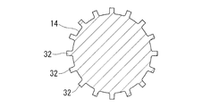
- heat radiation fins 32 or ribs
- the heat dissipating fins 32 provided on the peripheral surface of the rotor hub 14 are preferably formed so that the longitudinal direction thereof is along the front-rear direction.
- the heat dissipating fins 32 are provided spirally around the rotor hub 14 and the rotor hub 14 rotates. You may comprise so that cooling air may be attracted
- the external air introduced as cooling air from the external air inlet 21 on the front surface of the nacelle 5 is the nacelle internal air passage 18 and the rotor head cooling air passage 23 as in the cooling structure A in the first embodiment.
- the heat generated by the heat generating devices such as the generator 11 and the rotor hub 14 is cooled and then discharged to the outside through the exhaust port 25.
- the heat generated by the rotor hub 14 is positively transferred to the cooling air flowing in the rotor head cooling air passage 23 by the heat transfer action of the heat pipe 31 or the heat release action of the heat radiating fins 32. 14 can be cooled.
- FIG. 5 is a schematic longitudinal sectional view of a wind turbine generator 1C according to the third embodiment of the present invention.
- the wind power generator 1C includes a cooling structure C.
- This cooling structure C is different from the cooling structure A of the first embodiment in that the rotor head cooling air passage 23 provided in the rotor head 6 is isolated from the internal space S1 of the nacelle 5.
- the internal space 23a of the rotor head 6 and the internal space 23b of the wind turbine blade 9 communicate with each other via a communication port 23c formed at the base end portion of the wind turbine blade 9 to form the rotor head cooling air passage 23.
- This is the same as the cooling structure A in that the exhaust port 25 is provided near the tip of the wind turbine blade 9.
- blower fan 36 is an air supply unit that supplies cooling air to the windmill internal ventilation path 23.
- the blower fan 36 may be fixed to the nacelle 5 side or the rotor head 6 side.
- this cooling structure C when the wind turbine blade 9 rotates, a negative pressure acts on the exhaust port 25, the cooling air in the wind turbine internal ventilation path 23 is sucked out from the exhaust port 25, and the outside air is cooled by the cooling air introduction part 35. Is sucked as cooling air into the air passage 23 inside the windmill.
- the blower fan 36 When the blower fan 36 is activated, the action of sending outside air from the cooling air introduction part 35 is further strengthened.
- the rotor hub 14 is cooled by the cooling air flowing inside the windmill internal ventilation path 23, and the air supplied for cooling is exhausted from the exhaust port 25 to the outside.
- the flow rate and flow velocity of the cooling air flowing through the wind turbine internal air passage 23 are increased by the suction action due to the negative pressure acting on the exhaust port 25 when the wind turbine blade 9 rotates and the air feeding action by the blower fan 36.
- the rotor hub 14 can be cooled efficiently.
- the advantage that the rotor hub 14 is hermetically sealed so that outside air does not enter the interior and the pitch driving device and the control panel installed inside the rotor hub 14 can be protected from corrosion, contamination, and the like is the same as that of the cooling structures A and B.
- the negative pressure which acts on the exhaust port 25 by rotation of the windmill blade 9 is large enough, it is possible to reduce the installation number of the ventilation fans 36 or to omit the ventilation fans 36.
- the blower fan 36 the rotor hub 14 can be cooled even when the wind turbine blade 9 is not rotating.
- FIG. 6 is a schematic longitudinal sectional view of a wind turbine generator 1D according to the fourth embodiment of the present invention.
- the wind power generator 1D includes a cooling structure D.
- the wall body 41 constituting the tower 4 has a double wall structure including an outer wall 41a and an inner wall 41b provided inside the outer wall 41a with a space therebetween.
- the inside of the inner wall 41b is an inner space S2
- the space between the outer wall 41a and the inner wall 41b is a tower internal air passage 42.
- the tower internal air passage 42 is isolated from the internal space S2, and an exothermic electrical device such as the converter 15a and the transformer 15b installed in the internal space S2 is adjacent to the tower internal air passage 42 (inner wall 41b). is doing.
- the wall body 41 has a double wall structure entirely, but only a part of the wall body 41 has a double structure, and a tower internal air passage 42 is partially provided, to which a converter 15a and a transformer 15b are provided. It may be adjacent.
- a nacelle internal air passage 18 similar to the cooling structures A and B of the first and second embodiments is formed inside the nacelle 5.
- the nacelle internal air passage 18 is not provided with the external air inlet 21 as in the cooling structures A and B, and the nacelle internal air passage 18 communicates with the tower internal air passage 42 via the communication portion 44.
- the nacelle internal ventilation path 18 communicates with the rotor head cooling ventilation path 23 via the cooling air introduction part 24, and the configuration in which the cooling air introduction part 24 is provided with the blower fan 27 is the same as the cooling structures A and B. It is.
- the cooling structure D configured as described above operates as follows.
- the outside wind is introduced as cooling air from the outside wind introduction port 43 into the tower internal ventilation path 42 as shown by the arrow, and flows through the tower internal ventilation path 42.
- the heat-generating converter 15a and the transformer 15b that are in close contact with the inner wall 41b and are adjacent to the tower internal air passage 42 are cooled.
- the cooling air rises in the tower internal air passage 42 and flows into the nacelle internal air passage 18 through the communication portion 44.
- the cooling air adheres closely to the inner wall 17b of the nacelle 5 similarly to the cooling structures A and B described above.
- the generator 11 as a heat generating device is cooled, and then flows into the rotor head cooling air passage 23 through the cooling air introduction part 24 while being sucked by the blower fan 27 to cool the rotor hub 14, and finally the wind turbine blade. 9 is discharged from the exhaust port 25 to the outside.
- a circulation fan 47 is installed in the tower internal air passage 42 and the cooling air flowing in the tower internal air passage 42 is positively sent to the nacelle internal air passage 18 side and the rotor head cooling air passage 23 side.
- the amount of cooling air can be increased by cooperating with the blower fan 27 provided in the cooling air introduction section 24, and the cooling performance can be improved.
- this cooling structure D not only the rotor hub 14 (pitch drive device or control panel), which is a heat generating device provided in the rotor head 6, but also the heat generating devices (converter 15a, transformer 15b) provided in the tower 4. ) And the heat generating device (generator 11) provided in the nacelle 5 can also be effectively cooled, and the internal space S2 of the tower 4 can be hermetically sealed, so that the converter 15a, the transformer 15b, etc. It is possible to protect the equipment inside the tower from being exposed to the outside air to protect it from corrosion, contamination, and the like. According to this structure, the inside of the tower 4, the nacelle 5, and the rotor head 6 can be cooled comprehensively, and the cooling structure of the entire wind power generator 1D can be simplified.
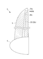
- FIG. 7 is a schematic longitudinal sectional view of a wind turbine blade 9 according to a fifth embodiment of the present invention.
- the wind turbine blade 9 can be applied to the wind power generators 1A to 1D of the first to fourth embodiments, and includes a cooling structure E.
- this cooling structure E the exhaust port of the rotor head cooling air passage 23 (23b) formed inside the wind turbine blade 9 is formed on the leeward side of the wind turbine blade 9 with respect to the wind direction. That is, for example, the exhaust port 25a is provided at the rear edge position of the wind turbine blade 9, or the exhaust port 25b is provided at the side surface position. In short, it is preferable to provide the exhaust ports 25a and 25b at the place where the negative pressure acts by the wind hitting the wind turbine blades 9.
- this cooling structure E since a high negative pressure acts on the exhaust ports 25a and 25b of the rotor head cooling air passage 23, it flows through the nacelle internal air passage 18, the rotor head cooling air passage 23, the tower internal air passage 42, and the like. It is possible to increase the flow rate of the cooling air and increase the flow rate to increase the cooling efficiency.
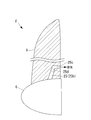
- FIG. 8 is a schematic longitudinal sectional view of a wind turbine blade 9 according to a sixth embodiment of the present invention.
- the wind turbine blade 9 can be applied to the wind power generators 1A to 1D of the first to fourth embodiments, and includes a cooling structure F.
- this cooling structure F an exhaust port 25 c of the rotor head cooling air passage 23 (23 b) formed inside the wind turbine blade 9 is formed near the root of the wind turbine blade 9.
- the exhaust port 25c is formed in a range of about 0.5 m at the farthest from the root of the wind turbine blade 9.
- the exhaust port 25c is preferably formed on the leeward side with respect to the wind direction. Further, instead of providing the exhaust port 25 c at the rear edge position of the wind turbine blade 9, the exhaust port 25 d may be provided at the side surface position of the wind turbine blade 9.
- the entire length of the rotor head cooling air passage 23 in the wind turbine blade 9 can be shortened to avoid pressure loss, and the cooling air flow velocity and flow rate can be increased to increase the cooling efficiency.
- the present invention is not limited to the above-described aspects of the first to sixth embodiments.
- Wind power generator 1, 1A to 1D Wind power generator 4 Tower 5 Nacelle 6 Rotor head 9 Windmill blade 11 Generator 14 Rotor hub (heat generating device) 14a Hub cover 18 Nacelle internal ventilation path 23 Rotor head cooling ventilation path 23a, 23b Internal space 23c Communication port 24, 35 Cooling air introduction part 25 Exhaust port 27, 36 Blower fan (air supply means) 31 Heat pipe (radiation assisting means) 32 Radiation fins (radiation assisting means) 42 Cooling structure inside tower
Abstract
Disclosed is a wind power generation apparatus wherein heat generation equipment installed on the inside of a rotor head can be satisfactorily cooled and prevented from being corroded, damaged, etc., by a simple structure. In a wind power generation apparatus (1A), a rotor head (6) which rotates by receiving outside air using windmill blades (9), drives an electric generator (11) installed on the inside of a nacelle (5), to generate electric power, and heat generation equipment (for example, a rotor hub) (14) is provided on the inside of the rotor head (6). A cooling structure (A) is characterized in that the heat generation equipment (14) is hermetically sealed from the outside; a rotor head cooling air passage (23) extends from the periphery of the heat generation equipment (14) to the inside of each windmill blade (9); a cooling air introduction portion (24) through which cooling air is introduced, and exhaust ports (25) through which the cooling air is discharged to the outside, are provided in the rotor head cooling air passage (23); and the exhaust ports (25) are formed in the windmill blades (9).
Description
本発明は、運転時における機器の発熱を、外気の導入により冷却するようにした風力発電装置に関するものである。
The present invention relates to a wind power generator that cools the heat generated by the equipment during operation by introducing outside air.
標準的な風力発電装置は、風車翼を備えたロータヘッドが風力を受けて回転し、この回転を増速機により増速する等して発電機を駆動し、発電を行う装置である。ロータヘッドは、地面等に立設されたタワーの上に設置されてヨー旋回可能なナセルの端部に取り付けられ、略水平な横方向の回転軸線周りに回転可能となるように支持されている。
A standard wind turbine generator is a device that generates electricity by driving a generator by rotating a rotor head equipped with wind turbine blades by receiving wind force and increasing the speed of the rotation by a gearbox. The rotor head is installed on a tower erected on the ground or the like and attached to the end of a nacelle capable of yaw rotation, and is supported so as to be rotatable around a substantially horizontal lateral rotation axis. .
ナセルの内部には発電機を始めとする発熱機器が設置され、タワーの内部にはコンバータや変圧器といった発熱機器が設置されているため、安定した運転を継続するためには、これらの電気機器を適切に冷却する必要があり、外風を冷却空気としてタワーやナセルの内部に取り入れるようにした風力発電装置がある。
Heat generators such as a generator are installed inside the nacelle, and heat generators such as converters and transformers are installed inside the tower, so in order to continue stable operation, these electrical devices There is a wind power generation apparatus in which the outside wind is taken into the tower or nacelle as cooling air.
また、ロータヘッドには、風車翼のピッチ角を風量に見合う最適な角度に調整するためのピッチ駆動装置が内蔵されているが、このピッチ駆動装置も、その作動時に発熱するために適切な冷却が望まれる。従来では、例えば特許文献1に開示されているように、ロータヘッドの内部を2重壁構造にし、その内側の壁部の内部に発熱機器を設置するとともに、ロータヘッドの外部の外気を、内側の壁部の内部に導入して発熱機器を冷却し、この冷却に供された空気を、風車翼の内部を経て外部に排気するようにした風力発電装置がある。
In addition, the rotor head has a built-in pitch driving device for adjusting the pitch angle of the wind turbine blades to an optimum angle corresponding to the air volume, and this pitch driving device also has an appropriate cooling to generate heat during its operation. Is desired. Conventionally, as disclosed in Patent Document 1, for example, the interior of the rotor head has a double wall structure, and a heat generating device is installed inside the inner wall portion, and outside air outside the rotor head is There is a wind power generator that is introduced into the wall portion of the air heater to cool the heat generating device and exhausts the air supplied to the cooling air to the outside through the inside of the wind turbine blade.
しかしながら、特許文献1の風力発電装置の構成では、ロータヘッドの内部に設置された発熱機器に外気が直接触れる構造であるため、外気に含まれる水分や塩分、塵埃等の異物によってロータヘッド内部の機器類の腐食、汚損等が生じやすく、機械的、電気的に好ましくなかった。これを改善するには、外気の導入部に異物除去用のフィルタを設ける必要があるが、フィルタの設置によって圧損が発生し、充分な量の外気を取り入れることができなくなってしまう。
However, since the structure of the wind power generator disclosed in Patent Document 1 has a structure in which the outside air directly touches the heat generating device installed inside the rotor head, the inside of the rotor head is caused by foreign matters such as moisture, salt, and dust contained in the outside air. Equipment was easily corroded and fouled, which was undesirable mechanically and electrically. In order to improve this, it is necessary to provide a filter for removing foreign matters at the outside air introduction part, but pressure loss occurs due to the installation of the filter, and a sufficient amount of outside air cannot be taken in.
本発明は、上記の事情に鑑みてなされたものであり、簡素な構成により、ロータヘッドの内部に設置された発熱機器類を良好に冷却するとともに、これらの機器類を腐食、汚損等から保護することのできる風力発電装置を提供することを目的とする。
The present invention has been made in view of the above circumstances, and with a simple configuration, heat-generating devices installed inside the rotor head are cooled well, and these devices are protected from corrosion, fouling, and the like. An object of the present invention is to provide a wind turbine generator that can be used.
本発明は、上記の課題を解決するため、下記の手段を採用した。
即ち、本発明に係る風力発電装置は、風車翼に外風を受けて回転するロータヘッドが、タワー先端に支持されたナセルの内部に設置された発電機を駆動して発電を行う風力発電装置において、前記ロータヘッドは、前記風車翼をピッチ方向に回動自在に支持するロータハブと、前記ロータハブを覆うハブカバーとを備え、前記風車翼は、前記ロータハブと前記ハブカバーとの間の内部空間と風車翼の内部空間とを連通するように設けられた連通口と、風車翼の内部空間と外部とを連通する排気口とを備え、さらに、前記連通口と前記排気口とを連通させるロータヘッド冷却通気路と、前記ロータヘッド冷却通気路に外気を流入させる冷却空気導入部とを備えることを特徴とする。 In order to solve the above problems, the present invention employs the following means.
That is, the wind power generator according to the present invention is a wind power generator that generates power by driving a generator installed inside a nacelle supported by a tower tip by a rotor head that rotates by receiving wind from the wind turbine blades. The rotor head includes a rotor hub that rotatably supports the wind turbine blades in the pitch direction, and a hub cover that covers the rotor hub. Rotor head cooling comprising a communication port provided to communicate with the internal space of the blade, an exhaust port communicating with the internal space of the wind turbine blade and the outside, and further communicating the communication port with the exhaust port An air passage and a cooling air introduction section for allowing outside air to flow into the rotor head cooling air passage are provided.
このような風力発電装置によれば、風車翼が回転することによって排気口に負圧が作用し、この負圧によりロータヘッド冷却通気路内の空気が吸引されて排気口から排気される。これにより、冷却空気導入部からロータヘッド冷却通気路内に新たに冷却空気が導入され、ロータハブの内部に設置された発熱機器が冷却される。冷却に供された空気は風車翼の排気口から外部に排気される。このような簡素な構成により、発熱機器(ロータハブ)を密閉構造としながら良好に冷却することができ、発熱機器を外気に直接触れさせないようにして、腐食、汚損等から保護することができる。
According to such a wind turbine generator, when the wind turbine blades rotate, a negative pressure acts on the exhaust port, and the air in the rotor head cooling air passage is sucked and exhausted from the exhaust port by this negative pressure. Thereby, cooling air is newly introduced into the rotor head cooling air passage from the cooling air introduction section, and the heat generating device installed inside the rotor hub is cooled. The air used for cooling is exhausted to the outside through the exhaust port of the wind turbine blade. With such a simple configuration, the heat generating device (rotor hub) can be cooled well while having a sealed structure, and the heat generating device can be protected from corrosion, fouling, and the like by preventing direct contact with the outside air.
また、本発明に係る風力発電装置は、前記ロータヘッド冷却通気路に冷却空気を送気する送気手段を設けたことを特徴とする。この送気手段を設けたことにより、ロータヘッド冷却通気路を流れる冷却空気の流量と流速を増大させて発熱機器の冷却効率を高めることができる。
The wind power generator according to the present invention is characterized in that an air supply means for supplying cooling air to the rotor head cooling air passage is provided. By providing this air supply means, it is possible to increase the flow rate and flow velocity of the cooling air flowing through the rotor head cooling air passage, thereby improving the cooling efficiency of the heat generating device.
さらに、本発明に係る風力発電装置は、前記ロータハブの外表面に、該ロータハブの熱が前記ロータヘッド冷却通気路を流れる冷却空気に放熱されることを補助する放熱補助手段を設けたことを特徴とする。これにより、発熱機器の熱を積極的に冷却空気に放熱させて冷却効率を高めることができる。
Furthermore, the wind turbine generator according to the present invention is characterized in that a heat radiation assisting means is provided on the outer surface of the rotor hub to assist the heat of the rotor hub being radiated to the cooling air flowing through the rotor head cooling air passage. And Thereby, the heat of a heat-emitting device can be actively dissipated to cooling air, and cooling efficiency can be improved.
そして、本発明に係る風力発電装置は、前記排気口を、前記風車翼の、風向きに対して風下側に形成した構成であってもよい。これにより、排気口に作用する負圧を大きくしてロータヘッド冷却通気路を流れる冷却空気の流量と流速を増大させ、発熱機器の冷却効率を高めることができる。
And the structure which formed the said exhaust port in the leeward side with respect to the wind direction of the said windmill blade may be sufficient as the wind power generator which concerns on this invention. As a result, the negative pressure acting on the exhaust port can be increased to increase the flow rate and flow velocity of the cooling air flowing through the rotor head cooling air passage, thereby increasing the cooling efficiency of the heat generating device.
また、上記構成に係る風力発電装置は、前記排気口を、前記風車翼の根本付近に形成してもよい。これにより、ロータヘッド冷却通気路の全長を短くして圧力損失を回避し、冷却空気の流速および流量を大きくして冷却効率を高めることができる。
In the wind turbine generator according to the above configuration, the exhaust port may be formed near the root of the wind turbine blade. Thereby, the overall length of the rotor head cooling air passage can be shortened to avoid pressure loss, and the cooling air flow rate and flow rate can be increased to increase the cooling efficiency.
さらに、本発明に係る風力発電装置は、前記ロータヘッド冷却通気路が、前記ナセル内部の冷却を行うナセル内部通気路に連通し、該ナセル内部通気路を通った冷却空気が前記ロータヘッド冷却通気路を抜けて外部に排気されるようにしたことを特徴とする。本構成によれば、ナセル内部とロータヘッド内部とを総合的に冷却することができ、風力発電装置全体の冷却構造を簡素化することができる。
Further, in the wind turbine generator according to the present invention, the rotor head cooling air passage communicates with the nacelle internal air passage that cools the interior of the nacelle, and the cooling air passing through the nacelle internal air passage is the rotor head cooling air passage. It is characterized by exhausting to the outside through the road. According to this structure, the inside of a nacelle and the inside of a rotor head can be cooled comprehensively, and the cooling structure of the whole wind power generator can be simplified.
また、本発明に係る風力発電装置は、前記ロータヘッド冷却通気路が、前記ナセル内部の冷却を行うナセル内部通気路と、前記ナセルが上端部に設置されるタワーの内部の冷却を行うタワー内部通気路とに連通し、前記タワー内部通気路と前記ナセル内部通気路を通った冷却空気が前記ロータヘッド冷却通気路を抜けて外部に排気されるようにしたことを特徴とする。本構成によれば、タワー内部とナセル内部とロータヘッド内部とを総合的に冷却することができ、風力発電装置全体の冷却構造を簡素化することができる。
Further, in the wind turbine generator according to the present invention, the rotor head cooling air passage includes a nacelle internal air passage that cools the inside of the nacelle, and a tower interior that cools the inside of the tower where the nacelle is installed at the upper end. The cooling air communicated with the air passage, and the cooling air having passed through the tower internal air passage and the nacelle internal air passage passes through the rotor head cooling air passage and is exhausted to the outside. According to this configuration, the inside of the tower, the inside of the nacelle, and the inside of the rotor head can be cooled comprehensively, and the cooling structure of the entire wind power generator can be simplified.
以上のように、本発明に係る風力発電装置によれば、簡素な構成により、ロータヘッドの内部に設置された発熱機器類を良好に冷却するとともに、これらの機器類を腐食、汚損等から保護することができる。
As described above, according to the wind turbine generator according to the present invention, with a simple configuration, the heat generating devices installed inside the rotor head are cooled well, and these devices are protected from corrosion, fouling, and the like. can do.
以下、本発明に係る風力発電装置の実施形態について図面に基づいて説明する。
図1は、後に説明する各実施形態における冷却構造A~Fを適用可能な風力発電装置の一例を示す側面図である。この風力発電装置1は、地表面2に設置された鉄筋コンクリート製の基礎3上に立設されるタワー4と、このタワー4の上端部に設置されるナセル5と、略水平な横方向の回転軸線周りに回転可能に支持されてナセル5の前端部側に設けられるロータヘッド6とを有している。本例では、ロータヘッド6がナセル5の前端部側に設けられる所謂アップウィンド型の風車について説明するが、ロータヘッド6がナセル5の後端部側に設けられるダウンウィンド型の風車にも適用できることは、当業者には明らかであろう。 Hereinafter, embodiments of a wind power generator according to the present invention will be described with reference to the drawings.
FIG. 1 is a side view showing an example of a wind power generator to which cooling structures A to F in each embodiment described later can be applied. Thiswind power generator 1 includes a tower 4 erected on a reinforced concrete foundation 3 installed on the ground surface 2, a nacelle 5 installed at the upper end of the tower 4, and a substantially horizontal lateral rotation. And a rotor head 6 that is rotatably supported around the axis and is provided on the front end side of the nacelle 5. In this example, a so-called upwind type windmill in which the rotor head 6 is provided on the front end side of the nacelle 5 will be described. However, the present invention is also applicable to a downwind type windmill in which the rotor head 6 is provided on the rear end side of the nacelle 5. It will be apparent to those skilled in the art that this can be done.
図1は、後に説明する各実施形態における冷却構造A~Fを適用可能な風力発電装置の一例を示す側面図である。この風力発電装置1は、地表面2に設置された鉄筋コンクリート製の基礎3上に立設されるタワー4と、このタワー4の上端部に設置されるナセル5と、略水平な横方向の回転軸線周りに回転可能に支持されてナセル5の前端部側に設けられるロータヘッド6とを有している。本例では、ロータヘッド6がナセル5の前端部側に設けられる所謂アップウィンド型の風車について説明するが、ロータヘッド6がナセル5の後端部側に設けられるダウンウィンド型の風車にも適用できることは、当業者には明らかであろう。 Hereinafter, embodiments of a wind power generator according to the present invention will be described with reference to the drawings.
FIG. 1 is a side view showing an example of a wind power generator to which cooling structures A to F in each embodiment described later can be applied. This
タワー4は、鋼管製のモノポール式であり、その横断面形状が略円形である。タワー4の下端部には例えば鋼板製のベースプレート7が固定され、このベースプレート7が多数のアンカーボルト8で基礎3に締結固定されている。ロータヘッド6には、放射方向に延びる複数枚(例えば3枚)の風車翼9が取り付けられており、ナセル5の内部には発電機11が収容設置され、ロータヘッド6の回転軸12が発電機11の主軸に増速機13(図2参照)を介して連結されている。このため、風車翼9に当たった外風の風力が、ロータヘッド6と回転軸12を回転させる回転力に変換され、発電機11が駆動されて発電が行われる。
The tower 4 is a steel tube monopole type, and its cross-sectional shape is substantially circular. A base plate 7 made of, for example, a steel plate is fixed to the lower end portion of the tower 4, and the base plate 7 is fastened and fixed to the foundation 3 with a number of anchor bolts 8. A plurality of (for example, three) wind turbine blades 9 extending in the radial direction are attached to the rotor head 6. A generator 11 is accommodated in the nacelle 5, and the rotating shaft 12 of the rotor head 6 generates power. It is connected to the main shaft of the machine 11 through a speed increaser 13 (see FIG. 2). For this reason, the wind force of the external wind which hits the windmill blade 9 is converted into a rotational force that rotates the rotor head 6 and the rotating shaft 12, and the generator 11 is driven to generate power.
ナセル5は、風車翼9と共に、タワー4の上端において水平方向に旋回することができ、図示しない駆動装置と制御装置により、常に風上方向に指向して効率良く発電できるように制御される。ナセル5の内部空間S1内には、発電機11を始めとし、図示しない主軸受や増速機など各種の発熱機器が設置されている。また、ロータヘッド6の内部にはロータハブ14(図2参照)が設けられ、このロータハブ14には風車翼9のピッチ角を風量に見合う最適な角度に調整するための、油圧や電動の公知のピッチ駆動装置や制御盤等が内蔵されている。このピッチ駆動装置や制御盤等も、その作動時に発熱する発熱機器である。さらに、タワー4の内部空間S2内にも各種の電気機器15が設置されている。これらの電気機器15としては、コンバータや変圧器といった発熱性のあるものが例示される。
The nacelle 5 can be swung in the horizontal direction at the upper end of the tower 4 together with the wind turbine blades 9, and is controlled by a driving device and a control device (not shown) so that the nacelle 5 is always directed efficiently in the windward direction. In the inner space S1 of the nacelle 5, various heat generating devices such as a main bearing and a speed increaser (not shown) including the generator 11 are installed. In addition, a rotor hub 14 (see FIG. 2) is provided inside the rotor head 6, and this rotor hub 14 is a known hydraulic or electric motor for adjusting the pitch angle of the wind turbine blades 9 to an optimum angle corresponding to the air volume. A pitch driving device, a control panel and the like are incorporated. The pitch driving device and the control panel are also heat generating devices that generate heat during their operation. Furthermore, various electric devices 15 are also installed in the internal space S <b> 2 of the tower 4. Examples of these electrical devices 15 include heat-generating devices such as converters and transformers.
ナセル5の内部空間S1およびタワー4の内部空間S2は密室状であるため、以下に述べる各実施形態における冷却構造A~Gにより、内部空間S1,S2およびロータヘッド6内に設置された発熱機器11,14,15の熱を冷却するようになっている。
Since the internal space S1 of the nacelle 5 and the internal space S2 of the tower 4 are closed chambers, the heat generating devices installed in the internal spaces S1 and S2 and the rotor head 6 by the cooling structures A to G in the embodiments described below. The heat of 11, 14, 15 is cooled.
(第1実施形態)
図2は、本発明の第1実施形態に係る風力発電装置1Aの概略的な縦断面図である。この風力発電装置1Aは冷却構造Aを備えている。この冷却構造Aにおいて、ナセル5を構成する壁体17は、例えば外壁17aと、この外壁17aの内側に間隔を介して設けられた内壁17bとを備えた二重壁構造となっており、外壁17aと内壁17bとの間の空間がナセル内部通気路18となっている。このナセル内部通気路18には外気が冷却空気として流通する。なお、ここでは壁体17が全面的に二重壁構造となっているが、一部だけを二重構造にしてもよい。 (First embodiment)
FIG. 2 is a schematic longitudinal sectional view of thewind turbine generator 1A according to the first embodiment of the present invention. This wind power generator 1A includes a cooling structure A. In this cooling structure A, the wall body 17 constituting the nacelle 5 has a double wall structure including, for example, an outer wall 17a and an inner wall 17b provided inside the outer wall 17a with a space therebetween. A space between 17a and the inner wall 17b serves as a nacelle internal ventilation path 18. Outside air flows through the nacelle internal air passage 18 as cooling air. Here, the wall body 17 has a double wall structure over the entire surface, but only a part of the wall body 17 may have a double structure.
図2は、本発明の第1実施形態に係る風力発電装置1Aの概略的な縦断面図である。この風力発電装置1Aは冷却構造Aを備えている。この冷却構造Aにおいて、ナセル5を構成する壁体17は、例えば外壁17aと、この外壁17aの内側に間隔を介して設けられた内壁17bとを備えた二重壁構造となっており、外壁17aと内壁17bとの間の空間がナセル内部通気路18となっている。このナセル内部通気路18には外気が冷却空気として流通する。なお、ここでは壁体17が全面的に二重壁構造となっているが、一部だけを二重構造にしてもよい。 (First embodiment)
FIG. 2 is a schematic longitudinal sectional view of the
ナセル内部通気路18は、ナセル5の内部空間S1に対して完全に隔離されており、内部空間S1に設置される発熱機器である発電機11がナセル内部通気路18に隣接させて設けられている。具体的には、発電機11が、ナセル内部通気路18を構成している内壁17bの底面と後面に密着するように設けられている。
The nacelle internal air passage 18 is completely isolated from the internal space S 1 of the nacelle 5, and the generator 11 that is a heat generating device installed in the internal space S 1 is provided adjacent to the nacelle internal air passage 18. Yes. Specifically, the generator 11 is provided so as to be in close contact with the bottom surface and the rear surface of the inner wall 17 b constituting the nacelle internal ventilation path 18.
ナセル内部通気路18は、ナセル5の前方から吹き付ける外風を導入する外風導入口21を有している。この外風導入口21は、例えばナセル5の前面の、ロータヘッド6の直下と、場合によってはロータヘッド6の左右側方の位置において、前方に向かって開くように設けられている。この外風導入口21の開口面積は、ナセル内部通気路18の縦断面積よりも大きく設定されており、側面視でナセル内部通気路18は外風導入口21から下流側に進むにしたがって次第に通路面積が狭くなっている。
The nacelle internal ventilation path 18 has an external air introduction port 21 for introducing external air blown from the front of the nacelle 5. The outside wind inlet 21 is provided so as to open toward the front, for example, at the front of the nacelle 5 directly below the rotor head 6 and in some cases on the left and right sides of the rotor head 6. The opening area of the outside wind introduction port 21 is set to be larger than the vertical cross-sectional area of the nacelle internal ventilation path 18, and the nacelle internal ventilation path 18 gradually becomes a passage from the outside wind introduction port 21 toward the downstream side in a side view. The area is narrow.
一方、ロータヘッド6は、前述のロータハブ14と、このロータハブ14を覆うハブカバー14aとを有して構成されており、ロータハブ14が風車翼9を支持している。ロータハブ14は外部に対して密閉されたカプセル構造であり、このロータハブ14の内部に設けられた図示しないピッチ駆動装置が外気から遮断されている。そして、ロータハブ14の周囲から風車翼9の内部にかけてロータヘッド冷却通気路23が形成されている。このロータヘッド冷却通気路23は、ロータハブ14とハブカバー14aとの間の内部空間23aと、風車翼の内部空間23bとが繋がったものであり、両方の内部空間23a,23bは、例えば風車翼9の基端部に形成された連通口23cを介して互いに連通している。また、ロータヘッド6の内部空間23aが、ナセル5の前面に開設された開口部状の冷却空気導入部24を経てナセル内部通気路18に連通している。
On the other hand, the rotor head 6 is configured to include the above-described rotor hub 14 and a hub cover 14a covering the rotor hub 14, and the rotor hub 14 supports the wind turbine blades 9. The rotor hub 14 has a capsule structure hermetically sealed from the outside, and a pitch drive device (not shown) provided inside the rotor hub 14 is shielded from the outside air. A rotor head cooling air passage 23 is formed from the periphery of the rotor hub 14 to the inside of the wind turbine blade 9. The rotor head cooling air passage 23 is formed by connecting an internal space 23a between the rotor hub 14 and the hub cover 14a and an internal space 23b of the windmill blade, and both the internal spaces 23a and 23b are, for example, the windmill blade 9 These are communicated with each other through a communication port 23c formed at the base end portion. Further, the internal space 23 a of the rotor head 6 communicates with the nacelle internal air passage 18 through an opening-shaped cooling air introduction portion 24 opened in the front surface of the nacelle 5.
ロータヘッド冷却通気路23内には、後述するように冷却空気導入部24から冷却空気が流入する。そして、風車翼9の先端付近に排気口25が設けられており、ここからロータヘッド冷却通気路23内の冷却空気が外部に排気される。また、冷却空気導入部24には送風ファン27が設置されている。この送風ファン27は、ロータヘッド冷却通気路23に冷却空気を送気する送気手段として機能するものである。なお、ナセル内部通気路18と外風導入口21も、ロータヘッド冷却通気路23に冷却空気を送気する送気手段の一種である。場合によっては、ナセル5の内部空間S1内に循環ファン28等の送風機器を設置してもよい。
As will be described later, cooling air flows into the rotor head cooling air passage 23 from the cooling air introduction portion 24. And the exhaust port 25 is provided in the front-end | tip vicinity of the windmill blade 9, and the cooling air in the rotor head cooling ventilation path 23 is exhausted outside from here. The cooling air introduction unit 24 is provided with a blower fan 27. The blower fan 27 functions as an air supply means for supplying cooling air to the rotor head cooling air passage 23. The nacelle internal air passage 18 and the external air introduction port 21 are also a kind of air supply means for supplying cooling air to the rotor head cooling air passage 23. In some cases, a blower device such as the circulation fan 28 may be installed in the internal space S1 of the nacelle 5.
以上のように構成された冷却構造Aは、次のように作用する。
風力発電装置1Aに外風が吹き付けた場合、この外風の風向が検知されてナセル5がその前面を風上に向けるように自動制御される。このため、ナセル5の前面に開口している外風導入口21からナセル内部通気路18の内部に矢印で示すように外風が冷却空気として導入される。この冷却空気は、ナセル内部通気路18の通路面積が外風導入口21から下流側に進むにつれて狭くなっているため加速しながらナセル内部通気路18内を流れ、その際に内壁17bに密着して設けられた発熱機器である発電機11を冷却する。 The cooling structure A configured as described above operates as follows.
When the external wind blows on thewind power generator 1A, the wind direction of the external wind is detected, and the nacelle 5 is automatically controlled so that the front surface thereof faces upwind. For this reason, outside wind is introduced as cooling air from the outside wind introduction port 21 opened in the front surface of the nacelle 5 into the inside of the nacelle internal ventilation path 18 as indicated by an arrow. This cooling air flows through the nacelle internal air passage 18 while accelerating because the passage area of the nacelle internal air passage 18 becomes narrower as it goes downstream from the external wind inlet 21, and adheres to the inner wall 17 b at that time. The generator 11 which is the heat generating device provided is cooled.
風力発電装置1Aに外風が吹き付けた場合、この外風の風向が検知されてナセル5がその前面を風上に向けるように自動制御される。このため、ナセル5の前面に開口している外風導入口21からナセル内部通気路18の内部に矢印で示すように外風が冷却空気として導入される。この冷却空気は、ナセル内部通気路18の通路面積が外風導入口21から下流側に進むにつれて狭くなっているため加速しながらナセル内部通気路18内を流れ、その際に内壁17bに密着して設けられた発熱機器である発電機11を冷却する。 The cooling structure A configured as described above operates as follows.
When the external wind blows on the
このようにナセル内部通気路18内を通過した冷却空気は、冷却空気導入部24を経てロータヘッド冷却通気路23に送気される。この時、冷却空気導入部24に設けられた送風ファン27が冷却空気の送気を促進させる。ロータヘッド冷却通気路23に送気された冷却空気は、ロータハブ14の周囲を通過してロータハブ14を介してピッチ駆動装置や制御盤を冷却し、最終的に風車翼9の内部を通って排気口25から外部に排出される。
The cooling air that has passed through the nacelle internal air passage 18 in this way is sent to the rotor head cooling air passage 23 via the cooling air introducing portion 24. At this time, the blower fan 27 provided in the cooling air introduction part 24 promotes the supply of cooling air. The cooling air sent to the rotor head cooling air passage 23 passes around the rotor hub 14, cools the pitch driving device and the control panel via the rotor hub 14, and finally exhausts through the inside of the wind turbine blade 9. It is discharged from the mouth 25 to the outside.
排気口25は風車翼9に形成されているため、風車翼9が回転することによって排気口25に負圧が作用し、ロータヘッド冷却通気路23内の空気が排気口25から吸い出される。この吸引作用と、送風ファン27による送気作用とにより、ナセル内部通気路18およびロータヘッド冷却通気路23を流れる冷却空気の流量と流速が増大し、発電機11やロータハブ14を効率良く冷却することができる。なお、送風ファン27の回転速度、あるいはON,OFF状態は、例えば冷却空気の温度に応じて自動制御される。また、風車翼9の回転により排気口25に作用する負圧が充分に大きい場合は、必ずしも送風ファン27を設けなくてもよい。
Since the exhaust port 25 is formed in the wind turbine blade 9, when the wind turbine blade 9 rotates, a negative pressure acts on the exhaust port 25, and the air in the rotor head cooling air passage 23 is sucked out from the exhaust port 25. By this suction action and the air feeding action by the blower fan 27, the flow rate and flow velocity of the cooling air flowing through the nacelle internal air passage 18 and the rotor head cooling air passage 23 increase, and the generator 11 and the rotor hub 14 are efficiently cooled. be able to. The rotational speed of the blower fan 27 or the ON / OFF state is automatically controlled according to the temperature of the cooling air, for example. Further, when the negative pressure acting on the exhaust port 25 due to the rotation of the wind turbine blade 9 is sufficiently large, the blower fan 27 is not necessarily provided.
この冷却構造Aによれば、簡素な構造により、発電機11とロータハブ14を完全に密閉構造としながら良好に冷却することができ、これらの発熱機器11,14を外気に直接触れさせないようにして、外気に含まれる水分や塩分、塵埃等の異物による腐食、汚損等から効果的に保護することができる。
According to this cooling structure A, the generator 11 and the rotor hub 14 can be satisfactorily cooled with a simple structure, and the heat generating devices 11 and 14 are not directly exposed to the outside air. In addition, it is possible to effectively protect against corrosion, fouling, and the like caused by foreign matter such as moisture, salt, and dust contained in the outside air.
また、ロータヘッド冷却通気路23はナセル内部通気路18に連通し、ナセル内部通気路18を通った冷却空気がロータヘッド冷却通気路23を抜けて外部に排気される構成であるため、ナセル5の内部とロータヘッド6の内部を総合的に冷却することができ、風力発電装置1A全体の冷却構造を簡素化することができる。なお、ナセル5の内部空間S1内に設けた循環ファン28によって内部空間S1内の空気を循環させることにより、発電機11等の熱を内壁17bに広く伝達して熱交換率を高め、冷却性能を向上させることができる。
Further, the rotor head cooling air passage 23 communicates with the nacelle internal air passage 18, and the cooling air passing through the nacelle internal air passage 18 passes through the rotor head cooling air passage 23 and is exhausted to the outside. And the interior of the rotor head 6 can be cooled comprehensively, and the cooling structure of the entire wind power generator 1A can be simplified. In addition, by circulating the air in the internal space S1 by the circulation fan 28 provided in the internal space S1 of the nacelle 5, the heat of the generator 11 and the like is widely transmitted to the inner wall 17b to increase the heat exchange rate, and the cooling performance Can be improved.
(第2実施形態)
図3は、本発明の第2実施形態に係る風力発電装置1Bの概略的な縦断面図である。この風力発電装置1Bは冷却構造Bを備えている。この冷却構造Bにおいて、前述の第1実施形態における冷却構造Aと異なる点は、ロータハブ14の外表面に、ロータハブ14の発する熱がロータヘッド冷却通気路23を流れる冷却空気に放熱されることを補助する放熱補助手段が設けられている点のみであり、他の部分は同一の構成である。ここでは、放熱補助手段の一例として、銅のパイプの内部に代替フロン等の作動液が封入された公知の構造のヒートパイプ31が用いられており、このヒートパイプ31は例えばロータハブ14のケーシングを貫通するように、ケーシングの周面と前面に配設されている。 (Second Embodiment)
FIG. 3 is a schematic longitudinal sectional view of awind turbine generator 1B according to the second embodiment of the present invention. The wind power generator 1B includes a cooling structure B. This cooling structure B is different from the cooling structure A in the first embodiment described above in that the heat generated by the rotor hub 14 is radiated to the cooling air flowing through the rotor head cooling air passage 23 on the outer surface of the rotor hub 14. It is only a point provided with a heat radiation assisting means that assists, and the other parts have the same configuration. Here, as an example of the heat radiation assisting means, a heat pipe 31 having a known structure in which a hydraulic fluid such as alternative chlorofluorocarbon is sealed inside a copper pipe is used. For example, the heat pipe 31 is a casing of the rotor hub 14. It arrange | positions at the surrounding surface and front surface of a casing so that it may penetrate.
図3は、本発明の第2実施形態に係る風力発電装置1Bの概略的な縦断面図である。この風力発電装置1Bは冷却構造Bを備えている。この冷却構造Bにおいて、前述の第1実施形態における冷却構造Aと異なる点は、ロータハブ14の外表面に、ロータハブ14の発する熱がロータヘッド冷却通気路23を流れる冷却空気に放熱されることを補助する放熱補助手段が設けられている点のみであり、他の部分は同一の構成である。ここでは、放熱補助手段の一例として、銅のパイプの内部に代替フロン等の作動液が封入された公知の構造のヒートパイプ31が用いられており、このヒートパイプ31は例えばロータハブ14のケーシングを貫通するように、ケーシングの周面と前面に配設されている。 (Second Embodiment)
FIG. 3 is a schematic longitudinal sectional view of a
あるいは、図4に示すように、ロータハブ14の周面と前面に放熱補助手段として放熱フィン32(またはリブ)を設け、ロータハブ14の表面積を増大することも考えられる。ロータハブ14の周面に設ける放熱フィン32は、その長手方向が前後方向に沿うように形成するのが好ましいが、例えば放熱フィン32をロータハブ14の周囲に螺旋状に設けて、ロータハブ14の回転により冷却空気導入部24から冷却空気が吸引されるように構成してもよい。
Alternatively, as shown in FIG. 4, it is conceivable to increase the surface area of the rotor hub 14 by providing heat radiation fins 32 (or ribs) as heat radiation assisting means on the circumferential surface and the front surface of the rotor hub 14. The heat dissipating fins 32 provided on the peripheral surface of the rotor hub 14 are preferably formed so that the longitudinal direction thereof is along the front-rear direction. For example, the heat dissipating fins 32 are provided spirally around the rotor hub 14 and the rotor hub 14 rotates. You may comprise so that cooling air may be attracted | sucked from the cooling air introduction part 24. FIG.
この冷却構造Bにおいて、ナセル5前面の外風導入口21から冷却空気として導入された外風は、第1実施形態における冷却構造Aと同様に、ナセル内部通気路18とロータヘッド冷却通気路23を通って、発電機11やロータハブ14等の発熱機器が発する熱を冷却した後、排気口25から外部に排出される。その際、ヒートパイプ31の熱移送作用、または放熱フィン32の放熱作用により、ロータハブ14が発する熱がロータヘッド冷却通気路23内を流れる冷却空気に積極的に移送されるため、より効率良くロータハブ14を冷却することができる。
In this cooling structure B, the external air introduced as cooling air from the external air inlet 21 on the front surface of the nacelle 5 is the nacelle internal air passage 18 and the rotor head cooling air passage 23 as in the cooling structure A in the first embodiment. The heat generated by the heat generating devices such as the generator 11 and the rotor hub 14 is cooled and then discharged to the outside through the exhaust port 25. At this time, the heat generated by the rotor hub 14 is positively transferred to the cooling air flowing in the rotor head cooling air passage 23 by the heat transfer action of the heat pipe 31 or the heat release action of the heat radiating fins 32. 14 can be cooled.
(第3実施形態)
図5は、本発明の第3実施形態に係る風力発電装置1Cの概略的な縦断面図である。この風力発電装置1Cは冷却構造Cを備えている。この冷却構造Cにおいて、第1実施形態の冷却構造Aと異なる点は、ロータヘッド6の内部に設けられたロータヘッド冷却通気路23がナセル5の内部空間S1とは隔絶されている点である。ロータヘッド6の内部空間23aと、風車翼9の内部空間23bとが、風車翼9の基端部に形成された連通口23cを介して互いに連通してロータヘッド冷却通気路23が構成されている点と、風車翼9の先端付近に排気口25が設けられている点は冷却構造Aと同様である。 (Third embodiment)
FIG. 5 is a schematic longitudinal sectional view of awind turbine generator 1C according to the third embodiment of the present invention. The wind power generator 1C includes a cooling structure C. This cooling structure C is different from the cooling structure A of the first embodiment in that the rotor head cooling air passage 23 provided in the rotor head 6 is isolated from the internal space S1 of the nacelle 5. . The internal space 23a of the rotor head 6 and the internal space 23b of the wind turbine blade 9 communicate with each other via a communication port 23c formed at the base end portion of the wind turbine blade 9 to form the rotor head cooling air passage 23. This is the same as the cooling structure A in that the exhaust port 25 is provided near the tip of the wind turbine blade 9.
図5は、本発明の第3実施形態に係る風力発電装置1Cの概略的な縦断面図である。この風力発電装置1Cは冷却構造Cを備えている。この冷却構造Cにおいて、第1実施形態の冷却構造Aと異なる点は、ロータヘッド6の内部に設けられたロータヘッド冷却通気路23がナセル5の内部空間S1とは隔絶されている点である。ロータヘッド6の内部空間23aと、風車翼9の内部空間23bとが、風車翼9の基端部に形成された連通口23cを介して互いに連通してロータヘッド冷却通気路23が構成されている点と、風車翼9の先端付近に排気口25が設けられている点は冷却構造Aと同様である。 (Third embodiment)
FIG. 5 is a schematic longitudinal sectional view of a
さらに、ロータヘッド6とナセル5の前面との間に、外気を風車内部通気路23内に取り入れるための、間隙状もしくは切欠き状の冷却空気導入部35が設けられる。その内側に複数の送風ファン36を設置しても良い。この送風ファン36は、風車内部通気路23に冷却空気を送気する送気手段である。送風ファン36は、ナセル5側に固定してもロータヘッド6側に固定してもよい。
Furthermore, between the rotor head 6 and the front surface of the nacelle 5, there is provided a gap-shaped or notched cooling air introducing portion 35 for taking outside air into the wind turbine internal air passage 23. A plurality of blower fans 36 may be installed inside thereof. The blower fan 36 is an air supply unit that supplies cooling air to the windmill internal ventilation path 23. The blower fan 36 may be fixed to the nacelle 5 side or the rotor head 6 side.
この冷却構造Cにおいて、風車翼9が回転することによって排気口25に負圧が作用し、風車内部通気路23内の冷却空気が排気口25から吸い出されるとともに、外気が冷却空気導入部35から風車内部通気路23内に冷却空気として吸引される。送風ファン36が作動すると、外気が冷却空気導入部35から送気される作用がさらに強められる。このように風車内部通気路23の内部を流れる冷却空気により、ロータハブ14が冷却され、冷却に供された空気は排気口25から外部に排気される。
In this cooling structure C, when the wind turbine blade 9 rotates, a negative pressure acts on the exhaust port 25, the cooling air in the wind turbine internal ventilation path 23 is sucked out from the exhaust port 25, and the outside air is cooled by the cooling air introduction part 35. Is sucked as cooling air into the air passage 23 inside the windmill. When the blower fan 36 is activated, the action of sending outside air from the cooling air introduction part 35 is further strengthened. Thus, the rotor hub 14 is cooled by the cooling air flowing inside the windmill internal ventilation path 23, and the air supplied for cooling is exhausted from the exhaust port 25 to the outside.
この冷却構造Cでは、風車翼9の回転時に排気口25に作用する負圧による吸引作用と、送風ファン36による送気作用とによって、風車内部通気路23を流れる冷却空気の流量と流速を増大させることができ、ロータハブ14を効率良く冷却することができる。ロータハブ14を密閉構造にして内部に外気が進入しないようにし、ロータハブ14の内部に設置されるピッチ駆動装置や制御盤を腐食や汚損等から保護できるという利点は冷却構造A,Bと同様である。なお、風車翼9の回転により排気口25に作用する負圧が充分に大きい場合は、送風ファン36の設置数を少なくしたり、送風ファン36を省いたりすることが考えられる。しかし、送風ファン36設けることにより、風車翼9が回転していない時でもロータハブ14を冷却することができる。
In this cooling structure C, the flow rate and flow velocity of the cooling air flowing through the wind turbine internal air passage 23 are increased by the suction action due to the negative pressure acting on the exhaust port 25 when the wind turbine blade 9 rotates and the air feeding action by the blower fan 36. The rotor hub 14 can be cooled efficiently. The advantage that the rotor hub 14 is hermetically sealed so that outside air does not enter the interior and the pitch driving device and the control panel installed inside the rotor hub 14 can be protected from corrosion, contamination, and the like is the same as that of the cooling structures A and B. . In addition, when the negative pressure which acts on the exhaust port 25 by rotation of the windmill blade 9 is large enough, it is possible to reduce the installation number of the ventilation fans 36 or to omit the ventilation fans 36. However, by providing the blower fan 36, the rotor hub 14 can be cooled even when the wind turbine blade 9 is not rotating.
(第4実施形態)
図6は、本発明の第4実施形態に係る風力発電装置1Dの概略的な縦断面図である。この風力発電装置1Dは冷却構造Dを備えている。この風力発電装置1D(冷却構造D)において、タワー4を構成する壁体41は、外壁41aと、この外壁41aの内側に間隔を介して設けられた内壁41bとを備えた二重壁構造となっており、内壁41bの内側が内側空間S2とされ、外壁41aと内壁41bとの間の空間がタワー内部通気路42とされている。 (Fourth embodiment)
FIG. 6 is a schematic longitudinal sectional view of awind turbine generator 1D according to the fourth embodiment of the present invention. The wind power generator 1D includes a cooling structure D. In this wind power generator 1D (cooling structure D), the wall body 41 constituting the tower 4 has a double wall structure including an outer wall 41a and an inner wall 41b provided inside the outer wall 41a with a space therebetween. The inside of the inner wall 41b is an inner space S2, and the space between the outer wall 41a and the inner wall 41b is a tower internal air passage 42.
図6は、本発明の第4実施形態に係る風力発電装置1Dの概略的な縦断面図である。この風力発電装置1Dは冷却構造Dを備えている。この風力発電装置1D(冷却構造D)において、タワー4を構成する壁体41は、外壁41aと、この外壁41aの内側に間隔を介して設けられた内壁41bとを備えた二重壁構造となっており、内壁41bの内側が内側空間S2とされ、外壁41aと内壁41bとの間の空間がタワー内部通気路42とされている。 (Fourth embodiment)
FIG. 6 is a schematic longitudinal sectional view of a
タワー内部通気路42は内部空間S2に対して隔離されており、内部空間S2に設置されているコンバータ15aや変圧器15bといった発熱性のある電気機器がタワー内部通気路42(内壁41b)に隣接している。なお、ここでは壁体41が全面的に二重壁構造となっているが、一部だけを二重構造にしてタワー内部通気路42を部分的に設け、これにコンバータ15a、変圧器15bを隣接させてもよい。
The tower internal air passage 42 is isolated from the internal space S2, and an exothermic electrical device such as the converter 15a and the transformer 15b installed in the internal space S2 is adjacent to the tower internal air passage 42 (inner wall 41b). is doing. Here, the wall body 41 has a double wall structure entirely, but only a part of the wall body 41 has a double structure, and a tower internal air passage 42 is partially provided, to which a converter 15a and a transformer 15b are provided. It may be adjacent.
そして、例えば地表面2に近い外壁41aの周面に1箇所、あるいは複数箇所の外風導入口43が設けられ、ここからタワー内部通気路42内に外気が冷却空気として導入されるようになっている。一方、ナセル5の内部には、先の実施形態1,2の冷却構造A,Bと同様なナセル内部通気路18が形成されている。しかし、このナセル内部通気路18には冷却構造A,Bのような外風導入口21が設けられておらず、ナセル内部通気路18は連通部44を介してタワー内部通気路42に連通している。なお、ナセル内部通気路18が冷却空気導入部24を介してロータヘッド冷却通気路23に連通し、冷却空気導入部24に送風ファン27が設けられている構成等は冷却構造A,Bと同様である。
Then, for example, one or a plurality of outside air introduction ports 43 are provided on the peripheral surface of the outer wall 41a close to the ground surface 2, and the outside air is introduced into the tower internal air passage 42 from here as cooling air. ing. On the other hand, a nacelle internal air passage 18 similar to the cooling structures A and B of the first and second embodiments is formed inside the nacelle 5. However, the nacelle internal air passage 18 is not provided with the external air inlet 21 as in the cooling structures A and B, and the nacelle internal air passage 18 communicates with the tower internal air passage 42 via the communication portion 44. ing. The nacelle internal ventilation path 18 communicates with the rotor head cooling ventilation path 23 via the cooling air introduction part 24, and the configuration in which the cooling air introduction part 24 is provided with the blower fan 27 is the same as the cooling structures A and B. It is.
以上のように構成された冷却構造Dは、次のように作用する。
風力発電装置1Dに外風が吹き付けた場合、この外風が矢印で示すように外風導入口43からタワー内部通気路42内に冷却空気として導入され、タワー内部通気路42内を流通する際に、内壁41bに密着してタワー内部通気路42に隣接している発熱性のあるコンバータ15a、変圧器15bを冷却する。その後、冷却空気はタワー内部通気路42内を上昇し、連通部44を経てナセル内部通気路18に流入し、以後は前述の冷却構造A,Bと同様に、ナセル5の内壁17bに密着して設けられた発熱機器である発電機11を冷却し、次に送風ファン27に吸引されながら冷却空気導入部24を経てロータヘッド冷却通気路23に流れてロータハブ14を冷却し、最後に風車翼9の内部を通って排気口25から外部に排出される。 The cooling structure D configured as described above operates as follows.
When outside wind blows on thewind turbine generator 1D, the outside wind is introduced as cooling air from the outside wind introduction port 43 into the tower internal ventilation path 42 as shown by the arrow, and flows through the tower internal ventilation path 42. Furthermore, the heat-generating converter 15a and the transformer 15b that are in close contact with the inner wall 41b and are adjacent to the tower internal air passage 42 are cooled. Thereafter, the cooling air rises in the tower internal air passage 42 and flows into the nacelle internal air passage 18 through the communication portion 44. Thereafter, the cooling air adheres closely to the inner wall 17b of the nacelle 5 similarly to the cooling structures A and B described above. Then, the generator 11 as a heat generating device is cooled, and then flows into the rotor head cooling air passage 23 through the cooling air introduction part 24 while being sucked by the blower fan 27 to cool the rotor hub 14, and finally the wind turbine blade. 9 is discharged from the exhaust port 25 to the outside.
風力発電装置1Dに外風が吹き付けた場合、この外風が矢印で示すように外風導入口43からタワー内部通気路42内に冷却空気として導入され、タワー内部通気路42内を流通する際に、内壁41bに密着してタワー内部通気路42に隣接している発熱性のあるコンバータ15a、変圧器15bを冷却する。その後、冷却空気はタワー内部通気路42内を上昇し、連通部44を経てナセル内部通気路18に流入し、以後は前述の冷却構造A,Bと同様に、ナセル5の内壁17bに密着して設けられた発熱機器である発電機11を冷却し、次に送風ファン27に吸引されながら冷却空気導入部24を経てロータヘッド冷却通気路23に流れてロータハブ14を冷却し、最後に風車翼9の内部を通って排気口25から外部に排出される。 The cooling structure D configured as described above operates as follows.
When outside wind blows on the
なお、場合によっては、タワー内部通気路42内に循環ファン47を設置し、タワー内部通気路42内を流れる冷却空気を積極的にナセル内部通気路18側およびロータヘッド冷却通気路23側に送り、冷却空気導入部24に設けられた送風ファン27と共働させて冷却空気量を増やし、冷却性能を向上させることができる。
In some cases, a circulation fan 47 is installed in the tower internal air passage 42 and the cooling air flowing in the tower internal air passage 42 is positively sent to the nacelle internal air passage 18 side and the rotor head cooling air passage 23 side. The amount of cooling air can be increased by cooperating with the blower fan 27 provided in the cooling air introduction section 24, and the cooling performance can be improved.
この冷却構造Dによれば、ロータヘッド6内に設けられた発熱機器であるロータハブ14(ピッチ駆動装置や制御盤)のみならず、タワー4内に設けられた発熱機器(コンバータ15a、変圧器15b)と、ナセル5内に設けられた発熱機器(発電機11)も効果的に冷却することができ、しかもタワー4の内部空間S2を密閉することができるため、コンバータ15a、変圧器15bを始めとするタワー内部機器を外気に触れさせないようにして、腐食、汚損等から保護することができる。本構成によれば、タワー4内部とナセル5内部とロータヘッド6内部とを総合的に冷却することができ、風力発電装置1D全体の冷却構造を簡素化することができる。
According to this cooling structure D, not only the rotor hub 14 (pitch drive device or control panel), which is a heat generating device provided in the rotor head 6, but also the heat generating devices (converter 15a, transformer 15b) provided in the tower 4. ) And the heat generating device (generator 11) provided in the nacelle 5 can also be effectively cooled, and the internal space S2 of the tower 4 can be hermetically sealed, so that the converter 15a, the transformer 15b, etc. It is possible to protect the equipment inside the tower from being exposed to the outside air to protect it from corrosion, contamination, and the like. According to this structure, the inside of the tower 4, the nacelle 5, and the rotor head 6 can be cooled comprehensively, and the cooling structure of the entire wind power generator 1D can be simplified.
(第5実施形態)
図7は、本発明の第5実施形態に係る風車翼9の概略的な縦断面図である。この風車翼9は、第1~第4実施形態の風力発電装置1A~1Dに適用することができ、冷却構造Eを備えている。この冷却構造Eでは、風車翼9の内部に形成されたロータヘッド冷却通気路23(23b)の排気口が、風車翼9の、風向きに対して風下側に形成されている。つまり、例えば風車翼9の後縁位置に排気口25aを設ける、あるいは側面位置に排気口25bを設ける。要するに、風車翼9に当たる風によって負圧が作用する場所に排気口25a,25bを設けるのが好ましい。 (Fifth embodiment)
FIG. 7 is a schematic longitudinal sectional view of awind turbine blade 9 according to a fifth embodiment of the present invention. The wind turbine blade 9 can be applied to the wind power generators 1A to 1D of the first to fourth embodiments, and includes a cooling structure E. In this cooling structure E, the exhaust port of the rotor head cooling air passage 23 (23b) formed inside the wind turbine blade 9 is formed on the leeward side of the wind turbine blade 9 with respect to the wind direction. That is, for example, the exhaust port 25a is provided at the rear edge position of the wind turbine blade 9, or the exhaust port 25b is provided at the side surface position. In short, it is preferable to provide the exhaust ports 25a and 25b at the place where the negative pressure acts by the wind hitting the wind turbine blades 9.
図7は、本発明の第5実施形態に係る風車翼9の概略的な縦断面図である。この風車翼9は、第1~第4実施形態の風力発電装置1A~1Dに適用することができ、冷却構造Eを備えている。この冷却構造Eでは、風車翼9の内部に形成されたロータヘッド冷却通気路23(23b)の排気口が、風車翼9の、風向きに対して風下側に形成されている。つまり、例えば風車翼9の後縁位置に排気口25aを設ける、あるいは側面位置に排気口25bを設ける。要するに、風車翼9に当たる風によって負圧が作用する場所に排気口25a,25bを設けるのが好ましい。 (Fifth embodiment)
FIG. 7 is a schematic longitudinal sectional view of a
この冷却構造Eによれば、ロータヘッド冷却通気路23の排気口25a,25bに高い負圧が作用するため、ナセル内部通気路18、ロータヘッド冷却通気路23、タワー内部通気路42等を流れる冷却空気の流速を速めるとともに流量を増大させ、冷却効率を高めることができる。
According to this cooling structure E, since a high negative pressure acts on the exhaust ports 25a and 25b of the rotor head cooling air passage 23, it flows through the nacelle internal air passage 18, the rotor head cooling air passage 23, the tower internal air passage 42, and the like. It is possible to increase the flow rate of the cooling air and increase the flow rate to increase the cooling efficiency.
(第6実施形態)
図8は、本発明の第6実施形態に係る風車翼9の概略的な縦断面図である。この風車翼9は、第1~第4実施形態の風力発電装置1A~1Dに適用することができ、冷却構造Fを備えている。この冷却構造Fでは、風車翼9の内部に形成されたロータヘッド冷却通気路23(23b)の排気口25cが、風車翼9の根本付近に形成されている。具体的には、風車翼9の根本から遠くとも0.5m位の範囲に排気口25cを形成する。しかし極端に根元に近づけて排気口25cを設けるのは風車翼9の強度上、好ましくない。なお、ここでも排気口25cは風向きに対して風下側に形成するのが望ましい。また、風車翼9の後縁位置に排気口25cを設ける代わりに、風車翼9の側面位置に排気口25dを設けてもよい。 (Sixth embodiment)
FIG. 8 is a schematic longitudinal sectional view of awind turbine blade 9 according to a sixth embodiment of the present invention. The wind turbine blade 9 can be applied to the wind power generators 1A to 1D of the first to fourth embodiments, and includes a cooling structure F. In this cooling structure F, an exhaust port 25 c of the rotor head cooling air passage 23 (23 b) formed inside the wind turbine blade 9 is formed near the root of the wind turbine blade 9. Specifically, the exhaust port 25c is formed in a range of about 0.5 m at the farthest from the root of the wind turbine blade 9. However, it is not preferable to provide the exhaust port 25 c extremely close to the base because of the strength of the wind turbine blade 9. In this case as well, the exhaust port 25c is preferably formed on the leeward side with respect to the wind direction. Further, instead of providing the exhaust port 25 c at the rear edge position of the wind turbine blade 9, the exhaust port 25 d may be provided at the side surface position of the wind turbine blade 9.
図8は、本発明の第6実施形態に係る風車翼9の概略的な縦断面図である。この風車翼9は、第1~第4実施形態の風力発電装置1A~1Dに適用することができ、冷却構造Fを備えている。この冷却構造Fでは、風車翼9の内部に形成されたロータヘッド冷却通気路23(23b)の排気口25cが、風車翼9の根本付近に形成されている。具体的には、風車翼9の根本から遠くとも0.5m位の範囲に排気口25cを形成する。しかし極端に根元に近づけて排気口25cを設けるのは風車翼9の強度上、好ましくない。なお、ここでも排気口25cは風向きに対して風下側に形成するのが望ましい。また、風車翼9の後縁位置に排気口25cを設ける代わりに、風車翼9の側面位置に排気口25dを設けてもよい。 (Sixth embodiment)
FIG. 8 is a schematic longitudinal sectional view of a
この冷却構造Fによれば、風車翼9の内部におけるロータヘッド冷却通気路23の全長を短くして圧力損失を回避し、冷却空気の流速および流量を大きくして冷却効率を高めることができる。
According to this cooling structure F, the entire length of the rotor head cooling air passage 23 in the wind turbine blade 9 can be shortened to avoid pressure loss, and the cooling air flow velocity and flow rate can be increased to increase the cooling efficiency.
なお、本発明は、上述した第1~第6実施形態の態様のみに限定されないことは言うまでもない。例えば、第1~第6実施形態の構成を適宜組み合わせるといった変更を加えることが考えられる。
Needless to say, the present invention is not limited to the above-described aspects of the first to sixth embodiments. For example, it is conceivable to make changes such as appropriately combining the configurations of the first to sixth embodiments.
1,1A~1D 風力発電装置
4 タワー
5 ナセル
6 ロータヘッド
9 風車翼
11 発電機
14 ロータハブ(発熱機器)
14a ハブカバー
18 ナセル内部通気路
23 ロータヘッド冷却通気路
23a,23b 内部空間
23c 連通口
24,35 冷却空気導入部
25 排気口
27,36 送風ファン(送気手段)
31 ヒートパイプ(放熱補助手段)
32 放熱フィン(放熱補助手段)
42 タワー内部通気路
A~F 冷却構造 1, 1A to 1DWind power generator 4 Tower 5 Nacelle 6 Rotor head 9 Windmill blade 11 Generator 14 Rotor hub (heat generating device)
14a Hub cover 18 Nacelleinternal ventilation path 23 Rotor head cooling ventilation path 23a, 23b Internal space 23c Communication port 24, 35 Cooling air introduction part 25 Exhaust port 27, 36 Blower fan (air supply means)
31 Heat pipe (radiation assisting means)
32 Radiation fins (radiation assisting means)
42 Cooling structure inside tower
4 タワー
5 ナセル
6 ロータヘッド
9 風車翼
11 発電機
14 ロータハブ(発熱機器)
14a ハブカバー
18 ナセル内部通気路
23 ロータヘッド冷却通気路
23a,23b 内部空間
23c 連通口
24,35 冷却空気導入部
25 排気口
27,36 送風ファン(送気手段)
31 ヒートパイプ(放熱補助手段)
32 放熱フィン(放熱補助手段)
42 タワー内部通気路
A~F 冷却構造 1, 1A to 1D
14a Hub cover 18 Nacelle
31 Heat pipe (radiation assisting means)
32 Radiation fins (radiation assisting means)
42 Cooling structure inside tower
Claims (7)
- 風車翼に外風を受けて回転するロータヘッドが、タワー先端に支持されたナセルの内部に設置された発電機を駆動して発電を行う風力発電装置において、
前記ロータヘッドは、前記風車翼をピッチ方向に回動自在に支持するロータハブと、前記ロータハブを覆うハブカバーとを備え、
前記風車翼は、前記ロータハブと前記ハブカバーとの間の内部空間と風車翼の内部空間とを連通するように設けられた連通口と、風車翼の内部空間と外部とを連通する排気口とを備え、
さらに、前記連通口と前記排気口とを連通させるロータヘッド冷却通気路と、前記ロータヘッド冷却通気路に外気を流入させる冷却空気導入部とを備える風力発電装置。 In a wind turbine generator that generates power by driving a generator installed inside a nacelle supported at the tip of a tower, a rotor head that rotates by receiving wind from the wind turbine blades,
The rotor head includes a rotor hub that rotatably supports the wind turbine blades in a pitch direction, and a hub cover that covers the rotor hub,
The wind turbine blade includes a communication port provided so as to communicate an internal space between the rotor hub and the hub cover and an internal space of the wind turbine blade, and an exhaust port communicating the internal space of the wind turbine blade and the outside. Prepared,
Furthermore, a wind turbine generator comprising a rotor head cooling air passage that allows the communication port and the exhaust port to communicate with each other, and a cooling air introduction portion that allows outside air to flow into the rotor head cooling air passage. - 前記ロータヘッド冷却通気路に冷却空気を送気する送気手段を設けた請求項1に記載の風力発電装置。 The wind turbine generator according to claim 1, further comprising an air supply means for supplying cooling air to the rotor head cooling air passage.
- 前記ロータハブの外表面に、該ロータハブの熱が前記ロータヘッド冷却通気路を流れる冷却空気に放熱されることを補助する放熱補助手段を設けた請求項1または2に記載の風力発電装置。 The wind turbine generator according to claim 1 or 2, wherein a heat radiation assisting means for assisting heat radiation of the heat of the rotor hub to the cooling air flowing through the rotor head cooling air passage is provided on the outer surface of the rotor hub.
- 前記排気口を、前記風車翼の、風向きに対して風下側に形成した請求項1~3のいずれかに記載の風力発電装置。 The wind turbine generator according to any one of claims 1 to 3, wherein the exhaust port is formed on a leeward side of the wind turbine blade with respect to a wind direction.
- 前記排気口を、前記風車翼の根本付近に形成した請求項4に記載の風力発電装置。 The wind turbine generator according to claim 4, wherein the exhaust port is formed near a root of the wind turbine blade.
- 前記ロータヘッド冷却通気路は、前記ナセル内部の冷却を行うナセル内部通気路に連通し、該ナセル内部通気路を通った冷却空気が前記ロータヘッド冷却通気路を抜けて外部に排気されるようにした請求項1~5のいずれかに記載の風力発電装置。 The rotor head cooling air passage communicates with a nacelle internal air passage that cools the nacelle, and cooling air passing through the nacelle internal air passage passes through the rotor head cooling air passage and is exhausted to the outside. The wind power generator according to any one of claims 1 to 5.
- 前記ロータヘッド冷却通気路は、前記ナセル内部の冷却を行うナセル内部通気路と、前記ナセルが上端部に設置されるタワーの内部の冷却を行うタワー内部通気路とに連通し、前記タワー内部通気路と前記ナセル内部通気路を通った冷却空気が前記ロータヘッド冷却通気路を抜けて外部に排気されるようにした請求項1~5のいずれかに記載の風力発電装置。 The rotor head cooling air passage communicates with a nacelle internal air passage that cools the interior of the nacelle and a tower internal air passage that cools the interior of the tower where the nacelle is installed at the upper end, and the tower internal air passage The wind power generator according to any one of claims 1 to 5, wherein cooling air passing through a passage and the nacelle internal air passage passes through the rotor head cooling air passage and is exhausted to the outside.
Priority Applications (2)
| Application Number | Priority Date | Filing Date | Title |
|---|---|---|---|
| EP11800861.4A EP2589804A4 (en) | 2010-06-30 | 2011-06-28 | Wind power generation apparatus |
| US13/252,468 US8476784B2 (en) | 2010-06-30 | 2011-10-04 | Wind turbine generating apparatus |
Applications Claiming Priority (2)
| Application Number | Priority Date | Filing Date | Title |
|---|---|---|---|
| JP2010-150582 | 2010-06-30 | ||
| JP2010150582A JP5511549B2 (en) | 2010-06-30 | 2010-06-30 | Wind power generator |
Related Child Applications (1)
| Application Number | Title | Priority Date | Filing Date |
|---|---|---|---|
| US13/252,468 Continuation US8476784B2 (en) | 2010-06-30 | 2011-10-04 | Wind turbine generating apparatus |
Publications (1)
| Publication Number | Publication Date |
|---|---|
| WO2012002397A1 true WO2012002397A1 (en) | 2012-01-05 |
Family
ID=45402104
Family Applications (1)
| Application Number | Title | Priority Date | Filing Date |
|---|---|---|---|
| PCT/JP2011/064823 WO2012002397A1 (en) | 2010-06-30 | 2011-06-28 | Wind power generation apparatus |
Country Status (4)
| Country | Link |
|---|---|
| US (1) | US8476784B2 (en) |
| EP (1) | EP2589804A4 (en) |
| JP (1) | JP5511549B2 (en) |
| WO (1) | WO2012002397A1 (en) |
Cited By (3)
| Publication number | Priority date | Publication date | Assignee | Title |
|---|---|---|---|---|
| CN106194609A (en) * | 2016-08-29 | 2016-12-07 | 优利康达(天津)科技有限公司 | A kind of from lowering the temperature cabin |
| CN110374826A (en) * | 2019-07-01 | 2019-10-25 | 深圳市安思科电子科技有限公司 | A kind of small-sized wind power generator with deicing and revolving speed limitation energy |
| CN115750241A (en) * | 2022-11-03 | 2023-03-07 | 太原重工股份有限公司 | Hub heat dissipation device of wind turbine generator |
Families Citing this family (23)
| Publication number | Priority date | Publication date | Assignee | Title |
|---|---|---|---|---|
| US9228566B2 (en) * | 2008-12-17 | 2016-01-05 | Xemc Darwind Bv | Wind turbine comprising a cooling circuit |
| CN102149919A (en) * | 2009-02-27 | 2011-08-10 | 三菱重工业株式会社 | Wind driven generator |
| JP5455508B2 (en) * | 2009-08-28 | 2014-03-26 | 三菱重工業株式会社 | Wind turbine for wind power generation |
| US20110103950A1 (en) * | 2009-11-04 | 2011-05-05 | General Electric Company | System and method for providing a controlled flow of fluid to or from a wind turbine blade surface |
| US9062659B2 (en) * | 2011-12-02 | 2015-06-23 | Gamesa Innovation & Technology, S.L. | Nacelle thermal conditioning system for off-shore wind turbines |
| CN103291558B (en) * | 2012-03-01 | 2016-12-14 | 北京金风科创风电设备有限公司 | Cooling system of wind driven generator, method and wind power generating set |
| TWI486523B (en) | 2012-11-30 | 2015-06-01 | Ind Tech Res Inst | Hub cooling apparatus adapted to wind power generator |
| DK2806542T3 (en) * | 2013-05-22 | 2016-12-19 | Siemens Ag | Airflow Control Device |
| KR101435378B1 (en) | 2013-05-24 | 2014-08-28 | 삼성중공업 주식회사 | Wind power generator |
| KR101589537B1 (en) * | 2014-04-24 | 2016-01-29 | 두산중공업 주식회사 | Blade rotating device having airtube |
| CN105240222A (en) * | 2015-11-17 | 2016-01-13 | 湘电风能有限公司 | Nose cooling system for wind generating set |
| DE102015120706B4 (en) * | 2015-11-30 | 2018-03-22 | Aerodyn Engineering Gmbh | Air-cooled oil tank |
| JP6650318B2 (en) * | 2016-03-29 | 2020-02-19 | 株式会社日立製作所 | Wind power generator |
| US20180038351A1 (en) * | 2016-08-05 | 2018-02-08 | Siemens Aktiengesellschaft | Wind turbine with improved cooling |
| DE102017100134A1 (en) * | 2017-01-05 | 2018-07-05 | Wobben Properties Gmbh | Wind turbine and use of a mist eliminator in a wind turbine rotor |
| CN107605666B (en) * | 2017-09-11 | 2019-01-11 | 北京金风科创风电设备有限公司 | Envelope structure with vortex-induced vibration inhibiting function and method for inhibiting vortex-induced vibration |
| CN107387335B (en) * | 2017-09-11 | 2018-10-23 | 北京金风科创风电设备有限公司 | Wind power generation equipment, tower barrel and method for inhibiting tower shadow effect of tower barrel |
| JP2022508957A (en) * | 2018-10-22 | 2022-01-19 | ティーピーアイ コンポジッツ,インコーポレーティッド | Installation of gantry-free wind turbine webs with heating |
| CN109578227A (en) * | 2018-11-09 | 2019-04-05 | 大唐向阳风电有限公司 | A kind of pressure cooling system for Wind turbine pitch control cabinet |
| EP3719313A1 (en) * | 2019-04-05 | 2020-10-07 | Siemens Gamesa Renewable Energy A/S | Cooling arrangement for a wind turbine |
| CN112145378A (en) * | 2019-06-26 | 2020-12-29 | 北京金风科创风电设备有限公司 | Cabin cover and wind generating set |
| JP2023503905A (en) * | 2019-11-22 | 2023-02-01 | ヴェスタス ウィンド システムズ エー/エス | nacelle for wind turbine |
| CN115149726B (en) * | 2022-06-22 | 2023-04-25 | 江苏中车电机有限公司 | Water cooling system of wind driven generator |
Citations (5)
| Publication number | Priority date | Publication date | Assignee | Title |
|---|---|---|---|---|
| JP2001526357A (en) * | 1997-12-08 | 2001-12-18 | シーメンス アクチエンゲゼルシヤフト | Wind power generation facility and method for cooling generator of wind power generation facility |
| JP2005069082A (en) * | 2003-08-22 | 2005-03-17 | Fuji Heavy Ind Ltd | Temperature controller of windmill |
| JP2007002773A (en) * | 2005-06-24 | 2007-01-11 | Fuji Heavy Ind Ltd | Horizontal shaft wind mill |
| JP2007113518A (en) * | 2005-10-21 | 2007-05-10 | Fuji Heavy Ind Ltd | Windmill |
| WO2009044843A1 (en) * | 2007-10-05 | 2009-04-09 | Mitsubishi Heavy Industries, Ltd. | Wind driven electric power generator |
Family Cites Families (10)
| Publication number | Priority date | Publication date | Assignee | Title |
|---|---|---|---|---|
| US6676122B1 (en) * | 1999-07-14 | 2004-01-13 | Aloys Wobben | Wind energy facility with a closed cooling circuit |
| ITTO20020908A1 (en) * | 2002-10-17 | 2004-04-18 | Lorenzo Battisti | ANTI-ICE SYSTEM FOR WIND SYSTEMS. |
| DE102004064007B4 (en) * | 2004-09-24 | 2009-08-20 | Aloys Wobben | Wind turbine with a generator cooling |
| US8186940B2 (en) * | 2007-09-05 | 2012-05-29 | General Electric Company | Ventilation arrangement |
| US8047774B2 (en) * | 2008-09-11 | 2011-11-01 | General Electric Company | System for heating and cooling wind turbine components |
| US9228566B2 (en) * | 2008-12-17 | 2016-01-05 | Xemc Darwind Bv | Wind turbine comprising a cooling circuit |
| US20110103950A1 (en) * | 2009-11-04 | 2011-05-05 | General Electric Company | System and method for providing a controlled flow of fluid to or from a wind turbine blade surface |
| ES2389336T3 (en) * | 2010-03-05 | 2012-10-25 | Siemens Aktiengesellschaft | Wind turbine with liquid medium distribution system |
| JP5463218B2 (en) * | 2010-06-30 | 2014-04-09 | 三菱重工業株式会社 | Wind power generator |
| CN102753821A (en) * | 2011-01-28 | 2012-10-24 | 三菱重工业株式会社 | Wind turbine generator |
-
2010
- 2010-06-30 JP JP2010150582A patent/JP5511549B2/en not_active Expired - Fee Related
-
2011
- 2011-06-28 WO PCT/JP2011/064823 patent/WO2012002397A1/en active Application Filing
- 2011-06-28 EP EP11800861.4A patent/EP2589804A4/en not_active Withdrawn
- 2011-10-04 US US13/252,468 patent/US8476784B2/en active Active
Patent Citations (5)
| Publication number | Priority date | Publication date | Assignee | Title |
|---|---|---|---|---|
| JP2001526357A (en) * | 1997-12-08 | 2001-12-18 | シーメンス アクチエンゲゼルシヤフト | Wind power generation facility and method for cooling generator of wind power generation facility |
| JP2005069082A (en) * | 2003-08-22 | 2005-03-17 | Fuji Heavy Ind Ltd | Temperature controller of windmill |
| JP2007002773A (en) * | 2005-06-24 | 2007-01-11 | Fuji Heavy Ind Ltd | Horizontal shaft wind mill |
| JP2007113518A (en) * | 2005-10-21 | 2007-05-10 | Fuji Heavy Ind Ltd | Windmill |
| WO2009044843A1 (en) * | 2007-10-05 | 2009-04-09 | Mitsubishi Heavy Industries, Ltd. | Wind driven electric power generator |
Non-Patent Citations (1)
| Title |
|---|
| See also references of EP2589804A4 * |
Cited By (4)
| Publication number | Priority date | Publication date | Assignee | Title |
|---|---|---|---|---|
| CN106194609A (en) * | 2016-08-29 | 2016-12-07 | 优利康达(天津)科技有限公司 | A kind of from lowering the temperature cabin |
| CN110374826A (en) * | 2019-07-01 | 2019-10-25 | 深圳市安思科电子科技有限公司 | A kind of small-sized wind power generator with deicing and revolving speed limitation energy |
| CN115750241A (en) * | 2022-11-03 | 2023-03-07 | 太原重工股份有限公司 | Hub heat dissipation device of wind turbine generator |
| CN115750241B (en) * | 2022-11-03 | 2024-04-02 | 太原重工股份有限公司 | Hub heat abstractor of wind turbine generator system |
Also Published As
| Publication number | Publication date |
|---|---|
| JP2012013006A (en) | 2012-01-19 |
| US20120074711A1 (en) | 2012-03-29 |
| EP2589804A4 (en) | 2014-05-28 |
| JP5511549B2 (en) | 2014-06-04 |
| EP2589804A1 (en) | 2013-05-08 |
| US8476784B2 (en) | 2013-07-02 |
Similar Documents
| Publication | Publication Date | Title |
|---|---|---|
| JP5511549B2 (en) | Wind power generator | |
| JP5463218B2 (en) | Wind power generator | |
| JP5211244B2 (en) | Wind power generator | |
| US8672628B2 (en) | Wind turbine generator | |
| JP2012013006A5 (en) | ||
| JP5550508B2 (en) | Wind power generator | |
| JP2012013003A5 (en) | ||
| JP5404764B2 (en) | Wind power generator | |
| JP5002309B2 (en) | Horizontal axis windmill | |
| EP2535580A1 (en) | Wind-powered electrical generator | |
| CA2814438C (en) | Wind energy installation having a synchronous generator, and slowly rotating synchronous generator | |
| TWI630316B (en) | Wind power generator | |
| US8502407B2 (en) | Wind power generating apparatus | |
| JP6357307B2 (en) | Wind power generation equipment | |
| JP6074033B2 (en) | Wind power generation equipment |
Legal Events
| Date | Code | Title | Description |
|---|---|---|---|
| 121 | Ep: the epo has been informed by wipo that ep was designated in this application |
Ref document number: 11800861 Country of ref document: EP Kind code of ref document: A1 |
|
| WWE | Wipo information: entry into national phase |
Ref document number: 2011800861 Country of ref document: EP |
|
| NENP | Non-entry into the national phase |
Ref country code: DE |