WO2011155100A1 - スパッタリング装置の生産復帰方法 - Google Patents
スパッタリング装置の生産復帰方法 Download PDFInfo
- Publication number
- WO2011155100A1 WO2011155100A1 PCT/JP2011/000603 JP2011000603W WO2011155100A1 WO 2011155100 A1 WO2011155100 A1 WO 2011155100A1 JP 2011000603 W JP2011000603 W JP 2011000603W WO 2011155100 A1 WO2011155100 A1 WO 2011155100A1
- Authority
- WO
- WIPO (PCT)
- Prior art keywords
- vacuum chamber
- temperature
- target
- sputtering
- baking
- Prior art date
- Legal status (The legal status is an assumption and is not a legal conclusion. Google has not performed a legal analysis and makes no representation as to the accuracy of the status listed.)
- Ceased
Links
Images
Classifications
-
- C—CHEMISTRY; METALLURGY
- C23—COATING METALLIC MATERIAL; COATING MATERIAL WITH METALLIC MATERIAL; CHEMICAL SURFACE TREATMENT; DIFFUSION TREATMENT OF METALLIC MATERIAL; COATING BY VACUUM EVAPORATION, BY SPUTTERING, BY ION IMPLANTATION OR BY CHEMICAL VAPOUR DEPOSITION, IN GENERAL; INHIBITING CORROSION OF METALLIC MATERIAL OR INCRUSTATION IN GENERAL
- C23C—COATING METALLIC MATERIAL; COATING MATERIAL WITH METALLIC MATERIAL; SURFACE TREATMENT OF METALLIC MATERIAL BY DIFFUSION INTO THE SURFACE, BY CHEMICAL CONVERSION OR SUBSTITUTION; COATING BY VACUUM EVAPORATION, BY SPUTTERING, BY ION IMPLANTATION OR BY CHEMICAL VAPOUR DEPOSITION, IN GENERAL
- C23C14/00—Coating by vacuum evaporation, by sputtering or by ion implantation of the coating forming material
- C23C14/22—Coating by vacuum evaporation, by sputtering or by ion implantation of the coating forming material characterised by the process of coating
- C23C14/34—Sputtering
- C23C14/35—Sputtering by application of a magnetic field, e.g. magnetron sputtering
-
- C—CHEMISTRY; METALLURGY
- C23—COATING METALLIC MATERIAL; COATING MATERIAL WITH METALLIC MATERIAL; CHEMICAL SURFACE TREATMENT; DIFFUSION TREATMENT OF METALLIC MATERIAL; COATING BY VACUUM EVAPORATION, BY SPUTTERING, BY ION IMPLANTATION OR BY CHEMICAL VAPOUR DEPOSITION, IN GENERAL; INHIBITING CORROSION OF METALLIC MATERIAL OR INCRUSTATION IN GENERAL
- C23C—COATING METALLIC MATERIAL; COATING MATERIAL WITH METALLIC MATERIAL; SURFACE TREATMENT OF METALLIC MATERIAL BY DIFFUSION INTO THE SURFACE, BY CHEMICAL CONVERSION OR SUBSTITUTION; COATING BY VACUUM EVAPORATION, BY SPUTTERING, BY ION IMPLANTATION OR BY CHEMICAL VAPOUR DEPOSITION, IN GENERAL
- C23C14/00—Coating by vacuum evaporation, by sputtering or by ion implantation of the coating forming material
- C23C14/22—Coating by vacuum evaporation, by sputtering or by ion implantation of the coating forming material characterised by the process of coating
- C23C14/34—Sputtering
Definitions
- the present invention relates to a production return method until the film forming process is resumed for a substrate to be processed after the maintenance work of the sputtering apparatus is completed.
- One method of forming a film on the surface of a substrate to be processed is to use a sputtering (hereinafter also referred to as “sputtering”) apparatus.
- a substrate and a target formed in accordance with the composition of a film to be deposited are placed opposite to each other in a vacuum chamber, and a plasma atmosphere is formed in the vacuum chamber to generate ions of rare gas.
- a predetermined thin film is formed by accelerating and colliding toward a target, and sputtered particles (target atoms) generated thereby are scattered and adhered and deposited on the substrate surface.
- the sputtered particles adhere not only to the substrate surface but also to the components existing in the vacuum chamber and the wall surface in the vacuum chamber. For this reason, in the said sputtering apparatus, it is common to arrange
- the deposition preventing plate is replaced. Further, since the target is eroded by sputtering, this target is also periodically replaced together with the ground shield (hereinafter, these replacement operations are referred to as “maintenance operations”).
- the vacuum chamber is once opened to the atmosphere.
- gas components such as moisture contained in the atmosphere are adsorbed to the components in the vacuum chamber and the wall surfaces thereof. Gas components are also attached to the newly installed target, adhesion prevention plate and earth shield. For this reason, even if an attempt is made to resume production by sealing the vacuum chamber and evacuating the interior after the maintenance work is completed, it is particularly difficult for moisture to be discharged, and it takes time to reach a predetermined pressure.
- the production is restarted in a state where exhaust of the adsorbed gas is insufficient, there is a possibility that the adsorbed gas is deposited on the substrate surface, which may adversely affect the film quality, resulting in a decrease in product yield. Therefore, conventionally, after the maintenance work is completed, the production is returned through the following steps.
- the vacuum chamber is sealed and evacuation in the vacuum chamber is started.
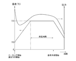
- the vacuum chamber is raised from room temperature T0 (for example, 25 ° C.) to a predetermined temperature T2 (for example, 100 ° C.).
- T0 room temperature
- T2 for example, 100 ° C.
- Warm and bake the vacuum chamber for a predetermined time eg, 4 hours.
- the heating of the vacuum chamber is stopped and naturally cooled, and when the vacuum chamber reaches a predetermined pressure (for example, 1 ⁇ 10 ⁇ 5 Pa) and a predetermined temperature (for example, 30 ° C.), the target is set to a predetermined integrated power. Pre-sputtering to resume production.
- the heating temperature T2 is set in consideration of components having low heat resistance such as an O-ring used in the sputtering apparatus.
- the baking time has been determined from an empirical rule considering the product yield and the like. For this reason, although the amount of gas adsorption on the newly installed deposition prevention plate or the like in the vacuum chamber is different every time, after the maintenance work is completed, the production cannot be resumed unless a predetermined time has passed. There was a bug.
- Patent Document 1 it is known from Patent Document 1 that the vacuum chamber is baked.
- the one disclosed in Patent Document 1 cannot be returned to production unless a predetermined time has elapsed, and a large amount of oxygen gas or inert gas is introduced into the vacuum chamber. There is a problem that becomes high.
- a production return method for a sputtering apparatus includes a preheating step of preheating the vacuum chamber to a first temperature higher than room temperature while the vacuum chamber of the sputtering apparatus is open to the atmosphere. And a baking step in which the vacuum chamber and the target disposed in the vacuum chamber are heated to a second temperature higher than the first temperature and baked while the vacuum chamber is sealed and the inside is evacuated. During the baking process held at the second temperature, the pressure in the vacuum chamber is monitored, and a determination process for determining when the pressure starts to increase and decreases, and the pressure in the vacuum chamber decreases from the increase in the determination process. Immediately after the determination of the point in time, the cooling process for terminating the vacuum chamber baking and forcibly cooling at least the vacuum chamber to a predetermined temperature, And wherein the Mukoto.
- the vacuum chamber is provided with a preheating step of heating the vacuum chamber to the first temperature while the vacuum chamber is open to the atmosphere (that is, during maintenance work). The time until the temperature is raised to the second temperature can be shortened.
- the gas component adsorbed on the newly installed deposition prevention plate or the like in the vacuum chamber is activated, and is discharged into the vacuum atmosphere in the vacuum chamber and discharged.
- the present invention includes the preheating step and the determination of the end of the baking according to the adsorption state of the gas component on the deposition preventing plate or the like, and according to the state in the vacuum chamber. And return to production as soon as possible.
- the gas component remaining on the deposition preventing plate or the like after baking is kept as it is so as not to affect the film formation by sputtering at the time of production return.
- the permanent magnet may be demagnetized by radiant heat from the target. Therefore, the second temperature of the vacuum chamber during baking may be different from the second temperature of the target so that the permanent magnet does not demagnetize.
- the method further includes a pre-sputtering step of introducing a sputtering gas into the vacuum chamber and pre-sputtering the target by supplying power to the target after the cooling step is completed.
- a pre-sputtering step of introducing a sputtering gas into the vacuum chamber and pre-sputtering the target by supplying power to the target after the cooling step is completed.
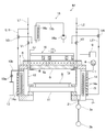
- the sputtering apparatus M is of a magnetron type, for example, and includes a vacuum chamber 1.
- a vacuum exhaust means including a high vacuum pump (for example, a turbo molecular pump) 3 a and a low vacuum pump (for example, a rotary pump) 3 b is connected to the bottom of the vacuum chamber 1 through an exhaust pipe 2.
- the vacuum chamber 1 is provided with a vacuum gauge 4 such as a Pirani vacuum gauge or an ionization vacuum gauge.
- a target 5 is disposed on the upper portion of the vacuum chamber 1.
- the target 5 is manufactured by a known method according to the composition of a thin film to be formed on the surface of the substrate S, such as Cu or Al alloy. During sputtering, the target 5 is bonded to the backing plate 6 and is attached to the vacuum chamber 1 via the insulating plate 7.
- a flow path 6a is formed in the backing plate 6, and a coolant (for example, cooling water) is circulated through the flow path 6a during sputtering so that the target 5 can be cooled.
- the flow path 6 a is connected to a water pipe from a heating medium supply unit, which will be described later, so that the target 5 can be baked by circulating a heating medium (for example, hot water) in the backing plate 6.
- a heating medium for example, hot water
- an earth shield 8 serving as a grounded anode is attached.
- an output from a sputtering power source 9 disposed outside the vacuum chamber 1 is connected.
- a negative DC voltage or a high frequency voltage is applied.
- a magnet unit 10 having a permanent magnet is provided behind the target 5 (upper side opposite to the sputtering surface in FIG. 1), and a closed loop balanced in front of the target 5 (lower side which is the sputtering surface side).
- the tunnel-like magnetic flux is formed, and the electrons ionized in front of the target 5 and the secondary electrons generated by sputtering are captured, so that the electron density in front of the target 5 can be increased and the plasma density can be increased. ing.
- a stage 11 that holds the substrate S at a position facing the target 5 is provided at the bottom of the vacuum chamber 1, and a gas flow that communicates with the gas source 13 and is provided with a mass flow controller 13 a on the side wall of the vacuum chamber 1.
- a tube 13b is connected so that a sputtering gas composed of a rare gas such as Ar or a reactive gas used in reactive sputtering can be introduced into the sputtering chamber 1a at a constant flow rate.
- an adhesion preventing plate 12 that prevents the adhesion of sputtered particles to the wall surface is provided.
- a jacket 14 is provided on the outer wall of the vacuum chamber 1, and the vacuum chamber 1 can be cooled by circulating a refrigerant (cooling water) through a flow path 14 a in the jacket 14.
- a flow path 16b of a heating medium supply unit 16 described later is connected to the flow path 14a, and the vacuum chamber 1 can be baked by circulating a heating medium (hot water) in the jacket 14.
- a heater 15 is embedded in the side wall of the vacuum chamber 1 so that the vacuum chamber 1 can be baked by the heater 15.
- a heating medium supply unit 16 is connected to the cooling water supply path L1 and the cooling water discharge path L2 communicating with the backing plate 6 via three-way valves V1 and V2.
- the heating medium supply unit 16 is also connected to a cooling water supply path L11 branched from the cooling water supply path L1 and a cooling water discharge path L21 joined to the cooling water discharge path L2 via the three-way valves V3 and V4. Yes.
- the heating medium supply unit 16 includes a flow path 16b provided with a circulation pump 16a and a heater 16c that heats cooling water flowing through the flow path 16b. Then, by operating the three-way valves V1 to V4 and operating the circulation pump 16a and the heater 16c, the heating medium (hot water) can be supplied to the backing plate 6 and the jacket 14.
- control means including a computer, a sequencer, a driver, and the like.
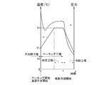
- the heater 15 is operated to preheat the vacuum chamber 1 to a first temperature T1 higher than the room temperature T0 (for example, 50 ° C.) (preliminary). Heating step).
- the first temperature T1 is appropriately set in consideration of the operator performing maintenance work in the vacuum chamber 1.
- the vacuum chamber 1 may be preheated by circulating the heating medium from the heating medium supply unit 16 in the jacket 14.
- the vacuum chamber 1 is sealed, and the vacuum exhaust means 3a and 3b are operated to start evacuation in the vacuum chamber 1.
- the heater 15 raises the vacuum chamber 1 to a second temperature (for example, 100 ° C.) T2 and holds it (baking step).
- a second temperature for example, 100 ° C.
- T2 the second temperature
- the second temperature T2 is appropriately set in consideration of deterioration of the O-ring that is a vacuum seal component.
- the heating medium from the heating medium supply unit 16 is circulated in the backing plate 6, the target 5 is heated to the second temperature, and the target 5 is baked.
- the second temperature of the target 5 is set to a temperature within a range of 60 to 80 ° C. different from the second temperature T2 of the vacuum chamber 1 in consideration of demagnetization of the permanent magnet.
- the temperature of the vacuum chamber 1 and the target 5 is relatively low. It is not activated and is not released into the vacuum chamber 1. For this reason, the pressure in the vacuum chamber 1 decreases. Thereafter, as the temperature of the vacuum chamber 1 and the target 5 rises, the gas component adsorbed in the vacuum chamber 1 is activated and released into the vacuum chamber 1. As a result, the pressure in the vacuum chamber 1 increases.
- the pressure in the vacuum chamber 1 measured by the vacuum gauge 4 is monitored to determine when the pressure has changed from rising to falling (determination step).
- a determination method a known method can be used. For example, the measurement value of the vacuum gauge 4 is sampled every minute, a difference from the previous sampling value is obtained, and the difference is compared with a predetermined reference value. The method is used.
- cooling water for example, 20 ° C.
- cooling water for example, 20 ° C.
- the gas component activated during baking stays on the deposition preventing plate 12 and the like, and is hardly released to the vacuum atmosphere in the vacuum chamber 1.
- the pressure in the vacuum chamber 1 rapidly decreases, and the vacuum chamber 1 is brought to a predetermined pressure (for example, 1 ⁇ 10 ⁇ 5 Pa) and a predetermined temperature (for example, 30 ° C.) suitable for the production return. To reach.
- a predetermined pressure for example, 1 ⁇ 10 ⁇ 5 Pa
- a predetermined temperature for example, 30 ° C.
- a dummy substrate (not shown) that is not used as a product is transferred onto the stage 11 facing the target 5. Then, a negative DC voltage or a high-frequency voltage is applied to the target 5 via the sputtering power source 9 while introducing the sputtering gas from the gas pipe 13b, and pre-sputtering is performed by a predetermined integrated power (pre-sputtering process).
- the pre-sputtering conditions may be set to be the same as or different from the sputtering conditions for the product substrate S.
- the surface of the target 5 is eroded and the gas components adsorbed on the surface of the target 5 are removed, and the gas components remaining on the components such as the deposition preventing plate 12 in the vacuum chamber 1 are covered with the sputtered particles. . For this reason, it is possible to prevent the gas component from being released into the vacuum chamber 1 after the return of production.
- the substrate S of the product is transferred onto the stage 11 facing the target 5 and the film forming process is resumed.
- the vacuum chamber 1 is preheated to the first temperature T1 while the vacuum chamber 1 is opened to the atmosphere, and the baking is performed based on the pressure in the vacuum chamber 1 during baking at the second temperature.
- the production can be restored as soon as possible according to the state of the vacuum chamber 1 after the maintenance work is completed.
- the gas component remaining on the deposition preventive plate 12 and the like is kept as it is after baking, and this gas component is covered with sputtered particles by pre-sputtering, so that the gas component is released into the vacuum chamber after the production return. Can be prevented.
- the running cost can be reduced as compared with a case where a large amount of oxygen gas or inert gas is introduced into the vacuum chamber 1.
- the vacuum chamber 1 is preheated while the vacuum chamber 1 is opened to the atmosphere.
- the target 5 is raised to the second temperature in a short time. May be warm.
- M Sputtering device, 1 ... Vacuum chamber, 5 ... Target.
Landscapes
- Chemical & Material Sciences (AREA)
- Chemical Kinetics & Catalysis (AREA)
- Engineering & Computer Science (AREA)
- Materials Engineering (AREA)
- Mechanical Engineering (AREA)
- Metallurgy (AREA)
- Organic Chemistry (AREA)
- Physical Vapour Deposition (AREA)
Abstract
Description
Claims (2)
- スパッタリング装置の真空チャンバを大気開放している間、この真空チャンバを室温より高い第1の温度に予加熱する予加熱工程と、真空チャンバを密閉してその内部を真空引きしつつ、真空チャンバとこの真空チャンバ内に配置されたターゲットとを第1の温度より高い第2の温度に昇温してベーキングするベーキング工程と、第2の温度に保持したベーキング工程中、真空チャンバ内の圧力を監視し、この圧力が上昇から下降に転じる時点を判定する判定工程と、判定工程にて真空チャンバ内の圧力が上昇から下降に転じる時点が判定された直後に、真空チャンバのベーキングを終了して少なくとも真空チャンバを所定温度まで強制冷却する冷却工程と、を含むことを特徴とするスパッタリング装置の生産復帰方法。
- 前記冷却工程が終了した後、前記真空チャンバ内にスパッタガスを導入すると共に前記ターゲットに電力投入してターゲットをプレスパッタするプレスパッタ工程を更に含むことを特徴とする請求項1記載のスパッタリング装置の生産復帰方法。
Priority Applications (2)
| Application Number | Priority Date | Filing Date | Title |
|---|---|---|---|
| JP2012519206A JP5433786B2 (ja) | 2010-06-10 | 2011-02-03 | スパッタリング装置の生産復帰方法 |
| KR1020127021001A KR101416286B1 (ko) | 2010-06-10 | 2011-02-03 | 스퍼터링 장치의 생산 복귀 방법 |
Applications Claiming Priority (2)
| Application Number | Priority Date | Filing Date | Title |
|---|---|---|---|
| JP2010-132789 | 2010-06-10 | ||
| JP2010132789 | 2010-06-10 |
Publications (1)
| Publication Number | Publication Date |
|---|---|
| WO2011155100A1 true WO2011155100A1 (ja) | 2011-12-15 |
Family
ID=45097722
Family Applications (1)
| Application Number | Title | Priority Date | Filing Date |
|---|---|---|---|
| PCT/JP2011/000603 Ceased WO2011155100A1 (ja) | 2010-06-10 | 2011-02-03 | スパッタリング装置の生産復帰方法 |
Country Status (4)
| Country | Link |
|---|---|
| JP (1) | JP5433786B2 (ja) |
| KR (1) | KR101416286B1 (ja) |
| TW (1) | TW201204853A (ja) |
| WO (1) | WO2011155100A1 (ja) |
Cited By (4)
| Publication number | Priority date | Publication date | Assignee | Title |
|---|---|---|---|---|
| JP2017183558A (ja) * | 2016-03-31 | 2017-10-05 | ルネサスエレクトロニクス株式会社 | 半導体装置の製造方法およびドライエッチング装置のメンテナンス方法 |
| CN113345979A (zh) * | 2021-05-25 | 2021-09-03 | 通威太阳能(成都)有限公司 | 一种真空机台快速复机方法 |
| CN116536625A (zh) * | 2023-04-14 | 2023-08-04 | 福建兆元光电有限公司 | PVD-AlN机台保养后的复机方法 |
| WO2023160809A1 (en) * | 2022-02-25 | 2023-08-31 | Applied Materials, Inc. | Deposition apparatus, substrate processing system and method for processing a substrate |
Families Citing this family (1)
| Publication number | Priority date | Publication date | Assignee | Title |
|---|---|---|---|---|
| CN109295427B (zh) * | 2018-09-29 | 2021-01-22 | 厦门乾照光电股份有限公司 | 一种溅射靶材的清洁方法及装置 |
Citations (3)
| Publication number | Priority date | Publication date | Assignee | Title |
|---|---|---|---|---|
| JPH03236237A (ja) * | 1990-02-14 | 1991-10-22 | Hitachi Ltd | 配線形成方法およびその装置 |
| JP2000038668A (ja) * | 1998-07-22 | 2000-02-08 | Toyobo Co Ltd | 真空薄膜形成装置及び製造方法 |
| JP2010084211A (ja) * | 2008-10-01 | 2010-04-15 | Ulvac Japan Ltd | スパッタリング方法 |
Family Cites Families (1)
| Publication number | Priority date | Publication date | Assignee | Title |
|---|---|---|---|---|
| JPH0246726A (ja) * | 1988-08-09 | 1990-02-16 | Nec Corp | 真空装置の真空度改善方法 |
-
2011
- 2011-02-03 KR KR1020127021001A patent/KR101416286B1/ko active Active
- 2011-02-03 WO PCT/JP2011/000603 patent/WO2011155100A1/ja not_active Ceased
- 2011-02-03 JP JP2012519206A patent/JP5433786B2/ja active Active
- 2011-02-22 TW TW100105795A patent/TW201204853A/zh unknown
Patent Citations (3)
| Publication number | Priority date | Publication date | Assignee | Title |
|---|---|---|---|---|
| JPH03236237A (ja) * | 1990-02-14 | 1991-10-22 | Hitachi Ltd | 配線形成方法およびその装置 |
| JP2000038668A (ja) * | 1998-07-22 | 2000-02-08 | Toyobo Co Ltd | 真空薄膜形成装置及び製造方法 |
| JP2010084211A (ja) * | 2008-10-01 | 2010-04-15 | Ulvac Japan Ltd | スパッタリング方法 |
Cited By (5)
| Publication number | Priority date | Publication date | Assignee | Title |
|---|---|---|---|---|
| JP2017183558A (ja) * | 2016-03-31 | 2017-10-05 | ルネサスエレクトロニクス株式会社 | 半導体装置の製造方法およびドライエッチング装置のメンテナンス方法 |
| CN113345979A (zh) * | 2021-05-25 | 2021-09-03 | 通威太阳能(成都)有限公司 | 一种真空机台快速复机方法 |
| WO2023160809A1 (en) * | 2022-02-25 | 2023-08-31 | Applied Materials, Inc. | Deposition apparatus, substrate processing system and method for processing a substrate |
| CN116536625A (zh) * | 2023-04-14 | 2023-08-04 | 福建兆元光电有限公司 | PVD-AlN机台保养后的复机方法 |
| CN116536625B (zh) * | 2023-04-14 | 2025-12-05 | 福建兆元光电有限公司 | PVD-AlN机台保养后的复机方法 |
Also Published As
| Publication number | Publication date |
|---|---|
| KR101416286B1 (ko) | 2014-07-08 |
| TW201204853A (en) | 2012-02-01 |
| JPWO2011155100A1 (ja) | 2013-08-01 |
| JP5433786B2 (ja) | 2014-03-05 |
| KR20120107011A (ko) | 2012-09-27 |
Similar Documents
| Publication | Publication Date | Title |
|---|---|---|
| US5707498A (en) | Avoiding contamination from induction coil in ionized sputtering | |
| JP5433786B2 (ja) | スパッタリング装置の生産復帰方法 | |
| JP2001023900A (ja) | チャンバのベークアウト及びクールダウン方法 | |
| TWI599669B (zh) | Film forming apparatus and film forming method | |
| TWI713540B (zh) | 濺鍍裝置及其狀態判別方法 | |
| TWI686492B (zh) | 磁控管濺鍍裝置 | |
| JP6640759B2 (ja) | 真空処理装置 | |
| CN109154076B (zh) | 成膜方法和溅射装置 | |
| JP2017166032A (ja) | 成膜装置及び成膜方法 | |
| WO2011131137A1 (zh) | 磁控溅射设备 | |
| JP2014148703A (ja) | スパッタリング装置 | |
| JP2000232068A (ja) | スパッタリング装置 | |
| US20170213706A1 (en) | Rf sputtering apparatus and sputtering method | |
| JP7057442B2 (ja) | 真空処理装置 | |
| TW558738B (en) | Plasma processing | |
| JP2017139164A (ja) | プラズマ処理装置 | |
| JP2001073131A (ja) | 銅薄膜製造方法、及びその方法に用いるスパッタ装置 | |
| JPH1068074A (ja) | スパッタリング方法及び装置 | |
| JP4614252B2 (ja) | 基板処理装置及びこれに用いられるコンピュータプログラム | |
| JP6722466B2 (ja) | 成膜装置及び基板判別方法 | |
| JP3949304B2 (ja) | スパッタリング処理方法と装置 | |
| JP2010084211A (ja) | スパッタリング方法 | |
| CN115802878A (zh) | 一种物理气相沉积方法 | |
| JP6927777B2 (ja) | 成膜方法及びスパッタリング装置 | |
| CN206616268U (zh) | 等离子体增强磁控溅射系统 |
Legal Events
| Date | Code | Title | Description |
|---|---|---|---|
| 121 | Ep: the epo has been informed by wipo that ep was designated in this application |
Ref document number: 11792063 Country of ref document: EP Kind code of ref document: A1 |
|
| WWE | Wipo information: entry into national phase |
Ref document number: 2012519206 Country of ref document: JP |
|
| ENP | Entry into the national phase |
Ref document number: 20127021001 Country of ref document: KR Kind code of ref document: A |
|
| NENP | Non-entry into the national phase |
Ref country code: DE |
|
| 122 | Ep: pct application non-entry in european phase |
Ref document number: 11792063 Country of ref document: EP Kind code of ref document: A1 |