WO2011155030A1 - 走行モデル作成装置及び運転支援装置 - Google Patents
走行モデル作成装置及び運転支援装置 Download PDFInfo
- Publication number
- WO2011155030A1 WO2011155030A1 PCT/JP2010/059715 JP2010059715W WO2011155030A1 WO 2011155030 A1 WO2011155030 A1 WO 2011155030A1 JP 2010059715 W JP2010059715 W JP 2010059715W WO 2011155030 A1 WO2011155030 A1 WO 2011155030A1
- Authority
- WO
- WIPO (PCT)
- Prior art keywords
- driving
- model
- information
- vehicle
- travel
- Prior art date
Links
- 230000008859 change Effects 0.000 abstract description 4
- 238000000034 method Methods 0.000 description 54
- 230000008569 process Effects 0.000 description 45
- 230000001133 acceleration Effects 0.000 description 42
- 238000012545 processing Methods 0.000 description 26
- 238000004891 communication Methods 0.000 description 20
- 230000000694 effects Effects 0.000 description 10
- 238000013459 approach Methods 0.000 description 9
- 230000003287 optical effect Effects 0.000 description 8
- 238000004364 calculation method Methods 0.000 description 4
- 238000010586 diagram Methods 0.000 description 4
- 125000002066 L-histidyl group Chemical group [H]N1C([H])=NC(C([H])([H])[C@](C(=O)[*])([H])N([H])[H])=C1[H] 0.000 description 3
- 230000010365 information processing Effects 0.000 description 3
- 230000005477 standard model Effects 0.000 description 3
- 210000000707 wrist Anatomy 0.000 description 3
- 101000631695 Homo sapiens Succinate dehydrogenase assembly factor 3, mitochondrial Proteins 0.000 description 2
- 102100028996 Succinate dehydrogenase assembly factor 3, mitochondrial Human genes 0.000 description 2
- 238000013500 data storage Methods 0.000 description 2
- 230000003247 decreasing effect Effects 0.000 description 2
- 230000000994 depressogenic effect Effects 0.000 description 2
- 238000013461 design Methods 0.000 description 2
- 238000001514 detection method Methods 0.000 description 2
- 239000000446 fuel Substances 0.000 description 2
- 238000012935 Averaging Methods 0.000 description 1
- 239000000284 extract Substances 0.000 description 1
- 230000006872 improvement Effects 0.000 description 1
- 238000002347 injection Methods 0.000 description 1
- 239000007924 injection Substances 0.000 description 1
- 239000004973 liquid crystal related substance Substances 0.000 description 1
- 230000009467 reduction Effects 0.000 description 1
- 230000004044 response Effects 0.000 description 1
- 238000000926 separation method Methods 0.000 description 1
- 230000007480 spreading Effects 0.000 description 1
Images


Classifications
-
- B—PERFORMING OPERATIONS; TRANSPORTING
- B60—VEHICLES IN GENERAL
- B60W—CONJOINT CONTROL OF VEHICLE SUB-UNITS OF DIFFERENT TYPE OR DIFFERENT FUNCTION; CONTROL SYSTEMS SPECIALLY ADAPTED FOR HYBRID VEHICLES; ROAD VEHICLE DRIVE CONTROL SYSTEMS FOR PURPOSES NOT RELATED TO THE CONTROL OF A PARTICULAR SUB-UNIT
- B60W50/00—Details of control systems for road vehicle drive control not related to the control of a particular sub-unit, e.g. process diagnostic or vehicle driver interfaces
- B60W50/0098—Details of control systems ensuring comfort, safety or stability not otherwise provided for
-
- B—PERFORMING OPERATIONS; TRANSPORTING
- B60—VEHICLES IN GENERAL
- B60W—CONJOINT CONTROL OF VEHICLE SUB-UNITS OF DIFFERENT TYPE OR DIFFERENT FUNCTION; CONTROL SYSTEMS SPECIALLY ADAPTED FOR HYBRID VEHICLES; ROAD VEHICLE DRIVE CONTROL SYSTEMS FOR PURPOSES NOT RELATED TO THE CONTROL OF A PARTICULAR SUB-UNIT
- B60W50/00—Details of control systems for road vehicle drive control not related to the control of a particular sub-unit, e.g. process diagnostic or vehicle driver interfaces
- B60W2050/0062—Adapting control system settings
- B60W2050/0075—Automatic parameter input, automatic initialising or calibrating means
-
- B—PERFORMING OPERATIONS; TRANSPORTING
- B60—VEHICLES IN GENERAL
- B60W—CONJOINT CONTROL OF VEHICLE SUB-UNITS OF DIFFERENT TYPE OR DIFFERENT FUNCTION; CONTROL SYSTEMS SPECIALLY ADAPTED FOR HYBRID VEHICLES; ROAD VEHICLE DRIVE CONTROL SYSTEMS FOR PURPOSES NOT RELATED TO THE CONTROL OF A PARTICULAR SUB-UNIT
- B60W2556/00—Input parameters relating to data
- B60W2556/10—Historical data
-
- B—PERFORMING OPERATIONS; TRANSPORTING
- B60—VEHICLES IN GENERAL
- B60W—CONJOINT CONTROL OF VEHICLE SUB-UNITS OF DIFFERENT TYPE OR DIFFERENT FUNCTION; CONTROL SYSTEMS SPECIALLY ADAPTED FOR HYBRID VEHICLES; ROAD VEHICLE DRIVE CONTROL SYSTEMS FOR PURPOSES NOT RELATED TO THE CONTROL OF A PARTICULAR SUB-UNIT
- B60W30/00—Purposes of road vehicle drive control systems not related to the control of a particular sub-unit, e.g. of systems using conjoint control of vehicle sub-units
- B60W30/18—Propelling the vehicle
- B60W30/18009—Propelling the vehicle related to particular drive situations
- B60W30/18145—Cornering
-
- B—PERFORMING OPERATIONS; TRANSPORTING
- B60—VEHICLES IN GENERAL
- B60W—CONJOINT CONTROL OF VEHICLE SUB-UNITS OF DIFFERENT TYPE OR DIFFERENT FUNCTION; CONTROL SYSTEMS SPECIALLY ADAPTED FOR HYBRID VEHICLES; ROAD VEHICLE DRIVE CONTROL SYSTEMS FOR PURPOSES NOT RELATED TO THE CONTROL OF A PARTICULAR SUB-UNIT
- B60W30/00—Purposes of road vehicle drive control systems not related to the control of a particular sub-unit, e.g. of systems using conjoint control of vehicle sub-units
- B60W30/18—Propelling the vehicle
- B60W30/18009—Propelling the vehicle related to particular drive situations
- B60W30/18154—Approaching an intersection
Definitions
- the present invention relates to a travel model creation device that creates a travel model of a suitable vehicle that is used for driving support that assists the driving operation of a vehicle driver, and a drive support device that performs drive support based on the travel model.
- driving support device that supports the driving operation of the vehicle by the driver by notifying the vehicle driver of information such as the driving environment of the vehicle, such as road conditions.
- driving assistance performed by such a driving assistance device, driving assistance for notifying information and warning regarding a curve ahead is known.
- the driving support for notifying information and warnings related to such curves is not provided appropriately according to the constantly changing driving environment, such support may cause trouble for the driver. . Therefore, conventionally, various techniques for appropriately providing such driving assistance have been proposed.
- the vehicle state at the time of passing through the vehicle front curve is estimated based on the current position of the vehicle, the curve information in front of the vehicle, and the current vehicle state, and stored past curves Among the vehicle states at the time of passing, for example, the vehicle state when the curve is completely bent at the maximum acceleration is set as an allowable vehicle state (running model) when the driver passes the curve.
- the determination as to whether or not to perform driving support on the forward curve is performed based on the allowable vehicle state (travel model) when the driver has passed the past curve. Therefore, it cannot be denied that the suitability of the allowable vehicle state (travel model) when the selected driver passes the curve affects the determination result. That is, if the vehicle state at the time of passing through a curve includes, for example, a vehicle state based on a specific driving state, the specific driving state is selected as an allowable vehicle state (driving model) at the time of passing the driver's curve. If this happens, the above determination may not be made properly. In this way, there is still room for improvement in practice when it comes to driving assistance performed in response to a complex driving environment.
- the present invention has been made in view of such circumstances, and the purpose of the present invention is to create a travel model that is more desirable for practical use, even when a travel model is created based on a travel record. It is an object of the present invention to provide a driving model creation device and a driving support device capable of performing more appropriate driving support based on the driving model.
- the present invention provides a travel model creation device that creates a travel model indicating a travel state of a vehicle, the travel model creation device including road information that is information related to the travel environment of the vehicle, driving The driving model is generated based on driving information that is information related to the driving state of the vehicle that changes due to the driving operation of the driver, and the contribution ratio of the driving information to the generated driving model is “ The gist is to make the “model contribution ratio” variable according to the road information.
- the traveling model is created based on the road information and the driving information whose model contribution rate is variable according to the road information.
- driving information is not reflected or reflected in the driving model to be generated. Even so, it is possible to reduce the degree of influence of driving information by reducing the contribution rate of driving information to the travel model. That is, a travel model can be created as a more appropriate model according to the travel environment of the vehicle. Further, if the travel model created in this way is used for driving support, more suitable driving support can be performed.
- the travel model creation device further includes a model contribution rate of the driving information when the information regarding the road marking on the road surface is not included in the road information, and when the information regarding the road marking is included in the road information. You may comprise so that it may become smaller than the model contribution rate of the said driving information.
- the driver When there is a road marking on the road surface, the driver usually operates the vehicle using the road marking as a guide. For this reason, the traveling state of the vehicle also tends to be stable, and the driving information as information relating to the traveling state also reflects the stable traveling state. Conversely, when there is no road marking on the road surface, the driver performs a driving operation of the vehicle mainly based on his / her own sense. For this reason, the traveling state of the vehicle also tends to be unstable, and the driving information as information relating to the traveling state also reflects the unstable traveling state.
- the travel model when there is no road marking on the road surface, the travel model is created so that the contribution rate, that is, the influence of the driving information on the travel model is reduced. As a result, the accuracy and reliability of the created travel model can be improved. In addition, by using such a highly reliable traveling model for driving support, it becomes possible to perform more preferable driving support.
- the driving model creation device further indicates that the road information indicates that the driving environment has a small degree of freedom of steering operation by the driver, and between the driving model selected as corresponding to the driving environment and the driving information. When the difference is small, the model contribution rate of the driving information may be reduced.
- the degree of freedom of steering operation is small, for example, when the road width is narrow, the driver usually operates the vehicle within a limited steering operation range, so the driving operation of the vehicle tends to be stable. is there. That is, the difference which arises for every driving operation among each driving information as information regarding a driving state is small.
- the driving information model contribution rate is set to “0 (zero)”
- the driving information is not contributed to the creation of the travel model. For this reason, it is possible to reduce the arithmetic processing for creating the travel model. If a travel model based on driving information is not created in the first place, it is possible to reduce the storage area for storing the created travel model.
- the road information may be information regarding an intersection.
- a highly practical travel model for an intersection where the stability or instability of the travel state of the vehicle is likely to fluctuate greatly due to the driving operation of the driver.
- the travel model created for this intersection can be improved in accuracy and reliability. High.
- the model contribution ratio of driving information when the degree of freedom of steering operation by the driver is small to be variable, the accuracy and reliability of the traveling model for the intersection are maintained. Thus, it is possible to reduce the calculation and the like related to the creation of the travel model.
- the present invention provides a driving support device that supports a driving operation of a driver of a vehicle based on a driving model indicating a driving state of the vehicle, and the driving support device includes the model described above.
- the gist is to use a model created by a creation device as the travel model.
- the present invention provides a driving support device that supports driving operation of a driver of a vehicle based on a driving model indicating a driving state of the vehicle, and the driving model includes driving operation of the driver.
- the driving support device generates a “driving model support contribution rate” that is a contribution rate of the driving model to the driving support, based on the driving state changed due to the vehicle.
- the gist is to make it variable based on road information which is information indicating the traveling environment.
- the road model that is, the travel of the vehicle
- the road model is made because the support contribution rate of the travel model depending on the driving operation of the driver is variable based on the road information that is information indicating the travel environment of the vehicle.
- the driving support mode is also changed according to the environment. For this reason, for example, if there is a driving environment in which the driver's burden tends to increase due to the absence of a stop line or an intersection mark, that is, a driving environment where the necessity of driving support is large, the support contribution ratio of the driving model should be increased. In the driving environment where the necessity of driving support is small, it is possible to reduce the support contribution rate of the driving model. As a result, the degree of influence of the driving model in driving assistance can be changed according to the driving environment of the vehicle, and the degree of freedom can be improved even when driving assistance is performed based on the driving model. It becomes like this.
- the driving support device further includes a support contribution rate of the travel model when information regarding road markings on a road surface is not included in the road information, and the information when information regarding the road marking is included in the road information. You may comprise so that it may become small compared with the assistance contribution rate of a driving
- the driver When there is a road marking on the road surface, the driver usually operates the vehicle with the road marking as a guide. For this reason, the traveling state of the vehicle also tends to be stable, and the traveling model indicating the traveling state of the vehicle is created based on the driving operation of the driver, so that the stable traveling state is reflected. Conversely, when there is no road marking on the road surface, the driver performs the driving operation of the vehicle mainly based on his / her own sense. For this reason, the traveling state of the vehicle also tends to be unstable, and the traveling model indicating the traveling state of the vehicle is created based on the driving operation of the driver, and thus the unstable traveling state is reflected.
- driving support when there is no road marking on the road surface, driving support is performed so that the support contribution rate of the travel model is reduced, that is, the influence is reduced. As a result, the stability of driving support can be improved and more suitable driving support can be performed.
- the driving support device may be further configured to perform the driving support based on a standard travel model prepared in advance when information regarding road markings on the road surface is not included in the road information.
- driving support with predetermined stability is performed by performing driving support based on a standard driving model prepared in advance. For this reason, the stability of driving support is maintained well.
- the driving support device further indicates the support contribution rate of the driving model when the road information indicates that the driving environment has a low degree of freedom of steering operation by a driver in a driving environment with a high degree of freedom of steering operation. You may comprise so that it may become small compared with the assistance contribution rate of the said travel model when showing that there exists.
- the degree of freedom of the steering operation when the degree of freedom of the steering operation is small, for example, the road width is narrow, the driver usually performs the driving operation of the vehicle within a limited steering operation range. For this reason, since the driving operation of the vehicle tends to be stable, the difference that occurs in the traveling state of the vehicle for each driving operation is small. Conversely, when the degree of freedom of steering operation is large, such as when the road is wide, the driver can freely drive the vehicle in a wide steering operation range. For this reason, since the traveling state of the vehicle also tends to be unstable, there is a high possibility that a large difference occurs in the traveling state of the vehicle for each driving operation.
- the driving support is performed so that the influence of the driving model at that time, that is, the influence of the driving model is reduced.
- driving assistance is performed in a manner that does not make the driver feel bothersome. That is, suitable driving assistance is provided to the driver.
- the driving support device is further configured to perform the driving support based on a standard driving model prepared in advance when the road information indicates that the driving environment has a low degree of freedom of steering operation by the driver. May be.
- the road information may be information regarding an intersection. According to such a configuration, among various types of road information, a traveling model that depends on the driving operation of the driver, even at an intersection where the stability of the driving state of the vehicle is likely to fluctuate greatly due to the driving operation of the driver.
- the driving support based on can be suitably provided.
- FIG. 1 is a block diagram showing a system configuration of a first embodiment that embodies a driving support apparatus according to the present invention.
- the top view which shows typically the map information containing the some intersection used with the apparatus of the embodiment.
- the top view which shows the example of the 1st intersection where learning of a driving
- FIG. 5B is a diagram illustrating a list that illustrates a normative travel model for the intersection
- FIG. 5C is a diagram illustrating a list that illustrates a typical travel model for the intersection
- D is a figure which shows the list
- the flowchart which shows the process sequence which learns a driving
- wrist which illustrates the aspect in which the driving
- the flowchart which shows the process sequence of the driving assistance performed based on a driving
- the flowchart which shows the driving assistance processing procedure of 2nd Embodiment which actualized the driving assistance apparatus concerning this invention.
- (A) is a top view of the 3rd intersection which illustrates the aspect of a steering freedom degree
- (b) is a top view of the 4th intersection which illustrates the aspect of a steering freedom degree.
- the flowchart which shows the process sequence of the deceleration assistance in the said driving assistance.
- the top view which illustrates the 5th intersection where driving assistance is performed in the 3rd embodiment which materialized the driving support device concerning the present invention.
- 4 is a flowchart showing a processing procedure for determining the degree of steering freedom in the embodiment.
- the flowchart which shows the process sequence of the driving assistance of other embodiment which actualized the driving assistance apparatus concerning this invention.
- FIG. 1 is a diagram illustrating the configuration of the driving support apparatus using blocks.
- the vehicle 10 is provided with a driving support control computer (driving support ECU) 11 that performs various controls for supporting the driving operation of the driver driving the vehicle 10.
- the driving support ECU 11 includes a microcomputer that includes a CPU that executes various arithmetic processes, a ROM that stores various control programs, a RAM that is used as a work area for data storage and program execution, an input / output interface, a memory, and the like. It is structured in the center.
- the driving support ECU 11 is provided with a driving information processing unit 110, a personal travel model creation processing unit 111, and a driving support execution unit 112.
- the driving information processing unit 110 performs processing for temporarily storing driving information including information such as speed and acceleration indicating the traveling state detected as the vehicle 10 travels.
- the personal travel model creation processing unit 111 is a travel model used for driving assistance, and is a travel model created based on learning the travel state of the vehicle according to the driving operation of the driver. Execute the creation process.
- the personal travel model creation processing unit 111 selects whether to use the travel state of the vehicle for learning, and learns the travel state of the vehicle selected for learning by a known learning method and reflects it in the personal travel model.
- the personal travel model is created through the learning process.
- the driving support execution unit 112 executes various types of control related to driving support, particularly right turn support that is performed when the vehicle 10 makes a right turn at an intersection.
- Driving assistance includes various modes such as information provision and warning performed through sound, sound, images, etc., braking control such as preliminary braking and assist braking. From this, driving assistance according to one or a plurality of modes selected from these modes is executed.
- the driving support ECU 11 temporarily stores driving information, performs personal driving model creation processing, executes driving support, and various parameters used for arithmetic processing of the various programs. Etc. are stored in advance.
- the driving assistance ECU 11 includes a brake control computer (brake ECU) 12 for controlling the brake of the vehicle 10 and an engine control computer (engine ECU) 13 for controlling the engine of the vehicle 10, and a control area network CAN (Control Area Network). ) And the like are connected to each other via an in-vehicle network.
- a steering control computer (steering ECU) 14 that controls steering of the vehicle 10 and the like is also communicably connected via an in-vehicle network such as CAN.
- Each of the ECUs 12 to 14, like the driving support ECU 11, has a CPU for executing various arithmetic processes, a ROM for storing various control programs, a RAM used as a work area for data storage and program execution, A microcomputer including an output interface and a memory is mainly configured.
- the brake ECU 12 is an ECU that controls the brake device of the vehicle 10 and is connected to various sensors such as the vehicle speed sensor 40 and the brake sensor 43 and controls the brake device of the vehicle 10 based on signals from the various sensors. Through the control, the vehicle 10 is caused to generate a braking force. Specifically, the brake device is controlled by calculating the required braking force based on the speed of the vehicle 10 grasped based on the signal from the vehicle speed sensor 40, the brake depression amount signal of the brake sensor 43, and the like. To do. In the present embodiment, the brake ECU 12 performs braking control for supporting deceleration or stop of the vehicle 10 based on the deceleration assistance signal for driving assistance transmitted from the driving assistance ECU 11, for example, preliminary braking or assist braking. The control which performs is also performed.
- the engine ECU 13 is an ECU that controls the operation of the engine of the vehicle 10 and is connected to an accelerator sensor 44 that detects an accelerator depression amount, a sensor that detects an intake air amount, a throttle valve drive circuit, a fuel injection
- the drive circuit of various apparatuses, such as a drive circuit of a valve, is connected.
- engine ECU13 outputs the command signal of the drive circuit of the said various apparatuses while detecting the driving
- engine operation control is performed through the engine ECU 13.
- the steering ECU 14 is an ECU that controls the steering of the vehicle 10, and is connected to various sensors such as the gyro sensor 42 and the steering angle sensor 45, and is steered by electric assist control based on signals from the various sensors. Control.
- the car navigation system 20 and a database 21 that stores various information such as road map information and driving models in a readable / writable manner are connected to the driving assistance ECU 11 via a vehicle-mounted network such as CAN.
- the car navigation system 20 detects the current position of the vehicle using a global positioning system (GPS) or the like, and refers to road map information stored in advance so that the driver can reach the driving destination. The travel route of the vehicle 10 is guided.
- the car navigation 20 is provided with a display device, an input device, and an audio device (not shown).
- the display device is composed of a liquid crystal display, for example, and is installed near the center console in the passenger compartment. On this display device, an image corresponding to image data input from the car navigation system 20 is displayed. Thus, for example, the car navigation system 20 outputs image data that combines the current position of the vehicle 10 and a map around the vehicle 10, thereby displaying an image that combines the position of the vehicle 10 and the map around it on the display device. Display.
- the display device includes image data such as map display image data and a warning display corresponding to information (driving support signal) input from the driving support ECU 11 to alert the driver. Data is also entered.
- the input device is, for example, a touch switch or a mechanical switch integrated with the display device, and is used for various input operations.
- a driver can be set in the driving support ECU 11 via the input / output device.
- a standard travel model adopted instead of the individual travel model can be selected and set from a plurality of travel models.
- the sound device is a device that generates sound and sound, and outputs sound and sound corresponding to sound and sound data input from the car navigation system 20.
- Voice information such as route guidance and traffic information, voice information corresponding to information from the driving support ECU 11, and the like are input from the car navigation system 20 as sound / voice data.
- the car navigation system 20 of the present embodiment acquires and uses road map information stored in advance in the database 21.
- the car navigation 20 transmits position information related to the position of the vehicle 10, road map information extracted as information around the current position, and the like to the driving assistance ECU 11.
- the database 21 is a device that stores various information such as road map information (map database) used for navigation processing and various travel models, and a HDD (Hard Disk Drive) that is a nonvolatile storage device is used as the storage device. .
- road map information map database
- HDD Hard Disk Drive
- the road map information is information related to the map, and is composed of data for displaying the background of the road and the road map, data composed of intersection names, and the like. Further, the road map information includes road ancillary information such as road shape, information on intersections and crosswalks on the road.
- the road ancillary information includes intersection data, which is data for the intersection.
- the intersection data includes information such as position, presence of traffic lights, stop line position, road shape of the intersecting road, pedestrian crossing, and road markings on the road surface. Is included.
- road map information for example, road map information that is a traveling environment including intersections C1 to C6 and intersection data related to the intersections shown in FIG. 2 are stored.
- the first intersection C1 has a structure in which two roads, a first road R1 extending in the vertical direction in FIG. 4 and a second road R2 extending in the left-right direction in FIG. 4, intersect. ing.
- the first vertical road R1 in the vertical direction is provided with a first vertical travel zone that extends from the top to the bottom and a second vertical travel zone that consists of one lane La1 that extends from the bottom to the top.
- R2 is provided with a first left and right traveling zone that extends from right to left and a second left and right traveling zone that has two lanes Ls1 and Ls2 that extend from left to right.
- the second left and right traveling zone has a shoulder lane Ls1 and a center lane Ls2.
- a plurality of road markings are provided at the first intersection C1. That is, an intersection mark 51 is provided at the center of the first intersection C1, and a right turn auxiliary line 52 is provided from the lane La1 of the first road R1 toward the two lanes Ls1 and Ls2 of the second road R2. Yes.
- a lane La1 of the first road R1 is provided with a center line 53 and a stop line 54, and a pedestrian crossing 55, a center line (solid line) 56, and the lanes Ls1, Ls2 are provided on the second road R2.
- a lane boundary line 57 that separates the two from each other is provided.
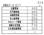
- intersection data 51A is set for the first intersection C1 having the above structure.
- the intersection data 51A includes position information A10 for specifying the position of the first intersection C1 on the map, traffic signal information B10 indicating the presence or absence of traffic lights, lane information C10 indicating the number of lanes of each road R1, R2, and the like. Stop line information D10 indicating the position of the stop line 54 and the like is set.
- the intersection data 51A includes center mark information E10 indicating the presence / absence of the intersection mark 51 at the intersection, pedestrian crossing information F10 indicating the presence / absence of the pedestrian crossing 55, and right turn auxiliary line information G10 indicating the presence / absence of the right turn auxiliary line 52. Is set. Further, in the intersection data 51A, the presence or absence of the center line 53 (56) and the lane boundary line 57 on each road R1, R2 may be set.
- the road map information transmitted from the car navigation system 20 to the driving support ECU 11 also includes the above-described road accessory information and the like.
- an intersection list 50 is associated with the road map information.
- the intersection list 50 is for associating intersection classifications and travel models with the intersections.
- intersections C1 to C6 are associated with intersection classifications, personal travel models, and the like.
- the intersection classification indicates a classification classified according to the possibility of driving support by the same traveling model. That is, in the intersection classification, values are given to classify the intersections by shape, structure, etc., and the same values are given to intersections having similar shapes, structures, etc.
- intersections having the same intersection classification value can perform driving support based on the same travel model.
- the personal travel model is data that can be used as a reference for the travel state of the vehicle 10 during driving assistance, and is provided for each of the intersections C1 to C6 as the travel environment.
- the first intersection C1 is associated with the intersection classification value CT1 and the individual travel model MC1.
- the intersection classification value CT2 and the individual travel model MC2 are present
- the intersection classification value CT1 and the individual travel model MC3 are present
- the fourth intersection C4 is associated with each other.
- the fifth intersection C5 is associated with the intersection classification value CT3 and the individual traveling model MC5
- the sixth intersection C6 is associated with the intersection classification value CT1 and the individual traveling model MC6.
- the database 21 is provided with a driving information storage unit 210 and a travel model storage unit 211.
- the driving information storage unit 210 is for temporarily storing driving information including values detected while the vehicle 10 is traveling.
- the traveling model storage unit 211 is for storing various traveling models used for driving support.
- the traveling model has data corresponding to driving information determined according to the traveling environment.
- the traveling state includes factors such as the speed, acceleration / deceleration, steering angle, and position of the vehicle 10.
- the driving information includes the values of the above-described elements included in the running state as time series data.
- the driving assistance ECU 11 can select the driving model corresponding to the driving environment that is the target of driving assistance, and can implement driving assistance based on the driving information included in the selected driving model. Yes.
- the norm A travel model MCs (FIG. 6B), a general travel model MCu (FIG. 6C), and a calculated travel model MCx (FIG. 6D) are provided.
- the normative travel model MCs, the general travel model MCu, and the calculated travel model MCx have the same items as the individual travel model MC1.
- the personal travel model MC1 is a travel model created for each driver, and is a travel model in which the driving information of the target driver is learned by a known learning method.
- the reference traveling model MCs is a traveling model prepared in advance, and is a traveling model created from driving information based on an exemplary driving operation by a driver such as a professional driver.
- the general travel model MCu is a travel model prepared in advance, and is a travel model created by averaging a large number of driving information obtained from a large number of general driving operations acquired in advance. is there.
- the calculated travel model MCx is a travel model prepared in advance, and is a travel model calculated by a predetermined calculation performed based on data indicating the road structure and the like of the travel environment.
- the travel model includes a deceleration start position that is a position where the vehicle 10 starts to decelerate to turn right, a deceleration end position that ends the deceleration, an acceleration start position that starts acceleration for the right turn, and an acceleration that ends the acceleration. It has an end position.
- the traveling model has a steer turning start position at which the steering is turned to the right for a right turn, a steer returning start position at which the steering turned to the right is returned, and a steering return end position at which the steering is finished.
- the travel model is an average value of deceleration (deceleration acceleration) at the time of right turn, an average value of acceleration at the time of right turn, an average value of lateral G (lateral acceleration) at the time of right turn, and a speed when approaching an intersection. Has approach speed.
- AC21, steer cut start position ST11, steer return start position ST21, and steer return end position ST31 are set.
- an average DA1 of deceleration, an average AA1 of acceleration, an average CA1 of lateral acceleration, and an approach speed SP1 are set.
- the subscript is “s”
- the deceleration start position DC1s, the deceleration end position DC2s, and the acceleration start are values corresponding to the items set in the travel model.
- a position AC1s, an acceleration end position AC2s, a steer cut start position ST1s, a steer return start position ST2s, and a steer return end position ST3s are set.
- the average deceleration DAs, the average acceleration AAs, the average lateral acceleration CAs, and the approach speed SPs are set.
- the subscript “u” is used, and the deceleration start position DC1u, the deceleration end position DC2u, and the acceleration start are set as values corresponding to the items set in the travel model.
- a position AC1u, an acceleration end position AC2u, a steer cut start position ST1u, a steer return start position ST2u, and a steer return end position ST3u are set.
- an average deceleration DAU, an average acceleration AAu, an average lateral acceleration CAu, and an approach speed SPu are set.
- the subscript is “x”
- the deceleration start position DC1x, the deceleration end position DC2x, and the acceleration start are values corresponding to the items set in the travel model.
- a position AC1x, an acceleration end position AC2x, a steer cut start position ST1x, a steer return start position ST2x, and a steer return end position ST3x are set.
- the average deceleration DAx, the average acceleration AAx, the average lateral acceleration CAx, and the approach speed SPx are set.
- the road map information transmitted from the car navigation system 20 to the driving support ECU 11 includes the above-described various traveling models.
- the driving support ECU 11 is electrically connected to an output device (man machine interface), for example, a speaker 25, for outputting various types of information such as warnings related to driving support.
- This output device is a device that generates a warning sound for alerting the driver based on a warning related to driving support, and outputs a warning sound corresponding to a signal from the driving support ECU 11. Note that the output device is not limited to the above-described speaker.
- the driving support ECU 11 is electrically connected to various information acquisition devices such as an inter-vehicle communication device 30, an infrastructure communication device 31, a global positioning system (GPS) 32, an in-vehicle camera 33, and an in-vehicle radar 34. Yes.
- various information acquisition devices such as an inter-vehicle communication device 30, an infrastructure communication device 31, a global positioning system (GPS) 32, an in-vehicle camera 33, and an in-vehicle radar 34.
- the vehicle-to-vehicle communication device 30 is a communication device that performs so-called vehicle-to-vehicle communication in which various types of information such as vehicle position information and travel information are transmitted to and from other vehicles located around the vehicle 10 by wireless communication. .
- vehicle information is periodically exchanged with each of a plurality of vehicles in the communicable area.
- the infrastructure communication device 31 is a communication device that communicates with an optical beacon device (not shown) provided on a road by an optical signal such as an infrared signal. And the infrastructure communication apparatus 31 transmits the received infrastructure information signal to driving assistance ECU11 while receiving the infrastructure information signal transmitted from an optical beacon apparatus. As a result, the driving assistance ECU 11 can grasp the infrastructure information.
- the infrastructure communication device 31 receives road traffic information distributed from a VICS (Vehicle Information and Communication System) center as infrastructure information via the optical beacon device.
- the infrastructure information is detected by accompanying information associated with this road, such as road conditions (including intersection shape, curvature, gradient, and number of lanes) of the surrounding road where the optical beacon device is provided, and ground facilities.
- information on moving bodies of other vehicles in the vicinity is also included.
- the infrastructure information may include intersection data notified from an intersection control device that can notify the outside of the information. That is, the driving support ECU 11 may acquire intersection data via the infrastructure communication device 31.
- the GPS 32 receives a GPS satellite signal to detect the absolute position of the vehicle 10 and detects the position of the vehicle 10 based on the received GPS satellite signal. Further, the GPS 32 transmits the detected position information of the vehicle 10 to the driving support ECU 11. Thereby, the driving assistance ECU 11 can grasp the position of the vehicle 10.
- the in-vehicle camera 33 images a predetermined range in front of the vehicle 10 with an optical CCD camera or the like installed on the back side of the rearview mirror, and transmits an image signal based on the captured image to the driving support ECU 11.
- the driving support ECU 11 extracts a front signal state (signal color, etc.) and a front road sign (stop line, center line, etc.) based on the image signal captured by the in-vehicle camera 33. And driving assistance of the vehicle 10 can be performed based on the extracted front signal state and the front road marking.
- the in-vehicle radar 34 detects a distance, a relative speed, an azimuth, and the like with a reflecting object such as a forward vehicle that reflects the laser light using the laser light. These detection results are transmitted to the driving assistance ECU 11 for each reflecting object. As a result, the driving assistance ECU 11 can determine the presence or type of a moving body or an obstacle such as another vehicle in front of the vehicle 10 and can grasp the separation distance.
- various sensors such as a vehicle speed sensor 40, an acceleration sensor 41, a gyro sensor 42, a brake sensor 43, an accelerator sensor 44, and a steering angle sensor 45 are electrically connected to the driving support ECU 11.
- the vehicle speed sensor 40 detects the rotational speed of the wheel and transmits a signal corresponding to the detected rotational speed to the driving assistance ECU 11.
- the acceleration sensor 41 detects the acceleration of the vehicle and transmits a signal corresponding to the detected acceleration to the driving support ECU 11.
- the gyro sensor 42 detects the vehicle traveling direction, and transmits a signal corresponding to the detected traveling direction to the driving assistance ECU 11.
- the brake sensor 43 detects whether or not the driver has operated the brake pedal and the amount of depression of the pedal, and transmits a signal corresponding to the presence or absence of the detected operation and the amount of depression to the driving support ECU 11.
- the accelerator sensor 44 detects whether or not the driver has operated the accelerator pedal and the amount of pedal depression, and transmits a signal corresponding to the presence or absence of the detected operation and the amount of pedal depression to the driving support ECU 11.
- the steering angle sensor 45 calculates a steering angle based on the detected amount of change in the steering angle of the steering, and transmits a signal corresponding to the calculated steering angle to the driving support ECU 11. Since various signals from the respective sensors are transmitted to the driving assistance ECU 11 at predetermined intervals, the driving assistance ECU 11 determines the vehicle such as the position, speed, direction, etc. of the vehicle 10 based on the various signals transmitted. The situation can be grasped sequentially.
- FIG. 7 is a flowchart showing a procedure for creating a personal travel model
- FIG. 8 is a list showing an example of the created personal travel model.
- the personal travel model creation process is appropriately performed when traveling in a travel environment, for example, each of the intersections C1 to C6, based on the road map information and the current position of the vehicle 10, and the like.
- the following describes the personal travel model creation processing for the first intersection C1, and does not describe the personal travel model creation processing for the other intersections C2 to C6.
- the created individual travel model is a model that naturally matches the driving characteristics of each driver.
- the process of creating a personal travel model corresponding to one driver will be described, and for the convenience of explanation, the description of the personal travel model creation form corresponding to other drivers will be omitted.
- the driving support ECU 11 starts storing driving information of the vehicle 10 (step S10 in FIG. 7). That is, the driving information is temporarily stored in time series in the memory of the driving support ECU 11 or the driving information storage unit 210 of the database 21. Then, the driving assistance ECU 11 determines whether or not the vehicle 10 makes a right turn at the first intersection C1 (step S11 in FIG. 7).
- Judgment that the vehicle 10 makes a right turn at the first intersection C1 is that the route guidance of the car navigation 20 is a right turn, that the direction indicator indicates a right turn, a route that normally turns right, It is determined from the fact that deceleration has started in an unnecessary driving environment and that the manner of driving operation of the driver is similar to a standard model at the time of a right turn operation. Note that the traveling environment that does not require deceleration is determined based on the in-vehicle camera 33, the in-vehicle radar 34, infrastructure information, road map information, and various types of information acquired by inter-vehicle communication.
- the driving environment that needs to be decelerated is, for example, that the yellow signal or red signal is lit, that it is a temporary stop intersection, that the vehicle ahead has decelerated, It is judged from the fact that the inter-vehicle distance has become shorter.
- the driving assistance ECU 11 ends the recording of the traveling state and discards the recorded traveling state (FIG. 7). Step S13), the personal travel model creation process is terminated.
- the driving assistance ECU 11 determines whether or not there is an intersection mark 51 that is a road sign at the first intersection C1. (Step S12 in FIG. 7). Whether there is an intersection mark 51 at the first intersection C1 is determined based on various information acquired from the in-vehicle camera 33, infrastructure information, and road map information. When it is determined that there is no intersection mark 51 at the first intersection C1 (NO in step S12 in FIG. 7), the driving assistance ECU 11 ends the recording of the traveling state and discards the recorded traveling state (in FIG. 7). Step S13), the personal travel model creation process is terminated.
- the driving assistance ECU 11 determines whether the vehicle 10 has left the intersection (step S14 in FIG. 7). . Whether the vehicle 10 has left the intersection is determined by comparing the position of the vehicle 10 with the position of the first intersection C1 based on road map information and infrastructure information, the steering angle of the steering of the vehicle 10, This is performed based on speed, recognition by the in-vehicle camera 33, and the like. When it is determined that the vehicle 10 has not left the intersection (NO in step S14 in FIG. 7), the driving support ECU 11 periodically determines whether the vehicle 10 has left the intersection (step S14 in FIG. 7). Repeat.
- the driving assistance ECU 11 ends the recording of the traveling state of the vehicle 10 (step S15 in FIG. 7), and the individual traveling.
- the model is learned (step S16 in FIG. 7).
- the learning of the personal travel model is performed based on the recorded driving information of the vehicle 10.
- Driving information of the vehicle 10 is reflected in each item of the personal travel model MC1 (FIG. 6A) by learning the personal travel model.
- the result of this learning is reflected in the individual driving model MC1 before learning, and the value of each item is set to the value shown in each item of the individual driving model MC1a after learning, for example, as shown in FIG. Is done.
- the values of the individual travel model MC1 values are as follows: the deceleration start position DC11 is the deceleration start position DC11a, the deceleration end position DC21 is the deceleration end position DC21a, and the acceleration start position AC11 is the acceleration start position AC11a.
- the acceleration end position AC21 is set as the acceleration end position AC21a.
- the steer cut start position ST11 is set to the steer cut start position ST11a
- the steer return start position ST21 is set to the steer return start position ST21a
- the steer return end position ST31 is set to the steer return end position ST31a.
- the average deceleration DA1 is set as the average deceleration DA1a
- the average acceleration AA1 is set as the average acceleration AA1a
- the average lateral acceleration CA1 is set as the average lateral acceleration CA1a
- the approach speed SP1 is set as the approach speed SP1a. Is done.
- FIG. 9 is a plan view showing the second intersection C2.
- FIG. 10 is a flowchart showing a driving assistance procedure.
- driving assistance is appropriately performed when traveling in a driving environment subject to driving assistance based on road map information and the current position of the vehicle 10, that is, when the vehicle 10 travels in a traveling environment for which a traveling model is prepared.
- the vehicle 10 turns right at the first intersection C1 shown in FIG. 4 as an example of an intersection having an intersection mark from the lane La1 to the central lane Ls2 like the first trajectory Tr1, and at the intersection mark A second intersection C2 shown in FIG. 9 as an example of an intersection that does not have a right turn from the first road La11 to the second road Ls11 as shown by the second trajectory Tr2.
- the driving assistance ECU 11 determines whether or not the vehicle 10 makes a right turn at the intersection (step S20 in FIG. 10).
- the determination that the vehicle 10 turns right at the intersection is determined in the same manner as in step S11 in FIG. That is, the route guidance of the car navigation 20 is a right turn, the direction indicator indicates a right turn, a route that usually makes a right turn, a deceleration started in a driving environment that does not require deceleration, This is determined from the fact that the mode of the driving operation of the driver is similar to a standard model at the time of normal right turn operation. If it is determined that the intersection does not turn right (NO in step S20 in FIG. 10), the driving assistance ECU 11 ends the driving assistance.
- the driving assistance ECU 11 determines whether or not there is an intersection mark (51) at the intersection (step S21 in FIG. 10). Whether there is an intersection mark (51) at the intersection is determined in the same manner as in step S12 of FIG. 7, and is determined based on various information acquired from the in-vehicle camera 33, infrastructure information, and road map information. When it is determined that the intersection mark 51 is present at the intersection because the traveling environment is the first intersection C1 or the like (YES in step S21 in FIG. 10), the driving assistance ECU 11 ends the driving assistance.
- step S21 in FIG. 10 the driving assistance ECU 11 moves to the second intersection C2. It is determined whether or not the corresponding individual travel model MC2 has been learned (step S22 in FIG. 10). Whether or not the personal travel model MC2 has been learned is determined by whether or not the personal travel model corresponding to the travel environment is held in the database 21.
- the driving support ECU 11 uses the personal travel model MC2 that is a driver-specific travel model as a travel model for driving support. (Step S23 in FIG. 10).
- the driving assistance ECU 11 provides a general travel model (a travel model prepared in advance as a travel model that can be used in the travel environment).
- MCu is a standard travel model, and this standard travel model is determined as a travel model used for driving support (step S24 in FIG. 10).
- normative driving models (MCs) and calculated driving models (MCx) are also prepared in advance, so that the standard driving model (MCu) can be changed to the standard driving model (MCu) by the standard driving model selection setting through the car navigation system 20.
- these travel models can be standard travel models.
- the driving support ECU 11 determines whether or not a right turn control support start condition is satisfied (step S25 in FIG. 10).
- the right turn control support start condition can be determined by determining that a predetermined time has elapsed since the start of driving support, that the speed of the vehicle 10 has fallen below a certain value, that the accelerator is not depressed, Each condition such as that the distance to the intersection C2 has become a certain value or less is used. That is, it is determined that the right turn control support start condition is satisfied when one or more conditions adopted from the above-described conditions are satisfied.
- step S26 in FIG. 10 the driving support ECU 11 performs right turn control support (step S26 in FIG. 10).
- the driving support ECU 11 determines whether or not the right turn control support end condition is satisfied (step S27 in FIG. 10).
- step S27 in FIG. 10 the driving support ECU 11 does not perform the right turn control support and the right turn control support end condition is satisfied. It is determined whether or not (step S27 in FIG. 10).
- Whether or not the right turn control support termination condition is satisfied is determined on the condition that the vehicle exits the second intersection C2, depresses the accelerator more than a predetermined value, or the speed of the vehicle 10 exceeds a predetermined value. The That is, it is determined that the right turn control support end condition is satisfied when one or more conditions adopted from the above-described conditions are satisfied.
- step S27 in FIG. 10 when it is determined that the right turn control support end condition is not satisfied (NO in step S27 in FIG. 10), the driving support ECU 11 returns to step S25 in FIG. 10 and starts the right turn control support. It is determined whether the condition is satisfied, and the subsequent processing is repeated. On the other hand, when it is determined that the right turn control support end condition is satisfied (NO in step S27 in FIG. 10), the driving support ECU 11 ends the driving support.
- the driving support device creates a personal travel model based on the intersection data and driving information (the learning result is reflected), but there is no intersection mark 51.
- the personal driving model is not created (not learned) based on driving information. That is, the “driving information model contribution ratio”, which is the contribution ratio of the driving information to the creation of the personal driving model, is changed according to the intersection data. For example, when there is an intersection mark 51, “model contribution ratio of driving information” is 100%, and when there is no intersection mark 51, “model contribution ratio of driving information” is 0%.
- driving information driving information when there is no intersection mark 51
- driving information driving information when there is no intersection mark 51
- driving environment that is determined to be unsuitable for the creation of a personal driving model due to large variations in the driving operation of the driver, etc. It is possible not to reflect in the traveling model. That is, a personal travel model can be created as a more appropriate model according to the travel environment of the vehicle. Further, if the personal travel model created in this way is used for driving assistance, more suitable driving assistance can be performed.
- a high individual driving model is suitably created. For example, when the information about the intersection mark 51 is not included in the intersection data, the contribution of the driving information to the personal driving model is eliminated (the model contribution rate of the driving information is reduced), thereby the second intersection C2.
- the personal travel model created for the model is highly accurate and reliable.
- the travel model created in this way is used for intersections, it is possible to perform suitable driving support in accordance with the traveling environment for each intersection.
- the “driving model support contribution rate” that is a contribution rate to the driving support of the individual driving model depending on the driving operation of the driver is variable. It is said. For this reason, according to road map information, ie, the traveling environment of the vehicle 10, the mode of driving assistance is also changed.
- the traveling environment in which the driver's burden tends to be large due to the absence of the stop line 54 or the intersection mark 51 that is, a traveling environment in which the necessity of driving assistance is large (for example, the second intersection C2)
- the traveling It becomes possible to increase the support contribution ratio of the model, and in the driving environment (for example, the first intersection C1) where the necessity of driving support is small, the support contribution ratio of the driving model is reduced. It is also possible.
- the influence degree of the driving model in driving assistance can be changed. For this reason, even when driving assistance is performed based on the travel model, the degree of freedom can be improved.
- a travel model used for driving support is selected based on the presence or absence of a personal travel model that is suitably created (learned), that is, the personal travel model Change the support contribution rate.
- a standard travel model is used for driving support, that is, the contribution of the personal travel model is eliminated.
- intersection mark 51 If there is no road marking at the intersection (intersection mark 51), driving assistance is performed based on a standard driving model prepared in advance, so that predetermined stable driving assistance is performed. The stability of is maintained well.
- FIGS. 1-10 A second embodiment of the driving support device according to the present invention will be described with reference to FIGS.
- the driving support device of the present embodiment is different from the previous first embodiment in the processing procedure for personal travel model creation processing and driving support, but the other configurations are the same. Differences will be mainly described, and for convenience of description, the same reference numerals will be assigned to the same components and the description thereof will be omitted.
- FIG. 11 is a flowchart showing a driving assistance processing procedure according to this embodiment.
- FIG. 12 is a flowchart showing a determination process of the degree of steering freedom in driving support.
- driving assistance a deceleration assistance for a right turn will be described as an example.
- the vehicle 10 turns right at the first intersection C1 and the fourth intersection C4 shown in FIG. 13B as an example of an intersection having a small steering degree of freedom. Further, the vehicle 10 turns right at a third intersection C3 shown in FIG. 13A from the first road La12 toward the second road Ls12 as a third trajectory Tr3 as an example of an intersection with a high degree of steering freedom.
- the third intersection C3 has an arcuate shape with rounded corners at the four corners 60a to 60c of the intersection.
- the road width from the center of the third intersection C3 to the corner 60d is a right angle. Compared to such a case, it is spreading. For this reason, the degree of freedom of the third trajectory Tr3 that can be taken when the vehicle 10 makes a right turn is large. That is, in this case, the range of selection of the driving operation by the driver is widened, that is, the degree of freedom of steering is large.
- the fourth intersection C4 may occur when the approach destination is restricted to the shoulder lane Ls13 or the center lane Ls14 of the second road. . That is, when the fourth trajectory Tr4 that can be taken when making a right turn at the fourth intersection C4 is naturally limited, the degree of freedom of steering becomes small, but when the lane of the entry destination is not limited, the restriction is loose. Therefore, the degree of freedom of steering is increased.
- the driving assistance of this embodiment is based on the road map information and the current position of the vehicle 10 when the vehicle 10 travels in a driving environment that is a target of driving assistance, that is, when the vehicle 10 travels in a traveling environment in which a traveling model is prepared. Implemented as appropriate.
- the driving support ECU 11 determines whether the deceleration support is possible (step S30 in FIG. 11). Whether or not deceleration support is possible is based on the condition that the distance from the current position of the vehicle 10 before entering the intersection to the intersection is within a certain range, the speed of the vehicle 10 is within a certain range, and the like. To be judged. That is, it is determined that deceleration support is possible when one or more conditions selected from the above-described conditions are satisfied. If it is determined that deceleration support is not possible (NO in step S30 in FIG. 11), the driving support ECU 11 ends the driving support.
- step S30 in FIG. 11 the driving assistance ECU 11 starts to temporarily store driving information and determines whether the personal driving model has been learned. Judgment is made (step S31 in FIG. 11). Whether or not the personal travel model has been learned is determined by whether or not the personal travel model corresponding to the travel environment is held in the database 21 or the like. When it is determined that the personal travel model has been learned (YES in step S31 in FIG. 11), the driving support ECU 11 determines the created personal travel model (MC1) as a travel model used for driving support. (Step S32 in FIG. 11).
- the driving assistance ECU 11 When it is determined that the personal travel model has not been learned (NO in step S31 in FIG. 11), the driving assistance ECU 11 performs a steering degree of freedom determination process (step S33 in FIG. 11). In the steering degree-of-freedom determination process, the driving assistance ECU 11 determines whether or not the travel plan is a right turn (step S40 in FIG. 12), whether or not there are a plurality of lanes on the entry / exit road (step S41 in FIG. 12), the curvature of the curve / Each condition of whether or not the exit angle of the exit road is small (step S42 in FIG. 12) is determined as necessary. Further, the driving assistance ECU 11 determines whether the exit / entry road width is wide (step S43 in FIG.
- step S44 in FIG. 12 determines whether there is no protrusion on the road shoulder (step S44 in FIG. 12), and whether the road shoulder is wide (FIG. 12 step S45), whether or not the corner cut is small (step S46 in FIG. 12) is determined as necessary. That is, when it is determined that any one of the plurality of conditions is correct, the process according to “YES” is performed in any one of the determined steps S40 (S41,..., S46), The driving assistance ECU 11 sets “the degree of steering freedom is large” (step S48 in FIG. 12). Then, the steering degree of freedom determination process in step S33 of FIG. 11 is terminated.
- the driving assistance ECU 11 determines that “the degree of freedom of steering is “Small” is set (step S47 in FIG. 12). Then, the steering degree of freedom determination process in step S33 of FIG. 11 is terminated.
- the driving assistance ECU 11 determines whether or not the degree of steering freedom is small (step S34 in FIG. 11). Whether or not the steering degree of freedom is small is determined based on the steering degree of freedom set in the steering degree of freedom determination process. That is, when the steer degree of freedom determination process is set to “small steer degree of freedom”, the steer degree of freedom is determined to be small, and conversely, when “steer degree of freedom is large”, the steer degree of freedom is set to Judged not small.
- the driving assistance ECU 11 cancels the temporary storage of the driving information and discards the stored driving information before driving assistance processing. Exit.
- the driving assistance ECU 11 uses a standard driving model (MCu) prepared in advance as a driving model for driving assistance.
- the travel model is determined (step S35 in FIG. 11).
- normative driving models (MCs) and calculated driving models (MCx) are also prepared in advance, and instead of the general driving model (MCu), the standard driving model is selected and set through the car navigation system 20.
- these travel models can be defined as standard travel models.
- deceleration support processing is performed (step S36 in FIG. 11).
- the driving support ECU 11 clears the flag indicating the result of the deceleration support to “0” and determines whether the deceleration support start condition is satisfied (step S50 in FIG. 14). Whether or not the deceleration support start condition is satisfied depends on whether the estimated arrival time to the intersection is less than or equal to a predetermined time T [seconds], and the deceleration (deceleration G required) until the speed is reduced to a predetermined speed up to the stop line.
- the predetermined time T [second], the predetermined value X [G], and the predetermined distance L [m] may be set in the database 21 in advance, or may be calculated by the driving assistance ECU 11 as necessary. Good. That is, when one or more conditions selected from the above conditions are satisfied, the deceleration support start condition is satisfied.
- step S51 in FIG. 14 the driving support ECU 11 determines whether deceleration support is possible. Whether or not deceleration support is possible is determined on the condition that the distance to the intersection is within a certain range and the speed of the vehicle 10 is within a certain range, as in step S30 of FIG. The When it is determined that the deceleration support is possible (YES in step S51 in FIG. 14), the driving support ECU 11 returns to step S50 in FIG. 14 and performs the processes after determining whether the deceleration support start condition is satisfied. repeat. On the other hand, when it is determined that deceleration support is not possible (NO in step S51 in FIG. 14), the deceleration support process in step S36 in FIG. 11 is terminated.
- step S50 in FIG. 14 the driving support ECU 11 performs the deceleration support (step S53 in FIG. 14) and whether the support end condition is satisfied. It is determined whether or not (step S54 in FIG. 14). Whether or not the support end condition is satisfied is determined based on the fact that the vehicle has passed the intersection, that the speed of the vehicle 10 is equal to or lower than a certain speed, or that the steering is turned to the left by a predetermined angle or more. That is, the support end condition is satisfied when one or more conditions selected from the above conditions are satisfied.
- step S54 in FIG. 14 When it is determined that the support end condition is not satisfied (NO in step S54 in FIG. 14), the driving support ECU 11 returns to step S53 in FIG. 14 and repeats the processing after performing the deceleration support. On the other hand, when it is determined that the support end condition is satisfied (YES in step S54 in FIG. 14), the driving support ECU 11 sets a value indicating that the deceleration support has been completed, for example, “1” in the flag indicating the support result. Then, the deceleration support is completed, and the deceleration support process in step S36 in FIG. 11 is terminated.
- the driving support ECU 11 ends the temporary storage of driving information and determines whether the deceleration support is completed (step S37 in FIG. 11). Whether or not deceleration support has been completed is determined by whether or not a flag indicating the result of deceleration support is set to “1”, which is a value indicating completion of deceleration control. That is, if a value “1” indicating completion of deceleration support is set in the flag indicating the result of deceleration support, it is determined that deceleration support has been completed.
- the driving support ECU 11 determines whether or not the difference between the used travel model and the driving information of the vehicle 10 is large (step in FIG. 11). YES in S38). Whether the difference between the used travel model and the driving information of the vehicle 10 is large depends on whether the deceleration timing (position, arrival time to the intersection, etc.) / Deceleration of the vehicle 10 is greater than a predetermined threshold, You may judge by each condition whether there exists a difference more than a predetermined threshold value in 10 acceleration timings (position, arrival time to an intersection, etc.) / Acceleration.
- whether or not the difference between the used travel model and the driving information of the vehicle 10 is large depends on whether the approach speed is more than a predetermined threshold or the steering operation position (steering start, return start, return end) Alternatively, the determination may be made according to each condition as to whether or not the steering operation amount has a difference equal to or greater than a predetermined threshold. Furthermore, whether or not the difference between the travel model used and the driving information of the vehicle 10 is large depends on whether an acceleration / deceleration operation (such as a brake pedal or an accelerator pedal is depressed twice) or a steering operation (a steering switch). The determination may be made according to each condition. That is, when one or more conditions selected from the above conditions are satisfied, it is determined that the difference between the used travel model and the driving information of the vehicle 10 is large.
- the driving assistance ECU 11 learns the individual traveling model based on the current driving information of the vehicle 10. This is performed (step S39 in FIG. 11). As a result, the value obtained by learning the current driving information is reflected in the value of each item of the personal travel model. Then, the temporarily stored driving information is discarded and driving support is ended.
- the driving support ECU 11 discards the temporarily stored driving information without performing the learning process of the personal driving model, and ends the driving support.
- the driving support device can obtain an effect equivalent to or equivalent to the effect (4) of the first embodiment as well as the following effect. become.
- a highly practical personal travel model can be suitably created for intersections where the stability and instability of the traveling state of the vehicle 10 are likely to vary greatly depending on the driving operation of the driver.
- the driving information when the degree of freedom of the steering operation by the driver is shown to not contribute (by making the model contribution rate of the driving information variable), the accuracy of the driving model for the intersection, and While maintaining the reliability, it is possible to reduce the calculation and the like related to the creation of the travel model.
- the driving support is based on a standard driving model prepared in advance under the condition that the personal driving model has not been learned. By doing so, stable driving assistance without characteristics unique to the driver is provided.
- FIGS. A third embodiment of the driving support device according to the present invention will be described with reference to FIGS.
- the driving support device of this embodiment is different in the steering degree of freedom determination processing from the previous second embodiment, the other configurations are the same, and thus the differences are mainly described here.
- the same reference numerals are given to the same components and the description thereof is omitted.
- the driving support of the present embodiment can also be applied to the case of performing deceleration support for a left turn as well as a right turn.
- step S60 in FIG. 16 it is determined whether or not the exit direction of the vehicle 10 from the current route is right (step S60 in FIG. 16). Whether the vehicle 10 makes a right turn at the intersection is determined in the same manner as in step S11 of FIG. That is, the route guidance of the car navigation 20 is a right turn, the direction indicator indicates a right turn, a route that usually makes a right turn, a deceleration started in a driving environment that does not require deceleration, This is determined from the fact that the mode of the driving operation of the driver is similar to the standard model at the time of the right turn operation.
- the driving assistance ECU 11 determines whether the number of one-side lanes on the exit road is two or more (step S61 in FIG. 16). . Whether the number of lanes on one side of the exit road is 2 or more is determined from the intersection data. When it is determined that the number of lanes on one side of the exit road (including the shoulder-side lane Ls13 and the center-side lane Ls14) is two or more as in the fourth intersection C4 (see FIG. 13B) (step in FIG. 16) The driving support ECU 11 determines that the steering degree of freedom is large and, for example, ends the steering degree of freedom determination process in step S33 of FIG. 11.
- step S61 in FIG. 16 the driving assistance ECU 11 determines that the degree of steering freedom is small, for example, The steer degree of freedom determination process in step S33 of FIG. 11 is terminated.
- the driving is performed.
- the support ECU 11 determines whether the exit lane position of the exit road is closer to the center line (rear side) of the exit road, for example, the center lane Ls16 of the exit road (step S64 in FIG. 16). If it is determined that the exit lane is closer to the center line, that is, the center lane Ls16 (YES in step S64 in FIG. 16), the driving assistance ECU 11 determines that the degree of steering freedom is large, for example, the step in FIG. The steering degree of freedom determination process in S33 is terminated.
- step S64 in FIG. 16 the driving assistance ECU 11 is more than the case of the center lane Ls16. If the steering is not operated largely, it is not possible to enter the roadside lane Ls15. Therefore, it is determined that the degree of steering freedom is small. Then, the steering degree of freedom determination process in step S33 of FIG. 11 is terminated.
- the driving support device can provide the same or similar effects as the effects (4), (7) to (11) of the first and second embodiments. At the same time, the following effects can be obtained.
- each said embodiment can also be implemented in the following aspects, for example.
- the case where road map information used for the navigation processing is stored in the HDD is exemplified.
- the present invention is not limited to this, and road map information or the like may be stored in a storage medium such as a CD-ROM (Compact Disk ROM) or a DVD (Digital Versatile Disk) instead of the HDD or together with the HDD. Since road map information and the like stored in these storage media can be read via a drive device (not shown), road map information as required can be obtained by setting the recording medium in the drive device. It becomes like.
- the car navigation 20 has exemplified the case where map information and the like are exchanged with the database 21.
- the present invention is not limited to this, and the car navigation system may have a database that stores map information and the like.
- the car navigation 20 and the database 21 may directly communicate with each other.
- the infrastructure communication device 31 exemplifies a case where optical communication is performed with an optical beacon device.
- the present invention is not limited to this, and the infrastructure communication device may wirelessly communicate with other beacon devices or VICS centers.
- the infrastructure communication device may be provided for each of the beacon device and the VICS center. If necessary information is acquired, either the beacon device or the VICS center is used. Only one may be provided.
- the driving support ECU 11 exemplifies a case where the personal driving model creation process and driving support are executed.
- the present invention is not limited to this, and the driving support apparatus may perform only one of the personal travel model creation processing and various types of control related to driving support.
- the driving support ECU is a travel model creation device that can create a suitable personal travel model according to the travel environment.
- the driving assistance ECU is a driving assistance device that can provide suitable driving assistance based on the driving model according to the driving environment when performing various types of control related to driving assistance based on the driving model.
- the driver is specified by setting the driver using the car navigation 20 in each of the above embodiments.
- the present invention is not limited to this, and the driver may be specified based on electronic key information or the like.
- the driver assistance ECU may use the driver information specified by the ID of the electronic key based on the preset information. This facilitates the driver's identification work required for the personal travel model creation process and driving support using the personal travel model.
- the item of the intersection data 51A is illustrated.
- the item of the intersection data is an exemplified item as long as there is no problem in the personal travel model creation process and the implementation of driving support. Some of them may be omitted, or another item may be included. Thereby, the design freedom of intersection data improves.
- FIG. 3 of each of the above embodiments the case where the individual travel models MC1 to MC6 are created for each of the intersections C1 to C6 is illustrated.
- the present invention is not limited to this, and the same personal travel model may be shared for each of the intersections classified as the same intersection by the intersection classification using the intersection classification. As a result, the number of personal travel models can be reduced, and the storage capacity of the database can be reduced.
- the reference travel model MCs, the general travel model MCu, and the calculated travel model MCx in FIG. 6 may be used for each of the intersections classified as the same intersection by the intersection classification. As a result, the number of personal travel models can be reduced, and the storage capacity of the database can be reduced.
- the normative traveling model MCs or the like is a traveling model prepared in advance is illustrated.
- the travel model prepared in advance may include a travel model used for driving support for low fuel consumption travel, so-called ecology.
- the types of travel models used for driving assistance increase, and the degree of freedom and convenience of driving assistance are improved.
- intersection list 50 includes the intersection classification
- the present invention is not limited to this, and the intersection classification may not be included.
- the present invention is not limited to this, and it may be possible to create a personal driving model or provide driving assistance for a curve or the like that is a driving environment in which variation in driving information of the vehicle increases. . This increases the applicability of personal travel model creation processing and driving support provision in the vehicle travel environment. From this, the convenience and freedom degree are improved by expanding the target object applied as a driving assistance device.
- an individual driving model or a standard driving model is selected and used for driving support
- the present invention is not limited to this, and an individual travel model and a standard travel model may be used simultaneously for driving support.
- a driving model obtained by combining an individual driving model and a standard driving model at a predetermined ratio may be used for driving support.
- the support contribution rate of the individual travel model and the support contribution rate of the standard travel model are calculated (step of FIG. 17). S70).
- working model of the ratio corresponding to the calculated assistance contribution rate step S71 of FIG. 17
- working model of the ratio corresponding to the calculated assistance contribution rate step S72 of FIG. 17
- a model may be created (step S73 in FIG. 17).
- the support contribution rate of the travel model may be reduced when the learning level of the individual driving model is low, or may be increased when the learning level of the personal driving model is high. Further, the support contribution rate of the travel model may be decreased when the similarity to the travel environment of the standard travel model is low, or may be increased when the similarity is high. As long as a travel model suitable for driving support can be calculated, the support contribution rate of each travel model may be calculated under any conditions. That is, the support contribution rate of the travel model may be finely changed to an arbitrary value between 0% and 100%.
- working model used for driving assistance is raised markedly, and it can also provide driving assistance more suitably.
- the traveling model is learned when there is the intersection mark 51 is illustrated.
- the driving model learning process may be any one of road markings such as an intersection mark, a right turn auxiliary line, a center line, a stop line, a lane boundary line, and a pedestrian crossing, or any two or more of these. You may make it implement on condition of a combination. Thereby, the design freedom of the learning process of the travel model is increased.
- the ratio of driving information reflected in learning that is, the model contribution ratio of driving information, based on the number of conditions established, the weight of each condition, etc. It may be changed to a fine numerical value (any value from 0% to 100%). For example, when many conditions are satisfied, the model contribution rate of driving information may be increased, while when there are few satisfied conditions, the model contribution rate of driving information may be decreased.
- the support contribution rate of the travel model may be finely changed to an arbitrary value between 0% and 100%.
- driving information in a driving environment that is judged to be unsuitable for the creation of an individual driving model due to large variations in driving operations by the driver can be reduced by setting a detailed numerical value for the driving information model contribution rate. It is possible to reduce the degree of influence. That is, a personal travel model can be created as a more appropriate model according to the travel environment of the vehicle, and more suitable driving assistance can be provided by this personal travel model.
- SYMBOLS 10 ... Vehicle, 11 ... Driving assistance control computer (driving assistance ECU), 12 ... Brake control computer (brake ECU), 13 ... Engine control computer (engine ECU), 14 ... Steering control computer (steering ECU), 20 ... Car navigation , 21 ... database, 25 ... speaker, 30 ... inter-vehicle communication device, 31 ... infrastructure communication device, 32 ... global positioning system (GPS), 33 ... on-vehicle camera, 34 ... on-vehicle radar, 40 ... vehicle speed sensor, 41 ... acceleration Sensor: 42 ... Gyro sensor, 43 ... Brake sensor, 44 ... Accelerator sensor, 45 ... Steering angle sensor, 50 ... Intersection list, 51 ...
Landscapes
- Engineering & Computer Science (AREA)
- Automation & Control Theory (AREA)
- Human Computer Interaction (AREA)
- Transportation (AREA)
- Mechanical Engineering (AREA)
- Traffic Control Systems (AREA)
- Control Of Driving Devices And Active Controlling Of Vehicle (AREA)
Priority Applications (5)
| Application Number | Priority Date | Filing Date | Title |
|---|---|---|---|
| PCT/JP2010/059715 WO2011155030A1 (ja) | 2010-06-08 | 2010-06-08 | 走行モデル作成装置及び運転支援装置 |
| DE112010005654T DE112010005654T5 (de) | 2010-06-08 | 2010-06-08 | Fahrmodell-Erzeugungsvorrichtung und Fahrunterstützungsvorrichtung |
| JP2012519164A JP5447662B2 (ja) | 2010-06-08 | 2010-06-08 | 走行モデル作成装置及び運転支援装置 |
| US13/698,335 US9283968B2 (en) | 2010-06-08 | 2010-06-08 | Driving model creating apparatus and driving support apparatus |
| CN201080067253.0A CN102934150B (zh) | 2010-06-08 | 2010-06-08 | 行驶模型生成装置及驾驶辅助装置 |
Applications Claiming Priority (1)
| Application Number | Priority Date | Filing Date | Title |
|---|---|---|---|
| PCT/JP2010/059715 WO2011155030A1 (ja) | 2010-06-08 | 2010-06-08 | 走行モデル作成装置及び運転支援装置 |
Publications (1)
| Publication Number | Publication Date |
|---|---|
| WO2011155030A1 true WO2011155030A1 (ja) | 2011-12-15 |
Family
ID=45097661
Family Applications (1)
| Application Number | Title | Priority Date | Filing Date |
|---|---|---|---|
| PCT/JP2010/059715 WO2011155030A1 (ja) | 2010-06-08 | 2010-06-08 | 走行モデル作成装置及び運転支援装置 |
Country Status (5)
| Country | Link |
|---|---|
| US (1) | US9283968B2 (zh) |
| JP (1) | JP5447662B2 (zh) |
| CN (1) | CN102934150B (zh) |
| DE (1) | DE112010005654T5 (zh) |
| WO (1) | WO2011155030A1 (zh) |
Cited By (8)
| Publication number | Priority date | Publication date | Assignee | Title |
|---|---|---|---|---|
| CN102750837A (zh) * | 2012-06-26 | 2012-10-24 | 北京航空航天大学 | 无信号交叉口车车协同避撞系统 |
| WO2013108752A1 (ja) * | 2012-01-20 | 2013-07-25 | トヨタ自動車 株式会社 | 運転モデルの作成装置、運転モデルの作成方法、運転評価装置、運転評価方法、および運転支援システム |
| JP2013161177A (ja) * | 2012-02-02 | 2013-08-19 | Toyota Motor Corp | 運転支援装置 |
| JP2013199241A (ja) * | 2012-03-26 | 2013-10-03 | Aisin Aw Co Ltd | 車両制御装置、車両制御方法及びコンピュータプログラム |
| JP2014135061A (ja) * | 2014-02-05 | 2014-07-24 | Toyota Motor Corp | 運転評価装置及び運転評価方法、並びに運転支援システム |
| WO2014129026A1 (ja) * | 2013-02-21 | 2014-08-28 | 本田技研工業株式会社 | 運転支援装置、および画像処理プログラム |
| WO2019193660A1 (ja) * | 2018-04-03 | 2019-10-10 | 株式会社ウフル | 機械学習済みモデル切り替えシステム、エッジデバイス、機械学習済みモデル切り替え方法、及びプログラム |
| WO2023170767A1 (ja) * | 2022-03-08 | 2023-09-14 | 三菱電機株式会社 | パラメータ決定装置、自動運転システム、および、パラメータ決定方法 |
Families Citing this family (16)
| Publication number | Priority date | Publication date | Assignee | Title |
|---|---|---|---|---|
| DE102013209729A1 (de) * | 2013-05-24 | 2014-11-27 | Robert Bosch Gmbh | Fahrerassistenzsystem mit zusätzlichen Informationen zu einer Straßenkarte |
| KR101648032B1 (ko) * | 2014-09-16 | 2016-08-12 | 현대자동차주식회사 | 운전 보조 장치, 및 운전 보조 장치의 제어방법 |
| CN104260725B (zh) | 2014-09-23 | 2016-09-14 | 北京理工大学 | 一种含有驾驶员模型的智能驾驶系统 |
| DE102014219385A1 (de) * | 2014-09-25 | 2016-03-31 | Continental Teves Ag & Co. Ohg | Fahrzeug-zu-X-Kommunikationsmodul |
| CN105774803A (zh) * | 2014-12-18 | 2016-07-20 | 财团法人车辆研究测试中心 | 行车控制系统及其动态决策控制方法 |
| CN107111950B (zh) * | 2014-12-26 | 2020-09-01 | 横滨橡胶株式会社 | 防撞系统 |
| JP6052530B1 (ja) * | 2015-04-21 | 2016-12-27 | パナソニックIpマネジメント株式会社 | 情報処理システム、情報処理方法、およびプログラム |
| JP6363558B2 (ja) * | 2015-06-02 | 2018-07-25 | 株式会社デンソー | 車両制御装置、及び車両制御方法 |
| KR20170030811A (ko) * | 2015-09-10 | 2017-03-20 | 주식회사 만도 | 운전지원장치 및 운전지원방법 |
| JP6493282B2 (ja) * | 2016-04-14 | 2019-04-03 | トヨタ自動車株式会社 | サーバー及び情報提供装置 |
| WO2018116409A1 (ja) * | 2016-12-21 | 2018-06-28 | 本田技研工業株式会社 | 車両制御システム、車両制御方法、および車両制御プログラム |
| JP6575932B2 (ja) * | 2017-03-29 | 2019-09-18 | マツダ株式会社 | 車両運転支援システム |
| RU2755871C2 (ru) | 2017-06-13 | 2021-09-22 | Ниссан Мотор Ко., Лтд. | Метод и устройство сохранения картографических данных |
| JP7192610B2 (ja) * | 2018-08-28 | 2022-12-20 | 株式会社デンソー | 走行支援方法および走行支援装置 |
| WO2021111544A1 (ja) * | 2019-12-04 | 2021-06-10 | 三菱電機株式会社 | 運転支援装置および運転支援方法 |
| CN112598766B (zh) * | 2020-12-29 | 2022-05-13 | 武汉中海庭数据技术有限公司 | 一种地面印刷面关联车道的检查方法及装置 |
Citations (4)
| Publication number | Priority date | Publication date | Assignee | Title |
|---|---|---|---|---|
| JP2005202512A (ja) * | 2004-01-13 | 2005-07-28 | Toyota Motor Corp | 車両運転支援装置および車両運転支援方法 |
| JP2006344032A (ja) * | 2005-06-09 | 2006-12-21 | Fujitsu Ten Ltd | 運転支援装置および運転支援方法 |
| JP2009134496A (ja) * | 2007-11-30 | 2009-06-18 | Nissan Motor Co Ltd | 運転支援装置及び運転支援方法 |
| JP2009237937A (ja) * | 2008-03-27 | 2009-10-15 | Equos Research Co Ltd | ドライバモデル処理装置 |
Family Cites Families (34)
| Publication number | Priority date | Publication date | Assignee | Title |
|---|---|---|---|---|
| JPH08326573A (ja) | 1995-06-02 | 1996-12-10 | Aqueous Res:Kk | 車両用安全運転支援装置 |
| JP3574235B2 (ja) | 1995-08-31 | 2004-10-06 | 本田技研工業株式会社 | 車両の操舵力補正装置 |
| JP3529042B2 (ja) | 2000-10-02 | 2004-05-24 | 日産自動車株式会社 | 車線追従制御装置 |
| US6879969B2 (en) | 2001-01-21 | 2005-04-12 | Volvo Technological Development Corporation | System and method for real-time recognition of driving patterns |
| JP2003051095A (ja) | 2001-08-07 | 2003-02-21 | Mazda Motor Corp | 自動車の制御ゲイン変更用サーバ、自動車の制御ゲイン変更方法、及び、自動車の制御ゲイン変更用プログラム |
| JP4578795B2 (ja) | 2003-03-26 | 2010-11-10 | 富士通テン株式会社 | 車両制御装置、車両制御方法および車両制御プログラム |
| US6931309B2 (en) | 2003-05-06 | 2005-08-16 | Innosurance, Inc. | Motor vehicle operating data collection and analysis |
| WO2006137545A1 (ja) | 2005-06-24 | 2006-12-28 | Equos Research Co., Ltd. | 車両 |
| DE502005008328D1 (de) | 2005-07-06 | 2009-11-26 | Ford Global Tech Llc | Verfahren zur Vorhersage von Fahrtsituationen in einem Kraftfahrzeug |
| JP4715351B2 (ja) | 2005-07-19 | 2011-07-06 | 株式会社デンソー | ステアリング制御システム |
| JP4367431B2 (ja) | 2005-10-26 | 2009-11-18 | トヨタ自動車株式会社 | 車両用運転支援システム |
| DE102006050214A1 (de) | 2005-11-04 | 2007-05-24 | Continental Teves Ag & Co. Ohg | Verfahren zum Unterstützen eines Fahrers beim Fahren mit einem Fahrzeug |
| JP4781104B2 (ja) * | 2005-12-28 | 2011-09-28 | 国立大学法人名古屋大学 | 運転行動推定装置、及び運転支援装置 |
| EP1997705B1 (en) | 2005-12-28 | 2012-06-13 | National University Corporation Nagoya University | Drive behavior estimating device, drive supporting device, vehicle evaluating system, driver model making device, and drive behavior judging device |
| JP4458072B2 (ja) | 2006-06-28 | 2010-04-28 | 日産自動車株式会社 | 車両用運転操作補助装置および車両用運転操作補助装置を備えた車両 |
| JP2008012975A (ja) | 2006-07-04 | 2008-01-24 | Xanavi Informatics Corp | 車両走行制御システム |
| JP5114903B2 (ja) | 2006-09-21 | 2013-01-09 | 日産自動車株式会社 | 車両用運転支援装置 |
| WO2008068832A1 (ja) | 2006-12-04 | 2008-06-12 | Fujitsu Limited | 運転模擬評価方法、運転模擬評価装置及びコンピュータプログラム |
| WO2008126389A1 (ja) * | 2007-04-02 | 2008-10-23 | Panasonic Corporation | 安全運転支援装置 |
| CN101754887B (zh) | 2007-07-24 | 2012-07-04 | 日产自动车株式会社 | 车辆驾驶辅助系统、方法和带有车辆驾驶辅助系统的车辆 |
| JP4457136B2 (ja) | 2007-09-27 | 2010-04-28 | 日立オートモティブシステムズ株式会社 | 走行制御システム |
| JP2009227106A (ja) * | 2008-03-24 | 2009-10-08 | Hitachi Ltd | 車両運転支援システムおよび車両運転支援方法 |
| DE102008047143B4 (de) | 2008-09-12 | 2010-09-09 | Technische Universität Carolo-Wilhelmina Zu Braunschweig | Verfahren und Vorrichtung zur Ermittlung einer Fahrstrategie |
| JP5255988B2 (ja) | 2008-10-22 | 2013-08-07 | 富士重工業株式会社 | 操舵支援装置 |
| US8854199B2 (en) | 2009-01-26 | 2014-10-07 | Lytx, Inc. | Driver risk assessment system and method employing automated driver log |
| US8145376B2 (en) * | 2009-02-16 | 2012-03-27 | Toyota Motor Engineering & Manufacturing North America, Inc. | System for producing an adaptive driving strategy based on emission optimization |
| US20100209890A1 (en) | 2009-02-18 | 2010-08-19 | Gm Global Technology Operations, Inc. | Vehicle stability enhancement control adaptation to driving skill with integrated driving skill recognition |
| JP4918569B2 (ja) * | 2009-06-02 | 2012-04-18 | 株式会社小野測器 | 応答曲面モデル作成装置及び応答曲面モデル方法及び応答曲面モデルプログラム |
| DE112009005330T5 (de) * | 2009-10-30 | 2012-11-22 | Ford Global Technologies, Llc | Fahrzeug mit Identifikationssystem |
| JP5598531B2 (ja) | 2010-02-16 | 2014-10-01 | トヨタ自動車株式会社 | 車両制御装置 |
| US8849492B2 (en) | 2010-05-17 | 2014-09-30 | Toyota Jidosha Kabushiki Kaisha | Driving assistance apparatus |
| US8190319B2 (en) | 2010-06-08 | 2012-05-29 | Ford Global Technologies, Llc | Adaptive real-time driver advisory control for a hybrid electric vehicle to achieve fuel economy improvement |
| JP5246248B2 (ja) | 2010-11-29 | 2013-07-24 | 株式会社デンソー | 予測装置 |
| JP2013065246A (ja) | 2011-09-20 | 2013-04-11 | Denso Corp | 運転支援システム、車載装置、サーバ、及び、運転支援方法 |
-
2010
- 2010-06-08 CN CN201080067253.0A patent/CN102934150B/zh active Active
- 2010-06-08 US US13/698,335 patent/US9283968B2/en active Active
- 2010-06-08 WO PCT/JP2010/059715 patent/WO2011155030A1/ja active Application Filing
- 2010-06-08 DE DE112010005654T patent/DE112010005654T5/de not_active Ceased
- 2010-06-08 JP JP2012519164A patent/JP5447662B2/ja active Active
Patent Citations (4)
| Publication number | Priority date | Publication date | Assignee | Title |
|---|---|---|---|---|
| JP2005202512A (ja) * | 2004-01-13 | 2005-07-28 | Toyota Motor Corp | 車両運転支援装置および車両運転支援方法 |
| JP2006344032A (ja) * | 2005-06-09 | 2006-12-21 | Fujitsu Ten Ltd | 運転支援装置および運転支援方法 |
| JP2009134496A (ja) * | 2007-11-30 | 2009-06-18 | Nissan Motor Co Ltd | 運転支援装置及び運転支援方法 |
| JP2009237937A (ja) * | 2008-03-27 | 2009-10-15 | Equos Research Co Ltd | ドライバモデル処理装置 |
Cited By (14)
| Publication number | Priority date | Publication date | Assignee | Title |
|---|---|---|---|---|
| CN104054117B (zh) * | 2012-01-20 | 2015-07-15 | 丰田自动车株式会社 | 驾驶模型的制作装置、驾驶模型的制作方法、驾驶评价装置、驾驶评价方法以及驾驶辅助系统 |
| WO2013108752A1 (ja) * | 2012-01-20 | 2013-07-25 | トヨタ自動車 株式会社 | 運転モデルの作成装置、運転モデルの作成方法、運転評価装置、運転評価方法、および運転支援システム |
| JP2013149154A (ja) * | 2012-01-20 | 2013-08-01 | Toyota Motor Corp | 運転モデルの作成装置及び運転モデルの作成方法、並びに運転評価装置及び運転評価方法、並びに運転支援システム |
| US10229229B2 (en) | 2012-01-20 | 2019-03-12 | Toyota Jidosha Kabushiki Kaisha | Driving model generation device, driving model generation method, driving evaluation device, driving evaluation method, and driving support system |
| CN104054117A (zh) * | 2012-01-20 | 2014-09-17 | 丰田自动车株式会社 | 驾驶模型的制作装置、驾驶模型的制作方法、驾驶评价装置、驾驶评价方法以及驾驶辅助系统 |
| JP2013161177A (ja) * | 2012-02-02 | 2013-08-19 | Toyota Motor Corp | 運転支援装置 |
| JP2013199241A (ja) * | 2012-03-26 | 2013-10-03 | Aisin Aw Co Ltd | 車両制御装置、車両制御方法及びコンピュータプログラム |
| CN102750837A (zh) * | 2012-06-26 | 2012-10-24 | 北京航空航天大学 | 无信号交叉口车车协同避撞系统 |
| WO2014129026A1 (ja) * | 2013-02-21 | 2014-08-28 | 本田技研工業株式会社 | 運転支援装置、および画像処理プログラム |
| JPWO2014129026A1 (ja) * | 2013-02-21 | 2017-02-02 | 本田技研工業株式会社 | 運転支援装置、および画像処理プログラム |
| US9589194B2 (en) | 2013-02-21 | 2017-03-07 | Honda Motor Co., Ltd. | Driving assistance device and image processing program |
| JP2014135061A (ja) * | 2014-02-05 | 2014-07-24 | Toyota Motor Corp | 運転評価装置及び運転評価方法、並びに運転支援システム |
| WO2019193660A1 (ja) * | 2018-04-03 | 2019-10-10 | 株式会社ウフル | 機械学習済みモデル切り替えシステム、エッジデバイス、機械学習済みモデル切り替え方法、及びプログラム |
| WO2023170767A1 (ja) * | 2022-03-08 | 2023-09-14 | 三菱電機株式会社 | パラメータ決定装置、自動運転システム、および、パラメータ決定方法 |
Also Published As
| Publication number | Publication date |
|---|---|
| DE112010005654T5 (de) | 2013-05-29 |
| JPWO2011155030A1 (ja) | 2013-08-01 |
| JP5447662B2 (ja) | 2014-03-19 |
| US20130066611A1 (en) | 2013-03-14 |
| CN102934150A (zh) | 2013-02-13 |
| US9283968B2 (en) | 2016-03-15 |
| CN102934150B (zh) | 2015-07-22 |
Similar Documents
| Publication | Publication Date | Title |
|---|---|---|
| JP5447662B2 (ja) | 走行モデル作成装置及び運転支援装置 | |
| US11878683B1 (en) | Automated system and method for modeling the behavior of vehicles and other agents | |
| USRE49649E1 (en) | System and method for automatically detecting key behaviors by vehicles | |
| US11287820B1 (en) | System and method for predicting behaviors of detected objects through environment representation | |
| CN109426260B (zh) | 自动驾驶装置 | |
| US20170313321A1 (en) | Vehicle control system, vehicle control method, and vehicle control program | |
| JP2020109681A (ja) | 車輪姿勢を使用した将来の進行方向の決定 | |
| CN108369777A (zh) | 自动驾驶支援系统、自动驾驶支援方法以及计算机程序 | |
| EP2243654A1 (en) | Driving support system and program | |
| JP6930152B2 (ja) | 自動運転システム | |
| CN108137058A (zh) | 信息提示装置及信息提示方法 | |
| JP2000221049A (ja) | 車両状況把握装置、エージェント装置、および、車両制御装置 | |
| US10583841B2 (en) | Driving support method, data processor using the same, and driving support system using the same | |
| JP2011196346A (ja) | 車載器 | |
| JP5614079B2 (ja) | 運転支援装置 | |
| JP6888538B2 (ja) | 車両制御装置 | |
| JP2022522625A (ja) | 自律車両のターンのシグナリング | |
| JP4891745B2 (ja) | 退出検出装置 | |
| JP6728970B2 (ja) | 移動体の自動運転制御システム | |
| CN117315970A (zh) | 涉及交叉路口处交通拥堵的自主车辆的车道改变 | |
| JP6897432B2 (ja) | 自動運転システム | |
| CN115593429A (zh) | 自动驾驶车辆对紧急车辆的响应 | |
| US20190051186A1 (en) | Assessment device, assessment method, and assessment program | |
| WO2020246089A1 (ja) | 情報提示制御装置 | |
| JP2022014769A (ja) | 制御装置及び制御方法並びに車両 |
Legal Events
| Date | Code | Title | Description |
|---|---|---|---|
| WWE | Wipo information: entry into national phase |
Ref document number: 201080067253.0 Country of ref document: CN |
|
| 121 | Ep: the epo has been informed by wipo that ep was designated in this application |
Ref document number: 10852870 Country of ref document: EP Kind code of ref document: A1 |
|
| WWE | Wipo information: entry into national phase |
Ref document number: 2012519164 Country of ref document: JP |
|
| WWE | Wipo information: entry into national phase |
Ref document number: 13698335 Country of ref document: US |
|
| WWE | Wipo information: entry into national phase |
Ref document number: 1120100056544 Country of ref document: DE Ref document number: 112010005654 Country of ref document: DE |
|
| 122 | Ep: pct application non-entry in european phase |
Ref document number: 10852870 Country of ref document: EP Kind code of ref document: A1 |