WO2011152078A1 - 作業手順表示方法及び作業手順表示システム - Google Patents
作業手順表示方法及び作業手順表示システム Download PDFInfo
- Publication number
- WO2011152078A1 WO2011152078A1 PCT/JP2011/051259 JP2011051259W WO2011152078A1 WO 2011152078 A1 WO2011152078 A1 WO 2011152078A1 JP 2011051259 W JP2011051259 W JP 2011051259W WO 2011152078 A1 WO2011152078 A1 WO 2011152078A1
- Authority
- WO
- WIPO (PCT)
- Prior art keywords
- work
- displayed
- target part
- site
- monitor
- Prior art date
- Legal status (The legal status is an assumption and is not a legal conclusion. Google has not performed a legal analysis and makes no representation as to the accuracy of the status listed.)
- Ceased
Links
Images


Classifications
-
- G—PHYSICS
- G06—COMPUTING OR CALCULATING; COUNTING
- G06T—IMAGE DATA PROCESSING OR GENERATION, IN GENERAL
- G06T13/00—Animation
-
- G—PHYSICS
- G05—CONTROLLING; REGULATING
- G05B—CONTROL OR REGULATING SYSTEMS IN GENERAL; FUNCTIONAL ELEMENTS OF SUCH SYSTEMS; MONITORING OR TESTING ARRANGEMENTS FOR SUCH SYSTEMS OR ELEMENTS
- G05B19/00—Programme-control systems
- G05B19/02—Programme-control systems electric
- G05B19/04—Programme control other than numerical control, i.e. in sequence controllers or logic controllers
- G05B19/042—Programme control other than numerical control, i.e. in sequence controllers or logic controllers using digital processors
-
- G—PHYSICS
- G06—COMPUTING OR CALCULATING; COUNTING
- G06T—IMAGE DATA PROCESSING OR GENERATION, IN GENERAL
- G06T19/00—Manipulating 3D models or images for computer graphics
- G06T19/20—Editing of 3D images, e.g. changing shapes or colours, aligning objects or positioning parts
-
- G—PHYSICS
- G05—CONTROLLING; REGULATING
- G05B—CONTROL OR REGULATING SYSTEMS IN GENERAL; FUNCTIONAL ELEMENTS OF SUCH SYSTEMS; MONITORING OR TESTING ARRANGEMENTS FOR SUCH SYSTEMS OR ELEMENTS
- G05B2219/00—Program-control systems
- G05B2219/20—Pc systems
- G05B2219/23—Pc programming
- G05B2219/23129—Animated display, changes as function of parameters
-
- G—PHYSICS
- G05—CONTROLLING; REGULATING
- G05B—CONTROL OR REGULATING SYSTEMS IN GENERAL; FUNCTIONAL ELEMENTS OF SUCH SYSTEMS; MONITORING OR TESTING ARRANGEMENTS FOR SUCH SYSTEMS OR ELEMENTS
- G05B2219/00—Program-control systems
- G05B2219/20—Pc systems
- G05B2219/24—Pc safety
- G05B2219/24071—Online service documentation
-
- G—PHYSICS
- G06—COMPUTING OR CALCULATING; COUNTING
- G06T—IMAGE DATA PROCESSING OR GENERATION, IN GENERAL
- G06T2219/00—Indexing scheme for manipulating 3D models or images for computer graphics
- G06T2219/20—Indexing scheme for editing of 3D models
- G06T2219/2008—Assembling, disassembling
-
- G—PHYSICS
- G06—COMPUTING OR CALCULATING; COUNTING
- G06T—IMAGE DATA PROCESSING OR GENERATION, IN GENERAL
- G06T2219/00—Indexing scheme for manipulating 3D models or images for computer graphics
- G06T2219/20—Indexing scheme for editing of 3D models
- G06T2219/2012—Colour editing, changing, or manipulating; Use of colour codes
Definitions
- the present invention relates to a work procedure display method and a work procedure display system for displaying work procedures of detachment of a plurality of parts constituting an apparatus on a computer controlled monitor.
- the present invention has been made in consideration of such a problem, and a work procedure display method capable of making it easy for a worker to easily understand the detaching operation of a plurality of parts by using animation animation effectively.
- the purpose is to provide a work procedure display system.
- the work procedure display method displays a work procedure of detachment of a plurality of parts constituting an apparatus on a monitor controlled by a computer, and performs attachment or removal of one or more parts. At least one work scene is displayed on the monitor, and in the work scene, the target part for attachment or removal and the other parts are separately displayed in single shades of light, and the position of the work site on the target part or A marking display emphasizing the moving direction of the target part or the working part on the screen is blinked at a constant interval, and after the marking display blinks, the state of the work on the working part or the moving of the target part or the working part Is displayed as an animation, and the display of the movement of the work or the target part or the work part on the work part is constant. And carrying out the rhythm.
- the target part and the other parts are separately displayed in shades of a single color. For this reason, since the part expressed in high density appears to be emphasized, the operator can easily grasp the target part without speech or text.
- the viewpoint of the worker is guided to the target part or the work site thereof. For this reason, the possibility of overlooking the timing of the start of the animation moving image to be performed thereafter becomes low.
- the marking display blinks at a constant interval, it is possible to easily grasp the effect of guiding the viewpoint of the operator and the timing of the movement, thereby enhancing the effect of suppressing the oversight.
- the rhythm of blinking of the marking display and the rhythm of development of the animation may be set to be a base of a common rhythm. As a result, it is possible to transmit the work procedure with good tempo in a state in which the effect of stably maintaining the concentration of the worker is further enhanced.
- a plurality of the work scenes are switched and displayed, and when switching the work scenes, the screen of the work scene before switching is faded out at the timing based on the rhythm common to the blinking of the marking display, and then the marking display
- the screen of the work scene after switching may be faded in at a timing based on a common rhythm with blinking.
- the working site may be transparently displayed by displaying only the outline of the outer periphery of the shielding site. This makes it possible to guide the work on the work site without changing the viewpoint even when there is a shielded site.
- the work procedure display system displays a work procedure of attaching and detaching a plurality of parts constituting an apparatus on a monitor controlled by a computer, and the computer mounts one or more parts.
- at least one work scene to be removed is displayed on the monitor, and in the work scene, the target part for installation or removal and the other parts are displayed separately in gray shades of a single color, and the work site on the target part
- the marking display emphasizing the position of the target part or the moving direction of the target part or the working part on the screen is blinked at a constant interval, and after the marking display blinks, the operation for the working part or the target part or the working part
- the state of movement of the object is displayed as an animation, and the operation on the work site or the And performing display of the state of movement of the part at a constant rhythm.
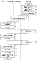
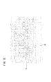
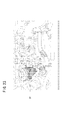
- FIG. 6 is a flow chart showing an example of work and processing on each dealer terminal side, each local corporation terminal side and management server side when a repair work commonly required depending on the model, model, year, lot number, etc. occurs.
- . 5 is a flowchart showing a part of reproduction processing of moving image data. It is a flow chart which shows the remainder of reproduction processing of animation data. It is a 1st example of the screen displayed on a monitor at the time of reproduction
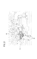
- FIG. 1 is a view showing a schematic configuration of a work procedure display system 10 (hereinafter also referred to as a “system 10”) according to an embodiment of the present invention.
- the system 10 guides a plurality of dealers (for example, dealers A1 to A4, B1, B2, C1 and C2) to repair work which is commonly required according to the type and model of the vehicle, model year, lot number, etc. It is possible.
- the system 10 includes a dealer terminal 12 (hereinafter referred to as “terminal 12”) in a plurality of dealers and a local corporation terminal 14 (hereinafter “terminal 14”) in a plurality of local corporations (for example, local corporations A, B and C).
- a management server 16 hereinafter referred to as "server 16" installed in the management center.
- the terminals 12 and 14 are a plurality of countries or regions in the world (for example, Japan, East Asia, Southeast Asia, West Asia, North Asia, South Asia, North America, Central America, South America, Northern Europe, Southern Europe, Western Europe, Eastern Europe, Oceania, etc. countries or regions).
- the server 16 is arranged in a specific country (for example, Japan).
- each of the terminals 12 and 14 and the server 16 can communicate via a communication network 18 including, for example, the Internet.
- Each terminal 12 includes a communication device 20, an input device 22 including a keyboard and a mouse, a monitor 24, an arithmetic device 26, and a storage device 28.
- Each terminal 14 also has the same configuration as that of the terminal 12.
- the server 16 includes a communication device 30, an input device 32, a monitor 34, an arithmetic device 36, a storage device 38, an update program database 50 (hereinafter also referred to as “update program DB 50”), and a moving image database 52 (hereinafter referred to Also referred to as “moving picture DB 52”.
- update program database 50 hereinafter also referred to as "update program DB 50”
- moving image database 52 hereinafter referred to Also referred to as “moving picture DB 52”.
- the update program DB 50 stores update programs that are commonly required according to the vehicle type, model, year, lot number and the like.
- the moving picture DB 52 stores moving picture data of repair work which is commonly required according to the type of vehicle, model, year, lot number and the like.
- Figure 2 shows the respective terminals 12 side, each terminal 14 side, and the server 16 side when a repair work that is commonly required according to the vehicle type, model, year, lot number, etc. occurs. It is a flow chart which shows an example of work and processing in.
- ECU electronice control unit
- EGR exhaust gas recirculation device
- the manager of the server 16 or a person similar thereto arranges the update program P1 of the ECU and the moving image data D1 for removing the EGR valve 72.
- the moving image data D1 is data of an electronic manual that describes the work procedure for removing the EGR valve 72, but basically does not include audio and text data. However, voice and / or text data may be additionally included.
- step S1 the administrator of the server 16 stores the update program P1 of the ECU in the update program DB 50 of the server 16 via the input device 32, and uploads the update program P1.
- step S2 the administrator of the server 16 stores the moving image data D1 in the moving image data DB 52 via the input device 32, and uploads the moving image data D1.
- the contents of the video data D1 will be described later.
- step S3 the manager of the server 16 specifies the local corporation in the country or region where the vehicle requiring the repair work is sold, and the terminal 14 of these local corporations is given 2) A message indicating that it is necessary to update the program of the ECU and replace the EGR valve 72, (3) a method for obtaining the update program P1 (including a password for downloading) and a message regarding the method for updating the program, (4) the EGR valve An electronic mail including a message or the like regarding an outline (including a password for download) of the method for acquiring the replacement electronic manual (moving image data D1) 72 is transmitted through the communication device 30.
- the electronic mail is created in the language (for example, Japanese) of the country for the terminal 14 existing in the country in which the server 16 is located. Also, for other countries, it is created in a language used worldwide (eg, English).
- the administrator of the server 16 can create or arrange each email in a relatively short time. If the administrator of the server 16 can create or arrange e-mails of other languages in a relatively short time and at low cost, the e-mails of the languages can be sent to the terminals 14 of the countries using the languages. It can also be sent.
- step S4 the terminal 14 receives an electronic mail from the server 16 via the communication network 18 and a communication device (not shown).
- the person in charge of each local corporation confirms the contents of the electronic mail and transfers the electronic mail from the terminal 14 to the terminal 12 of each dealer in the country.
- part or all of the e-mail may be translated into the language of the country.
- step S5 the terminal 12 receives an electronic mail from the terminal 14 via the communication network 18 and the communication device 20.
- the manager or user of the terminal 12 confirms the content of the received electronic mail. Thereby, the manager or user of the terminal 12 can know the acquisition method of the update program P1 and the update method of the program, as well as the acquisition method of the electronic manual (moving image data D1) for replacing the EGR valve 72 .
- step S6 the administrator or user of the terminal 12 operates the input device 22 according to the contents described in the electronic mail, and requests the server 16 for the update program P1 via the communication device 20.
- step S7 the server 16 automatically transmits the update program P1 to the communication device 20 of the terminal 12 in accordance with the request from the terminal 12.
- the server 16 requests the terminal 12 for a password for downloading the update program P1, and the server 16 confirms that the password received is correct before updating.
- the program P1 may be transmitted.
- step S8 the terminal 12 receives (downloads) the update program P1 from the server 16 via the communication device 20, and stores the update program P1 in the storage device 28 according to the input to the input device 22.
- step S9 the administrator or user of the terminal 12 operates the input device 22 according to the contents described in the electronic mail, and requests the server 16 for the moving image data D1 via the communication device 20.
- step S ⁇ b> 10 the server 16 automatically transmits the moving image data D ⁇ b> 1 to the communication device 20 of the terminal 12 in accordance with the request from the terminal 12.
- the server 16 requests the terminal 12 for a password for downloading the moving image data D1, and the moving image data D1 is confirmed after the server 16 confirms that the password received is correct.
- Data D1 may be transmitted.
- step S11 the terminal 12 receives (downloads) the moving image data D1 from the server 16 via the communication device 20, and stores the moving image data D1 in the storage device 28 according to the input to the input device 22.
- downloading of the update program P1 and the moving image data D1 may be performed collectively, and downloading of the updating program P1 and the moving image data D1 may be permitted by inputting a common password once.
- step S12 the worker (the manager of the terminal 12, the user, or the other person; the same applies hereinafter) operates the input device 22 to reproduce the moving image data D1 stored in the storage device 28, and the work content is displayed. Confirm (the contents of the moving image data D1 will be described later).
- step S13 the worker uses the update program P1 stored in the storage device 28 to update the program of the ECU of the target vehicle.
- the update program P1 is copied from the terminal 12 to a portable device (not shown) for program update, and the portable device is connected to the ECU of the target vehicle via the communication cable. Then, the operator operates the portable device to update the program of the ECU.
- step S14 the operator exchanges the EGR valve 72 in accordance with the contents of the moving image data D1.
- FIGS. 3 and 4 are flowcharts showing reproduction processing of the moving image data D1.
- part of the actual work for replacing the EGR valve 72 is omitted and described.
- 5 to 23 show examples of screens displayed on the monitor 24 at the time of reproduction of the moving image data D1.
- the arithmetic unit 26 reads the moving image data D1 from the storage device 28 and causes the monitor 24 to display the data.
- step S21 the monitor 24 displays an initial screen (FIG. 5) of the first work scene Sc1.
- the first work scene Sc1 is a scene where the engine 70 (FIG. 6) as a target part (current target part) at the present time is removed, and the front part of the vehicle 60 with the bonnet 62 closed is shown on its initial screen. It is done.
- a single color shade (gray scale) is displayed as a whole, only the headlights 64 are displayed light (gray), and the other parts are displayed in black.
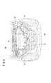
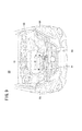
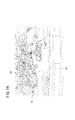
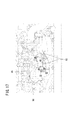
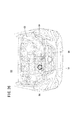
- step S22 on the monitor 24, while the bonnet 62 is opened, the density of the line indicating the bonnet 62 is gradually lowered to fade out the bonnet 62. As a result, as shown in FIG. 6, the engine room 68 is exposed. In this state, the inside of the engine room 68 is displayed by lines of a single color and the same density. However, the surface of the EGR valve 72, which is the final target part for removal (the final target part), is displayed in gray.
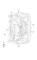
- step S23 the monitor 24 gradually reduces the concentration of the line indicating the region other than the engine 70 and the EGR valve 72 in the engine room 68 (see FIG. 7).
- the concentration of the line indicating the region other than the engine 70 and the EGR valve 72 in the engine room 68 see FIG. 7.
- the density of the line indicating the other part is set to 48. Therefore, the engine 70 and the EGR valve 72 are emphasized.
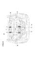
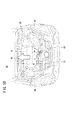
- step S24 the monitor 24 displays the removal operation associated with the engine 70 which is the current target part. Specifically, a red arrow 74 indicating the position of each of the four bolt caps 76 fixing the engine 70 is lighted and displayed for 0.5 seconds, and then a cycle of lighting off and displaying for 0.5 seconds is repeated three times. , Blink three times (see FIG. 8). The red arrow 74 is painted in red, which is not visible in FIG. 8, and indicates that the bolt cap 76 is to be removed.
- step S25 the monitor 24 displays, as an animation video, the removal of the bolt cap 76 from the engine 70 (see FIG. 9). After removal, the bolt cap 76 fades out.
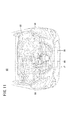
- step S26 the monitor 24 displays the removal (movement) operation of the engine 70.
- the white arrow 80 pointing to the direction of removing (moving) the engine 70 is lit and displayed for 0.5 seconds, and then it is blinked three times by repeating a cycle of displaying the light off for 0.5 seconds three times (( See Figure 10).
- the white arrow 80 for example, displays the frame in red and the inside of the frame in white, and indicates the direction in which the engine 70 is moved.
- step S27 the monitor 24 starts moving the engine 70 to the upper side of the screen 0.5 seconds after the white arrow 80 disappears, and gradually moves the density of the line indicating the engine 70 while moving it. Lower and fade the engine 70 out. As a result, in the engine room 68, only the EGR valve 72 is displayed dark.
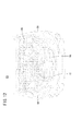
- step S28 the monitor 24 displays the removal (movement) operation of the EGR valve 72 which is the next target part (here, the final target part).
- the white arrow 80 indicating the direction in which the EGR valve 72 is removed (moved) is blinked three times in the same manner as the lighting display and the light-off display described above (see FIG. 11). Similar to the white arrow 80 in FIG. 10, the white arrow 80 represents, for example, the frame in red and the inside of the frame in white, and indicates the direction in which the EGR valve 72 is moved.
- the EGR valve 72 is not actually removed, but it is only indicated that the EGR valve 72 should be removed.
- step S29 the monitor 24 gradually reduces the density of the line over the entire screen (see FIG. 12) to fade out the entire vehicle 60 and finally completely erase the entire vehicle 60 from the screen.
- step S30 in FIG. 4 the monitor 24 starts decreasing the line density 0.5 seconds after the white arrow 80 disappears, and then fades in the initial screen of the second work scene Sc2 ( See Figure 13).
- the second work scene Sc2 is a scene where the EGR valve 72 as a target part (the final target part in the present embodiment) following the first work scene Sc1 is removed, and on the screen (FIG. 14) in which fade-in is completed, the EGR valve A state where 72 is hidden by the front grille 66 is shown.
- the entire screen is displayed in single-color shade (gray scale), and all portions are displayed in black (for example, density 256 for 256 gradations).
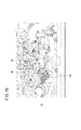
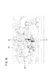
- step S31 the monitor 24 fades out the front grille 66 shielding the EGR valve 72 and exposes the EGR valve 72 in the screen (see FIG. 15).
- step S32 the monitor 24 gradually reduces the concentration of a line indicating a portion other than the EGR valve 72 in the engine room 68 (see FIG. 16).
- the density of the line indicating the EGR valve 72 is 256 (highest density) of the 256 gradations, the density of the line indicating the other portion is set to 48. Therefore, the EGR valve 72 is emphasized.
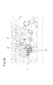
- step S33 a plurality of operations required to remove the EGR valve 72 are sequentially displayed in the second operation scene Sc2.
- components nut 82, bolt 84, etc. in FIG. 16 and FIG. 17
- an animation video shows how the parts are actually removed.
- parts tubes 86 and so on in FIG.
- the removal (movement) direction is indicated by the blinking display of the white arrow 80 as described above, and as described above
- the state of actual removal after 0.5 seconds has elapsed is displayed as an animation moving image (in this case, the density of the line indicating the relevant part is reduced after removal or removal).
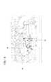
- the red arrow 74 indicating the position of the bolt 84 is blinked three times as described above (see FIG. 20).
- an animation video showing that the bolt 84 is actually removed is displayed (see FIG. 21).
- the removed bolt 84 is faded out.
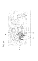
- the monitor 24 displays the removal (movement) operation of the EGR valve 72.
- the white arrow 80 indicating the direction in which the EGR valve 72 is removed (moved) is blinked three times as described above (see FIG. 22). Similar to the white arrow 80 in FIG.
- the white arrow 80 represents, for example, the frame in red and the inside of the frame in white, and indicates the direction in which the EGR valve 72 is moved. Then, after 0.5 seconds have passed since the light was turned off, the monitor 24 displays an animation moving picture showing that the EGR valve 72 is removed (see FIG. 23).
- the monitor 24 increases the density of the line in the entire screen of the second work scene (makes it the darkest state) in step S34 of FIG. Indicates that it was done.
- FIGS. 24 and 25 the display of the monitor 24 from the first work scene Sc1 to the second work scene Sc2 is shown along the time axis.
- one row is set to be an integral multiple of 0.5 seconds or 0.5 seconds. Therefore, in the present embodiment, various displays are performed along a constant rhythm.
- the target parts (the engine 70 and the EGR valve 72) and the other parts are divided and displayed in single color shades (gray scale). For this reason, since the parts (engine 70 and the EGR valve 72) which are expressed in high density appear to be emphasized, it is easy for the operator to grasp the target part even without voice or text.
- the position of the work site (bolt cap 76, nut 82, bolt 84 etc.) in the target part (engine 70 and EGR valve 72) is emphasized by the red arrow 74, and the target part (engine 70 and EGR valve 72) or
- the viewpoint of the worker is guided to the target part or the work part. For this reason, the possibility of overlooking the timing of the start of the animation moving image to be performed thereafter becomes low.
- the effect of guiding the viewpoint of the operator and the timing of movement start can be easily grasped and the oversight is suppressed. It is possible to raise
- voice or text data when voice or text data is not included in the moving image data D1, it is possible to shorten the time required to prepare the moving image data D1. In addition, since it is not necessary to use voice or text data, it is possible to reduce the data amount of the moving image data D1. Furthermore, since the data of speech and sentences become unnecessary, their translation also becomes unnecessary. Therefore, it is possible to reduce the time and cost for the translation, and to quickly notify the working procedure to repair plants, dealers and the like in different countries or regions with different languages.
- the screen of the monitor 24 is displayed in a single color, the degree of visual fatigue is reduced and it is easy to view.
- the rhythms of blinking of the red arrow 74 and the white arrow 80 and the rhythm of development of the animation moving image are set to be a base (reference) of a common rhythm (see FIGS. 24 and 25).
- the screen of the first work scene Sc1 before switching is performed based on the rhythm common to the blinking of the red arrow 74 and the white arrow 80.
- the screen of the second work scene Sc2 after switching is faded in at a timing based on the rhythm common to the blinking of the red arrow 74 and the white arrow 80.
- the nut 82 is displayed in a transparent manner by displaying only the outline 90 of the outer periphery of the shielding portion that blocks the nut 82 in front of the nut 82. This makes it possible to guide the operation on the nut 82 without changing the viewpoint even when the shielded portion is present.
- the vehicle 60 (four-wheeled vehicle) has been mentioned as the object of repair, but not limited to this, for example, mobile objects such as two-wheeled vehicles, electric bicycles, aircraft, ships, helicopters etc. can be repaired .
- mobile objects such as two-wheeled vehicles, electric bicycles, aircraft, ships, helicopters etc.
- it may be another device or apparatus.
- the operation to be displayed is not limited to that for repair, but may be for assembly, attachment, and the like.
- the moving image data D1 is the data of the electronic manual for explaining the removal of the target part (the engine 70 and the EGR valve 72), but may be the data of the electronic manual for explaining the attachment of the target part .
- the moving image data D1 basically does not include audio and text data, but may not include audio and text data at all. Alternatively, it may include audio and / or text data.
- the other parts may be replaced, attached or removed. At this time, if it is necessary to replace the defective part with a new part that has been corrected, it is necessary to send the new part to dealers in each country in advance.
- the screens in each of the first work scene Sc1 and the second work scene Sc2 are shown in grayscale, but may be shown in shades of other single colors (eg, amber, blue, green). At that time, it is also possible to adjust the color of the background of the screen. For example, the background may be black and the line may be yellow.
- the red arrow 74 and the white arrow 80 are used as markings for emphasizing the position of the work site in the target part and the moving direction of the target part or the work site in the screen.
- the target part may be displayed blinking with a thick red line (see FIG. 26).
- the terminal 12 side accesses the server 16 again to download the moving image data D1.
- moving image data D1 may be attached to an e-mail.
- the present invention is not limited thereto.
- the server 12 is accessed from the terminal 12 different from the terminal 12 which received the e-mail Data D1 may be downloaded.
- the moving image data D1 is temporarily stored in the storage device 28 and the stored moving image data D1 is reproduced in the terminal 12 has been described, but the present invention is not limited thereto.
- the moving image data D1 may not be stored in the storage device 28, and at the time of replacement of the EGR valve 72, the terminal 12 may be placed near the vehicle 60 to perform replacement work while downloading the moving image data D1.
Landscapes
- Engineering & Computer Science (AREA)
- General Physics & Mathematics (AREA)
- Physics & Mathematics (AREA)
- Theoretical Computer Science (AREA)
- General Engineering & Computer Science (AREA)
- Software Systems (AREA)
- Computer Hardware Design (AREA)
- Computer Graphics (AREA)
- Architecture (AREA)
- Automation & Control Theory (AREA)
- User Interface Of Digital Computer (AREA)
- Processing Or Creating Images (AREA)
- Management, Administration, Business Operations System, And Electronic Commerce (AREA)
- General Factory Administration (AREA)
- Controls And Circuits For Display Device (AREA)
- Digital Computer Display Output (AREA)
Priority Applications (3)
| Application Number | Priority Date | Filing Date | Title |
|---|---|---|---|
| BR112012030677A BR112012030677A2 (pt) | 2010-06-03 | 2011-01-25 | método de exibição de sequência de operação e sistema de exibição de sequência de operação |
| US13/701,084 US9349203B2 (en) | 2010-06-03 | 2011-01-25 | Operation sequence display method and operation sequence display system |
| CN201180027278.2A CN102985953B (zh) | 2010-06-03 | 2011-01-25 | 操作顺序显示方法和操作顺序显示系统 |
Applications Claiming Priority (2)
| Application Number | Priority Date | Filing Date | Title |
|---|---|---|---|
| JP2010127715A JP5261438B2 (ja) | 2010-06-03 | 2010-06-03 | 作業手順表示方法及び作業手順表示システム |
| JP2010-127715 | 2010-06-03 |
Publications (1)
| Publication Number | Publication Date |
|---|---|
| WO2011152078A1 true WO2011152078A1 (ja) | 2011-12-08 |
Family
ID=45066467
Family Applications (1)
| Application Number | Title | Priority Date | Filing Date |
|---|---|---|---|
| PCT/JP2011/051259 Ceased WO2011152078A1 (ja) | 2010-06-03 | 2011-01-25 | 作業手順表示方法及び作業手順表示システム |
Country Status (5)
| Country | Link |
|---|---|
| US (1) | US9349203B2 (enExample) |
| JP (1) | JP5261438B2 (enExample) |
| CN (1) | CN102985953B (enExample) |
| BR (1) | BR112012030677A2 (enExample) |
| WO (1) | WO2011152078A1 (enExample) |
Cited By (1)
| Publication number | Priority date | Publication date | Assignee | Title |
|---|---|---|---|---|
| CN119937333A (zh) * | 2023-11-03 | 2025-05-06 | 华为技术有限公司 | 场景设置方法及电子设备 |
Families Citing this family (10)
| Publication number | Priority date | Publication date | Assignee | Title |
|---|---|---|---|---|
| DE102011017305A1 (de) * | 2011-04-15 | 2012-10-18 | Abb Technology Ag | Bedien- und Beobachtungssystem für technische Anlagen |
| EP2975543A1 (en) | 2014-07-15 | 2016-01-20 | Kabushiki Kaisha Toshiba | Working process processing system and working process processing method |
| JP6253867B2 (ja) * | 2015-10-29 | 2017-12-27 | 三菱電機株式会社 | 運転支援装置 |
| CN107729023A (zh) * | 2016-12-19 | 2018-02-23 | 西安艾润物联网技术服务有限责任公司 | 引导操作应用程序的方法及装置 |
| JP6557274B2 (ja) * | 2017-03-31 | 2019-08-07 | ファナック株式会社 | 部品実装位置ガイダンス装置、部品実装位置ガイダンスシステム、及び部品実装位置ガイダンス方法 |
| JPWO2019082429A1 (ja) * | 2017-10-24 | 2020-04-02 | 三菱電機株式会社 | 製造作業支援システム、製造作業支援方法およびプログラム |
| JP7296220B2 (ja) * | 2019-03-08 | 2023-06-22 | 株式会社竹中工務店 | 支援システム、及び支援プログラム |
| CN114185297B (zh) * | 2022-02-14 | 2022-05-03 | 蔚来汽车科技(安徽)有限公司 | 车载软件升级的控制方法及设备 |
| EP4645240A1 (en) * | 2022-12-27 | 2025-11-05 | Nissan Motor Co., Ltd. | Information processing device, terminal, and information processing method |
| JP7406038B1 (ja) * | 2023-09-19 | 2023-12-26 | 株式会社日立パワーソリューションズ | 作業支援システム及び作業支援方法 |
Citations (5)
| Publication number | Priority date | Publication date | Assignee | Title |
|---|---|---|---|---|
| JPH0856393A (ja) * | 1995-07-24 | 1996-02-27 | Hitachi Ltd | プラント制御方法及び装置 |
| JP2003085579A (ja) * | 2001-09-10 | 2003-03-20 | Hitachi Constr Mach Co Ltd | 電子マニュアルのデータ作成方法、マニュアル印刷物の作成方法、電子マニュアル表示装置、電子マニュアルデータ構造を記録する記録媒体 |
| JP2004334510A (ja) * | 2003-05-07 | 2004-11-25 | Mitsubishi Electric Corp | 組立作業支援システムおよび方法 |
| JP2007323353A (ja) * | 2006-05-31 | 2007-12-13 | Toshiba It Service Kk | 3次元マニュアル及びその作成方法 |
| JP2008250813A (ja) * | 2007-03-30 | 2008-10-16 | Konami Digital Entertainment:Kk | 画像生成装置、画像処理方法、および、プログラム |
Family Cites Families (9)
| Publication number | Priority date | Publication date | Assignee | Title |
|---|---|---|---|---|
| JPH05250119A (ja) | 1992-03-10 | 1993-09-28 | Hitachi Ltd | 動画ヘルプガイダンス方法 |
| JP2002006727A (ja) * | 2000-06-27 | 2002-01-11 | Soatec Inc | マニュアル |
| JP2002140142A (ja) | 2000-11-02 | 2002-05-17 | Fujie:Kk | 電子マニュアル |
| US7546602B2 (en) * | 2001-07-10 | 2009-06-09 | Microsoft Corporation | Application program interface for network software platform |
| JP2005070247A (ja) * | 2003-08-22 | 2005-03-17 | Hitachi Electronics Service Co Ltd | 機器の動作の学習システム |
| US7903115B2 (en) * | 2007-01-07 | 2011-03-08 | Apple Inc. | Animations |
| US8717412B2 (en) * | 2007-07-18 | 2014-05-06 | Samsung Electronics Co., Ltd. | Panoramic image production |
| US8115784B2 (en) * | 2008-11-26 | 2012-02-14 | General Electric Company | Systems and methods for displaying multi-energy data |
| US20110179624A1 (en) * | 2010-01-26 | 2011-07-28 | Z-Line Designs, Inc. | Animated assembly system |
-
2010
- 2010-06-03 JP JP2010127715A patent/JP5261438B2/ja not_active Expired - Fee Related
-
2011
- 2011-01-25 BR BR112012030677A patent/BR112012030677A2/pt not_active Application Discontinuation
- 2011-01-25 US US13/701,084 patent/US9349203B2/en not_active Expired - Fee Related
- 2011-01-25 CN CN201180027278.2A patent/CN102985953B/zh not_active Expired - Fee Related
- 2011-01-25 WO PCT/JP2011/051259 patent/WO2011152078A1/ja not_active Ceased
Patent Citations (5)
| Publication number | Priority date | Publication date | Assignee | Title |
|---|---|---|---|---|
| JPH0856393A (ja) * | 1995-07-24 | 1996-02-27 | Hitachi Ltd | プラント制御方法及び装置 |
| JP2003085579A (ja) * | 2001-09-10 | 2003-03-20 | Hitachi Constr Mach Co Ltd | 電子マニュアルのデータ作成方法、マニュアル印刷物の作成方法、電子マニュアル表示装置、電子マニュアルデータ構造を記録する記録媒体 |
| JP2004334510A (ja) * | 2003-05-07 | 2004-11-25 | Mitsubishi Electric Corp | 組立作業支援システムおよび方法 |
| JP2007323353A (ja) * | 2006-05-31 | 2007-12-13 | Toshiba It Service Kk | 3次元マニュアル及びその作成方法 |
| JP2008250813A (ja) * | 2007-03-30 | 2008-10-16 | Konami Digital Entertainment:Kk | 画像生成装置、画像処理方法、および、プログラム |
Cited By (1)
| Publication number | Priority date | Publication date | Assignee | Title |
|---|---|---|---|---|
| CN119937333A (zh) * | 2023-11-03 | 2025-05-06 | 华为技术有限公司 | 场景设置方法及电子设备 |
Also Published As
| Publication number | Publication date |
|---|---|
| JP2011253422A (ja) | 2011-12-15 |
| CN102985953B (zh) | 2016-01-27 |
| JP5261438B2 (ja) | 2013-08-14 |
| US20130141440A1 (en) | 2013-06-06 |
| BR112012030677A2 (pt) | 2016-09-13 |
| CN102985953A (zh) | 2013-03-20 |
| US9349203B2 (en) | 2016-05-24 |
Similar Documents
| Publication | Publication Date | Title |
|---|---|---|
| JP5261438B2 (ja) | 作業手順表示方法及び作業手順表示システム | |
| US20200302821A1 (en) | Welding simulator | |
| CN108122447B (zh) | 一种基于vr技术的地铁车钩故障状态模拟系统 | |
| KR102154879B1 (ko) | 가상 용접 시스템 | |
| US9836994B2 (en) | Virtual welding system | |
| US9928755B2 (en) | Virtual reality GTAW and pipe welding simulator and setup | |
| KR101980500B1 (ko) | 가상 현실 파이프 용접 시뮬레이터 및 셋업 | |
| EP3111439B1 (en) | Portable virtual welding system | |
| US8911237B2 (en) | Virtual reality pipe welding simulator and setup | |
| EP2969360B1 (en) | Simulator for facilitating virtual orbital welding activity | |
| CN108766081A (zh) | 一种基于vr的汽车拆装培训系统 | |
| US20170323584A1 (en) | Systems and methods providing a computerized eyewear device to aid in welding | |
| CN102165505A (zh) | 使用实时熔池反馈在实时仿真的虚拟现实环境下提供弧焊训练的系统和方法 | |
| TW201346781A (zh) | 根據圖示實際物體的影像來定位電子顯示裝置中的圖案 | |
| CN109360453A (zh) | 基于vr的特种设备检测培训系统及方法 | |
| CN113205608A (zh) | 一种基于ar技术的磨床产品远程交互与运维系统 | |
| CA2226336A1 (en) | Method of animating an image by squiggling the edges of image features | |
| CN101351749A (zh) | 用于显示车辆维修过程的方法和设备 | |
| Ginters et al. | Virtual environment use in e-learning | |
| CN111984208B (zh) | 一种光学扩散膜片led灯条侧消光处理方法 | |
| CN118032377B (zh) | 一种adas功能测试台架及测试方法 | |
| JP2006287676A5 (enExample) | ||
| CN205508193U (zh) | 飞行模拟器可调节显示装置 | |
| CN211956778U (zh) | 一种模拟变电站设备增强现实技术培训装置 | |
| CN116206503A (zh) | 一种基于vr技术的变电站仿真系统 |
Legal Events
| Date | Code | Title | Description |
|---|---|---|---|
| WWE | Wipo information: entry into national phase |
Ref document number: 201180027278.2 Country of ref document: CN |
|
| 121 | Ep: the epo has been informed by wipo that ep was designated in this application |
Ref document number: 11789490 Country of ref document: EP Kind code of ref document: A1 |
|
| WWE | Wipo information: entry into national phase |
Ref document number: 10082/CHENP/2012 Country of ref document: IN |
|
| NENP | Non-entry into the national phase |
Ref country code: DE |
|
| WWE | Wipo information: entry into national phase |
Ref document number: 1201006251 Country of ref document: TH |
|
| WWE | Wipo information: entry into national phase |
Ref document number: 13701084 Country of ref document: US |
|
| 122 | Ep: pct application non-entry in european phase |
Ref document number: 11789490 Country of ref document: EP Kind code of ref document: A1 |
|
| REG | Reference to national code |
Ref country code: BR Ref legal event code: B01A Ref document number: 112012030677 Country of ref document: BR |
|
| ENP | Entry into the national phase |
Ref document number: 112012030677 Country of ref document: BR Kind code of ref document: A2 Effective date: 20121130 |