WO2011151994A1 - 超音波診断装置用レンズ及び超音波診断装置用プローブ - Google Patents
超音波診断装置用レンズ及び超音波診断装置用プローブ Download PDFInfo
- Publication number
- WO2011151994A1 WO2011151994A1 PCT/JP2011/002898 JP2011002898W WO2011151994A1 WO 2011151994 A1 WO2011151994 A1 WO 2011151994A1 JP 2011002898 W JP2011002898 W JP 2011002898W WO 2011151994 A1 WO2011151994 A1 WO 2011151994A1
- Authority
- WO
- WIPO (PCT)
- Prior art keywords
- lens
- ultrasonic diagnostic
- diagnostic apparatus
- urethane resin
- mass
- Prior art date
- Legal status (The legal status is an assumption and is not a legal conclusion. Google has not performed a legal analysis and makes no representation as to the accuracy of the status listed.)
- Ceased
Links
Images



Classifications
-
- A—HUMAN NECESSITIES
- A61—MEDICAL OR VETERINARY SCIENCE; HYGIENE
- A61B—DIAGNOSIS; SURGERY; IDENTIFICATION
- A61B8/00—Diagnosis using ultrasonic, sonic or infrasonic waves
- A61B8/42—Details of probe positioning or probe attachment to the patient
- A61B8/4272—Details of probe positioning or probe attachment to the patient involving the acoustic interface between the transducer and the tissue
- A61B8/4281—Details of probe positioning or probe attachment to the patient involving the acoustic interface between the transducer and the tissue characterised by sound-transmitting media or devices for coupling the transducer to the tissue
-
- A—HUMAN NECESSITIES
- A61—MEDICAL OR VETERINARY SCIENCE; HYGIENE
- A61B—DIAGNOSIS; SURGERY; IDENTIFICATION
- A61B8/00—Diagnosis using ultrasonic, sonic or infrasonic waves
- A61B8/44—Constructional features of the ultrasonic, sonic or infrasonic diagnostic device
- A61B8/4444—Constructional features of the ultrasonic, sonic or infrasonic diagnostic device related to the probe
-
- G—PHYSICS
- G01—MEASURING; TESTING
- G01S—RADIO DIRECTION-FINDING; RADIO NAVIGATION; DETERMINING DISTANCE OR VELOCITY BY USE OF RADIO WAVES; LOCATING OR PRESENCE-DETECTING BY USE OF THE REFLECTION OR RERADIATION OF RADIO WAVES; ANALOGOUS ARRANGEMENTS USING OTHER WAVES
- G01S7/00—Details of systems according to groups G01S13/00, G01S15/00, G01S17/00
- G01S7/52—Details of systems according to groups G01S13/00, G01S15/00, G01S17/00 of systems according to group G01S15/00
- G01S7/52017—Details of systems according to groups G01S13/00, G01S15/00, G01S17/00 of systems according to group G01S15/00 particularly adapted to short-range imaging
- G01S7/52079—Constructional features
Definitions
- the present invention relates to a lens for an ultrasonic diagnostic apparatus and a probe for an ultrasonic diagnostic apparatus, and more specifically, for an ultrasonic diagnostic apparatus that satisfies the acoustic characteristics of sound velocity, acoustic impedance, and acoustic attenuation rate and exhibits high wear resistance.
- the present invention relates to a lens and a probe for an ultrasonic diagnostic apparatus.
- An ultrasonic diagnostic apparatus for example, an electronic scanning ultrasonic diagnostic apparatus, includes a probe in which piezoelectric elements (also referred to as piezoelectric vibrators) are arranged to obtain an image of a subject.
- a probe is provided with a so-called “lens for an ultrasonic diagnostic apparatus” that allows ultrasonic waves to be transmitted and received through a subject in contact with the subject. Since this ultrasonic diagnostic device lens is required to have acoustic characteristics such as sound velocity, acoustic impedance, and acoustic attenuation rate, the acoustic impedance is usually close to the subject, the ultrasonic attenuation is small, and the acoustic velocity is 1500 m / second or less.
- silicone rubber It is made of some silicone rubber. Although the silicone rubber has excellent acoustic properties, it is inferior in chemical resistance, gas permeability, etc., and therefore, a lens for an ultrasonic diagnostic apparatus provided with a coating on the surface of the silicone rubber for the purpose of improving chemical resistance, gas permeability, etc. Has been proposed.
- Examples of the lens for an ultrasonic diagnostic apparatus provided with a coating include the lenses for an ultrasonic diagnostic apparatus disclosed in Patent Documents 1 to 4.
- a coating made of polyimide resin or polyester resin Patent Document 1
- a protective film containing a fluororesin Patent Document 2
- fluorine rubber layer Patent Document 3
- Resin films of polyimide resin, fluororesin, polyester resin, etc.” Patent Document 4
- the present inventors have found that the lens for an ultrasonic diagnostic apparatus provided with the coating as described above cannot sufficiently exhibit the function as a lens for an ultrasonic diagnostic apparatus because the acoustic characteristics and the like are deteriorated by the coating. Discovered.
- the lens for an ultrasonic diagnostic apparatus is slid in contact with the surface of the subject in order to obtain an image of the subject, high wear resistance is required in addition to the acoustic characteristics.
- An object of the present invention is to provide a lens for an ultrasonic diagnostic apparatus and a probe for an ultrasonic diagnostic apparatus that satisfy the acoustic characteristics of sound velocity, acoustic impedance, and acoustic attenuation rate and exhibit high wear resistance.
- a lens for an ultrasonic diagnostic apparatus as a means for solving the above problems includes a base formed of a silicone rubber composition, 100 parts by weight of a urethane resin and 3 to 7 parts by weight disposed on the outer surface of the base. And a urethane resin coat layer containing a portion of silica.
- the mass change rate by the following measurement method is preferably 0.01 to 0.2%
- the urethane resin coating layer is formed by applying a urethane resin composition containing 100 parts by mass of urethane resin and 3 to 7 parts by mass of silica to the outer surface of the substrate, and curing the applied urethane resin composition. It is preferable that (3) The urethane resin coat layer is preferably formed to a thickness of 10 to 50 ⁇ m.
- a disk-shaped test piece is prepared and mounted and fixed on a fixed table of a “wear tester” defined in Japanese Industrial Standard (JIS K6264-2).
- JIS K6264-2 Japanese Industrial Standard
- Abrasion tester is pivotally supported so that the distance between the opposing surfaces of the disc-shaped grindstone is 52 mm with the plane being the center plane.
- (3) Each of the disc-shaped grindstones is pressed against the surface of the disc-shaped test piece so that the contact surface between each of the disc-shaped grindstone polishing surfaces and the disc-shaped test piece is 1 mm ⁇ 13 mm, and the fixed base is It is made 3000 times at a rotation speed of 60 rpm. At this time, each of the disk-shaped grindstones is driven to rotate as the disk-shaped test piece rotates.
- the ultrasonic diagnostic apparatus probe as means for solving the problems is provided with a case having at least one end opened, and an end of the end exposed at the end.
- the lens for an ultrasonic diagnostic apparatus according to any one of 4; a piezoelectric element housed in the case; a matching layer disposed between the lens for an ultrasonic diagnostic apparatus and the piezoelectric element; And a backing layer disposed on the opposite side of the piezoelectric element with respect to the matching layer.
- the lens for an ultrasonic diagnostic apparatus comprises a urethane resin coating layer containing 100 parts by mass of urethane resin and 3 to 7 parts by mass of silica on the outer surface of a substrate formed of a silicone rubber composition. Therefore, high wear resistance is exhibited without greatly deteriorating the acoustic characteristics. Therefore, according to the present invention, it is possible to provide a lens for an ultrasonic diagnostic apparatus and a probe for an ultrasonic diagnostic apparatus that satisfy the acoustic characteristics of sound velocity, acoustic impedance, and acoustic attenuation rate and exhibit high wear resistance.
- FIG. 1 is a schematic view showing a lens for an ultrasonic diagnostic apparatus as an embodiment of the lens for an ultrasonic diagnostic apparatus according to the present invention
- FIG. 1 (a) is a diagram of the lens for an ultrasonic diagnostic apparatus according to the present invention
- FIG. 1 is a schematic front view showing a lens for an ultrasonic diagnostic apparatus as an embodiment
- FIG. 1B is a schematic view showing a lens for an ultrasonic diagnostic apparatus as an embodiment of the lens for an ultrasonic diagnostic apparatus according to the present invention. It is a side view.
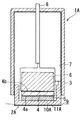
- FIG. 2 is a schematic cross-sectional view showing an example of a probe for an ultrasonic diagnostic apparatus to which a lens for an ultrasonic diagnostic apparatus according to the present invention is attached.
- FIG. 1 is a schematic view showing a lens for an ultrasonic diagnostic apparatus as an embodiment of the lens for an ultrasonic diagnostic apparatus according to the present invention
- FIG. 1 (a) is a diagram of the lens for an ultrasonic diagnostic apparatus according to the present invention.
- FIG. 3 is a schematic view showing a lens for an ultrasonic diagnostic apparatus which is another embodiment of the lens for an ultrasonic diagnostic apparatus according to the present invention
- FIG. 3 (a) is for the ultrasonic diagnostic apparatus according to the present invention
- FIG. 3 is a schematic front view showing a lens for an ultrasonic diagnostic apparatus which is another embodiment of the lens
- FIG. 3B is an ultrasonic diagnosis which is another embodiment of the lens for an ultrasonic diagnostic apparatus according to the present invention.
- It is a schematic side view which shows the lens for apparatuses.
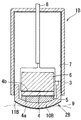
- FIG. 4 is a schematic sectional view showing another example of a probe for an ultrasonic diagnostic apparatus to which a lens for an ultrasonic diagnostic apparatus according to the present invention is attached.
- FIG. 5 is a schematic explanatory diagram for explaining a method of measuring a mass change rate in the lens for an ultrasonic diagnostic apparatus.
- the lens for an ultrasonic diagnostic apparatus includes a base and a urethane resin coat layer, and is in contact with a subject of a probe in the ultrasonic diagnostic apparatus, for example, a human body surface through olive oil or liquid paraffin. Is attached to the tip of the probe.
- a probe in the ultrasonic diagnostic apparatus for example, a human body surface through olive oil or liquid paraffin. Is attached to the tip of the probe.
- Examples of such an ultrasonic diagnostic apparatus include an electronic scanning ultrasonic diagnostic apparatus.
- Such a probe is not particularly limited, and as an example, for example, as shown in FIG. 2, a substantially cylindrical case 3 having at least one end opened, and the end of the case 3 itself Between the ultrasonic diagnostic device lens 2 ⁇ / b> A provided so as to expose the distal end portion thereof, the piezoelectric element 4 housed in the case 3, and the ultrasonic diagnostic device lens 2 ⁇ / b> A and the piezoelectric element 4.
- An example of the probe 1A includes a matching layer 5 disposed and a backing layer 6 disposed on the opposite side of the piezoelectric element 4 with respect to the matching layer 5.
- the probe 1 ⁇ / b> A is provided with a substantially cylindrical case 3 having at least one end opened, and the tip of the case 3 being exposed from the case 3 at the one end.
- a substantially cylindrical case 3 having at least one end opened, and the tip of the case 3 is exposed at the end of the case 3.
- the ultrasonic diagnostic apparatus lens 2B provided as described above, the piezoelectric element 4 housed in the case 3, and the matching layer 5 disposed between the ultrasonic diagnostic apparatus lens 2B and the piezoelectric element 4
- a probe 1B comprising a backing layer 6 disposed on the opposite side of the piezoelectric element 4 with respect to the matching layer 5. That is, the probe 1B is basically the same as the probe 1A except that the shape of the lens for an ultrasonic diagnostic apparatus is different. Therefore, although a more specific description of the probe 1B is omitted, it means that components having the same reference numerals as the components of the probe 1A are the same as the components of the probe 1A.
- ultrasonic diagnostic apparatus lenses 2A and 2B can be used without particular limitation.
- probes include various probes for ultrasonic diagnostic equipment manufactured by GE Healthcare.
- the ultrasonic diagnostic apparatus lens 2A which is an embodiment of the ultrasonic diagnostic apparatus lens according to the present invention, will be described with reference to the drawings. As shown in FIGS. 1 and 2, the ultrasonic diagnostic apparatus lens 2A includes a base body 10A and a urethane resin coat layer 11A disposed on the outer surface of the base body 10A.
- the ultrasonic diagnostic apparatus lens 2 ⁇ / b> A has a bottomed rectangular parallelepiped cylindrical body with one end opened, and the opening side is at the one end of the case 3. It is installed.
- the lens 2A for an ultrasonic diagnostic apparatus is adjusted to an appropriate shape and size according to the shape and size of the case 3 to be mounted, and the shape and size are not particularly limited.
- the ultrasonic diagnostic apparatus lens 2A has a rectangular bottom portion having a flat surface and the same thickness as the bottom portion, and is perpendicular to each edge of the bottom portion. And four side walls standing up.
- This bottom portion is formed with a plane whose outer surface is substantially perpendicular to its own axis, and this plane is the outer surface of the lens 2A for an ultrasonic diagnostic apparatus on which a urethane resin coat layer 11A described later is disposed.
- the urethane resin coat layer 11 ⁇ / b> A formed on this plane comes into contact with the subject surface 9.
- the base 10A constituting the ultrasonic diagnostic apparatus lens 2A is basically the same as the ultrasonic diagnostic apparatus lens 2A except that the urethane resin coat layer 11A is not disposed. It is the same. That is, the base 2 is a lens base that forms a lens for an ultrasonic diagnostic apparatus, and is a rectangular parallelepiped cylinder having one end opened. Specifically, as shown in FIGS. 1 and 2, the base body 2 has a rectangular bottom portion having a flat surface and the same thickness as the bottom portion, and rises vertically from each edge of the bottom portion. It has four side walls. The base 2 is also called a cap because it is attached to the opening of the case 4.
- the size of the base 10A is adjusted to an appropriate size according to the size of the case 3 to be mounted, and is not particularly limited. However, since it affects transmission / reception of ultrasonic waves, the bottom of the base 10A is not excessively thick. Is good. For example, the bottom thickness is preferably adjusted to 0.1 to 2.5 mm.
- This base 10A is formed of a silicone rubber composition to be described later.
- the urethane resin coat layer 11A is a thin film containing 100 parts by mass of urethane resin and 3 to 7 parts by mass of silica, and is disposed on the outer surface of the bottom of the substrate 10A. As shown in FIGS. 1 and 2, the urethane resin coat layer 11A only needs to be formed on the outer surface of the base 10A that contacts at least the subject surface 9, and in addition to the outer surface of the bottom, the case 3 may be formed on the outer surface of the side wall exposed from 3, or may be formed on the entire outer surface of the base body 10A.
- the base 10A has a urethane resin coat layer 11A disposed on the entire outer surface of the bottom, and the entire outer surface is covered with the urethane resin coat layer 11A.
- the urethane resin coat layer 11A is formed by curing a urethane resin composition described later.
- the urethane resin coat layer 11A is formed by applying a urethane resin composition to be described later to the outer surface of the base 10A and curing the applied urethane resin composition. Therefore, this urethane resin coat layer 11A contains a urethane resin formed of the urethane resin composition, and this urethane resin is formed of a polyol capable of forming a urethane resin and a polyisocyanate capable of forming a urethane resin. A kind etc. are not specifically limited.
- the urethane resin coat layer 11 ⁇ / b> A may contain various additives ordinarily used in various urethane resin compositions, if desired, in addition to the urethane resin.
- silica for example, fumed silica, precipitated silica or the like can be used, and surface-treated silica can also be used.
- silica is contained in the urethane resin coating layer 11A, the wear resistance of the ultrasonic diagnostic apparatus lens 2A is improved, and in some cases, a urethane resin having low adhesion to the substrate 10A is highly adhered to the substrate 10A.
- Silica can be used in the form of particles, granules, powders, etc., and the average particle diameter is preferably equal to or less than the thickness of the urethane resin coat layer 11A, for example, preferably 5 to 10 ⁇ m.
- the average particle diameter of silica is a value measured by a sieving method.
- the content of silica in the urethane resin coat layer 11A is 3 to 7 parts by mass with respect to 100 parts by mass of the urethane resin. If the content is less than 3 parts by mass, the effect of containing silica may not be sufficiently exhibited and the wear resistance may be inferior. In some cases, the adhesion between the base 10A and the urethane resin coat layer 11A may be poor. May be inferior. On the other hand, if the content exceeds 7 parts by mass, the acoustic characteristics may deteriorate. In view of well attaining the object of the present invention, the content of silica is preferably 4 to 6 parts by mass.
- the silica content in the urethane resin coat layer 11A can be measured by a thermogravimetric analysis method (JIS K7120). Specifically, after the urethane resin coat layer 11A is heated to 900 ° C., the mass of the residue is measured, and the mass that is burned down by heating as the mass of the urethane resin in the urethane resin coat layer 11A is 100 parts by mass. The ratio of the mass of the residue when it is made is the silica content.
- JIS K7120 thermogravimetric analysis method
- the urethane resin coat layer 11A preferably has a thickness of 10 to 50 ⁇ m in that it can substantially maintain the excellent acoustic characteristics of the base 10A formed of the silicone rubber composition. It is particularly preferred to have a thickness.
- the ultrasonic diagnostic apparatus lens 2B which is another embodiment of the ultrasonic diagnostic apparatus lens according to the present invention, will be described with reference to the drawings.
- the ultrasonic diagnostic apparatus lens 2B includes a base body 10B and a urethane resin coat layer 11B disposed on the outer surface of the base body 10B.
- This ultrasonic diagnostic apparatus lens 2B is basically the same as the ultrasonic diagnostic apparatus lens 2A except that its shape and dimensions differ depending on the case. That is, as shown in FIGS. 3 and 4, the ultrasonic diagnostic apparatus lens 2 ⁇ / b> B includes a rectangular cylinder having a substantially rectangular cross-sectional outline perpendicular to the axis and open at both ends, and one end edge of the cylinder. And a tip portion protruding in the axial direction toward the opposite side with respect to the end edge. For example, as shown in FIG. 4, the tip portion has the same thickness as the side wall constituting the cylinder, and the outer surface is in the longitudinal direction of the cross-sectional contour of the cylinder.
- the base body 10B constituting the lens 2B for an ultrasonic diagnostic apparatus has basically the same shape as the lens 2B for an ultrasonic diagnostic apparatus, as shown in FIGS.
- the urethane resin coat layer 11B only needs to be formed on the outer surface of the base body 10B that is in contact with at least the subject surface 9.
- the urethane resin coat layer 11B may be formed on the outer surface exposed from the case 3. Alternatively, it may be formed on the entire outer surface of the base body 10B. In this example, the urethane resin coat layer 11B is formed on the entire surface of the arcuate curved surface.
- a urethane resin coat layer 11B is disposed on the entire outer surface of the arcuate curved surface, and the entire arcuate curved surface is covered with the urethane resin coat layer 11B.
- the ultrasonic diagnostic apparatus lenses 2A and 2B having the above-described configuration (hereinafter sometimes referred to as the ultrasonic diagnostic apparatus lens 2) have a sound velocity c of 900 to 1600 m / s, which is close to the sound velocity of a living tissue. It is preferable.
- the sound velocity c of the ultrasonic diagnostic apparatus lens 2A is a urethane resin coating layer 11A of a test piece cut out from the ultrasonic diagnostic apparatus lens 2 or a flat test piece produced in the same manner as the ultrasonic diagnostic apparatus lens 2.
- ultrasonic waves Longitudinal waves with a frequency of 5 MHz
- urethane resin coat layer 11 reflected on the other surface, that is, the back surface
- It is a value (m / s) obtained by measuring the time with an ultrasonic thickness meter “Echometer 1060” (manufactured by Nippon Matec Co., Ltd.) and dividing the measured time by the thickness t of the test piece.
- the ultrasonic diagnostic device lens 2 is 1.30 to 1.60 (kg / (m) close to the acoustic impedance of the living body in that the reflection of ultrasonic waves between the living body and the acoustic lens can be minimized. 2 ⁇ S ⁇ 10 6 )) is preferable.
- the acoustic impedance can be obtained from the specific gravity ⁇ (g / cm 3 ) of the lens 2 for an ultrasonic diagnostic apparatus and the sound velocity c (m / s) by the formula: ⁇ ⁇ c.
- the sound speed c can be obtained by the measurement method.
- the specific gravity ⁇ can be obtained by dividing the mass (g) of the ultrasonic diagnostic lens 2 by its volume (cm 3 ).
- the lens 2 for an ultrasonic diagnostic apparatus can transmit and receive ultrasonic waves with high sensitivity and can obtain a high-quality image, and has a small acoustic attenuation rate in a longitudinal wave with a frequency of 1 to 5 MHz, for example, with a frequency of 4.5 MHz.
- the acoustic attenuation factor (4.5 MHz) in the longitudinal wave is preferably 3.0 dB / mm or less, more preferably 2.6 dB / mm or less, and 1.1 to 1.7 dB / mm. Is particularly preferred.
- the acoustic attenuation rate can be obtained from the formula: 20 ⁇ log 10 [(strength B1 / strength B2) / (thickness ⁇ 2)].
- the intensity B1 is transmitted in the thickness direction from one surface of the lens 2 for ultrasonic diagnostic equipment to the other surface with an ultrasonic frequency of 4.5 MHz, and is reflected by the other surface and returned.
- the intensity value of the ultrasonic wave when the ultrasonic wave is received by the one surface that is, the ultrasonic wave transmitted to the ultrasonic diagnostic apparatus lens 2 makes one round trip in the thickness direction of the ultrasonic diagnostic apparatus lens 2.
- the intensity B2 is the intensity of the ultrasonic wave when it returns to the transmission position, and the intensity B2 is similarly transmitted twice to the ultrasonic diagnostic apparatus lens 2 in the thickness direction by the ultrasonic wave transmitted to the ultrasonic diagnostic apparatus lens 2. The intensity of the ultrasonic wave when returning to the transmission position.
- the thickness is the thickness of the portion of the ultrasonic diagnostic device lens 2 where the ultrasonic wave is transmitted, that is, the total thickness of the urethane resin coat portion 11 and the base 10A of this portion, and the thickness of the ultrasonic diagnostic device lens 2A. In this case, it is the thickness of the bottom, and in the case of the ultrasonic diagnostic apparatus lens 2B, it is the thickness of the tip, more specifically, the thickness at the center of the tip.
- the acoustic attenuation rate can be measured using, for example, an ultrasonic thickness meter (type “Echometer 1060”, manufactured by Nippon Matec Co., Ltd.).
- the ultrasonic diagnostic lens 2 has excellent wear resistance.
- the lens 2 for an ultrasonic diagnostic apparatus preferably has a mass change rate of 0.01 to 0.2%, particularly preferably 0.01 to 0.1%, according to the following test. If the rate of mass change of the ultrasonic diagnostic device lens 2 is within the above range, the ultrasonic diagnostic device lens 2 is in contact with the subject surface 9 even when mounted on the probe for ultrasonic diagnostic device. Even when sliding, not only the substrates 10A and 10B (hereinafter also referred to as the substrate 10), but also the urethane resin coat layer 11 can maintain the initial state over a long period of time.
- the mass change rate is determined as follows using a “wear tester” (for example, the trade name “Taber Ablation Tester”, manufactured by Yasuda Seiki Seisakusyo Co., Ltd.) defined in the Japanese Industrial Standard (JIS K6264-2). Can be requested.
- FIG. 5 is a schematic explanatory diagram for explaining a method of measuring a mass change rate.
- the same material as that for forming the lens 2 for an ultrasonic diagnostic apparatus whose mass change rate is to be measured is prepared.
- the component 10 and the content of the base 10 and the urethane resin coat layer 11 of the ultrasonic diagnostic apparatus lens 2 for which the mass change rate is to be measured are specified by chemical analysis, etc., and the specified component and The same components and materials as the content are prepared.
- Each of these materials is cured under appropriate conditions, and a disk-shaped test piece having a diameter of 125 mm (thickness: 2.015 mm) comprising a silicone rubber layer and a urethane resin coating layer disposed on the silicone rubber layer. 24 is produced.
- each of the silicone rubber layer and the urethane resin coat layer is determined so long as the mass change rate can be measured.
- the thickness of each urethane resin coat layer may be the same or different.
- the thickness of the silicone rubber layer can be set to 2.000 mm, and the thickness of the urethane resin coat layer 11 can be set to 0.015 mm.
- the mass (referred to as initial mass) of the disc-shaped test piece 24 thus produced is measured in advance.
- This disk-shaped test piece 24 is placed on and fixed to the fixed base 22 of the wear tester 21.
- the surface 25 of the disk-shaped test piece 24 is adjusted to the same surface roughness Rz as the surface roughness Rz of the lens 2 for an ultrasonic diagnostic apparatus.
- each of the disk-shaped grindstones 27A and 27B has a disk shape having a circumferential side surface of 160 mm in circumference and a thickness of 13 mm, and the circumferential side surfaces are polished surfaces 28A and 28B.
- a grindstone of a model number “CS-17” manufactured by TABER INDUSTRIES
- these two disc-shaped grindstones 27 ⁇ / b> A and 27 ⁇ / b> B are perpendicular to the plane L including the axis C t of the disc-shaped test piece 24 whose axis C gs is fixed to the fixing base 22.
- the axis C gs is pivotally supported by the wear tester 21 so as to be parallel to the surface 25 of the disk-shaped test piece 24 fixed to the fixed base 22.
- the wear test is performed on the two disc-shaped grindstones 27A and 27B so that the distance d between the opposed surfaces 29A and 29B is 52 mm with the plane L being the center plane. It is pivotally supported on the machine 21.
- the contact surfaces of the polishing surfaces 28A and 28B of the disc-shaped grindstones 27A and 27B and the surface 25 of the disc-shaped test piece 24 are 1 mm in the circumferential length of the disc-shaped grindstones 27A and 27B, and the thickness of the disc-shaped grindstones 27A and 27B.
- the disc-shaped grindstones 27A and 27B are pressed against the surface 25 of the disc-shaped test piece 24 so that the length in the length direction is 13 mm.
- the fixed base 22 is rotated 3000 in one direction at a rotational speed of 60 rpm together with the disk-shaped test piece 24 while maintaining this pressure contact state.
- each of the disc-shaped grindstones 27 ⁇ / b> A and 27 ⁇ / b> B is driven to rotate on the surface 25 of the disc-shaped test piece 24 around the axis C gs as the disc-shaped test piece 24 rotates.
- the disk-shaped test piece 24 is removed from the fixed base 22 and its mass (sometimes referred to as a mass after 3000 rotations) is measured.
- the difference between the initial mass and the mass after 3000 rotations in the disc-shaped test piece 24 is obtained, and the percentage of the difference with respect to the initial mass is defined as the mass change rate (%) of the lens 2 for an ultrasonic diagnostic apparatus.
- the lens 2 for an ultrasonic diagnostic apparatus has a thickness change rate according to the following test of 0.1 to 13% in place of the mass change rate or together with the mass change rate. It is preferable that the content is 0.1 to 11%.
- the thickness change rate of the ultrasound diagnostic device lens 2 is within the above range, the ultrasound diagnostic device lens 2 is in contact with the subject surface 9 even if the ultrasound diagnostic device lens 2 is mounted on the probe. Even if it is slid, the base 10 and the urethane resin coat layer 11 can maintain the initial state for a long period of time.
- the thickness change rate can be obtained by measuring the initial thickness of the urethane resin coat layer and the thickness after 3000 rotations before and after the measurement method basically performed in the same manner as the measurement of the mass change rate.
- the thickness after 3000 rotations is the thickness of the portion where the disc-shaped grindstones 27A and 27B are in pressure contact with each other in the urethane resin coat layer.
- the thickness of the urethane resin coating layer can be measured using a non-contact film thickness meter, for example, a trade name “Shape Measurement Microscope VK-8700 Generation II” (manufactured by Keyence Corporation).
- the lens 2 for an ultrasonic diagnostic apparatus preferably has a thickness of a portion in contact with the subject surface 9 of 0.1 to 2.5 mm in order to suppress the attenuation of ultrasonic energy transmitted from the vibrator as much as possible. .
- the lens 2 for an ultrasonic diagnostic apparatus preferably has a surface roughness Rz of 6 to 15 ⁇ m on the outer surface thereof, that is, the outer surface of the urethane resin coat layer 11, particularly the outer surface in contact with the subject surface 9.
- a thickness of 12 ⁇ m is particularly preferable.
- This surface roughness Rz is the “ten point average roughness” defined in JIS B0601-1994. According to the method of JIS B0601-1994, the tip diameter of the stylus for rubber is 5 ⁇ m, the load is 0.07 g, and the speed is 0.12 mm. / sec, measurement length of 0.4 mm, test piece thickness of 2.015 mm, and cutoff wavelength of 0.8 mm can be measured with a cutoff type Gaussian.
- the lens 2 for an ultrasonic diagnostic apparatus is a method in which a base 10 is made with a silicone rubber composition and then a urethane resin composition is applied and cured on the outer surface of the base 10.
- a thin film is made with the urethane resin composition.
- a primer may be applied to the outer surface of the substrate 10.
- the silicone rubber composition only needs to contain a silicone rubber, and examples thereof include a silicone rubber composition containing a silicone rubber having a dimethylpolysiloxane structure containing a vinyl group, silica, and a vulcanizing agent.
- the silicone rubber composition is preferably a so-called “millable type” when used in a method for producing a lens for an ultrasonic diagnostic apparatus according to the present invention described later.
- the vulcanizing agent those generally used as a vulcanizing agent for silicone rubber can be used without any particular limitation.
- Specific examples of the silicone rubber composition forming the substrate 10 include, for example, “a silicone rubber having a dimethylpolysiloxane structure containing a vinyl group and a mass ratio with respect to the silicone rubber” described in Japanese Patent No.
- the silicone rubber composition containing the silicone rubber and silica includes, for example, a trade name “KE-981U” (manufactured by Shin-Etsu Chemical Co., Ltd.), a trade name “KE-971U”, Examples include trade names “KE-752U” and “KE-772” (both manufactured by Shin-Etsu Chemical Co., Ltd.).
- the urethane resin composition is a composition containing 100 parts by mass of a component that forms a urethane resin and / or urethane resin, and 3 to 7 parts by mass of silica with respect to the urethane resin and / or 100 parts by mass of the component. is there.
- a component which forms the said urethane resin a polyol and polyisocyanate, or the urethane prepolymer formed by reacting these, etc. are mentioned, for example,
- the silica which a urethane resin composition contains is as above-mentioned.
- the polyol may be any of various polyols usually used for preparing polyurethanes, preferably having at least two hydroxyl groups in the molecule.
- the polyol is preferably at least one polyol selected from polyether polyols and polyester polyols, and polyester polyols are more preferable in terms of excellent thermal stability.
- the polyether polyol include polyalkylene glycols such as polyethylene glycol, polypropylene glycol, and polypropylene glycol-ethylene glycol, polytetramethylene ether glycol, copolymer polyols of tetrahydrofuran and alkylene oxide, and various modified products thereof. These mixtures etc. are mentioned.
- polyester polyol examples include a polyester polyol, a lactone polyester polyol, a polycarbonate polyol, and a mixture thereof obtained by condensation of a dicarboxylic acid such as adipic acid and a polyol such as ethylene glycol and hexanediol. .
- the polyol is preferably a diol, and therefore more preferably a polyester diol or a polyether diol, and particularly preferably a polyester diol.
- the polyol preferably has a number average molecular weight of 800 to 15000, more preferably 1000 to 5000, from the viewpoint of excellent compatibility with polyisocyanate and the like described later.
- the number average molecular weight is a molecular weight when converted to standard polystyrene by gel permeation chromatography (GPC).
- GPC gel permeation chromatography
- the said polyol may be used individually by 1 type or in combination of 2 or more types, and may be used combining polyether polyol and polyester polyol.
- the polyisocyanate may be any of various polyisocyanates usually used in the preparation of polyurethane having at least two isocyanate groups in the molecule, and examples thereof include aliphatic polyisocyanates, aromatic polyisocyanates and these polyisocyanates. Derivatives and the like.
- Aromatic polyisocyanates include, for example, xylylene diisocyanate (XDI), diphenylmethane diisocyanate (MDI), toluene diisocyanate (also referred to as tolylene diisocyanate, TDI), 3,3′-bitrylene-4,4′-diisocyanate, 3 , 3′-dimethyldiphenylmethane-4,4′-diisocyanate, 2,4-tolylene diisocyanate uretidinedione (a dimer of 2,4-TDI), xylene diisocyanate, naphthalene diisocyanate (NDI), paraphenylene diisocyanate (PDI) ), Tolidine diisocyanate (TODI), metaphenylene diisocyanate and the like.
- XDI xylylene diisocyanate
- MDI diphenylmethane diisocyanate
- TDI tolu
- aliphatic polyisocyanates examples include hexamethylene diisocyanate (HDI), 4,4′-dicyclohexylmethane diisocyanate (hydrogenated MDI), orthotoluidine diisocyanate, lysine diisocyanate methyl ester, isophorone diisocyanate (IPDI), norbornane diisocyanate methyl, trans Examples include cyclohexane-1,4-diisocyanate and triphenylmethane-4,4 ′, 4 ′′ -triisocyanate.
- HDI hexamethylene diisocyanate
- MDI 4,4′-dicyclohexylmethane diisocyanate
- IPDI isophorone diisocyanate
- trans examples include cyclohexane-1,4-diisocyanate and triphenylmethane-4,4 ′, 4 ′′ -triisocyanate.
- derivatives include polynuclear polyisocyanates, urethane-modified products modified with polyols (including urethane prepolymers), dimers formed by uretidione formation, isocyanurate-modified products, carbodiimide-modified products, uretonimine-modified products, and allophanate-modified products. Products, urea-modified products, and burette-modified products.
- the polyisocyanate is preferably a diisocyanate, and thus is particularly preferably an aliphatic diisocyanate.
- the polyisocyanate preferably has a molecular weight of 500 to 2000, more preferably 700 to 1500.
- the said polyisocyanate can be used individually by 1 type or 2 types or more.
- the urethane resin and the urethane prepolymer are obtained by reacting the polyol and the polyisocyanate in a mixing ratio described later.
- the mixing ratio of the polyol and the polyisocyanate is such that the ratio [NCO / OH] of the number of moles of hydroxyl group (OH) contained in the polyol to the number of moles of isocyanate group (NCO) contained in the polyisocyanate is 0.7. It is preferably ⁇ 1.15. This ratio [NCO / OH] is more preferably 0.85 to 1.10. From the viewpoint that hydrolysis of polyurethane can be prevented. However, in practice, an amount corresponding to 3 to 4 times the appropriate molar ratio may be blended in consideration of work environment and work errors.
- the urethane composition may optionally be a solvent, an auxiliary agent usually used in the reaction of the polyol and the polyisocyanate, for example, a chain extender, a crosslinking agent.
- a chain extender for example, a chain extender, a crosslinking agent.
- An agent or the like may be contained. Examples of chain extenders and crosslinking agents include glycols, hexanetriol, trimethylolpropane, and amines.
- the urethane resin composition is prepared by mixing 100 parts by mass of a urethane resin and / or a component that forms a urethane resin, 3 to 7 parts by mass of silica, and an appropriate amount of a solvent and an appropriate amount of an auxiliary agent, if necessary. can get.
- a preferred method for manufacturing the lens 2 for an ultrasonic diagnostic apparatus will be specifically described.
- a molding method using a mold or the like is usually selected. For example, using a molding die comprising a first mold having a convex part and a second mold having a concave part into which the convex part can enter, the mold is arranged between the convex part and the concave part.
- the silicone rubber composition is compression-molded, the substrate 10 is produced.
- the gap shape between the convex portion and the concave portion of the molding die matches the shape of the base 10.
- the silicone rubber composition is heated under the condition that the silicone rubber composition is cured simultaneously with or after the compression of the silicone rubber composition by the molding die.
- the silicone rubber composition is cured when heated at a temperature of 155 ° C. or higher for about 3 to 10 minutes. After curing the silicone rubber composition in this manner, secondary heating may be performed as desired.
- the compression molded product is taken out from the molding die, and deburring or the like is performed as desired, whereby the substrate 10 can be manufactured.
- a urethane resin composition containing 100 parts by mass of urethane resin and 3 to 7 parts by mass of silica is applied to the outer surface of the substrate 10 thus prepared.
- the urethane resin composition can be applied by a known method such as a spray method, a brush coating method, or a dip method.
- the urethane resin composition applied to the outer surface of the substrate 10 is cured.
- the urethane resin composition can be cured by heating and / or moisture.
- the lens 2 for an ultrasonic diagnostic apparatus can be manufactured.
- the lens 2 for an ultrasonic diagnostic apparatus Since the lens 2 for an ultrasonic diagnostic apparatus has the above-described configuration, it exhibits high wear resistance without greatly deteriorating acoustic characteristics. Therefore, according to the present invention, it is possible to provide a lens for an ultrasonic diagnostic apparatus and a probe for an ultrasonic diagnostic apparatus that satisfy the acoustic characteristics of sound velocity, acoustic impedance, and acoustic attenuation rate and exhibit high wear resistance.
- the base 10 is made of a silicone rubber composition, and the thin urethane resin coat layer 11 is disposed on the outer surface thereof.
- the slidability is high and the contact property to the subject surface 9 is also good.
- the lens 2 for an ultrasonic diagnostic apparatus is excellent in durability because the urethane resin coating layer 11 contains silica and has high adhesion to the base 10 and can follow the deformation of the base 10 well during use. .
- the lens for an ultrasonic diagnostic apparatus is not limited to the above-described embodiment, and various modifications can be made within a range in which the object of the present invention can be achieved.
- the lens for an ultrasonic diagnostic apparatus does not need to be formed in a quadrangular prism shape, and may be formed in, for example, a cylindrical shape with one end opened, an elliptical column shape, a polygonal column shape, Further, it may be formed in a U-shaped section or a V-shaped section having no opposing side surfaces, such as a shape formed by folding a single plate.
- the base 10 and the urethane resin coat layer 11 of the lens 2 for an ultrasonic diagnostic apparatus both have a single layer structure, but in the present invention, the base and the urethane resin coat layer may have a multi-layer structure.
- the urethane resin coating layer 11 is directly disposed on the outer surface of the base 10.
- the ultrasonic diagnostic apparatus lens is disposed on the outer surface of the base, for example, an adhesive layer, A urethane resin coat layer may be disposed via a primer layer or the like.
- Example 1 As a silicone rubber composition, 100 parts by mass of a silicone rubber composition containing silicone rubber and silica (SiO 2 ) (trade name “KE-772” manufactured by Shin-Etsu Chemical Co., Ltd.) and a vulcanizing agent (Shin-Etsu Chemical Co., Ltd.) A silicone rubber composition prepared by mixing 0.5 part by mass with a product name “C-8” manufactured by company was prepared. This silicone rubber composition had a plasticity of 420 according to JIS K6249.
- a urethane resin composition having the following composition was prepared as a urethane resin coat composition.
- a first mold having a convex portion with a height of 3.0 mm and a substantially rectangular cross section of 15 ⁇ 23 mm, and a second mold having a concave portion with a substantially rectangular cross section of 16 ⁇ 24 mm and a depth of 3.4 mm Prepared.
- the silicone rubber composition was placed on the convex portion of the first mold and the second mold was overlaid.
- the second mold was advanced toward the first mold to compress the silicone rubber composition, and at the same time, the entire mold was heated to 180 ° C. for 5 minutes to heat and cure the silicone rubber composition.
- the molded product was taken out from the molding die to produce a base 10A having a thickness of 2.000 mm.
- the urethane resin coating composition of the substrate 10A was applied by spray coating so that the thickness after curing was 15 ⁇ m, and then cured in an environment of 150 ° C. and 5 RH%.
- a lens 2A for a diagnostic device was manufactured.
- the total thickness of the base 10A and the urethane resin coating layer 11A in the portion in contact with the surface of the subject was 2.015 mm.
- Example 2 A lens 2A for an ultrasonic diagnostic apparatus of Example 2 was manufactured basically in the same manner as in Example 1 except that the urethane resin coat composition was applied so that the thickness after curing was 30 ⁇ m.
- Comparative Example 1 Basically the same as Example 1 except that a fluororesin PTFE (polytetrafluoroethylene) coat composition “FLUON PTFE” (trade name, manufactured by Asahi Glass Co., Ltd.) was used instead of the urethane resin coat composition. A lens for an ultrasonic diagnostic apparatus of Comparative Example 1 was produced.
- a fluororesin PTFE polytetrafluoroethylene coat composition “FLUON PTFE” (trade name, manufactured by Asahi Glass Co., Ltd.) was used instead of the urethane resin coat composition.
- FLUON PTFE trade name, manufactured by Asahi Glass Co., Ltd.
- a flat test piece having a thickness of t2.000 mm was produced basically in the same manner as the lenses for ultrasonic diagnostic apparatuses of Examples 1 and 2 and Comparative Examples 1 and 2.
- the acoustic velocity (kg / (m 2 ⁇ S ⁇ 10 6 )) was calculated by measuring the sound velocity c (m / s) and specific gravity ⁇ based on the above method using this test piece. Further, the acoustic attenuation factor (dB / mm) and the surface roughness Rz were measured based on the above method using each manufactured lens for an ultrasonic diagnostic apparatus.
- Each of the disc-shaped grindstones 27A and 27B is brought into pressure contact with the disc-shaped test piece 24 at a pressure of about 1 kN, and the contact surface between each of the polishing surfaces 28A and 28B and the surface 25 of the disc-shaped test piece 24 is adjusted to 1 mm ⁇ 13 mm. did.
- the lenses for the ultrasonic diagnostic apparatuses of Examples 1 and 2 sufficiently satisfy all the acoustic characteristics of the sound speed c, the acoustic impedance, and the acoustic attenuation rate, and more than the actual usage situation.
- the mass change rate and thickness change rate in the wear resistance test assuming a severe situation were also small, and it was easily estimated that sufficient wear resistance in the actual use situation was exhibited.
- the lens for an ultrasonic diagnostic apparatus and the probe for an ultrasonic diagnostic apparatus according to the present invention are suitably used for an ultrasonic diagnostic apparatus such as an electronic scanning ultrasonic diagnostic apparatus.
Landscapes
- Health & Medical Sciences (AREA)
- Life Sciences & Earth Sciences (AREA)
- Physics & Mathematics (AREA)
- Engineering & Computer Science (AREA)
- Biomedical Technology (AREA)
- Molecular Biology (AREA)
- Veterinary Medicine (AREA)
- Public Health (AREA)
- Biophysics (AREA)
- Nuclear Medicine, Radiotherapy & Molecular Imaging (AREA)
- Pathology (AREA)
- Radiology & Medical Imaging (AREA)
- General Health & Medical Sciences (AREA)
- Heart & Thoracic Surgery (AREA)
- Medical Informatics (AREA)
- Animal Behavior & Ethology (AREA)
- Surgery (AREA)
- Acoustics & Sound (AREA)
- Remote Sensing (AREA)
- Computer Networks & Wireless Communication (AREA)
- General Physics & Mathematics (AREA)
- Radar, Positioning & Navigation (AREA)
- Ultra Sonic Daignosis Equipment (AREA)
- Transducers For Ultrasonic Waves (AREA)
- Investigating Or Analyzing Materials By The Use Of Ultrasonic Waves (AREA)
Abstract
Description
(1)下記測定方法による質量変化率が0.01~0.2%であるのが好ましく、
(2)ウレタン樹脂コート層は、100質量部のウレタン樹脂と3~7質量部のシリカを含有するウレタン樹脂組成物を前記基体の外表面に塗布し、塗布された前記ウレタン樹脂組成物を硬化してなるのが好ましく、
(3)ウレタン樹脂コート層は、10~50μmの厚さに形成されているのが好ましい。
(1)前記超音波診断装置用レンズと同一の材料で、シリコーンゴム層と、このシリコーンゴム層上に配置されたウレタン樹脂コート層とを備えて成る、直径125mm(厚さ2.015mm)の円盤状試験片を作製し、日本工業規格(JIS K6264-2)に規定された「摩耗試験機」の固定台に載置固定する。
(2)周長160mmで厚さ13mmの周側面を研磨面とする2枚の円盤状砥石それぞれを、その軸線が前記固定台に固定された前記円盤状試験片の軸線を含む平面に対して垂直となり、かつ、前記円盤状砥石の相対向する面同士の間隔が前記平面を中心面として52mmとなるように、摩耗試験機に軸支する。
(3)前記円盤状砥石の研磨面それぞれと前記円盤状試験片との接触面が1mm×13mmとなるように前記円盤状砥石それぞれを前記円盤状試験片の表面に圧接して前記固定台を60rpmの回転速度で3000回させる。このとき前記円盤状砥石それぞれは前記円盤状試験片の回転に伴って従動回転する。
(4)前記円盤状試験片における、前記固定台に固定する前の初期質量と3000回転後の質量との差分を求め、前記初期質量に対する前記差分の百分率を前記超音波診断装置用レンズの質量変化率(%)とする。
シリコーンゴム組成物として、シリコーンゴム及びシリカ(SiO2)を含有するシリコーンゴム組成物(信越化学工業株式会社製、商品名「KE-772」)100質量部と、加硫剤(信越化学工業株式会社製、商品名「C-8」)0.5質量部とを混合して成るシリコーンゴム組成物を準備した。なお、このシリコーンゴム組成物はJIS K6249における可塑度は420であった。
・ポリエステルポリオール100質量部とイソシアヌレートポリイソシアネート12質量部(比率[NCO/OH]=1.1/1)とを含有するウレタン樹脂組成物100質量部
・シリカ:ヒュームドシリカ(平均粒径3μm)5質量部
・溶剤:シンナー40質量部
前記ウレタン樹脂コート組成物を硬化後の厚さが30μmとなるように塗布したこと以外は実施例1と基本的に同様にして実施例2の超音波診断装置用レンズ2Aを製造した。
前記ウレタン樹脂コート組成物に代えてフッ素樹脂PTFE(ポリテトラフルオロエチレン)コート組成物「FLUON PTFE」(商品名、旭硝子株式会社製)を用いたこと以外は実施例1と基本的に同様にして比較例1の超音波診断装置用レンズを製造した。
前記ウレタン樹脂コート組成物に代えてポリイミド樹脂コート組成物「PW-1000」(商品名、東レ株式会社製)を用いたこと以外は、実施例1と基本的に同様にして比較例2の超音波診断装置用レンズを製造した。
実施例1及び2並びに比較例1及び2の超音波診断装置用レンズと基本的に同様にして、厚さt2.000mmの平板状の試験片を作製した。この試験片を用いて前記方法に基づいて音速c(m/s)及び比重ρを測定して、音響インピーダンス(kg/(m2・S×106))を算出した。また、製造した各超音波診断装置用レンズを用いて前記方法に基づいて音響減衰率(dB/mm)及び表面粗さRzを測定した。これらの結果を第1表に示す。
各超音波診断装置用レンズにおけるウレタン樹脂コート層中のシリカの含有量を前記方法に基づいて測定したところ、ウレタン樹脂組成物中のシリカの含有量とほぼ一致した。測定値を第1表に示す。
製造した各超音波診断装置用レンズの基体10Aとウレタン樹脂コート層11Aを形成するシリコーンゴム組成物及びウレタン樹脂コート組成物を用いて、厚み2.000mmのシリコーンゴム層と、このシリコーンゴム層上に厚み0.015mmのウレタン樹脂コート層とを備えて成る円盤状試験片24を作製した。硬化条件は超音波診断装置用レンズ2Aの硬化条件と同じ硬化条件とした。作製した各円盤状試験片24は直径が125mmで厚さが2.015mmであった。これらの円盤状試験片24を用いて質量変化率を前記測定方法に基づいて測定した。なお、円盤状砥石27A及び27Bそれぞれを約1kNの圧力で円盤状試験片24に圧接させて、研磨面28A及び28Bそれぞれと円盤状試験片24の表面25との接触面を1mm×13mmに調整した。
この質量変化率の測定方法を実施する前の各円盤状試験片24におけるウレタン樹脂コート層の初期厚さと、質量変化率の測定方法を実施した後の各円盤状試験片24におけるウレタン樹脂コート層の研磨部分の3000回転後の厚さとを前記方法に基づいて測定し、各円盤状試験片24の厚さ変化率を求めて、これを超音波診断装置用レンズの厚さ変化率とした。これらの結果を第1表に示す。

2A、2B 超音波診断装置用レンズ
3 ケース
4 圧電素子
4a、4b 電極
5 整合層
6 バッキング層
7 シールド膜
8 リード線
9 被検体表面
10A、10B 基体(キャップ)
11A、11B ウレタン樹脂コート層
21 摩耗試験機
22 固定台
24 円盤状試験片
25 表面
Ct 軸線
L 平面
27A、27B 円盤状砥石
28A、28B 研磨面
29A、29B 面
Cgs 軸線
d 間隔
Claims (5)
- シリコーンゴム組成物で形成された基体と、前記基体の外表面に配置された、100質量部のウレタン樹脂及び3~7質量部のシリカを含有するウレタン樹脂コート層とを備えて成ることを特徴とする超音波診断装置用レンズ。
- 下記測定方法による質量変化率が0.01~0.2%であることを特徴とする請求項1に記載の超音波診断装置用レンズ。
<質量変化率の測定方法>
(1)前記超音波診断装置用レンズと同一の材料で、シリコーンゴム層と、このシリコーンゴム層上に配置されたウレタン樹脂コート層とを備えて成る、直径125mm(厚さ2.015mm)の円盤状試験片を作製し、日本工業規格(JIS K6264-2)に規定された「摩耗試験機」の固定台に載置固定する。
(2)周長160mmで厚さ13mmの周側面を研磨面とする2枚の円盤状砥石それぞれを、その軸線が前記固定台に固定された前記円盤状試験片の軸線を含む平面に対して垂直となり、かつ、前記円盤状砥石の相対向する面同士の間隔が前記平面を中心面として52mmとなるように、摩耗試験機に軸支する。
(3)前記円盤状砥石の研磨面それぞれと前記円盤状試験片との接触面が1mm×13mmとなるように前記円盤状砥石それぞれを前記円盤状試験片の表面に圧接して前記固定台を60rpmの回転速度で3000回させる。このとき前記円盤状砥石それぞれは前記円盤状試験片の回転に伴って従動回転する。
(4)前記円盤状試験片における、前記固定台に固定する前の初期質量と3000回転後の質量との差分を求め、前記初期質量に対する前記差分の百分率を前記超音波診断装置用レンズの質量変化率(%)とする。 - 前記ウレタン樹脂コート層は、100質量部のウレタン樹脂と3~7質量部のシリカを含有するウレタン樹脂組成物を前記基体の外表面に塗布し、塗布された前記ウレタン樹脂組成物を硬化してなることを特徴とする請求項1又は2に記載の超音波診断装置用レンズ。
- 前記ウレタン樹脂コート層は、10~50μmの厚さに形成されていることを特徴とする請求項1~3のいずれか1項に記載の超音波診断装置用レンズ。
- 少なくとも一方の端部が開口したケースと、
前記端部に自身の先端部が露出するように設けられた、請求項1~4のいずれか1項に記載の超音波診断装置用レンズと、
前記ケースの内部に収納された圧電素子と、
前記超音波診断装置用レンズ及び前記圧電素子の間に配置された整合層と、
前記整合層に対する前記圧電素子の反対側に配置されたバッキング層とを備えて成ることを特徴とする超音波診断装置用プローブ。
Priority Applications (3)
| Application Number | Priority Date | Filing Date | Title |
|---|---|---|---|
| US13/700,529 US20130072802A1 (en) | 2010-05-31 | 2011-05-25 | Lens for Ultrasonic Diagnosis Apparatus and Probe for Ultrasonic Diagnosis Apparatus |
| CN201180021054.0A CN102860040B (zh) | 2010-05-31 | 2011-05-25 | 超声波诊断装置用透镜和超声波诊断装置用探头 |
| JP2011532447A JP4873673B1 (ja) | 2010-05-31 | 2011-05-25 | 超音波診断装置用レンズ及び超音波診断装置用プローブ |
Applications Claiming Priority (2)
| Application Number | Priority Date | Filing Date | Title |
|---|---|---|---|
| JP2010-124380 | 2010-05-31 | ||
| JP2010124380 | 2010-05-31 |
Publications (1)
| Publication Number | Publication Date |
|---|---|
| WO2011151994A1 true WO2011151994A1 (ja) | 2011-12-08 |
Family
ID=45066387
Family Applications (1)
| Application Number | Title | Priority Date | Filing Date |
|---|---|---|---|
| PCT/JP2011/002898 Ceased WO2011151994A1 (ja) | 2010-05-31 | 2011-05-25 | 超音波診断装置用レンズ及び超音波診断装置用プローブ |
Country Status (4)
| Country | Link |
|---|---|
| US (1) | US20130072802A1 (ja) |
| JP (1) | JP4873673B1 (ja) |
| CN (1) | CN102860040B (ja) |
| WO (1) | WO2011151994A1 (ja) |
Cited By (2)
| Publication number | Priority date | Publication date | Assignee | Title |
|---|---|---|---|---|
| JP2016108396A (ja) * | 2014-12-03 | 2016-06-20 | 富士フイルム株式会社 | 音響波プローブ用組成物、これを用いた音響波プローブ用シリコーン樹脂、音響波プローブおよび超音波プローブ、音響波測定装置、超音波診断装置、光音響波測定装置および超音波内視鏡ならびに音響波プローブ用シリコーン樹脂の製造方法 |
| JP2017205416A (ja) * | 2016-05-20 | 2017-11-24 | コニカミノルタ株式会社 | 音響レンズ、その製造方法、超音波探触子および超音波撮像装置 |
Families Citing this family (7)
| Publication number | Priority date | Publication date | Assignee | Title |
|---|---|---|---|---|
| US9530955B2 (en) | 2011-11-18 | 2016-12-27 | Acist Medical Systems, Inc. | Ultrasound transducer and processing methods thereof |
| US9536511B2 (en) * | 2013-12-31 | 2017-01-03 | Acist Medical Systems, Inc. | Ultrasound transducer stack |
| CN105030274B (zh) * | 2015-07-31 | 2018-05-18 | 苏州佳世达电通有限公司 | 超音波探头 |
| CN105411629A (zh) * | 2016-01-11 | 2016-03-23 | 深圳开立生物医疗科技股份有限公司 | 超声内镜及其换能器 |
| CN112903823A (zh) * | 2021-01-19 | 2021-06-04 | 广州多浦乐电子科技股份有限公司 | 超声检测温度修正方法及耐温超声阵列探头 |
| JP2024014114A (ja) * | 2022-07-21 | 2024-02-01 | キヤノンメディカルシステムズ株式会社 | 超音波プローブおよび超音波診断装置 |
| CN120201965A (zh) * | 2022-09-21 | 2025-06-24 | 利万纳医疗股份有限公司 | 超声透射式制品 |
Citations (3)
| Publication number | Priority date | Publication date | Assignee | Title |
|---|---|---|---|---|
| JPS6434559U (ja) * | 1987-08-26 | 1989-03-02 | ||
| JP2002112999A (ja) * | 2000-10-11 | 2002-04-16 | Aloka Co Ltd | 超音波探触子 |
| JP2002262394A (ja) * | 2001-02-28 | 2002-09-13 | Matsushita Electric Ind Co Ltd | 超音波送受波器、超音波送受波器の製造方法及び超音波流量計 |
Family Cites Families (9)
| Publication number | Priority date | Publication date | Assignee | Title |
|---|---|---|---|---|
| JPS6434559A (en) * | 1987-07-30 | 1989-02-06 | Seiko Epson Corp | Structure for taking out cavity |
| US5846205A (en) * | 1997-01-31 | 1998-12-08 | Acuson Corporation | Catheter-mounted, phased-array ultrasound transducer with improved imaging |
| JP2002112299A (ja) * | 2000-09-26 | 2002-04-12 | Uniden Corp | 呼び出し対象特定システム及び呼び出し対象特定方法 |
| JP3655860B2 (ja) * | 2001-09-27 | 2005-06-02 | アロカ株式会社 | 超音波探触子 |
| EP1711106A2 (en) * | 2004-01-20 | 2006-10-18 | Therus Corporation | Interface for use between medical instrumentation and a patient |
| US20060264751A1 (en) * | 2005-05-04 | 2006-11-23 | Wendelken Martin E | Protective thin film dressing for therapeutic and diagnostic ultrasound |
| JP4373982B2 (ja) * | 2006-01-11 | 2009-11-25 | 株式会社東芝 | アレイ式超音波プローブおよび超音波診断装置 |
| JP2009060501A (ja) * | 2007-09-03 | 2009-03-19 | Fujifilm Corp | バッキング材、超音波探触子、超音波内視鏡、超音波診断装置、及び、超音波内視鏡装置 |
| WO2013187062A1 (ja) * | 2012-06-14 | 2013-12-19 | パナソニック株式会社 | 超音波探触子 |
-
2011
- 2011-05-25 JP JP2011532447A patent/JP4873673B1/ja active Active
- 2011-05-25 US US13/700,529 patent/US20130072802A1/en not_active Abandoned
- 2011-05-25 CN CN201180021054.0A patent/CN102860040B/zh active Active
- 2011-05-25 WO PCT/JP2011/002898 patent/WO2011151994A1/ja not_active Ceased
Patent Citations (3)
| Publication number | Priority date | Publication date | Assignee | Title |
|---|---|---|---|---|
| JPS6434559U (ja) * | 1987-08-26 | 1989-03-02 | ||
| JP2002112999A (ja) * | 2000-10-11 | 2002-04-16 | Aloka Co Ltd | 超音波探触子 |
| JP2002262394A (ja) * | 2001-02-28 | 2002-09-13 | Matsushita Electric Ind Co Ltd | 超音波送受波器、超音波送受波器の製造方法及び超音波流量計 |
Cited By (2)
| Publication number | Priority date | Publication date | Assignee | Title |
|---|---|---|---|---|
| JP2016108396A (ja) * | 2014-12-03 | 2016-06-20 | 富士フイルム株式会社 | 音響波プローブ用組成物、これを用いた音響波プローブ用シリコーン樹脂、音響波プローブおよび超音波プローブ、音響波測定装置、超音波診断装置、光音響波測定装置および超音波内視鏡ならびに音響波プローブ用シリコーン樹脂の製造方法 |
| JP2017205416A (ja) * | 2016-05-20 | 2017-11-24 | コニカミノルタ株式会社 | 音響レンズ、その製造方法、超音波探触子および超音波撮像装置 |
Also Published As
| Publication number | Publication date |
|---|---|
| JPWO2011151994A1 (ja) | 2013-07-25 |
| CN102860040B (zh) | 2015-04-22 |
| CN102860040A (zh) | 2013-01-02 |
| JP4873673B1 (ja) | 2012-02-08 |
| US20130072802A1 (en) | 2013-03-21 |
Similar Documents
| Publication | Publication Date | Title |
|---|---|---|
| JP4873673B1 (ja) | 超音波診断装置用レンズ及び超音波診断装置用プローブ | |
| TWI558501B (zh) | 用於拋光半導體基板之軟性拋光墊及其製備方法 | |
| TWI361217B (ja) | ||
| JP5893776B2 (ja) | 現像剤担持体、電子写真プロセスカートリッジ及び電子写真画像形成装置 | |
| US9067297B2 (en) | Polishing pad with foundation layer and polishing surface layer | |
| US9931729B2 (en) | Polishing pad with grooved foundation layer and polishing surface layer | |
| TWI608898B (zh) | 具有基礎層及拋光表層之拋光墊 | |
| CN104395838B (zh) | 显影构件、处理盒和电子照相设备 | |
| CN107430375B (zh) | 清洁刮板 | |
| CN108021008B (zh) | 清洁刮板、处理盒和电子照相图像形成设备 | |
| JP6094780B2 (ja) | クリーニングブレード | |
| TW201139060A (en) | Polishing pad and manufacturing method thereof and manufacturing method of glass substrate | |
| CN108369398A (zh) | 清洁刮板 | |
| WO2022230638A1 (ja) | 電子写真用部材とその製造方法、プロセスカートリッジ及び電子写真画像形成装置 | |
| JP5935159B2 (ja) | 研磨保持用パッド | |
| JP5510962B2 (ja) | ブレード部材 | |
| JPWO2016208601A1 (ja) | クリーニングブレード | |
| JP6108139B2 (ja) | クリーニングブレード | |
| EP4628994A1 (en) | Cleaning blade, and method for manufacturing elastic member for cleaning blade | |
| JP2021083640A (ja) | 音響レンズ及び超音波プローブ | |
| JP2024047616A (ja) | 電子写真機器用ベルト部材 | |
| JP2025032984A (ja) | ポリウレタンエラストマー及びポリウレタン成形体 | |
| JP2003340728A (ja) | 研磨シートおよびその製造方法 | |
| JP2020149045A (ja) | 現像剤担持体、プロセスカートリッジおよび電子写真画像形成装置 | |
| WO2020184312A1 (ja) | 現像剤担持体、プロセスカートリッジおよび電子写真画像形成装置 |
Legal Events
| Date | Code | Title | Description |
|---|---|---|---|
| WWE | Wipo information: entry into national phase |
Ref document number: 201180021054.0 Country of ref document: CN |
|
| WWE | Wipo information: entry into national phase |
Ref document number: 2011532447 Country of ref document: JP |
|
| 121 | Ep: the epo has been informed by wipo that ep was designated in this application |
Ref document number: 11789408 Country of ref document: EP Kind code of ref document: A1 |
|
| WWE | Wipo information: entry into national phase |
Ref document number: 13700529 Country of ref document: US |
|
| NENP | Non-entry into the national phase |
Ref country code: DE |
|
| 122 | Ep: pct application non-entry in european phase |
Ref document number: 11789408 Country of ref document: EP Kind code of ref document: A1 |