WO2011148901A1 - 表示システム - Google Patents
表示システム Download PDFInfo
- Publication number
- WO2011148901A1 WO2011148901A1 PCT/JP2011/061774 JP2011061774W WO2011148901A1 WO 2011148901 A1 WO2011148901 A1 WO 2011148901A1 JP 2011061774 W JP2011061774 W JP 2011061774W WO 2011148901 A1 WO2011148901 A1 WO 2011148901A1
- Authority
- WO
- WIPO (PCT)
- Prior art keywords
- display
- display device
- led
- glasses
- backlight
- Prior art date
- Legal status (The legal status is an assumption and is not a legal conclusion. Google has not performed a legal analysis and makes no representation as to the accuracy of the status listed.)
- Ceased
Links
Images







Classifications
-
- G—PHYSICS
- G03—PHOTOGRAPHY; CINEMATOGRAPHY; ANALOGOUS TECHNIQUES USING WAVES OTHER THAN OPTICAL WAVES; ELECTROGRAPHY; HOLOGRAPHY
- G03B—APPARATUS OR ARRANGEMENTS FOR TAKING PHOTOGRAPHS OR FOR PROJECTING OR VIEWING THEM; APPARATUS OR ARRANGEMENTS EMPLOYING ANALOGOUS TECHNIQUES USING WAVES OTHER THAN OPTICAL WAVES; ACCESSORIES THEREFOR
- G03B35/00—Stereoscopic photography
- G03B35/18—Stereoscopic photography by simultaneous viewing
- G03B35/26—Stereoscopic photography by simultaneous viewing using polarised or coloured light separating different viewpoint images
-
- G—PHYSICS
- G09—EDUCATION; CRYPTOGRAPHY; DISPLAY; ADVERTISING; SEALS
- G09G—ARRANGEMENTS OR CIRCUITS FOR CONTROL OF INDICATING DEVICES USING STATIC MEANS TO PRESENT VARIABLE INFORMATION
- G09G3/00—Control arrangements or circuits, of interest only in connection with visual indicators other than cathode-ray tubes
- G09G3/20—Control arrangements or circuits, of interest only in connection with visual indicators other than cathode-ray tubes for presentation of an assembly of a number of characters, e.g. a page, by composing the assembly by combination of individual elements arranged in a matrix no fixed position being assigned to or needed to be assigned to the individual characters or partial characters
- G09G3/34—Control arrangements or circuits, of interest only in connection with visual indicators other than cathode-ray tubes for presentation of an assembly of a number of characters, e.g. a page, by composing the assembly by combination of individual elements arranged in a matrix no fixed position being assigned to or needed to be assigned to the individual characters or partial characters by control of light from an independent source
- G09G3/3406—Control of illumination source
- G09G3/3413—Details of control of colour illumination sources
-
- G—PHYSICS
- G09—EDUCATION; CRYPTOGRAPHY; DISPLAY; ADVERTISING; SEALS
- G09G—ARRANGEMENTS OR CIRCUITS FOR CONTROL OF INDICATING DEVICES USING STATIC MEANS TO PRESENT VARIABLE INFORMATION
- G09G3/00—Control arrangements or circuits, of interest only in connection with visual indicators other than cathode-ray tubes
- G09G3/20—Control arrangements or circuits, of interest only in connection with visual indicators other than cathode-ray tubes for presentation of an assembly of a number of characters, e.g. a page, by composing the assembly by combination of individual elements arranged in a matrix no fixed position being assigned to or needed to be assigned to the individual characters or partial characters
- G09G3/34—Control arrangements or circuits, of interest only in connection with visual indicators other than cathode-ray tubes for presentation of an assembly of a number of characters, e.g. a page, by composing the assembly by combination of individual elements arranged in a matrix no fixed position being assigned to or needed to be assigned to the individual characters or partial characters by control of light from an independent source
- G09G3/3406—Control of illumination source
- G09G3/342—Control of illumination source using several illumination sources separately controlled corresponding to different display panel areas, e.g. along one dimension such as lines
- G09G3/3426—Control of illumination source using several illumination sources separately controlled corresponding to different display panel areas, e.g. along one dimension such as lines the different display panel areas being distributed in two dimensions, e.g. matrix
-
- H—ELECTRICITY
- H04—ELECTRIC COMMUNICATION TECHNIQUE
- H04N—PICTORIAL COMMUNICATION, e.g. TELEVISION
- H04N13/00—Stereoscopic video systems; Multi-view video systems; Details thereof
- H04N13/30—Image reproducers
- H04N13/324—Colour aspects
-
- H—ELECTRICITY
- H04—ELECTRIC COMMUNICATION TECHNIQUE
- H04N—PICTORIAL COMMUNICATION, e.g. TELEVISION
- H04N13/00—Stereoscopic video systems; Multi-view video systems; Details thereof
- H04N13/30—Image reproducers
- H04N13/332—Displays for viewing with the aid of special glasses or head-mounted displays [HMD]
- H04N13/337—Displays for viewing with the aid of special glasses or head-mounted displays [HMD] using polarisation multiplexing
-
- H—ELECTRICITY
- H04—ELECTRIC COMMUNICATION TECHNIQUE
- H04N—PICTORIAL COMMUNICATION, e.g. TELEVISION
- H04N13/00—Stereoscopic video systems; Multi-view video systems; Details thereof
- H04N13/30—Image reproducers
- H04N13/332—Displays for viewing with the aid of special glasses or head-mounted displays [HMD]
- H04N13/341—Displays for viewing with the aid of special glasses or head-mounted displays [HMD] using temporal multiplexing
-
- H—ELECTRICITY
- H04—ELECTRIC COMMUNICATION TECHNIQUE
- H04N—PICTORIAL COMMUNICATION, e.g. TELEVISION
- H04N13/00—Stereoscopic video systems; Multi-view video systems; Details thereof
- H04N13/30—Image reproducers
- H04N13/356—Image reproducers having separate monoscopic and stereoscopic modes
-
- H—ELECTRICITY
- H04—ELECTRIC COMMUNICATION TECHNIQUE
- H04N—PICTORIAL COMMUNICATION, e.g. TELEVISION
- H04N13/00—Stereoscopic video systems; Multi-view video systems; Details thereof
- H04N13/30—Image reproducers
- H04N13/398—Synchronisation thereof; Control thereof
Definitions
- the present invention relates to a display system that stereoscopically displays an image for 3D display displayed on a display device using an optical member such as glasses.
- 3D glasses that stereoscopically display an image displayed on a display device.
- Such display systems include a display system using shutter glasses for 3D glasses and a display system using polarization glasses.
- left-eye images and right-eye images are alternately displayed in a time-sharing manner, and left-eye and right-eye portions of glasses having an electrical shutter function are displayed on the left-eye.
- a stereoscopic image is observed by alternately opening and closing the image for use and the image for the right eye.
- a left-eye image and a right-eye image are set as linearly polarized light whose polarization directions form an angle of 90 degrees with each other. An image is observed.
- Patent Document 1 discloses a pair of left and right TN (twisted nematic) liquid crystals whose optical path is opened and closed by applying a voltage, and a pair of left and right ND (Neutral-Density) filters for adjusting the amount of light to prevent flicker.
- the spectral characteristics of the TN liquid crystal in the shutter-type glasses composed of the above are intended to solve the problem that the image viewed through the shutter glasses becomes a green-oriented image. .
- Patent Document 1 in shutter glasses having a liquid crystal shutter, a filter having a spectral characteristic opposite to the spectral characteristic of the liquid crystal shutter is provided as a correction means in the vicinity of the liquid crystal shutter.
- Japanese Patent Publication Japanese Patent Laid-Open No. 1-213618 (published on August 28, 1989)”
- the present invention has been made in view of the above problems, and it is an object of the present invention to provide a display system that can obtain a three-dimensional image of a correct color without reducing the transmittance.
- a display system is capable of displaying a 3D display image and an optical member for stereoscopically displaying the 3D display image displayed on the display device.
- the display device displays white on the 3D display
- the chromaticity of the light transmitted through the optical member is white on the display device during 2D display.
- the color of the image displayed on the display device at the time of 3D display is electrically changed so as to be the same as the chromaticity of light in the display device.
- the optical member such as the shutter glasses can be corrected for the color shift as in Patent Document 1. It is not necessary to separately provide the correction means. For this reason, while being able to raise the freedom degree of design of the said optical member, the increase in the expense concerning manufacture of the said optical member can be suppressed.
- the chromaticity of light transmitted through the optical member is white on the display device during 2D display.
- FIG. 1 It is a block diagram which shows schematic structure of the principal part of the display apparatus in the display system concerning one Embodiment of this invention. It is a figure which shows the display principle of the display system of a shutter glasses system. It is a figure which shows the principle of TN type
- (A) is a figure which shows the display principle of the display system of a polarized glasses system
- (b) is a display of the polarization direction in the display area of the image for left eyes in the area
- the spectrum tristimulus values r ( ⁇ ), g ( ⁇ ), and b ( ⁇ ) of R, G, and G are converted into virtual spectrum tristimulus values x ( ⁇ ), y ( ⁇ ), and z ( ⁇ ) in the XYZ system.
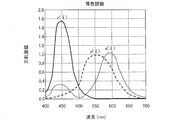
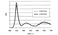
- 6 is a graph showing a color matching function converted into. It is a block diagram which shows schematic structure of the principal part of the display apparatus in the display system concerning the other form of implementation of this invention. It is a graph which shows the emission spectrum of the backlight at the time of 2D display and 3D display in the display system shown in FIG.
- 6 is a graph showing emission spectra LB ( ⁇ ), LG ( ⁇ ), and LR ( ⁇ ) of backlights of RGB LEDs when the maximum emission intensity is normalized as 1.
- the display system according to the present embodiment is a 3D (Dimension) stereoscopic image display system (stereoscopic image display system), and is capable of displaying an image for 3D display (see FIGS. 2 and 4). a) and (b)), and glasses (hereinafter, referred to as “3D glasses”) 200 for stereoscopically displaying a 3D display image displayed on the display device 100 (optical member, FIG. 2A and FIG. 4A). ) And (b)).
- the 3D display image refers to an image in which a left-eye image and a right-eye image are mixed.
- the display system displays the left-eye image and the right-eye image on the same surface on the display device 100, and the 3D glasses 200 separate the left-eye image and the right-eye image into a stereoscopic view. That is, the display system reproduces a stereoscopic image using the parallax of both eyes by visually recognizing the left eye image with the left eye and the right eye image with the right eye through the 3D glasses 200.
- the display device 100 used in the present embodiment can perform 2D display, and in this case, the 3D glasses 200 are not used.
- the 3D display the left eye image is displayed in the first display area and the right eye image is displayed in the second display area, so that different lights reach the left and right eyes, whereas in the 2D display, By displaying the same image in the entire display area, the same light reaches the left and right eyes.
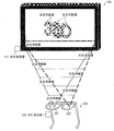
- FIG. 2 is a diagram showing the display principle of the shutter glasses type display system.
- a stereoscopic image signal using the parallax of the left and right eyes is input to the display device 100 from the outside.
- the display device 100 alternately displays the left-eye image and the right-eye image for each frame (time-division display, interlaced display) as shown in FIG.
- the shutter glasses are used as the 3D glasses 200.
- the shutter glasses include a shutter mechanism (opening / closing mechanism) in each of the left eye part 201 and the right eye part 202.
- the shutter glasses alternately open and close the left eye part 201 and the right eye part 202 in synchronization with each frame of the display device 100.
- the shutter glasses open the shutter of the left eye portion 201 and close the shutter of the right eye portion 202, so that the right eye image is displayed on the display screen of the display device 100.
- the shutter of the right eye unit 202 is opened and the shutter of the left eye unit 201 is closed.
- the image displayed on the display screen of the display device 100 is visually recognized as a stereoscopic image by visually recognizing the left-eye image with the left eye and the right-eye image with the right eye. Can do.
- a liquid crystal shutter can be used as the shutter glasses.
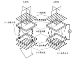
- FIG. 3 shows the principle of a typical TN type liquid crystal shutter.
- the liquid crystal shutter used for the liquid crystal shutter glasses generally has two polarizing plates 212 on both front and back surfaces of a liquid crystal cell in which liquid crystal molecules 211 are sealed between a pair of base materials (not shown) having translucency. So-called sandwich structure.
- a liquid crystal layer in which the arrangement of liquid crystal molecules 211 is twisted by 90 degrees is sandwiched between two polarizing plates 212.
- the liquid crystal cell is provided with a pair of transparent electrodes 213 and 214 for applying an electric field to the liquid crystal layer. Light is transmitted and voltage is applied when no voltage is applied between the pair of transparent electrodes 213 and 214. Then, the light is blocked, and the liquid crystal layer functions as a shutter.
- the synchronization between the display device 100 and the shutter glasses is performed by receiving a signal from the infrared transmitter 101 provided in the display device 100 with an infrared receiver 203 provided in the shutter glasses.
- an LED Light Emitting Diode
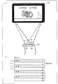
- FIG. 4A is a diagram showing the display principle of the display system of the polarized glasses system
- FIG. 4B is a display of the left-eye image in the region 111 indicated by a frame in FIG. 4A. It is a figure which shows the polarization direction in the area
- the left-eye image and the right-eye image displayed on the display device 100 are linearly polarized light whose polarization directions form an angle of 90 degrees with each other. . That is, in the stereoscopic video display system using the polarized glasses method, the display device 100 displays images whose polarization directions are different by 90 degrees in the display area 111a for the left-eye image and the display area 111b for the right-eye image.
- Polarized glasses transmit polarized light whose polarization directions differ by 90 degrees on the left and right.
- FIG. 5 is a diagram showing an example of a schematic configuration of a main part of a display system using a polarized glasses method.
- a liquid crystal display device shown in FIG. 5 can be used as the display device 100 used in the display system using the polarized glasses method.
- a liquid crystal display device shown in FIG. 5 a liquid crystal layer 140 is sandwiched between an active matrix substrate 120 and a counter substrate 130, and stripe-shaped left eye pixel electrodes 121 and right eye pixel electrodes 122 are alternately arranged on the active matrix substrate 120. Is provided. Further, a polarizing layer 131 and a retardation layer 132 are provided on the counter substrate 130 on the liquid crystal layer 140 side so that the polarization directions of the left-eye image light and the right-eye image light are different from each other.
- stripe-shaped left-eye phase difference regions and right-eye phase difference regions are alternately arranged in the phase difference layer 132, so that the left-eye image display region 111 a and the right-eye image are displayed.
- a display area 111b is provided.
- the light from the left-eye pixel that is configured by the facing portion of the left-eye pixel electrode 121 and the counter electrode 133 in the counter substrate 130 passes through the polarizing layer 131 and is changed to linearly polarized light. And pass through the phase difference region for the left eye.
- the light from the right-eye pixel constituted by the facing portion of the right-eye pixel electrode 122 and the counter electrode 133 on the counter substrate 130 passes through the polarizing layer 131 and is detected as linearly polarized light, and the right-eye phase difference is detected. Go through the area. Thereby, the left-eye image light and the right-eye image light are emitted from the left-eye phase difference region and the right-eye phase difference region, respectively.
- the polarized glasses have a left-eye polarizing plate 221 corresponding to the polarization direction of the left-eye image light emitted from the display device 100 and a right-eye polarizing plate 222 corresponding to the polarization direction of the right-eye image light, and are polarized for the left eye.
- a left-eye phase modulator 231 is provided on the light incident side of the plate 221, and a right-eye phase modulator 232 is provided on the light incident side of the right-eye polarizing plate.
- the polarization directions of the left-eye image light and the right-eye image light are different (orthogonal in this embodiment), and the polarization axis of the left-eye polarizing plate 221 and the left-eye image light
- the polarization direction is aligned with the polarization axis of the right-eye polarizing plate 222 and the polarization direction of the right-eye image light
- the left-eye image light is observed only by the left eye
- the right-eye image light is observed only by the right eye.
- the image displayed on the display apparatus 100 can be recognized as a stereoscopic image.
- liquid crystal display device capable of switching between 2D display and 3D display will be described as an example of the display device 100, and shutter glasses will be described as an example of the 3D glasses 200. The case of using is described as an example.
- the left-eye image and the right-eye image are alternately switched and displayed for each frame by a frame sequential method (time division drive method), thereby displaying the image in a three-dimensional manner.
- the display mode for performing 2D display is referred to as “2D mode” (2D display mode)
- the display mode for performing 3D display is referred to as “3D mode” (3D display mode).
- switching between 2D display and 3D display may be performed by inputting a switch button (not shown) for switching between 2D display and 3D display provided on the controller or the display device main body, and 2D / 3D display together with video signals from the outside.
- the 3D mode switching signal is input, the 2D display and the 3D display may be switched by the 2D / 3D mode switching signal.
- the input video signal includes image data for 3D display. In such a case, it is possible to automatically switch between 2D display and 3D display.
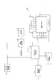
- FIG. 1 is a block diagram showing a schematic configuration of a main part of a display device in the display system according to the present embodiment.
- a display device 100 used in the present embodiment is a liquid crystal display device, and as shown in FIG. 1, a liquid crystal panel 1, a backlight 2, a data driver 11 as a drive circuit for driving the liquid crystal panel 1, and a gate.
- a driver 12, a backlight driving unit 13, a timing control unit 14, a 2D / 3D switching processing unit 15, an image processing unit 16, a storage unit 17, and a 3D glasses driving unit 18 are provided.
- the liquid crystal panel 1 has a structure in which a liquid crystal layer is sandwiched between an array substrate such as a TFT (thin film transistor) substrate and a counter substrate.
- the liquid crystal panel 1 has a plurality of pixels, and, for example, polarizing plates are attached to the front and back substrate surfaces.
- various known liquid crystal panels can be used. Therefore, description and illustration regarding each substrate configuration of the liquid crystal panel 1 are omitted here.
- the liquid crystal panel 1 modulates the backlight light emitted from the backlight 2 based on the drive voltage supplied from the data driver 11 in accordance with the drive signal supplied from the gate driver 12, thereby converting the image signal into a video signal. Based video display.
- the backlight 2 is an illumination member that is provided on the back side (the side opposite to the display surface) of the liquid crystal panel 1 and irradiates the liquid crystal panel 1 with light.
- the backlight for example, an LED backlight system using LEDs as light emitting elements (light sources) is used.
- the data driver 11 converts the received data (data obtained by performing predetermined processing on the video signal) into a voltage value based on the timing signal from the timing control unit 14, and applies a driving voltage to each pixel of the liquid crystal panel 1.
- the gate driver 12 sequentially turns on (ON) / off (OFF) the gates of switching elements (not shown) such as TFTs provided in the liquid crystal panel 1 based on the timing signal from the timing controller 14. .
- a desired voltage corresponding to the video signal is applied to each pixel of the liquid crystal panel 1.
- the backlight drive unit 13 is a drive circuit for driving the backlight 2, and controls the lighting of the LEDs constituting the backlight 2 based on the timing signal from the timing control unit 14.
- the backlight drive unit 13 performs lighting drive control on the LEDs of the backlight 2 so as to perform backlight scanning for performing 3D display.
- the timing control unit 14 generates a timing control signal for controlling the driving timing of driving circuits such as the data driver 11, the gate driver 12, and the backlight driving unit 13.
- the timing control unit 14 controls the drive timing of the data driver 11 and the gate driver 12, and transfers video data from the image processing unit 16 to these drivers. Further, the scanning of the backlight 2 and the driving timing of the 3D glasses 200 during 3D display are controlled.
- the left eye 201 and the right eye 202 of the shutter glasses are provided with shutters as described above, and each shutter is driven independently.
- the shutter is driven by a driving signal from the 3D glasses driving unit 18.
- the 3D glasses driving unit 18 controls the opening and closing of the shutter of the 3D glasses 200 including the shutter glasses used in the 3D mode.
- the 3D glasses driving unit 18 outputs a driving signal to the 3D glasses 200 based on the timing signal from the timing control unit 14.
- the infrared transmitter 101 and the infrared receiver 203 are used, and a drive signal is output by infrared rays.
- the 2D / 3D switching processing unit 15 generates and outputs various instruction signals for switching between the 2D mode and the 3D mode.
- the 2D / 3D switching processing unit 15 responds to a 2D / 3D mode switching signal such as a 2D / 3D mode switching signal by an observer or a 2D / 3D mode switching signal automatically transmitted in synchronization with a video signal.
- the image processing unit 16 generates and outputs an instruction signal for performing image processing corresponding to each display mode, and changes the lighting timing of the backlight 2 to a timing corresponding to each display mode.
- An instruction signal is output to the timing control unit 14.
- the image processing unit 16 Based on the instruction signal sent from the 2D / 3D switching processing unit 15, the image processing unit 16 performs image processing corresponding to each display mode on the input video signal, and the image processing is performed.
- the video signal is supplied to the timing control unit 14.
- the image processing unit 16 performs image processing such as color correction, tone correction, gradation correction, noise removal, and the like on the input video signal as necessary. Then, various video signals for 3D display such as frame packing and side-by-side are converted into frame sequential video signals.
- input gradation video input signal gradation
- output gradation video output signal gradation
- LUT lookup table, conversion table
- the LUTL is associated with an output gradation (correction gradation) corresponding to the transmittance spectrum (spectral characteristics) of the 3D glasses 200 with respect to the input gradation of the video signal input to the liquid crystal panel 1.
- gradations between input gradations shown in the LUT are interpolated from output gradations obtained by the LUT from previous and subsequent input gradations to determine output gradations. .
- the size of the LUT can be reduced.
- a magnetic disk device such as an HDD or an EEPROM which is a semiconductor memory, which keeps data even when the power is turned off, is preferably used.
- the image processing unit 16 When the image processing unit 16 receives an instruction signal corresponding to the 3D mode from the 2D / 3D switching processing unit 15, the image processing unit 16 applies to the input video signal in addition to image processing such as color correction, tone correction, and noise removal. Then, gradation conversion with reference to the LUT stored in the storage unit 17 is performed. The gradation correction referring to the LUT stored in the storage unit 17 is performed only in the 3D mode and not in the 2D mode. In the 2D mode and the 3D mode, image processing such as color correction, color tone correction, and noise removal is performed as necessary. The gradation conversion will be described in detail later.
- Examples of the video signal supplied to the image processing unit 16 include a received signal (broadcast wave signal) from a tuner (not shown), a video signal from a VTR (video tape recorder) device, various players, and the like.
- FIG. 6 shows a timing chart in the 2D mode
- FIG. 7 shows a timing chart in the 3D mode.
- a video signal (data) is written to the liquid crystal panel 1 from top to bottom for each frame, and the backlight 2 is sequentially switched from top to bottom for each frame accordingly.
- the backlight scan is performed so that the light is turned on each time and is turned off sequentially from the top to the bottom after a certain period.
- the video signals (data) of the right eye and the left eye are written to the liquid crystal panel 1 twice, and the backlight 2 starts from the top in accordance with each second writing.
- the backlight scan is performed so that the light is sequentially turned on and turned off after a certain period. That is, in the 3D mode, the backlight 2 is turned on every other frame.
- the 3D glasses 200 including shutter glasses are driven by the 3D glasses driving unit 18 in synchronization with switching between the first video signal writing and the second video signal writing in the same frame. Specifically, the right-eye shutter is closed and the left-eye shutter is opened until the first writing of the right-eye video signal of the same frame is completed, and from the second writing start of the right-eye video signal of the same frame. The left-eye shutter is closed and the right-eye shutter is opened.
- 3D display that is, stereoscopic viewing is enabled.
- FIG. 8 is a graph showing the chromaticity shift of the white chromaticity point in the CIE chromaticity coordinates defined by the CIE (International Institute of Lighting).
- Such a problem is caused, for example, by the fact that the transmittance spectrum of 3D glasses differs depending on the wavelength as shown in FIG. Note that the transmittance spectrum of the 3D glasses depends on the transmittance spectrum of the polarizing element when the 3D glasses are of the polarization type. On the other hand, when the 3D glasses are a liquid crystal shutter system, it depends on the transmittance spectrum of the polarizing element and the liquid crystal layer.
- ⁇ Color shift correction method> Therefore, in this embodiment, in the 3D mode, the color shift of the 3D glasses 200 is taken into consideration, and the color of the image displayed on the display device 100 is set so that a correct color is obtained after passing through the 3D glasses 200. change.
- the color of the image displayed on the display device 100 is changed so that the chromaticity of white when passing through the 3D glasses 200 matches the chromaticity of standard white (reference white).
- standard white indicates the white chromaticity of the display device 100 in the 2D mode in which the 3D glasses 200 are not used (that is, in a state without color shift).
- the display system is a TV (television) system
- standard white indicates the white chromaticity of the TV receiver in the 2D mode in which the 3D glasses 200 are not used.
- the color of the image displayed on the display device 100 is stored in the storage unit 17 in the 3D mode as described above so that a correct color can be obtained after passing through the 3D glasses 200.
- Gradation conversion using an LUT in which an output gradation (corrected gradation) corresponding to a transmittance spectrum (spectral characteristic) of the 3D glasses 200 with respect to an input gradation of a video signal input to the liquid crystal panel 1 is associated (Tone correction).
- the gradation data of the video signal input to the liquid crystal panel 1 is corrected (gradation conversion) in order to correct the color shift.
- gradation conversion gradation conversion
- FIG. 9 is a graph showing the transmittance spectrum TG ( ⁇ ) of the liquid crystal shutter negative when the liquid crystal shutter glasses are used as the 3D glasses 200 as described above.
- FIG. 10 is a graph showing the emission spectra DR ( ⁇ ), DG ( ⁇ ), and DB ( ⁇ ) of the display device 100.
- FIG. 11 shows the spectrum tristimulus values r ( ⁇ ), g ( ⁇ ), and b ( ⁇ ) of red (R), green (G), and blue (G) as virtual spectrum tristimulus values x in the XYZ system.
- the three primary colors are R (700 nm) and G (546). .1 nm) and B (435.8 nm), the tristimulus values necessary to make all the single light colors in visible light wavelengths (380 nm to 780 nm) uniform.
- XR, YR, and ZR the tristimulus values of light when the display device 100 displays red in the 2D mode in which the 3D glasses 200 are not used (that is, without color shift)
- XR, YR , ZR is the following formula:
- XR RDR ( ⁇ ) ⁇ x ( ⁇ ) ⁇ d ⁇
- YR ⁇ DR ( ⁇ ) ⁇ y ( ⁇ ) ⁇ d ⁇
- ZR ⁇ DR ( ⁇ ) ⁇ z ( ⁇ ) ⁇ d ⁇
- XR RDR ( ⁇ ) ⁇ x ( ⁇ ) ⁇ d ⁇
- YR ⁇ DR ( ⁇ ) ⁇ y ( ⁇ ) ⁇ d ⁇
- ZR ⁇ DR ( ⁇ ) ⁇ z ( ⁇ ) ⁇ d ⁇
- XR RDR ( ⁇ ) ⁇ x ( ⁇ ) ⁇ d ⁇
- YR ⁇ DR ( ⁇ ) ⁇ y ( ⁇ ) ⁇ d ⁇
- ZR ⁇ DR
- DR ( ⁇ ), DG ( ⁇ ), and DB ( ⁇ ) indicate the emission spectrum of the display device 100.
- x ( ⁇ ), y ( ⁇ ), and z ( ⁇ ) indicate color matching functions (the CIE priming amount necessary to equalize spectral colors) for each wavelength, as defined in JIS Z8701.
- D ⁇ represents a change amount (movement amount) of wavelength
- the light tristimulus values in the display device 100 are XW, YW, and ZW, respectively.
- XB ′, YB ′, and ZB ′ are XB ′, YB ′, and ZB ′, respectively.
- YB ′ ⁇ TG ( ⁇ ) ⁇ DB ( ⁇ ) ⁇ y ( ⁇ ) ⁇ d ⁇
- ZB ′ ⁇ TG ( ⁇ ) ⁇ DB ( ⁇ ) ⁇ z ( ⁇ ) ⁇ d ⁇
- YB ′ ⁇ TG ( ⁇ ) ⁇ DB ( ⁇ ) ⁇ y ( ⁇ ) ⁇ d ⁇
- ZB ′ ⁇ TG ( ⁇ ) ⁇ DB ( ⁇ )
- XW ′ XR ′ + XB ′ + XG ′
- YW ' YR' + YB '+ YG'
- ZW ' ZR' + ZB '+ ZG'
- (xw ′′, yw ′′) (xw, yw), that is, as described above, after passing through the 3D glasses 200 when the display device 100 displays white in the 3D mode.
- the ratio r, g, b of R, G, B of the display device 100 so that the chromaticity of light has the same value as the chromaticity of light in the display device 100 when the display device 100 displays white in the 2D mode. Is adjusted to determine the output gradation (correction gradation) in the 3D mode.
- the display device 100 is 255 for R, G, and B in the 2D mode.
- An image is displayed with gradation, but in 3D display, B remains at 255 gradation, R is compressed to 249 gradation, and G is compressed to 225 gradation, and the image is displayed.
- the transmittance spectrum of the 3D glasses 200 shown in FIG. 9 has low transmittance in the short wavelength (blue) region and the long wavelength (red) region. For this reason, as described above, B having the lowest transmittance is kept at 255 gradations, G having the highest transmittance is compressed to 225 gradations, and R between them is changed to the gradation between B and G. By doing so, the above-described chromaticity shift depending on the transmittance spectrum of the 3D glasses 200 can be eliminated.
- the ratios r, g, and b of the R, G, and B gradations were calculated and experimented based on the calculated ratios.
- the gradation limit (correction gradation) in the 3D mode varies depending on the transmittance spectrum of the 3D glasses 200.
- the relationship between the input gradation and the output gradation (corrected gradation) corresponding to the transmittance spectrum of the 3D glasses 200 is shown in advance in the storage unit 17.
- the change of the color of the image displayed on the display device 100 is electrically controlled. For this reason, unlike the case where a physical correction means (filter) is provided in the shutter glasses as in Patent Document 1, the manufacturing cost can be suppressed. Further, according to the present embodiment, unlike in Patent Document 1, no physical correction means (filter) that causes a decrease in transmittance is provided in the shutter glasses, so that the transmittance of the 3D glasses 200 is not decreased. A bright 3D image can be obtained.
- the present embodiment it is possible to provide a stereoscopic image display system and a display method that can obtain a stereoscopic image of a correct color without lowering the transmittance of the 3D glasses 200 at low cost.
- a shutter-type display system using liquid crystal shutter glasses as the 3D glasses 200 and using a liquid crystal display device as the display device 100 is used.
- the present embodiment is not limited to this.
- the display system may be a polarization type display system using polarized glasses for the 3D glasses 200 as described above.
- the display system that switches between 2D display and 3D display has been described as an example.
- the display system need only be capable of displaying a stereoscopic image, and may be a display system dedicated to 3D display. That is, the display device 100 performs 2D display at the time of manufacture, and the white color when passing through the 3D glasses 200 with the white chromaticity of the display device 100 at this time as the chromaticity of standard white (reference white). If an LUT indicating the relationship between the input gradation and the output gradation is created in advance and stored in the storage unit 17 so that the degree matches the chromaticity of the standard white (reference white), 3D can be used in actual use. It can be used as a dedicated display device, and it is not always necessary to switch between 2D display and 3D display.
- the display device 100 includes the storage unit 17 in which the LUT is stored, and the image processing unit 16 refers to the LUT stored in the storage unit 17 (storage means) to determine the input floor.
- the storage unit 17 that stores the LUT may be provided outside the display device 100 as a storage device.
- the case where the 3D glasses 200 are used as the optical member for stereoscopically displaying the 3D display image displayed on the display device 100 has been described as an example.
- the optical member only needs to allow the observer to stereoscopically view the 3D display image displayed on the display device 100, and transmits the light transmitted through the display device 100 during 3D display.
- the shape and type are not particularly limited.
- the optical member may be provided so as to be selectively usable during 3D display.
- the optical member may be provided detachably with respect to the observer like 3D glasses, or may be provided detachably with respect to the display device 100. Further, it may be provided between the observer and the display device 100 so as to be selectively usable.
- the degree of freedom in designing the optical member can be increased.
- the gradation data of the video signal input to the liquid crystal panel 1 to correct the color shift is subjected to color correction (gradation conversion) using the ⁇ (gamma) constant in the image processing unit 16. )
- the color of the image displayed on the display device 100 in the 3D mode is converted by converting the input gradation in accordance with the transmittance spectrum (spectral characteristics) of the 3D glasses 200 in the 3D mode.
- the case of changing was described as an example.
- the auxiliary light source when display is performed using the backlight 2 such as when the display device 100 is a liquid crystal display device, the auxiliary light source is used, and the emission spectrum of the backlight 2 is set in the 2D mode.
- the color of the image displayed on the display device 100 in the 3D mode is changed by changing between the 3D mode and the 3D mode will be described.
- a liquid crystal display device that includes the 2D / 3D switching processing unit 15 and can perform switching between 2D display and 3D display will be described as an example of the display device 100.
- a case where shutter glasses are used as an example of the 3D glasses 200 will be described as an example.
- FIG. 12 is a block diagram showing a schematic configuration of a main part of the display device 100 in the display system according to the present embodiment.
- the display device 100 used in the present embodiment is a liquid crystal display device, and as shown in FIG. 12, a liquid crystal panel 1, a backlight 2, a data driver 11 as a drive circuit for driving the liquid crystal panel 1, and a gate.
- a driver 12, a backlight driving unit 13, a timing control unit 14, a 2D / 3D switching processing unit 15, an image processing unit 16, and a 3D glasses driving unit 18 are provided.
- the backlight 2 used in the present embodiment includes a plurality of LEDs 20 (see FIGS. 17 and 20) as light sources.
- the LED 20 is a white LED and is used for 2D display (hereinafter referred to as “2D display LED”) 21 (see FIGS. 18, 19, 21, and 22) and 3D.
- 2D display LED hereinafter referred to as “2D display LED”
- 3D 3D
- an auxiliary light source LED hereinafter referred to as “correction LED”; see FIGS. 18, 19, 21, and 22
- the configuration of the backlight 2 will be described in detail later.
- the image processing unit 16 performs image processing corresponding to each display mode on the input video signal based on the instruction signal sent from the 2D / 3D switching processing unit 15, The video signal subjected to the image processing is supplied to the timing control unit 14.
- the image processing unit 16 performs image processing such as color correction, tone correction, gradation correction, noise removal, and the like on the input video signal as necessary. Then, various video signals for 3D display such as frame packing and side-by-side are converted into frame sequential video signals.
- gradation conversion referring to the LUT stored in the storage unit 17 as described in the first embodiment is not performed. Instead, in the present embodiment, the backlight driver 13 turns on the correction LED 22 in the 3D mode and turns off the correction LED 22 in the 2D mode.
- the driving method of the 2D display LED 21 in the backlight driving unit 13 is the same as that in the first embodiment, and the 2D display LED 21 is driven and controlled at the driving timing shown in FIGS. 6 and 7, for example.
- the correction LED 22 is turned on only in the 3D mode, is driven and controlled in synchronization with the 2D display LED 21 in the 3D mode, and is turned off in the 2D mode.
- FIG. 13 is a graph showing an emission spectrum of the backlight 2 during 2D display and 3D display in the display system according to the present embodiment.
- the correction LED 22 is used as an auxiliary light source, and the emission spectrum of the backlight 2 is changed between 2D mode and 3D mode as shown in FIG.
- the 3D mode the color of the image displayed on the display device 100 is changed so that a correct color can be obtained after passing through the 3D glasses 200.
- the emission spectrum of the auxiliary light source is determined according to the transmittance spectrum of the 3D glasses 200 so that a correct color can be obtained after passing through the 3D glasses 200 in the 3D mode.
- a white LED is used as the 2D display LED 21 as the light source of the backlight 2.
- a purple LED is used as the correction LED 22.
- the transmittance spectrum of the 3D glasses 200 shown in FIG. 9 has low transmittance in the short wavelength (blue) region and the long wavelength (red) region. Therefore, by using a light source (LED) that emits light in a short wavelength (blue) region and a long wavelength (red) region with low transmittance as a correction light source (correction LED), the above-described 3D glasses 200 The chromaticity shift depending on the transmittance spectrum can be eliminated.
- LED light source
- the white LED can be obtained, for example, by coating a blue LED (B-LED) with a green phosphor and a red phosphor. Moreover, you may form white LED by combining blue LED and yellow fluorescent substance. A purple LED can be obtained by applying a red phosphor to a B-LED.
- a well-known fluorescent substance can be used for the fluorescent substance of each color, and the kind will not be limited if the desired luminescent color according to the transmittance
- the formation method of LED of each color is not limited.
- the white LED for example, an LED (white light emitting element) that emits white light from one LED chip may be used as described above, and LED chips of R, G, and B colors are molded into one package. You may use LED.
- the transmittance spectrum of the 3D glasses 200 varies depending on the configuration of the 3D glasses 200. Therefore, when the 3D glasses 200 having low blue and red transmittances are used as described above, a purple LED that emits blue and red light (that is, purple light) is used as the correction LED 22. If the transmittance spectrum of the 3D glasses 200 changes, it is necessary to change the type (emission color, emission spectrum) of the LED used as the correction LED 22 in accordance with the transmittance spectrum of the 3D glasses 200.
- the emission spectrum of R, G, B of the correction LED 22 is determined by the intensity ratios r, g, b of the R, G, B of the correction LED 22.
- FIG. 14 is a graph showing the transmittance spectrum TP ( ⁇ ) of the liquid crystal panel 1 when a liquid crystal display device is used as the display device 100.
- FIG. 15 is a graph showing an emission spectrum LW ( ⁇ ) of the backlight 2 (BL) by the LED 21 for 2D display.
- FIG. 16 is a graph showing emission spectra LB ( ⁇ ), LG ( ⁇ ), and LR ( ⁇ ) of the backlight 2 (BL) by the correction LED 22 when the maximum emission intensity is normalized as 1.
- xw ′ XW ′ / (XW ′ + YW ′ + ZW ′)
- yw ′ YW ′ / (XW ′ + YW ′ + ZW ′)
- the correction LED 22 is lit with the intensity ratios r, g, and b of R, G, B, and the 3D glasses 200 when the display device 100 displays white color.
- the correction LED 22 is lit with the intensity ratios r, g, and b of R, G, B, and the 3D glasses 200 when the display device 100 displays white is displayed.
- the intensity ratios r, g of R, G, B of the correction LED 22 so that the chromaticity (xw ′′, yw ′′) becomes a predetermined chromaticity (chromaticity point). , B are determined (note that zw ′′ 1 ⁇ xw ′′ ⁇ yw ′′).
- (xw ′′, yw ′′) (xw, yw), that is, as described above, in the 3D mode, in addition to the 2D display LED 21, the correction LED 22 is set to R, G, B.
- the display device 100 displays white in intensity ratios r, g, and b
- the chromaticity of light after passing through the 3D glasses 200 is white by the 2D display LED 21 in the 2D mode.
- Intensity ratios r, g, and b of R, G, and B of correction LED 22 are determined so as to have the same value as the chromaticity of light in display device 100 when displayed.
- the transmittance spectrum of the correction LED 22 on the backlight 2 is (r ⁇ LR ( ⁇ ) + g ⁇ LG ( ⁇ ) + b ⁇ LB ( ⁇ )), which is a single LED as described above. Or may be realized by a plurality of LEDs.
- the display device 100 when a liquid crystal display device is used as the display device 100, the display device 100 is configured by laminating the liquid crystal panel 1 and the backlight 2.
- LED backlights using LEDs as light sources can be roughly classified into direct type and edge light type.
- FIG. 17 is an exploded perspective view showing a schematic configuration of a main part of a liquid crystal display device having a direct-type LED backlight as the backlight 2.
- FIGS. 18 and 19 are plan views showing examples of the arrangement of the 2D display LED 21 and the correction LED 22 when a direct type LED backlight is used as the backlight 2, respectively.
- the backlight 2 composed of a direct type LED backlight has a plurality of LEDs 20 arranged in a plane, and an optical sheet such as a diffusion plate, a diffusion sheet, a lens sheet, and a polarization reflection sheet is disposed above the backlight 20.
- a class 30 is arranged.
- FIG. 18 shows an example in which the 2D display LED 21 and the correction LED 22 are integrally formed at a ratio of 1: 1 and arranged uniformly.
- the 2D display LED 21 and the correction LED 22 are driven independently of each other.
- the arrangement of the 2D display LED 21 and the correction LED 22 is not limited to this.
- the correction LEDs 22 may be arranged only in a part of the surface of the backlight 2, particularly in the central part. In this case, although the color gradually changes from the portion where the correction LED 22 is disposed to the portion where the correction LED 22 is not disposed, an increase in power and cost due to the correction LED 22 can be suppressed.
- FIG. 20 is an exploded perspective view showing a schematic configuration of a main part of a liquid crystal display device having an edge light type LED backlight as the backlight 2.
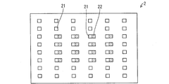
- 21 and 22 are plan views showing examples of arrangement of the 2D display LED 21 and the correction LED 22 when an edge light type LED backlight is used as the backlight 2, respectively.
- the edge light type backlight 2 includes a light guide plate 41 and a plurality of LEDs 20 provided on an end surface (edge portion) of the light guide plate 41, and a diffusion sheet is provided on the light guide plate 41.
- optical sheets 30 such as a lens sheet and a polarization reflection sheet are laminated.
- the 2D display LED 21 and the correction LED 22 are 1: 1, 2: 1, 3: 1, etc., as shown in FIG. It is desirable that they are arranged in the same distribution in the same plane in the periphery of the light guide plate.
- FIG. 21 shows an example in which the 2D display LED 21 and the correction LED 22 are integrally formed at a ratio of 1: 1 and are uniformly arranged on the two opposite end faces (edge portions) of the light guide plate 41. .
- the 2D display LED 21 and the correction LED 22 are driven independently of each other.
- the correction LED 22 is connected to a part of the surface of the backlight 2, particularly the light guide plate 41. You may arrange only in the center part of two opposing end surfaces (edge part). Also in this case, although the color changes gently from the portion where the correction LED 22 is disposed to the portion where the correction LED 22 is not disposed, an increase in power and cost due to the correction LED 22 can be suppressed.
- the 2D display LED 21 is lit during 2D display, and the correction LED 22 is lit in addition to the 2D display LED 21 during 3D display, thereby displaying on the display device 100.
- the color change of the displayed image is electrically controlled. For this reason, also in the present embodiment, as in the first embodiment, it is possible to reduce the manufacturing cost and to obtain a bright 3D image without reducing the transmittance of the 3D glasses 200.
- the gradation of the display device 100 is not limited, gradation expression according to gradation data in the video signal can be maintained.
- red LED red LED
- green LED G-LED
- blue LED B-LED
- LED RGB-LED
- the output ratio is controlled, so that the emission spectrum of the backlight 2 is changed between the 2D mode and the 3D mode, thereby being displayed on the display device 100 in the 3D mode. A case where the color of the image is changed will be described.
- a liquid crystal display device capable of switching between 2D display and 3D display will be described as an example of the display device 100, and shutter glasses will be used as an example of the 3D glasses 200. An example will be described.
- the block diagram itself showing the schematic configuration of the main part of the display device 100 in the display system according to the present embodiment is the same as the block diagram shown in FIG. Therefore, in the present embodiment, illustration of the block diagram is omitted.
- the backlight 2 used in the present embodiment includes the three types of RGB LEDs as the LEDs 20 as described above.
- the schematic configuration of the backlight 2 is as shown in FIGS. 17 and 20.
- the image processing unit 16 performs image processing corresponding to each display mode on the input video signal based on the instruction signal sent from the 2D / 3D switching processing unit 15, The video signal subjected to the image processing is supplied to the timing control unit 14.
- the image processing unit 16 performs image processing such as color correction, tone correction, gradation correction, noise removal, and the like on the input video signal as necessary. Then, various video signals for 3D display such as frame packing and side-by-side are converted into frame sequential video signals.
- the backlight drive unit 13 changes the RGB light emission ratio (output ratio) of the LED 20 between the 2D mode and the 3D mode.
- the backlight drive unit 13 stores an RGB output intensity ratio for 2D mode and an RGB output intensity ratio (output ratio) for 3D mode in advance.
- the backlight drive unit 13 controls the output of each LED 20 in the backlight 2 at a previously stored output ratio depending on the display mode, that is, whether the mode is the 2D mode or the 3D mode.
- the driving method of the RGB LEDs in the backlight driving unit 13 is the same as that in the first embodiment, and these RGB LEDs are driven and controlled at the driving timings shown in FIGS. 6 and 7, for example.
- FIG. 23 is a graph showing an emission spectrum of the backlight 2 during 2D display and 3D display in the display system according to the present embodiment.
- the color of the backlight 2 can be freely changed by the RGB light emission ratio.
- the emission spectrum of the backlight 2 is shown in, for example, FIG. 23 by using the LED 20 as the LED 20 and changing the output ratio of the LEDs of the respective colors. As described above, it is changed between the 2D mode and the 3D mode.
- the output ratio of the LEDs of the respective colors is determined in accordance with the transmittance spectrum of the 3D glasses 200 so that a correct color can be obtained after passing through the 3D glasses 200 in the 3D mode.
- the transmittance spectrum of the 3D glasses 200 shown in FIG. 9 has low transmittance in the short wavelength (blue) region and the long wavelength (red) region. For this reason, it depends on the transmittance spectrum of the 3D glasses 200 described above by increasing the output of the blue LED and the red LED that emit light in the short wavelength (blue) region and the long wavelength (red) region with low transmittance. It is possible to eliminate the chromaticity shift.
- the output ratio of the R, G, and B LEDs is determined by the intensity ratios r, g, and b of R, G, and B.
- FIG. 24 is a graph showing emission spectra LB ( ⁇ ), LG ( ⁇ ), and LR ( ⁇ ) of the backlight 2 (BL) by RGB LEDs when the maximum emission intensity is normalized as 1.
- FIG. 25 is a graph showing an emission spectrum LW ( ⁇ ) of the backlight 2 by RGB LEDs at the time of 2D display (in this embodiment, at the time of 2D mode).
- the emission spectrum of the RGB LEDs is set to LW ( ⁇ ) so that the display device 100 displays with a predetermined chromaticity.
- XW ′ ⁇ TG ( ⁇ ) ⁇ TP ( ⁇ ) ⁇ LW ( ⁇ ) ⁇ x ( ⁇ ) ⁇ d ⁇
- YW ′ ⁇ TG ( ⁇ ) ⁇ TP ( ⁇ ) ⁇ LW ( ⁇ ) ⁇ y ( ⁇ ) ⁇ d ⁇
- ZW ′ ⁇ TG ( ⁇ ) ⁇ TP ( ⁇ ) ⁇ LW ( ⁇ ) ⁇ z ( ⁇ ) ⁇ d ⁇
- XW ′ ⁇ TG ( ⁇ ) ⁇ TP ( ⁇ ) ⁇ LW ( ⁇ ) ⁇ ⁇ z ( ⁇ ) ⁇ d ⁇
- the intensity ratios r, g of R, G, B of the correction LED 22 so that the chromaticity (xw ′′, yw ′′) becomes a predetermined chromaticity (chromaticity point). , B are determined (note that zw ′′ 1 ⁇ xw ′′ ⁇ yw ′′).
- RGB LEDs are connected to R, G, and B intensity ratios r, g, and b.
- R, G, and B intensity ratios r, g, and b of RGB LEDs in the 3D mode are determined so as to have the same value as the light chromaticity in the display device 100.
- the color of the image displayed on the display device 100 can be changed by changing the output ratio of the RGB LEDs in accordance with the transmittance spectrum of the 3D glasses 200 during 3D display. Control changes electrically. For this reason, also in the present embodiment, as in the first embodiment, it is possible to reduce the manufacturing cost and to obtain a bright 3D image without reducing the transmittance of the 3D glasses 200.
- the structure can be further reduced.
- the gradation of the display device 100 is not limited, the gradation expression according to the gradation data in the video signal can be maintained.
- the display system that switches between 2D display and 3D display has been described as an example, as in the first and second embodiments.
- the present embodiment is not limited to this. . That is, the display device 100 performs the 2D display as described above at the time of manufacture, and when the white chromaticity of the display device 100 at this time is set as the standard white (reference white) chromaticity and passes through the 3D glasses 200.
- the display device 100 performs the 2D display as described above at the time of manufacture, and when the white chromaticity of the display device 100 at this time is set as the standard white (reference white) chromaticity and passes through the 3D glasses 200.
- the intensity ratio (output ratio) of RGB output for 3D mode in the backlight drive unit 13 in advance so that the white chromaticity matches the chromaticity of standard white (reference white).
- it can be used as a display device dedicated to 3D, and it is not always necessary to switch between 2D display and 3D display.
- a display system is capable of stereoscopically displaying a display device capable of displaying an image for 3D display and the 3D display image displayed on the display device.
- the display device displays white on the display device when the display device displays white on the 3D display, and the chromaticity of light transmitted through the optical member displays white on the 2D display.
- the color of the image displayed on the display device at the time of 3D display is electrically changed so as to be the same as the chromaticity of light in the display device in the case of the display.
- the degree of freedom in designing the optical member can be increased, and an increase in cost for manufacturing the optical member can be suppressed.
- the display device converts the input gradation of the video signal input to the display device according to the transmittance spectrum of the optical member during 3D display, for example, thereby performing the display. Change the color of the image displayed on the device.
- the display device displays white on the display device during 3D display
- the chromaticity of the light transmitted through the optical member displays white on the display device during 2D display.
- an image displayed on the display device at the time of 3D display is obtained by converting the input gradation of the video signal input to the display device according to the transmittance spectrum of the optical member at the time of 3D display.
- the color of can be changed electrically.
- the display device includes a display panel and a backlight that emits light to the display panel, and the display device is configured to display the backlight according to the transmittance spectrum of the optical member during 3D display.
- the color of the image displayed on the display device may be changed by changing the emission spectrum.
- the color of the image displayed on the display device at the time of 3D display can be electrically changed.
- the gradation of the display device is not limited, in addition to the above effects, gradation expression according to gradation data in the video signal can be maintained.
- the display device is provided so as to be able to switch between 2D display and 3D display, and the backlight corresponds to a 2D display LED composed of a white LED and a transmittance spectrum of the optical member.
- the correction LED having the emission spectrum determined in the above, the display device lights up the correction LED in addition to the LED for 2D display at the time of 3D display, and the correction LED at the time of 2D display. By turning off the LED and turning on only the LED for 2D display, the emission spectrum of the backlight can be changed during 3D display.
- the correction LED is arranged in the central portion of the backlight, so that the color gradually changes from the portion where the correction LED is arranged to the portion where it is not arranged. An increase in power and cost due to the correction LED can be suppressed.
- the backlight includes LEDs of each color of red, green, and blue, and the display device changes the output ratio of the LEDs of each color according to the transmittance spectrum of the optical member during 3D display.
- the emission spectrum of the backlight may be changed.
- the present invention can be used for various display systems capable of 3D display using optical members such as glasses.
Landscapes
- Engineering & Computer Science (AREA)
- Multimedia (AREA)
- Signal Processing (AREA)
- Physics & Mathematics (AREA)
- General Physics & Mathematics (AREA)
- Computer Hardware Design (AREA)
- Theoretical Computer Science (AREA)
- Testing, Inspecting, Measuring Of Stereoscopic Televisions And Televisions (AREA)
Abstract
表示システムは、3D表示用の画像の表示が可能な表示装置(100)と、表示装置(100)に表示された3D表示用の画像を立体視させるための3Dメガネ(200)とを備え、表示装置(100)は、3D表示時に表示装置(100)に白色を表示した場合における、3Dメガネ(200)を透過後の光の色度が、2D表示時に表示装置(100)に白色を表示させた場合の表示装置(100)における光の色度と同じになるように、3D表示時に表示装置(100)に表示される画像の色を電気的に変更する。
Description
本発明は、表示装置に表示された3D表示用の画像を、メガネ等の光学部材によって立体視させる表示システムに関するものである。
従来、三次元の立体画像の表示システムとしては、表示装置に表示された画像を立体視させる、いわゆる3D(Dimension)メガネと称されるメガネを用いた表示システムが知られている。
このような表示システムとしては、3Dメガネにシャッタ方式のメガネを用いた表示システムと、偏光方式のメガネを用いた表示システムとがある。
シャッタ方式のメガネを用いた表示システムでは、左眼用画像と右眼用画像とを交互に時分割で表示し、電気的なシャッタ機能を有するメガネの左眼部と右眼部とを左眼用画像と右眼用画像とに同期して交互に開閉させることで立体画像が観察される。
一方、偏光方式のメガネを用いた表示システムでは、左眼用画像と右眼用画像とを偏光方向が互いに90度の角度をなす直線偏光としておき、観察者が偏光メガネを着用することで立体画像が観察される。
しかしながら、このような表示システムにおいては、表示装置に表示されている画像の色と、3Dメガネを通して実際に視認される画像の色とに差が発生してしまい、正しい色の立体画像が得られないという問題がある。
例えば、特許文献1は、電圧を印加することで光路が開閉する左右一対のTN(ツイストネマティック)液晶と、フリッカ防止のための光量調整用の左右一対のND(減光:Neutral Density)フィルタとで構成されたシャッタ方式のメガネにおけるTN液晶の分光特性が緑系に偏っていることで、シャッタメガネを通して見た映像も緑系に偏った映像になるという問題点を解決することを目的としている。
このために、特許文献1では、液晶シャッタを有するシャッタメガネにおいて、液晶シャッタに近接して、液晶シャッタの分光特性と反対の分光特性を有するフィルタを補正手段として設けている。
しかしながら、特許文献1のようにシャッタメガネに、上記したような補正手段を設けると、光が液晶シャッタと補正手段とを通過することで、3Dメガネの透過率が、液晶シャッタと補正手段との掛け合わせになって低下する。このため、明るさが損なわれるという問題点を有している。
本発明は、上記問題点に鑑みなされたものであり、透過率を低下させることなく正しい色の立体画像を得ることができる表示システムを提供することにある。
本発明にかかる表示システムは、上記課題を解決するために、3D表示用の画像の表示が可能な表示装置と、上記表示装置に表示された3D表示用の画像を立体視させるための光学部材とを備え、上記表示装置は、3D表示時に該表示装置に白色を表示した場合における、上記光学部材を透過後の光の色度が、2D表示時に上記表示装置に白色を表示させた場合の上記表示装置における光の色度と同じになるように、3D表示時に上記表示装置に表示される画像の色を電気的に変更することを特徴としている。
上記の構成によれば、上記表示装置に表示された3D表示用の画像を立体視させるためのメガネ等の光学部材による色シフトを補正するために、特許文献1のようにフィルタ等の透過率の低下を招く物理的な補正手段を設けないので、透過率を低下させることがなく、明るい3D画像を得ることができる。
したがって、上記の構成によれば、透過率を低下させることなく正しい色の立体画像を得ることができる表示システムを提供することができる。
また、上記の構成によれば、表示装置に表示される画像の色の変更を電気的に制御することで、特許文献1のように、シャッタメガネ等の光学部材に、色シフトの補正のための補正手段を別途設ける必要はない。このため、上記光学部材の設計の自由度を高めることができるとともに、上記光学部材の製造にかかる費用の増加を抑えることができる。
本発明の表示システムによれば、以上のように、3D表示時に上記表示装置に白色を表示した場合における、上記光学部材を透過後の光の色度が、2D表示時に上記表示装置に白色を表示させた場合の上記表示装置における光の色度と同じになるように、3D表示時に上記表示装置に表示される画像の色を電気的に変更することで、透過率を低下させることなく正しい色の立体画像を得ることができる。
〔実施の形態1〕
本発明の実施の一形態について、図1~図11に基づいて説明すれば、以下の通りである。
本発明の実施の一形態について、図1~図11に基づいて説明すれば、以下の通りである。
〈表示システムの概要〉
本実施の形態にかかる表示システムは、3D(Dimension)の立体画像の表示システム(立体映像表示システム)であり、3D表示用の画像の表示が可能な表示装置100(図2、図4の(a)・(b)参照)と、表示装置100に表示された3D表示用の画像を立体視させるメガネ(以下、「3Dメガネ」と称する)200(光学部材、図2および図4の(a)・(b)参照)とを備えている。なお、ここで、3D表示用の画像とは、左目用画像と右目用画像とが混在した画像を示す。
本実施の形態にかかる表示システムは、3D(Dimension)の立体画像の表示システム(立体映像表示システム)であり、3D表示用の画像の表示が可能な表示装置100(図2、図4の(a)・(b)参照)と、表示装置100に表示された3D表示用の画像を立体視させるメガネ(以下、「3Dメガネ」と称する)200(光学部材、図2および図4の(a)・(b)参照)とを備えている。なお、ここで、3D表示用の画像とは、左目用画像と右目用画像とが混在した画像を示す。
本実施の形態にかかる表示システムは、表示装置100に左目用画像と右目用画像とを同一面に表示し、3Dメガネ200で左目用画像と右目用画像とに分離して立体視させる。つまり、上記表示システムは、3Dメガネ200を通して左目で左目用画像を、右目で右目用画像を視認することで、両目の視差を利用して立体画像を再生する。
なお、本実施の形態で用いられる表示装置100は、2D表示が可能であり、この場合は3Dメガネ200を使用しない。3D表示においては、第1の表示領域に左目用画像を表示し、第2の表示領域に右目用の画像を表示することで左右の目に異なる光が届くのに対し、2D表示においては、全表示領域に同一画像が表示されることで、左右の目に同じ光が届く。
ここで、まず、上記表示システムにおける表示原理について説明する。
〈シャッタメガネ方式の表示システムの表示原理〉
まず、シャッタメガネ方式の表示システムの表示原理について図2を参照して以下に説明する。
まず、シャッタメガネ方式の表示システムの表示原理について図2を参照して以下に説明する。
図2は、シャッタメガネ方式の表示システムの表示原理を示す図である。
シャッタメガネ方式を用いた表示システムでは、外部から、左右の目の視差を利用した立体画像信号が表示装置100に入力される。表示装置100は、この立体画像信号に対応して、図2に示すように、左目用画像と右目用画像とを、1フレーム毎に、交互に表示(時分割表示、インターレース表示)する。
シャッタメガネ方式を用いた表示システムでは、3Dメガネ200としてシャッタメガネを用いる。シャッタメガネは、左目部201と右目部202とにそれぞれシャッタ機構(開閉機構)を備えている。シャッタメガネは、表示装置100の各フレームに同期して、左目部201と右目部202とを交互に開閉する。シャッタメガネは、表示装置100の表示画面に左目用画像のフレームが表示されているときには左目部201のシャッタが開くとともに、右目部202のシャッタが閉じ、表示装置100の表示画面に右目用画像のフレームが表示されているときには、右目部202のシャッタが開くとともに、左目部201のシャッタが閉じるように動作する。
このように、シャッタメガネ方式を用いた表示システムでは、左目で左目用画像を、右目で右目用画像を視認することで、表示装置100の表示画面に表示される画像を立体画像として視認することができる。
シャッタメガネには、例えば液晶シャッタを使用することができる。
図3に、代表的なTN型液晶シャッタの原理を示す。
液晶シャッタメガネに使用される液晶シャッタは、一般的には、透光性を有する、図示しない一対の基材間に、液晶分子211が封入された液晶セルの表裏両面に2枚の偏光板212を重ね合わせた、所謂サンドイッチ構造を有している。
代表的なTN型液晶シャッタでは、液晶分子211の並び方が90度捩じれた液晶層を2枚の偏光板212で挟んでいる。液晶セルには液晶層に電界を印加する対の透明電極213・214が設けられており、これら一対の透明電極213・214間に電圧を印加していない状態では光が透過し、電圧を印加すると光が遮断されることで、液晶層がシャッタとして機能する。
表示装置100とシャッタメガネとの同期は、表示装置100に設けられた赤外発信器101からの信号を、シャッタメガネに設けられた赤外受光器203で受光することにより行われる。なお、上記赤外発信器101には、例えばLED(発光ダイオード:Light Emitting Diode)等が使用される。
〈偏光メガネ方式の表示システムの表示原理〉
次に、偏光メガネ方式の表示システムの表示原理について図4の(a)・(b)を参照して以下に説明する。
次に、偏光メガネ方式の表示システムの表示原理について図4の(a)・(b)を参照して以下に説明する。
図4の(a)は、偏光メガネ方式の表示システムの表示原理を示す図であり、図4の(b)は、図4の(a)に枠で示す領域111内における左目用画像の表示領域111aにおける偏光方向と右目用画像の表示領域111bにおける偏光方向とを示す図である。
偏光メガネ方式を用いた表示システムでは、図4の(b)に示すように、表示装置100に表示する左目用画像と右目用画像とを偏光方向が互いに90度の角度をなす直線偏光とする。すなわち、偏光メガネ方式を用いた立体映像表示システムでは、表示装置100は、左目用画像の表示領域111aと右目用画像の表示領域111bとで、偏光方向が90度異なる画像を表示する。偏光メガネは左右で偏光方向が90度異なる偏光を透過する。
図5は、偏光メガネ方式を用いた表示システムの要部の概略構成の一例を示す図である。
偏光メガネ方式を用いた表示システムに用いられる表示装置100としては、例えば、図5に示す液晶表示装置を用いることができる。図5に示す液晶表示装置は、アクティブマトリクス基板120と対向基板130との間に液晶層140が挟持され、アクティブマトリクス基板120にストライプ状の左目用画素電極121と右目用画素電極122とが交互に設けられている。また、対向基板130の液晶層140側に、左目用画像光および右目用画像光の偏光方向を互いに異ならせるための偏光層131および位相差層132が設けられている。
このような表示装置100では、位相差層132に、ストライプ状の左目用位相差領域と右目用位相差領域とが交互に配置されることで、左目用画像の表示領域111aと右目用画像の表示領域111bとがそれぞれ設けられる。
このような表示装置100においては、左目用画素電極121と、対向基板130における対向電極133との対向部で構成される左目用画素からの光は、偏光層131を通過して直線偏光に変更され、左目用位相差領域を通過する。一方、右目用画素電極122と、対向基板130における対向電極133との対向部で構成される右目用画素からの光は、偏光層131を通過して直線偏光に検光され、右目用位相差領域を通過する。これにより、左目用位相差領域と右目用位相差領域とから、左目用画像光と右目用画像光とがそれぞれ出射される。
偏光メガネは、表示装置100から出射した左目用画像光の偏光方向に対応した左目用偏光板221と、右目用画像光の偏光方向に対応した右目用偏光板222とを有し、左目用偏光板221の光入射側に左目用位相変調器231が設けられ、右目用偏光板の光入射側に右目用位相変調器232が設けられている。
このような構成を有する表示システムにおいては、左目用画像光と右目用画像光とで偏光方向が異なっており(本実施形態では直交)、左目用偏光板221の偏光軸と左目用画像光の偏光方向とを一致させ、右目用偏光板222の偏光軸と右目用画像光の偏光方向とを一致させることで、左目画像光は左目のみで観察され、右目用画像光は右目のみで観察される。これにより、表示装置100に表示された画像を、立体画像として認識させることができる。
〈表示装置の概略構成〉
次に、上記表示システムにおける表示装置の概略構成について説明する。
次に、上記表示システムにおける表示装置の概略構成について説明する。
なお、以下の説明では、上記表示装置100の一例として、2D表示と、3D表示とを切り替えて行うことができる液晶表示装置を例に挙げて説明するとともに、上記3Dメガネ200の一例としてシャッタメガネを用いた場合を例に挙げて説明する。
具体的には、上記液晶表示装置では、フレームシーケンシャル方式(時分割駆動方式)によって、左目用画像と右目用画像を1フレームごとに交互に切り替えて表示することで画像を立体化させて表示する。以下の説明では、2D表示を行う表示モードを「2Dモード」(2D表示モード)、3D表示を行う表示モードを「3Dモード」(3D表示モード)と称する。
なお、2D表示と3D表示との切り替えは、コントローラあるいは表示装置本体に設けられた2D表示と3D表示との切り替えボタン(図示せず)の入力によって行ってもよく、外部から映像信号とともに2D/3Dモードの切り替え信号が入力されることで、この2D/3Dモードの切り替え信号によって2D表示と3D表示とを切り替えてもよい。また、入力された映像信号に3D表示用の画像データが含まれているか否かを判断する2D/3Dモード判断部を設けることで、入力された映像信号に3D表示用の画像データが含まれている場合には自動的に2D表示と3D表示とを切り替える構成としても構わない。
図1は、本実施の形態にかかる表示システムにおける表示装置の要部の概略構成を示すブロック図である。
本実施の形態で用いられる表示装置100は、液晶表示装置であり、図1に示すように、液晶パネル1、バックライト2、液晶パネル1を駆動するための駆動回路としてのデータドライバ11およびゲートドライバ12、バックライト駆動部13、タイミング制御部14、2D/3D切り替え処理部15、画像処理部16、記憶部17、3Dメガネ駆動部18を備えている。
液晶パネル1は、TFT(Thin Film Transistor;薄膜トランジスタ)基板等のアレイ基板と対向基板との間に液晶層が挟持された構造を有している。上記液晶パネル1は、複数の画素を有し、表裏の基板表面には、例えば偏光板が貼付されている。なお、上記液晶パネル1としては、公知の各種液晶パネルを使用することができる。したがって、ここでは、液晶パネル1の各基板構成に関する説明並びに図示を省略する。
液晶パネル1は、上記ゲートドライバ12から供給される駆動信号に従い、上記データドライバ11から供給される駆動電圧に基づいて、バックライト2から照射されたバックライト光を変調することにより、映像信号に基づく映像表示を行う。
バックライト2は、液晶パネル1の背面側(表示面とは反対面側)に設けられ、液晶パネル1に光を照射する照明部材である。
上記バックライト2としては、例えば、発光素子(光源)としてLEDを用いたLEDバックライトシステム等が用いられる。
データドライバ11は、タイミング制御部14からのタイミング信号に基づいて、受け取ったデータ(映像信号に対して所定の処理をしたデータ)を電圧値に変換し、上記液晶パネル1の各画素に駆動電圧を供給する。一方、上記ゲートドライバ12は、上記タイミング制御部14からのタイミング信号に基づいて、液晶パネル1に設けられた、TFT等の図示しないスイッチング素子のゲートを順次オン(ON)/オフ(OFF)する。これにより、液晶パネル1の各画素に対して映像信号に応じた所望の電圧が印加されることになる。
バックライト駆動部13は、バックライト2を駆動するための駆動回路であり、タイミング制御部14からのタイミング信号に基づいて、バックライト2を構成しているLEDを点灯駆動制御する。このバックライト駆動部13により、3D表示を行うためのバックライトスキャンを行うように、バックライト2のLEDが点灯駆動制御される。
タイミング制御部14は、データドライバ11、ゲートドライバ12、バックライト駆動部13等の駆動回路の駆動タイミングを制御するタイミング制御信号を生成する。タイミング制御部14は、データドライバ11およびゲートドライバ12の駆動タイミングを制御し、画像処理部16からの映像データをこれらドライバに受け渡す。さらに、バックライト2のスキャンと3D表示時における3Dメガネ200の駆動タイミングとを制御する。
上記3Dメガネ200としてシャッタメガネを用いる場合、シャッタメガネにおける左目部201および右目部202には、前記したようにそれぞれシャッタが設けられ、各シャッタが独立して駆動するようになっている。このシャッタの駆動は、上記3Dメガネ駆動部18からの駆動信号により行う。
上記3Dメガネ駆動部18は、3Dモード時に使用するシャッタメガネからなる3Dメガネ200のシャッタの開閉を制御する。3Dメガネ駆動部18は、タイミング制御部14からのタイミング信号に基づいて、上記3Dメガネ200に対して駆動信号を出力する。一般的に、前記したように、赤外発信器101および赤外受光器203を使用し、赤外線によって駆動信号を出力する。
2D/3D切り替え処理部15は、2Dモードと3Dモードとを切り替えるための各種指示信号を生成して出力する。2D/3D切り替え処理部15は、観察者による2D/3Dモードの切り替え信号、あるいは、映像信号に同期して自動的に送られる2D/3Dモード切り替え信号等の2D/3Dモード切り替え信号に応じて、画像処理部16に、それぞれの表示モードに応じた画像処理を行うための指示信号を生成して出力するとともに、バックライト2の点灯タイミングをそれぞれの表示モードに対応したタイミングに変更させるための指示信号を、タイミング制御部14に出力する。
画像処理部16は、2D/3D切り替え処理部15から送られた指示信号に基づいて、入力された映像信号に対して、それぞれの表示モードに応じた画像処理を行い、画像処理が施された映像信号をタイミング制御部14に供給する。
画像処理部16では、入力された映像信号に対して、必要に応じて、色味補正、色調補正、階調補正、ノイズ除去等の画像処理を施す。そして、フレームパッキング、サイド・バイ・サイド等、様々な3D表示用の映像信号を、フレームシーケンシャル方式の映像信号に変換する。
記憶部17には、3Dモードにおける、入力された映像信号の階調データを入力階調としたときに、入力階調(映像入力信号階調)と出力階調(映像出力信号階調)との関係を示すLUT(ルックアップテーブル、変換テーブル)が記憶(格納)されている。
上記LUTLには、液晶パネル1に入力される映像信号の入力階調に対する、3Dメガネ200の透過率スペクトル(分光特性)に応じた出力階調(補正階調)が対応付けられている。
なお、LUTに示す入力階調間の階調(すなわち、LUTに含まれない階調)は、前後の入力階調からLUTで得られる出力階調から補間演算されて出力階調が決定される。これにより、LUTのサイズを縮小することができる。
上記記憶部17(LUTメモリ)には、例えば、電源を切ってもデータが保持され続ける、HDD等の磁気ディスク装置や半導体メモリであるEEPROMが好適に用いられる。
画像処理部16は、3Dモードに対応した指示信号を2D/3D切り替え処理部15から受け取ると、入力された映像信号に対して、色味補正、色調補正、ノイズ除去等の画像処理に加えて、記憶部17に格納されたLUTを参照した階調変換を行う。記憶部17に格納されたLUTを参照した階調補正は、3Dモード時のみ行われ、2Dモード時には行われない。なお、2Dモード時および3Dモード時において、色味補正、色調補正、ノイズ除去等の画像処理は、必要に応じて行われる。なお、上記階調変換については、後で詳述する。
上記画像処理部16に供給される映像信号としては、例えば、チューナ(図示せず)による受信信号(放送波信号)、VTR(video tape recorder)機器、各種プレーヤ等からの映像信号が挙げられる。
〈駆動タイミング〉
次に、上記液晶パネル1における液晶表示と、バックライト2におけるバックライトスキャンとのタイミングについて説明する。
次に、上記液晶パネル1における液晶表示と、バックライト2におけるバックライトスキャンとのタイミングについて説明する。
図6は、2Dモードにおけるタイミングチャートを示し、図7は、3Dモードにおけるタイミングチャートを示す。
図6に示すように、2Dモードの場合は、1フレーム毎に映像信号(データ)が上から下へ液晶パネル1に書き込まれ、それに応じて1フレーム毎にバックライト2が上から下に順々に点灯し、また、一定期間後に上から下に順々に消灯するように、バックライトスキャンが行われる。
これに対して、図7に示すように、3Dモードでは、右目および左目の映像信号(データ)を2回ずつ液晶パネル1に書き込み、それぞれの2回目の書き込みにあわせてバックライト2が上から下に順々に点灯して、一定期間後に消灯するようにバックライトスキャンが行われる。すなわち、3Dモードでは、1フレームおきにバックライト2が点灯することになる。
このとき、シャッタメガネからなる3Dメガネ200は、3Dメガネ駆動部18によって、同一フレームの1回目の映像信号の書き込みと2回目の映像信号の書き込みとの切り替えに同期して、シャッタ駆動される。具体的には、同一フレームの右目の映像信号の1回目の書き込み完了まで、右目のシャッタを閉じて左目のシャッタが開いた状態であり、同一フレームの右目の映像信号の2回目の書き込み開始から、左目のシャッタが閉じ、右目のシャッタが開いた状態となる。
以上の動作を繰り返すことで、3D表示、すなわち立体視を可能にしている。
〈色シフト〉
図8は、CIE(国際照明学会)で既定されたCIE色度座標における白色の色度点の色度シフトを示すグラフである。
図8は、CIE(国際照明学会)で既定されたCIE色度座標における白色の色度点の色度シフトを示すグラフである。
図8に示すように、3Dメガネを用いた従来の表示システムにおいては、表示装置に表示されている画像の色と、3Dメガネを通して実際に視認される画像の色とに差が発生してしまい、正しい色の立体画像が得られないという問題がある。
このような問題点は、例えば図9に示すように3Dメガネの透過率スペクトルが波長によって異なることが原因である。なお、3Dメガネの透過率スペクトルは、3Dメガネが偏光方式の場合は偏光素子の透過率スペクトルに依存する。一方、3Dメガネが液晶シャッタ方式の場合は偏光素子と液晶層の透過率スペクトルに依存する。
〈色シフトの補正方法〉
そこで、本実施の形態においては、3Dモード時は、3Dメガネ200による色シフトを考慮し、3Dメガネ200を通った後で正しい色が得られるように表示装置100に表示される画像の色を変更する。
そこで、本実施の形態においては、3Dモード時は、3Dメガネ200による色シフトを考慮し、3Dメガネ200を通った後で正しい色が得られるように表示装置100に表示される画像の色を変更する。
すなわち、3Dメガネ200を通したときの白色の色度が標準白色(基準白色)の色度に合致するように表示装置100に表示される画像の色を変更する。
なお、ここで、「標準白色」とは、3Dメガネ200を使用しない2Dモード時(つまり、色シフトのない状態)の表示装置100の白色の色度を示す。例えば、上記表示システムがTV(テレビション)システムである場合、「標準白色」とは、3Dメガネ200を使用しない2Dモード時のTV受像機の白色の色度を示す。
本実施の形態では、3Dメガネ200を通った後で正しい色が得られるように、表示装置100に表示される画像の色を、前記したように3Dモード時には、記憶部17に格納された、液晶パネル1に入力される映像信号の入力階調に対する、3Dメガネ200の透過率スペクトル(分光特性)に応じた出力階調(補正階調)が対応付けられたLUTを用いて階調変換(階調補正)する。
〈階調補正〉
次に、画像処理部16における階調補正について説明する。
次に、画像処理部16における階調補正について説明する。
本実施の形態では、上記したように色シフトを補正するために液晶パネル1に入力される映像信号の階調データを補正(階調変換)する。そこで、まず、この補正階調の求め方について説明する。
〈補正階調の求め方〉
図9は、3Dメガネ200として上記したように液晶シャッタメガネを用いたときの液晶シャッタネガネの透過率スペクトルTG(λ)を示すグラフである。図10は、表示装置100の発光スペクトルDR(λ)、DG(λ)、DB(λ)を示すグラフである。図11は、赤(R)、緑(G)、青(G)のスペクトル三刺激値r(λ)、g(λ)、b(λ)をXYZ系での仮想的なスペクトル三刺激値x(λ)、y(λ)、z(λ)に変換した、CIEで既定されたXYZ表示系(JIS Z8701)の等色関数を示すグラフであり、3原色をR(700nm)、G(546.1nm)、B(435.8nm)の単光色としたときに、可視光波長の光(380nm~780nm)におけるあらゆる単光色を等色するのに必要な三刺激値を示している。
図9は、3Dメガネ200として上記したように液晶シャッタメガネを用いたときの液晶シャッタネガネの透過率スペクトルTG(λ)を示すグラフである。図10は、表示装置100の発光スペクトルDR(λ)、DG(λ)、DB(λ)を示すグラフである。図11は、赤(R)、緑(G)、青(G)のスペクトル三刺激値r(λ)、g(λ)、b(λ)をXYZ系での仮想的なスペクトル三刺激値x(λ)、y(λ)、z(λ)に変換した、CIEで既定されたXYZ表示系(JIS Z8701)の等色関数を示すグラフであり、3原色をR(700nm)、G(546.1nm)、B(435.8nm)の単光色としたときに、可視光波長の光(380nm~780nm)におけるあらゆる単光色を等色するのに必要な三刺激値を示している。
ここで、3Dメガネ200を使用しない2Dモード時に(つまり、色シフトのない状態で)表示装置100が赤色を表示した場合の光の三刺激値をそれぞれXR、YR、ZRとすると、XR、YR、ZRは、次式
XR=∫DR(λ)・x(λ)・dλ
YR=∫DR(λ)・y(λ)・dλ
ZR=∫DR(λ)・z(λ)・dλ
で示される。
XR=∫DR(λ)・x(λ)・dλ
YR=∫DR(λ)・y(λ)・dλ
ZR=∫DR(λ)・z(λ)・dλ
で示される。
ここで、DR(λ)、DG(λ)、DB(λ)は、表示装置100の発光スペクトルを示す。また、x(λ)、y(λ)、z(λ)は、JIS Z8701で既定された各波長毎の等色関数(スペクトル色を等色するのに必要なCIEの原刺激量)を示し、dλは波長の変化量(移動量)を示し、∫はλ=380nmからλ=780nmまでの定積分を示す。
同様に、2Dモード時に表示装置100が緑色を表示した場合の表示装置100における光の三刺激値をそれぞれXG、YG、ZGとすると、XG、YG、ZGは、次式
XG=∫DG(λ)・x(λ)・dλ
YG=∫DG(λ)・y(λ)・dλ
ZG=∫DG(λ)・z(λ)・dλ
で示される。
XG=∫DG(λ)・x(λ)・dλ
YG=∫DG(λ)・y(λ)・dλ
ZG=∫DG(λ)・z(λ)・dλ
で示される。
また、2Dモード時に表示装置100が青色を表示した場合の表示装置100における光の三刺激値をそれぞれXB、YB、ZBとすると、XB、YB、ZBは、次式
XB=∫DB(λ)・x(λ)・dλ
YB=∫DB(λ)・y(λ)・dλ
ZB=∫DB(λ)・z(λ)・dλ
で示される。
XB=∫DB(λ)・x(λ)・dλ
YB=∫DB(λ)・y(λ)・dλ
ZB=∫DB(λ)・z(λ)・dλ
で示される。
ここで、3原色の和が白色となるので、2Dモード時に表示装置100が白色を表示した場合の表示装置100における光の三刺激値をそれぞれXW、YW、ZWとすると、XW、YW、ZWは、次式
XW=XR+XB+XG
YW=YR+YB+YG
ZW=ZR+ZB+ZG
で示される。
XW=XR+XB+XG
YW=YR+YB+YG
ZW=ZR+ZB+ZG
で示される。
したがって、2Dモード時に表示装置100が白色を表示した場合の表示装置100における光の色度を(xw,yw,zw)とすると、xw、yw、zwは、次式
xw=XW/(XW+YW+ZW)
yw=YW/(XW+YW+ZW)
zw=ZW/(XW+YW+ZW)
xw+yw+zw=1
で示される。
xw=XW/(XW+YW+ZW)
yw=YW/(XW+YW+ZW)
zw=ZW/(XW+YW+ZW)
xw+yw+zw=1
で示される。
一方、3Dモード時に表示装置100が赤色を表示した場合における、3Dメガネ200を通過後の光の三刺激値をそれぞれXR’、YR’、ZR’とすると、XR’、YR’、ZR’は、次式
XR’=∫TG(λ)・DR(λ)・x(λ)・dλ
YR’=∫TG(λ)・DR(λ)・y(λ)・dλ
ZR’=∫TG(λ)・DR(λ)・z(λ)・dλ
で示される。
XR’=∫TG(λ)・DR(λ)・x(λ)・dλ
YR’=∫TG(λ)・DR(λ)・y(λ)・dλ
ZR’=∫TG(λ)・DR(λ)・z(λ)・dλ
で示される。
また、3Dモード時に表示装置100が緑色を表示した場合における、3Dメガネ200を通過後の光の三刺激値をそれぞれXG’、YG’、ZG’とすると、XG’、YG’、ZG’は、次式
XG’=∫TG(λ)・DG(λ)・x(λ)・dλ
YG’=∫TG(λ)・DG(λ)・y(λ)・dλ
ZG’=∫TG(λ)・DG(λ)・z(λ)・dλ
で示される。
XG’=∫TG(λ)・DG(λ)・x(λ)・dλ
YG’=∫TG(λ)・DG(λ)・y(λ)・dλ
ZG’=∫TG(λ)・DG(λ)・z(λ)・dλ
で示される。
また、3Dモード時に表示装置100が青色を表示した場合における、3Dメガネ200を通過後の光の三刺激値をそれぞれXB’、YB’、ZB’とすると、XB’、YB’、ZB’は、次式
XB’=∫TG(λ)・DB(λ)・x(λ)・dλ
YB’=∫TG(λ)・DB(λ)・y(λ)・dλ
ZB’=∫TG(λ)・DB(λ)・z(λ)・dλ
で示される。
XB’=∫TG(λ)・DB(λ)・x(λ)・dλ
YB’=∫TG(λ)・DB(λ)・y(λ)・dλ
ZB’=∫TG(λ)・DB(λ)・z(λ)・dλ
で示される。
したがって、3Dモード時に表示装置100が白色を表示した場合における、3Dメガネ200を通過後の光の三刺激値をそれぞれXW’、YW’、ZW’とすると、XW’、YW’、ZW’は、次式
XW’=XR’+XB’+XG’
YW’=YR’+YB’+YG’
ZW’=ZR’+ZB’+ZG’
で示される。
XW’=XR’+XB’+XG’
YW’=YR’+YB’+YG’
ZW’=ZR’+ZB’+ZG’
で示される。
また、3Dモード時に表示装置100が白色を表示した場合における、3Dメガネ200を通過後の光の色度を(xw’,yw’,zw’)とすると、xw’、yw’、zw’は、次式
xw’=XW’/(XW’+YW’+ZW’)
yw’=YW’/(XW’+YW’+ZW’)
zw’=ZW’/(XW’+YW’+ZW’)
xw’+yw’+zw’=1
で示される。
xw’=XW’/(XW’+YW’+ZW’)
yw’=YW’/(XW’+YW’+ZW’)
zw’=ZW’/(XW’+YW’+ZW’)
xw’+yw’+zw’=1
で示される。
すなわち、3Dモード時に、表示装置100におけるR、G、Bの比率r、g、bを調整しない場合、3Dメガネ200の透過率スペクトルの影響で色度にずれが生じ、3Dメガネ200を通過後の白色の色度座標は(xw’,yw’)となる(なお、zw’=1-xw’-yw’)。
ここで、3Dモード時に、表示装置100のR、G、Bを比率r、g、bで調整して表示装置100が白色を表示した場合における、3Dメガネ200を通過後の光の三刺激値をそれぞれXW’’、YW’’、ZW’’とすると、XW’’、YW’’、ZW’’は、次式
XW’’=r・XR’+g・XB’+b・XG’
YW’’=r・YR’+g・YB’+b・YG’
ZW’’=r・ZR’+g・ZB’+b・ZG’
で示される。
XW’’=r・XR’+g・XB’+b・XG’
YW’’=r・YR’+g・YB’+b・YG’
ZW’’=r・ZR’+g・ZB’+b・ZG’
で示される。
また、3Dモード時に、表示装置100のR、G、Bを比率r、g、bで調整して表示装置100が白色を表示した場合における、3Dメガネ200を通過後の光の色度を(xw’’,yw’’,zw’’)とすると、xw’’、yw’’、zw’’は、次式
xw’’=XW’’/(XW’’+YW’’+ZW’’)
yw’’=YW’’/(XW’’+YW’’+ZW’’)
zw’’=ZW’’/(XW’’+YW’’+ZW’’)
xw’’+yw’’+zw’’=1
で示される。
xw’’=XW’’/(XW’’+YW’’+ZW’’)
yw’’=YW’’/(XW’’+YW’’+ZW’’)
zw’’=ZW’’/(XW’’+YW’’+ZW’’)
xw’’+yw’’+zw’’=1
で示される。
このことから、本実施の形態では、色度(xw’’,yw’’)が所定の色度(色度点)となるように表示装置100のR、G、Bの比率r、g、bを調整する(なお、zw’’=1-xw’’-yw’’)。
具体的には、(xw’’,yw’’)=(xw,yw)、すなわち、前記したように、3Dモード時に、表示装置100が白色を表示した場合における、3Dメガネ200を通過後の光の色度が、2Dモード時に、表示装置100が白色を表示した場合の表示装置100における光の色度と同じ値なるように表示装置100のR、G、Bの比率r、g、bを調整することで3Dモード時における出力階調(補正階調)を決定する。
例えば、本実施の形態のように図9に示す透過率スペクトル(分光特性)を有する3Dメガネ200を使用する場合、具体的には、表示装置100は、2Dモード時にはR、G、Bともに255階調で画像を表示するが、3D表示時にはBは255階調のままで、Rを249階調、Gを225階調に圧縮して画像を表示する。
すなわち、図9に示す3Dメガネ200の透過率スペクトルは、短波長(青色)領域と長波長(赤色)領域の透過率が低い。このため、上記したように最も透過率が小さいBは255階調のままとし、最も透過率が高いGを225階調に圧縮し、その間のRを、BとGとの間の階調とすることで、上記した3Dメガネ200の透過率スペクトルに依存する色度シフトを解消することができる。
なお、R、G、Bの階調の比率r、g、bを計算し、これに基づいて実験したところ、2Dモード時の階調R/G/B=255/255/255、3Dモード時の階調R/G/B=249/225/255で3Dモード時においても正しい色の画像を得ることができた。
なお、3Dモード時における階調の制限(補正階調)は、3Dメガネ200の透過率スペクトルによって変わる。
したがって、本実施の形態によれば、前記したように、予め、記憶部17に、3Dメガネ200の透過率スペクトルに応じた、入力階調と出力階調(補正階調)との関係を示すLUTを記憶させておき、3Dモード時に、このLUTを参照して、入力された映像信号に対して階調変換を行うことで、3Dモード時においても正しい色の画像を得ることができる。
本実施の形態によれば、上記したように、表示装置100に表示される画像の色の変更を電気的に制御する。このため、特許文献1のようにシャッタメガネに物理的な補正手段(フィルタ)を設ける場合とは異なり、製造にかかる費用を抑えることができる。また、本実施の形態によれば、特許文献1のようにシャッタメガネに透過率の低下を招く物理的な補正手段(フィルタ)を設けないので、3Dメガネ200の透過率を低下させることがなく、明るい3D画像を得ることができる。
このため、本実施の形態によれば、安価かつ3Dメガネ200の透過率を低下させることなく正しい色の立体画像を得ることができる立体画像の表示システムおよび表示方法を提供することができる。
〈変形例〉
なお、本実施の形態では、本実施の形態にかかる表示システムとして、3Dメガネ200に液晶シャッタメガネを使用し、表示装置100に液晶表示装置を用いた、シャッタ方式の表示システムを用いる場合を例に挙げて説明したが、本実施の形態はこれに限定されるものではない。3Dメガネを使用する表示システムにおいては、何れも3Dモード時に色シフトが生じるという問題があり、3Dメガネ200の種類および表示装置100の種類が異なっても、上記した階調補正を行うことで、3Dメガネ200の種類および表示装置100の種類に拘らず、上記した効果を得ることができる。例えば上記表示システムとしては、前記したように3Dメガネ200に偏光メガネを用いた偏光方式の表示システムであってもよい。
なお、本実施の形態では、本実施の形態にかかる表示システムとして、3Dメガネ200に液晶シャッタメガネを使用し、表示装置100に液晶表示装置を用いた、シャッタ方式の表示システムを用いる場合を例に挙げて説明したが、本実施の形態はこれに限定されるものではない。3Dメガネを使用する表示システムにおいては、何れも3Dモード時に色シフトが生じるという問題があり、3Dメガネ200の種類および表示装置100の種類が異なっても、上記した階調補正を行うことで、3Dメガネ200の種類および表示装置100の種類に拘らず、上記した効果を得ることができる。例えば上記表示システムとしては、前記したように3Dメガネ200に偏光メガネを用いた偏光方式の表示システムであってもよい。
また、本実施の形態では、2D表示/3D表示を切り替える表示システムを例に挙げて説明したが、本実施の形態はこれに限定されるものではない。上記表示システムとしては、立体画像を表示することができさえすればよく、3D表示専用の表示システムであっても構わない。すなわち、上記表示装置100は、製造時に、2D表示を行い、このときの表示装置100の白色の色度を標準白色(基準白色)の色度として、3Dメガネ200を通したときの白色の色度が標準白色(基準白色)の色度に合致するように、予め入力階調と出力階調との関係を示すLUTを作成して記憶部17に格納しておけば、実使用時には、3D専用の表示装置として用いることが可能であり、必ずしも2D表示と3D表示とを切り替えて使用する必要はない。
なお、本実施の形態では、上記表示装置100が、LUTが記憶された記憶部17を備え、画像処理部16が、上記記憶部17(記憶手段)に記憶されたLUTを参照して入力階調の階調変換を行う場合を例に挙げて説明した。しかしながら、本実施の形態はこれに限定されるものではなく、上記LUTを記憶する記憶部17は、記憶装置として、上記表示装置100の外部に設けられていても構わない。
また、本実施の形態では、表示装置100に表示された3D表示用の画像を立体視させるための光学部材として、3Dメガネ200を用いた場合を例に挙げて説明した。
しかしながら、上記光学部材は、上記表示装置100に表示された3D表示用の画像を観察者に立体視させることができさえすればよく、3D表示時に、上記表示装置100を透過した光を透過させることができれば、その形状や種類は特に限定されるものではない。
なお、上記表示装置が2D表示と3D表示とが切り替え可能な表示装置である場合には、上記光学部材としては、3D表示時に選択的に使用可能に設けられていればよい。この場合、上記光学部材は、3Dメガネのように観察者に対して着脱自在に設けられていてもよく、表示装置100に対して着脱自在に設けられていてもよい。また、観察者と表示装置100との間に配置して選択的に使用が可能なように設けられていても構わない。
本実施の形態によれば、上記したように、3D表示時の色シフトを、光学部材側ではなく表示装置側で解消させるため、上記光学部材の設計の自由度を高めることができる。
〈階調補正の変形例〉
以下では、液晶パネル1に入力される映像信号の入力階調を用いて、表示装置100における液晶パネル1に表示される画像の色を、3Dメガネ200を通った後で正しい色が得られるように階調変換(階調補正)する他の方法について説明する。
以下では、液晶パネル1に入力される映像信号の入力階調を用いて、表示装置100における液晶パネル1に表示される画像の色を、3Dメガネ200を通った後で正しい色が得られるように階調変換(階調補正)する他の方法について説明する。
本例では、上記したように色シフトを補正するために液晶パネル1に入力される映像信号の階調データを、画像処理部16において、γ(ガンマ)定数を用いて色補正(階調変換)する。
ここで、R、G、Bの階調の比率をそれぞれr、g、bとし、液晶パネル1における、3D表示時の各色の入力階調をそれぞれL(R)、L(G)、L(B)とし、R、G、Bの各色の表示階調をそれぞれL(R)’、L(G)’、L(B)’とし、γ(ガンマ)定数をγとすると、L(R)’、L(G)’、L(B)’は、それぞれ次式
L(R)’=L(R)×(r)1/γ
L(G)’=L(G)×(r)1/γ
L(B)’=L(B)×(r)1/γ
で示される。なお、γ定数は、通常2.2前後(約2.2)である。
L(R)’=L(R)×(r)1/γ
L(G)’=L(G)×(r)1/γ
L(B)’=L(B)×(r)1/γ
で示される。なお、γ定数は、通常2.2前後(約2.2)である。
この場合にも、3D表示時の色シフトを、光学部材側ではなく表示装置側で解消させるため、上記光学部材の設計の自由度を高めることができる。
〔実施の形態2〕
本発明の実施の他の形態について、図12~図22に基づいて説明すれば、以下の通りである。なお、説明の便宜上、前記実施の形態1にて説明した図面と同じ機能を有する部材については、同じ符号を付記し、その説明を省略する。
前記実施の形態1では、3Dモード時に、入力階調を3Dメガネ200の透過率スペクトル(分光特性)に応じて階調変換することで、3Dモード時に表示装置100に表示される画像の色を変更する場合を例に挙げて説明した。
本発明の実施の他の形態について、図12~図22に基づいて説明すれば、以下の通りである。なお、説明の便宜上、前記実施の形態1にて説明した図面と同じ機能を有する部材については、同じ符号を付記し、その説明を省略する。
前記実施の形態1では、3Dモード時に、入力階調を3Dメガネ200の透過率スペクトル(分光特性)に応じて階調変換することで、3Dモード時に表示装置100に表示される画像の色を変更する場合を例に挙げて説明した。
本実施の形態では、前記したように表示装置100が液晶表示装置である場合等、バックライト2を用いて表示を行う場合に、補助光源を使用し、バックライト2の発光スペクトルを2Dモード時と3Dモード時とで変更することによって3Dモード時に表示装置100に表示される画像の色を変更する場合について説明する。
〈表示装置の概略構成〉
まず、本実施の形態にかかる表示システムにおける表示装置100の概略構成について説明する。
まず、本実施の形態にかかる表示システムにおける表示装置100の概略構成について説明する。
なお、本実施の形態でも、上記表示装置100として、2D/3D切り替え処理部15を備え、2D表示と3D表示とを切り替えて行うことができる液晶表示装置を例に挙げて説明するとともに、上記3Dメガネ200の一例としてシャッタメガネを用いた場合を例に挙げて説明する。
図12は、本実施の形態にかかる表示システムにおける表示装置100の要部の概略構成を示すブロック図である。
本実施の形態で用いられる表示装置100は、液晶表示装置であり、図12に示すように、液晶パネル1、バックライト2、液晶パネル1を駆動するための駆動回路としてのデータドライバ11およびゲートドライバ12、バックライト駆動部13、タイミング制御部14、2D/3D切り替え処理部15、画像処理部16、3Dメガネ駆動部18を備えている。
本実施の形態で用いられるバックライト2は、光源として複数のLED20(図17、図20参照)を備えている。具体的には、上記LED20として、白色LEDからなり、2D表示に用いられるLED(以下、「2D表示用LED」と記す)21(図18、図19、図21、図22参照)と、3Dモード時に上記2D表示用LED21に加えて補助的に用いられる補助光源としてのLED(以下、「補正用LED」と記す;図18、図19、図21、図22参照)22とを備えている。なお、上記バックライト2の構成については、後で詳述する。
本実施の形態でも、画像処理部16は、2D/3D切り替え処理部15から送られた指示信号に基づいて、入力された映像信号に対して、それぞれの表示モードに応じた画像処理を行い、画像処理が施された映像信号をタイミング制御部14に供給する。
画像処理部16では、入力された映像信号に対して、必要に応じて、色味補正、色調補正、階調補正、ノイズ除去等の画像処理を施す。そして、フレームパッキング、サイド・バイ・サイド等、様々な3D表示用の映像信号を、フレームシーケンシャル方式の映像信号に変換する。
但し、本実施の形態では、前記実施の形態1で記載したような、記憶部17に格納されたLUTを参照した階調変換は行わない。その代わりに、本実施の形態では、バックライト駆動部13によって、3Dモード時に、補正用LED22を点灯し、2Dモード時に、この補正用LED22を消灯する。
なお、バックライト駆動部13における2D表示用LED21の駆動方法は、前記実施の形態1と同じであり、2D表示用LED21は、例えば図6および図7に示した駆動タイミングで駆動制御される。
補正用LED22は、上記したように3Dモード時にのみ点灯され、3Dモード時には、2D表示用LED21に同期して駆動制御され、2Dモード時には消灯される。
〈色シフトの補正方法〉
図13は、本実施の形態にかかる表示システムにおける、2D表示時および3D表示時のバックライト2の発光スペクトルを示すグラフである。
図13は、本実施の形態にかかる表示システムにおける、2D表示時および3D表示時のバックライト2の発光スペクトルを示すグラフである。
本実施の形態では、上記したように、補助光源として補正用LED22を使用し、バックライト2の発光スペクトルを、例えば図13に示すように2Dモード時と3Dモード時とで変更することで、3Dモード時に、3Dメガネ200を通った後で正しい色が得られるように表示装置100に表示される画像の色を変更する。
このために、本実施の形態では、3Dメガネ200の透過率スペクトルに応じて、3Dモード時に、3Dメガネ200を通った後で正しい色が得られるように、補助光源の発光スペクトルを決定する。
例えば、前記実施の形態1で用いた図9に示す透過率スペクトル(分光特性)を有する3Dメガネ200を使用する場合、具体的には、バックライト2の光源に、2D表示用LED21として白色LEDを使用し、補正用LED22として紫色LEDを使用する。
すなわち、前記したように、図9に示す3Dメガネ200の透過率スペクトルは、短波長(青色)領域と長波長(赤色)領域の透過率が低い。このため、透過率が低い、短波長(青色)領域と長波長(赤色)領域の色を発光する光源(LED)を補正用光源(補正用LED)として用いることで、上記した3Dメガネ200の透過率スペクトルに依存する色度シフトを解消することができる。
なお、白色LEDは、例えば、青色LED(B-LED)に、緑の蛍光体と赤の蛍光体とを塗布することで得ることができる。また、青色LEDと黄色の蛍光体とを組み合わせることで白色LEDを形成してもよい。また、紫色LEDは、B-LEDに、赤の蛍光体を塗布することで得ることができる。なお、各色の蛍光体には、公知の蛍光体を使用することができ、3Dメガネ200の透過率スペクトルに応じた所望の発光色を得ることができれば、その種類は限定されるものではない。また、各色のLEDの形成方法も限定されるものではない。例えば白色LEDとしては、上記したように1つのLEDチップから例えば白色発光するLED(白色発光素子)を使用してもよく、R、G、Bの各色のLEDチップが1つのパッケージにモールドされたLEDを用いても構わない。
〈補正用LED22の発光スペクトルの決定の仕方〉
3Dメガネ200の透過率スペクトルは、3Dメガネ200の構成によって変わる。したがって、上記したように青色および赤色の透過率が低い3Dメガネ200を用いる場合には青色および赤色の光(すなわち紫色の光)を発光する紫色LEDを補正用LED22として使用するが、3Dメガネ200の透過率スペクトルが変われば、補正用LED22として使用するLEDの種類(発光色、発光スペクトル)を、3Dメガネ200の透過率スペクトルに応じて変更する必要がある。
3Dメガネ200の透過率スペクトルは、3Dメガネ200の構成によって変わる。したがって、上記したように青色および赤色の透過率が低い3Dメガネ200を用いる場合には青色および赤色の光(すなわち紫色の光)を発光する紫色LEDを補正用LED22として使用するが、3Dメガネ200の透過率スペクトルが変われば、補正用LED22として使用するLEDの種類(発光色、発光スペクトル)を、3Dメガネ200の透過率スペクトルに応じて変更する必要がある。
補正用LED22のR、G、Bの発光スペクトルは、補正用LED22のR、G、Bの強度比r、g、bによって決定される。
そこで、次に、補正用LED22のR、G、Bの強度比r、g、bの決定の仕方について以下に説明する。
図14は、表示装置100として液晶表示装置を用いたときの液晶パネル1の透過率スペクトルTP(λ)を示すグラフである。また、図15は、2D表示用LED21によるバックライト2(BL)の発光スペクトルLW(λ)を示すグラフである。図16は、最大発光強度を1として規格化したときの、補正用LED22によるバックライト2(BL)の発光スペクトルLB(λ)、LG(λ)、LR(λ)を示すグラフである。
ここで、3Dメガネ200を使用しない2Dモード時に(つまり、色シフトのない状態で)、2D表示用LED21によって表示装置100が白色を表示した場合の光の三刺激値をそれぞれXW、YW、ZWとすると、XW、YW、ZWは、次式
XW=∫TP(λ)・LW(λ)・x(λ)・dλ
YW=∫TP(λ)・LW(λ)・y(λ)・dλ
ZW=∫TP(λ)・LW(λ)・z(λ)・dλ
で示される。
XW=∫TP(λ)・LW(λ)・x(λ)・dλ
YW=∫TP(λ)・LW(λ)・y(λ)・dλ
ZW=∫TP(λ)・LW(λ)・z(λ)・dλ
で示される。
したがって、2Dモード時に、2D表示用LED21によって表示装置100が白色を表示した場合の表示装置100における光の色度を(xw,yw,zw)とすると、xw、yw、zwは、次式
xw=XW/(XW+YW+ZW)
yw=YW/(XW+YW+ZW)
zw=ZW/(XW+YW+ZW)
xw+yw+zw=1
で示される。
xw=XW/(XW+YW+ZW)
yw=YW/(XW+YW+ZW)
zw=ZW/(XW+YW+ZW)
xw+yw+zw=1
で示される。
一方、3Dモード時に、2D表示用LED21によって表示装置100が白色を表示した場合における、3Dメガネ200を通過後の光の三刺激値をそれぞれXW’、YW’、ZW’とすると、XW’、YW’、ZW’は、次式
XW’=∫TG(λ)・TP(λ)・LW(λ)・x(λ)・dλ
YW’=∫TG(λ)・TP(λ)・LW(λ)・y(λ)・dλ
ZW’=∫TG(λ)・TP(λ)・LW(λ)・z(λ)・dλ
で示される。
XW’=∫TG(λ)・TP(λ)・LW(λ)・x(λ)・dλ
YW’=∫TG(λ)・TP(λ)・LW(λ)・y(λ)・dλ
ZW’=∫TG(λ)・TP(λ)・LW(λ)・z(λ)・dλ
で示される。
また、3Dモード時に、2D表示用LED21によって表示装置100が白色を表示した場合における、3Dメガネ200を通過後の光の色度を(xw’,yw’,zw’)とすると、xw’,yw’,zw’は、次式
xw’=XW’/(XW’+YW’+ZW’)
yw’=YW’/(XW’+YW’+ZW’)
zw’=ZW’/(XW’+YW’+ZW’)
xw’+yw’+zw’=1
で示される。
xw’=XW’/(XW’+YW’+ZW’)
yw’=YW’/(XW’+YW’+ZW’)
zw’=ZW’/(XW’+YW’+ZW’)
xw’+yw’+zw’=1
で示される。
すなわち、3Dモード時には、3Dメガネ200の透過率スペクトルの影響で色度にずれが生じ、3Dメガネ200を通過後の白色の色度座標は(xw’,yw’)となる(なお、zw’=1-xw’-yw’)。
ここで、3Dモード時に、2D表示用LED21に加え、補正用LED22を、R、G、Bの強度比r、g、bで点灯して表示装置100が白色を表示した場合における、3Dメガネ200を通過後の光の三刺激値をそれぞれXW’’、YW’’、ZW’’とすると、XW’’、YW’’、ZW’’は、
XW’’=∫TG(λ)・TP(λ)・(LW(λ)+r・LR(λ)+g・LG(λ)+b・LB(λ))・x(λ)・dλ
YW’’=∫TG(λ)・TP(λ)・(LW(λ)+r・LR(λ)+g・LG(λ)+b・LB(λ))・y(λ)・dλ
ZW’’=∫TG(λ)・TP(λ)・(LW(λ)+r・LR(λ)+g・LG(λ)+b・LB(λ))・z(λ)・dλ
で示される。
XW’’=∫TG(λ)・TP(λ)・(LW(λ)+r・LR(λ)+g・LG(λ)+b・LB(λ))・x(λ)・dλ
YW’’=∫TG(λ)・TP(λ)・(LW(λ)+r・LR(λ)+g・LG(λ)+b・LB(λ))・y(λ)・dλ
ZW’’=∫TG(λ)・TP(λ)・(LW(λ)+r・LR(λ)+g・LG(λ)+b・LB(λ))・z(λ)・dλ
で示される。
したがって、3Dモード時に、2D表示用LED21に加え、補正用LED22を、R、G、Bの強度比r、g、bで点灯して表示装置100が白色を表示した場合における、3Dメガネ200を通過後の光の色度を(xw’’,yw’’,zw’’)とすると、xw’’、yw’’、zw’’は、次式
xw’’=XW’’/(XW’’+YW’’+ZW’’)
yw’’=YW’’/(XW’’+YW’’+ZW’’)
zw’’=ZW’’/(XW’’+YW’’+ZW’’)
xw’’+yw’’+zw’’=1
で示される。
xw’’=XW’’/(XW’’+YW’’+ZW’’)
yw’’=YW’’/(XW’’+YW’’+ZW’’)
zw’’=ZW’’/(XW’’+YW’’+ZW’’)
xw’’+yw’’+zw’’=1
で示される。
このことから、本実施の形態では、色度(xw’’,yw’’)が所定の色度(色度点)となるように補正用LED22のR、G、Bの強度比r、g、bを決定する(なお、zw’’=1-xw’’-yw’’)。
具体的には、(xw’’,yw’’)=(xw,yw)、すなわち、上記したように、3Dモード時に、2D表示用LED21に加え、補正用LED22を、R、G、Bの強度比r、g、bで点灯して表示装置100が白色を表示した場合における、3Dメガネ200を通過後の光の色度が、2Dモード時に、2D表示用LED21によって表示装置100が白色を表示した場合の表示装置100における光の色度と同じ値なるように補正用LED22のR、G、Bの強度比r、g、bを決定する。
補正用LED22のバックライト2上での透過率スペクトルは、(r・LR(λ)+g・LG(λ)+b・LB(λ))となるが、これは、前記したように単一のLEDで実現しても、複数のLEDで実現してもよい。
〈補正用LEDの配置〉
次に、補正用LED22の配置について、バックライト2の概略構成と併せて以下に説明する。
次に、補正用LED22の配置について、バックライト2の概略構成と併せて以下に説明する。
図12に示したように、表示装置100として液晶表示装置を用いる場合、表示装置100は、液晶パネル1とバックライト2とを積層して構成される。前記したように光源にLEDを使用したLEDバックライトは、主に直下型とエッジライト型とに大別できる。
〈直下型のLEDバックライト〉
図17は、バックライト2として直下型のLEDバックライトを有する液晶表示装置の要部の概略構成を示す分解斜視図である。
図17は、バックライト2として直下型のLEDバックライトを有する液晶表示装置の要部の概略構成を示す分解斜視図である。
また、図18および図19は、ぞれぞれ、バックライト2として直下型のLEDバックライトを用いたときの2D表示用LED21および補正用LED22の配置例を示す平面図である。
図17に示すように、直下型のLEDバックライトからなるバックライト2は、面内に複数のLED20を配列し、その上方に、拡散板、拡散シート、レンズシート、偏光反射シート等の光学シート類30を配置して構成される。
このようにバックライト2として直下型のLEDバックライトを用いる場合、2D表示用LED21と補正用LED22とは、図18に示すように、1:1、2:1、3:1等、同一面内において同じ分布で配列することが望ましい。これにより、明るく均一な表示を行うことができる。なお、図18は、2D表示用LED21と補正用LED22とを1:1の割合で一体的に形成し、均一に配置した例を示している。なお、2D表示用LED21と補正用LED22とは、互いに独立して駆動される。
但し、上記2D表示用LED21および補正用LED22の配置は、これに限定されるものではない。例えば、図19に示すように、補正用LED22を、バックライト2の面内の一部分、特に中央部分にのみ配列してもよい。この場合、補正用LED22を配置した部分から配置していない部分にかけて色味がなだらかに変化するが、補正用LED22による電力・コスト上昇を抑えることができる。
〈エッジライト型のLEDバックライト〉
図20は、バックライト2としてエッジライト型のLEDバックライトを有する液晶表示装置の要部の概略構成を示す分解斜視図である。
図20は、バックライト2としてエッジライト型のLEDバックライトを有する液晶表示装置の要部の概略構成を示す分解斜視図である。
また、図21および図22は、ぞれぞれ、バックライト2としてエッジライト型のLEDバックライトを用いたときの2D表示用LED21および補正用LED22の配置例を示す平面図である。
図20に示すように、エッジライト型のバックライト2は、導光板41と、導光板41の端面(縁部分)に設けられた複数のLED20とを備え、上記導光板41上に、拡散シート、レンズシート、偏光反射シート等の光学シート類30を積層して構成される。
このようにバックライト2としてエッジライト型のLEDバックライトを用いる場合にも、2D表示用LED21と補正用LED22とは、図21に示すように、1:1、2:1、3:1等、導光板周辺部における好適には同一面内において、同じ分布で配列することが望ましい。なお、図21は、2D表示用LED21と補正用LED22とを1:1の割合で一体的に形成し、導光板41の対向する2端面(縁部分)に均一に配置した例を示している。なお、2D表示用LED21と補正用LED22とは、互いに独立して駆動される。
なお、このようにバックライト2としてエッジライト型のLEDバックライトを用いる場合にも、例えば、図22に示すように、補正用LED22を、バックライト2の面内の一部分、特に導光板41の対向する2端面(縁部分)の中央部分にのみ配列してもよい。この場合にも、補正用LED22を配置した部分から配置していない部分にかけて色味がなだらかに変化するが、補正用LED22による電力・コスト上昇を抑えることができる。
本実施の形態によれば、上記したように、2D表示時には2D表示用LED21のみを点灯し、3D表示時には、2D表示用LED21に加えて補正用LED22を点灯することで、表示装置100に表示される画像の色の変更を電気的に制御する。このため、本実施の形態でも、前記実施の形態1同様、製造にかかる費用を抑えることができるとともに、3Dメガネ200の透過率を低下させることがなく、明るい3D画像を得ることができる。
また、本実施の形態によれば、表示装置100の階調を制限しないため、映像信号における階調データに応じた階調表現を維持できる。
〔実施の形態3〕
本発明の実施のさらに他の形態について、図23~図25に基づいて説明すれば、以下の通りである。なお、説明の便宜上、前記実施の形態1、2にて説明した図面と同じ機能を有する部材については、同じ符号を付記し、その説明を省略する。
本発明の実施のさらに他の形態について、図23~図25に基づいて説明すれば、以下の通りである。なお、説明の便宜上、前記実施の形態1、2にて説明した図面と同じ機能を有する部材については、同じ符号を付記し、その説明を省略する。
前記実施の形態2では、バックライト2を用いて表示を行う場合に、補助光源を使用し、バックライト2の発光スペクトルを2Dモード時と3Dモード時とで変更することによって3Dモード時に表示装置100に表示される画像の色を変更する場合について説明した。
本実施の形態では、バックライト2を用いて表示を行う場合に、バックライト2の光源に赤色LED(R-LED)、緑色LED(G-LED)、青色LED(B-LED)の3種類のLED(RGB-LED)を使用し、その出力比を制御することで、バックライト2の発光スペクトルを2Dモード時と3Dモード時とで変更することによって3Dモード時に表示装置100に表示される画像の色を変更する場合について説明する。
〈表示装置の概略構成〉
まず、本実施の形態にかかる表示システムにおける表示装置100の概略構成について説明する。
まず、本実施の形態にかかる表示システムにおける表示装置100の概略構成について説明する。
なお、本実施の形態でも、上記表示装置100として、2D表示と3D表示とを切り替えて行うことができる液晶表示装置を例に挙げて説明するとともに、上記3Dメガネ200の一例としてシャッタメガネを用いた場合を例に挙げて説明する。
なお、本実施の形態にかかる表示システムにおける表示装置100の要部の概略構成を示すブロック図そのものは、図12に示すブロック図と同じである。したがって、本実施の形態では、上記ブロック図の図示を省略する。
本実施の形態で用いられるバックライト2は、LED20として、上記したようにRGBの3種類のLEDを備えている。なお、上記バックライト2の概略構成については、図17および図20に示した通りである。
本実施の形態でも、画像処理部16は、2D/3D切り替え処理部15から送られた指示信号に基づいて、入力された映像信号に対して、それぞれの表示モードに応じた画像処理を行い、画像処理が施された映像信号をタイミング制御部14に供給する。
画像処理部16では、入力された映像信号に対して、必要に応じて、色味補正、色調補正、階調補正、ノイズ除去等の画像処理を施す。そして、フレームパッキング、サイド・バイ・サイド等、様々な3D表示用の映像信号を、フレームシーケンシャル方式の映像信号に変換する。
但し、本実施の形態でも、前記実施の形態2同様、実施の形態1で記載したような、記憶部17に格納されたLUTを参照した階調変換は行わない。その代わりに、本実施の形態では、バックライト駆動部13によって、2Dモード時と3Dモード時とで、LED20のRGBの発光比率(出力比)を変更する。
バックライト駆動部13には、予め、2Dモード用のRGBの出力の強度比と、3Dモード用のRGBの出力の強度比(出力比)とが記憶されている。バックライト駆動部13は、表示モードに応じて、すなわち、2Dモードであるか3Dモードであるかによって、予め記憶された出力比で、バックライト2における各LED20の出力を制御する。
なお、バックライト駆動部13におけるRGBのLEDの駆動方法は、前記実施の形態1と同じであり、これらRGBのLEDは、例えば図6および図7に示した駆動タイミングで駆動制御される。
〈色シフトの補正方法〉
図23は、本実施の形態にかかる表示システムにおける、2D表示時および3D表示時のバックライト2の発光スペクトルを示すグラフである。
図23は、本実施の形態にかかる表示システムにおける、2D表示時および3D表示時のバックライト2の発光スペクトルを示すグラフである。
バックライト2が上記したようにRGBのLEDを使用したものであれば、RGBの発光比率でバックライト2の色を自在に変更することができる。
したがって、本実施の形態では、上記したように、LED20としRBGの3種類のLEDを使用し、各色のLEDの出力比を変更することで、バックライト2の発光スペクトルを、例えば図23に示すように2Dモード時と3Dモード時とで変更する。
したがって、本実施の形態では、3Dメガネ200の透過率スペクトルに応じて、3Dモード時に、3Dメガネ200を通った後で正しい色が得られるように、各色のLEDの出力比を決定する。
例えば、前記実施の形態1で用いた図9に示す透過率スペクトル(分光特性)を有する3Dメガネ200を使用する場合、2D表示時に対し、3D表示時には、図23に示すように、赤色LEDおよび青色LEDの出力を高くする。
すなわち、前記したように、図9に示す3Dメガネ200の透過率スペクトルは、短波長(青色)領域と長波長(赤色)領域の透過率が低い。このため、透過率が低い、短波長(青色)領域と長波長(赤色)領域の色を発光する青色LEDと赤色LEDの出力を高くすることで、上記した3Dメガネ200の透過率スペクトルに依存する色度シフトを解消することができる。
〈RGBのLEDの出力比の決定の仕方〉
本実施の形態では、各色のLEDの出力比を、3Dメガネ200の透過率スペクトルに応じて変更する必要がある。R、G、BのLEDの出力比は、R、G、Bの強度比r、g、bによって決定される。
本実施の形態では、各色のLEDの出力比を、3Dメガネ200の透過率スペクトルに応じて変更する必要がある。R、G、BのLEDの出力比は、R、G、Bの強度比r、g、bによって決定される。
そこで、次に、R、G、Bの強度比r、g、bの決定の仕方について以下に説明する。
図24は、最大発光強度を1として規格化したときの、RGBのLEDによるバックライト2(BL)の発光スペクトルLB(λ)、LG(λ)、LR(λ)を示すグラフである。
また、図25は、2D表示時(本実施の形態では2Dモード時)のRGBのLEDによるバックライト2の発光スペクトルLW(λ)を示すグラフである。
2D表示においては、表示装置100が所定の色度で表示するように、RGBのLEDの発光スペクトルがLW(λ)に設定されている。なお、表示装置100として液晶表示装置を用いたときの液晶パネル1の透過率スペクトルTP(λ)、3Dメガネ200として上記したように液晶シャッタメガネを用いたときの液晶シャッタネガネの透過率スペクトルTG(λ)は、前記した通りである。
ここで、3Dメガネ200を使用しない2Dモード時に(つまり、色シフトのない状態で)、2D表示時のRGBのLEDによって表示装置100が白色を表示した場合の光の三刺激値をそれぞれXW、YW、ZWとすると、XW、YW、ZWは、次式
XW=∫TP(λ)・LW(λ)・x(λ)・dλ
YW=∫TP(λ)・LW(λ)・y(λ)・dλ
ZW=∫TP(λ)・LW(λ)・z(λ)・dλ
で示される。
XW=∫TP(λ)・LW(λ)・x(λ)・dλ
YW=∫TP(λ)・LW(λ)・y(λ)・dλ
ZW=∫TP(λ)・LW(λ)・z(λ)・dλ
で示される。
したがって、2Dモード時に、2D表示時のRGBのLEDによって表示装置100が白色を表示した場合の表示装置100における光の色度を(xw,yw,zw)とすると、xw、yw、zwは、次式
xw=XW/(XW+YW+ZW)
yw=YW/(XW+YW+ZW)
zw=ZW/(XW+YW+ZW)
xw+yw+zw=1
で示される。
xw=XW/(XW+YW+ZW)
yw=YW/(XW+YW+ZW)
zw=ZW/(XW+YW+ZW)
xw+yw+zw=1
で示される。
また、3Dモード時に、2D表示時のRGBのLEDによって表示装置100が白色を表示した場合における、3Dメガネ200を通過後の光の三刺激値をそれぞれXW’、YW’、ZW’とすると、XW’、YW’、ZW’は、次式
XW’=∫TG(λ)・TP(λ)・LW(λ)・x(λ)・dλ
YW’=∫TG(λ)・TP(λ)・LW(λ)・y(λ)・dλ
ZW’=∫TG(λ)・TP(λ)・LW(λ)・z(λ)・dλ
で示される。
XW’=∫TG(λ)・TP(λ)・LW(λ)・x(λ)・dλ
YW’=∫TG(λ)・TP(λ)・LW(λ)・y(λ)・dλ
ZW’=∫TG(λ)・TP(λ)・LW(λ)・z(λ)・dλ
で示される。
したがって、3Dモード時に、2D表示時のRGBのLEDによって表示装置100が白色を表示した場合における、3Dメガネ200を通過後の光の色度を(xw’,yw’,zw’)とすると、xw’,yw’,zw’は、次式
xw’=XW’/(XW’+YW’+ZW’)
yw’=YW’/(XW’+YW’+ZW’)
zw’=ZW’/(XW’+YW’+ZW’)
xw’+yw’+zw’=1
で示される。
xw’=XW’/(XW’+YW’+ZW’)
yw’=YW’/(XW’+YW’+ZW’)
zw’=ZW’/(XW’+YW’+ZW’)
xw’+yw’+zw’=1
で示される。
すなわち、3Dモード時には、3Dメガネ200の透過率スペクトルの影響で色度にずれが生じ、3Dメガネ200を通過後の白色の色度座標は(xw’,yw’)となる(なお、zw’=1-xw’-yw’)。
ここで、3Dモード時に、RGBのLEDを、R、G、Bの強度比r、g、bで点灯して表示装置100が白色を表示した場合における、3Dメガネ200を通過後の光の三刺激値をそれぞれXW’’、YW’’、ZW’’とすると、XW’’、YW’’、ZW’’は、
XW’’=∫TG(λ)・TP(λ)・(r・LR(λ)+g・LG(λ)+b・LB(λ))・x(λ)・dλ
YW’’=∫TG(λ)・TP(λ)・(r・LR(λ)+g・LG(λ)+b・LB(λ))・y(λ)・dλ
ZW’’=∫TG(λ)・TP(λ)・(r・LR(λ)+g・LG(λ)+b・LB(λ))・z(λ)・dλ
で示される。
XW’’=∫TG(λ)・TP(λ)・(r・LR(λ)+g・LG(λ)+b・LB(λ))・x(λ)・dλ
YW’’=∫TG(λ)・TP(λ)・(r・LR(λ)+g・LG(λ)+b・LB(λ))・y(λ)・dλ
ZW’’=∫TG(λ)・TP(λ)・(r・LR(λ)+g・LG(λ)+b・LB(λ))・z(λ)・dλ
で示される。
したがって、3Dモード時に、RGBのLEDを、R、G、Bの強度比r、g、bで点灯して表示装置100が白色を表示した場合における、3Dメガネ200を通過後の光の色度を(xw’’,yw’’,zw’’)とすると、xw’’、yw’’、zw’’は、次式
xw’’=XW’’/(XW’’+YW’’+ZW’’)
yw’’=YW’’/(XW’’+YW’’+ZW’’)
zw’’=ZW’’/(XW’’+YW’’+ZW’’)
xw’’+yw’’+zw’’=1
で示される。
xw’’=XW’’/(XW’’+YW’’+ZW’’)
yw’’=YW’’/(XW’’+YW’’+ZW’’)
zw’’=ZW’’/(XW’’+YW’’+ZW’’)
xw’’+yw’’+zw’’=1
で示される。
このことから、本実施の形態では、色度(xw’’,yw’’)が所定の色度(色度点)となるように補正用LED22のR、G、Bの強度比r、g、bを決定する(なお、zw’’=1-xw’’-yw’’)。
具体的には、(xw’’,yw’’)=(xw,yw)、すなわち、上記したように、3Dモード時に、RGBのLEDを、R、G、Bの強度比r、g、bで点灯して表示装置100が白色を表示した場合における、3Dメガネ200を通過後の光の色度が、2Dモード時に、2D表示時のRGBのLEDによって表示装置100が白色を表示した場合の表示装置100における光の色度と同じ値なるように、3Dモード時のRGBのLEDのR、G、Bの強度比r、g、bを決定する。
本実施の形態によれば、上記したように、3D表示時に、3Dメガネ200の透過率スペクトルに応じてRGBのLEDの出力比を変更することで、表示装置100に表示される画像の色の変更を電気的に制御する。このため、本実施の形態でも、前記実施の形態1同様、製造にかかる費用を抑えることができるとともに、3Dメガネ200の透過率を低下させることがなく、明るい3D画像を得ることができる。
また、本実施の形態によれば、補助光源等の追加部材を必要としないので、より一層安価な構成とすることができる。
また、本実施の形態でも、実施の形態2同様、表示装置100の階調を制限しないため、映像信号における階調データに応じた階調表現を維持できる。
なお、本実施の形態でも、前記実施の形態1、2と同様に、2D表示/3D表示を切り替える表示システムを例に挙げて説明したが、本実施の形態はこれに限定されるものではない。すなわち、上記表示装置100は、製造時に、上記したような2D表示を行い、このときの表示装置100の白色の色度を標準白色(基準白色)の色度として、3Dメガネ200を通したときの白色の色度が標準白色(基準白色)の色度に合致するように、予め、3Dモード用のRGBの出力の強度比(出力比)をバックライト駆動部13に記憶させておくことで、実使用時には、3D専用の表示装置として用いることが可能であり、必ずしも2D表示と3D表示とを切り替えて使用する必要はない。
〈要点説明〉
以上のように、本発明の少なくとも一つの実施形態にかかる表示システムは、3D表示用の画像の表示が可能な表示装置と、上記表示装置に表示された3D表示用の画像を立体視させるための光学部材とを備え、上記表示装置は、3D表示時に該表示装置に白色を表示した場合における、上記光学部材を透過後の光の色度が、2D表示時に上記表示装置に白色を表示させた場合の上記表示装置における光の色度と同じになるように、3D表示時に上記表示装置に表示される画像の色を電気的に変更する。
以上のように、本発明の少なくとも一つの実施形態にかかる表示システムは、3D表示用の画像の表示が可能な表示装置と、上記表示装置に表示された3D表示用の画像を立体視させるための光学部材とを備え、上記表示装置は、3D表示時に該表示装置に白色を表示した場合における、上記光学部材を透過後の光の色度が、2D表示時に上記表示装置に白色を表示させた場合の上記表示装置における光の色度と同じになるように、3D表示時に上記表示装置に表示される画像の色を電気的に変更する。
したがって、上記光学部材による色シフトを補正するために、フィルタ等の透過率の低下を招く物理的な補正手段を設けないので、透過率を低下させることなく正しい色の立体画像を得ることができる。また、上記光学部材の設計の自由度を高めることができるとともに、上記光学部材の製造にかかる費用の増加を抑えることができる。
また、このために、上記表示装置は、例えば、3D表示時に、上記光学部材の透過率スペクトルに応じて上記表示装置に入力された映像信号の入力階調を階調変換することで、上記表示装置に表示される画像の色を変更する。
なお、この場合、上記表示装置は、3D表示時に該表示装置に白色を表示した場合における、上記光学部材を透過後の光の色度が、2D表示時に上記表示装置に白色を表示させた場合の上記表示装置における光の色度と同じになるように、入力階調と、上記光学部材の透過率スペクトルに応じた出力階調とが対応付けられたルックアップテーブルを参照して、上記階調変換を行うことが好ましい。
このように、3D表示時に、上記光学部材の透過率スペクトルに応じて上記表示装置に入力された映像信号の入力階調を階調変換することで、3D表示時に上記表示装置に表示される画像の色を電気的に変更することができる。
また、上記表示装置は、表示パネルと、上記表示パネルに光を照射するバックライトとを備えており、上記表示装置は、3D表示時に、上記光学部材の透過率スペクトルに応じて上記バックライトの発光スペクトルを変更することで、上記表示装置に表示される画像の色を変更してもよい。
このように、上記光学部材の透過率スペクトルに応じて上記バックライトの発光スペクトルを変更することによっても、3D表示時に上記表示装置に表示される画像の色を電気的に変更することができる。
また、上記の構成によれば、表示装置の階調を制限しないため、上記効果に加えて、映像信号における階調データに応じた階調表現を維持できる。
この場合、上記表示装置は、例えば、2D表示と3D表示とが切り替え可能に設けられており、上記バックライトは、白色LEDからなる2D表示用のLEDと、上記光学部材の透過率スペクトルに応じて決定された発光スペクトルを有する補正用のLEDとを備え、上記表示装置は、3D表示時に、上記2D表示用のLEDに加えて補正用のLEDを点灯し、2D表示時に、上記補正用のLEDを消灯して2D表示用のLEDのみを点灯させることで、3D表示時に、上記バックライトの発光スペクトルを変更することができる。
また、この場合、上記補正用のLEDが、バックライトの中央部分に配列されていることで、補正用のLEDを配置した部分から配置していない部分にかけて色味がなだらかに変化するが、上記補正用のLEDによる電力・コスト上昇を抑えることができる。
また、上記バックライトは、赤色、緑色、青色の各色のLEDを備え、上記表示装置は、3D表示時に、上記光学部材の透過率スペクトルに応じて上記各色のLEDの出力比を変更することで、上記バックライトの発光スペクトルを変更してもよい。
上記の構成によれば、上記効果に加えて、追加部材を必要としないので、より一層安価な構成とすることができるという効果を得ることができる。
本発明は上述した各実施形態に限定されるものではなく、請求項に示した範囲で種々の変更が可能であり、異なる実施形態にそれぞれ開示された技術的手段を適宜組み合わせて得られる実施形態についても本発明の技術的範囲に含まれる。
本発明は、メガネ等の光学部材によって3D表示することができる各種表示システムに利用することができる。
1 液晶パネル
2 バックライト
11 データドライバ
12 ゲートドライバ
13 バックライト駆動部
14 タイミング制御部
15 2D/3D切り替え処理部
16 画像処理部
17 記憶部
18 3Dメガネ駆動部
20 LED
21 2D表示用LED
22 補正用LED
30 光学シート類
41 導光板
100 表示装置
101 赤外発信器
111 領域
111a 表示領域
111b 表示領域
120 アクティブマトリクス基板
121 左目用画素電極
122 右目用画素電極
130 対向基板
131 偏光層
132 位相差層
133 対向電極
140 液晶層
200 3Dメガネ(光学部材)
201 左目部
202 右目部
203 赤外受光器
211 液晶分子
212 偏光板
213 透明電極
214 透明電極
221 左目用偏光板
222 右目用偏光板
231 左目用位相変調器
232 右目用位相変調器
2 バックライト
11 データドライバ
12 ゲートドライバ
13 バックライト駆動部
14 タイミング制御部
15 2D/3D切り替え処理部
16 画像処理部
17 記憶部
18 3Dメガネ駆動部
20 LED
21 2D表示用LED
22 補正用LED
30 光学シート類
41 導光板
100 表示装置
101 赤外発信器
111 領域
111a 表示領域
111b 表示領域
120 アクティブマトリクス基板
121 左目用画素電極
122 右目用画素電極
130 対向基板
131 偏光層
132 位相差層
133 対向電極
140 液晶層
200 3Dメガネ(光学部材)
201 左目部
202 右目部
203 赤外受光器
211 液晶分子
212 偏光板
213 透明電極
214 透明電極
221 左目用偏光板
222 右目用偏光板
231 左目用位相変調器
232 右目用位相変調器
Claims (7)
- 3D表示用の画像の表示が可能な表示装置と、
上記表示装置に表示された3D表示用の画像を立体視させるための光学部材とを備え、
上記表示装置は、3D表示時に該表示装置に白色を表示した場合における、上記光学部材を透過後の光の色度が、2D表示時に上記表示装置に白色を表示させた場合の上記表示装置における光の色度と同じになるように、3D表示時に上記表示装置に表示される画像の色を電気的に変更することを特徴とする表示システム。 - 上記表示装置は、3D表示時に、上記光学部材の透過率スペクトルに応じて上記表示装置に入力された映像信号の入力階調を階調変換することで、上記表示装置に表示される画像の色を変更することを特徴とする請求項1に記載の表示システム。
- 上記表示装置は、3D表示時に該表示装置に白色を表示した場合における、上記光学部材を透過後の光の色度が、2D表示時に上記表示装置に白色を表示させた場合の上記表示装置における光の色度と同じになるように、入力階調と、上記光学部材の透過率スペクトルに応じた出力階調とが対応付けられたルックアップテーブルを参照して、上記階調変換を行うことを特徴とする請求項2に記載の表示システム。
- 上記表示装置は、表示パネルと、上記表示パネルに光を照射するバックライトとを備えており、
上記表示装置は、3D表示時に、上記光学部材の透過率スペクトルに応じて上記バックライトの発光スペクトルを変更することで、上記表示装置に表示される画像の色を変更することを特徴とする請求項1に記載の表示システム。 - 上記表示装置は、2D表示と3D表示とが切り替え可能に設けられており、
上記バックライトは、白色LEDからなる2D表示用のLEDと、上記光学部材の透過率スペクトルに応じて決定された発光スペクトルを有する補正用のLEDとを備え、
上記表示装置は、3D表示時に、上記2D表示用のLEDに加えて補正用のLEDを点灯し、2D表示時に、上記補正用のLEDを消灯して2D表示用のLEDのみを点灯させることで、3D表示時に、上記バックライトの発光スペクトルを変更することを特徴とする請求項4に記載の表示システム。 - 上記補正用のLEDは、バックライトの中央部分に配列されていることを特徴とする請求項5に記載の表示システム。
- 上記バックライトは、赤色、緑色、青色の各色のLEDを備え、
上記表示装置は、3D表示時に、上記光学部材の透過率スペクトルに応じて上記各色のLEDの出力比を変更することで、上記バックライトの発光スペクトルを変更することを特徴とする請求項4に記載の表示システム。
Applications Claiming Priority (2)
| Application Number | Priority Date | Filing Date | Title |
|---|---|---|---|
| JP2010123458 | 2010-05-28 | ||
| JP2010-123458 | 2010-05-28 |
Publications (1)
| Publication Number | Publication Date |
|---|---|
| WO2011148901A1 true WO2011148901A1 (ja) | 2011-12-01 |
Family
ID=45003891
Family Applications (1)
| Application Number | Title | Priority Date | Filing Date |
|---|---|---|---|
| PCT/JP2011/061774 Ceased WO2011148901A1 (ja) | 2010-05-28 | 2011-05-23 | 表示システム |
Country Status (1)
| Country | Link |
|---|---|
| WO (1) | WO2011148901A1 (ja) |
Cited By (1)
| Publication number | Priority date | Publication date | Assignee | Title |
|---|---|---|---|---|
| CN104345466A (zh) * | 2014-11-11 | 2015-02-11 | 深圳市华星光电技术有限公司 | 集成成像显示装置及其背光模块 |
Citations (4)
| Publication number | Priority date | Publication date | Assignee | Title |
|---|---|---|---|---|
| JPH0759120A (ja) * | 1993-08-13 | 1995-03-03 | Sony Corp | 立体映像表示装置 |
| JPH10276456A (ja) * | 1997-03-31 | 1998-10-13 | Sanyo Electric Co Ltd | 立体映像表示装置 |
| WO2007136060A1 (ja) * | 2006-05-24 | 2007-11-29 | Panasonic Corporation | 色温度補正装置及びディスプレイ装置 |
| JP2011013568A (ja) * | 2009-07-03 | 2011-01-20 | Sony Corp | 映像表示装置および映像表示システム |
-
2011
- 2011-05-23 WO PCT/JP2011/061774 patent/WO2011148901A1/ja not_active Ceased
Patent Citations (4)
| Publication number | Priority date | Publication date | Assignee | Title |
|---|---|---|---|---|
| JPH0759120A (ja) * | 1993-08-13 | 1995-03-03 | Sony Corp | 立体映像表示装置 |
| JPH10276456A (ja) * | 1997-03-31 | 1998-10-13 | Sanyo Electric Co Ltd | 立体映像表示装置 |
| WO2007136060A1 (ja) * | 2006-05-24 | 2007-11-29 | Panasonic Corporation | 色温度補正装置及びディスプレイ装置 |
| JP2011013568A (ja) * | 2009-07-03 | 2011-01-20 | Sony Corp | 映像表示装置および映像表示システム |
Cited By (2)
| Publication number | Priority date | Publication date | Assignee | Title |
|---|---|---|---|---|
| CN104345466A (zh) * | 2014-11-11 | 2015-02-11 | 深圳市华星光电技术有限公司 | 集成成像显示装置及其背光模块 |
| WO2016074258A1 (zh) * | 2014-11-11 | 2016-05-19 | 深圳市华星光电技术有限公司 | 集成成像显示装置及其背光模块 |
Similar Documents
| Publication | Publication Date | Title |
|---|---|---|
| US8928740B2 (en) | Image display device, image display viewing system and image display method | |
| CN103048782B (zh) | 包括mems/imod组件的高动态范围显示器 | |
| JP6388600B2 (ja) | 多機能アクティブマトリクス型液晶ディスプレイ用の多原色バックライト | |
| JP5508721B2 (ja) | 多機能アクティブマトリクス型液晶ディスプレイ | |
| JP5306648B2 (ja) | 立体映像表示装置およびその駆動方法 | |
| US20130063573A1 (en) | High Dynamic Range Displays Having Improved Field Sequential Processing | |
| CN202206503U (zh) | 立体显示设备和显示驱动电路 | |
| EP2579240B1 (en) | Liquid crystal display device and television receiver | |
| CN102263970B (zh) | 显示设备和显示方法 | |
| JP2011252943A (ja) | 立体表示システム | |
| WO2011048993A1 (ja) | 画像表示装置および立体画像表示システム | |
| JP4611604B2 (ja) | 画像表示装置 | |
| US9030538B2 (en) | Three dimensional liquid crystal display device and method for driving the same | |
| US20110221788A1 (en) | Liquid crystal display and picture display system | |
| US20150077443A1 (en) | Three-dimensional display apparatus | |
| US8791966B2 (en) | Display device and electric apparatus | |
| WO2007066435A1 (ja) | 照明装置およびこれを備えた表示装置 | |
| US20100134395A1 (en) | Lighting system and display device equipped with the same | |
| US8780286B2 (en) | Three dimensional image display device | |
| WO2011148901A1 (ja) | 表示システム | |
| WO2011148677A1 (ja) | 液晶表示装置 | |
| US9236023B2 (en) | Liquid crystal display device, driving method, and display apparatus | |
| WO2013047230A1 (ja) | 液晶表示装置 | |
| WO2012073795A1 (ja) | 表示装置およびその駆動方法、並びに電子装置 | |
| WO2012090808A1 (ja) | 表示装置の駆動方法 |
Legal Events
| Date | Code | Title | Description |
|---|---|---|---|
| 121 | Ep: the epo has been informed by wipo that ep was designated in this application |
Ref document number: 11786600 Country of ref document: EP Kind code of ref document: A1 |
|
| NENP | Non-entry into the national phase |
Ref country code: DE |
|
| 122 | Ep: pct application non-entry in european phase |
Ref document number: 11786600 Country of ref document: EP Kind code of ref document: A1 |
|
| NENP | Non-entry into the national phase |
Ref country code: JP |