WO2011148820A1 - Dispositif de communication sans fil et procédé de communication sans fil - Google Patents
Dispositif de communication sans fil et procédé de communication sans fil Download PDFInfo
- Publication number
- WO2011148820A1 WO2011148820A1 PCT/JP2011/061254 JP2011061254W WO2011148820A1 WO 2011148820 A1 WO2011148820 A1 WO 2011148820A1 JP 2011061254 W JP2011061254 W JP 2011061254W WO 2011148820 A1 WO2011148820 A1 WO 2011148820A1
- Authority
- WO
- WIPO (PCT)
- Prior art keywords
- wireless communication
- resource block
- mtc
- reference signal
- transmission area
- Prior art date
Links
Images


Classifications
-
- H—ELECTRICITY
- H04—ELECTRIC COMMUNICATION TECHNIQUE
- H04W—WIRELESS COMMUNICATION NETWORKS
- H04W72/00—Local resource management
- H04W72/02—Selection of wireless resources by user or terminal
-
- H—ELECTRICITY
- H04—ELECTRIC COMMUNICATION TECHNIQUE
- H04W—WIRELESS COMMUNICATION NETWORKS
- H04W52/00—Power management, e.g. TPC [Transmission Power Control], power saving or power classes
- H04W52/02—Power saving arrangements
- H04W52/0209—Power saving arrangements in terminal devices
- H04W52/0225—Power saving arrangements in terminal devices using monitoring of external events, e.g. the presence of a signal
- H04W52/0229—Power saving arrangements in terminal devices using monitoring of external events, e.g. the presence of a signal where the received signal is a wanted signal
-
- H—ELECTRICITY
- H04—ELECTRIC COMMUNICATION TECHNIQUE
- H04W—WIRELESS COMMUNICATION NETWORKS
- H04W56/00—Synchronisation arrangements
- H04W56/003—Arrangements to increase tolerance to errors in transmission or reception timing
-
- H—ELECTRICITY
- H04—ELECTRIC COMMUNICATION TECHNIQUE
- H04L—TRANSMISSION OF DIGITAL INFORMATION, e.g. TELEGRAPHIC COMMUNICATION
- H04L5/00—Arrangements affording multiple use of the transmission path
- H04L5/003—Arrangements for allocating sub-channels of the transmission path
- H04L5/0044—Arrangements for allocating sub-channels of the transmission path allocation of payload
-
- H—ELECTRICITY
- H04—ELECTRIC COMMUNICATION TECHNIQUE
- H04L—TRANSMISSION OF DIGITAL INFORMATION, e.g. TELEGRAPHIC COMMUNICATION
- H04L5/00—Arrangements affording multiple use of the transmission path
- H04L5/003—Arrangements for allocating sub-channels of the transmission path
- H04L5/0048—Allocation of pilot signals, i.e. of signals known to the receiver
-
- H—ELECTRICITY
- H04—ELECTRIC COMMUNICATION TECHNIQUE
- H04W—WIRELESS COMMUNICATION NETWORKS
- H04W56/00—Synchronisation arrangements
- H04W56/0005—Synchronisation arrangements synchronizing of arrival of multiple uplinks
-
- H—ELECTRICITY
- H04—ELECTRIC COMMUNICATION TECHNIQUE
- H04W—WIRELESS COMMUNICATION NETWORKS
- H04W72/00—Local resource management
- H04W72/04—Wireless resource allocation
-
- H—ELECTRICITY
- H04—ELECTRIC COMMUNICATION TECHNIQUE
- H04W—WIRELESS COMMUNICATION NETWORKS
- H04W72/00—Local resource management
- H04W72/04—Wireless resource allocation
- H04W72/044—Wireless resource allocation based on the type of the allocated resource
-
- H—ELECTRICITY
- H04—ELECTRIC COMMUNICATION TECHNIQUE
- H04W—WIRELESS COMMUNICATION NETWORKS
- H04W72/00—Local resource management
- H04W72/20—Control channels or signalling for resource management
-
- H—ELECTRICITY
- H04—ELECTRIC COMMUNICATION TECHNIQUE
- H04W—WIRELESS COMMUNICATION NETWORKS
- H04W72/00—Local resource management
-
- Y—GENERAL TAGGING OF NEW TECHNOLOGICAL DEVELOPMENTS; GENERAL TAGGING OF CROSS-SECTIONAL TECHNOLOGIES SPANNING OVER SEVERAL SECTIONS OF THE IPC; TECHNICAL SUBJECTS COVERED BY FORMER USPC CROSS-REFERENCE ART COLLECTIONS [XRACs] AND DIGESTS
- Y02—TECHNOLOGIES OR APPLICATIONS FOR MITIGATION OR ADAPTATION AGAINST CLIMATE CHANGE
- Y02D—CLIMATE CHANGE MITIGATION TECHNOLOGIES IN INFORMATION AND COMMUNICATION TECHNOLOGIES [ICT], I.E. INFORMATION AND COMMUNICATION TECHNOLOGIES AIMING AT THE REDUCTION OF THEIR OWN ENERGY USE
- Y02D30/00—Reducing energy consumption in communication networks
- Y02D30/70—Reducing energy consumption in communication networks in wireless communication networks
Definitions
- the present disclosure relates to a wireless communication device and a wireless communication method.
- eNodeB macrocell base station
- HeNodeB Home eNodeB, femtocell base station, mobile phone small base station
- RHH remote radio head
- the user terminal synchronizes the frame with the base station based on a synchronization signal transmitted from the base station, and then the oscillator inside the user terminal is connected to the oscillator of the base station with high accuracy. Synchronize. And a user terminal receives the signal transmitted from a base station periodically, and makes the oscillator of the base station of the oscillator inside a user terminal track.
- each user terminal performs time adjustment according to the distance between the base station and the user terminal, which is called Timing Advance. Do. Specifically, Timing Advance is performed during a random access procedure in which a user terminal transmits a preamble toward a random access window. The Timing Advance value can be obtained from the relationship between the arrival time of the preamble at the base station and the random access window.
- MTC Machine Type Communications
- the MTC terminal has characteristics such as Time Controlled, Online Small Data Transmissions, and the like. That is, the MTC terminal is expected to spend a lot of time in the idle mode and receive signals from the base station in bursts or transmit a small amount of information to the base station. Also, since MTC terminals are required to have low power consumption, it is desirable to shorten the burst transmission / reception time as much as possible. Further, this bursty transmission / reception is considered to be performed in a very long cycle of once per several hours or once every few days, not in the order of several ms or several tens of ms when the current LTE terminal receives the paging channel. It is done.
- the present disclosure is to propose a new and improved wireless communication apparatus and wireless communication method capable of reducing power consumption and suppressing a decrease in communication accuracy.
- a non-transmission area set at a boundary in the time direction or frequency direction with an adjacent resource block there is provided a wireless communication apparatus including a wireless communication unit that does not perform transmission but performs transmission in another area in the resource block.
- the wireless communication apparatus may further include a control unit that sets the non-transmission area in the resource block.
- the control unit sets the non-transmission area on the boundary with at least one of the adjacent resource blocks on the time axis and the adjacent resource block on the upper or lower side on the frequency axis. It may be set.
- the control unit may set the non-transmission area wider in the resource block as the elapsed time from the synchronization process with the communication partner is longer.
- the radio communication unit may make the length of the guard interval part for the data part in each Ofdm symbol constituting the resource block longer than the length defined by LTE.
- the wireless communication unit may make the guard interval part in each Ofdm symbol longer than the data part.
- the wireless communication unit may use a plurality of Ofdm symbol transmission areas as one guard interval part and one data part.
- the wireless communication unit may make the guard interval part longer than the data part.
- resource blocks allocated from a plurality of resource blocks arranged in a grid pattern on the time axis and the frequency axis there is nothing set at the boundary in the time direction or the frequency direction with an adjacent resource block.
- a wireless communication method in which transmission is not performed in a transmission area but transmission is performed in another area in the resource block.
- the radio communication unit includes a radio communication unit that transmits a radio signal in a resource block allocated from a plurality of resource blocks arranged in a grid on the time axis and the frequency axis, and the radio communication unit includes the radio communication unit,
- a radio communication apparatus is provided that transmits a reference signal at the head of the resource block at a frequency used for transmitting a reference signal in the resource block, and transmits another radio signal after transmitting the reference signal.
- the wireless communication unit may transmit a reference signal at all frequencies used for transmission in the resource block.
- the resource block is allocated from a plurality of resource blocks arranged in a lattice pattern on the time axis and the frequency axis, and the frequency used for transmitting the reference signal in the resource block,
- a wireless communication method including transmitting a reference signal at the head of a resource block and transmitting another wireless signal after transmitting the reference signal.
- the wireless communication device and the wireless communication method according to the present disclosure it is possible to suppress a decrease in communication accuracy while reducing power consumption.
- 6 is an explanatory diagram illustrating an arrangement example of reference signals according to an embodiment of the present disclosure. It is explanatory drawing which showed an example of the guard interval. It is explanatory drawing which showed an example of the guard interval. It is explanatory drawing which showed an example of the guard interval. 5 is a flowchart illustrating an operation of an eNodeB according to an embodiment of the present disclosure. It is explanatory drawing which showed the structure of the MTC terminal by embodiment of this indication.
- a plurality of constituent elements having substantially the same functional configuration may be distinguished by adding different alphabets after the same reference numeral.
- a plurality of configurations having substantially the same functional configuration are distinguished as necessary as MTC terminals 20A, 20B, and 20C.
- MTC terminals 20A, 20B, and 20C are simply referred to as the MTC terminal 20.
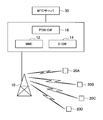
- FIG. 1 is an explanatory diagram showing a configuration example of the wireless communication system 1.
- the radio communication system 1 includes an eNodeB 10, a core management network including an MME (Mobility Management Entity) 12, an S-GW (Serving Gateway) 14, and a PDN (Packet Data Network) -GW 16, and an MTC.
- the terminal 20 and the MTC server 30 are provided.
- the embodiment of the present disclosure can be applied to wireless communication apparatuses such as the eNodeB 10 and the MTC terminal 20 illustrated in FIG.
- the eNodeB 10 and the MTC terminal 20 are only examples of wireless communication devices, and the embodiments of the present disclosure can be applied to various other wireless communication devices.
- Examples of other wireless communication devices include a user terminal (UE: User Equipment), a relay node that relays communication between the user terminal (MTC terminal 20) and the eNodeB 10, and a Home eNodeB that is a small home base station. .
- the eNodeB 10 is a radio base station that communicates with the MTC terminal 20. Although only one eNodeB 10 is shown in FIG. 1, a large number of eNodeBs are actually connected to the core network. Moreover, although description is abbreviate
- the MME 12 is a device that controls the setting, release, and handover of a data communication session.
- the MME 12 is connected to the eNodeB 10 via an interface called X2.
- the S-GW 14 is a device that performs routing and transfer of user data.
- the PDN-GW 16 functions as a connection point with the IP service network, and transfers user data to and from the IP service network.
- the MTC terminal 20 is a terminal specialized for an application for MTC being studied in 3GPP, and performs radio communication with the eNodeB 10 according to the application. Further, the MTC terminal 20 performs bidirectional communication with the MTC server 30 via the core network. The user executes a predetermined application by accessing the MTC server 30. The user basically does not access the MTC terminal 20 directly.
- the MTC terminal 20 will be described in detail in “1-4. MTC terminal”.
- FIG. 2 is an explanatory diagram showing a 4G frame format.
- a 10 ms radio frame is composed of ten 1 ms subframes # 0 to # 9.
- Each subframe of 1 ms is composed of two 0.5 ms slots.
- each 0.5 ms slot is composed of 7 Ofdm symbols.
- a synchronization signal used for frame synchronization by the user terminal is transmitted using the Ofdm symbol shaded in FIG. More specifically, the secondary synchronization signal is used for the fifth Ofdm symbol of subframe # 0, the primary synchronization signal is used for the sixth Ofdm symbol of subframe # 0, the secondary synchronization signal is used for the fifth Ofdm symbol of subframe # 5, and the fifth synchronization symbol of subframe # 5 is used. In 6Ofdm symbols, a primary synchronization signal is transmitted.
- the user terminal acquires a 5 ms period using the primary synchronization signal and simultaneously detects a cell number group corresponding to the current location from the three cell number groups. Thereafter, the user terminal acquires a radio frame period (10 ms period) using the secondary synchronization signal.
- a ZadoffChu sequence is used as the code sequence of the synchronization signal. Since 168 types of encoded sequences are used for the cell numbers in the cell number group and two types of encoded sequences are used to obtain a radio frame period, 336 types of encoded sequences are prepared. Based on the combination of the secondary synchronization signal transmitted in subframe # 0 and the secondary synchronization signal transmitted in subframe # 5, the user terminal determines whether the received subframe is subframe # 0 or subframe # 5 Can be judged.
- the user terminal After performing the frame synchronization as described above, the user terminal synchronizes the oscillator inside the user terminal with the oscillator of the eNodeB 10 with high accuracy. And a user terminal receives the signal transmitted from a base station periodically, and makes the oscillator of the base station of the oscillator inside a user terminal track. If there is a difference between the oscillator inside the user terminal and the oscillator of the base station, it becomes impossible to receive and transmit at an accurate frequency and time. Therefore, the accuracy of the oscillator inside the user terminal is important.
- Timing Advance The 4G user terminal performs time adjustment according to the distance between the eNodeB 10 and the user terminal, called Timing Advance, so that the radio signals transmitted from the plurality of user terminals are simultaneously received by the eNodeB 10. Specifically, Timing Advance is performed during a random access procedure in which a user terminal transmits a preamble toward a random access window. The Timing Advance value can be acquired from the relationship between the arrival time of the preamble to the eNodeB 10 and the random access window.
- the MTC terminal 20 performs the same Timing Advance as that of the user terminal and acquires the Timing Advance value.
- the MTC terminal 20 is a terminal specialized for an application for MTC which is being studied in 3GPP.
- An example of an application for MTC is shown below.
- the MTC terminal 20 may be an electrocardiogram measuring device corresponding to the above “4. Health”.
- the MTC server 30 requests the report of the electrocardiogram measurement result from the MTC terminal 20, and the measurement result of the electrocardiogram is received from the MTC terminal 20. Reported to the MTC server 30.
- the MTC terminal 20 may be a vending machine corresponding to the above “3. Payment”.
- the MTC server 30 requests the MTC terminal 20 to report the sales status, and the MTC terminal 20 reports the sales status to the MTC server 30.
- MTC terminal 20 The characteristics of such an MTC terminal 20 are shown below. Note that the MTC terminal 20 need not have all the following features.
- the MTC terminal 20 moves less, connects to the eNodeB 10 at a low frequency, performs a small amount of data communication, and returns to the idle mode again. In addition, a certain amount of delay is allowed for data communication. Further, the MTC terminal 20 is required to have ultra-low power consumption (13. Extra Low Power Consumption).
- the number of MTC terminals 20 existing in the future is predicted.
- about 2.7 billion people use cellular in the world population of over 6 billion.
- about 50 million machines use cellular as the MTC terminal 20.
- the MTC terminal 20 is not widespread at the present time, there is a possibility that the MTC terminal 20 of the order of 100 trillion will be accommodated by cellular in the world in the future. As a result, an enormous number of MTC terminals 20 are expected to be accommodated in each eNodeB 10.
- the MTC terminal 20 having characteristics such as Time Controlled and Online Small Data Transmissions.
- Such an MTC terminal 20 is expected to spend a lot of time in the idle mode, receive signals from the eNodeB 10 in a burst manner, or transmit a small amount of information to the eNodeB 10. Further, since the MTC terminal 20 is required to have low power consumption, it is desired to shorten the burst transmission / reception time as much as possible.
- this bursty transmission / reception is considered to be performed in a very long cycle of once per several hours or once every few days, not in the order of several ms or several tens of ms when the current LTE terminal receives the paging channel. It is done.
- FIG. 3 is an explanatory diagram showing resource blocks. As shown in FIG. 3, the resource blocks are arranged in a lattice shape in the frequency direction and the time direction. Each resource block is composed of 12 subcarriers ⁇ 7Ofdm symbols. Further, a guard interval is added to the head of each resource element composed of 1 subcarrier ⁇ 1Ofdm symbol.
- the eNodeB 10 can perform resource allocation in units of this resource block.
- FIG. 4 is an explanatory diagram showing a problem based on errors such as an oscillator inside the MTC terminal 20 and frame synchronization. For example, consider a case where resource blocks RB1 to RB3 are allocated for the uplink of MTC terminal 20A and resource block RB4 is allocated for the uplink of MTC terminal 20B. Furthermore, it is assumed that the oscillator inside the MTC terminal 20B has an error.
- the radio signal transmitted from the MTC terminal 20B to the eNodeB 10 in the resource block RB4 reaches the eNodeB 10 at a time and frequency that do not match the original resource block RB4, as shown in FIG.
- the radio signal transmitted from the MTC terminal 20B interferes with the radio signal transmitted from the MTC terminal 20A in the resource blocks RB1 to RB3 at the eNodeB 10.
- Such interference between resource blocks causes reception failure. Similar problems occur in the downlink.
- the embodiment of the present disclosure has been created with the above circumstances in mind. According to the embodiment of the present disclosure, it is possible to suppress the interference between resource blocks and the accompanying decrease in communication accuracy while reducing power consumption. Hereinafter, such an embodiment of the present disclosure will be described in detail.
- FIG. 5 is an explanatory diagram illustrating a configuration of the eNodeB 10 according to the embodiment of the present disclosure. As illustrated in FIG. 5, the eNodeB 10 includes a wireless communication unit 110, a control unit 120, and an upper layer 130.
- the wireless communication unit 110 has a function as a reception unit that receives control signals and data from the MTC terminal 20 and a transmission unit that transmits control signals and data to the MTC terminal 20.
- the wireless communication unit 210 performs wireless signal processing such as modulation / demodulation, signal mapping, demapping, and interleaving, and antenna signal processing. Normal data transmitted / received between the wireless communication unit 110 and the user terminal and MTC data transmitted / received between the wireless communication unit 110 and the MTC terminal 20 are input / output between the wireless communication unit 110 and the upper layer 130. .
- the wireless communication unit 110 also includes an MTC reference signal insertion unit 112, an MTC guard processing unit 114, and a channel estimation unit 116.
- the channel estimation unit 116 estimates the channel condition between the eNodeB 10 and the MTC terminal 20 based on the reference signal received from the MTC terminal 20.
- the MTC reference signal insertion unit 112 and the MTC guard processing unit 114 add the MTC reference signal and the MTC guard interval when the communication partner is the MTC terminal 20.
- the MTC reference signal and the MTC guard interval will be described in detail later.
- the control unit 120 is configured to control the overall communication of the eNodeB 10.
- the control unit 120 includes a scheduler 122 and a non-transmission area setting unit 124.
- the scheduler 122 allocates resource blocks to the MTC terminals 20 belonging to the eNodeB 10.
- the MTC terminal 20 performs uplink communication or downlink communication using the resource block allocated by the scheduler 122.
- the non-transmission area setting unit 124 sets the non-transmission area in the resource block allocated for downlink by the scheduler 122.
- the wireless communication unit 110 does not transmit a radio signal in the non-transmission area set by the non-transmission area setting unit 124, and transmits a radio signal only in other areas.
- the non-transmission area will be specifically described.
- Non-transmission area setting As described above with reference to FIG. 4, in both downlink communication and uplink communication, interference between resource blocks occurs due to errors such as an oscillator inside the MTC terminal 20 and frame synchronization. . Therefore, the non-transmission area setting unit 124 sets the non-transmission area at the boundary of at least one of the time direction and the frequency direction with the adjacent resource block in the resource block allocated for the downlink by the scheduler 122.
- FIG. 6 is an explanatory diagram showing an example of setting a non-transmission area.
- a non-transmission area is set at the boundary between each resource block and the adjacent resource block on the front side on the time axis and the boundary between the adjacent resource block on the lower side on the frequency axis.
- the resource block 3 includes one resource element at the boundary with the previous adjacent resource block RB1 on the time axis and the lower adjacent resource block RB4 on the frequency axis.
- the transmission area is set.
- the MTC terminal 20 receives only the radio signal transmitted from the eNodeB 10 in the resource block RB2. Can do.
- the resource elements set in the non-transmission area by the non-transmission area setting unit 124 are not limited to the example shown in FIG.
- the non-transmission area setting unit 124 may set a non-transmission area at the boundary between all resource blocks in the resource block.
- the non-transmission area setting unit 124 may set a plurality of resource elements at each boundary as a non-transmission area.
- the non-transmission area setting unit 124 may set different non-transmission areas for each resource block or for each MTC terminal 20 as a transmission destination.
- FIG. 7 is an explanatory diagram showing another setting example of the non-transmission area.
- the resource block RB1 shown in FIG. 7 includes two resource elements at the boundary with the adjacent resource block on the front side in the time direction, one resource element at the boundary with the adjacent resource block RB3 on the rear side, and the lower side in the frequency direction.
- a non-transmission area for one resource element is set at the boundary with the adjacent resource block RB2.
- the resource block RB2 has one resource element at the boundary with the previous adjacent resource block in the time direction, four resource elements at the boundary with the lower adjacent resource block RB in the frequency direction, and the upper adjacent in the frequency direction.
- a non-transmission area for three resource elements is set at the boundary with the resource block RB1.
- the non-transmission area setting unit 124 can set a different non-transmission area for each resource block or for each MTC terminal 20 as a transmission destination.
- it is effective to set the non-transmission area widely in the MTC terminal 20 having a large error such as an oscillator or frame synchronization. Therefore, the non-transmission area setting unit 124 may estimate the magnitude of the error of the MTC terminal 20 and set the non-transmission area according to the magnitude of the error. With this configuration, it is possible to prevent throughput from being lowered by setting a non-transmission area that is larger than necessary.
- the non-transmission area setting unit 124 may estimate the magnitude of the error of the MTC terminal 20 from, for example, the elapsed time from frame synchronization by the MTC terminal 20, the elapsed time from Timing Advance, the reception success rate, and the like. .
- the MTC reference signal insertion unit 112 inserts a reference signal into a resource block allocated for downlink to the MTC terminal 20.
- a reference signal Prior to a detailed description of the MTC reference signal insertion unit 112, an arrangement position of a normal reference signal having a user terminal as a transmission destination will be described with reference to FIG.
- FIG. 8 is an explanatory diagram showing a normal arrangement position of the reference signal.
- reference signals are inserted in a distributed manner into a plurality of resource elements in a resource block.
- the user terminal obtains channel information for receiving data by receiving this reference signal over one or more resource blocks and performing interpolation in the frequency direction and the time direction.
- a reference signal is similarly inserted in the uplink.
- each MTC terminal 20 uses a resource block having an error in the frequency direction and the time direction, so it is difficult for the eNodeB 10 to acquire channel information over a sufficient time based on the reference signal. is there.
- the MTC reference signal insertion unit 112 intensively inserts reference signals at the head of resource blocks allocated for downlink to the MTC terminal 20.
- a specific description will be given with reference to FIG.
- FIG. 9 is an explanatory diagram illustrating an arrangement example of reference signals according to an embodiment of the present disclosure.
- the MTC reference signal insertion unit 112 inserts a reference signal at the head of all frequencies used for transmission in each resource block.
- the MTC reference signal insertion unit 112 inserts a reference signal immediately after the non-transmission area, and the non-transmission area is not set. The reference signal is inserted at the head of the resource block.
- the MTC reference signal insertion unit 112 inserts the reference signal at all frequencies at all frequencies.
- the reference signal may be inserted at a part of the frequency instead of the entire frequency.
- the MTC guard processing unit 114 adds a guard interval to an Ofdm symbol whose destination is the MTC terminal 20 and cuts out data from the Ofdm symbol received from the MTC terminal 20.
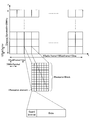
- a normal Ofdm symbol guard interval with the user terminal as the transmission destination will be described.
- the Ofdm symbol is composed of a guard interval and data, as shown in FIG.
- the normal guard interval is designed to be longer than the delay time of the reflected wave with the latest arrival time in order to suppress the influence of multipath. It is known that data can be correctly decoded if a signal of a predetermined length can be extracted from the Ofdm symbol comprising the guard interval and data.
- both the eNodeB 10 and the MTC terminal 20 accurately extract a signal from the received Ofdm symbol in a normal guard interval. It is difficult to do.
- the MTC guard processing unit 114 makes the guard interval longer than the normal length defined in LTE. For example, as shown in the lower part of FIG. 10, the MTC guard processing unit 114 makes the length of the guard interval longer than the data. With such a configuration, since the allowable amount of error related to the signal cut-out position in the MTC terminal 20 is greatly increased, it is possible to improve the reception success rate.
- the ratio between the guard interval length and the data length may be set to 80%: 20%.
- the MTC terminal 20 cuts out a signal from the center of the Ofdm symbol as shown in FIG. 11, so that the frame synchronization error of the MTC terminal 20 is ⁇ 40% to 40% of the Ofdm symbol length. If it is within the range, it is possible to correctly decode the data. In this way, in addition to setting the non-transmission area, by extending the guard interval, interference between resource blocks and interference between Ofdm symbols can be prevented.
- the MTC guard processing unit 114 may estimate the size of the error of the MTC terminal 20 and set the length of the guard interval according to the size of the error, similarly to the width of the non-transmission area. . With this configuration, it is possible to prevent throughput from being lowered by making the guard interval longer than necessary. Further, as in the modification shown in FIG. 12, the transmission areas of a plurality of Ofdm symbols may be used as one guard interval part and one data part. According to such a configuration, the guard interval can be further increased.
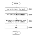
- FIG. 13 is a flowchart illustrating an operation of the eNodeB 10 according to the embodiment of the present disclosure.
- the scheduler 122 of the eNodeB 10 performs resource block scheduling for each MTC terminal 20 (S310).
- the non-transmission area setting unit 124 sets a non-transmission area in the resource block allocated for downlink by the scheduler 122 (S320).
- the non-transmission area setting unit 124 sets a non-transmission area at the boundary of at least one of the time direction and the frequency direction with the adjacent resource block in the resource block allocated for downlink by the scheduler 122.
- the MTC reference signal insertion unit 112 inserts a reference signal at the head of the resource block, and the MTC guard processing unit 114 adds a longer guard interval defined in LTE to each Ofdm symbol (S330). Thereafter, the wireless communication unit 110 transmits the signal obtained in S330 in an area other than the non-transmission area (S340).
- Configuration of MTC terminal> The configuration and operation of the eNodeB 10 according to the embodiment of the present disclosure have been described above. Next, the MTC terminal 20 according to the embodiment of the present disclosure will be described. Similar to the eNodeB 10, the MTC terminal 20 according to the embodiment of the present disclosure does not transmit in the non-transmission area, transmits the reference signal at the head of the resource block, and lengthens the guard interval, thereby interfering between resource blocks. And preventing interference between Ofdm. Hereinafter, the configuration of the MTC terminal 20 will be specifically described.
- FIG. 14 is an explanatory diagram showing a configuration of the MTC terminal 20 according to the embodiment of the present disclosure.
- the MTC terminal 20 according to the embodiment of the present disclosure includes a wireless communication unit 210, a control unit 220, and an upper layer 230.
- the wireless communication unit 210 has a function as a receiving unit that receives control signals and data from the eNodeB 10 and a transmitting unit that transmits control signals and data to the eNodeB 10. Specifically, the wireless communication unit 210 performs wireless signal processing such as modulation / demodulation, signal mapping, demapping, and interleaving, and antenna signal processing. MTC data transmitted and received between the radio communication unit 210 and the eNodeB 10 is input / output between the radio communication unit 210 and the upper layer 230.
- the wireless communication unit 210 includes an MTC reference signal insertion unit 212, an MTC guard processing unit 214, and a channel estimation unit 216.
- the channel estimation unit 216 estimates the channel condition between the eNodeB 10 and the MTC terminal 20 based on the reference signal received from the eNodeB 10.
- the MTC reference signal insertion unit 112 has substantially the same configuration as the MTC reference signal insertion unit 212 of the eNodeB 10. For example, the MTC reference signal insertion unit 112 inserts a reference signal at the beginning of all or some of the frequencies of the uplink resource block as shown in FIG. According to such a configuration, it is expected that the time required for the eNodeB 10 on the uplink receiving side to acquire the channel information is shortened.
- the MTC guard processing unit 214 has substantially the same configuration as the MTC guard processing unit 114 of the eNodeB 10. For example, the MTC guard processing unit 214 makes the length of the guard interval longer than the data as shown in FIG. With such a configuration, the tolerance for frame synchronization errors of the MTC terminal 20 is greatly increased, so that the reception success rate by the eNodeB 10 can be improved.
- the control unit 220 is configured to control the overall communication of the MTC terminal 20.
- the control unit 220 controls uplink communication and downlink communication by the MTC terminal 20 according to scheduling information received from the eNodeB 10, for example.
- control unit 220 causes the radio communication unit 210 to transmit a radio signal in an area other than the non-transmission area. Control. Note that the radio communication unit 210 performs reception processing on the entire allocated resource block in the downlink.
- control unit 220 may have substantially the same function as the non-transmission area setting unit 124 of the eNodeB 10. That is, the control unit 220 may set a non-transmission area in the uplink resource block allocated by the eNodeB 10.
- the control unit 220 may estimate the magnitude of an error such as the frequency or time of the MTC terminal 20 and set a non-transmission area according to the magnitude of the error. For example, the control unit 220 may set a wider non-transmission area as the error of the MTC terminal 20 is larger, and may set a smaller non-transmission area as the error of the MTC terminal 20 is smaller. With this configuration, it is possible to prevent throughput from being lowered by setting a non-transmission area that is larger than necessary.
- the control unit 120 may estimate the magnitude of the error of the MTC terminal 20 from, for example, the elapsed time from frame synchronization by the MTC terminal 20, the elapsed time from Timing Advance, the reception success rate, and the like.
- interference between resource blocks can be prevented by setting a non-transmission area even when there is an error in frame synchronization or frequency of the MTC terminal 20. .
- it is expected that the time required for the reception side apparatus to acquire the channel information is shortened by intensively inserting the reference signal at the head of the resource block.
Landscapes
- Engineering & Computer Science (AREA)
- Signal Processing (AREA)
- Computer Networks & Wireless Communication (AREA)
- Mobile Radio Communication Systems (AREA)
Abstract
Priority Applications (7)
| Application Number | Priority Date | Filing Date | Title |
|---|---|---|---|
| US13/641,633 US9301255B2 (en) | 2010-05-26 | 2011-05-17 | Wireless communication device and wireless communication method |
| EP11786519.6A EP2579656A4 (fr) | 2010-05-26 | 2011-05-17 | Dispositif de communication sans fil et procédé de communication sans fil |
| KR1020127029835A KR20130093503A (ko) | 2010-05-26 | 2011-05-17 | 무선 통신 장치 및 무선 통신 방법 |
| BR112012029460A BR112012029460A2 (pt) | 2010-05-26 | 2011-05-17 | "dispositivo e método de comunicação sem fio" |
| CN201180024314.XA CN102907149B (zh) | 2010-05-26 | 2011-05-17 | 无线通信装置和无线通信方法 |
| RU2012149195/07A RU2572096C2 (ru) | 2010-05-26 | 2011-05-17 | Устройство беспроводной связи и способ беспроводной связи |
| US15/055,309 US9629086B2 (en) | 2010-05-26 | 2016-02-26 | Wireless communication device and wireless communication method |
Applications Claiming Priority (2)
| Application Number | Priority Date | Filing Date | Title |
|---|---|---|---|
| JP2010-120633 | 2010-05-26 | ||
| JP2010120633A JP5589558B2 (ja) | 2010-05-26 | 2010-05-26 | 無線通信装置および無線通信方法 |
Related Child Applications (2)
| Application Number | Title | Priority Date | Filing Date |
|---|---|---|---|
| US13/641,633 A-371-Of-International US9301255B2 (en) | 2010-05-26 | 2011-05-17 | Wireless communication device and wireless communication method |
| US15/055,309 Continuation US9629086B2 (en) | 2010-05-26 | 2016-02-26 | Wireless communication device and wireless communication method |
Publications (1)
| Publication Number | Publication Date |
|---|---|
| WO2011148820A1 true WO2011148820A1 (fr) | 2011-12-01 |
Family
ID=45003811
Family Applications (1)
| Application Number | Title | Priority Date | Filing Date |
|---|---|---|---|
| PCT/JP2011/061254 WO2011148820A1 (fr) | 2010-05-26 | 2011-05-17 | Dispositif de communication sans fil et procédé de communication sans fil |
Country Status (8)
| Country | Link |
|---|---|
| US (2) | US9301255B2 (fr) |
| EP (1) | EP2579656A4 (fr) |
| JP (1) | JP5589558B2 (fr) |
| KR (1) | KR20130093503A (fr) |
| CN (2) | CN105101395A (fr) |
| BR (1) | BR112012029460A2 (fr) |
| RU (1) | RU2572096C2 (fr) |
| WO (1) | WO2011148820A1 (fr) |
Cited By (3)
| Publication number | Priority date | Publication date | Assignee | Title |
|---|---|---|---|---|
| CN104079337A (zh) * | 2013-03-27 | 2014-10-01 | 上海贝尔股份有限公司 | 一种机器类型通信的频率分集传输方法 |
| WO2017047325A1 (fr) * | 2015-09-17 | 2017-03-23 | 株式会社デンソー | Dispositif de communication |
| RU2787853C1 (ru) * | 2019-09-02 | 2023-01-13 | Хуавей Текнолоджиз Ко., Лтд. | Способ и устройство управления воздействием радиочастотного излучения беспроводного устройства и беспроводное устройство |
Families Citing this family (6)
| Publication number | Priority date | Publication date | Assignee | Title |
|---|---|---|---|---|
| GB2502274B (en) * | 2012-05-21 | 2017-04-19 | Sony Corp | Telecommunications systems and methods |
| US10932277B2 (en) | 2014-10-08 | 2021-02-23 | Telefonaktiebolaget Lm Ericsson (Publ) | Low latency transmission configuration |
| EP3205166B1 (fr) | 2014-10-08 | 2019-05-22 | Telefonaktiebolaget LM Ericsson (publ) | Configuration de canal d'accès aléatoire |
| CN107210881B (zh) | 2015-01-30 | 2021-01-29 | 瑞典爱立信有限公司 | 配置无线通信资源的方法、基站和通信装置 |
| US10045334B2 (en) * | 2015-02-13 | 2018-08-07 | Qualcomm Incorporated | Reference signal design for coverage enhancements |
| WO2018018377A1 (fr) * | 2016-07-25 | 2018-02-01 | 华为技术有限公司 | Procédé d'ordonnancement, procédé de régulation de puissance et station de base |
Citations (3)
| Publication number | Priority date | Publication date | Assignee | Title |
|---|---|---|---|---|
| JP2000013870A (ja) | 1998-06-25 | 2000-01-14 | Sony Corp | 通信方法、基地局及び端末装置 |
| JP2007300507A (ja) * | 2006-05-01 | 2007-11-15 | Ntt Docomo Inc | 送信装置及び受信装置 |
| WO2009120941A2 (fr) * | 2008-03-28 | 2009-10-01 | Qualcomm Incorporated | Transmission de messages de signalisation dans un réseau de communication sans fil |
Family Cites Families (8)
| Publication number | Priority date | Publication date | Assignee | Title |
|---|---|---|---|---|
| US7016319B2 (en) * | 2003-03-24 | 2006-03-21 | Motorola, Inc. | Method and apparatus for reducing co-channel interference in a communication system |
| JP4819911B2 (ja) * | 2006-01-20 | 2011-11-24 | ノキア コーポレイション | 強化サービス範囲を有するランダムアクセス手続 |
| JP4476968B2 (ja) | 2006-06-19 | 2010-06-09 | 株式会社エヌ・ティ・ティ・ドコモ | 移動通信システムにおける基地局、ユーザ装置、送信方法及び受信方法 |
| JP4412505B2 (ja) | 2007-08-08 | 2010-02-10 | 日本電気株式会社 | 無線通信システム |
| US8243678B2 (en) | 2008-03-10 | 2012-08-14 | Motorola Mobility, Inc. | Hierarchical pilot structure in wireless communication systems |
| US9276787B2 (en) | 2008-03-28 | 2016-03-01 | Qualcomm Incorporated | Transmission of signaling messages using beacon signals |
| WO2010140830A2 (fr) * | 2009-06-02 | 2010-12-09 | 엘지전자 주식회사 | Procédé d'atténuation de brouillage entre des cellules dans un système de communication sans fil et appareil associé |
| CN105812114B (zh) * | 2009-10-05 | 2019-08-06 | 瑞典爱立信有限公司 | 用于载波聚合的方法和装置 |
-
2010
- 2010-05-26 JP JP2010120633A patent/JP5589558B2/ja not_active Expired - Fee Related
-
2011
- 2011-05-17 CN CN201510421025.3A patent/CN105101395A/zh active Pending
- 2011-05-17 EP EP11786519.6A patent/EP2579656A4/fr not_active Withdrawn
- 2011-05-17 BR BR112012029460A patent/BR112012029460A2/pt not_active Application Discontinuation
- 2011-05-17 US US13/641,633 patent/US9301255B2/en active Active
- 2011-05-17 CN CN201180024314.XA patent/CN102907149B/zh not_active Expired - Fee Related
- 2011-05-17 WO PCT/JP2011/061254 patent/WO2011148820A1/fr active Application Filing
- 2011-05-17 KR KR1020127029835A patent/KR20130093503A/ko not_active Application Discontinuation
- 2011-05-17 RU RU2012149195/07A patent/RU2572096C2/ru not_active IP Right Cessation
-
2016
- 2016-02-26 US US15/055,309 patent/US9629086B2/en active Active
Patent Citations (3)
| Publication number | Priority date | Publication date | Assignee | Title |
|---|---|---|---|---|
| JP2000013870A (ja) | 1998-06-25 | 2000-01-14 | Sony Corp | 通信方法、基地局及び端末装置 |
| JP2007300507A (ja) * | 2006-05-01 | 2007-11-15 | Ntt Docomo Inc | 送信装置及び受信装置 |
| WO2009120941A2 (fr) * | 2008-03-28 | 2009-10-01 | Qualcomm Incorporated | Transmission de messages de signalisation dans un réseau de communication sans fil |
Non-Patent Citations (3)
| Title |
|---|
| "Study on facilitating machine to machine communication in 3GPP systems", 3GPP TR22.868 V8.0.0, March 2007 (2007-03-01), XP050361381 * |
| GSM: "Service requirements for machine-type communications;Stage1 (release 1)", 3GPP TS22.368 V1.1.1, November 2009 (2009-11-01), XP050400696 * |
| See also references of EP2579656A4 |
Cited By (4)
| Publication number | Priority date | Publication date | Assignee | Title |
|---|---|---|---|---|
| CN104079337A (zh) * | 2013-03-27 | 2014-10-01 | 上海贝尔股份有限公司 | 一种机器类型通信的频率分集传输方法 |
| WO2017047325A1 (fr) * | 2015-09-17 | 2017-03-23 | 株式会社デンソー | Dispositif de communication |
| JP2017060042A (ja) * | 2015-09-17 | 2017-03-23 | 株式会社デンソー | 通信装置 |
| RU2787853C1 (ru) * | 2019-09-02 | 2023-01-13 | Хуавей Текнолоджиз Ко., Лтд. | Способ и устройство управления воздействием радиочастотного излучения беспроводного устройства и беспроводное устройство |
Also Published As
| Publication number | Publication date |
|---|---|
| CN102907149B (zh) | 2015-09-23 |
| US20160205629A1 (en) | 2016-07-14 |
| EP2579656A4 (fr) | 2015-10-07 |
| CN105101395A (zh) | 2015-11-25 |
| BR112012029460A2 (pt) | 2017-03-01 |
| JP2011250091A (ja) | 2011-12-08 |
| US20130034079A1 (en) | 2013-02-07 |
| EP2579656A1 (fr) | 2013-04-10 |
| RU2572096C2 (ru) | 2015-12-27 |
| JP5589558B2 (ja) | 2014-09-17 |
| RU2012149195A (ru) | 2014-05-27 |
| US9629086B2 (en) | 2017-04-18 |
| KR20130093503A (ko) | 2013-08-22 |
| US9301255B2 (en) | 2016-03-29 |
| CN102907149A (zh) | 2013-01-30 |
Similar Documents
| Publication | Publication Date | Title |
|---|---|---|
| US11006427B2 (en) | Communication system, base station, and communication terminal for controlling interference from neighboring cells | |
| US9629086B2 (en) | Wireless communication device and wireless communication method | |
| EP3427408B1 (fr) | Relais pour communication de type machine améliorée et internet des objets à bande étroite | |
| TWI700913B (zh) | 使用者設備及其無線通訊方法 | |
| TWI734972B (zh) | 使用者設備之無線通訊方法及裝置、電腦可讀介質 | |
| CN110073712B (zh) | 经由经协调的空闲信道评估和切换信令的频带选择 | |
| TW202038659A (zh) | 同步上行鏈路傳輸方法、裝置及電腦可讀介質 | |
| CN111771418A (zh) | 用于由用户设备进行的波束故障恢复请求的系统和方法 | |
| JP5732753B2 (ja) | 無線通信装置、無線通信システムおよび無線通信方法 | |
| CN112470540A (zh) | 用于窄带通信中上行链路传输的资源和方案 | |
| CN112913307B (zh) | 减少辅小区激活延迟的技术 | |
| CN115606109A (zh) | 网络辅助侧行链路波束故障恢复 | |
| US11812470B2 (en) | Receiver feedback about potential collisions | |
| WO2015026281A1 (fr) | Coordination destinée à un pbch | |
| JP2022511095A (ja) | Cot中で選択されるcoresetのサブセットのシグナリング | |
| CN112806033A (zh) | 基于v2x网络的中继 | |
| US20140064103A1 (en) | Apparatus and Method For Declaring Radio Link Failure (RLF) | |
| CN114223147A (zh) | 用于侧链路传输的拥塞控制 | |
| CN106664728B (zh) | 随机接入信道传输方法和装置 | |
| JP2024514131A (ja) | 処理能力が制約されたシナリオにおいてマルチrtt測位を改善するためにprsとsrsとの関連付けを定義すること |
Legal Events
| Date | Code | Title | Description |
|---|---|---|---|
| WWE | Wipo information: entry into national phase |
Ref document number: 201180024314.X Country of ref document: CN |
|
| 121 | Ep: the epo has been informed by wipo that ep was designated in this application |
Ref document number: 11786519 Country of ref document: EP Kind code of ref document: A1 |
|
| WWE | Wipo information: entry into national phase |
Ref document number: 13641633 Country of ref document: US |
|
| ENP | Entry into the national phase |
Ref document number: 20127029835 Country of ref document: KR Kind code of ref document: A |
|
| ENP | Entry into the national phase |
Ref document number: 2012149195 Country of ref document: RU Kind code of ref document: A |
|
| WWE | Wipo information: entry into national phase |
Ref document number: 9724/CHENP/2012 Country of ref document: IN Ref document number: 2011786519 Country of ref document: EP |
|
| NENP | Non-entry into the national phase |
Ref country code: DE |
|
| REG | Reference to national code |
Ref country code: BR Ref legal event code: B01A Ref document number: 112012029460 Country of ref document: BR |
|
| ENP | Entry into the national phase |
Ref document number: 112012029460 Country of ref document: BR Kind code of ref document: A2 Effective date: 20121119 |