WO2011148656A1 - 表示装置 - Google Patents
表示装置 Download PDFInfo
- Publication number
- WO2011148656A1 WO2011148656A1 PCT/JP2011/050235 JP2011050235W WO2011148656A1 WO 2011148656 A1 WO2011148656 A1 WO 2011148656A1 JP 2011050235 W JP2011050235 W JP 2011050235W WO 2011148656 A1 WO2011148656 A1 WO 2011148656A1
- Authority
- WO
- WIPO (PCT)
- Prior art keywords
- display panel
- holding member
- display device
- holding
- liquid crystal
- Prior art date
- Legal status (The legal status is an assumption and is not a legal conclusion. Google has not performed a legal analysis and makes no representation as to the accuracy of the status listed.)
- Ceased
Links
Images











Classifications
-
- G—PHYSICS
- G02—OPTICS
- G02F—OPTICAL DEVICES OR ARRANGEMENTS FOR THE CONTROL OF LIGHT BY MODIFICATION OF THE OPTICAL PROPERTIES OF THE MEDIA OF THE ELEMENTS INVOLVED THEREIN; NON-LINEAR OPTICS; FREQUENCY-CHANGING OF LIGHT; OPTICAL LOGIC ELEMENTS; OPTICAL ANALOGUE/DIGITAL CONVERTERS
- G02F1/00—Devices or arrangements for the control of the intensity, colour, phase, polarisation or direction of light arriving from an independent light source, e.g. switching, gating or modulating; Non-linear optics
- G02F1/01—Devices or arrangements for the control of the intensity, colour, phase, polarisation or direction of light arriving from an independent light source, e.g. switching, gating or modulating; Non-linear optics for the control of the intensity, phase, polarisation or colour
- G02F1/13—Devices or arrangements for the control of the intensity, colour, phase, polarisation or direction of light arriving from an independent light source, e.g. switching, gating or modulating; Non-linear optics for the control of the intensity, phase, polarisation or colour based on liquid crystals, e.g. single liquid crystal display cells
- G02F1/133—Constructional arrangements; Operation of liquid crystal cells; Circuit arrangements
- G02F1/1333—Constructional arrangements; Manufacturing methods
- G02F1/133308—Support structures for LCD panels, e.g. frames or bezels
-
- G—PHYSICS
- G02—OPTICS
- G02F—OPTICAL DEVICES OR ARRANGEMENTS FOR THE CONTROL OF LIGHT BY MODIFICATION OF THE OPTICAL PROPERTIES OF THE MEDIA OF THE ELEMENTS INVOLVED THEREIN; NON-LINEAR OPTICS; FREQUENCY-CHANGING OF LIGHT; OPTICAL LOGIC ELEMENTS; OPTICAL ANALOGUE/DIGITAL CONVERTERS
- G02F1/00—Devices or arrangements for the control of the intensity, colour, phase, polarisation or direction of light arriving from an independent light source, e.g. switching, gating or modulating; Non-linear optics
- G02F1/01—Devices or arrangements for the control of the intensity, colour, phase, polarisation or direction of light arriving from an independent light source, e.g. switching, gating or modulating; Non-linear optics for the control of the intensity, phase, polarisation or colour
- G02F1/13—Devices or arrangements for the control of the intensity, colour, phase, polarisation or direction of light arriving from an independent light source, e.g. switching, gating or modulating; Non-linear optics for the control of the intensity, phase, polarisation or colour based on liquid crystals, e.g. single liquid crystal display cells
- G02F1/133—Constructional arrangements; Operation of liquid crystal cells; Circuit arrangements
- G02F1/1333—Constructional arrangements; Manufacturing methods
- G02F1/133308—Support structures for LCD panels, e.g. frames or bezels
- G02F1/133322—Mechanical guidance or alignment of LCD panel support components
Definitions
- the present invention relates to a display device, and more particularly to a display device including a holding member that holds an edge of a display panel.
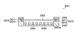
- FIG. 21 is a cross-sectional view illustrating a structure of a display device according to a conventional example including a holding member that holds an edge of a display panel.
- FIG. 22 is an enlarged cross-sectional view showing the structure of the display device according to the conventional example shown in FIG.
- a display device 2001 includes a display panel 2002, a holding member 2010 that holds an edge of the display panel 2002, a backlight chassis 2003 and a bezel 2004 that hold the holding member 2010, And a plurality of light sources 2005 housed in the recesses 2003a of the backlight chassis 2003.
- the holding member 2010 includes a pressing member (front side holding portion) 2011 that presses the front surface of the display panel 2002, and a supporting member (back side holding portion) 2012 that contacts the back surface of the display panel 2002. Including.
- the display panel 2002 is held by the pressing member 2011 and the support member 2012.
- Patent Document 1 a display device including a holding member that holds an edge of a display panel, such as a display device 2001 according to a conventional example, is disclosed in, for example, Patent Document 1.
- the display device 2001 according to the conventional example has a problem that the display panel 2002 may move (position shift or drop) in the surface direction due to vibration or the like.
- a display device capable of solving the above-described problems is required.
- the present invention has been made to solve the above-described problems, and an object of the present invention is to provide a display device capable of suppressing the movement of the display panel in the surface direction. .
- a display device includes a display panel and a holding member that holds an edge of the display panel, and the holding member is disposed on the front side of the display panel.
- the holding member is disposed on the front side of the display panel.
- the front side holding part, the back side holding part and the restricting part are integrally formed.
- the holding member is provided on the side of the display panel and provided with a restriction unit that restricts the display panel from moving in the surface direction of the display panel. Even if the friction coefficients of the front-side holding part and the back-side holding part are small, the restricting part can restrict the display panel from moving in the surface direction. That is, the display panel can be prevented from being displaced or dropped in the surface direction.
- the front side holding portion, the back side holding portion, and the regulating portion are integrally formed, thereby suppressing an increase in the number of parts of the holding member. And the assembly process of the display device can be simplified.
- the front side holding part, the back side holding part and the regulating part integrally forming the front side holding part, the back side holding part and the regulating part, for example, if at least one of the front side holding part and the back side holding part is fixed to a bezel, a backlight chassis or the like, Even if the restricting portion is not fixed to the bezel, the backlight chassis, or the like, the restricting portion can be prevented from moving in the surface direction of the display panel.
- the display device preferably further includes a fixing member for fixing the holding member, and the holding member has a first engagement portion, and the fixing member has the first engagement.
- the second engaging portion is formed to prevent the holding member from moving in the surface direction. If comprised in this way, since it can suppress that a holding member moves to the surface direction of a display panel, it can suppress easily that a display panel moves to a surface direction by a holding member (regulation part). Can do.
- the first engaging portion may be formed on at least one of the front side holding portion and the back side holding portion of the holding member.
- the restricting portion is preferably formed of the same member as at least one of the front side holding portion and the back side holding portion. If comprised in this way, since it is not necessary to provide an adhesive layer etc. between one side of a control part and a front side holding
- the front-side holding portion, the restricting portion, and the back-side holding portion are made of the same member. Is formed. If comprised in this way, a holding member can be manufactured more easily. Further, the strength of the holding member can be improved as compared with the case where the front side holding portion, the regulating portion, and the back side holding portion are integrally formed using an adhesive layer or the like.
- the holding member may be formed of urethane foam.
- the holding member is preferably formed of a heat dissipation sheet. If comprised in this way, since the heat
- the heat radiating sheet preferably contains a metal powder. If comprised in this way, since the function which shields electromagnetic waves can be provided to a holding member (heat dissipation sheet), the electromagnetic waves generated by a display panel can be shielded by the holding members. Thereby, electromagnetic waves generated in the display panel can be prevented from leaking to the outside, and EMI (Electro Magnetic Interference) can be reduced. Further, since the electromagnetic wave generated in the display panel can be shielded at a position close to the generation source (display panel), the electromagnetic wave can be effectively shielded.
- EMI Electro Magnetic Interference
- a heat conductive sheet is provided on the outer surface of the holding member. If comprised in this way, since the heat
- the display device preferably further includes a chassis that contacts the holding member, and at least a part of the portion that contacts the holding member of the chassis is formed of metal. If comprised in this way, since the heat
- the holding member preferably includes a first sponge member and a second sponge member having a higher elastic modulus than the first sponge member, and the front side holding portion and the back side holding portion. At least one of these is formed of a first sponge member, and the restricting portion is formed of a second sponge member. If comprised in this way, while a display panel is hold
- an adhesive layer for bonding the holding member and the display panel is preferably provided between the holding member and the display panel. If comprised in this way, it can suppress more that a display panel moves with respect to a holding member.
- the holding member preferably has a function of shielding electromagnetic waves. If comprised in this way, since the electromagnetic wave generate
- the holding member has a function of shielding electromagnetic waves
- the holding member includes a conductive cloth. If comprised in this way, electromagnetic waves can be easily shielded with a conductive cloth.
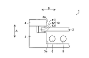
- FIG. 1 is a cross-sectional view illustrating a structure of a liquid crystal display device according to a first embodiment of the present invention.
- FIG. 2 is an enlarged cross-sectional view illustrating the structure of the liquid crystal display device according to the first embodiment of the present invention illustrated in FIG. 1.
- FIG. 2 is an enlarged view showing a structure of a holding member of the liquid crystal display device according to the first embodiment of the present invention shown in FIG. 1. It is the expanded sectional view which showed the structure of the liquid crystal display device by 2nd Embodiment of this invention.
- FIG. 5 is an enlarged view showing a structure of a holding member of the liquid crystal display device according to the second embodiment of the present invention shown in FIG. 4.
- FIG. 5 is an enlarged view showing a structure of a holding member of the liquid crystal display device according to the second embodiment of the present invention shown in FIG. 4.
- FIG. 5 is an enlarged view showing structures of a bezel and a backlight chassis of a liquid crystal display device according to a second embodiment of the present invention shown in FIG. 4. It is the enlarged view which showed the structure of the holding member of 3rd Embodiment of this invention. It is the enlarged view which showed the structure of the holding member of 4th Embodiment of this invention. It is the enlarged view which showed the structure of the holding member of 5th Embodiment of this invention. It is the expanded sectional view which showed the structure of the holding member of 5th Embodiment of this invention shown in FIG. It is an enlarged view for demonstrating the structure of the holding member of 5th Embodiment of this invention shown in FIG.
- hatching may be performed even in a cross-sectional view, or hatching may be performed even in a cross-sectional view.
- the liquid crystal display device 1 constitutes, for example, a liquid crystal television receiver (not shown).
- the liquid crystal display device 1 includes a liquid crystal display panel 2, a holding member 10 that holds an edge of the liquid crystal display panel 2, a backlight chassis 3 and a bezel 4 that hold the holding member 10. And a plurality of light sources 5 housed in the recesses 3 a of the backlight chassis 3.
- the backlight chassis 3 and the plurality of light sources 5 constitute a direct type backlight device.
- the liquid crystal display device 1 is an example of the “display device” in the present invention
- the liquid crystal display panel 2 is an example of the “display panel” in the present invention.
- the liquid crystal display panel 2 includes two glass substrates that sandwich a liquid crystal layer (not shown).
- the liquid crystal display panel 2 is provided with a plurality of wirings (not shown).
- the liquid crystal display panel 2 functions as a display panel when illuminated by the light source 5.
- the holding member 10 is provided on four edges (four sides) of the liquid crystal display panel 2.
- the holding member 10 is formed in an elongated shape along the edge of the liquid crystal display panel 2.
- the holding member 10 is formed in a U shape when viewed in cross section as shown in FIGS.
- the holding member 10 includes a front-side holding unit 11 disposed on the front (upper surface) side of the edge of the liquid crystal display panel 2 (see FIG. 2) and a regulation unit 12 disposed on the side of the liquid crystal display panel 2. And a back side holding portion 13 disposed on the back side (lower surface) side of the edge of the liquid crystal display panel 2.
- the front side holding part 11, the regulating part 12, and the back side holding part 13 are integrally formed.
- the front side holding part 11, the regulating part 12, and the back side holding part 13 are formed by one member (the same member) without using an adhesive layer or the like.
- the holding member 10 is made of, for example, urethane foam. If the holding member 10 is made of, for example, PORON (registered trademark), the friction coefficient of the holding member 10 can be made relatively large.
- an adhesive layer (not shown) is provided on the front surface (upper surface) and back surface (lower surface) of the holding member 10 (the front side holding portion 11 and the back side holding portion 13), and the holding member 10 is attached to the bezel 4 by the adhesive layer. Further, it may be bonded to the backlight chassis 3.
- the holding member 10 is integrally formed with the front side holding part 11, the regulating part 12, and the back side holding part 13, an adhesive layer is provided only on one of the front side and the back side of the holding member 10, and the bonding is performed. The holding member 10 may be adhered to only one of the bezel 4 and the backlight chassis 3 by the layer.
- the holding member 10 (the front side holding part 11 and the back side holding part 13) holds the liquid crystal display panel 2 by being sandwiched between the bezel 4 and the backlight chassis 3. And the movement of the liquid crystal display panel 2 in the thickness direction (A direction) is regulated (suppressed) by the front side holding part 11 and the back side holding part 13. Further, movement of the liquid crystal display panel 2 in the surface direction (the B direction orthogonal to the A direction) is restricted by the restricting unit 12.
- the backlight chassis 3 is made of resin, for example.
- the backlight chassis 3 is formed with recesses 3 a for storing a plurality of light sources 5.
- an optical sheet such as a prism sheet or a lens sheet may be disposed between the light source 5 and the liquid crystal display panel 2.
- a sheet (not shown) may be disposed.
- the light source 5 is formed of, for example, a fluorescent lamp.
- the light source 5 may be formed of, for example, an LED (Light Emitting Diode) other than the fluorescent lamp.
- the bezel 4 is made of sheet metal (metal), for example. Further, the bezel 4 is provided with an opening 4 a in a portion corresponding to the display area of the liquid crystal display panel 2.
- the holding member 10 is provided with the restricting portion 12 that is disposed on the side of the liquid crystal display panel 2 and restricts the liquid crystal display panel 2 from moving in the surface direction (B direction).
- the restriction part 12 restricts the liquid crystal display panel 2 from moving in the surface direction. Can do. That is, the liquid crystal display panel 2 can be prevented from being displaced or dropped in the surface direction.
- the front-side holding part 11, the restriction part 12, and the back-side holding part 13 are integrally formed to suppress an increase in the number of parts of the holding member 10. As a result, the assembly process of the liquid crystal display device 1 can be simplified.
- one of the front side holding part 11 and the back side holding part 13 is connected to the bezel 4 or the backlight chassis 3. If the restriction part 12 is not fixed to the bezel 4 or the backlight chassis 3, the restriction part 12 can be prevented from moving in the surface direction of the liquid crystal display panel 2.
- the front-side holding unit 11, the regulating unit 12, and the back-side holding unit 13 are formed of one (same) member, thereby restricting the front-side holding unit 11 and the regulating unit. Since it is not necessary to provide an adhesive layer between the portion 12 and between the regulating portion 12 and the back side holding portion 13, the holding member 10 can be easily manufactured. In addition, the strength of the holding member 10 can be improved as compared to the case where the front side holding portion 11, the regulating portion 12, and the back side holding portion 13 are integrally formed using an adhesive layer or the like.
- the friction coefficient of the holding member 10 can be made relatively large. Can be further suppressed.
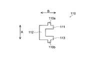
- the holding member 110 includes a front side holding portion 111 disposed on the front side of the liquid crystal display panel 2 (see FIG. 4) and the liquid crystal display panel 2 side. It is comprised by the control part 112 arrange
- the front side holding portion 111 is formed with a protrusion 110a that protrudes toward the bezel 104 (see FIG. 4).
- the bezel 104 is an example of the “fixing member” in the present invention
- the protrusion 110a is an example of the “first engaging portion” in the present invention.
- the rear side holding portion 113 is formed with a protrusion 110b that protrudes toward the backlight chassis 103 (see FIG. 4).
- the backlight chassis 103 is an example of the “fixing member” in the present invention
- the protrusion 110b is an example of the “first engaging portion” in the present invention.
- the bezel 104 is formed with a concave engaging portion (concave portion) 104 a that engages with the protruding portion 110 a of the holding member 110 (see FIG. 4).
- the engaging portion 104a is an example of the “second engaging portion” in the present invention.
- the backlight chassis 103 is formed with a concave engaging portion (concave portion) 103a that engages with the protruding portion 110b of the holding member 110 (see FIG. 4).
- the engaging portion 103a is an example of the “second engaging portion” in the present invention.
- the protrusion 110a is formed on the front side holding part 111, and the engaging part 104a with which the protrusion 110a is engaged is formed on the bezel 104, whereby the holding member 110 is formed. Can be prevented from moving in the surface direction (B direction) of the liquid crystal display panel 2. Accordingly, the holding member 110 can easily restrict the liquid crystal display panel 2 from moving in the surface direction (B direction).
- the protrusion 110b is formed on the back side holding portion 113, and the engaging portion 103a with which the protrusion 110b is engaged is formed on the backlight chassis 103, so that the holding member 110 of the liquid crystal display panel 2 is formed. It can suppress more moving to a surface direction (B direction).
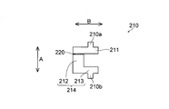
- an adhesive layer 220 is provided between the front surface side holding portion 211 and the regulating portion 212 of the holding member 210. The case will be described.
- the holding member 210 includes a front side holding part 211 disposed on the front side of the liquid crystal display panel 2 and a regulation part 212 disposed on the side of the liquid crystal display panel 2. And a back side holding part 213 disposed on the back side of the liquid crystal display panel 2.
- the restricting portion 212 and the back side holding portion 213 are formed by one (same) member 214 without using an adhesive layer or the like.
- an adhesive layer 220 is provided between the front-side holding part 211 and the restricting part 212, and the front-side holding part 211 and the restricting part 212 (member 214) are fixed by the adhesive layer 220. ing.
- the front side holding part 211, the regulation part 212, and the back side holding part 213 are integrally formed.
- the front side holding portion 211 is formed with a protruding portion 210a that protrudes toward the bezel 104
- the rear side holding portion 213 is formed with a protruding portion 210b that protrudes toward the backlight chassis 103 side.
- the protrusions 210a and 210b are examples of the “first engagement portion” in the present invention.
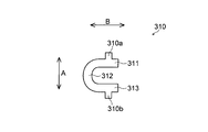
- the holding member 310 is formed in a substantially U shape when viewed in cross section.
- the holding member 310 is disposed on the front side of the liquid crystal display panel 2, the front side holding unit 311, the regulation unit 312 disposed on the side of the liquid crystal display panel 2, and the rear side of the liquid crystal display panel 2.
- the back side holding part 313 is comprised.
- front side holding part 311, the regulation part 312 and the back side holding part 313 are formed of one member (the same member) without using an adhesive layer or the like.
- the front side holding portion 311 is formed with a protruding portion 310a that protrudes toward the bezel 104
- the rear side holding portion 313 is formed with a protruding portion 310b that protrudes toward the backlight chassis 103.
- the protrusions 310a and 310b are examples of the “first engagement portion” in the present invention.
- the holding member 310 is formed of a rubber sheet having a relatively low elastic modulus such as urethane rubber or silicone rubber.
- the holding member 310 may be formed of urethane foam such as Polon (registered trademark), for example.
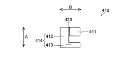
- the front side holding portion 411 and the regulating portion 412 of the holding member 410 have different elastic moduli. The case where it is formed in this way will be described.
- the holding member 410 includes a front side holding part 411 arranged on the front side of the liquid crystal display panel 2 and a regulation part 412 arranged on the side of the liquid crystal display panel 2. And a back side holding portion 413.
- the regulating portion 412 and the back side holding portion 413 are formed by one (same) member 414 without using an adhesive layer or the like.
- an adhesive layer 420 is provided between the front side holding portion 411 and the restricting portion 412 (member 414), and the front side holding portion 411 and the restricting portion 412 (member 414) are provided by the adhesive layer 420. And are fixed. In this way, the front side holding part 411, the regulating part 412 and the back side holding part 413 are integrally formed.
- the adhesive layer 420 is provided on a part of the boundary surface between the front side holding part 411 and the restricting part 412 (member 414). Note that the adhesive layer 420 may be provided on the entire boundary surface between the front surface side holding portion 411 and the restricting portion 412 (member 414).
- the front surface side holding portion 411 and the member 414 are formed by sponge members 411a and 414a, respectively.
- the sponge members 411a and 414a are formed of a foam such as urethane foam, for example.
- the sponge member 411a is an example of the “first sponge member” in the present invention
- the sponge member 414a is an example of the “second sponge member” in the present invention.
- the sponge member 414a of the restricting portion 412 (member 414) has a higher elastic modulus than the sponge member 411a of the front surface side holding portion 411.
- the sponge member 411a of the front side holding portion 411 has a lower elastic modulus than the sponge member 414a of the regulating portion 412 (member 414).
- the sponge member 414a (see FIG. 10) of the restricting portion 412 has a higher elastic modulus than the sponge member 411a (see FIG. 10) of the front side holding portion 411. It is possible to prevent the restricting portion 412 from being compressed when moving in the surface direction (B direction). That is, it is possible to restrict the liquid crystal display panel 2 from moving in the surface direction (B direction).
- the restricting portion 412 in order to form the sponge member 414a of the restricting portion 412 (member 414) to have a higher elastic modulus than the sponge member 411a of the front side holding portion 411, the restricting portion 412 (member 414) is formed.
- the sponge member 414a is formed with a lower foaming rate than the sponge member 411a of the front side holding portion 411.
- an adhesive layer (not shown) may be provided on the front surface (upper surface) and back surface (lower surface) of the holding member 410, and the holding member 410 may be bonded to the bezel 4 or the backlight chassis 3 by the adhesive layer. Note that when the sponge member 414a of the member 414 has a sufficiently high elastic modulus, a protrusion may be formed on the member 414.
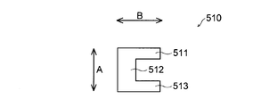
- the holding member 510 is formed of, for example, a gasket.
- the holding member 510 is formed by a U-shaped sponge member 510a used as a core material and a conductive cloth 510b that wraps the sponge member 510a.
- maintenance part 511 (refer FIG. 13), the control part 512, and the back side holding
- the sponge member 510a is formed of, for example, a foam such as urethane foam.
- the conductive cloth 510b is formed of, for example, conductive fibers obtained by performing metal plating on a polyester woven cloth, and has a function of shielding electromagnetic waves. For this reason, the front surface side holding portion 511 (see FIG. 13), the regulating portion 512, and the back surface side holding portion 513 of the holding member 510 have a function of shielding electromagnetic waves.
- an adhesive layer (not shown) may be provided on the front side or the back side of the conductive cloth 510b, and the holding member 510 may be bonded to the bezel 4 or the backlight chassis 3 by the adhesive layer.
- the other structure of the sixth embodiment is the same as that of the first to fifth embodiments.
- the holding member 510 is formed so as to have a function of shielding electromagnetic waves, so that the electromagnetic waves generated in the liquid crystal display panel 2 can be shielded by the holding member 510.
- the electromagnetic waves generated in the liquid crystal display panel 2 can be prevented from leaking to the outside, and EMI can be reduced. Further, since the electromagnetic wave generated in the liquid crystal display panel 2 can be shielded at a position close to the generation source (liquid crystal display panel 2), the electromagnetic wave can be effectively shielded.
- the holding member 510 is formed using the conductive cloth 510b, so that the electromagnetic cloth can be easily shielded by the conductive cloth 510b.
- the holding member 610 includes a rubber sheet 611 and a conductive cloth 612 disposed on the outer surface of the rubber sheet 611. And the front side holding
- the rubber sheet 611 is formed of a member having a relatively low elastic modulus, such as urethane rubber or silicone rubber.
- the rubber sheet 611 has a thickness of about 1 mm to about 2 mm, for example.
- the rubber sheet 611 is formed in a substantially U shape when viewed in cross section, and a portion 611 a disposed on the front side of the liquid crystal display panel 2 and a portion 611 b disposed on the side of the liquid crystal display panel 2. And a portion 611 c disposed on the back side of the liquid crystal display panel 2.
- the conductive cloth 612 is formed in a substantially U shape when viewed in cross section, and is disposed on the front side of the liquid crystal display panel 2 and on the side of the liquid crystal display panel 2. And a portion 612c arranged on the back side of the liquid crystal display panel 2.
- the front side holding portion 610a that presses the front surface of the edge of the liquid crystal display panel 2 is configured by the portion 611a of the rubber sheet 611 and the portion 612a of the conductive cloth 612.
- the portion 611b of the rubber sheet 611 and the portion 612b of the conductive cloth 612 constitute a restricting portion 610b that restricts the liquid crystal display panel 2 from moving in the surface direction (B direction).
- the portion 611 c of the rubber sheet 611 and the portion 612 c of the conductive cloth 612 constitute a back side holding portion 610 c that comes into contact with the back surface of the liquid crystal display panel 2.
- an adhesive layer (not shown) may be provided between the rubber sheet 611 and the conductive cloth 612, and the conductive cloth 612 may be bonded to the rubber sheet 611 by the adhesive layer.
- a convex portion 611d that protrudes toward the bezel is formed on the portion 611a of the rubber sheet 611.
- the convex part 612d is also formed in the part 612a of the conductive cloth 612 that covers the part 611a of the rubber sheet 611.
- a protrusion 610 d is formed by the protrusion 611 d of the rubber sheet 611 and the protrusion 612 d of the conductive cloth 612.
- the protrusion 610d is an example of the “first engagement portion” in the present invention.
- a convex portion 611e protruding toward the backlight chassis is formed on the portion 611c of the rubber sheet 611.
- the convex part 612e is formed also in the part 612c of the electrically conductive cloth 612 which covers the part 611c of the rubber sheet 611.
- a protrusion 610 e is formed by the protrusion 611 e of the rubber sheet 611 and the protrusion 612 e of the conductive cloth 612.
- the protrusion 610e is an example of the “first engagement portion” in the present invention.
- the effect of the seventh embodiment is the same as that of the first to sixth embodiments.
- the display panel and the display device are applied to a liquid crystal display panel and a liquid crystal display device.
- the present invention is not limited thereto, and may be applied to a display device other than a liquid crystal display device. Good.
- the present invention can be applied to both a small display device and a large display device.
- the present invention is applied to a large display device. It is particularly effective to apply to.
- the liquid crystal display device is formed by a direct-type backlight device.
- the present invention is not limited thereto, and the liquid crystal display device is formed by a sidelight-type backlight device. May be.
- a light guide plate (light guide member) that guides light from the light source may be provided.
- this invention is not limited to this, For example, you may form a sponge member with rubber
- the present invention is not limited thereto, and the front side of the holding member is shown.
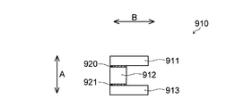
- the front side holding part 911, the regulating part 912, and the back side holding part 913 may be constituted by three or more members.
- the adhesive layer 920 may be disposed between the front side holding part 911 and the restricting part 912, and the front side holding part 911 and the restricting part 912 may be adhered by the adhesive layer 920.
- an adhesive layer 921 may be disposed between the restricting portion 912 and the back side holding portion 913, and the restricting portion 912 and the back side holding portion 913 may be bonded by the adhesive layer 921.
- the sponge member of the restricting portion in order to form the sponge member of the restricting portion so as to have a higher elastic modulus than the sponge member of the front holding portion, the sponge member of the restricting portion is replaced with the sponge of the front holding portion.
- the foaming rate is smaller than that of the member
- the present invention is not limited to this, and the restriction member sponge member and the front surface holding member sponge member are formed by using different materials.
- the sponge member may be formed to have a higher elastic modulus than the sponge member of the front side holding portion.
- the holding member may be formed of a heat dissipation sheet.
- the heat of the liquid crystal display panel (the heat generated in the liquid crystal display panel or the heat generated by the light source and transmitted to the liquid crystal display panel) is transferred to the outside (bezel or backlight chassis) via the holding member. Can dissipate heat. Thereby, it can suppress that a liquid crystal display panel (liquid crystal display device) becomes high temperature.
- the heat-dissipating sheet used for the holding member preferably has an Asker C hardness of, for example, about 40 degrees to about 60 degrees.
- the heat dissipation sheet (holding member) may contain metal powder such as ferrite, for example. If comprised in this way, since the function which shields electromagnetic waves can be provided to a heat radiating sheet (holding member), the electromagnetic waves which generate
- the present invention is not limited to this, and heat conduction with good heat conductivity is provided on the outer surface of the holding member.
- a sheet may be provided.
- the liquid crystal display device according to the fourth modification of the present invention shown in FIG. 18 may be configured. That is, as shown in FIG. 18, the backlight chassis 1003 may be formed so as to sandwich the holding member 1010 from both sides in the A direction, and the bezel 1004 may be disposed on the outer surface of the backlight chassis 1003.
- a heat conductive sheet 1020 made of, for example, an aluminum alloy is disposed between the holding member 1010 and the backlight chassis 1003.
- the heat conductive sheet 1020 is disposed so as to contact the bezel 1004. If comprised in this way, the heat
- the holding member 1010 and the heat conductive sheet 1020 may be integrally formed via an adhesive layer (not shown) or the like.
- a part 1103a (or all of the backlight chassis 1103) of the part of the backlight chassis 1103 that is in contact with the holding member 1010 is used. You may form with a metal. Even with this configuration, the heat of the liquid crystal display panel 2 can be radiated to the outside (the backlight chassis 1103 and the bezel 1004) via the holding member 1010.
- the present invention is not limited thereto, and an adhesive layer is provided between the holding member and the liquid crystal display panel. It may be provided.
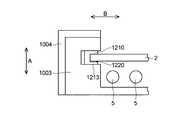
- the liquid crystal display device according to the sixth modification of the present invention shown in FIG. 20 may be configured. That is, as shown in FIG. 20, for example, the holding member 1210 (back side holding portion 1213) and the liquid crystal display panel 2 are bonded between the holding member 1210 between the back side holding portion 1213 and the liquid crystal display panel 2.
- the adhesive layer 1220 may be provided. If comprised in this way, it can suppress more that the liquid crystal display panel 2 moves with respect to the holding member 1210.
- Liquid crystal display device 2 Liquid crystal display panel (display panel) 10, 110, 210, 310, 410, 510, 610, 710, 810, 910, 1010, 1210 Holding member 11, 111, 211, 311, 411, 511, 610a, 711, 811, 911 Front side holding part 12, 112, 212, 312, 412, 512, 610b, 712, 812, 912 Regulating part 13, 113, 213, 313, 413, 513, 610c, 713, 813, 913, 1213 Back side holding part 103 Backlight chassis (fixed) Element) 103a, 104a Engaging part (second engaging part) 104 Bezel (fixing member) 110a, 110b, 210a, 210b, 310a, 310b, 610d, 610e, 710a Protruding part (first engaging part) 411a Sponge member (first sponge member) 414a Sponge member (second sponge member)
Landscapes
- Physics & Mathematics (AREA)
- Nonlinear Science (AREA)
- Mathematical Physics (AREA)
- Chemical & Material Sciences (AREA)
- Crystallography & Structural Chemistry (AREA)
- General Physics & Mathematics (AREA)
- Optics & Photonics (AREA)
- Liquid Crystal (AREA)
Abstract
表示パネルが面方向に移動するのを抑制することが可能な表示装置を提供する。この液晶表示装置(1)は、液晶表示パネル(2)と、液晶表示パネルの縁部を保持する保持部材(10)とを備える。保持部材は、液晶表示パネルの前面側に配置される前面側保持部(11)と、液晶表示パネルの背面側に配置される背面側保持部(13)と、液晶表示パネルの側方に配置され、液晶表示パネルが面方向(B方向)に移動するのを規制する規制部(12)とを含む。前面側保持部、規制部および背面側保持部は、一体的に形成されている。
Description
この発明は、表示装置に関し、特に、表示パネルの縁部を保持する保持部材を備えた表示装置に関する。
従来、表示パネルの縁部を保持する保持部材を備えた表示装置が知られている。図21は、表示パネルの縁部を保持する保持部材を備えた従来の一例による表示装置の構造を示した断面図である。図22は、図21に示した従来の一例による表示装置の構造を示した拡大断面図である。
従来の一例による表示装置2001は、図21に示すように、表示パネル2002と、表示パネル2002の縁部を保持する保持部材2010と、保持部材2010を挟持するバックライトシャーシ2003およびベゼル2004と、バックライトシャーシ2003の凹部2003aに収納される複数の光源2005とを備えている。
保持部材2010は、図22に示すように、表示パネル2002の前面を押圧する押さえ部材(前面側保持部)2011と、表示パネル2002の背面に当接される支持部材(背面側保持部)2012とを含んでいる。そして、押さえ部材2011と支持部材2012とにより、表示パネル2002が保持されている。
なお、従来の一例による表示装置2001のように表示パネルの縁部を保持する保持部材を備えた表示装置は、例えば、特許文献1に開示されている。
しかしながら、従来の一例による表示装置2001では、振動等により、表示パネル2002が面方向に移動(位置ずれまたは脱落)する場合があるという問題点がある。特に、近年、表示パネルの大型化が進むにつれ、上記の問題点を解決することが可能な表示装置が要求されている。
この発明は、上記のような課題を解決するためになされたものであり、この発明の目的は、表示パネルが面方向に移動するのを抑制することが可能な表示装置を提供することである。
上記目的を達成するために、この発明の一の局面による表示装置は、表示パネルと、表示パネルの縁部を保持する保持部材とを備え、保持部材は、表示パネルの前面側に配置される前面側保持部と、表示パネルの背面側に配置される背面側保持部と、表示パネルの側方に配置され、表示パネルが表示パネルの面方向に移動するのを規制する規制部とを含み、前面側保持部、背面側保持部および規制部は、一体的に形成されている。
この一の局面による表示装置では、上記のように、保持部材に、表示パネルの側方に配置され、表示パネルが表示パネルの面方向に移動するのを規制する規制部を設けることによって、例えば前面側保持部および背面側保持部の摩擦係数が小さい場合であっても、規制部により、表示パネルが面方向に移動するのを規制することができる。すなわち、表示パネルが面方向に位置ずれまたは脱落するのを抑制することができる。
また、一の局面による表示装置では、上記のように、前面側保持部、背面側保持部および規制部を、一体的に形成することによって、保持部材の部品点数が増加するのを抑制することができ、表示装置の組立工程を簡略化することができる。
また、前面側保持部、背面側保持部および規制部を、一体的に形成することによって、例えば、前面側保持部および背面側保持部の少なくとも一方をベゼルやバックライトシャーシなどに固定すれば、規制部をベゼルやバックライトシャーシなどに固定しなくても、規制部が表示パネルの面方向に移動するのを抑制することができる。
上記一の局面による表示装置において、好ましくは、保持部材を固定するための固定部材をさらに備え、保持部材には、第1係合部が形成されており、固定部材には、第1係合部が係合され、保持部材が面方向に移動するのを抑制するための第2係合部が形成されている。このように構成すれば、保持部材が表示パネルの面方向に移動するのを抑制することができるので、保持部材(規制部)により、表示パネルが面方向に移動するのを容易に抑制することができる。
上記保持部材に第1係合部が形成されている表示装置において、好ましくは、第1係合部を、保持部材の前面側保持部および背面側保持部の少なくとも一方に形成してもよい。
上記一の局面による表示装置において、好ましくは、規制部は、前面側保持部および背面側保持部の少なくとも一方と同一の部材により形成されている。このように構成すれば、規制部と前面側保持部および背面側保持部の一方との間に接着層などを設ける必要がないので、保持部材を容易に製造することができる。
上記規制部が前面側保持部および背面側保持部の少なくとも一方と同一の部材により形成されている表示装置において、好ましくは、前面側保持部、規制部および背面側保持部は、同一の部材により形成されている。このように構成すれば、保持部材をより容易に製造することができる。また、前面側保持部、規制部および背面側保持部を接着層などを用いて一体的に形成する場合に比べて、保持部材の強度を向上させることができる。
上記一の局面による表示装置において、保持部材を、ウレタンフォームにより形成してもよい。
上記一の局面による表示装置において、好ましくは、保持部材は、放熱シートにより形成されている。このように構成すれば、表示パネルの熱を、保持部材を介して外部に放熱させることができるので、表示パネル(表示装置)が高温になるのを抑制することができる。
上記保持部材が放熱シートにより形成されている表示装置において、好ましくは、放熱シートには、金属粉末が含有されている。このように構成すれば、保持部材(放熱シート)に、電磁波を遮蔽する機能を付与することができるので、表示パネルで発生する電磁波を、保持部材により遮蔽することができる。これにより、表示パネルで発生する電磁波が外部に漏れるのを抑制することができ、EMI(Electro Magnetic Interference)を低減することができる。また、表示パネルで発生する電磁波を発生源(表示パネル)に近い位置で遮蔽することができるので、電磁波を効果的に遮蔽することができる。
上記一の局面による表示装置において、好ましくは、保持部材の外面上には、熱伝導シートが設けられている。このように構成すれば、表示パネルの熱を、保持部材および熱伝導シートを介して外部に放熱させることができるので、表示パネル(表示装置)が高温になるのを抑制することができる。
上記一の局面による表示装置において、好ましくは、保持部材に接触されるシャーシをさらに備え、シャーシの保持部材に接触される部分の少なくとも一部は、金属により形成されている。このように構成すれば、表示パネルの熱を、保持部材を介して金属製のシャーシに放熱させることができるので、表示パネル(表示装置)が高温になるのを抑制することができる。
上記一の局面による表示装置において、好ましくは、保持部材は、第1スポンジ部材と、第1スポンジ部材よりも高い弾性率を有する第2スポンジ部材とを含み、前面側保持部および背面側保持部の少なくとも一方は、第1スポンジ部材により形成されており、規制部は、第2スポンジ部材により形成されている。このように構成すれば、前面側保持部および背面側保持部(第1スポンジ部材)により表示パネルを保持しながら、規制部(第2スポンジ部材)により、表示パネルが面方向に移動するのを規制することができる。
上記一の局面による表示装置において、好ましくは、保持部材と表示パネルとの間には、保持部材と表示パネルとを接着するための接着層が設けられている。このように構成すれば、表示パネルが保持部材に対して移動するのをより抑制することができる。
上記一の局面による表示装置において、好ましくは、保持部材は、電磁波を遮蔽する機能を有する。このように構成すれば、表示パネルで発生する電磁波を、保持部材により遮蔽することができるので、表示パネルで発生する電磁波が外部に漏れるのを抑制することができ、EMIを低減することができる。また、表示パネルで発生する電磁波を発生源(表示パネル)に近い位置で遮蔽することができるので、電磁波を効果的に遮蔽することができる。
上記保持部材が電磁波を遮蔽する機能を有する表示装置において、好ましくは、保持部材は、導電布を含む。このように構成すれば、導電布により、容易に電磁波を遮蔽することができる。
以上のように、本発明によれば、表示パネルが面方向に移動するのを抑制することが可能な表示装置を容易に得ることができる。
以下、本発明の実施形態について図面を参照して説明する。なお、理解を容易にするために、断面図であってもハッチングを施さない場合や、断面図でなくてもハッチングを施す場合がある。
(第1実施形態)
図1~図3を参照して、本発明の第1実施形態による液晶表示装置1の構造について説明する。
図1~図3を参照して、本発明の第1実施形態による液晶表示装置1の構造について説明する。
本発明の第1実施形態による液晶表示装置1は、例えば液晶テレビジョン受像機(図示せず)などを構成するものである。また、液晶表示装置1は、図1に示すように、液晶表示パネル2と、液晶表示パネル2の縁部を保持する保持部材10と、保持部材10を挟持するバックライトシャーシ3およびベゼル4と、バックライトシャーシ3の凹部3aに収納される複数の光源5とによって構成されている。そして、バックライトシャーシ3および複数の光源5などによって、直下型のバックライト装置が構成されている。なお、液晶表示装置1は、本発明の「表示装置」の一例であり、液晶表示パネル2は、本発明の「表示パネル」の一例である。
液晶表示パネル2は、図示しない液晶層を挟み込む2つのガラス基板からなる。また、液晶表示パネル2には、複数の配線(図示せず)が設けられている。また、液晶表示パネル2は、光源5に照明されることにより、表示パネルとして機能する。
保持部材10は、液晶表示パネル2の4つの縁部(4辺)に設けられている。また、保持部材10は、液晶表示パネル2の縁部に沿った細長形状に形成されている。
また、保持部材10は、図2および図3に示すように断面的に見てコの字形状に形成されている。また、保持部材10は、液晶表示パネル2(図2参照)の縁部の前面(上面)側に配置される前面側保持部11と、液晶表示パネル2の側方に配置される規制部12と、液晶表示パネル2の縁部の背面(下面)側に配置される背面側保持部13とによって構成されている。
ここで、第1実施形態では、前面側保持部11、規制部12および背面側保持部13は、一体的に形成されている。具体的には、前面側保持部11、規制部12および背面側保持部13は、接着層などを用いることなく、1つの部材(同一の部材)により形成されている。
また、第1実施形態では、保持部材10は、例えば、ウレタンフォームにより形成されている。なお、保持部材10を、例えば、ポロン(登録商標)により形成すれば、保持部材10の摩擦係数を比較的大きくすることが可能である。
また、保持部材10(前面側保持部11および背面側保持部13)の前面(上面)および背面(下面)に接着層(図示せず)を設け、その接着層により、保持部材10をベゼル4およびバックライトシャーシ3に接着していてもよい。なお、保持部材10は、前面側保持部11、規制部12および背面側保持部13が一体的に形成されているので、保持部材10の前面および背面の一方のみに接着層を設け、その接着層により、保持部材10をベゼル4およびバックライトシャーシ3の一方のみに接着していてもよい。
また、保持部材10(前面側保持部11および背面側保持部13)は、ベゼル4およびバックライトシャーシ3に挟持されることにより、液晶表示パネル2を保持している。そして、前面側保持部11と背面側保持部13とによって、液晶表示パネル2の厚み方向(A方向)の移動が規制(抑制)されている。また、規制部12によって、液晶表示パネル2の面方向(A方向と直交するB方向)の移動が規制されている。
バックライトシャーシ3は、例えば樹脂製である。また、バックライトシャーシ3には、複数の光源5を収納する凹部3aが形成されている。なお、凹部3aには、光源5と液晶表示パネル2との間に、プリズムシートやレンズシートなどの光学シート(図示せず)が配置されていてもよいし、光源5の背面側に、反射シート(図示せず)が配置されていてもよい。
また、光源5は、例えば、蛍光ランプにより形成されている。なお、光源5は、蛍光ランプ以外の、例えばLED(Light Emitting Diode)などにより形成されていてもよい。
ベゼル4は、例えば、板金(金属)により形成されている。また、ベゼル4には、液晶表示パネル2の表示領域に対応する部分に、開口部4aが設けられている。
第1実施形態では、上記のように、保持部材10に、液晶表示パネル2の側方に配置され、液晶表示パネル2が面方向(B方向)に移動するのを規制する規制部12を設けることによって、保持部材10(前面側保持部11および背面側保持部13)の摩擦係数が小さい場合であっても、規制部12により、液晶表示パネル2が面方向に移動するのを規制することができる。すなわち、液晶表示パネル2が面方向に位置ずれまたは脱落するのを抑制することができる。
また、第1実施形態では、上記のように、前面側保持部11、規制部12および背面側保持部13を、一体的に形成することによって、保持部材10の部品点数が増加するのを抑制することができ、液晶表示装置1の組立工程を簡略化することができる。
また、前面側保持部11、規制部12および背面側保持部13を、一体的に形成することによって、例えば、前面側保持部11および背面側保持部13の一方をベゼル4やバックライトシャーシ3に固定すれば、規制部12をベゼル4やバックライトシャーシ3に固定しなくても、規制部12が液晶表示パネル2の面方向に移動するのを抑制することができる。
また、第1実施形態では、上記のように、前面側保持部11、規制部12および背面側保持部13を、1つ(同一)の部材により形成することによって、前面側保持部11と規制部12との間や、規制部12と背面側保持部13との間に接着層などを設ける必要がないので、保持部材10を容易に製造することができる。また、前面側保持部11、規制部12および背面側保持部13を、接着層などを用いて一体的に形成する場合に比べて、保持部材10の強度を向上させることができる。
また、第1実施形態では、上記のように、保持部材10をポロン(登録商標)により形成すれば、保持部材10の摩擦係数を比較的大きくすることができるので、液晶表示パネル2が面方向に移動するのをより抑制することができる。
(第2実施形態)
この第2実施形態では、図4~図6を参照して、上記第1実施形態と異なり、保持部材110に突起部110aおよび110bを設ける場合について説明する。
この第2実施形態では、図4~図6を参照して、上記第1実施形態と異なり、保持部材110に突起部110aおよび110bを設ける場合について説明する。
第2実施形態では、図4および図5に示すように、保持部材110は、液晶表示パネル2(図4参照)の前面側に配置される前面側保持部111と、液晶表示パネル2の側方に配置される規制部112と、液晶表示パネル2の背面側に配置される背面側保持部113とによって構成されている。
ここで、第2実施形態では、前面側保持部111には、ベゼル104(図4参照)側に突出する突起部110aが形成されている。なお、ベゼル104は、本発明の「固定部材」の一例であり、突起部110aは、本発明の「第1係合部」の一例である。
また、背面側保持部113には、バックライトシャーシ103(図4参照)側に突出する突起部110bが形成されている。なお、バックライトシャーシ103は、本発明の「固定部材」の一例であり、突起部110bは、本発明の「第1係合部」の一例である。
また、第2実施形態では、図4および図6に示すように、ベゼル104には、保持部材110(図4参照)の突起部110aに係合する凹状の係合部(凹部)104aが形成されている。なお、係合部104aは、本発明の「第2係合部」の一例である。
また、バックライトシャーシ103には、保持部材110(図4参照)の突起部110bに係合する凹状の係合部(凹部)103aが形成されている。なお、係合部103aは、本発明の「第2係合部」の一例である。
第2実施形態のその他の構造は、上記第1実施形態と同様である。
第2実施形態では、上記のように、前面側保持部111に、突起部110aを形成し、ベゼル104に、突起部110aが係合される係合部104aを形成することによって、保持部材110が液晶表示パネル2の面方向(B方向)に移動するのを抑制することができる。これにより、保持部材110により、液晶表示パネル2が面方向(B方向)に移動するのを容易に規制することができる。
同様に、背面側保持部113に、突起部110bを形成し、バックライトシャーシ103に、突起部110bが係合される係合部103aを形成することによって、保持部材110が液晶表示パネル2の面方向(B方向)に移動するのをより抑制することができる。
なお、第2実施形態のその他の効果は、上記第1実施形態と同様である。
(第3実施形態)
この第3実施形態では、図7を参照して、上記第1および第2実施形態と異なり、保持部材210の前面側保持部211と規制部212との間に接着層220が設けられている場合について説明する。
この第3実施形態では、図7を参照して、上記第1および第2実施形態と異なり、保持部材210の前面側保持部211と規制部212との間に接着層220が設けられている場合について説明する。
第3実施形態では、図7に示すように、保持部材210は、液晶表示パネル2の前面側に配置される前面側保持部211と、液晶表示パネル2の側方に配置される規制部212と、液晶表示パネル2の背面側に配置される背面側保持部213とを含んでいる。
ここで、第3実施形態では、規制部212と背面側保持部213とは、接着層などを用いることなく、1つ(同一)の部材214により形成されている。その一方、前面側保持部211と規制部212との間には、接着層220が設けられており、この接着層220により、前面側保持部211と規制部212(部材214)とが固定されている。このようにして、前面側保持部211、規制部212および背面側保持部213が一体的に形成されている。
また、前面側保持部211には、ベゼル104側に突出する突起部210aが形成されており、背面側保持部213には、バックライトシャーシ103側に突出する突起部210bが形成されている。なお、突起部210aおよび210bは、本発明の「第1係合部」の一例である。
なお、第3実施形態のその他の構造および効果は、上記第1および第2実施形態と同様である。
(第4実施形態)
この第4実施形態では、図8を参照して、上記第1~第3実施形態と異なり、保持部材310が略U字形状に形成されている場合について説明する。
この第4実施形態では、図8を参照して、上記第1~第3実施形態と異なり、保持部材310が略U字形状に形成されている場合について説明する。
第4実施形態では、図8に示すように、保持部材310は、断面的に見て略U字形状に形成されている。また、保持部材310は、液晶表示パネル2の前面側に配置される前面側保持部311と、液晶表示パネル2の側方に配置される規制部312と、液晶表示パネル2の背面側に配置される背面側保持部313とによって構成されている。
また、前面側保持部311、規制部312および背面側保持部313は、接着層などを用いることなく、1つの部材(同一の部材)により形成されている。
そして、前面側保持部311には、ベゼル104側に突出する突起部310aが形成されており、背面側保持部313には、バックライトシャーシ103側に突出する突起部310bが形成されている。なお、突起部310aおよび310bは、本発明の「第1係合部」の一例である。
また、保持部材310は、例えば、ウレタンゴムやシリコーンゴムなどの、比較的低い弾性率を有するゴムシートにより形成されている。なお、保持部材310は、例えばポロン(登録商標)などのウレタンフォームにより形成されていてもよい。
第4実施形態のその他の構造および効果は、上記第1~第3実施形態と同様である。
(第5実施形態)
この第5実施形態では、図9~図11を参照して、上記第1~第4実施形態と異なり、保持部材410の前面側保持部411と規制部412とが、互いに異なる弾性率を有するように形成されている場合について説明する。
この第5実施形態では、図9~図11を参照して、上記第1~第4実施形態と異なり、保持部材410の前面側保持部411と規制部412とが、互いに異なる弾性率を有するように形成されている場合について説明する。
第5実施形態では、図9に示すように、保持部材410は、液晶表示パネル2の前面側に配置される前面側保持部411と、液晶表示パネル2の側方に配置される規制部412と、背面側保持部413とを含んでいる。
規制部412と背面側保持部413とは、接着層などを用いることなく、1つ(同一)の部材414により形成されている。その一方、前面側保持部411と規制部412(部材414)との間には、接着層420が設けられており、この接着層420により、前面側保持部411と規制部412(部材414)とが固定されている。このようにして、前面側保持部411、規制部412および背面側保持部413が一体的に形成されている。
また、接着層420は、前面側保持部411と規制部412(部材414)との境界面の一部に設けられている。なお、接着層420は、前面側保持部411と規制部412(部材414)との境界面の全面に設けられていてもよい。
ここで、第5実施形態では、図10に示すように、前面側保持部411および部材414(規制部412、背面側保持部413)は、それぞれ、スポンジ部材411aおよび414aにより形成されている。このスポンジ部材411aおよび414aは、例えば、ウレタンフォームなどの発泡体により形成されている。なお、スポンジ部材411aは、本発明の「第1スポンジ部材」の一例であり、スポンジ部材414aは、本発明の「第2スポンジ部材」の一例である。
また、規制部412(部材414)のスポンジ部材414aは、前面側保持部411のスポンジ部材411aよりも高い弾性率を有する。逆に言うと、前面側保持部411のスポンジ部材411aは、規制部412(部材414)のスポンジ部材414aよりも低い弾性率を有する。
このため、図11に示すように、前面側保持部411および部材414により液晶表示パネル2を挟み込んだ状態では、前面側保持部411は、圧縮されている。そして、前面側保持部411の反発力により、液晶表示パネル2が保持されている。
また、規制部412(部材414)のスポンジ部材414a(図10参照)は、前面側保持部411のスポンジ部材411a(図10参照)よりも高い弾性率を有するので、振動などにより液晶表示パネル2が面方向(B方向)に移動しようとした場合に、規制部412が圧縮されるのを抑制することが可能である。すなわち、液晶表示パネル2が面方向(B方向)に移動するのを規制することが可能である。
また、第5実施形態では、規制部412(部材414)のスポンジ部材414aを、前面側保持部411のスポンジ部材411aよりも高い弾性率を有するように形成するために、規制部412(部材414)のスポンジ部材414aを、前面側保持部411のスポンジ部材411aよりも小さい発泡率で形成している。
また、保持部材410の前面(上面)や背面(下面)に接着層(図示せず)を設け、その接着層により、保持部材410をベゼル4やバックライトシャーシ3に接着していてもよい。なお、部材414のスポンジ部材414aが十分に高い弾性率を有する場合には、部材414に、突起部を形成してもよい。
第5実施形態のその他の構造および効果は、上記第1~第4実施形態と同様である。
(第6実施形態)
この第6実施形態では、図12および図13を参照して、上記第1~第5実施形態と異なり、保持部材510が電磁波を遮蔽する機能を有する場合について説明する。
この第6実施形態では、図12および図13を参照して、上記第1~第5実施形態と異なり、保持部材510が電磁波を遮蔽する機能を有する場合について説明する。
第6実施形態では、図12に示すように、保持部材510は、例えばガスケットにより形成されている。具体的には、保持部材510は、芯材として用いられるコの字形状のスポンジ部材510aと、スポンジ部材510aを包み込む導電布510bとにより形成されている。そして、保持部材510の前面側保持部511(図13参照)、規制部512および背面側保持部513は、同一の部材(スポンジ部材510aおよび導電布510b)により形成されている。
スポンジ部材510aは、例えば、ウレタンフォームなどの発泡体により形成されている。
導電布510bは、例えば、ポリエステル織布に金属メッキなどを施した導電性繊維により形成されており、電磁波を遮蔽する機能を有する。このため、保持部材510の前面側保持部511(図13参照)、規制部512および背面側保持部513は、電磁波を遮蔽する機能を有する。
なお、導電布510bの前面側や背面側に接着層(図示せず)を設け、その接着層により、保持部材510をベゼル4やバックライトシャーシ3に接着していてもよい。
第6実施形態のその他の構造は、上記第1~第5実施形態と同様である。
第6実施形態では、上記のように、保持部材510を、電磁波を遮蔽する機能を有するように形成することによって、液晶表示パネル2で発生する電磁波を、保持部材510により遮蔽することができるので、液晶表示パネル2で発生する電磁波が外部に漏れるのを抑制することができ、EMIを低減することができる。また、液晶表示パネル2で発生する電磁波を発生源(液晶表示パネル2)に近い位置で遮蔽することができるので、電磁波を効果的に遮蔽することができる。
また、第6実施形態では、上記のように、保持部材510を、導電布510bを用いて形成することによって、導電布510bにより、容易に電磁波を遮蔽することができる。
なお、第6実施形態のその他の効果は、上記第1~第5実施形態と同様である。
(第7実施形態)
この第7実施形態では、図14を参照して、上記第6実施形態と異なり、保持部材610がゴムシート611と導電布612とにより構成されている場合について説明する。
この第7実施形態では、図14を参照して、上記第6実施形態と異なり、保持部材610がゴムシート611と導電布612とにより構成されている場合について説明する。
第7実施形態では、図14に示すように、保持部材610は、ゴムシート611と、ゴムシート611の外面に配置された導電布612とにより構成されている。そして、保持部材610の後述する前面側保持部610a、規制部610bおよび背面側保持部610cは、同一の部材(ゴムシート611および導電布612)により形成されている。
ゴムシート611は、例えば、ウレタンゴムやシリコーンゴムなどの、比較的低い弾性率を有する部材により形成されている。また、ゴムシート611は、例えば、約1mm~約2mmの厚みを有する。また、ゴムシート611は、断面的に見て略U字形状に形成されており、液晶表示パネル2の前面側に配置される部分611aと、液晶表示パネル2の側方に配置される部分611bと、液晶表示パネル2の背面側に配置される部分611cとを含んでいる。
導電布612は、ゴムシート611と同様、断面的に見て略U字形状に形成されており、液晶表示パネル2の前面側に配置される部分612aと、液晶表示パネル2の側方に配置される部分612bと、液晶表示パネル2の背面側に配置される部分612cとを含んでいる。
そして、ゴムシート611の部分611aと導電布612の部分612aとにより、液晶表示パネル2の縁部の前面を押圧する前面側保持部610aが構成されている。また、ゴムシート611の部分611bと導電布612の部分612bとにより、液晶表示パネル2が面方向(B方向)に移動するのを規制する規制部610bが構成されている。また、ゴムシート611の部分611cと導電布612の部分612cとにより、液晶表示パネル2の背面に当接される背面側保持部610cが構成されている。
なお、ゴムシート611と導電布612との間に接着層(図示せず)を設け、その接着層により、導電布612をゴムシート611に接着していてもよい。
ここで、第7実施形態では、ゴムシート611の部分611aには、ベゼル側に突出する凸部611dが形成されている。このため、ゴムシート611の部分611aを覆う導電布612の部分612aにも、凸部612dが形成されている。そして、ゴムシート611の凸部611dと導電布612の凸部612dとにより、突起部610dが形成されている。なお、突起部610dは、本発明の「第1係合部」の一例である。
同様に、ゴムシート611の部分611cには、バックライトシャーシ側に突出する凸部611eが形成されている。このため、ゴムシート611の部分611cを覆う導電布612の部分612cにも、凸部612eが形成されている。そして、ゴムシート611の凸部611eと導電布612の凸部612eとにより、突起部610eが形成されている。なお、突起部610eは、本発明の「第1係合部」の一例である。
第7実施形態のその他の構造は、上記第4および第6実施形態と同様である。
また、第7実施形態の効果は、上記第1~第6実施形態と同様である。
なお、今回開示された実施形態は、すべての点で例示であって制限的なものではないと考えられるべきである。本発明の範囲は、上記した実施形態の説明ではなく請求の範囲によって示され、さらに請求の範囲と均等の意味および範囲内でのすべての変更が含まれる。
例えば、上記実施形態では、表示パネルおよび表示装置を、液晶表示パネルおよび液晶表示装置に適用した例について示したが、本発明はこれに限らず、液晶表示装置以外の表示装置に適用してもよい。
また、本発明は、小型の表示装置および大型の表示装置の両方に適用可能であるが、大型の表示パネルは、重い表示パネルを保持する構造が重要であるので、本発明を大型の表示装置に適用するのは、特に有効である。
また、上記実施形態では、液晶表示装置が直下型のバックライト装置により形成されている例について示したが、本発明はこれに限らず、液晶表示装置を、サイドライト型のバックライト装置により形成してもよい。この場合、光源からの光を導光する導光板(導光部材)を設けてもよい。
また、上記実施形態では、スポンジ部材を、ウレタンフォームにより形成した例について示したが、本発明はこれに限らず、スポンジ部材を、ウレタンフォーム以外の、例えばゴムや樹脂等により形成してもよい。
また、例えば上記第2実施形態等では、保持部材の前面側保持部および背面側保持部の両方に突起部を設けた例について示したが、本発明はこれに限らず、保持部材の前面側保持部および背面側保持部のいずれか一方のみに突起部を設けてもよい。例えば、図15に示した本発明の第1変形例による保持部材710のように構成してもよい。すなわち、保持部材710を、前面側保持部711、規制部712および背面側保持部713によって構成し、例えば前面側保持部711のみに突起部(第1係合部)710aを形成してもよい。
また、例えば上記第2実施形態等では、保持部材に突起部を設け、ベゼルおよびバックライトシャーシに係合部(凹部)を設けた例について示したが、本発明はこれに限らず、例えば図16に示した本発明の第2変形例による保持部材810のように構成してもよい。すなわち、保持部材810を、前面側保持部811、規制部812および背面側保持部813によって構成し、前面側保持部811および背面側保持部813に凹状の係合部(第1係合部)810aおよび810bを設けてもよい。この場合、ベゼルおよびバックライトシャーシに突起部(第2係合部)を設ければよい。
また、上記実施形態では、前面側保持部、規制部および背面側保持部を、1つまたは2つの部材で構成した例について示したが、本発明はこれに限らず、例えば図17に示した本発明の第3変形例による保持部材910のように、前面側保持部911、規制部912および背面側保持部913を、3つ以上の部材で構成してもよい。そして、前面側保持部911と規制部912との間に接着層920を配置し、接着層920により前面側保持部911と規制部912とを接着してもよい。また、規制部912と背面側保持部913との間に接着層921を配置し、接着層921により規制部912と背面側保持部913とを接着してもよい。
また、上記第5実施形態では、規制部のスポンジ部材を、前面側保持部のスポンジ部材よりも高い弾性率を有するように形成するために、規制部のスポンジ部材を、前面側保持部のスポンジ部材よりも小さい発泡率で形成した例について示したが、本発明はこれに限らず、規制部のスポンジ部材と、前面側保持部のスポンジ部材とを異なる材料を用いて形成することにより、規制部のスポンジ部材を、前面側保持部のスポンジ部材よりも高い弾性率を有するように形成してもよい。
また、本発明では、保持部材を、放熱シートにより形成してもよい。このように構成すれば、液晶表示パネルの熱(液晶表示パネルで発生した熱や、光源で発生し液晶表示パネルに伝達された熱)を、保持部材を介して外部(ベゼルやバックライトシャーシ)に放熱させることができる。これにより、液晶表示パネル(液晶表示装置)が高温になるのを抑制することができる。なお、保持部材に用いる放熱シートは、アスカーC硬度で、例えば約40度~約60度程度の硬度を有することが好ましい。
また、放熱シート(保持部材)は、例えばフェライトなどの金属粉末が含有されていてもよい。このように構成すれば、放熱シート(保持部材)に、電磁波を遮蔽する機能を付与することができるので、液晶表示パネルで発生する電磁波を、放熱シート(保持部材)により遮蔽することができる。
また、上記実施形態では、保持部材の外面上に、熱伝導シートを設けていない例について示したが、本発明はこれに限らず、保持部材の外面上に、熱伝導性が良好な熱伝導シートを設けてもよい。この場合、例えば、図18に示した本発明の第4変形例による液晶表示装置のように構成してもよい。すなわち、図18に示すように、バックライトシャーシ1003を、A方向の両側から保持部材1010を挟み込むように形成し、ベゼル1004を、バックライトシャーシ1003の外面上に配置してもよい。そして、保持部材1010とバックライトシャーシ1003との間に、例えばアルミニウム合金などからなる熱伝導シート1020を配置する。また、この熱伝導シート1020を、ベゼル1004に接触するように配置する。このように構成すれば、液晶表示パネル2の熱を、保持部材1010および熱伝導シート1020を介して、外部(ベゼル1004)に放熱させることができる。なお、保持部材1010と熱伝導シート1020とを、接着層(図示せず)などを介して一体的に形成してもよい。
また、図19に示した本発明の第5変形例による液晶表示装置のように、バックライトシャーシ1103の、保持部材1010に接触される部分の一部1103a(またはバックライトシャーシ1103の全て)を金属により形成してもよい。このように構成しても、液晶表示パネル2の熱を、保持部材1010を介して、外部(バックライトシャーシ1103およびベゼル1004)に放熱させることができる。
また、上記実施形態では、保持部材と液晶表示パネルとの間に接着層を設けていない例について示したが、本発明はこれに限らず、保持部材と液晶表示パネルとの間に接着層を設けてもよい。この場合、例えば、図20に示した本発明の第6変形例による液晶表示装置のように構成してもよい。すなわち、図20に示すように、保持部材1210の、例えば背面側保持部1213と液晶表示パネル2との間に、保持部材1210(背面側保持部1213)と液晶表示パネル2とを接着するための接着層1220を設けてもよい。このように構成すれば、液晶表示パネル2が保持部材1210に対して移動するのをより抑制することができる。
1 液晶表示装置(表示装置)
2 液晶表示パネル(表示パネル)
10、110、210、310、410、510、610、710、810、910、1010、1210 保持部材
11、111、211、311、411、511、610a、711、811、911 前面側保持部
12、112、212、312、412、512、610b、712、812、912 規制部
13、113、213、313、413、513、610c、713、813、913、1213 背面側保持部
103 バックライトシャーシ(固定部材)
103a、104a 係合部(第2係合部)
104 ベゼル(固定部材)
110a、110b、210a、210b、310a、310b、610d、610e、710a 突起部(第1係合部)
411a スポンジ部材(第1スポンジ部材)
414a スポンジ部材(第2スポンジ部材)
510b、612 導電布
810a、810b 係合部(第1係合部)
1103 バックライトシャーシ(シャーシ)
1103a 一部
1020 熱伝導シート
1220 接着層
2 液晶表示パネル(表示パネル)
10、110、210、310、410、510、610、710、810、910、1010、1210 保持部材
11、111、211、311、411、511、610a、711、811、911 前面側保持部
12、112、212、312、412、512、610b、712、812、912 規制部
13、113、213、313、413、513、610c、713、813、913、1213 背面側保持部
103 バックライトシャーシ(固定部材)
103a、104a 係合部(第2係合部)
104 ベゼル(固定部材)
110a、110b、210a、210b、310a、310b、610d、610e、710a 突起部(第1係合部)
411a スポンジ部材(第1スポンジ部材)
414a スポンジ部材(第2スポンジ部材)
510b、612 導電布
810a、810b 係合部(第1係合部)
1103 バックライトシャーシ(シャーシ)
1103a 一部
1020 熱伝導シート
1220 接着層
Claims (14)
- 表示パネルと、
前記表示パネルの縁部を保持する保持部材とを備え、
前記保持部材は、
前記表示パネルの前面側に配置される前面側保持部と、
前記表示パネルの背面側に配置される背面側保持部と、
前記表示パネルの側方に配置され、前記表示パネルが前記表示パネルの面方向に移動するのを規制する規制部とを含み、
前記前面側保持部、前記背面側保持部および前記規制部は、一体的に形成されていることを特徴とする表示装置。 - 前記保持部材を固定するための固定部材をさらに備え、
前記保持部材には、第1係合部が形成されており、
前記固定部材には、前記第1係合部が係合され、前記保持部材が前記面方向に移動するのを抑制するための第2係合部が形成されていることを特徴とする請求項1に記載の表示装置。 - 前記第1係合部は、前記保持部材の前記前面側保持部および前記背面側保持部の少なくとも一方に形成されていることを特徴とする請求項2に記載の表示装置。
- 前記規制部は、前記前面側保持部および前記背面側保持部の少なくとも一方と同一の部材により形成されていることを特徴とする請求項1~3のいずれか1項に記載の表示装置。
- 前記前面側保持部、前記規制部および前記背面側保持部は、同一の部材により形成されていることを特徴とする請求項4に記載の表示装置。
- 前記保持部材は、ウレタンフォームにより形成されていることを特徴とする請求項1~5のいずれか1項に記載の表示装置。
- 前記保持部材は、放熱シートにより形成されていることを特徴とする請求項1~6のいずれか1項に記載の表示装置。
- 前記放熱シートには、金属粉末が含有されていることを特徴とする請求項7に記載の表示装置。
- 前記保持部材の外面上には、熱伝導シートが設けられていることを特徴とする請求項1~8のいずれか1項に記載の表示装置。
- 前記保持部材に接触されるシャーシをさらに備え、
前記シャーシの前記保持部材に接触される部分の少なくとも一部は、金属により形成されていることを特徴とする請求項1~9のいずれか1項に記載の表示装置。 - 前記保持部材は、第1スポンジ部材と、前記第1スポンジ部材よりも高い弾性率を有する第2スポンジ部材とを含み、
前記前面側保持部および前記背面側保持部の少なくとも一方は、前記第1スポンジ部材により形成されており、
前記規制部は、前記第2スポンジ部材により形成されていることを特徴とする請求項1~10のいずれか1項に記載の表示装置。 - 前記保持部材と前記表示パネルとの間には、前記保持部材と前記表示パネルとを接着するための接着層が設けられていることを特徴とする請求項1~11のいずれか1項に記載の表示装置。
- 前記保持部材は、電磁波を遮蔽する機能を有することを特徴とする請求項1~12のいずれか1項に記載の表示装置。
- 前記保持部材は、導電布を含むことを特徴とする請求項13に記載の表示装置。
Applications Claiming Priority (2)
| Application Number | Priority Date | Filing Date | Title |
|---|---|---|---|
| JP2010123256 | 2010-05-28 | ||
| JP2010-123256 | 2010-05-28 |
Publications (1)
| Publication Number | Publication Date |
|---|---|
| WO2011148656A1 true WO2011148656A1 (ja) | 2011-12-01 |
Family
ID=45003651
Family Applications (1)
| Application Number | Title | Priority Date | Filing Date |
|---|---|---|---|
| PCT/JP2011/050235 Ceased WO2011148656A1 (ja) | 2010-05-28 | 2011-01-11 | 表示装置 |
Country Status (1)
| Country | Link |
|---|---|
| WO (1) | WO2011148656A1 (ja) |
Cited By (3)
| Publication number | Priority date | Publication date | Assignee | Title |
|---|---|---|---|---|
| WO2014076998A1 (en) * | 2012-11-15 | 2014-05-22 | Kabushiki Kaisha Toshiba | Grounding gasket and electronic apparatus |
| US9078351B2 (en) | 2012-11-15 | 2015-07-07 | Kabushiki Kaisha Toshiba | Grounding gasket and electronic apparatus |
| WO2017038519A1 (ja) * | 2015-08-28 | 2017-03-09 | シャープ株式会社 | 液晶表示装置 |
Citations (6)
| Publication number | Priority date | Publication date | Assignee | Title |
|---|---|---|---|---|
| JP2000181371A (ja) * | 1998-12-11 | 2000-06-30 | Nec Corp | 液晶モジュール支持構造及びこれを搭載する携帯用端末装置 |
| JP2003031162A (ja) * | 2001-07-17 | 2003-01-31 | Canon Inc | アノード端子と高圧トランスとの一体構造を有する画像表示装置 |
| JP2003202550A (ja) * | 2002-01-08 | 2003-07-18 | Hitachi Ltd | 液晶表示装置 |
| JP2004029455A (ja) * | 2002-06-26 | 2004-01-29 | Nec Viewtechnology Ltd | 液晶表示装置および液晶プロジェクタ装置 |
| JP2005077590A (ja) * | 2003-08-29 | 2005-03-24 | Hitachi Displays Ltd | 画像表示装置 |
| JP2005114851A (ja) * | 2003-10-03 | 2005-04-28 | Sony Corp | 電子機器の放熱機構 |
-
2011
- 2011-01-11 WO PCT/JP2011/050235 patent/WO2011148656A1/ja not_active Ceased
Patent Citations (6)
| Publication number | Priority date | Publication date | Assignee | Title |
|---|---|---|---|---|
| JP2000181371A (ja) * | 1998-12-11 | 2000-06-30 | Nec Corp | 液晶モジュール支持構造及びこれを搭載する携帯用端末装置 |
| JP2003031162A (ja) * | 2001-07-17 | 2003-01-31 | Canon Inc | アノード端子と高圧トランスとの一体構造を有する画像表示装置 |
| JP2003202550A (ja) * | 2002-01-08 | 2003-07-18 | Hitachi Ltd | 液晶表示装置 |
| JP2004029455A (ja) * | 2002-06-26 | 2004-01-29 | Nec Viewtechnology Ltd | 液晶表示装置および液晶プロジェクタ装置 |
| JP2005077590A (ja) * | 2003-08-29 | 2005-03-24 | Hitachi Displays Ltd | 画像表示装置 |
| JP2005114851A (ja) * | 2003-10-03 | 2005-04-28 | Sony Corp | 電子機器の放熱機構 |
Cited By (3)
| Publication number | Priority date | Publication date | Assignee | Title |
|---|---|---|---|---|
| WO2014076998A1 (en) * | 2012-11-15 | 2014-05-22 | Kabushiki Kaisha Toshiba | Grounding gasket and electronic apparatus |
| US9078351B2 (en) | 2012-11-15 | 2015-07-07 | Kabushiki Kaisha Toshiba | Grounding gasket and electronic apparatus |
| WO2017038519A1 (ja) * | 2015-08-28 | 2017-03-09 | シャープ株式会社 | 液晶表示装置 |
Similar Documents
| Publication | Publication Date | Title |
|---|---|---|
| JP4945325B2 (ja) | 液晶表示装置 | |
| JP6374323B2 (ja) | 表示装置 | |
| US9195087B2 (en) | Display device and television device | |
| US8870437B2 (en) | Lighting device, display device, and television receiver | |
| JP4713622B2 (ja) | 液晶表示装置及びこれを用いた映像表示装置 | |
| US9995871B2 (en) | Light-source device and liquid crystal display apparatus | |
| WO2011093121A1 (ja) | 照明装置、表示装置およびテレビ受信装置 | |
| JP6234377B2 (ja) | 表示装置 | |
| CN101813837A (zh) | 液晶显示装置 | |
| JP5845795B2 (ja) | 表示装置 | |
| JP5468692B1 (ja) | 液晶表示装置 | |
| JP2013004783A (ja) | 放熱構造および表示装置 | |
| US20140247398A1 (en) | Display | |
| JP5064602B2 (ja) | 表示装置 | |
| JP2011253769A (ja) | バックライトモジュールおよび液晶表示装置 | |
| CN108267889B (zh) | 液晶显示器 | |
| WO2012035894A1 (ja) | 表示装置、液晶表示装置、および、テレビジョン受信機 | |
| JPWO2010087052A1 (ja) | 照明装置及び液晶表示装置 | |
| WO2012036061A1 (ja) | 照明装置、表示装置およびテレビジョン受像機 | |
| WO2011148656A1 (ja) | 表示装置 | |
| JP2014153437A (ja) | 表示装置 | |
| WO2011148666A1 (ja) | 表示装置 | |
| WO2013005554A1 (ja) | 光学シート、バックライト装置及び液晶表示装置 | |
| US20180217321A1 (en) | Planar light source device and display device | |
| US10712491B2 (en) | Display |
Legal Events
| Date | Code | Title | Description |
|---|---|---|---|
| 121 | Ep: the epo has been informed by wipo that ep was designated in this application |
Ref document number: 11786356 Country of ref document: EP Kind code of ref document: A1 |
|
| NENP | Non-entry into the national phase |
Ref country code: DE |
|
| 122 | Ep: pct application non-entry in european phase |
Ref document number: 11786356 Country of ref document: EP Kind code of ref document: A1 |
|
| NENP | Non-entry into the national phase |
Ref country code: JP |