図面のFIG.1を参照すると、双極型二次電池100は、略矩形横断面のケース103と、ケース103の相対する2つの辺を介してケース103の内側から外側へ取り出される正極集電板101と負極集電板102とを備える。
Fig. Of the drawing. 1, a bipolar secondary battery 100 includes a case 103 having a substantially rectangular cross section, and a positive current collector 101 and a negative current collector that are taken out from the inside of the case 103 through two opposite sides of the case 103. And an electric plate 102.
FIG.2を参照すると、双極型二次電池100は、ケース103の内側に電池本体300を備える。電池本体300は複数のセル26を積層した積層体30を2個直列接続することで構成される。セル26は例えばリチウムイオンセルで構成される。正極集電板101と負極集電板102は電池本体300を挟持する形で、ケース103の内周面に固定される。
FIG. 2, the bipolar secondary battery 100 includes a battery body 300 inside the case 103. The battery body 300 is configured by connecting two stacked bodies 30 in which a plurality of cells 26 are stacked in series. The cell 26 is composed of, for example, a lithium ion cell. The positive electrode current collector plate 101 and the negative electrode current collector plate 102 are fixed to the inner peripheral surface of the case 103 so as to sandwich the battery body 300.
ケース103は、電池本体300を外気から遮断し、電池本体300を保護する役割を持つ。ケース103は一対のケース部材103aと103bからなる。ケース部材103aと103bは、電池本体300を収容する凹部と凹部を囲むフランジ部とをそれぞれ有する
The case 103 has a role of blocking the battery body 300 from outside air and protecting the battery body 300. The case 103 includes a pair of case members 103a and 103b. Case members 103a and 103b each have a recess for housing battery main body 300 and a flange portion surrounding the recess.
ケース103は、ケース103の内側から外側へ至る正極集電板101と負極集電板102とを挟む形で、一対のケース部材103aと103bのフランジ部同士を溶着させることで一体に構成される。ケース103には内外に生じる圧力差に対して積層体30を損傷させない強度と、変形可能な可撓性とを備えたシート状素材が用いられる。シート状素材は、さらに電解液や気体を透過させず、電気絶縁性を有し、電解液などの材料に対して化学的に安定であることが望ましい。
The case 103 is integrally formed by welding the flange portions of the pair of case members 103a and 103b with the positive electrode current collecting plate 101 and the negative electrode current collecting plate 102 sandwiched between the inside and the outside of the case 103. . For the case 103, a sheet-like material having strength that does not damage the laminated body 30 against a pressure difference generated inside and outside, and deformable flexibility is used. It is desirable that the sheet-like material does not allow permeation of the electrolytic solution or gas, has electrical insulation, and is chemically stable with respect to the material such as the electrolytic solution.
シート状素材には、好ましくはラミネートフィルム、ポリエチレン、ポリプロピレン、ポリカーボネートなどが用いられる。ラミネートフィルムは、アルミニウム、ステンレス、ニッケル、銅などの合金を含む金属の金属箔を、ポリプロピレンフィルムなどの絶縁性の合成樹脂膜で被覆したものである。
For the sheet material, a laminate film, polyethylene, polypropylene, polycarbonate or the like is preferably used. The laminate film is obtained by coating a metal metal foil containing an alloy such as aluminum, stainless steel, nickel, or copper with an insulating synthetic resin film such as a polypropylene film.
積層体30を構成するセル26は、電解質層25と、電解質層25の両側に積層された正極活物質層23と負極活物質層24と、さらに積層方向に関して正極活物質層23と負極活物質層24の外側に積層された面積のより大きな板状の集電体22とで構成される。ただし、図に示すように複数のセル26を積層する場合には、集電体22は隣接するセル26の間に一枚のみ挟持される。
The cell 26 constituting the laminate 30 includes an electrolyte layer 25, a positive electrode active material layer 23 and a negative electrode active material layer 24 laminated on both sides of the electrolyte layer 25, and a positive electrode active material layer 23 and a negative electrode active material with respect to the lamination direction. The plate-like current collector 22 having a larger area laminated on the outside of the layer 24 is configured. However, when a plurality of cells 26 are stacked as shown in the figure, only one current collector 22 is sandwiched between adjacent cells 26.
集電体22には公知の材料か使用される。例えば、アルミニウムやステンレス(SUS)を使用することができる。集電体22の材料に高分子材料を含むこともできる。すなわち、ポリオレフィン(ポリプロピレン、ポリエチレン)、ポリエステル(PET、PEN)、ポリイミド、ポリアミド、ポリフッ化ビニリデン(PVdF)を用いることができる。これらの高分子材料に導電性をもたせるために、好ましくは高分子材料中にケッチェンブラック、アセチレンブラック、カーボンブラックなどのカーボンや、アルミニウム(Al)、銅(Cu)、ステンレス鋼(SUS)、チタニウム(Ti)などの金属、の粒子を分散させる。
A known material is used for the current collector 22. For example, aluminum or stainless steel (SUS) can be used. A polymer material may be included in the material of the current collector 22. That is, polyolefin (polypropylene, polyethylene), polyester (PET, PEN), polyimide, polyamide, and polyvinylidene fluoride (PVdF) can be used. In order to impart conductivity to these polymer materials, carbon such as ketjen black, acetylene black, carbon black, aluminum (Al), copper (Cu), stainless steel (SUS), Disperse particles of a metal such as titanium (Ti).
正極活物質層23は、正極活物質を含み、さらに導電助剤やバインダーなどを含み得る。正極活物質には、溶液系のリチウムイオン電池で使用される、遷移金属とリチウムとの複合酸化物を使用できる。
The positive electrode active material layer 23 includes a positive electrode active material, and may further include a conductive additive or a binder. As the positive electrode active material, a composite oxide of a transition metal and lithium used in a solution-type lithium ion battery can be used.
負極活物質層24は、負極活物質を含み、さらに導電助剤やバインダーなどを含み得る。負極活物質には、溶液系のリチウムイオン電池で使用される負極活物質を用いることができる。
The negative electrode active material layer 24 includes a negative electrode active material, and may further include a conductive additive or a binder. As the negative electrode active material, a negative electrode active material used in a solution-type lithium ion battery can be used.
特に、正極活物質層23の正極活物質にリチウム-遷移金属複合酸化物を用い、負極活物質層24の負極活物質にカーボンまたはリチウム-遷移金属複合酸化物を用いることで、容量と出力特性に優れた電池を構成することができる。
In particular, by using a lithium-transition metal composite oxide for the positive electrode active material of the positive electrode active material layer 23 and using carbon or a lithium-transition metal composite oxide for the negative electrode active material of the negative electrode active material layer 24, capacity and output characteristics can be obtained. It is possible to construct a battery excellent in the above.
電解質層25は、イオン伝導性を有する高分子を含む層または液体電解質で構成される。この実施例では電解質に、基材としてのセパレータにプレゲル溶液を含浸させた後、化学架橋または物理架橋により得た高分子ゲル電解質を用いている。電解質層25に含まれる電解液は、ポリプレンカーボネート、エチレンカーボネート、ジエチルカーボネート等の有機溶媒を含有し、温度上昇により沸騰してガス化する。セパレータをポリエチレン(PE)フィルムを用いる場合のセパレータの融点は摂氏134度(℃)である。電解液の沸点は140℃とする。
The electrolyte layer 25 is composed of a layer containing a polymer having ion conductivity or a liquid electrolyte. In this embodiment, a polymer gel electrolyte obtained by chemical crosslinking or physical crosslinking after impregnating a pregel solution into a separator as a base material is used as an electrolyte. The electrolytic solution contained in the electrolyte layer 25 contains an organic solvent such as polypropylene carbonate, ethylene carbonate, and diethyl carbonate, and boils and gasifies as the temperature rises. When a polyethylene (PE) film is used as the separator, the melting point of the separator is 134 degrees Celsius (° C.). The boiling point of the electrolyte is 140 ° C.
詳しくは後述するが、電解液は正極活物質層23と負極活物質層24の表面に塗布され、正極活物質層23と負極活物質層24をセパレータに重ね合わせることで、セパレータに含浸させる。なお、FIG.2は、電池本体300の構成を分かりやすく説明するために、細部の構造を省略している。具体的には、セパレータの図示が省略されている。
As will be described in detail later, the electrolytic solution is applied to the surfaces of the positive electrode active material layer 23 and the negative electrode active material layer 24, and the separator is impregnated by superimposing the positive electrode active material layer 23 and the negative electrode active material layer 24 on the separator. FIG. In FIG. 2, the detailed structure is omitted for easy understanding of the configuration of the battery body 300. Specifically, the illustration of the separator is omitted.
セル26の外周はシール部40に覆われる。シール部40は、隣接する集電体22の外周部の間に充填され、正極活物質層23と電解質層25と負極活物質層24の外気との接触を遮断する。シール部40はセル26を密封することにより、電解質のイオン伝導度の低下を防止する。また、液体または半固体のゲル状の電解質を使用する場合の、液漏れによる液絡を防止する。
The outer periphery of the cell 26 is covered with the seal portion 40. The seal portion 40 is filled between the outer peripheral portions of the adjacent current collectors 22 and blocks contact between the positive electrode active material layer 23, the electrolyte layer 25, and the outside air of the negative electrode active material layer 24. The seal part 40 seals the cell 26 to prevent a decrease in the ionic conductivity of the electrolyte. In addition, when a liquid or semi-solid gel electrolyte is used, liquid junction due to liquid leakage is prevented.
シール前駆体には、例えば加圧変形により集電体22に密着するゴム系樹脂、または加熱加圧して熱融着させることで集電体22に密着する熱融着可能な樹脂を使用することができる。
For the seal precursor, for example, a rubber-based resin that is in close contact with the current collector 22 by pressure deformation or a heat-sealable resin that is in close contact with the current collector 22 by heat-pressing and heat-sealing is used. Can do.
ゴム系樹脂には特に制限はないが、好ましくは、シリコン系ゴム、フッ素系ゴム、オレフィン系ゴム、ニトリル系ゴムよりなる群から選択される。これらのゴム系樹脂は、シール性、耐アルカリ性、耐薬品性、耐久性、耐候性、耐熱性などに優れ、二次電池の使用環境においてもこれらの優れた性能と品質を長期間維持することができる。
The rubber resin is not particularly limited, but is preferably selected from the group consisting of silicon rubber, fluorine rubber, olefin rubber, and nitrile rubber. These rubber-based resins have excellent sealing properties, alkali resistance, chemical resistance, durability, weather resistance, heat resistance, etc., and maintain these excellent performance and quality for a long time even in the usage environment of secondary batteries. Can do.
熱融着可能な樹脂は、積層体30のあらゆる使用環境下で優れたシール効果を発揮できるものが好ましい。熱融着可能な樹脂は、例えばシリコン、エポキシ、ウレタン、ポリブタジエン、オレフィン系樹脂(ポリプロピレン、ポリエチレンなど)、パラフィンワックスよりなる群から選択される。これらの熱融着可能な樹脂は、シール性、耐アルカリ性、耐薬品性、耐久性・耐候性、耐熱性などに優れ、二次電池の使用環境においても優れた性能と品質を長期間維持することができる。
The resin that can be heat-sealed is preferably a resin that can exhibit an excellent sealing effect under any usage environment of the laminate 30. The heat-sealable resin is selected from the group consisting of silicon, epoxy, urethane, polybutadiene, olefin resin (polypropylene, polyethylene, etc.), and paraffin wax, for example. These heat-sealable resins have excellent sealing performance, alkali resistance, chemical resistance, durability / weather resistance, heat resistance, etc., and maintain excellent performance and quality for a long time even in the usage environment of secondary batteries. be able to.
積層体30の製造プロセスにおいては、集電体22の一方の面に正極活物質層23を形成し、もう一方の面に負極活物質層24を形成した複数の双極型電極21と電解質層25とが交互に6層に渡って積層される。
In the manufacturing process of the laminated body 30, a plurality of bipolar electrodes 21 and an electrolyte layer 25 in which the positive electrode active material layer 23 is formed on one surface of the current collector 22 and the negative electrode active material layer 24 is formed on the other surface. Are alternately stacked over 6 layers.
積層方向に関する積層体30の両端には集電体22aと22bが積層される。集電体22と異なり、集電体22aは一方の面に正極活物質層23を形成し、もう一方の面には何も形成しない。集電体22bは一方の面に負極活物質層24を形成し、もう一方の面には何も形成しない。集電体22aは正極活物質層23を電解質層25に接した状態で積層される。集電体22bは負極活物質層24を電解質層25に接した状態で積層される。集電体22aは積層体30の正極を構成し、集電体22bは積層体30の負極を構成する。
Current collectors 22a and 22b are stacked on both ends of the stacked body 30 in the stacking direction. Unlike the current collector 22, the current collector 22a forms the positive electrode active material layer 23 on one surface and does not form anything on the other surface. In the current collector 22b, the negative electrode active material layer 24 is formed on one surface, and nothing is formed on the other surface. The current collector 22 a is laminated with the positive electrode active material layer 23 in contact with the electrolyte layer 25. The current collector 22 b is laminated with the negative electrode active material layer 24 in contact with the electrolyte layer 25. The current collector 22 a constitutes the positive electrode of the laminate 30, and the current collector 22 b constitutes the negative electrode of the laminate 30.
以上のようにして積層された6個のセル26を熱プレス機を用いてシール部40が所定の厚さとなるように熱プレスし、さらに未硬化のシール部40を硬化させることで双極型の積層体30が完成する。
The six cells 26 laminated as described above are hot-pressed using a hot press machine so that the seal portion 40 has a predetermined thickness, and the uncured seal portion 40 is cured, so that a bipolar type is obtained. The laminated body 30 is completed.
FIG.3を参照すると、電池本体300は、一方の積層体30の集電体22aともう一方の積層体30の集電体22bとの間に電流制御層50を挟持しつつ、直列に配置された2個の積層体30からなる。なお、この図は特徴を分かりやすく示すために、要部をデフォルメして描いている。
FIG. 3, the battery body 300 is arranged in series with the current control layer 50 sandwiched between the current collector 22a of one stacked body 30 and the current collector 22b of the other stacked body 30. It consists of two laminates 30. In this figure, the main part is drawn in a deformed manner for easy understanding of the features.
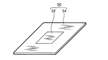
FIG.4を参照すると、電流制御層50は温度上昇に応じて電気抵抗が増大する感温抵抗52と、感温抵抗52の温度上昇時の抵抗よりさらに高い電気抵抗値を持つ電流遮断部54とからなる。
FIG. 4, the current control layer 50 includes a temperature-sensitive resistor 52 whose electric resistance increases as the temperature rises, and a current interrupting unit 54 having an electric resistance value higher than the resistance of the temperature-sensitive resistor 52 when the temperature rises. Become.
電流遮断部54は、隣接する集電体22a及び集電体22bと同等の外形寸法の高電気抵抗の板部材で構成される。電流遮断部54の中央部には矩形に切り欠かれ、切り欠かれた部分に感温抵抗52が嵌合する。
The current interrupting part 54 is composed of a plate member with a high electrical resistance having the same outer dimensions as the adjacent current collector 22a and current collector 22b. A rectangular portion is cut out at the center of the current interrupting portion 54, and the temperature sensitive resistor 52 is fitted into the cutout portion.
感温抵抗52は温度上昇に応じて電気抵抗を増加させる性質をもつ。電流遮断部54は温度上昇時の感温抵抗52よりさらに大きな電気抵抗をもつ。
The temperature sensitive resistor 52 has the property of increasing the electrical resistance in response to a temperature rise. The current interrupting unit 54 has a larger electric resistance than the temperature sensitive resistor 52 when the temperature rises.
電流遮断部54の中央部に嵌合する感温抵抗52の面積は正極活物質層23と負極活物質層24との対向面、すなわち電気反応エリア、より小さく設定される。そのため、双極型二次電池100の充放電時の感温抵抗52の電流密度は、積層体30内の電流密度より高くなる。温度上昇による電気抵抗の増加特性の観点からは、感温抵抗52の面積は、正極活物質層23と負極活物質層24との電気反応エリアの1/2から1/500の間とすることが好ましい。
The area of the temperature-sensitive resistor 52 fitted into the central portion of the current interrupting portion 54 is set to be smaller than the opposing surface of the positive electrode active material layer 23 and the negative electrode active material layer 24, that is, the electric reaction area. Therefore, the current density of the temperature sensitive resistor 52 during charging / discharging of the bipolar secondary battery 100 is higher than the current density in the stacked body 30. From the viewpoint of the characteristic of increasing electric resistance due to temperature rise, the area of the temperature-sensitive resistor 52 should be between 1/2 and 1/500 of the electric reaction area between the positive electrode active material layer 23 and the negative electrode active material layer 24. Is preferred.
感温抵抗52と電流遮断部54は隣接する一方の積層体30の集電体22aともう一方の積層体30の集電体22bとの間を電気的に並列に接続する。
The temperature-sensitive resistor 52 and the current interrupting unit 54 electrically connect the current collector 22a of one adjacent laminate 30 and the current collector 22b of the other laminate 30 in parallel.
電流遮断部54は、ほとんど電流を流さない樹脂材料、例えば、ポリプロピレン(PP)、ポリエチレン(PE)などのポリオレフィン、またはポリエステル(PET)などで構成される。
The current interrupting unit 54 is made of a resin material that hardly allows current to flow, for example, a polyolefin such as polypropylene (PP) or polyethylene (PE), or polyester (PET).
感温抵抗52は、温度の上昇に応じて電気抵抗が増大するポジティブ・テンペラチャー・コエフィシェント(PTC)サーミスタで形成される。感温抵抗52は、電池本体300の他の構成要素よりもガラス転移点が高く、かつ他の構成要素の融点または電解液の沸点より低温で電気抵抗の増大を開始する。この特性により、感温抵抗52は、電池本体300の構成要素が温度上昇により損傷を受ける前に電気抵抗を増大させ、電池本体300に流れる電流を抑制することができる。
The temperature-sensitive resistor 52 is formed of a positive temperature co-efficient (PTC) thermistor whose electric resistance increases as the temperature rises. The temperature sensitive resistor 52 has a glass transition point higher than that of the other components of the battery body 300 and starts to increase in electrical resistance at a temperature lower than the melting point of the other components or the boiling point of the electrolyte. Due to this characteristic, the temperature-sensitive resistor 52 can increase the electrical resistance before the components of the battery body 300 are damaged by the temperature rise, and can suppress the current flowing through the battery body 300.
PTCサーミスタの材料として、ポリマーPTCや無機酸化物PTCなどを用いることができる。あるいは、PTCサーミスタの材料として、ポリプロピレン(PP)またはポリエチレン(PE)のポリマーに導電性物質を分散させたものや、導電性を有する多孔質またはメッシュ状の部材や、PPポリマーまたはPEポリマーによるメッシュ状の部材をニッケル(Ni)金属でコーティングしたものを用いることができる。
As a material for the PTC thermistor, polymer PTC, inorganic oxide PTC, or the like can be used. Alternatively, as a PTC thermistor material, a conductive material dispersed in polypropylene (PP) or polyethylene (PE) polymer, a conductive porous or mesh member, or a mesh made of PP polymer or PE polymer In this case, a nickel-shaped member coated with nickel (Ni) metal can be used.
双電極型二次電池100の通常使用時における、常温状態での感温抵抗52の電気抵抗が、積層体30の内部抵抗に対して1/100以下となるように設定すれば、電流制御層50は双極型二次電池100の充放電性能に影響を与えない。
If the electric resistance of the temperature-sensitive resistor 52 in a normal temperature state during normal use of the double electrode type secondary battery 100 is set to be 1/100 or less with respect to the internal resistance of the laminate 30, the current control layer 50 does not affect the charge / discharge performance of the bipolar secondary battery 100.
PTCは種類により電気抵抗の増大開始温度に違いがある。PTCを使い分けることで、電気抵抗の増大開始温度を任意に設定することができる。
PTC has a difference in electrical resistance increase start temperature depending on the type. By properly using the PTC, the increase start temperature of the electrical resistance can be arbitrarily set.
好ましくは、感温抵抗52の電気抵抗変化の開始温度を、電解液の沸点温度あるいはセパレータの溶融温度のうちの低い方以下に設定する。つまり134℃以下にする。この設定により、電解液が沸騰する前であってかつセパレータが溶融する前に、積層体30に流れる電流を抑制することが可能となる。
Preferably, the electric resistance change start temperature of the temperature sensitive resistor 52 is set to be lower than the lower one of the boiling point temperature of the electrolytic solution or the melting temperature of the separator. That is, it is set to 134 ° C. or lower. With this setting, it is possible to suppress the current flowing through the laminate 30 before the electrolytic solution boils and before the separator melts.
さらに好ましくは、感温抵抗52の電気抵抗変化の開始温度を、電解液の沸点温度あるいはセパレータの溶融温度のうちの低い方より、20℃低い温度に設定すれば、過大電流により昇温が加速される状況であっても、温度上昇のオーバーシュートを防止することができる。
More preferably, if the starting temperature of the change in electric resistance of the temperature-sensitive resistor 52 is set to a temperature 20 ° C. lower than the lower of the boiling point temperature of the electrolyte or the melting temperature of the separator, the temperature rise is accelerated by an excessive current. Even in such a situation, an overshoot of the temperature rise can be prevented.
感温抵抗52として、温度が上昇するに連れて抵抗が増加し、温度が低下するに連れて抵抗が減少する、温度に対して可逆特性を有するPTC素子を用いることも好ましい。このようなPTC素子で構成された感温抵抗52は、過大電流が流れると抵抗値を増加させて電流を抑制する一方、電流抑制により温度が低下すると抵抗値を減少させて再び電流を流す。つまり、電流の抑制と抑制解除とを繰り返すことで、言い換えればハンチング現象を起こすことで、電池エネルギを徐々に放出することができる。
As the temperature-sensitive resistor 52, it is also preferable to use a PTC element having a reversible characteristic with respect to temperature, in which the resistance increases as the temperature rises and the resistance decreases as the temperature falls. The temperature-sensitive resistor 52 composed of such a PTC element increases the resistance value when an excessive current flows and suppresses the current. On the other hand, when the temperature decreases due to the current suppression, the resistance value decreases and the current flows again. That is, the battery energy can be gradually released by repeatedly suppressing and canceling the current, in other words, by causing a hunting phenomenon.
ただし、可逆特性を有するPTC素子の使用はこの発明の必須の要件ではない。感温抵抗52に不可逆性のPTC素子を用いた場合でも、電解液が沸騰する前であってかつセパレータが溶融する前に、積層体30に流れる電流を抑制することができる。
However, the use of a PTC element having reversible characteristics is not an essential requirement of the present invention. Even when an irreversible PTC element is used for the temperature sensitive resistor 52, the current flowing through the laminate 30 can be suppressed before the electrolytic solution boils and before the separator melts.
双極型二次電池100は、セル26の積層方向に関する電池本体300の両端面に正極集電板101と負極集電板102とを積層し、これらを前述のようにケース103に収装し、真空密封することで完成する。
The bipolar secondary battery 100 is formed by laminating the positive electrode current collector plate 101 and the negative electrode current collector plate 102 on both end faces of the battery body 300 in the stacking direction of the cells 26, and housing them in the case 103 as described above. Complete by vacuum-sealing.
ハイブリッド電気自動車(HEV)および電気自動車(EV)などの電動車両に用いる双極型二次電池100においては、例えば、車体に強い衝撃が加わった場合に、双極型二次電池100からの電力供給で動作する各種電気回路が故障することがある。故障した電気回路に双極型二次電池100から電流が供給されると、故障した電気回路に過大な電流が流れ続けて回路が発熱し、強電ラインに短絡を生じることがある。また、双極型二次電池100内の強電ラインが短絡することも考えられる。
In the bipolar secondary battery 100 used for an electric vehicle such as a hybrid electric vehicle (HEV) and an electric vehicle (EV), for example, when a strong impact is applied to the vehicle body, power can be supplied from the bipolar secondary battery 100. Various electric circuits that operate may fail. When a current is supplied from the bipolar secondary battery 100 to the failed electric circuit, an excessive current continues to flow through the failed electric circuit, the circuit may generate heat, and a short circuit may occur in the high voltage line. It is also conceivable that the high-power line in the bipolar secondary battery 100 is short-circuited.
この双極型二次電池100は、積層体30の間に正極活物質層23と負極活物質層24との電気反応エリアより小さな面積の感温抵抗52を備えている。必然的に感温抵抗52に流れる電流密度は積層体30より高くなる。したがって、双極型二次電池100内に過大な電流が流れる場合には、最初に感温抵抗52の自己発熱が生じる。続いて起こる積層体30の温度上昇は、積層体30に挟持された感温抵抗52の昇温を促進する。
The bipolar secondary battery 100 includes a temperature-sensitive resistor 52 having a smaller area than the electric reaction area between the positive electrode active material layer 23 and the negative electrode active material layer 24 between the stacked bodies 30. Inevitably, the current density flowing through the temperature sensitive resistor 52 is higher than that of the laminate 30. Therefore, when an excessive current flows in the bipolar secondary battery 100, the temperature-sensitive resistor 52 first self-heats. The subsequent temperature rise of the laminated body 30 promotes the temperature rise of the temperature sensitive resistor 52 held between the laminated bodies 30.
感温抵抗52は温度上昇とともに抵抗値を増大させる。したがって、積層体30の温度が電池機能を停止する上限温度に達する前に、抵抗値を増大させた感温抵抗52によって短絡電流の流れが抑制される。その結果、過大電流が早い段階で抑制され、過大電流による電池本体300の温度上昇を防止できる。
The temperature sensitive resistor 52 increases the resistance value as the temperature rises. Therefore, before the temperature of the laminated body 30 reaches the upper limit temperature at which the battery function is stopped, the flow of the short-circuit current is suppressed by the temperature-sensitive resistor 52 having an increased resistance value. As a result, the excessive current is suppressed at an early stage, and the temperature increase of the battery main body 300 due to the excessive current can be prevented.
過大電流に対する高応答性のためには、感温抵抗52は面積が小さく、温度上昇に対していちはやく抵抗を増大させる材料で構成することが望ましい。一方、双極型二次電池100の通常の充放電性能に影響を与えないためには、通常時の感温抵抗52の電気抵抗は小さい方が好ましい。これらの要件を満たすように、感温抵抗52の面積は好ましくは正極活物質層23と負極活物質層24との電気反応エリアの1/2から1/100の範囲に設定される。
For high responsiveness to excessive current, it is desirable that the temperature-sensitive resistor 52 has a small area and is made of a material that increases resistance as soon as the temperature rises. On the other hand, in order not to affect the normal charge / discharge performance of the bipolar secondary battery 100, it is preferable that the electric resistance of the temperature-sensitive resistor 52 during normal operation is small. In order to satisfy these requirements, the area of the temperature sensitive resistor 52 is preferably set in the range of 1/2 to 1/100 of the electric reaction area between the positive electrode active material layer 23 and the negative electrode active material layer 24.
FIGS.5-8に示すように、電流制御層50の配置や、電流制御層50内の感温抵抗52の位置については、かならずしもこの実施例に限定されない。なお、FIGS.5,6,8はFIG.3と同様に特徴を分かりやすく示すために、要部をデフォルメして描いている。
Fig. As shown in 5-8, the arrangement of the current control layer 50 and the position of the temperature sensitive resistor 52 in the current control layer 50 are not necessarily limited to this embodiment. FIG. 5, 6 and 8 are FIG. In order to show the features in an easy-to-understand manner as in 3, the main part is drawn with deformation.
FIG.5を参照すると、電池本体300を4個の積層体30で構成する場合には、好ましくは電池本体300の一端から数えて2個目と3個目の積層体30の間に、つまり積層体30の積層方向に関して電池本体300の中間部に電流制御層50を配置する。
FIG. 5, when the battery body 300 is composed of four stacked bodies 30, it is preferably between the second and third stacked bodies 30 counted from one end of the battery body 300, that is, the stacked body. The current control layer 50 is disposed in the middle portion of the battery body 300 with respect to the 30 stacking directions.
FIG.6を参照すると、電池本体300を4個の積層体30で構成する場合に、電池本体300一端から数えて1個目と2個目の積層体30の間に電流制御層50を配置することも可能である。この場合には、FIG.5の双極性二次電池100と比べて、セル26の積層方向に関して、電池本体300の中央から偏った位置に感温抵抗52が配置されることになる。その場合には、積層体30の温度上昇による感温抵抗52の昇温促進作用は、FIG.5の双極性二次電池100ほど得られないが、電池本体300内部のレイアウトの都合によってはこのような配置も可能である。
FIG. Referring to FIG. 6, when the battery main body 300 is composed of four stacked bodies 30, the current control layer 50 is disposed between the first and second stacked bodies 30 counted from one end of the battery main body 300. Is also possible. In this case, FIG. Compared with the bipolar secondary battery 100 of 5, the temperature sensitive resistor 52 is arranged at a position deviated from the center of the battery body 300 in the stacking direction of the cells 26. In that case, the temperature increase promoting action of the temperature-sensitive resistor 52 due to the temperature increase of the laminate 30 is shown in FIG. Although it is not obtained as much as the bipolar bipolar battery 100 of FIG. 5, such an arrangement is possible depending on the layout of the battery body 300.
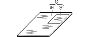
FIGS.7と8を参照すると、感温抵抗52を電流制御層50の中央部ではなく、電流制御層50の隅部に設けることも可能である。感温抵抗52を電流制御層50の隅部に設けると、感温抵抗52を電流制御層50の中央部に設ける場合と比べて積層体30の温度上昇による感温抵抗52の昇温促進作用が限定されるが、電流制御層50内に何らかの制約がある場合には、感温抵抗52のこうした配置も可能である。
Fig. Referring to FIGS. 7 and 8, the temperature-sensitive resistor 52 can be provided not at the center of the current control layer 50 but at the corner of the current control layer 50. When the temperature sensitive resistor 52 is provided at the corner of the current control layer 50, the temperature increase resistance of the temperature sensitive resistor 52 is promoted by the temperature rise of the laminate 30 as compared with the case where the temperature sensitive resistor 52 is provided at the center of the current control layer 50. However, in the case where there are some restrictions in the current control layer 50, such arrangement of the temperature-sensitive resistor 52 is also possible.
以上のように、この双極型二次電池100によれば、短絡電流などの過大電流が双極型二次電池100に流れる場合に、感温抵抗52が双極型二次電池100の温度上昇に応じて電気抵抗を増大させる。これにより、電流を遮断あるいは抑制することで、電池本体300の温度上昇を抑えることができる。
As described above, according to the bipolar secondary battery 100, when an excessive current such as a short circuit current flows through the bipolar secondary battery 100, the temperature sensitive resistor 52 responds to the temperature rise of the bipolar secondary battery 100. Increase electrical resistance. Thereby, the temperature rise of the battery main body 300 can be suppressed by interrupting or suppressing the current.
特に、感温抵抗52の電気抵抗の増大開始温度を、電解液の沸点温度あるいはセパレータの溶融温度のうちの低い方以下とすることで、電解液の沸騰やセパレータの溶融を阻止することができる。
In particular, the boiling point of the electrolytic solution and the melting of the separator can be prevented by setting the increase start temperature of the electric resistance of the temperature-sensitive resistor 52 to the lower one of the boiling point temperature of the electrolytic solution or the melting temperature of the separator. .
FIG.9を参照してこの発明の第2の実施例を説明する。この図も特徴を分かりやすく示すために、要部をデフォルメして描いている。
FIG. A second embodiment of the present invention will be described with reference to FIG. This figure also shows the main part deformed to show the features in an easy-to-understand manner.
この実施例では、電流制御層50と集電体22a及び22bとの間に、双極型電極21より抵抗の小さい電流緩和層56をそれぞれ挟持する。
In this embodiment, a current relaxation layer 56 having a resistance smaller than that of the bipolar electrode 21 is sandwiched between the current control layer 50 and the current collectors 22a and 22b.
電流緩和層56は、アルミニウム(Al)や銅(Cu)などの金属箔または金属板で構成する。双極型二次電池100の他の構成は第1の実施例と同一である。
The current relaxation layer 56 is made of a metal foil or a metal plate such as aluminum (Al) or copper (Cu). The other structure of the bipolar secondary battery 100 is the same as that of the first embodiment.
この実施例において、電流緩和層56の電気抵抗が双極型電極21より低いため、双極型電極21の抵抗が大きい場合でも、双極型電極21からの電流を電流緩和層56を通して感温抵抗52に集めることができる。すなわち、電流緩和層56が感温抵抗52への電流集中を促進するので、感温抵抗52の自己発熱を促進することができる。電流緩和層56による電流集中の促進作用は双極型電極21の抵抗が大きいほど顕著に現れる。
In this embodiment, since the electric resistance of the current relaxation layer 56 is lower than that of the bipolar electrode 21, even when the resistance of the bipolar electrode 21 is large, the current from the bipolar electrode 21 passes through the current relaxation layer 56 to the temperature sensitive resistor 52. Can be collected. That is, since the current relaxation layer 56 promotes current concentration on the temperature-sensitive resistor 52, self-heating of the temperature-sensitive resistor 52 can be promoted. The current concentration promoting action by the current relaxation layer 56 becomes more prominent as the resistance of the bipolar electrode 21 increases.
電流緩和層56は電流制御層50の両側に設けることが望ましいが、電流制御層50の片側にのみ設ける場合でも、一方の積層体30からの電流集中を促進することができる。
It is desirable to provide the current relaxation layer 56 on both sides of the current control layer 50, but even when it is provided only on one side of the current control layer 50, current concentration from one of the stacked bodies 30 can be promoted.
次にFIGS.10A-10C,FIGS.11Aと11B,FIGS.12Aと12B,FIG.13,及びFIG.14を参照して、双極型二次電池100の製造と得られた製品の電流抑制能力に関して、発明者らが行った実験について説明する。
Next, FIG. 10A-10C, FIGS. 11A and 11B, FIG. 12A and 12B, FIG. 13, and FIG. Referring to FIG. 14, an experiment conducted by the inventors regarding the manufacture of the bipolar secondary battery 100 and the current suppression capability of the obtained product will be described.
まず双極型電極21の作成プロセスを説明する。
First, the creation process of the bipolar electrode 21 will be described.
正極活物質層23を下記の要領により作成した。すなわち、正極活物質としてLiMn2O4を85重量パーセント(wt%)に、導電助剤としてアセチレンブラックを5wt%、バインダーとしてポリフッ化ビニリデン(PVdF)を10wt%、スラリー粘度調整溶媒としてNメチルピロドリン(NMP)を塗布作業に最適な粘度になるまで添加し、正極スラリーを作製した。
The positive electrode active material layer 23 was created in the following manner. That is, 85% by weight (wt%) of LiMn 2 O 4 as a positive electrode active material, 5 wt% of acetylene black as a conductive auxiliary agent, 10 wt% of polyvinylidene fluoride (PVdF) as a binder, and N-methylpyrodoline (NMP) as a slurry viscosity adjusting solvent ) Was added until the viscosity became optimum for the coating operation to prepare a positive electrode slurry.
集電体22としての厚さ20ミクロン(μm)のSUS箔の片面に正極スラリーを塗布し、乾燥させて30μmの正極活物質層23を形成した。
A positive electrode slurry was applied to one side of a SUS foil having a thickness of 20 microns (μm) as the current collector 22, and dried to form a positive electrode active material layer 23 having a thickness of 30 μm.
負極活物質層24を下記の要領により作成した。すなやち、負極活物質としてハードカーボンを90wt%、バインダーとしてPVDFを10wt%、スラリー粘度調整溶媒としてNMPを塗布作業に最適な粘度になるまで添加し、負極スラリーを作製した。
The negative electrode active material layer 24 was created in the following manner. That is, 90 wt% of hard carbon as a negative electrode active material, 10 wt% of PVDF as a binder, and NMP as a slurry viscosity adjusting solvent were added until the viscosity became optimum for the coating operation to prepare a negative electrode slurry.
集電体22の正極活物質層23と反対側の面に負極スラリーを塗布し、乾燥させて30μmの負極活物質層24を形成した。
A negative electrode slurry was applied to the surface of the current collector 22 opposite to the positive electrode active material layer 23 and dried to form a 30 μm negative electrode active material layer 24.
このように、集電体22としてのSUS箔の両面に正極活物質層23と負極活物質層24を形成することで、双極型電極21の構造体を得た。
Thus, the structure of the bipolar electrode 21 was obtained by forming the positive electrode active material layer 23 and the negative electrode active material layer 24 on both surfaces of the SUS foil as the current collector 22.
FIG.10A-10Cを参照すると、双極型電極21を160×130ミリメートル(mm)に切り取り、正極、負極ともに外周部を幅10mmずつ剥がし取ることにより、SUSの表面を露出させた。結果として、140×110mmの電極面と、その外周に露出する10mm幅のSUSが構成する集電体22とを有する双極型電極21を作製した。
FIG. Referring to 10A-10C, the bipolar electrode 21 was cut to 160 × 130 millimeters (mm), and both the positive electrode and the negative electrode were peeled off by 10 mm in width to expose the surface of SUS. As a result, a bipolar electrode 21 having a 140 × 110 mm electrode surface and a current collector 22 made of SUS having a width of 10 mm exposed on the outer periphery thereof was produced.
次に電解質層25の形成プロセスを説明する。
Next, the formation process of the electrolyte layer 25 will be described.
プロピレンカーボネート-エチレンカーボネート(PC-EC)の混合溶媒に1モルの六フッ化ホウ酸リチウム(LiPF6)を含有する沸点が242℃の電解液を90wt%、ホストポリマーとしてヘキサフルオロプロペン(HFP)コポリマーを10%含むPVdF-HFPを10wt%含むプレゲル電解質を作成した。これに、粘度調製溶媒としてジメチルカーボネート(DMC)を塗布作業に最適な粘度になるまで添加することで電解液を生成した。電解液を双極型電極21の正極活物質層23と負極活物質層24の各電極面に塗布し、DMCを乾燥させた。
90 wt% of an electrolyte solution having a boiling point of 242 ° C containing 1 mol of lithium hexafluoroborate (LiPF6) in a mixed solvent of propylene carbonate-ethylene carbonate (PC-EC), and hexafluoropropene (HFP) copolymer as a host polymer A pregel electrolyte containing 10 wt% of PVdF-HFP containing 10% was prepared. To this, dimethyl carbonate (DMC) was added as a viscosity adjusting solvent until the viscosity became optimum for the coating operation to produce an electrolytic solution. The electrolyte solution was applied to the electrode surfaces of the positive electrode active material layer 23 and the negative electrode active material layer 24 of the bipolar electrode 21, and the DMC was dried.
この双極型電極21をFIGS.12Aと12Bに示すように、セパレータSPと交互に重ね合わせることで、正極活物質層23と負極活物質層24の各電極面に塗布された電解液をセパレータSPに含浸させた。このようにして、セパレータSPの、正極活物質層23と負極活物質層24の各電極面に対応する領域範囲。に電解質層25を形成した。
This bipolar electrode 21 is shown in FIG. As shown in 12A and 12B, the separator SP was impregnated with the electrolyte solution applied to the electrode surfaces of the positive electrode active material layer 23 and the negative electrode active material layer 24 by alternately overlapping the separator SP. Thus, the area | region range corresponding to each electrode surface of the positive electrode active material layer 23 and the negative electrode active material layer 24 of separator SP. An electrolyte layer 25 was formed.
次にシール部前駆体の形成プロセスを説明する。
Next, the process for forming the seal portion precursor will be described.
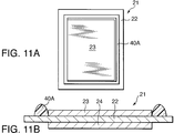
FIGS.11Aと11Bを参照すると、双極型電極21の正極外側のSUS箔の露出部にディスペンサを用いて、1液性未硬化エポキシ樹脂からなるシール前駆体40Aを塗布した。
Fig. Referring to 11A and 11B, a seal precursor 40A made of a one-component uncured epoxy resin was applied to the exposed portion of the SUS foil outside the positive electrode of the bipolar electrode 21 using a dispenser.
FIGS.12Aと12bを参照すると、次に、12μm厚で融点134℃のポリエチレン(PE)フィルムからなる170×140(mm)のセパレータSPをSUSを含む集電体22の全面を覆うように正極側に配置した。後述する用例#8のみは、15μm厚で融点350℃以上のポリイミド(PI)セパレータを使用した。その後に、セパレータSPのシール前駆体40Aと重なる位置にディスペンサを用いて、1液性未硬化エポキシ樹脂からなるシール前駆体40Aを塗布した。
Fig. Referring to 12A and 12b, a 170 × 140 (mm) separator SP made of a polyethylene (PE) film having a thickness of 12 μm and a melting point of 134 ° C. is applied to the positive electrode side so as to cover the entire surface of the current collector 22 containing SUS. Arranged. Only Example # 8 described below used a polyimide (PI) separator having a thickness of 15 μm and a melting point of 350 ° C. or higher. Thereafter, a seal precursor 40A made of a one-part uncured epoxy resin was applied using a dispenser at a position overlapping the seal precursor 40A of the separator SP.
ここで、セパレータSPは、図に示すように、全周においてシール部前駆体40Aを突き抜けてシール部前駆体40Aの外側に突出している。この突出部位は正極活物質層23とも負極活物質層24とも接触せず、この部位に電解質層25は形成されない。電解質層25が形成されるのは、シール前駆体40Aに囲まれた領域のみである。
Here, as shown in the figure, the separator SP penetrates the seal portion precursor 40A and protrudes outside the seal portion precursor 40A on the entire circumference. The protruding portion does not contact the positive electrode active material layer 23 and the negative electrode active material layer 24, and the electrolyte layer 25 is not formed at this portion. The electrolyte layer 25 is formed only in the region surrounded by the seal precursor 40A.
以上の双極型電極21とセパレータSPとを13組積層することで、セル26が12個積層された積層体30の構造体を作製した。
By stacking 13 sets of the above bipolar electrode 21 and separator SP, a structure of a stacked body 30 in which 12 cells 26 were stacked was manufactured.
次に双極型電池のプレス形成について説明する。
Next, the press forming of the bipolar battery will be described.
FIG.13を参照すると、以上のように構成された積層体30の構造体を、間に電流制御層50を挟んで、熱プレス機により面圧1キログラム(kg)/平方センチメートル(cm2)(≒キロパスカル(kPa))で80℃で1時間熱プレスすることにより、シール前駆体40Aを硬化させて、シール部40を得た。このプロセスにより、シール部40を所定の厚みまでプレスでき、さらに硬化させることが可能になる。以上のプロセスでセル26を12層積層した積層体30を完成させた。
FIG. 13, the structure of the laminated body 30 configured as described above is subjected to a surface pressure of 1 kilogram (kg) / square centimeter (cm2) (≈ kilopascals) by a heat press with the current control layer 50 interposed therebetween. (KPa)) was subjected to hot pressing at 80 ° C. for 1 hour to cure the seal precursor 40A and obtain the seal portion 40. By this process, the seal portion 40 can be pressed to a predetermined thickness and can be further cured. The laminated body 30 in which 12 layers of the cells 26 were laminated by the above process was completed.
次に電流制御層50の作成プロセスを説明する。
Next, a process for creating the current control layer 50 will be described.
厚さ300μmのPET板をセパレータSPと同様の寸法170mm×140mmに切り出した。切り出したPET板のFIG.4に示す中央部に相当する位置に感温抵抗52が嵌合する大きさの切り抜きを設けた。後述の用例#13用のPET板のみは、FIG.7に示すように電流制御層50の遇部に相当する位置に感温抵抗52が嵌合する大きさの切り抜きを設けた。
A PET plate having a thickness of 300 μm was cut into a size of 170 mm × 140 mm similar to the separator SP. FIG. A cutout with a size that allows the temperature-sensitive resistor 52 to fit is provided at a position corresponding to the central portion shown in FIG. Only the PET plate for Example # 13 to be described later is shown in FIG. As shown in FIG. 7, a cutout having a size for fitting the temperature-sensitive resistor 52 is provided at a position corresponding to the treatment portion of the current control layer 50.
感温抵抗52には抵抗が急激に増大し始める温度が140℃、120℃、110℃である、異なるポリマーPTCシートを、所定の面積に切り抜いて使用した。
As the temperature-sensitive resistor 52, different polymer PTC sheets having temperatures of 140 ° C., 120 ° C., and 110 ° C. at which the resistance starts to increase sharply were cut into a predetermined area and used.
後述する用例#10に用いる電流緩和層56は、50μmのアルミニウム(Al)板を160×130(mm)に切り出すことで作成した。作成した2枚の電流緩和層56を、電流制御層50を両側から挟み込むように配置した。
The current relaxation layer 56 used in Example # 10 to be described later was created by cutting a 50 μm aluminum (Al) plate into 160 × 130 (mm). The two current relaxation layers 56 thus prepared were arranged so as to sandwich the current control layer 50 from both sides.
次にパッケージングについて説明する。
Next, packaging will be described.
上記プロセスで作成した2個または4個の積層体30のうちいずれか2個の積層体30の間に導電性両面テープを介して電流制御層50を挟持することで電池本体300を得た。用例10に関しては、電流制御層50の両面に導電性両面テープを介して2枚の電流緩和層56を固定し、これを2個の積層体30の間に導電性両面テープを介して挟持することで、用例#1-#13の電池本体300を得た。
The battery body 300 was obtained by sandwiching the current control layer 50 between any two of the two or four laminates 30 created by the above process via a conductive double-sided tape. Regarding Example 10, two current relaxation layers 56 are fixed to both surfaces of the current control layer 50 via a conductive double-sided tape, and are sandwiched between the two laminates 30 via a conductive double-sided tape. As a result, the battery body 300 of Examples # 1- # 13 was obtained.
一方、比較例#1については2個の積層体30を導電性両面テープで直接接着して電池本体300を得た。
On the other hand, for Comparative Example # 1, two laminated bodies 30 were directly bonded with a conductive double-sided tape to obtain a battery body 300.
さらに、電池本体300の両端に正極集電板101と負極集電板102とを導電性両面テープにより接着した。正極集電板101の電池本体300と反対側の面をケース部材103aの内周面に両面テープで接着した。正極集電板101と負極集電板102の取り出し部をケース部材103aと103bのフランジ部が挟む形で、ケース103が真空密封されるようにフランジ部を溶着した。
Further, the positive electrode current collector plate 101 and the negative electrode current collector plate 102 were bonded to both ends of the battery main body 300 with a conductive double-sided tape. The surface of the positive electrode current collector plate 101 opposite to the battery main body 300 was bonded to the inner peripheral surface of the case member 103a with a double-sided tape. The flange portions were welded so that the case 103 was vacuum-sealed in such a manner that the flange portions of the case members 103a and 103b sandwich the take-out portion of the positive electrode current collector plate 101 and the negative electrode current collector plate 102.
以上のプロセスにより、双極型二次電池100に関するこの発明による用例#1-#13とこの発明によらない比較例#1を完成させた。
By the above process, Example # 1- # 13 according to the present invention relating to the bipolar secondary battery 100 and Comparative Example # 1 not according to the present invention were completed.
用例#1-#13と比較例#1の仕様をTABLE-1に示す。
The specifications of Example # 1- # 13 and Comparative Example # 1 are shown in TABLE-1.
FIG.14を参照すると、この発明によらない比較例#1では、2個の積層体30を感温抵抗52を挟持することなく、直接接触させた。
FIG. Referring to FIG. 14, in Comparative Example # 1 not according to the present invention, the two laminated bodies 30 were brought into direct contact without sandwiching the temperature-sensitive resistor 52.
用例#1-#10では、電池本体300を2個の積層体30で構成し、2個の積層体30の間に電流制御層50を配置し、電流制御層50の中央部に感温抵抗52を配置した。
In Examples # 1 to # 10, the battery body 300 is composed of two stacked bodies 30, the current control layer 50 is disposed between the two stacked bodies 30, and the temperature sensitive resistor is located at the center of the current control layer 50. 52 was placed.
用例#1では、抵抗増大開始温度140℃の感温抵抗52の面積を正極活物質層23と負極活物質層24との電気反応エリアの2/3に設定した。
In Example # 1, the area of the temperature-sensitive resistor 52 having a resistance increase start temperature of 140 ° C. was set to 2/3 of the electric reaction area between the positive electrode active material layer 23 and the negative electrode active material layer 24.
用例#2では、抵抗増大開始温度140℃の感温抵抗52の面積を正極活物質層23と負極活物質層24との電気反応エリアの1/2に設定した。
In Example # 2, the area of the temperature-sensitive resistor 52 having a resistance increase start temperature of 140 ° C. was set to ½ of the electric reaction area between the positive electrode active material layer 23 and the negative electrode active material layer 24.
用例#3では、抵抗増大開始温度140℃の感温抵抗52の面積を正極活物質層23と負極活物質層24との電気反応エリアの1/5に設定した。
In Example # 3, the area of the temperature-sensitive resistor 52 having a resistance increase start temperature of 140 ° C. was set to 1/5 of the electric reaction area between the positive electrode active material layer 23 and the negative electrode active material layer 24.
用例#4では、抵抗増大開始温度140℃の感温抵抗52の面積を正極活物質層23と負極活物質層24との電気反応エリアの1/50に設定した。
In Example # 4, the area of the temperature-sensitive resistor 52 having a resistance increase start temperature of 140 ° C. was set to 1/50 of the electric reaction area between the positive electrode active material layer 23 and the negative electrode active material layer 24.
用例#5では、抵抗増大開始温度140℃の感温抵抗52の面積を正極活物質層23と負極活物質層24との電気反応エリアの1/100に設定した。
In Example # 5, the area of the temperature-sensitive resistor 52 having a resistance increase start temperature of 140 ° C. was set to 1/100 of the electric reaction area between the positive electrode active material layer 23 and the negative electrode active material layer 24.
用例#6では、抵抗増大開始温度140℃の感温抵抗52の面積を正極活物質層23と負極活物質層24との電気反応エリアの1/500に設定した。この場合の双極型二次電池100の通常使用時における感温抵抗52の抵抗値は、積層体30の内部抵抗の3/100程度であった。
In Example # 6, the area of the temperature-sensitive resistor 52 having a resistance increase start temperature of 140 ° C. was set to 1/500 of the electric reaction area between the positive electrode active material layer 23 and the negative electrode active material layer 24. In this case, the resistance value of the temperature-sensitive resistor 52 during normal use of the bipolar secondary battery 100 was about 3/100 of the internal resistance of the multilayer body 30.
用例#7では、抵抗増大開始温度120℃の感温抵抗52の面積を正極活物質層23と負極活物質層24との電気反応エリアの1/100に設定した。
In Example # 7, the area of the temperature-sensitive resistor 52 having a resistance increase start temperature of 120 ° C. was set to 1/100 of the electric reaction area between the positive electrode active material layer 23 and the negative electrode active material layer 24.
用例#8では、用例#5と同様に、抵抗増大開始温度140℃の感温抵抗52の面積を積層体30の正極活物質層23と負極活物質層24との電気反応エリアの1/100に設定した。また、セパレータSPに前述のように、15μm厚で融点が350℃以上のポリイミド(PI)セパレータを使用した。他の用例及び比較例#1のセパレータSPは融点が134℃のポリエチレン(PE)製である。
In Example # 8, similarly to Example # 5, the area of the temperature-sensitive resistor 52 having a resistance increase start temperature of 140 ° C. is 1/100 of the electric reaction area between the positive electrode active material layer 23 and the negative electrode active material layer 24 of the laminate 30. Set to. Further, as described above, a polyimide (PI) separator having a thickness of 15 μm and a melting point of 350 ° C. or higher was used as the separator SP. The separator SP of other examples and comparative example # 1 is made of polyethylene (PE) having a melting point of 134 ° C.
用例#9では、抵抗増大開始温度110℃の感温抵抗52を使用し、感温抵抗52の面積を正極活物質層23と負極活物質層24との電気反応エリアの1/100に設定した。
In Example # 9, a temperature-sensitive resistor 52 having a resistance increase start temperature of 110 ° C. was used, and the area of the temperature-sensitive resistor 52 was set to 1/100 of the electric reaction area between the positive electrode active material layer 23 and the negative electrode active material layer 24. .
用例#10では、前述のプロセスで作成した電流緩和層56を、FIG.9に示すように、電流制御層50と両側の積層体30との間に配置した。
In Example # 10, the current relaxation layer 56 created by the above-described process is replaced with FIG. As shown in FIG. 9, the current control layer 50 and the laminated body 30 on both sides were disposed.
用例#11-#13では、電池本体300を4個の積層体30で構成した。
In usage examples # 11 to # 13, the battery body 300 is composed of the four laminated bodies 30.
用例#11では、抵抗増大開始温度120℃の感温抵抗52の面積を正極活物質層23と負極活物質層24との電気反応エリアの1/100に設定した。また、FIG.5に示すように、電流制御層50を電池本体300の一端から数えて2個目と3個目の積層体30の間、すなわち積層体30の積層方向に関する電池本体300の中間部に配置した。
In Example # 11, the area of the temperature-sensitive resistor 52 having a resistance increase start temperature of 120 ° C. was set to 1/100 of the electric reaction area between the positive electrode active material layer 23 and the negative electrode active material layer 24. In addition, FIG. As shown in FIG. 5, the current control layer 50 is arranged between the second and third stacked bodies 30 counted from one end of the battery body 300, that is, in the middle portion of the battery body 300 in the stacking direction of the stacked body 30. .
用例#12では、抵抗増大開始温度120℃の感温抵抗52を使用し、感温抵抗52の面積を正極活物質層23と負極活物質層24との電気反応エリアの1/100に設定した。また、FIG.6に示すように、電流制御層50を積層体30の積層方向に関する電池本体300の一端から数えて1個目と2個目の積層体30の間、すなわち電池本体300の中間部から離れた位置に配置した。
In Example # 12, a temperature-sensitive resistor 52 having a resistance increase start temperature of 120 ° C. was used, and the area of the temperature-sensitive resistor 52 was set to 1/100 of the electric reaction area between the positive electrode active material layer 23 and the negative electrode active material layer 24. . In addition, FIG. 6, the current control layer 50 is counted from one end of the battery body 300 in the stacking direction of the stacked body 30, and is separated from the first and second stacked bodies 30, that is, away from the middle portion of the battery body 300. Placed in position.
用例#13では、抵抗増大開始温度120℃の感温抵抗52を使用し、感温抵抗52の面積を正極活物質層23と負極活物質層24との電気反応エリアの1/100に設定した。また、電流制御層50を積層体30の積層方向に関する電池本体300の一端から数えて2個目と3個目の積層体30の間、すなわち電池本体300の中間部に配置した。一方、FIGS.7と8に示すように、感温抵抗52を電流制御層50の隅部に配置した。
In Example # 13, a temperature-sensitive resistor 52 having a resistance increase start temperature of 120 ° C. was used, and the area of the temperature-sensitive resistor 52 was set to 1/100 of the electric reaction area between the positive electrode active material layer 23 and the negative electrode active material layer 24. . Further, the current control layer 50 is disposed between the second and third stacked bodies 30 counted from one end of the battery body 300 in the stacking direction of the stacked body 30, that is, in the middle portion of the battery body 300. On the other hand, FIG. As shown in FIGS. 7 and 8, the temperature-sensitive resistor 52 is disposed at the corner of the current control layer 50.
なお、比較例#1と用例#1-#13のすべてにおいて、電解液の沸点は140℃とする。
In all of Comparative Example # 1 and Examples # 1- # 13, the boiling point of the electrolyte is 140 ° C.
比較例#1及び用例#1-#13の双極型二次電池100に接続された外部電気回路の短絡試験を実施して、電池本体300の到達最大温度と最大温度到達時間を測定し、試験後の電池状態を確認した。試験結果をTABLE-2AとTABLE-2Bに示す。
A short circuit test of the external electric circuit connected to the bipolar secondary battery 100 of Comparative Example # 1 and Use Example # 1- # 13 is performed, and the maximum temperature and the maximum temperature arrival time of the battery body 300 are measured, and the test The later battery state was confirmed. The test results are shown in TABLE-2A and TABLE-2B.
TABLE-2AとTABLE-2Bを参照すると、比較例#1では、電流制御層50が存在しないため、30秒程度で電解液の沸点に到達し、沸騰した電解液で電池本体300に大きな膨れが発生した。一方、電流制御層50を有する用例#1-#13では、すべての電池で電流の抑制が見られ、到達最大温度が低くなるとともに、最大温度への到達時間を遅らせることができた。
Referring to TABLE-2A and TABLE-2B, in Comparative Example # 1, since the current control layer 50 does not exist, the boiling point of the electrolytic solution is reached in about 30 seconds, and the battery body 300 is greatly swollen by the boiling electrolytic solution. Occurred. On the other hand, in Examples # 1- # 13 having the current control layer 50, current suppression was observed in all the batteries, the maximum temperature reached was lowered, and the time required to reach the maximum temperature could be delayed.
また、用例#1-#6を比較すると、感温抵抗52の面積を小さくしていくと、電池本体300の到達最大温度が低下するとともに、最大温度到達時間が長くなることがわかる。特に正極活物質層23と負極活物質層24との電気反応エリアに対する感温抵抗52の面積比を1/2以下にすると、電池本体300の到達最大温度がさらに低下し、最大温度到達時間が大幅に長くなる。
Further, comparing Examples # 1- # 6, it can be seen that, as the area of the temperature-sensitive resistor 52 is reduced, the maximum temperature reached by the battery main body 300 decreases and the maximum temperature arrival time increases. In particular, when the area ratio of the temperature-sensitive resistor 52 to the electric reaction area between the positive electrode active material layer 23 and the negative electrode active material layer 24 is ½ or less, the maximum temperature reached by the battery body 300 is further reduced, and the maximum temperature arrival time is reduced. Significantly longer.
ただし、用例#6のように、感温抵抗52の面積比を小さくしすぎると、積層体30の内部抵抗に占める電流制御層50の抵抗が3/100と大きくなり、通常動作における積層体30の出力に影響を与えてしまう。このため、電流制御層50が占める抵抗は積層体30の内部抵抗に対して1/100以上とするのが好ましい。
However, if the area ratio of the temperature-sensitive resistor 52 is too small as in Example # 6, the resistance of the current control layer 50 occupying the internal resistance of the multilayer body 30 becomes 3/100, and the multilayer body 30 in normal operation. Affects the output of. Therefore, the resistance occupied by the current control layer 50 is preferably 1/100 or more with respect to the internal resistance of the multilayer body 30.
用例#1-#6では、感温抵抗52の抵抗増大開始温度がいずれも140℃であり、これは電解液の沸点140℃に等しく、かつセパレータSPの融点134℃を上回っている。このため、電流抑制効果は得られるものの、最大到達温度は215℃-250℃と、いずれも、セパレータSPの融点や電解液の沸点を上回る。このためセパレータSPの溶融や、電解液の沸騰を完全阻止することはできない。結果として、電池本体300に何らかの膨張変形が生じる。
In Examples # 1 to # 6, the temperature increase start temperature of each of the temperature sensitive resistors 52 is 140 ° C., which is equal to the boiling point 140 ° C. of the electrolyte and exceeds the melting point 134 ° C. of the separator SP. Therefore, although the current suppressing effect can be obtained, the maximum temperature reached is 215 ° C.-250 ° C., both exceeding the melting point of the separator SP and the boiling point of the electrolyte. For this reason, the melting of the separator SP and the boiling of the electrolytic solution cannot be completely prevented. As a result, some expansion deformation occurs in the battery body 300.
一方、用例#7では、感温抵抗52の抵抗増大開始温度120℃は、電解液の沸点140℃とセパレータSPの融点134℃の低い方の温度以下という条件を満たしている。同様に、用例#8も、感温抵抗52の抵抗増大開始温度140℃は、電解液の沸点140℃とセパレータSPの融点350℃の低い方の温度以下という条件を満たしている。用例#7と#8では、到達最大温度が電解液の沸点140℃以下に抑えられ、電池本体300の変形を防止することができた。
On the other hand, in Example # 7, the resistance increase start temperature 120 ° C. of the temperature-sensitive resistor 52 satisfies the condition that the lower temperature of the boiling point 140 ° C. of the electrolyte and the melting point 134 ° C. of the separator SP is equal to or lower. Similarly, Example # 8 also satisfies the condition that the resistance increase start temperature 140 ° C. of the temperature-sensitive resistor 52 is equal to or lower than the lower one of the boiling point 140 ° C. of the electrolytic solution and the melting point 350 ° C. of the separator SP. In Examples # 7 and # 8, the maximum temperature reached was suppressed to 140 ° C. or lower, which was the boiling point of the electrolytic solution, and deformation of the battery body 300 could be prevented.
用例#9では、感温抵抗52の抵抗増大開始温度がさらに低いので、到達最大温度は電解液の沸点140℃とセパレータSPの融点120℃のいずれよりも低い115℃に留まり、電解液の沸騰やセパレータSPの溶融をより確実に防止できた。
In Example # 9, since the temperature increase start temperature of the temperature-sensitive resistor 52 is further lower, the maximum temperature reached is 115 ° C., which is lower than both the boiling point 140 ° C. of the electrolytic solution and the melting point 120 ° C. of the separator SP. And the melting of the separator SP could be prevented more reliably.
用例#10では、用例#7の構成に加えて、電流緩和層56を電流制御層50の両側に配置したので、感温抵抗52への電流集中度が高まり、用例#7より到達最大温度を下げ、最大温度到達時間を遅らせることができた。電流緩和層56は、集電体22と正極活物質層23と負極活物質層24からなる双極型電極21の抵抗が大きいほど効果が大きいと考えられる。
In the example # 10, in addition to the configuration of the example # 7, the current relaxation layer 56 is disposed on both sides of the current control layer 50. Therefore, the current concentration on the temperature-sensitive resistor 52 is increased, and the maximum temperature reached is higher than in the example # 7. We were able to lower the maximum temperature reaching time. The current relaxation layer 56 is considered to be more effective as the resistance of the bipolar electrode 21 including the current collector 22, the positive electrode active material layer 23, and the negative electrode active material layer 24 increases.
用例#11と用例#12の比較からは、積層体30の積層方向に関して電池本体300の中間点近くに電流制御層50を配置する場合には、他の位置に配置する場合より、最大温度への到達時間を遅らせられることが分かった。電池本体300の中間点に近い位置では、中間点から離れた位置より電池本体300の発熱の電流制御層50への伝達が早いため、と考えられる
From the comparison between the example # 11 and the example # 12, when the current control layer 50 is disposed near the middle point of the battery body 300 in the stacking direction of the stacked body 30, the maximum temperature is reached as compared with the case where the current control layer 50 is disposed at another position. It has been found that the arrival time of can be delayed. This is probably because the heat transfer from the battery main body 300 to the current control layer 50 is faster at the position close to the middle point of the battery body 300 than at the position away from the middle point.
用例#11と用例#13の比較からは、感温抵抗52が電流制御層50の中央部に配置されている場合には、隅部に配置されている場合より、最大温度への到達時間を遅らせられることが分かった。電流制御層50の中央部では隅部よりも電池本体300の発熱の電流制御層50への伝達が早いため、と考えられる
From the comparison between the example # 11 and the example # 13, when the temperature-sensitive resistor 52 is arranged at the center of the current control layer 50, the time to reach the maximum temperature is longer than when it is arranged at the corner. I found it delayed. It is considered that the heat transfer from the battery main body 300 to the current control layer 50 is faster at the center of the current control layer 50 than at the corners.
以上の説明に関して2010年5月19日を出願日とする日本国における特願2010-115123号、の内容をここに引用により合体する。
Regarding the above description, the contents of Japanese Patent Application No. 2010-115123 in Japan, whose filing date is May 19, 2010, are incorporated herein by reference.
以上、この発明をいくつかの特定の実施例を通じて説明してきたが、この発明は上記の各実施例に限定されるものではない。当業者にとっては、クレームの技術範囲でこれらの実施例にさまざまな修正あるいは変更を加えることが可能である。
Although the present invention has been described through several specific embodiments, the present invention is not limited to the above embodiments. Those skilled in the art can make various modifications or changes to these embodiments within the scope of the claims.
例えば、この発明はリチウムイオン電池に限らず、いかなる双極型二次電池にも適用可能である。
For example, the present invention is not limited to a lithium ion battery but can be applied to any bipolar secondary battery.