WO2011145488A1 - 電動アクチュエータの制御装置 - Google Patents
電動アクチュエータの制御装置 Download PDFInfo
- Publication number
- WO2011145488A1 WO2011145488A1 PCT/JP2011/060808 JP2011060808W WO2011145488A1 WO 2011145488 A1 WO2011145488 A1 WO 2011145488A1 JP 2011060808 W JP2011060808 W JP 2011060808W WO 2011145488 A1 WO2011145488 A1 WO 2011145488A1
- Authority
- WO
- WIPO (PCT)
- Prior art keywords
- pressure
- pilot
- electric actuator
- control device
- reverse
- Prior art date
- Legal status (The legal status is an assumption and is not a legal conclusion. Google has not performed a legal analysis and makes no representation as to the accuracy of the status listed.)
- Ceased
Links
Images



Classifications
-
- E—FIXED CONSTRUCTIONS
- E02—HYDRAULIC ENGINEERING; FOUNDATIONS; SOIL SHIFTING
- E02F—DREDGING; SOIL-SHIFTING
- E02F9/00—Component parts of dredgers or soil-shifting machines, not restricted to one of the kinds covered by groups E02F3/00 - E02F7/00
- E02F9/08—Superstructures; Supports for superstructures
- E02F9/10—Supports for movable superstructures mounted on travelling or walking gears or on other superstructures
- E02F9/12—Slewing or traversing gears
- E02F9/121—Turntables, i.e. structure rotatable about 360°
- E02F9/123—Drives or control devices specially adapted therefor
-
- E—FIXED CONSTRUCTIONS
- E02—HYDRAULIC ENGINEERING; FOUNDATIONS; SOIL SHIFTING
- E02F—DREDGING; SOIL-SHIFTING
- E02F3/00—Dredgers; Soil-shifting machines
- E02F3/04—Dredgers; Soil-shifting machines mechanically-driven
- E02F3/28—Dredgers; Soil-shifting machines mechanically-driven with digging tools mounted on a dipper- or bucket-arm, i.e. there is either one arm or a pair of arms, e.g. dippers, buckets
- E02F3/36—Component parts
- E02F3/42—Drives for dippers, buckets, dipper-arms or bucket-arms
- E02F3/43—Control of dipper or bucket position; Control of sequence of drive operations
-
- E—FIXED CONSTRUCTIONS
- E02—HYDRAULIC ENGINEERING; FOUNDATIONS; SOIL SHIFTING
- E02F—DREDGING; SOIL-SHIFTING
- E02F9/00—Component parts of dredgers or soil-shifting machines, not restricted to one of the kinds covered by groups E02F3/00 - E02F7/00
- E02F9/20—Drives; Control devices
- E02F9/2058—Electric or electro-mechanical or mechanical control devices of vehicle sub-units
- E02F9/2095—Control of electric, electro-mechanical or mechanical equipment not otherwise provided for, e.g. ventilators, electro-driven fans
-
- E—FIXED CONSTRUCTIONS
- E02—HYDRAULIC ENGINEERING; FOUNDATIONS; SOIL SHIFTING
- E02F—DREDGING; SOIL-SHIFTING
- E02F9/00—Component parts of dredgers or soil-shifting machines, not restricted to one of the kinds covered by groups E02F3/00 - E02F7/00
- E02F9/20—Drives; Control devices
- E02F9/22—Hydraulic or pneumatic drives
-
- E—FIXED CONSTRUCTIONS
- E02—HYDRAULIC ENGINEERING; FOUNDATIONS; SOIL SHIFTING
- E02F—DREDGING; SOIL-SHIFTING
- E02F9/00—Component parts of dredgers or soil-shifting machines, not restricted to one of the kinds covered by groups E02F3/00 - E02F7/00
- E02F9/20—Drives; Control devices
- E02F9/22—Hydraulic or pneumatic drives
- E02F9/2221—Control of flow rate; Load sensing arrangements
-
- F—MECHANICAL ENGINEERING; LIGHTING; HEATING; WEAPONS; BLASTING
- F15—FLUID-PRESSURE ACTUATORS; HYDRAULICS OR PNEUMATICS IN GENERAL
- F15B—SYSTEMS ACTING BY MEANS OF FLUIDS IN GENERAL; FLUID-PRESSURE ACTUATORS, e.g. SERVOMOTORS; DETAILS OF FLUID-PRESSURE SYSTEMS, NOT OTHERWISE PROVIDED FOR
- F15B2211/00—Circuits for servomotor systems
- F15B2211/20—Fluid pressure source, e.g. accumulator or variable axial piston pump
- F15B2211/205—Systems with pumps
- F15B2211/2053—Type of pump
- F15B2211/20546—Type of pump variable capacity
- F15B2211/20553—Type of pump variable capacity with pilot circuit, e.g. for controlling a swash plate
-
- F—MECHANICAL ENGINEERING; LIGHTING; HEATING; WEAPONS; BLASTING
- F15—FLUID-PRESSURE ACTUATORS; HYDRAULICS OR PNEUMATICS IN GENERAL
- F15B—SYSTEMS ACTING BY MEANS OF FLUIDS IN GENERAL; FLUID-PRESSURE ACTUATORS, e.g. SERVOMOTORS; DETAILS OF FLUID-PRESSURE SYSTEMS, NOT OTHERWISE PROVIDED FOR
- F15B2211/00—Circuits for servomotor systems
- F15B2211/20—Fluid pressure source, e.g. accumulator or variable axial piston pump
- F15B2211/275—Control of the prime mover, e.g. hydraulic control
-
- F—MECHANICAL ENGINEERING; LIGHTING; HEATING; WEAPONS; BLASTING
- F15—FLUID-PRESSURE ACTUATORS; HYDRAULICS OR PNEUMATICS IN GENERAL
- F15B—SYSTEMS ACTING BY MEANS OF FLUIDS IN GENERAL; FLUID-PRESSURE ACTUATORS, e.g. SERVOMOTORS; DETAILS OF FLUID-PRESSURE SYSTEMS, NOT OTHERWISE PROVIDED FOR
- F15B2211/00—Circuits for servomotor systems
- F15B2211/50—Pressure control
- F15B2211/505—Pressure control characterised by the type of pressure control means
- F15B2211/50509—Pressure control characterised by the type of pressure control means the pressure control means controlling a pressure upstream of the pressure control means
- F15B2211/50518—Pressure control characterised by the type of pressure control means the pressure control means controlling a pressure upstream of the pressure control means using pressure relief valves
- F15B2211/50527—Pressure control characterised by the type of pressure control means the pressure control means controlling a pressure upstream of the pressure control means using pressure relief valves using cross-pressure relief valves
-
- F—MECHANICAL ENGINEERING; LIGHTING; HEATING; WEAPONS; BLASTING
- F15—FLUID-PRESSURE ACTUATORS; HYDRAULICS OR PNEUMATICS IN GENERAL
- F15B—SYSTEMS ACTING BY MEANS OF FLUIDS IN GENERAL; FLUID-PRESSURE ACTUATORS, e.g. SERVOMOTORS; DETAILS OF FLUID-PRESSURE SYSTEMS, NOT OTHERWISE PROVIDED FOR
- F15B2211/00—Circuits for servomotor systems
- F15B2211/60—Circuit components or control therefor
- F15B2211/63—Electronic controllers
- F15B2211/6303—Electronic controllers using input signals
- F15B2211/6306—Electronic controllers using input signals representing a pressure
- F15B2211/6316—Electronic controllers using input signals representing a pressure the pressure being a pilot pressure
-
- F—MECHANICAL ENGINEERING; LIGHTING; HEATING; WEAPONS; BLASTING
- F15—FLUID-PRESSURE ACTUATORS; HYDRAULICS OR PNEUMATICS IN GENERAL
- F15B—SYSTEMS ACTING BY MEANS OF FLUIDS IN GENERAL; FLUID-PRESSURE ACTUATORS, e.g. SERVOMOTORS; DETAILS OF FLUID-PRESSURE SYSTEMS, NOT OTHERWISE PROVIDED FOR
- F15B2211/00—Circuits for servomotor systems
- F15B2211/70—Output members, e.g. hydraulic motors or cylinders or control therefor
- F15B2211/705—Output members, e.g. hydraulic motors or cylinders or control therefor characterised by the type of output members or actuators
- F15B2211/7058—Rotary output members
Definitions
- the present invention relates to a control device for an electric actuator.
- An electric swivel excavator has been proposed in which a drive command is generated based on a torque current command for operation and the operability is made closer to a hydraulically driven excavator (see, for example, Patent Document 1).
- a technique has been proposed in which the control command generated for the operation lever operation of the electric swing excavator is made redundant so that the motion control of the swing body can be appropriately performed. (For example, refer to Patent Document 2).
- An object of the present invention is to provide a control device for an electric actuator capable of realizing the same operational feeling as that of a conventional hydraulically driven working machine in a hybrid type working machine in which part of the operation is performed by an electric actuator. There is a place to do.
- the control device for the electric actuator according to the first invention is: A control device for an electric actuator that controls an electric actuator capable of forward / reverse inversion operation, An operation means operable in the forward direction or the reverse direction according to the forward / reverse inversion operation of the electric actuator; A pilot circuit that is connected to the operation means and generates a forward pilot pressure or a reverse pilot pressure according to a forward operation or a reverse operation of the operation means; A differential pressure acquisition means for acquiring a pilot pressure according to an operation direction of the operation means, and a differential pressure of a pilot pressure in a direction opposite to the operation direction; Control command generation means for generating a control command to the electric actuator based on the differential pressure generated by the differential pressure acquisition means; Drive control means for performing drive control of the electric actuator based on the control command generated by the control command generation means.
- the differential pressure acquisition means A positive pressure detector for detecting a positive pilot pressure of the pilot circuit; A reverse pressure detector for detecting a reverse pilot pressure of the pilot circuit; And a differential pressure calculation unit that calculates a differential pressure between the forward pilot pressure detected by the positive pressure detection unit and the reverse pilot pressure detected by the reverse pressure unit.
- the control command is generated from the difference between the pilot pressure in the forward direction and the pilot pressure in the reverse direction by including the differential pressure acquisition unit and the control command generation unit, Drive control of the electric actuator is performed. Accordingly, the electric actuator can be driven while taking into account the influence of the back pressure generated in the direction opposite to the operation direction of the operation means, and the same operational feeling as that of the conventional hydraulic drive can be realized.
- the differential pressure acquisition means includes the forward pressure detection unit and the reverse pressure detection unit, so that the forward pilot pressure corresponding to the operation direction of the operation means, The reverse pilot pressure is detected, and the differential pressure can be easily calculated by the differential pressure calculation unit. Therefore, it can be easily incorporated into a control device such as an inverter for controlling the electric actuator.
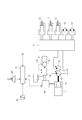
- the side view which shows the hybrid type construction machine which concerns on embodiment of this invention The schematic diagram which shows the whole structure of the hybrid type construction machine which concerns on the said embodiment.
- the block diagram which shows the control structure of the turning control apparatus which concerns on the said embodiment.
- the flowchart which shows the effect
- the graph which gives the relationship between the differential pressure
- a hybrid electric swing excavator 1 according to an embodiment of the present invention is installed on a track frame constituting a lower traveling body 2 via a swing circle 3.
- the swivel body 4 is provided, and the swivel body 4 is swiveled by an electric motor described later that meshes with the swing circle 3.
- the revolving body 4 is provided with a boom 6 driven by a boom cylinder 5, an arm 8 driven by an arm cylinder 7 is provided at the tip of the boom 6, and driven by a bucket cylinder 9 at the tip of the arm 8.
- a bucket 10 is provided.
- the revolving unit 4 is driven by an electric motor, but the present invention is not limited to this. That is, it may be a hybrid type or electric drive type electric swing excavator that drives any one of the boom 6, arm 8, bucket 10, and lower traveling body 2 of the electric swing excavator 1 with an electric motor. Further, if at least one of the drive systems is an excavator using an electric motor, the excavator is not necessarily a swivel driven by the electric motor.
- FIG. 2 shows the overall configuration of the drive system of the electric swing excavator 1.
- the electric swing excavator 1 includes an engine 11, a hydraulic pump 12, and a power generation motor 13 as drive sources.
- the engine 11 drives the hydraulic pump 12 and the generator motor 13.
- the hydraulic drive system includes a hydraulic control valve 14, the boom cylinder 5, the arm cylinder 7, the bucket cylinder 9, and the traveling motor 15 described above, and the hydraulic pump 12 is driven as a hydraulic source.
- the electric drive system includes an inverter 16, a capacitor 17, a turning control device 18, and a turning electric motor 19, and the power generation motor 13, the inverter 16, and the capacitor 17 serve as a power source for the turning electric motor 19.
- the hydraulic drive system can be driven by the operator operating the operation lever 20.
- the hydraulic drive system is provided with a pump controller.
- the pump controller generates a control command based on the operation of the operation lever 20 and controls the angle of the pump swash plate angle of the hydraulic pump 12. Do.
- the electric drive system is provided with the turning control device 18 and the target speed setting device 21 described above.
- the target speed setting device 21 is based on the setting state of the fuel dial 22, the setting state of the mode changeover switch 23, and the tilt angle of the operation lever 20 (usually also serving as a work machine lever for operating the arm 8). Is set and output to the turning control device 18.
- the fuel dial 22 is a dial for controlling the amount of fuel supplied (injected) to the engine 11, and the mode switch 23 is a switch for switching various work modes. Operated by the operator.
- a rotational speed sensor 24 is installed in the above-described turning electric motor 19. The rotation speed sensor 24 detects the rotation speed of the turning electric motor 19, and the rotation speed is fed back to the turning control device 18.
- the turning control device 18 sets a speed gain K that is a control gain based on the target speed of the turning body 4 set by the target speed setting device 21 and the rotational speed of the turning electric motor 19 detected by the rotational speed sensor 24.
- Speed control is performed by the P control (proportional control) used, and a control command for the swing electric motor 19 is generated.
- the turning control device 18 is an inverter, converts a control command into a current value and a voltage value, and outputs them to the turning electric motor 19 to control the torque output of the turning electric motor 19.
- the turning control device 18 may be other than an inverter as long as it can issue a command to drive the turning electric motor 19 by switching or the like, for example.
- a pilot circuit 25 is connected to the operation lever 20 (operation means of the present invention) in this embodiment, and this pilot circuit is used in the electric drive system.
- the operation of the operation lever 20 is transmitted to the turning control device 18 through 25.
- the pilot circuit 25 includes a left pilot valve 26, a right pilot valve 27, a pipeline 28, a throttle 29A, a check valve 29B, a tank 30, a left pressure sensor 31, and a right pressure sensor 32 using the hydraulic pump 12 as a hydraulic source.
- the voltage signals detected by the left pressure sensor 31 and the right pressure sensor 32 are input to the turning control device 18.
- the above-described hydraulic pump 12 is provided with a pilot pump, and applies a pilot pressure to the left side portion or the right side portion of the pipe line 28 according to the operation state of the left pilot valve 26 and the right pilot valve 27.
- the pilot circuit 25 uses the hydraulic pump 12 as a pilot pump and a hydraulic source.
- a pilot pump may be provided separately from the hydraulic pump 12 and this pilot pump may be used as the hydraulic source.
- the throttle 29A and the check valve 29B are provided in the left side portion and the right side portion of the pipe line 28, respectively, but in order to equalize the left and right hydraulic piping resistance, the pipes start from the pilot valves 26 and 27.
- the left pilot valve 26 and the right pilot valve 27 are connected to the lower part of the operation lever 20.
- the left pilot valve 26 is pushed down against a spring provided at the lower portion to switch the pipeline, and the pressure discharged from the pilot pump to the left side portion of the pipeline 28 is changed. Oil is supplied.
- the supplied pressure oil is drained from the tank 30 through a throttle 29A on the left side of the conduit 28 and a check valve 29B on the right side.
- a pilot pressure generated by pressure oil supply is generated in the left side portion of the pipeline 28 and oil also flows to the right side portion of the pipeline 28 via the throttle 29A and the check valve 29B. Back pressure is generated.
- the right pilot valve 27 is similarly pushed down to switch the pipeline, and pressure oil is supplied to the right portion of the pipeline 28.
- the supplied pressure oil is drained from the tank 30 through a throttle 29A on the right side of the conduit 28 and a check valve 29B on the left side.
- a pilot pressure is generated in the right portion of the conduit 28 and a back pressure is generated in the left portion of the conduit 28. That is, the pipe line 28 forms a closed circuit from the left pilot valve 26 to the right pilot valve 27, and the pressure state of the left side part and the right side part of the pipe line 28 changes according to the switching state of the pilot valves 26, 27. To do.
- the left pressure sensor 31 detects the pressure of the left side portion of the pipe line 28 and outputs it as a voltage signal to the turning control device 18, and the right pressure sensor 32 detects the pressure value of the right side part of the pipe line 28 and outputs a voltage signal.
- a pressure sensor having a diaphragm can be adopted.
- a method of converting the deformation of the diaphragm into an electric signal for example, a strain gauge type, a capacitance type, or a potentiometer is used.
- a known pressure sensor such as the above can be employed.
- FIG. 4 shows a detailed block diagram of the turning control device 18 as a control device for the electric actuator according to the present invention.
- the turning control device 18 is communicatively connected to a pump controller 33 that controls a hydraulic drive system via a CAN (Controller Area Network) line 34.
- a left pressure sensor 35 and a right pressure sensor 36 are provided in the pilot circuit 25 that transmits the operation of the operation lever 20, and these pressure sensors 35 and 36 detect these pressure sensors.
- the pressure value is output to the pump controller 33 as a voltage signal. This is because the pump controller 33 needs to perform pilot pump drive control in order to control the hydraulic pressure in the pilot circuit 25.
- the pressure value output to the pump controller 33 is also output to the turning control device 18 via the CAN line 34.
- the turning control device 18 includes a differential pressure calculation unit 181, a control command generation unit 182, a drive control unit 183, and a memory 184.
- the differential pressure calculation unit 181 is a part that converts the voltage signal from the left pressure sensor 31 and the right pressure sensor 32 into a pressure value, and calculates the differential pressure between the left part and the right part in the conduit 28.
- the voltage / pressure value conversion is performed in order to make the handling of the signal / data in the electric drive system equivalent to the handling of the signal / data in the hydraulic drive system. May be calculated.
- the differential pressure calculation unit 181 determines the difference based on the voltage signal input from the pump controller 33 via the CAN line 34 described above. Calculate the pressure.
- the differential pressure calculated by the differential pressure calculation unit 181 is output to the control command generation means 182.
- the control command generation means 182 is a part that generates a control command to be output to the swing electric motor 19 based on the calculated differential pressure. As will be described in detail later, when generating the control command, the control command generation means 182 uses the map stored in the memory 184 to convert the differential pressure into the operation amount of the operation lever 20 and turns it. Converted to speed control command. The control command generated by the control command generation unit 182 is output to the drive control unit 183.
- the drive control means 183 is a part that converts the current value and the voltage value into a current value and a voltage value based on the generated control command and outputs them to the swing electric motor 19 to control the torque output of the swing electric motor 19.
- the differential pressure calculation unit 181 converts the voltage signal from the left pressure sensor 31 and the voltage signal from the right pressure sensor 32 into pressure values (processing S1).
- the differential pressure calculation unit 181 calculates the differential pressure between the left side portion and the right side portion of the conduit 28 based on the converted pressure value, and outputs the differential pressure to the control command generation means 182 (processing S2).
- the determination of whether the operation of the operation lever 20 is a right turn or a left turn is performed by, for example, subtracting the voltage signal of the left pressure sensor 31 from the voltage signal of the right pressure sensor 32 and calculating the calculated value.
- step S2 it is determined whether or not the left pressure sensor 31 and the right pressure sensor 32 indicate the normal range, and further, the right pressure sensor 32 and the right pressure sensor 36 A failure determination is made as to whether the voltage signal or the voltage signal of the left pressure sensor 31 and the left pressure sensor 35 does not show a large difference (a value equal to or greater than a normal threshold value).
- the difference is an absolute value obtained by subtracting the left and right pressure values.
- the voltage signals which each pressure sensor 31 and 32 output may be subtracted and it may convert into a pressure value.
- the control command generation means 182 converts the calculated differential pressure into an operation amount of the operation lever 20 (processing S3). Specifically, as shown in FIG. 6A, when the operation amount (tilt amount) of the operation lever 20 is increased to the left and right, the voltage signals output from the pressure sensors 31 and 32 increase linearly. There is a characteristic. Therefore, the differential pressure calculation unit 181 stores a map in which the differential pressure is compared with the lever operation amount as shown in FIG. 6B from the obtained differential pressure in the memory 184, and refers to this. Thus, the differential pressure is converted into the operation amount of the operation lever 20. Next, the control command generation unit 182 converts the converted lever operation amount into a turning speed control command, and outputs it to the drive control unit 183 (processing S4).
- the drive control means 183 performs, for example, a filter process using LPF (process S5), converts the current value and the voltage value, and controls the torque output of the swing electric motor 19 (process S6). Filter processing other than LPF may be used, and may be omitted.
- the engine 101 is a drive source for the hydraulic pump 102 and the pilot pump 103.
- the hydraulic pump 102 is connected to the flow rate control valve 105 via the discharge conduit 104.
- This flow control valve 105 is connected to the swing hydraulic motor 107 via the swing drive pipes 106A and 106B.
- the operation lever 108 is connected to the pilot valves 109 and 110.
- the pilot valves 109 and 110 are connected to the pilot pump 103 via a pipeline 111A.
- the hydraulic pump 102 and the pilot pump are provided separately, but the hydraulic pump 102 itself may be used as the hydraulic pressure source.
- the pilot valve 109 is connected to the operation part 105B of the flow control valve 105 via the pilot pipe line 112A, and the pilot valve 110 is connected to the operation part 105B of the flow control valve 105 via the pilot pipe line 113A.
- the hydraulic pump 102 includes a servo mechanism that controls the swash plate angle.
- This servo mechanism includes a servo piston 114 and a control valve 115.
- One end of the control valve 115 is connected to a pipe line 116 ⁇ / b> A that branches from the discharge pipe line 104 of the hydraulic pump 102, and the other end is connected to downstream pipe lines 117 ⁇ / b> A and 117 ⁇ / b> B of the flow rate control valve 105.
- the swash plate angle of the hydraulic pump 102 is determined via the discharge pressure P1 of the hydraulic pump 102 guided from the pipe 116A branched from the discharge pipe 104 of the hydraulic pump 102 and the pipe 118 that joins the downstream pipes 117A and 117B. This is performed by a differential pressure with the load pressure LP1 introduced.
- the pilot pressure from the pilot pump 103 flows into the chamber a of the servo piston 114, and the pilot pressure in the chamber b is drained to the tank, so that the servo piston 114 moves to the left side and the swash plate angle of the hydraulic pump 102 is increased. Will increase.
- a suction valve 120A is interposed on a pipe line 119A branched from the swivel drive pipe line 106A. Further, a suction valve 120B is interposed on a pipe line 119B branched from the turning drive pipe line 106B. These suction valves 120 ⁇ / b> A and 120 ⁇ / b> B are connected to the tank 121. The suction valves 120 ⁇ / b> A and 120 ⁇ / b> B suck oil from the tank 121 so that one of the swing drive pipes 106 ⁇ / b> A and 106 ⁇ / b> B does not become vacuum when the swing hydraulic motor 107 is stopped.
- a relief valve 123B is interposed on a pipe line 122A branched from the turning drive pipe line 106A.
- a relief valve 123B is interposed on a pipe line 122B branched from the turning drive pipe line 106B.
- These relief valves 123A and 123B are connected to the tank 121.
- These relief valves 123A and 123B relieve the high pressure generated in the swivel drive pipes 106A and 106B when the swing hydraulic motor 107 is started, accelerate, etc., and drain the tank 121 to damage the swing hydraulic motor 107. It is preventing.
- Such turning drive by the turning hydraulic motor 107 is performed as follows.
- the pilot valve 110 When the operation lever 108 is tilted to the left turning side, the pilot valve 110 is pushed down against the spring force, the input port of the pilot valve 110 communicates with the pipeline 111A, and the pilot hydraulic pressure is guided to the pilot pipeline 113A.
- the pilot hydraulic pressure guided to the pilot line 113A acts on the operation unit 105B, and the flow control valve 105 is switched to the b position.
- the pressure oil discharged from the hydraulic pump 102 flows into the swing hydraulic motor 107 via the swing drive conduit 106B, and the swing hydraulic motor 107 rotates left.
- the flow control valve 105 When the flow control valve 105 is switched to the b position, the oil in the pilot line 112A is drained to the tank via the pilot valve 109, but the back pressure accompanying the oil flow is generated in the pilot line 112A. Arise. Accordingly, the pressure actually acting on the flow control valve 105 is not the pilot pressure in the pilot pipe line 113A but the back pressure in the pilot pipe line 112A subtracted from the pilot pressure in the pilot pipe line 113A.
- the viscosity of the oil in the pilot circuit increases, and in the conventional hydraulically driven swivel device, even if the operating lever 108 is tilted greatly, the amount of movement of the flow control valve 105 decreases, and the swivel hydraulic pressure The rotational speed of the motor 107 cannot be increased. That is, the turning operation is slow in a low temperature environment.
- the turning control device 18 of this embodiment the same operability as that of a conventional hydraulically driven turning device can be realized even in a low temperature environment.
- the present invention can be suitably used for hybrid work machines and construction machines in which a part of the drive system is electrically driven.
- SYMBOLS 1 Electric turning shovel, 2 ... Lower traveling body, 3 ... Swing circle, 4 ... Turning body, 5 ... Boom cylinder, 6 ... Boom, 7 ... Arm cylinder, 8 ... Arm, 9 ... Bucket cylinder, 10 ... Bucket, 11 DESCRIPTION OF SYMBOLS ... Engine, 12 ... Hydraulic pump, 13 ... Electric power generation motor, 14 ... Hydraulic control valve, 15 ... Traveling motor, 16 ... Inverter, 17 ... Capacitor, 18 ... Turning control device, 19 ... Electric motor, 20 ... Operation lever, 21 ... Target speed setting device, 22 ... fuel dial, 23 ... mode change switch, 24 ...
- rotational speed sensor 25 ... pilot circuit, 26 ... left pilot valve, 27 ... right pilot valve, 28 ... pipe, 29A ... throttle, 29B ... Check valve, 30 ... Tank, 31 ... Left pressure sensor, 32 ... Right pressure sensor, 33 ... Pump controller, 34 ... CAN line, 3 ... Left pressure sensor, 36 ... Right pressure sensor, 101 ... Engine, 102 ... Hydraulic pump, 103 ... Pilot pump, 104 ... Discharge pipe, 105 ... Flow control valve, 105B ... Operating section, 106A ... Swivel drive pipe, 106B DESCRIPTION OF SYMBOLS ... Swing drive pipe
- Pilot valve, 110 ... Pilot valve, 111A ... Pipe line, 112A ... Pilot pipe line, 113A ... Pilot pipe line, 114 ... Servo piston, 115 ... Control valve, 116A ... Pipe, 117A ... Downstream pipe, 117B ... Downstream pipe, 118 ... Pipe, 119A ... Pipe, 119B ... Pipe, 120A ... Suction valve, 120B ... Suction valve, 121 ... Tank, 122A ... pipeline, 122B ... pipeline, 123A ... relief valve, 123B ... relief valve, 181 ... differential pressure calculation unit, 182 ... control Command generating means, 183 ... drive control means, 183 ... drive control means
Landscapes
- Engineering & Computer Science (AREA)
- Mining & Mineral Resources (AREA)
- Civil Engineering (AREA)
- General Engineering & Computer Science (AREA)
- Structural Engineering (AREA)
- Physics & Mathematics (AREA)
- Fluid Mechanics (AREA)
- Mechanical Engineering (AREA)
- Operation Control Of Excavators (AREA)
- Fluid-Pressure Circuits (AREA)
Abstract
Description
このような電動旋回ショベルでは、旋回体の旋回動作が電動アクチュエータで行われるため、油圧駆動されるブームやアームの上下動作と同時に旋回体を旋回させても、旋回体の動作がブームやアームの上下動作に影響されることが少なく、旋回体を油圧駆動する従来のショベルに比較して、制御バルブ等でのロスを少なくすることができ、エネルギ効率が良好であるという利点がある。
そこで、操作レバーを操作した際の操作レバーの操作量に応じたトルク電流指令を生成するとともに、操作レバーの操作量と旋回体の回転速度に応じた補正用トルク電流指令を生成し、この補正用トルク電流指令に基づいて駆動指令を生成し、操作性をより油圧駆動のショベルに近づけた電動旋回ショベルが提案されている(例えば、特許文献1参照)。
また、他の技術としては、電動旋回ショベルの旋回操作レバー操作に対して生成される制御指令に冗長性を持たせることにより、旋回体の動作制御を適正に行うことのできる技術が提案されている(例えば、特許文献2参照)。
すなわち、従来の油圧駆動で旋回するショベルでは、例えば、右旋回の場合、操作レバーの傾倒に応じて発生する右PPC(Pressure Proportional Control)圧(パイロット圧)に対して、左PPC圧が旋回スプールの左右に押し合う関係にある。つまり、右旋回時に発生する右PPC圧により旋回スプールを動かす力に対して、その反対方向から左PPC圧(背圧)が作用し、その差分が出力PPC圧として操作弁に伝達される。
さらに、低温環境下では、油圧駆動で旋回するショベルは、油の粘度の上昇に伴い、旋回動作が通常よりも鈍くなるが、右PPC圧のみを圧力センサで読み取って制御指令を生成してしまうと、旋回動作が予想よりも速くなってしまうため、オペレータは操作性に大きな違和感をもってしまうという問題がある。
このような問題は、電動旋回ショベルに限定された問題ではなく、例えばブーム又はアームの駆動を電動アクチュエータで行い、他の部分を油圧駆動で動作するハイブリッド型の作業機械では同様の問題として生じる。
正逆反転動作が可能な電動アクチュエータを制御する電動アクチュエータの制御装置であって、
前記電動アクチュエータの正逆反転動作に応じた、正方向又は逆方向に操作可能な操作手段と、
前記操作手段と接続され、当該操作手段の正方向操作又は逆方向操作に応じた、正方向パイロット圧又は逆方向パイロット圧を生成するパイロット回路と、
前記操作手段の操作方向に応じたパイロット圧、及び操作方向とは逆方向のパイロット圧の差圧を取得する差圧取得手段と、
前記差圧取得手段で生成された差圧に基づいて、前記電動アクチュエータへの制御指令を生成する制御指令生成手段と、
前記制御指令生成手段で生成された制御指令に基づいて、前記電動アクチュエータの駆動制御を行う駆動制御手段とを備えていることを特徴とする。
前記差圧取得手段は、
前記パイロット回路の正方向パイロット圧を検出する正方向圧力検出部と、
前記パイロット回路の逆方向パイロット圧を検出する逆方向圧力検出部と、
前記正方向圧力検出部で検出された正方向パイロット圧、及び前記逆方向圧力部で検出された逆方向パイロット圧の差圧を演算する差圧演算部とを備えていることを特徴とする。
[1]全体構成
図1に示されるように、本発明の実施の形態に係るハイブリッド型の電動旋回ショベル1は、下部走行体2を構成するトラックフレーム上に、スイングサークル3を介して設置された旋回体4を備え、この旋回体4がスイングサークル3と噛合する後述する電動モータによって旋回駆動される。旋回体4には、ブームシリンダ5によって駆動するブーム6が設けられ、ブーム6の先端には、アームシリンダ7によって駆動するアーム8が設けられ、アーム8の先端には、バケットシリンダ9によって駆動するバケット10が設けられている。
尚、本実施形態では、旋回体4を電動モータによって駆動しているが、本発明はこれに限られない。すなわち、電動旋回ショベル1のブーム6、アーム8、バケット10、及び下部走行体2のいずれかを電動モータで駆動するハイブリッド型又は電気駆動型の電動旋回ショベルであってもよい。また、駆動系の少なくともいずれかを電動モータを用いたショベルであれば、必ずしも旋回体4を電動モータによって旋回駆動させたショベルである必要はない。
電動旋回ショベル1は、駆動源としてのエンジン11、油圧ポンプ12、発電モータ13を備えている。
エンジン11は、油圧ポンプ12及び発電モータ13を駆動する。
油圧駆動系は、油圧制御バルブ14、前述したブームシリンダ5、アームシリンダ7、バケットシリンダ9、及び走行モータ15を備え、油圧ポンプ12が油圧源となってこれらを駆動する。
電動駆動系は、インバータ16、キャパシタ17、旋回制御装置18、及び旋回電動モータ19を備え、発電モータ13、インバータ16、キャパシタ17が旋回電動モータ19の電力源となる。
油圧駆動系には、図2では図示を略したがポンプコントローラが設けられ、ポンプコントローラは、操作レバー20の操作に基づいて制御指令を生成し、油圧ポンプ12のポンプ斜板角の角度制御を行う。
目標速度設定装置21は、燃料ダイヤル22の設定状態、モード切換スイッチ23の設定状態、及び操作レバー20(通常はアーム8操作用の作業機レバーを兼用)の傾倒角度に基づいて、旋回体4の目標速度を設定し、旋回制御装置18に出力する。尚、燃料ダイヤル22はエンジン11への燃料供給(噴射)量を制御するためのダイヤル、モード切換スイッチ23は各種作業モードを切り換えるためのスイッチであり、電動旋回ショベル1の運転状況に応じて、オペレータが操作する。
また、前述した旋回電動モータ19には、回転速度センサ24が設置されている。回転速度センサ24は、旋回電動モータ19の回転速度を検出し、その回転速度は旋回制御装置18へフィードバックされる。
なお、旋回制御装置18は、例えばスイッチング等により旋回電動モータ19を駆動する指令を行えるものであれば、インバータ以外のものであってもよい。
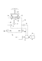
本実施形態における操作レバー20(本発明の操作手段)には、図3に示されるように、パイロット回路25が接続され、電動駆動系においては、このパイロット回路25を介して操作レバー20の操作が旋回制御装置18に伝達される。
パイロット回路25は、油圧ポンプ12を油圧源として、左パイロット弁26、右パイロット弁27、管路28、絞り29A、チェック弁29B、タンク30、左圧力センサ31、及び右圧力センサ32を備える。左圧力センサ31及び右圧力センサ32で検出された電圧信号は、旋回制御装置18に入力される。尚、前述した油圧ポンプ12には、パイロットポンプが併設され、左パイロット弁26、右パイロット弁27の操作状態に応じて、管路28の左側部分又は右側部分にパイロット圧を作用させる。尚、本実施形態では、パイロット回路25は、油圧ポンプ12をパイロットポンプとし油圧源としているが、油圧ポンプ12とは別にパイロットポンプを設け、このパイロットポンプを油圧源としてもよい。
また、絞り29A、チェック弁29Bは、管路28の左側部分及び右側部分のそれぞれに設けられているが、左右の油圧配管抵抗を均等にするために、パイロット弁26、27を起点として、管路28の左側部分及び右側部分の配管において、配管の径、長さ、曲がり等による配管損失が同等となる位置に設けられている。
さらに、図3ではパイロット弁26、27を結ぶ上側の管路は、直接タンク30に導かれているが、図4に示されるように、タンク30の前段に絞りを設けてもよい。
一方、操作レバー20を右側に操作すると、右パイロット弁27が同様に押し下げられて管路が切り替えられ、管路28の右側部分に圧油が供給される。供給された圧油は、管路28の右側部分の絞り29A、左側部分のチェック弁29Bを介して、タンク30からドレンされる。管路28の右側部分にパイロット圧が生成するとともに、管路28の左側部分には背圧が生成する。
つまり、管路28は、左パイロット弁26から右パイロット弁27に至る閉回路を形成し、パイロット弁26、27の切替状態に応じて、管路28の左側部分、右側部分の圧力状態が変化する。
これらの圧力センサ31、32としては、ダイアフラムを備えた圧力センサを採用することができ、ダイアフラムの変形を電気信号に変換する方法としては、例えば、歪みゲージ式、静電容量式、ポテンショメータを利用したもの等の公知の圧力センサを採用することができる。
図4には、本発明に係る電動アクチュエータの制御装置としての旋回制御装置18の詳細ブロック図が示されている。この旋回制御装置18は、油圧駆動系を制御するポンプコントローラ33とCAN(Controller Area Network)ライン34で通信接続されている。
操作レバー20の操作を伝達するパイロット回路25内には、前述した圧力センサ31、32とは別に、左圧力センサ35、右圧力センサ36が設けられ、これらの圧力センサ35、36で検出された圧力値は、ポンプコントローラ33に電圧信号として出力される。これは、ポンプコントローラ33が、パイロット回路25内の油圧制御のために、パイロットポンプの駆動制御を行う必要があるからである。
そして、ポンプコントローラ33に出力された圧力値は、CANライン34を介して、旋回制御装置18にも出力される。
差圧演算部181は、左圧力センサ31、右圧力センサ32からの電圧信号を圧力値に変換し、管路28における左側部分と右側部分の差圧を演算する部分である。尚、本実施形態では、電動駆動系における信号・データの取扱を、油圧駆動系における信号・データの取扱と同等とするために、電圧-圧力値変換を行っているが、電圧信号のみで差分を演算してもよい。
また、左圧力センサ31、右圧力センサ32のいずれかに故障が生じた場合、差圧演算部181は、前述したCANライン34を介してポンプコントローラ33から入力される電圧信号に基づいて、差圧を演算する。
この差圧演算部181で演算された差圧は、制御指令生成手段182に出力される。
この制御指令生成手段182で生成された制御指令は、駆動制御手段183に出力される。
駆動制御手段183は、生成された制御指令に基づいて、電流値、電圧値に変換して旋回電動モータ19に出力し、旋回電動モータ19のトルク出力を制御する部分である。
次に、前述した旋回制御装置18の作用について、図5に示されるフローチャートに基づいて説明する。
差圧演算部181は、左圧力センサ31からの電圧信号、右圧力センサ32からの電圧信号を、圧力値に変換する(処理S1)。
次に、差圧演算部181は、変換された圧力値に基づいて、管路28の左側部分と右側部分の差圧を演算して、制御指令生成手段182に出力する(処理S2)。
ここで、操作レバー20の操作が右旋回であるか、左旋回であるかの判定は、例えば、右圧力センサ32の電圧信号から左圧力センサ31の電圧信号を引き算して、その演算値が正ならば右旋回と判定し、演算値が負ならば左旋回と判定する。
尚、処理S2において差圧の算出が行われる前に、左圧力センサ31、右圧力センサ32が正常範囲を示しているかの故障判定が行われ、さらに、右圧力センサ32と右圧力センサ36の電圧信号、又は、左圧力センサ31と左圧力センサ35の電圧信号が大きな差(正常とする閾値以上の値)を示していないかの故障判定が行われる。
また、差分は、左右の圧力値を引き算することで求まる絶対値の値をいう。尚、左右の圧力値同士を引き算しなくても、各圧力センサ31、32が出力した電圧信号同士を引き算して、それを圧力値に換算してもよい。
具体的には、図6Aに示されるように、操作レバー20の操作量(傾倒量)を左右に大きくしていくと、圧力センサ31、32から出力される電圧信号は、線形的に増大するという特性がある。
そこで、差圧演算部181は、求められた差圧から、図6Bに示されるような、差圧とレバー操作量とを対比させたマップをメモリ184内に格納しておき、これを参照することにより、差圧を操作レバー20の操作量に変換する。
次に、制御指令生成手段182は、変換されたレバー操作量を旋回速度制御指令に変換して、駆動制御手段183に出力する(処理S4)。
駆動制御手段183は、例えばLPFによるフィルタ処理を行った後(処理S5)、電流値及び電圧値に変換して、旋回電動モータ19のトルク出力を制御する(処理S6)。尚、フィルタ処理はLPF以外のものを用いてもよく、さらには省略してもよい。
ここで、従来の油圧駆動の旋回装置の旋回油圧回路を、図7に基づいて説明する。
エンジン101は、油圧ポンプ102及びパイロットポンプ103の駆動源である。
油圧ポンプ102は、吐出管路104を介して流量制御弁105と接続されている。この流量制御弁105は、旋回駆動管路106A、106Bを介して旋回油圧モータ107と接続されている。
操作レバー108は、パイロット弁109、110と接続される。このパイロット弁109、110は、管路111Aを介してパイロットポンプ103と接続される。尚、この従来の油圧駆動の旋回装置では、油圧ポンプ102及びパイロットポンプを別に設けているが、油圧ポンプ102そのものを油圧源としてもよい。
パイロット弁109は、パイロット管路112Aを介して流量制御弁105の操作部105Bと接続され、パイロット弁110は、パイロット管路113Aを介して流量制御弁105の操作部105Bと接続される。
このサーボ機構はサーボピストン114、制御弁115からなっている。この制御弁115の一端は、油圧ポンプ102の吐出管路104から分岐する管路116Aと接続され、他端は流量制御弁105の下流側管路117A、117Bと接続されている。
油圧ポンプ102の斜板角は、油圧ポンプ102の吐出管路104から分岐する管路116Aから導かれる油圧ポンプ102の吐出圧P1と、下流側管路117A、117Bと合流する管路118を介して導かれる負荷圧LP1との差圧によって行われる。
逆に、P1<LP1のときは、制御弁115は、a位置に切り替わる。このため、パイロットポンプ103からのパイロット圧はサーボピストン114のa室に流入し、b室のパイロット圧はタンクへドレンされるので、サーボピストン114は左側に移動して油圧ポンプ102の斜板角が増加する。
更に、旋回駆動管路106Aから分岐する管路122A上にリリーフ弁123Bを介在させている。
また、旋回駆動管路106Bから分岐する管路122B上にリリーフ弁123Bを介在させている。これらのリリーフ弁123A、123Bはタンク121と接続されている。
これらのリリーフ弁123A、123Bは、旋回油圧モータ107の起動時、加速時等で旋回駆動管路106A、106B内に発生する高圧をリリーフしてタンク121へドレーンし、旋回油圧モータ107の損傷を防止している。
操作レバー108を左旋回側に傾倒すると、パイロット弁110がバネ力に抗して押し下げられ、パイロット弁110の入力ポートが管路111Aと連通し、パイロット管路113Aにパイロット油圧が導かれる。パイロット管路113Aに導かれたパイロット油圧は、操作部105Bに作用して、流量制御弁105はb位置に切り替えられる。
これにより、油圧ポンプ102から吐出された圧油は、旋回駆動管路106Bを介して旋回油圧モータ107に流入し、旋回油圧モータ107は、左旋回する。
図7の従来の油圧駆動の旋回装置では、前述したように、操作レバー108の傾倒により、流量制御弁105にパイロット圧を作用させても、流量制御弁105に反対側の背圧が作用しているため、流量制御弁105には、パイロット圧と背圧との差分の圧力しか作用しない。
本実施形態では、図3及び図4に示されるように、パイロット回路25中の左側部分のパイロット圧、右側部分のパイロット圧の差分に基づいて、旋回電動モータ19への制御指令を生成しているので、従来の油圧駆動型の旋回装置と同様なパイロット圧のバランスで旋回電動モータ19を駆動させることができ、従来の油圧駆動型旋回装置を使い慣れたオペレータであっても、操作時に違和感をもつことがない。
本実施形態の旋回制御装置18を用いることにより、低温環境下でも従来の油圧駆動の旋回装置と同様の操作性を実現することができる。
Claims (2)
- 正逆反転動作が可能な電動アクチュエータを制御する電動アクチュエータの制御装置であって、
前記電動アクチュエータの正逆反転動作に応じて、正方向又は逆方向に操作可能な操作手段と、
前記操作手段と接続され、当該操作手段の正方向操作又は逆方向操作に応じて、正方向パイロット圧又は逆方向パイロット圧を生成するパイロット回路と、
前記操作手段の操作方向に応じたパイロット圧、及び操作方向とは逆方向のパイロット圧の差圧を取得する差圧取得手段と、
前記差圧取得手段で取得された差圧に基づいて、前記電動アクチュエータへの制御指令を生成する制御指令生成手段と、
前記制御指令生成手段で生成された制御指令に基づいて、前記電動アクチュエータの駆動制御を行う駆動制御手段とを備えていることを特徴とする電動アクチュエータの制御装置。 - 請求項1に記載の電動アクチュエータの制御装置において、
前記差圧取得手段は、
前記パイロット回路の正方向パイロット圧を検出する正方向圧力検出部と、
前記パイロット回路の逆方向パイロット圧を検出する逆方向圧力検出部と、
前記正方向圧力検出部で検出された正方向パイロット圧、及び前記逆方向圧力部で検出された逆方向パイロット圧の差圧を演算する差圧演算部とを備えていることを特徴とする電動アクチュエータの制御装置。
Priority Applications (4)
| Application Number | Priority Date | Filing Date | Title |
|---|---|---|---|
| DE112011101713T DE112011101713T5 (de) | 2010-05-20 | 2011-05-11 | Steuervorrichtung für ein elektrisches Stellglied |
| CN201180013882.XA CN102792032B (zh) | 2010-05-20 | 2011-05-11 | 电动执行机构的控制装置 |
| KR1020127023465A KR101429041B1 (ko) | 2010-05-20 | 2011-05-11 | 전동 액츄에이터의 제어 장치 |
| US13/583,972 US9617713B2 (en) | 2010-05-20 | 2011-05-11 | Control device for an electric actuator |
Applications Claiming Priority (2)
| Application Number | Priority Date | Filing Date | Title |
|---|---|---|---|
| JP2010-116791 | 2010-05-20 | ||
| JP2010116791A JP5298069B2 (ja) | 2010-05-20 | 2010-05-20 | 電動アクチュエータの制御装置 |
Publications (1)
| Publication Number | Publication Date |
|---|---|
| WO2011145488A1 true WO2011145488A1 (ja) | 2011-11-24 |
Family
ID=44991593
Family Applications (1)
| Application Number | Title | Priority Date | Filing Date |
|---|---|---|---|
| PCT/JP2011/060808 Ceased WO2011145488A1 (ja) | 2010-05-20 | 2011-05-11 | 電動アクチュエータの制御装置 |
Country Status (6)
| Country | Link |
|---|---|
| US (1) | US9617713B2 (ja) |
| JP (1) | JP5298069B2 (ja) |
| KR (1) | KR101429041B1 (ja) |
| CN (1) | CN102792032B (ja) |
| DE (1) | DE112011101713T5 (ja) |
| WO (1) | WO2011145488A1 (ja) |
Cited By (1)
| Publication number | Priority date | Publication date | Assignee | Title |
|---|---|---|---|---|
| CN102797273A (zh) * | 2012-09-07 | 2012-11-28 | 三一重机有限公司 | 一种挖掘机工作装置先导压力采集系统及方法及挖掘机 |
Families Citing this family (3)
| Publication number | Priority date | Publication date | Assignee | Title |
|---|---|---|---|---|
| DE112015000020B4 (de) | 2014-06-04 | 2019-01-17 | Komatsu Ltd. | Baumaschinensteuersystem, Baumaschine und Baumaschinensteuerverfahren |
| JP5893219B2 (ja) * | 2014-06-04 | 2016-03-23 | 株式会社小松製作所 | 建設機械の制御システム、建設機械、及び建設機械の制御方法 |
| CN107119740B (zh) * | 2017-06-28 | 2019-07-02 | 广西柳工机械股份有限公司 | 装载机抱叉液压系统 |
Citations (5)
| Publication number | Priority date | Publication date | Assignee | Title |
|---|---|---|---|---|
| JPH09310379A (ja) * | 1996-05-21 | 1997-12-02 | Shin Caterpillar Mitsubishi Ltd | 作業機械における油圧シリンダの制振装置 |
| JP2005290674A (ja) * | 2004-03-31 | 2005-10-20 | Sumitomo (Shi) Construction Machinery Manufacturing Co Ltd | ハイブリッドショベルの操作装置 |
| JP2007139146A (ja) * | 2005-11-22 | 2007-06-07 | Kobelco Contstruction Machinery Ltd | 作業機械の制御装置 |
| JP2007192151A (ja) * | 2006-01-20 | 2007-08-02 | Nachi Fujikoshi Corp | 電動機付旋回モータ |
| WO2010137506A1 (ja) * | 2009-05-29 | 2010-12-02 | 株式会社小松製作所 | 作業機械 |
Family Cites Families (34)
| Publication number | Priority date | Publication date | Assignee | Title |
|---|---|---|---|---|
| US3675421A (en) * | 1970-11-05 | 1972-07-11 | Int Harvester Co | Low effort shuttle block selector spool modification for the manual feathering control and overspeed control for a hydrostatic transmission |
| US3865207A (en) * | 1971-04-23 | 1975-02-11 | Hyster Co | Hydraulic feed for wheel motors |
| JPS591884B2 (ja) * | 1979-09-14 | 1984-01-14 | 日立建機株式会社 | 油圧回路の制御装置 |
| JPS5825907B2 (ja) * | 1979-12-20 | 1983-05-30 | 内田油圧機器工業株式会社 | 旋回駆動制御装置 |
| US4484655A (en) * | 1980-07-01 | 1984-11-27 | Sheppard Sr Darrel J | Gearless hydraulic transmission and vehicle drive system |
| JPS57110860A (en) * | 1980-12-27 | 1982-07-09 | Hitachi Constr Mach Co Ltd | Controller of oil hydraulic system |
| JPS57184749A (en) * | 1981-05-01 | 1982-11-13 | Hitachi Constr Mach Co Ltd | Control device for hydraulic system |
| JPS5872506U (ja) * | 1981-11-10 | 1983-05-17 | 株式会社小松製作所 | 油圧閉回路装置 |
| JPS59183562U (ja) * | 1983-05-24 | 1984-12-06 | 株式会社小松製作所 | 油圧閉回路制御装置 |
| US5638677A (en) * | 1991-03-29 | 1997-06-17 | Hitachi Construction Machinery Co., Ltd. | Control device for hydraulically propelled work vehicle |
| JPH05262166A (ja) * | 1992-01-15 | 1993-10-12 | Caterpillar Inc | 油圧駆動車両用の定速走行制御装置 |
| JP3533085B2 (ja) * | 1998-04-23 | 2004-05-31 | コベルコ建機株式会社 | 建設機械のポンプ制御装置 |
| JP3884178B2 (ja) | 1998-11-27 | 2007-02-21 | 日立建機株式会社 | 旋回制御装置 |
| JP4212225B2 (ja) * | 2000-07-28 | 2009-01-21 | 株式会社小松製作所 | 建設機械における走行油圧回路 |
| JP4512283B2 (ja) * | 2001-03-12 | 2010-07-28 | 株式会社小松製作所 | ハイブリッド式建設機械 |
| EP1439337B1 (en) * | 2001-10-22 | 2008-05-21 | Yanmar Agricultural Equipment Co., Ltd. | Hydraulic transmission vehicle |
| US7607245B2 (en) | 2002-09-26 | 2009-10-27 | Hitachi Construction Machinery Co., Ltd. | Construction machine |
| JP2004150304A (ja) * | 2002-10-29 | 2004-05-27 | Komatsu Ltd | エンジンの制御装置 |
| US20090215375A1 (en) * | 2003-03-06 | 2009-08-27 | Greenvex | Fan Assemblies, Mechanical Draft Systems and Methods |
| US7114747B2 (en) * | 2003-10-20 | 2006-10-03 | Cnh America Llc | Work vehicle stabilizer |
| CN1950574B (zh) * | 2004-05-13 | 2010-09-22 | 株式会社小松制作所 | 旋转控制装置、旋转控制方法及施工机械 |
| US8328296B2 (en) * | 2004-06-10 | 2012-12-11 | Hitachi Construction Machinery Co., Ltd. | Work vehicle control device |
| US7338403B2 (en) * | 2004-08-30 | 2008-03-04 | Magna Powertrain Usa, Inc. | Torque coupling with power-operated clutch actuator |
| EP1813728A4 (en) * | 2004-11-17 | 2014-09-17 | Komatsu Mfg Co Ltd | SWIVEL CONTROL DEVICE AND CONSTRUCTION MACHINE |
| JP4524679B2 (ja) * | 2006-03-15 | 2010-08-18 | コベルコ建機株式会社 | ハイブリッド建設機械 |
| JP4732284B2 (ja) * | 2006-09-09 | 2011-07-27 | 東芝機械株式会社 | 慣性体の有する運動エネルギを電気エネルギに変換するハイブリッド型建設機械 |
| JP4898521B2 (ja) * | 2007-03-30 | 2012-03-14 | 株式会社小松製作所 | ハイブリッド建設機械 |
| JP4827789B2 (ja) * | 2007-04-18 | 2011-11-30 | カヤバ工業株式会社 | 油圧アクチュエータ速度制御装置 |
| JP5156312B2 (ja) * | 2007-09-19 | 2013-03-06 | 株式会社小松製作所 | エンジンの制御装置 |
| JP4824004B2 (ja) * | 2007-11-30 | 2011-11-24 | 住友建機株式会社 | 旋回駆動制御装置及びこれを含む建設機械 |
| JP5018473B2 (ja) * | 2007-12-28 | 2012-09-05 | 富士通セミコンダクター株式会社 | 半導体装置の製造方法 |
| JP5378061B2 (ja) * | 2009-05-08 | 2013-12-25 | カヤバ工業株式会社 | ハイブリッド建設機械の制御装置 |
| JP5489563B2 (ja) * | 2009-07-10 | 2014-05-14 | カヤバ工業株式会社 | ハイブリッド建設機械の制御装置 |
| JP5124049B2 (ja) * | 2010-02-03 | 2013-01-23 | 株式会社小松製作所 | エンジンの制御装置 |
-
2010
- 2010-05-20 JP JP2010116791A patent/JP5298069B2/ja active Active
-
2011
- 2011-05-11 CN CN201180013882.XA patent/CN102792032B/zh not_active Expired - Fee Related
- 2011-05-11 KR KR1020127023465A patent/KR101429041B1/ko not_active Expired - Fee Related
- 2011-05-11 US US13/583,972 patent/US9617713B2/en not_active Expired - Fee Related
- 2011-05-11 DE DE112011101713T patent/DE112011101713T5/de not_active Withdrawn
- 2011-05-11 WO PCT/JP2011/060808 patent/WO2011145488A1/ja not_active Ceased
Patent Citations (5)
| Publication number | Priority date | Publication date | Assignee | Title |
|---|---|---|---|---|
| JPH09310379A (ja) * | 1996-05-21 | 1997-12-02 | Shin Caterpillar Mitsubishi Ltd | 作業機械における油圧シリンダの制振装置 |
| JP2005290674A (ja) * | 2004-03-31 | 2005-10-20 | Sumitomo (Shi) Construction Machinery Manufacturing Co Ltd | ハイブリッドショベルの操作装置 |
| JP2007139146A (ja) * | 2005-11-22 | 2007-06-07 | Kobelco Contstruction Machinery Ltd | 作業機械の制御装置 |
| JP2007192151A (ja) * | 2006-01-20 | 2007-08-02 | Nachi Fujikoshi Corp | 電動機付旋回モータ |
| WO2010137506A1 (ja) * | 2009-05-29 | 2010-12-02 | 株式会社小松製作所 | 作業機械 |
Cited By (1)
| Publication number | Priority date | Publication date | Assignee | Title |
|---|---|---|---|---|
| CN102797273A (zh) * | 2012-09-07 | 2012-11-28 | 三一重机有限公司 | 一种挖掘机工作装置先导压力采集系统及方法及挖掘机 |
Also Published As
| Publication number | Publication date |
|---|---|
| CN102792032A (zh) | 2012-11-21 |
| CN102792032B (zh) | 2015-04-08 |
| JP5298069B2 (ja) | 2013-09-25 |
| KR101429041B1 (ko) | 2014-08-11 |
| DE112011101713T5 (de) | 2013-04-11 |
| US9617713B2 (en) | 2017-04-11 |
| KR20120127488A (ko) | 2012-11-21 |
| US20130073111A1 (en) | 2013-03-21 |
| JP2011241952A (ja) | 2011-12-01 |
Similar Documents
| Publication | Publication Date | Title |
|---|---|---|
| US11655611B2 (en) | Shovel | |
| KR101992510B1 (ko) | 건설 기계 | |
| CN107949706B (zh) | 作业机械 | |
| JP5785714B2 (ja) | オープンセンタ方式の掘削機用油圧システムの旋回モータ制御方法 | |
| JP6630257B2 (ja) | 建設機械 | |
| US9920780B2 (en) | Slewing drive apparatus for construction machine | |
| JP7098612B2 (ja) | 作業車両、及び、作業車両の制御方法 | |
| JP5969437B2 (ja) | 建設機械 | |
| JP5298069B2 (ja) | 電動アクチュエータの制御装置 | |
| JPWO2019003763A1 (ja) | 作業車両、及び、作業車両の制御方法 | |
| JP2011226491A (ja) | 油圧ショベルの旋回油圧回路 | |
| JP7408503B2 (ja) | 建設機械 | |
| JP2014105541A (ja) | 作業機械 | |
| JP2918170B2 (ja) | 建設機械の原動機制御装置 | |
| JP5177044B2 (ja) | 建設機械の油圧ポンプ制御装置 | |
| JP2017036689A (ja) | 油圧駆動システム | |
| JP2012159123A (ja) | 建設機械の油圧駆動装置 | |
| JP2024142668A (ja) | 異常診断システムおよび異常診断方法 | |
| JP2021195797A (ja) | 作業機械 | |
| WO2019022029A1 (ja) | ショベル | |
| JP2020051070A (ja) | 建設機械のポンプ制御装置及び建設機械 | |
| JP2007276531A (ja) | パワーステアリング装置及び車輪式建設機械 |
Legal Events
| Date | Code | Title | Description |
|---|---|---|---|
| WWE | Wipo information: entry into national phase |
Ref document number: 201180013882.X Country of ref document: CN |
|
| 121 | Ep: the epo has been informed by wipo that ep was designated in this application |
Ref document number: 11783422 Country of ref document: EP Kind code of ref document: A1 |
|
| ENP | Entry into the national phase |
Ref document number: 20127023465 Country of ref document: KR Kind code of ref document: A |
|
| WWE | Wipo information: entry into national phase |
Ref document number: 8052/DELNP/2012 Country of ref document: IN |
|
| WWE | Wipo information: entry into national phase |
Ref document number: 1120111017138 Country of ref document: DE Ref document number: 112011101713 Country of ref document: DE |
|
| WWE | Wipo information: entry into national phase |
Ref document number: 13583972 Country of ref document: US |
|
| 122 | Ep: pct application non-entry in european phase |
Ref document number: 11783422 Country of ref document: EP Kind code of ref document: A1 |