WO2011145182A1 - 光干渉断層画像計測装置 - Google Patents
光干渉断層画像計測装置 Download PDFInfo
- Publication number
- WO2011145182A1 WO2011145182A1 PCT/JP2010/058407 JP2010058407W WO2011145182A1 WO 2011145182 A1 WO2011145182 A1 WO 2011145182A1 JP 2010058407 W JP2010058407 W JP 2010058407W WO 2011145182 A1 WO2011145182 A1 WO 2011145182A1
- Authority
- WO
- WIPO (PCT)
- Prior art keywords
- eye
- partial scan
- optical
- light
- scan area
- Prior art date
- Legal status (The legal status is an assumption and is not a legal conclusion. Google has not performed a legal analysis and makes no representation as to the accuracy of the status listed.)
- Ceased
Links
Images


Classifications
-
- A—HUMAN NECESSITIES
- A61—MEDICAL OR VETERINARY SCIENCE; HYGIENE
- A61B—DIAGNOSIS; SURGERY; IDENTIFICATION
- A61B3/00—Apparatus for testing the eyes; Instruments for examining the eyes
- A61B3/10—Objective types, i.e. instruments for examining the eyes independent of the patients' perceptions or reactions
- A61B3/102—Objective types, i.e. instruments for examining the eyes independent of the patients' perceptions or reactions for optical coherence tomography [OCT]
-
- A—HUMAN NECESSITIES
- A61—MEDICAL OR VETERINARY SCIENCE; HYGIENE
- A61B—DIAGNOSIS; SURGERY; IDENTIFICATION
- A61B3/00—Apparatus for testing the eyes; Instruments for examining the eyes
- A61B3/0016—Operational features thereof
- A61B3/0025—Operational features thereof characterised by electronic signal processing, e.g. eye models
Definitions
- the present invention relates to an optical coherence tomographic image measuring apparatus (OCT apparatus) that performs optical tomographic imaging, and more particularly to an optical coherent tomographic image measuring apparatus suitable for obtaining an optical coherent tomographic image of a fundus tissue of an eye to be examined.
- OCT apparatus optical coherence tomographic image measuring apparatus
- OCT Optical Coherence Tomography
- time domain time domain
- a one-dimensional tomographic image cannot be acquired unless the reference light mirror is scanned.
- a two-dimensional scan raster scan
- two galvanometer mirrors etc.
- 3D three-dimensional scan
- Patent Document 1 discloses OCT three-dimensional distribution measurement using a MEMS (Micro Electronic Mechanical System) optical scanning mirror instead of a galvanometer mirror.
- the processing time for image acquisition is about 4.8 seconds, which is not realistic.
- accurate measurement data cannot be obtained due to fixation eye movement or blinking of the subject's eye during the measurement time of several seconds as described above, resulting in measurement failure. Therefore, the current OCT of each company reduces the spatial resolution so that the measurement is completed in about 1 to 1.5 seconds.
- one example of an optical coherence tomography that has already been sold is one with specifications that the camera performance is 53 k scans / second, and 3D scanning of 9 mm ⁇ 9 mm is performed in 1.6 seconds.
- the time required for one B scan is About 9.7 msec.
- about 166 B scans can be performed in 1.6 seconds, and the resolution in the X-axis direction is calculated to be about 17.6 ⁇ m and the resolution in the Y-axis direction is calculated to be about 54.2 ⁇ m.
- the resolution in the depth (Z-axis) direction is 5 to 6 ⁇ m in the Fourier domain method and about 10 ⁇ m in the time domain method, so in this example, the resolution in the Y-axis direction is particularly insufficient.
- image processing is performed so as to complement between lines, so that accuracy is inferior.
- the clinical issue is whether to give priority to spatial resolution or measurement time.
- An object of the present invention is to provide an optical coherence tomographic image measurement apparatus capable of solving the above-described problems and performing 3D imaging of the retina of an eye to be examined without acquiring a tomographic image with a large objective lens and a wide angle of view. It is in.
- a light source that emits partially coherent light, a light beam emitted from the light source, a signal light that passes through a placement position of the eye to be examined, and the eye placement to be examined
- the signal light after passing through the position of the eye to be examined and the reference light passing through the different optical path are interfered with each other by being divided into reference light passing through a different optical path from the optical path passing through the position.
- An interference optical system for generating light, a diffraction grating for splitting the interference light generated by the interference optical system, a photosensor array for detecting the split interference light, and the photosensor array detected In an optical coherence tomographic image measuring apparatus having a fast Fourier transformer that performs fast Fourier transform of a signal and a control unit that images the output of the fast Fourier transformer and displays or records the optical coherent tomographic image Based on the control of the control unit, the signal light includes scanning means for two-dimensionally scanning a predetermined partial scan area of the eye to be examined at a predetermined scanning speed, and the eye to be examined is two-dimensionally scanned by the scanning means.
- the entire measurement range of the eye to be examined is divided into a plurality of partial scan areas, each partial scan area is sequentially scanned by the scanning means, and optical coherence tomographic images obtained from each partial scan area are panorama synthesized.
- a configuration for acquiring an optical coherence tomographic image of the measurement range of the eye to be examined was adopted.
- each partial scan area is a minute area, and a wide range of measurement areas are covered by photographing a plurality of partial scan areas, and images obtained in each partial scan area are panorama synthesized.
- the image of the entire measurement area can be acquired by this, the effect of fixation movement and blinking in each partial scan area can be reduced, and the measurement time for each partial scan can be shortened. It has an excellent effect that the measurement time and resolution can be changed by variously selecting the number of measurement areas (number of acquired images), size, etc. .
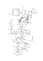
- reference numeral 1 is a high-intensity light emitting diode (Super Luminescent Diode: SLD) that emits partially coherent light, and has low coherence (coherence is necessary) for observing a tomographic image.
- SLD Super Luminescent Diode
- This is a light source having a small number of properties.
- the center wavelength is assumed to generate light in the infrared (invisible) band of 840 nm, for example.
- the light beam from the light source 1 is collimated by the lens 2, and the light beam passing through the mirror 3 is expanded into a light beam of a predetermined size via the lenses 4 and 5, and then a beam splitter (BS: light
- BS beam splitter
- the optical path is divided into four directions: an optical path 6a on the light source side, a reference optical path 6b, a search optical path 6c, and a detection optical path 6d.
- another light source for example, an SLD or LD (Laser Diode: semiconductor laser) that emits visible light (for example, red having a wavelength of about 670 nm) is provided, and this is used as a light source 1 using a dichroic mirror or the like. By matching with the optical axis, it can be used as an auxiliary light source for confirming the optical path of the light beam with visible light against invisible infrared rays for measurement.
- SLD SystemLD
- LD Laser Diode: semiconductor laser
- the light beam traveling in the reference light path 6 b is reflected by the reference light mirror 9, and the light beam reflected by the reference light mirror 9 returns through the lens 8 to the reference light path 6 b.
- the light beam traveling along the search optical path 6c is incident on the galvanometer mirror 10a attached to the galvanometer 10.
- the light beam reflected by the galvanometer mirror 10a is reflected by the galvanometer mirror 11a of the second galvanometer 11, and the light beam is passed through these two galvanometer mirrors 10a or 11a in a direction perpendicular to the optical axis.
- Each can be scanned one-dimensionally.
- the galvanometer 11 can perform scanning in the X-axis direction
- the galvanometer 10 can perform scanning in the Y-axis direction.
- galvanometer mirrors 10a and 11a constitute first and second optical scanning means for scanning the light beam of the search light at the same frequency as the line sensor array constituting the spectrometer 21, respectively.
- the light beams scanned by the galvanometer mirrors 10a and 11a enter the eye 15 (the anterior eye portion 15a or the fundus 15b) of the object to be observed after passing through the lenses 12, 13, and 14.
- the lenses 12 and 13 constitute a focusing optical system that can be adjusted according to the diopter of the eye to be examined (myopia, hyperopia, etc.), and change the focal position of the light beam according to the optical characteristics of the target object. It is a focus adjustment means.
- the positions of the lenses 12 and 13 can be adjusted in the optical axis direction according to the operation of a predetermined mechanism (not shown).
- the lenses 12 and 13 and the lens 14 constitute a telecentric optical system so that the conjugate relationship between the galvanometer mirror and the eye to be examined is kept substantially constant.
- the light beam incident on the eye 15 is converged in a dot shape at a predetermined position on the fundus 15b, for example, to be in a focused state.
- This point-focused light beam can scan the fundus 15b of the eye to be examined in a line shape or a circle shape by scanning with galvanometer mirrors 10a and 11a (light scanning means).
- galvanometer mirrors 10a and 11a light scanning means.
- FIGS. 2A to 2C which will be described later, a rectangular small area is two-dimensionally scanned, and a similar rectangular area is scanned in a grid pattern while shifting the position.
- Panorama image a rectangular small area is two-dimensionally scanned, and a similar rectangular area is scanned in a grid pattern while shifting the position.
- Reflected light from the fundus 15b of the eye 15 to be inspected travels backward through the optical system described above, that is, reaches the beam splitter (BS) 7 via the lenses 12, 13, and 14 and the galvanometer mirrors 10a and 11a.
- the reflected light from the eye 15 to be inspected that travels backward in the search optical path 6c and passes through the beam splitter 7 is combined with the reference light that returns from the reference optical path 6b, thereby generating interference light in the detection optical path 6d.
- This interference light passes through the detection aperture (pinhole) 17 through the lens 16 as detection light, and further enters the diffraction grating 19 disposed at an inclination with respect to the optical axis through the lens 18.
- the detection light passing through the diffraction grating 19 is detected by a spectrometer 21 including a line sensor array through a lens 20.
- the output signal of the spectrometer 21 is converted into a spectrum distribution signal by a fast Fourier transformer (FFT) 22 and input to a PC (personal computer) 23.
- FFT fast Fourier transformer
- the PC 23 can measure the three-dimensional distribution of the biological components of the eye to be examined by performing image processing on the detection light information input from the fast Fourier transformer 22.
- the PC 23 controls the overall operation of the optical system (particularly, the two galvanometers 10 and 11), and the measurement result of the three-dimensional distribution of the measurement target tissue in the eye to be examined is displayed on a display device 24 such as a liquid crystal television monitor. Control is performed such as outputting and displaying, and transferring the measurement result to the storage device 25 and storing it as necessary.
- the PC 23 has a keyboard and a pointing device (such as a mouse), and can perform settings for measurement control via these user interface means.
- the pinhole 17 provided in the optical system has a predetermined pinhole-shaped detection aperture with a gap limited in the scanning direction of the optical scanning means, and detects noise caused by unnecessary stray light and scattered light.
- the background light amount level is reduced, thereby improving the gradation of the signal component with respect to the video signal from the image sensor.
- the pinhole 17 may be a small square-shaped opening, and this opening can also be configured by stacking two pieces of slit-shaped parts formed in a thin plate at right angles.
- the light beam incident on the eye 15 to be examined is focused and focused in a dot shape at a predetermined position of the fundus 15b, for example, and the fundus 15b of the eye to be examined is made into a line shape or a circle shape by the galvanometer mirrors 10a and 11a.
- a small rectangular area is two-dimensionally scanned, and a similar rectangular area is scanned in a grid pattern while shifting the position. Then, panorama synthesis is performed on images obtained from these areas.
- the measurement time in each area can be shortened, and the effects of eye movement and blinking can be reduced. It is possible to obtain a more accurate measurement result by panoramicly combining images obtained in each area later.
- the imaging speed by the spectrometer 21 (line sensor array), the fast Fourier transformer 22 and the PC 23 of this apparatus is 40 k (scan / sec).
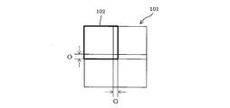
- FIG. 2A shows the entire measurement range 101 divided by four partial scan areas 102 each having a rectangular shape (square).
- the scan range of the two galvanometers 10 and 11 is controlled by the PC 23 so that the scan size of one partial scan area 102 is 6 mm ⁇ 6 mm, and the image acquisition point is 200 pt ⁇ 200 pt (that is, the resolution is 30 ⁇ m). ).
- the entire measurement range 101 is 11 ⁇ 11 mm, and adjacent partial scan areas 102 have 1 mm overlap portions O that overlap each other.
- the scan of one partial scan area 102 can be processed in one second, so that no burden is imposed on the subject. If the galvanometers 10 and 11 are controlled at a short interval each time one scan is completed and the adjacent partial scan areas 102, 102... Are sequentially photographed, four scan images are obtained as shown in the figure. It is done.
- an image of the entire measurement range 101 is formed by performing a process of overlapping adjacent 1 mm edges of the four scan images by a known panorama synthesis process.
- the overlap portion O of the partial scan area 102 can be used for alignment by pattern matching in the panorama synthesis process, and a known complement or blend process is performed so that the image connection is good in the overlapped portion. Can do. Since the overlap portions O of 1 mm are overlapped with each other in the adjacent partial scan areas 102, the image of the entire measurement range 101 finally obtained has a size of 11 mm ⁇ 11 mm.
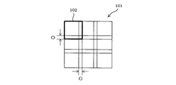
- FIG. 2B shows measurement control when a higher resolution scan is desired.
- FIG. 2B shows the entire measurement range 101 divided by nine rectangular (square) partial scan areas 102.
- one scan size is set to 4 mm ⁇ 4 mm, and the image acquisition point is set to 200 pt ⁇ 200 pt (that is, the resolution is 20 ⁇ m).
- Adjacent partial scan areas 102 have 1 mm overlap portions O that overlap each other.
- one partial scan area 102 can be scanned in one second.
- a wide range of measurement results are obtained by obtaining nine images.
- an image of the entire measurement range 101 of 10 mm ⁇ 10 mm is finally obtained by panoramic synthesis processing of nine images.
- FIG. 2C shows measurement control when it is desired to perform a shorter scan.
- FIG. 2C shows the entire measurement range 101 divided by four partial scan areas 102 each having a rectangular shape (square).
- the method shown in FIGS. 2A and 2B does not give any burden to normal subjects because each scan is performed in one second, but it is difficult for elderly and infant subjects. There is a case. Therefore, in the case of FIG. 2C, the size of one partial scan area 102 is 4 mm ⁇ 4 mm, and adjacent partial scan areas 102 have 1 mm overlapping portions O that overlap each other.
- the image acquisition point is 133 pt ⁇ 133 pt in order to keep the resolution at 30 ⁇ m
- one scan can be completed in 0.44 seconds.
- the finally obtained scan image range is 7 mm ⁇ 7 mm.
- the probability of failure in each measurement is reduced, so that reliable measurement is possible although the measurement range is narrow.
- the scan speed of the galvanometer mirrors 10a and 11a is set to a predetermined value, the scan size and the acquisition point (element for determining resolution) are determined, and the measurement region is further divided into several images.
- Measurement control parameters for controlling measurement conditions such as whether to capture and combine in panorama processing can be selected in various ways using user interface means of the PC 23 including a keyboard and pointing device (such as a mouse).
- various panoramic patterns similar to those shown in FIGS. 2A to 2C can be set by the PC 23 controlling the operation of the two galvanometers 10 and 11 of the optical system, and the command can be set via the user interface means of the PC 23. Can be set.
- the scan range can be changed, each partial scan area is made into a minute area, and a wide range of measurement areas are covered by photographing a plurality of partial scan areas, and obtained in each partial scan area.
- the entire measurement area can be acquired by panoramic synthesis of the image, the effects of fixation micromotion and blinking in each partial scan area can be reduced, and the measurement time for each partial scan can be shortened. Therefore, there is an excellent effect of being able to cope with the subject (the elderly or a patient with a disease).
- the measurement time and resolution can be changed by variously selecting the number of partial scan areas (number of acquired images) and size, a measurement effect different from panoramic photography of the fundus camera can be expected.
- the above-described panoramic pattern shown in FIGS. 2A to 2C is an example, and various measurement demands can be met by changing the number of overlapping and the overlapping distance.
- the objective lens (14) since it is not necessary to acquire a tomographic image with a wide angle of view when photographing one partial scan area, the objective lens (14) does not have to be large. Therefore, there are excellent effects that the configuration of the apparatus is simple and inexpensive, and the panoramic function enables a three-dimensional scan of the optical coherence tomographic image with a wide range and an arbitrary resolution.
- the gaze of the eye to be examined is reliably guided in the measurement of each partial scan area constituting a wider measurement range.
- FIG. 3 shows an example in which an internal fixation lamp 29 having a plurality of lighting parts as a fixation target is arranged in the main body.
- the internal fixation lamp 29 is composed of LEDs arranged in a matrix. When a specific LED of the internal fixation lamp 29 is turned on according to the control of the PC 23, the emitted light is converted into a lens 30, a total reflection mirror 28, The line of sight of the subject eye 15 can be guided and fixed in the direction of the LED that is incident on the eye 15 by the perforated total reflection mirror 26 via the lens 27 and the internal fixation lamp 29 is lit. 3 is the same as that of FIG. Alternatively, a liquid crystal display (LCD) and a backlight unit are arranged instead of the position of the internal fixation lamp 29, and a specific portion is brightly displayed to guide and fix the line of sight of the eye 15 to be examined. It may be.
- LCD liquid crystal display
- the internal fixation lamp 29 corresponding to each partial scan area is switched on and turned on in a direction suitable for the measurement of the partial scan area.
- the line of sight is reliably guided for a short time during measurement of each partial scan area, and each area can be measured accurately, resulting in panorama synthesis. It is possible to accurately measure a fundus image in a wider range by performing.
- the lighting position of the internal fixation lamp 29 can be recorded in the storage device 25 by the PC 23 in correspondence with information indicating which part of the fundus is currently being measured.
- the optical coherence tomographic image measurement can be performed in a wider measurement range by switching on and lighting a plurality of predetermined fixation targets and guiding the line of sight in a direction suitable for the measurement of each partial scan area. .
- the optical coherence tomographic image measurement apparatus of the present invention can be used for three-dimensional measurement of the tissue of the fundus of the eye to be examined.
Landscapes
- Health & Medical Sciences (AREA)
- Life Sciences & Earth Sciences (AREA)
- Biomedical Technology (AREA)
- Heart & Thoracic Surgery (AREA)
- Radiology & Medical Imaging (AREA)
- Biophysics (AREA)
- Ophthalmology & Optometry (AREA)
- Engineering & Computer Science (AREA)
- Nuclear Medicine, Radiotherapy & Molecular Imaging (AREA)
- Physics & Mathematics (AREA)
- Medical Informatics (AREA)
- Molecular Biology (AREA)
- Surgery (AREA)
- Animal Behavior & Ethology (AREA)
- General Health & Medical Sciences (AREA)
- Public Health (AREA)
- Veterinary Medicine (AREA)
- Eye Examination Apparatus (AREA)
Abstract
信号光で被検眼の所定の部分スキャンエリアを2次元スキャンする光走査手段としてガルバノメーター10、11を有し、被検眼15を2次元スキャンする場合、被検眼15の眼底の測定範囲全体を複数の部分スキャンエリアに分割して各部分スキャンエリアを順次スキャンし、各部分スキャンエリアから得られた光干渉断層画像をパノラマ合成することにより被検眼の測定範囲の光干渉断層画像を取得する。各部分スキャンエリアの測定においてはマトリクス状にLEDが配置して成る内部固視灯29の所定のLEDを点灯させ、その各部分スキャンエリアの測定に必要な方向に被検眼15の視線を誘導する。
Description
本発明は光断層画像化を行う光干渉断層画像計測装置(OCT装置)、特に被検眼の眼底組織の光干渉断層画像取得などに好適な光干渉断層画像計測装置に関するものである。
現在OCT(Optical Coherence Tomography:光干渉断層画像計測装置)の主流は、フーリエドメイン(周波数領域)OCTである。従来のタイムドメイン(時間領域)方式では参照光ミラーをスキャンしなければ1次元断層像が取得できなかったが、フーリエドメイン方式によれば参照光ミラーを固定したまま1次元断層像が得られるため、さらに2つのガルバノミラーなどによる2次元スキャン(ラスタースキャン)を行うことで、実質的に3次元(以下必要に応じて3Dとも表記する)スキャンとなり、高速に断層像の3D画像を取得することが可能となった。下記の特許文献1ではガルバノミラーの替わりにMEMS(Micro Electronic Mechanical System)光走査ミラーを用いたOCT3次元分布測定が開示されている。
特開2009-119153号公報
フーリエドメインOCTでは、3次元スキャンの処理速度が高速になったとはいえ、広範囲、あるいは高精細な画像を得るためにはそれなりの時間がかかる。通常、断層像(Bスキャン=2次元スキャン)を1枚取得する場合、Aスキャン(Z軸方向への1次元スキャン)をX軸方向に移動しながら100~500ポイントとることで画像が構築される。ここで、仮にAスキャンを512ポイントとるBスキャンと同様の密度で3Dスキャンを行った場合、512×512=262144スキャンとなり、カメラの速度を30k(scan/sec)とした場合、3Dスキャンの画像取得には約8.7秒かかってしまうことになる。
非常に高速な55k(scan/sec)のカメラを用いたとしても、画像取得の処理時間は約4.8秒となりこれは現実的ではない。眼科撮影の場合、上記のような数秒規模の測定時間では、被検眼の固視微動や瞬目などにより正確な撮影データが得られず、測定失敗となってしまう。そこで、現状各社のOCTは空間分解能を落として約1~1.5秒程度で測定が終了するようにしている。
たとえばすでに販売されている光干渉断層計の一例においては、カメラの性能が53kスキャン/秒、9mm×9mmの3Dスキャンを1.6秒で行うというスペックのものがある。上記のように、仮にAスキャン(Z軸方向へのスキャン)をX軸方向に512ポイントとるBスキャンで3Dスキャン(Y軸方向へのスキャン)を行うと、1回のBスキャンにかかる時間は約9.7msecである。これにより1.6secの間に約166回のBスキャンができることになり、X軸方向の分解能は約17.6μm、Y軸方向の分解能は約54.2μmと計算される。
通常、フーリエドメイン方式では、深さ(Z軸)方向の分解能は5~6μm、タイムドメイン方式でも10μm程度であることから、この例では特にY軸方向の分解能が不十分であり、実際に画像表示する場合にはライン間を補完するような画像処理を行うことになるため、正確性が劣ることになる。
以上のことから、現在のOCTにおける3Dスキャンは網膜の詳細な構造を3Dで構築するには程遠く、網膜各層の厚さのマッピングをするにとどまっているのが現状である。
さらに、被検者によっては、上記のような約1~1.5秒の測定時間であっても、固視微動や瞬目により、正確な測定データが得られない場合がある。例えば高齢者や網膜疾患がある被検者等は固視が安定しないため、より短時間で測定を終わらせる必要があり、このためにはスキャンエリアを小さくするか空間分解能を落とす必要がある。
以上のように、被検眼に対する3Dスキャンを行う場合、臨床上、問題となるのは空間分解能と測定時間のどちらを優先させるかということになる。
しかし、高速カメラは高額であり、さらに、スキャン範囲を広くすることは、眼底カメラにおける高画角化と同じであり、対物レンズを大きくしたり、ワーキングディスタンスを短くする、などの対応が必要となる。しかしながら、このように対物レンズを大きくした場合は、装置が大型化し結果として装置が高額になり、ワーキングディスタンスを短くした場合は、被検者への圧迫感や開瞼のしづらさなどを生じる、などの問題がある。
本発明の課題は、上記問題を解決し、大きな対物レンズ、広い画角で断層像を取得することなく、被検眼の網膜の3D撮影を行うことができる光干渉断層画像計測装置を提供することにある。
以上の課題を解決するため、本発明によれば、部分的コヒーレント光を射出する光源と、該光源から出射された光ビームを、被検眼の配置位置を経由する信号光と、該被検眼配置位置を経由する光路とは異なる光路を経由する参照光とに二分するとともに、前記被検眼配置位置を経由した後の信号光と、前記異なる光路を経由した参照光とを互いに重畳することにより干渉光を生成する干渉光学系と、該干渉光学系で生成された前記干渉光を分光するための回折格子と、該分光された干渉光を検出する光センサアレイと、該光センサアレイが検出した信号を高速フーリエ変換する高速フーリエ変換器と、該高速フーリエ変換器の出力を画像化して光干渉断層画像として表示または記録する制御部とを有する光干渉断層画像計測装置において、前記制御部の制御に基づき、前記信号光で前記被検眼の所定の部分スキャンエリアを所定のスキャンスピードにより、2次元スキャンする走査手段を有し、前記走査手段により前記被検眼を2次元スキャンする場合、前記被検眼の測定範囲全体を複数の部分スキャンエリアに分割して各部分スキャンエリアを前記走査手段により順次スキャンし、各部分スキャンエリアから得られた光干渉断層画像をパノラマ合成することにより前記被検眼の測定範囲の光干渉断層画像を取得する構成を採用した。
上記構成によれば、1つ1つの部分スキャンエリアを微小な領域とし、複数の部分スキャンエリアの撮影により広い範囲の測定領域をカバーし、各部分スキャンエリアで得られた画像をパノラマ合成することにより測定領域全体の画像を取得することができ、各部分スキャンエリアにおける固視微動や瞬目の影響を小さくすることができ、部分スキャン一つ一つの測定時間を短くできるので、被検者(高齢者や疾病を持つ患者)に対応でき、また、測定エリアの数(取得画像の数)、サイズなどを種々選択することにより測定時間や分解能を変更することができる、という優れた効果がある。
以下、本発明を実施するための最良の形態の一例として、被検眼眼底組織の光干渉断層画像計測を行うOCT装置に関する実施例を示す。
図1において、符号1で示すものは、部分的コヒーレント光を射出する高輝度の発光ダイオード(Super Luminescent Diode:SLD)であり、断層画像を観察するために必要な低干渉性の(干渉性が少ない)性質を有する光源である。中心波長は、例えばそれぞれ840nmという赤外線(不可視)帯域の光を発生するものとする。光源1からの光ビームは、レンズ2でコリメートされ、ミラー3を介した光ビームは、レンズ4、5を介して所定の大きさの光ビームへと拡大された後、ビームスプリッター(BS:光分割部材)7に入射する。ビームスプリッター7の位置において、光路は、光源側の光路6a、参照光路6b、探索光路6c、検出光路6dの4方向に分割されている。
さらに不図示の別の光源、たとえば、可視光(例えば、波長670nm程度の赤色)の光を射出するSLDまたはLD(Laser Diode:半導体レーザー)を設け、これを、ダイクロイックミラーなどを用いて光源1の光軸と一致させることで、測定用の不可視の赤外線に対して、可視光で光ビームの光路を確認するための補助光源として利用することができる。
参照光路6bを進む光ビームは参照光ミラー9で反射され、参照光ミラー9で反射された光ビームは、レンズ8を介して参照光路6bを戻る。
一方、探索光路6cを進む光ビームは、ガルバノメーター10に装着されたガルバノミラー10aに入射する。ガルバノミラー10aで反射された光ビームは、第2のガルバノメーター11のガルバノミラー11aで反射し、これら2つのガルバノミラー10aまたは11aを介して、光軸に対して直交する方向に、光ビームをそれぞれ1次元的に走査させることができる。
例えば、二つのガルバノミラー10a、11aの一方を固定して一方だけによる走査を行えば、光軸(Z軸)に垂直な方向のX軸方向またはY軸方向の走査が可能である。図1の場合、たとえば、ガルバノメーター11によりX軸方向の走査を、ガルバノメーター10によりY軸方向の走査を行なうことができる。
あるいは、二つのガルバノミラー10a、11aをともに同一の周波数で動作させて、それぞれを駆動する波形の種類や振幅、位相等を適宜設定すれば、XY面内方向において、任意のライン状の走査、またはサークル状等の走査が可能になる。これらガルバノミラー10aと11aは、それぞれ探索光の光ビームを、分光計21を構成するラインセンサアレイと同じ周波数で走査するための第1と第2の光走査手段を構成している。
ガルバノミラー10a、11aによって走査された光ビームは、レンズ12、13、14を介した後、観察対象物体の被検眼15(前眼部15a、または眼底15b)に入射する。ここで、レンズ12、13は、被検眼の視度(近視や遠視等)に応じて調節可能なフォーカシング光学系を構成しており、対象物体の光学特性に応じて光ビームの焦点位置を変化させる焦点調節手段となっている。レンズ12および13の位置は所定の機構(不図示)の動作に応じて光軸方向に調整可能である。また、レンズ12、13とレンズ14は、テレセントリック光学系を構成しており、ガルバノミラーと被検眼との共役関係がほぼ一定に保たれるように構成されている。
被検眼15に入射した光ビームは、例えば眼底15bの所定位置において、点状に収束してフォーカス状態となる。この点状にフォーカスされた光ビームは、ガルバノミラー10a、11a(光走査手段)の走査によって、被検眼の眼底15bを、ライン状またはサークル状等に走査することが可能であるが、本実施例では、後述の図2A~図2Cに示すように矩形状の小さいエリアを2次元走査し、さらには同様の矩形状エリアを、位置をずらしながら格子状に走査し、これらの各エリアから得た画像をパノラマ合成する。
被検眼15の眼底15bからの反射光は、前述した光学系を逆進し、すなわちレンズ12、13、14、ガルバノミラー10a、11aを経由して、ビームスプリッター(BS)7に至る。探索光路6cを逆進し、ビームスプリッター7を透過した被検眼15からの反射光は、参照光路6bから戻ってくる参照光と合成され、これにより検出光路6dに干渉光が発生する。
この干渉光は、検出光としてレンズ16を介して検出開口(ピンホール)17を通過し、さらにレンズ18を介して、光軸に対して傾斜して配置された回折格子19に入射される。回折格子19を介した検出光は、レンズ20を介してラインセンサアレイから成る分光計21にて検出される。
分光計21の出力信号は高速フーリエ変換器(FFT)22によってスペクトル分布信号に変換されPC(パーソナルコンピュータ)23に入力される。
PC23において、高速フーリエ変換器22から入力された検出光の情報に対して画像処理を行うことにより、被検眼の生体成分の3次元分布を測定することができる。
PC23は、光学系(特に2つのガルバノメーター10、11等)の動作全般を制御するとともに、被検眼中の測定対象の組織の3次元分布の測定結果を、液晶テレビモニター等の表示装置24に出力して表示させ、また、測定結果は必要に応じて記憶装置25に転送して記憶させるなどの制御を行う。また、PC23は、キーボードやポインティングデバイス(マウスなど)を有し、これらのユーザーインターフェース手段を介して測定制御のための設定を行うことができる。
上記光学系において設けられたピンホール17は、光走査手段の走査方向に間隙の制限された所定のピンホール状の検出開口を有し、不要な迷光や散乱光によるノイズを排除して、検出される干渉信号のSN(信号対雑音特性)を向上させるとともに、バックグラウンドの光量レベルを減らすことによって、撮像素子からの映像信号に関して信号成分の階調性を向上させる効果を有する。ピンホール17は、微小な正方形状の開口であっても良く、この開口は、薄板に形成されたスリット状の部品を直交させて2枚重ね合わせることによっても構成することができる。
上記構成において、被検眼15に入射した光ビームを例えば眼底15bの所定位置において、点状に収束してフォーカスさせ、ガルバノミラー10a、11aによって、被検眼の眼底15bをライン状またはサークル状等に走査することができるが、本実施例では、図2A~図2Cに示すように矩形状の小さいエリアを2次元走査し、さらには同様の矩形状エリアを、位置をずらしながら格子状に走査し、これらの各エリアから得た画像をパノラマ合成する。
このように、実際に3Dスキャンしたい範囲を小さなエリアに分割し、後にパノラマ合成することにより、個々のエリアにおける測定時間は短くすることができ、固視微動や瞬目の影響を小さくすることができ、そして、各エリアで得た画像を後にパノラマ合成することによって、より正確な測定結果を得ることができる。
以下、次に具体的なスキャン手順を示す。ここで本装置の分光計21(ラインセンサアレイ)~高速フーリエ変換器22~PC23による撮影スピードは40k(scan/sec)とする。
図2Aは、それぞれ矩形(正方形)の4つの部分スキャンエリア102で分割した測定範囲101全体を示している。
図2AはPC23によって2つのガルバノメーター10、11のスキャン範囲を制御し、1つの部分スキャンエリア102のスキャンサイズが6mm×6mmとなるように、また画像取得ポイントを200pt×200pt(つまり分解能は30μm)となるように設定している。測定範囲101全体は11×11mmであり、隣接する部分スキャンエリア102どうしは互いに重畳する1mmのオーバーラップ部分Oを有している。
この場合、1つの部分スキャンエリア102のスキャンを1秒で処理できることになるため、被検者に負担を与えない。1つのスキャンを終えるたびに少しの間をおいてガルバノメーター10、11を制御して隣接する部分スキャンエリア102、102…を順次撮影するようにすれば図示のように4枚のスキャン画像が得られる。
そして公知のパノラマ合成処理によって、4枚のスキャン画像の隣接する互いの1mmの辺縁を重ねる処理を行うことにより、測定範囲101全体の画像が形成される。部分スキャンエリア102のオーバーラップ部分Oはパノラマ合成処理において、パターン照合による位置合せなどに用いることができ、また重畳部分では画像の繋がりが良好になるように、公知の補完やブレンド処理を行なうことができる。そして、それぞれ隣接する部分スキャンエリア102で互いに1mmのオーバーラップ部分Oが重畳されるから、最終的に得られる測定範囲101全体の画像は11mm×11mmのサイズとなる。
このような測定制御を行うことにより、比較的広い範囲のスキャンが可能となり、全体の検査時間は4秒を超えることになるが、その間、被検者の視線が変わることのないよう、不図示の固視灯を注視させ、一定の方向に被検眼の視線を誘導し、固定する(図2B、図2Cの例においても同じ。また、内部固視灯の例については図3に示す)。
図2Bはより高分解能のスキャンを行ないたい場合の測定制御を示している。図2Bは、それぞれ矩形(正方形)の9つの部分スキャンエリア102で分割した測定範囲101全体を示している。
図2Bでは、上記同様の制御により、1つのスキャンサイズが4mm×4mmとなるように、また画像取得ポイントを200pt×200pt(つまり分解能は20μm)となるように設定する。また、隣接する部分スキャンエリア102どうしは互いに重畳する1mmのオーバーラップ部分Oを有している。
この場合も1つの部分スキャンエリア102のスキャンが1秒で処理できる。高分解能であるがスキャンエリアが狭くなったのを補うため、9枚の画像を得ることにより広範囲の測定結果を得るようにする。この場合は、9枚の画像のパノラマ合成処理により、最終的に10mm×10mmの測定範囲101全体の画像が得られる。
また、図2Cはより短時間のスキャンを行いたい場合の測定制御を示している。図2Cは、それぞれ矩形(正方形)の4つの部分スキャンエリア102で分割した測定範囲101全体を示している。
図2A、図2Bで示した手法は1回ごとのスキャンを1秒で行うので、通常の被検者にとってはなんら負担を与えないものであるが、高齢者や乳幼児の被検者にとっては難しい場合がある。そこで図2Cの場合は1つの部分スキャンエリア102のサイズが4mm×4mm、隣接する部分スキャンエリア102どうしは互いに重畳する1mmのオーバーラップ部分Oを有している。
分解能は30μmに保つため画像取得ポイントを133pt×133ptとすると、1つのスキャンは0.44秒で完了することができる。ただし、この場合、4枚画像を取得しても最終的に得られるスキャン画像範囲は7mm×7mmということになる。しかし1つのスキャンが短時間で済むため、個々の測定で失敗する確率が低くなることから、測定範囲は狭いものの確実な測定が可能となる。
以上のように、ガルバノミラー10a、11aのスキャンのスピードを所定の値に設定するとともに、スキャンサイズと取得ポイント(分解能を決定する要素)を決定し、さらに測定領域を何枚の画像に分割して撮影しパノラマ処理で結合するかなど測定条件を制御するための測定制御パラメータは、キーボードやポインティングデバイス(マウスなど)から成るPC23のユーザーインターフェース手段を用いて種々選択できるように構成しておく。特に、図2A~図2C、あるいはこれらに類似の種々のパノラマパターンはPC23が光学系の2つのガルバノメーター10、11の動作を制御することにより設定でき、その指令はPC23のユーザーインターフェース手段を介して設定することができる。
以上のように、スキャン範囲を変更可能とし、1つ1つの部分スキャンエリアを微小な領域とし、複数の部分スキャンエリアの撮影により広い範囲の測定領域をカバーし、各部分スキャンエリアで得られた画像をパノラマ合成することにより測定領域全体の画像を取得することができ、各部分スキャンエリアにおける固視微動や瞬目の影響を小さくすることができ、部分スキャン一つ一つの測定時間を短くできるので、被検者(高齢者や疾病を持つ患者)に対応できる、という優れた効果がある。
また、部分スキャンエリアの数(取得画像の数)やサイズなどを種々選択することにより測定時間や分解能を変更することができるため、眼底カメラのパノラマ撮影とは異なる測定効果が期待できる。図2A~図2Cに示した上記のパノラマパターンは一例であり、重ね合わせの枚数や重ね合わせの距離を変えることにより様々な測定需要に応えることができる。
また、1つの部分スキャンエリアの撮影においては、広い画角で断層像を取得する必要がないことから、対物レンズ(14)が大きくならなくて済む。そのため、装置の構成が簡単安価になり、パノラマ機能により広範囲かつ任意の解像度での光干渉断層画像の3次元スキャンが可能となる、という優れた効果がある。
さらに、図3のように内部固視灯29を設け、測定エリアごとに視線誘導方向を制御することによって、より広い測定範囲を構成する各部分スキャンエリアの測定において確実に被検眼の視線を誘導し、各エリアの測定において固視微動や瞬目の影響を小さくすることができ、正確な画像を取得することができる。
図3は本体内に固視目標として複数の点灯部を有する内部固視灯29を配置した場合の例を示している。
内部固視灯29はマトリクス状にLEDが配置して成るもので、PC23の制御に応じて内部固視灯29の特定のLEDを点灯させると、出射した光はレンズ30、全反射ミラー28、レンズ27を介して穴あき全反射ミラー26によって被検眼15に入射され、内部固視灯29の点灯させたLEDの方向へ被検眼15の視線を誘導、固定することができる。図3のその他の構成は図1と同様である。あるいは、上記の内部固視灯29の位置に、代りに液晶ディスプレイ(LCD)とバックライトのユニットを配置し、特定の箇所を明るく表示するなどして被検眼15の視線を誘導、固定するようにしてもよい。
したがって、後にパノラマ合成する図2A~図2Cの各部分スキャンエリアの測定時に、それぞれ各部分スキャンエリアに対応する内部固視灯29を切り換えて点灯させ、その部分スキャンエリアの測定に適した方向に点灯している箇所に視線を誘導することによって、各部分スキャンエリアの測定中の短時間の間、確実に視線誘導が行われ、各エリアの測定を正確に行えるようになり、結果としてパノラマ合成を行うことによってより広い範囲の眼底像を正確に測定することが可能となる。内部固視灯29の点灯位置は、PC23により、現在眼底のどの部分を測定しているか、という情報に対応させて記憶装置25に記録することができる。
以上のようにして、複数の所定の固視目標を切り換えて点灯し、各部分スキャンエリアの測定に適した方向に視線誘導することにより、さらに広い測定範囲で光干渉断層画像計測が可能になる。
本発明の光干渉断層画像計測装置は、被検眼眼底の組織の3次元測定に利用することができる。
1 光源
2 レンズ
3 ミラー
4、5 レンズ
7 ビームスプリッター
8 レンズ
10、11 ガルバノメーター
10a、11a ガルバノミラー
12、13、14 レンズ
15 被検眼
16、18、20 レンズ
19 回折格子
21 分光計(ラインセンサアレイ)
22 高速フーリエ変換器(FFT)
23 PC(パーソナルコンピュータ)
25 記憶装置
28 全反射ミラー
29 内部固視灯
30 レンズ
101 測定範囲
102 部分スキャンエリア
2 レンズ
3 ミラー
4、5 レンズ
7 ビームスプリッター
8 レンズ
10、11 ガルバノメーター
10a、11a ガルバノミラー
12、13、14 レンズ
15 被検眼
16、18、20 レンズ
19 回折格子
21 分光計(ラインセンサアレイ)
22 高速フーリエ変換器(FFT)
23 PC(パーソナルコンピュータ)
25 記憶装置
28 全反射ミラー
29 内部固視灯
30 レンズ
101 測定範囲
102 部分スキャンエリア
Claims (3)
- 部分的コヒーレント光を射出する光源と、
該光源から出射された光ビームを、被検眼の配置位置を経由する信号光と、該被検眼配置位置を経由する光路とは異なる光路を経由する参照光とに二分するとともに、前記被検眼配置位置を経由した後の信号光と、前記異なる光路を経由した参照光とを互いに重畳することにより干渉光を生成する干渉光学系と、
該干渉光学系で生成された前記干渉光を分光するための回折格子と、
該分光された干渉光を検出する光センサアレイと、
該光センサアレイが検出した信号を高速フーリエ変換する高速フーリエ変換器と、
該高速フーリエ変換器の出力を画像化して光干渉断層画像として表示または記録する制御部とを有する光干渉断層画像計測装置において、
前記制御部の制御に基づき、前記信号光で前記被検眼の所定の部分スキャンエリアを所定のスキャンスピードにより、2次元スキャンする光走査手段を有し、
前記光走査手段により前記被検眼を2次元スキャンする場合、前記被検眼の測定範囲全体を複数の部分スキャンエリアに分割して各部分スキャンエリアを前記光走査手段により順次スキャンし、各部分スキャンエリアから得られた光干渉断層画像をパノラマ合成することにより前記被検眼の測定範囲の光干渉断層画像を取得することを特徴とする光干渉断層画像計測装置。 - 請求項1に記載の光干渉断層画像計測装置において、前記測定範囲内において、前記各部分スキャンエリアは隣接する部分スキャンエリアと相互に所定量重畳していることを特徴とする光干渉断層画像計測装置。
- 請求項1又は2に記載の光干渉断層画像計測装置において、前記被検眼により視認可能な複数の固視目標を設け、特定の前記部分スキャンエリアのスキャンの際、当該部分スキャンエリアに対応する所定の固視目標を切り換えて点灯させることによりスキャンする部分スキャンエリアに対応する方向に前記被検眼の視線を誘導し、当該部分スキャンエリアのスキャンを行うことを特徴とする光干渉断層画像計測装置。
Priority Applications (1)
| Application Number | Priority Date | Filing Date | Title |
|---|---|---|---|
| PCT/JP2010/058407 WO2011145182A1 (ja) | 2010-05-19 | 2010-05-19 | 光干渉断層画像計測装置 |
Applications Claiming Priority (1)
| Application Number | Priority Date | Filing Date | Title |
|---|---|---|---|
| PCT/JP2010/058407 WO2011145182A1 (ja) | 2010-05-19 | 2010-05-19 | 光干渉断層画像計測装置 |
Publications (1)
| Publication Number | Publication Date |
|---|---|
| WO2011145182A1 true WO2011145182A1 (ja) | 2011-11-24 |
Family
ID=44991306
Family Applications (1)
| Application Number | Title | Priority Date | Filing Date |
|---|---|---|---|
| PCT/JP2010/058407 Ceased WO2011145182A1 (ja) | 2010-05-19 | 2010-05-19 | 光干渉断層画像計測装置 |
Country Status (1)
| Country | Link |
|---|---|
| WO (1) | WO2011145182A1 (ja) |
Cited By (4)
| Publication number | Priority date | Publication date | Assignee | Title |
|---|---|---|---|---|
| JP2016131845A (ja) * | 2015-01-22 | 2016-07-25 | キヤノン株式会社 | 眼科装置及びその制御方法、並びに、プログラム |
| JP2019118421A (ja) * | 2017-12-28 | 2019-07-22 | 株式会社トプコン | 眼科撮影装置、その制御方法、プログラム、及び記録媒体 |
| JP2019118419A (ja) * | 2017-12-28 | 2019-07-22 | 株式会社トプコン | 眼科撮影装置、その制御方法、プログラム、及び記録媒体 |
| JP2022027879A (ja) * | 2017-12-28 | 2022-02-14 | 株式会社トプコン | 眼科撮影装置、その制御方法、プログラム、及び記録媒体 |
Citations (1)
| Publication number | Priority date | Publication date | Assignee | Title |
|---|---|---|---|---|
| JP2009183332A (ja) * | 2008-02-04 | 2009-08-20 | Topcon Corp | 眼底観察装置、眼底画像処理装置及びプログラム |
-
2010
- 2010-05-19 WO PCT/JP2010/058407 patent/WO2011145182A1/ja not_active Ceased
Patent Citations (1)
| Publication number | Priority date | Publication date | Assignee | Title |
|---|---|---|---|---|
| JP2009183332A (ja) * | 2008-02-04 | 2009-08-20 | Topcon Corp | 眼底観察装置、眼底画像処理装置及びプログラム |
Cited By (6)
| Publication number | Priority date | Publication date | Assignee | Title |
|---|---|---|---|---|
| JP2016131845A (ja) * | 2015-01-22 | 2016-07-25 | キヤノン株式会社 | 眼科装置及びその制御方法、並びに、プログラム |
| JP2019118421A (ja) * | 2017-12-28 | 2019-07-22 | 株式会社トプコン | 眼科撮影装置、その制御方法、プログラム、及び記録媒体 |
| JP2019118419A (ja) * | 2017-12-28 | 2019-07-22 | 株式会社トプコン | 眼科撮影装置、その制御方法、プログラム、及び記録媒体 |
| JP2022027879A (ja) * | 2017-12-28 | 2022-02-14 | 株式会社トプコン | 眼科撮影装置、その制御方法、プログラム、及び記録媒体 |
| JP7050488B2 (ja) | 2017-12-28 | 2022-04-08 | 株式会社トプコン | 眼科撮影装置、その制御方法、プログラム、及び記録媒体 |
| JP7134324B2 (ja) | 2017-12-28 | 2022-09-09 | 株式会社トプコン | 眼科撮影装置、その制御方法、プログラム、及び記録媒体 |
Similar Documents
| Publication | Publication Date | Title |
|---|---|---|
| CN114886374B (zh) | 眼科装置及其控制方法、程序和存储介质 | |
| JP5563087B2 (ja) | 視野検査システム | |
| JP5512682B2 (ja) | 眼球運動、特に眼底の運動の測定装置および測定方法 | |
| CN109008942A (zh) | 一种基于裂隙灯平台的全眼光学相干断层成像装置及成像方法 | |
| JP5513101B2 (ja) | 光画像計測装置 | |
| US9989351B2 (en) | Tomographic image capturing device | |
| JP6756516B2 (ja) | 眼科撮影装置 | |
| WO2011145182A1 (ja) | 光干渉断層画像計測装置 | |
| JPWO2013085042A1 (ja) | 眼底観察装置 | |
| JP7096392B2 (ja) | 眼科装置 | |
| JP2017195944A (ja) | 眼科撮影装置 | |
| JP2016022312A (ja) | 眼科撮影装置及びその制御方法 | |
| JP2019170464A (ja) | 眼科装置 | |
| JP2018068630A (ja) | 断層画像取得装置及び方法 | |
| JP2024127325A (ja) | 光画像形成装置、光画像形成装置の制御方法、及び、プログラム | |
| JP2020130266A (ja) | 眼科装置 | |
| JP7580252B2 (ja) | 眼科撮影装置 | |
| JP2012223428A (ja) | 眼科装置 | |
| JP2022060588A (ja) | 眼科装置、及び眼科装置の制御方法 | |
| JP6557388B2 (ja) | 眼科撮影装置 | |
| JP2018078977A (ja) | 眼科撮影装置 | |
| JP2012176162A (ja) | 眼底観察装置 | |
| JP5913519B2 (ja) | 眼底観察装置 | |
| JP2019205822A (ja) | 撮像装置およびその制御方法 | |
| JP6646722B2 (ja) | 眼科装置 |
Legal Events
| Date | Code | Title | Description |
|---|---|---|---|
| 121 | Ep: the epo has been informed by wipo that ep was designated in this application |
Ref document number: 10851746 Country of ref document: EP Kind code of ref document: A1 |
|
| NENP | Non-entry into the national phase |
Ref country code: DE |
|
| 122 | Ep: pct application non-entry in european phase |
Ref document number: 10851746 Country of ref document: EP Kind code of ref document: A1 |
|
| NENP | Non-entry into the national phase |
Ref country code: JP |