WO2011141995A1 - 転写装置及び方法、並びにコンピュータプログラム - Google Patents
転写装置及び方法、並びにコンピュータプログラム Download PDFInfo
- Publication number
- WO2011141995A1 WO2011141995A1 PCT/JP2010/057952 JP2010057952W WO2011141995A1 WO 2011141995 A1 WO2011141995 A1 WO 2011141995A1 JP 2010057952 W JP2010057952 W JP 2010057952W WO 2011141995 A1 WO2011141995 A1 WO 2011141995A1
- Authority
- WO
- WIPO (PCT)
- Prior art keywords
- mold
- holding
- transfer
- pressing
- deformation
- Prior art date
- Legal status (The legal status is an assumption and is not a legal conclusion. Google has not performed a legal analysis and makes no representation as to the accuracy of the status listed.)
- Ceased
Links
Images





Classifications
-
- B—PERFORMING OPERATIONS; TRANSPORTING
- B29—WORKING OF PLASTICS; WORKING OF SUBSTANCES IN A PLASTIC STATE IN GENERAL
- B29C—SHAPING OR JOINING OF PLASTICS; SHAPING OF MATERIAL IN A PLASTIC STATE, NOT OTHERWISE PROVIDED FOR; AFTER-TREATMENT OF THE SHAPED PRODUCTS, e.g. REPAIRING
- B29C59/00—Surface shaping of articles, e.g. embossing; Apparatus therefor
- B29C59/02—Surface shaping of articles, e.g. embossing; Apparatus therefor by mechanical means, e.g. pressing
-
- B—PERFORMING OPERATIONS; TRANSPORTING
- B29—WORKING OF PLASTICS; WORKING OF SUBSTANCES IN A PLASTIC STATE IN GENERAL
- B29C—SHAPING OR JOINING OF PLASTICS; SHAPING OF MATERIAL IN A PLASTIC STATE, NOT OTHERWISE PROVIDED FOR; AFTER-TREATMENT OF THE SHAPED PRODUCTS, e.g. REPAIRING
- B29C33/00—Moulds or cores; Details thereof or accessories therefor
- B29C33/30—Mounting, exchanging or centering
- B29C33/305—Mounting of moulds or mould support plates
-
- B—PERFORMING OPERATIONS; TRANSPORTING
- B29—WORKING OF PLASTICS; WORKING OF SUBSTANCES IN A PLASTIC STATE IN GENERAL
- B29C—SHAPING OR JOINING OF PLASTICS; SHAPING OF MATERIAL IN A PLASTIC STATE, NOT OTHERWISE PROVIDED FOR; AFTER-TREATMENT OF THE SHAPED PRODUCTS, e.g. REPAIRING
- B29C59/00—Surface shaping of articles, e.g. embossing; Apparatus therefor
- B29C59/02—Surface shaping of articles, e.g. embossing; Apparatus therefor by mechanical means, e.g. pressing
- B29C59/022—Surface shaping of articles, e.g. embossing; Apparatus therefor by mechanical means, e.g. pressing characterised by the disposition or the configuration, e.g. dimensions, of the embossments or the shaping tools therefor
- B29C2059/023—Microembossing
-
- B—PERFORMING OPERATIONS; TRANSPORTING
- B29—WORKING OF PLASTICS; WORKING OF SUBSTANCES IN A PLASTIC STATE IN GENERAL
- B29C—SHAPING OR JOINING OF PLASTICS; SHAPING OF MATERIAL IN A PLASTIC STATE, NOT OTHERWISE PROVIDED FOR; AFTER-TREATMENT OF THE SHAPED PRODUCTS, e.g. REPAIRING
- B29C33/00—Moulds or cores; Details thereof or accessories therefor
- B29C33/42—Moulds or cores; Details thereof or accessories therefor characterised by the shape of the moulding surface, e.g. ribs or grooves
- B29C33/424—Moulding surfaces provided with means for marking or patterning
Definitions
- the present invention relates to a transfer apparatus and method for transferring a concavo-convex pattern to a transfer target by pressing a mold on which the concavo-convex pattern is formed to the transfer target, and a technical field of a computer program.
- the holding member that holds the mold and the holding member that holds the transferred object are moved so as to approach each other, thereby closely contacting and pressing the mold and the transferred object. Then, by separating the closely attached mold and transferred object (so-called mold release operation), a pattern formed on the mold surface is transferred to the transferred object surface. At this time, the mold and the transfer target are close to each other in parallel and closely contacted in parallel, and are released in parallel. For this reason, as the area of the mold increases, entrainment of bubbles between the mold and the transfer target increases, resulting in a technical problem that the accuracy of the transferred pattern deteriorates.
- Patent Document 1 discloses an apparatus configuration in which a mold is bent and deformed by fixing the mold to a holding member having a slope formed in advance. Discloses an apparatus configuration including means for bending a mold using air pressure. As an apparatus for separating the closely attached mold and transferred object, Patent Document 3 discloses a configuration of a peeling apparatus that bends the mold by applying a negative pressure in the chamber.
- the present invention has been made in view of the above-described technical problems.
- a mold, a transferred object, or a mold can be obtained by more suitably performing deformation of the mold. It is an object of the present invention to provide a transfer apparatus and method, and a computer program that can appropriately suppress the pattern formed on the pattern and the pattern transferred to the transfer target from being damaged, and that can accurately transfer the pattern. To do.
- a first transfer device of the present invention is a transfer device that transfers a pattern formed on a mold to a transfer target, a mold holding means for holding the mold, and the transfer target.
- a second transfer apparatus of the present invention transfers a pattern formed on a first mold to a first surface of a transfer target, and the pattern formed on a second mold.
- a transfer device for transferring to a second surface of the transfer object wherein the first mold holding means for holding the first mold, the second mold holding means for holding the second mold, and the transfer target
- the first mold and the transfer object are mutually
- the first deformation means for moving the first mold holding means to deform the first mold at the time of contact immediately before being pressed and at the time of releasing after pressing, the second mold,
- a second deforming means for deforming the second mold by moving the second mold holding means at at least one of the time immediately before the transfer body is pressed against each other and at the time of releasing after pressing. .
- a third transfer device of the present invention is a transfer device that operates in response to an instruction from a control device and transfers a pattern formed on a mold to a transfer target.
- a mold holding means for holding the mold In accordance with an instruction from the control device, a mold holding means for holding the mold, a transferred object holding means for holding the transferred object in accordance with an instruction from the control device, and an instruction from the control device
- the mold holding means is moved to deform the mold at least one of contact immediately before the mold and the transfer object are pressed against each other and release after pressing.
- the And a deformation means that.
- a first transfer method of the present invention is a transfer method in a transfer apparatus that transfers a pattern formed on a mold to a transfer target, a mold holding step for holding the mold, A transferred object holding process for holding the transferred object; a pressing process for bringing the mold and the transferred object into contact with each other and pressing each other; a mold releasing process for releasing the mold and the transferred object that are in close contact with each other; In at least one of the pressing step and the mold releasing step, a deformation step of deforming the mold by moving a member holding the mold is provided.
- a second transfer method of the present invention transfers a pattern formed on a first mold to a first surface of a transfer target, and the pattern formed on a second mold.
- a transfer method in a transfer device for transferring to a second surface of the transfer object a first mold holding step for holding the first mold, a second mold holding step for holding the second mold, A transferred object holding step for holding the transferred object, a first pressing step for contacting and pressing the first mold and the transferred object, and a contact between the second mold and the transferred object.
- a step, the first pressing step and the first In at least one of the mold process, in at least one of the first deformation process of deforming the first mold by moving a member holding the first mold, the second pressing process, and the second mold release process, A second deformation step of deforming the second mold by moving a member holding the second mold.
- a computer program of the present invention is a computer program for operating a transfer device that transfers a pattern formed on a mold to a transfer target, and a mold holding step for holding the mold; A transferred object holding process for holding the transferred object, a pressing process for bringing the mold and the transferred object into contact with each other, and pressing the mold and the transferred object, and releasing the mold.
- the transfer device is caused to execute a deformation step of moving the member holding the mold to deform the mold.
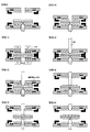
- FIG. 6 is a schematic diagram showing the operation of each part of the imprint apparatus in a transfer operation.
- FIG. 6 is a schematic diagram showing the operation of each part of the imprint apparatus in a transfer operation. It is a graph which illustrates the time change of the pressing force of a mold clamp controlled by a control part.
- Embodiment which concerns on the transfer apparatus of this invention is a transfer apparatus which transfers the pattern formed in the mold to a to-be-transferred body, Comprising: The mold holding means by which the said mold is hold
- the mold held by the mold holding unit is pressed against the transfer target held by the transfer target holding unit, so that the unevenness formed on the mold, etc.
- the pattern is transferred to the transfer target.
- the mold holding means is provided with a suction mechanism including a mold, for example, a vacuum pump described in detail later.
- the transferred object holding means is a member configured to hold and fix the transferred object so as not to hinder the close contact with the mold.
- the transferred object holding means may be configured to hold the transferred object by holding the transferred object from two opposite directions.
- the pressing means moves one or both of the mold and the transferred body that are held as described above to move the surface on which the pattern of the mold is formed (hereinafter referred to as a pattern surface) and the transferred body.
- the surface to which the pattern is transferred (hereinafter referred to as a transfer surface) is in close contact with each other and can be pressed against each other.
- the pressing unit is, for example, an actuator that realizes the above-described pressing by moving the mold holding unit or the transfer target holding unit. Further, the configuration and operation of the pressing means may be the same as the pressing means provided in a known transfer device.
- the mold release means is configured to release the mold in close contact and the transfer target.
- the release means fixes one of the mold holding means and the transfer target holding means and applies a force (hereinafter referred to as a release force) in a direction to separate the other, thereby releasing the mold. Realize the mold.
- the deformation means is configured to move the mold holding means and perform an operation that causes deformation of the mold.
- the “deformation of the mold” typically means that at least a part of the pattern surface of the mold held relative to the transfer surface of the transfer object has a predetermined angle with respect to the transfer surface. And showing a tilted deformation. More generally, a part of the pattern surface of the mold faces the transfer surface of the transfer object, and at the same time, the other part does not face the transfer surface of the transfer object.
- the cross-sectional shape or three-dimensional appearance shape that intersects the pattern surface typically changes somewhat compared to the pattern surface of the mold before deformation, which is typically parallel to the transfer surface in the entire region. means.
- Such “deformation of the mold” is reversible and can be released by the deformation means returning the position of the mold holding means to the position before the deformation of the mold as will be described later.
- the deformation may be a plastic or elastic deformation that occurs in the mold.
- the deformation means of the present embodiment is, for example, a mechanism that changes the position of the mold holding means in a direction perpendicular to the surface to be bent so that the mold is placed on a flat surface. It may be.
- the deformation means performs the above-described deformation of the mold at least one of when the mold and the transfer target are in contact immediately before being pressed against each other and at the time of releasing after pressing. In other words, in a state where the mold is deformed by the operation of the deforming means, at least one of the operation of bringing the mold and the transferred body into contact with the pressing means and the operation of releasing the mold and the transferred body by the releasing means. Is implemented.
- the mold is deformed by the above-described operation of the deforming means when the mold and the transferred object are in contact with each other, the pattern surface of the mold that is inclined due to the deformation is close to the transferred surface of the transferred object. It will contact sequentially from the side.
- the deforming means moves the mold holding means so that the outer peripheral portion of the mold is pressed or pulled in the direction opposite to the transfer target, the mold has a relative outer periphery of the pattern surface with respect to the transfer target. And the center part is deformed so as to be relatively close to the transfer target.
- the pressing means contacts the mold and the transfer object in this state, the mold first comes into contact with the transfer surface of the transfer object at the center of the pattern surface, and then the contact sequentially proceeds toward the outer periphery.
- the deforming means it is possible to suitably suppress the vacancy generated on the close contact surface as the contact between the mold and the transfer target proceeds, and appropriately leaving the vacancy on the close contact surface after the close contact. .
- the holes mixed in the contact portion are pushed out to the outer peripheral portion as the contact proceeds, and the adhesion surface Removed from.
- the pattern of the holes cannot be accurately transferred, which may lead to a decrease in yield.
- the alignment of the mold and the transfer object performed after the transfer object is installed can be performed with high accuracy in a short time. These are useful in the operation of a nanoimprint transfer apparatus that is expected to process a large amount of transfer target material by continuous transfer.
- the mold release means releases the mold and the transferred object while the deformation means deforms the mold and simultaneously moves the mold holding means.
- the deformation causes an inclination of the pattern surface of the mold with respect to the transfer surface.
- a part of the pattern surface that is relatively separated from the transfer surface of the transfer target due to the inclination is peeled off from the transfer surface and released.
- the mold deformed as described above is released from the transfer surface of the transfer object in a part of the outer peripheral portion of the pattern surface, and there is a gap on the contact surface. Arise.
- the close contact force acts on the close contact surface so as to maintain the close contact state.
- the mold release means it is necessary for the mold release means to perform pressing and traction for mold release with a force larger than the adhesion force applied to the adhesion surface between the mold and the transfer object. It is known that such an adhesive force varies depending on the precision of the pattern transferred between the mold and the transfer target and the degree of deterioration of the release agent formed on the pattern surface of the mold.
- the contact surface when there is a gap on the contact surface, the contact surface does not act on the portion corresponding to the gap, so the contact force is relatively weak in the vicinity of the gap, and the mold can be easily released. Yes.
- the gap generated by the deformation of the mold as a release start point that triggers the release, it is possible to realize the release between the mold and the transfer target with a relatively weak force.
- the mold is deformed so as to form a gap in the outer periphery of the pattern surface of the mold as described above, the end of the contact surface between the pattern surface and the transfer surface of the transfer object is released from the mold at the outer periphery of the mold. Since the gap is formed by the mold release, the mold can be deformed with a relatively weak force.
- the mold since the mold is deformed by the operation of the mold holding means, it is possible to apply a desired amount of deformation to the mold at a desired timing. For this reason, unlike the conventional configuration in which the amount of deformation is determined according to the adhesive force on the adhesive surface between the mold and the transfer target, for example, the deterioration of the release agent formed on the pattern surface of the mold by continuous transfer. Accordingly, the technical problem that the adhesive force on the adhesive surface changes and as a result the amount of deformation of the mold changes can be solved preferably. For this reason, stable deformation of the mold can be realized.
- the deforming means is configured to hold the mold and the transfer target body against the mold holding means for holding while the mold and the transfer target are pressed against each other. The mold is not deformed while the mold is attached and while the mold held by the mold holding means is removed.
- the mold when the mold is attached to the mold holding means, it may be required to adjust the mold alignment with respect to the mold holding means.
- By performing the alignment adjustment it is possible to align the pattern surface of the held mold at a desired position by moving the mold holding means thereafter. At this time, when the mold is deformed, it is not possible to appropriately adjust the alignment between the mold holding means and the pattern on the mold. Therefore, it is preferable that the mold is attached without being deformed.
- the mold holding means is also required to maintain a shape corresponding to the deformation of the mold at least during the attaching or removing operation. .
- the shape of a mold holding means will be restrict
- the deformation of the mold is performed for the purpose of eliminating voids generated on the contact surface with the transfer target and creating a mold release starting point that triggers mold release.
- the amount of deformation of the mold for achieving the above may be affected by the material of the mold and transfer conditions. For this reason, the amount of deformation of the mold is not necessarily constant.
- the shape of the mold holding means when the shape of the mold holding means is determined in accordance with the deformation of one mold, the desired deformation cannot be realized with respect to another mold. In some cases, it may not be possible to hold. Specifically, when the shape of the mold holding means is determined according to the deformation of the mold, conditions such as the material and thickness of the mold that can be held are determined. It will be limited. In the transfer using a mold, various different molds may be used. Therefore, it is not preferable in terms of use of the apparatus to limit the conditions of a usable mold.
- the mold is not deformed when being attached to and removed from the mold holding means, and the mold is deformed according to the conditions of the mold by the subsequent operation of the mold holding means.
- the transfer operation can be realized using various molds without limiting the conditions.
- the transfer device further includes a mounting unit on which the mold is mounted, and the deformation unit is provided on a surface of the mounting unit on which the mold is mounted. The mold is deformed by pressing the mold in a perpendicular direction.
- the mold is held by the mold holding means while being placed on the mold placing means. At this time, the mold is typically in contact with and supported by the mold mounting means on the surface opposite to the pattern surface. “Placing” in this aspect does not necessarily indicate a state in which the mold is disposed vertically above the mold mounting means, but includes a state in which the mold is supported by contacting each other as described above. It is a comprehensive concept.
- the mold holding means of this aspect is, for example, provided on the mounting means, and is configured to realize holding by some means with respect to the mold.
- Such mold holding means is configured to be movable by pressing the mold by the deformation means.
- the mold holding means has a mechanism that can move in a direction perpendicular to the mounting surface on which the mold of the mounting means formed on the mounting means is placed, and the mold is moved along with the movement. Is configured to be deformable.
- the mold holding means holds the mold on the same surface as the surface of the mounting means on which the mold is mounted, and the deformation means includes the mold of the mounting means.
- the mold may be deformed by moving the mold holding means so as to form a recess with respect to the surface to be placed.
- the mold holding means in a state where the deformation of the mold by the deformation means is not performed, the mold holding means forms a surface substantially the same as the mold placement surface, and holds the surface in contact with the mold on the surface.
- the mold holding means is moved in a direction away from the mold so as to form a recess with respect to the substantially same surface as the mold mounting surface.
- the mold Due to the action of these two forces, the mold is bent in such a manner that the portion held by the mold holding means is pulled in the direction in which the mold holding means moves.
- the mold holding means of this aspect may be an aspect that is disposed in a recess formed in advance on the mounting means. According to such an aspect, the above-described configuration can be realized relatively easily by moving the mold holding means within the recess. In particular, in the case where the deforming means has a configuration such as a clamp that presses the mold holding means through the mold as described above, the above-described configuration can be more suitably realized.
- an elastic member is arranged at the bottom of the recess formed in the mounting means, and the mold holding means is arranged as instructed by the elastic member.
- the elastic member is deformed such as contraction in accordance with the movement of the mold holding unit by the deforming unit. For this reason, when the mold holding means is moved in the elastic member direction by the deformation means, the mold holding means receives a predetermined elastic force from the elastic member.
- the spring coefficient that determines the elastic force of the elastic member is determined based on the upper limit of the deformation amount of the mold based on the material of the mold. Preferably, at a position where the predetermined amount of deformation of the mold reaches an upper limit, the force acting on the mold holding means moved by the deformation means is balanced with the elastic force acting on the mold holding means by the elastic member. Is done. Note that the upper limit of the deformation amount of the mold at this time is an allowable amount set with a margin with respect to the deformation amount that causes damage such as damage to the mold.
- the elastic member serves as a cushion against deformation of the mold. For this reason, the mold does not deform beyond the upper limit of the predetermined deformation amount determined according to the elastic force of the elastic member or the like by the movement of the mold holding means by the deformation means. For this reason, it can avoid suitably that a break etc. arise in a mold.
- This configuration makes it possible to realize the operation of deforming the mold with a relatively simple configuration, which is beneficial in terms of the device configuration.
- the deforming means releases the deformation of the mold after the mold and the transfer target body are in contact with each other.
- the deformation means moves the mold holding means so as to release the deformation of the mold after the pattern surface of the mold comes into contact with the transfer surface of the transfer target. For this reason, at the time of pressing for the transfer between the mold and the transferred object by the subsequent pressing means, the mold is pressed against the transferred object in a flat state with no deformation.
- the pressing by the pressing means for transferring the mold and the transferred body means that the mold and the transferred body are moved after a part or the whole of the pattern surface of the mold comes into contact with the transferred body by the operation of the pressing means. It is the meaning which shows the state which has exerted pressure mutually in the state pressurized by the press means. Therefore, in this aspect, the mold holding unit releases the deformation of the mold after the mold is brought into contact with the transfer target by the pressing unit, and the transfer by pressurization is performed after the deformation is released.
- the deformation means may be configured to release the deformation of the mold, except when the advantage is not obtained by the above-described deformation of the mold. Specifically, after being separated from the transfer medium by a releasing operation by the releasing means, the deforming means may move the mold holding means so as to release the deformation of the mold.
- the deforming means moves the mold holding means to deform the mold by pressing the mold against the mold holding means. .
- the deforming means of this aspect applies a pressing force to the mold holding means indirectly by pressing the mold held by the mold holding means in the direction of the mold holding means, thereby causing the movement.
- the deformation means of this aspect includes, for example, a pressing member such as a clamp mechanism that contacts the mold and can press the mold.
- the deforming means presses the mold held by the mold holding means in a direction perpendicular to the surface and toward the surface.
- the deforming means presses the mold with a predetermined pressing force set in advance, and moves the position of the mold holding means by a desired distance by the pressing.
- the mold bends with a deformation amount corresponding to the pressing force in accordance with the movement of the mold holding means and the pressing by the deformation means. In this way, the deformation means realizes a desired deformation amount of the mold.
- transformation means mentioned above is a structure which applies a pressing force with respect to a mold, it can be used also for the purpose of strengthening holding
- the mold holding means holds the mold by suction.
- the mold holding means of this aspect is, for example, an adsorption member having an adsorption groove connected to a vacuum pump or the like, and the mold is brought into contact with the adsorption part when the inside of the adsorption groove becomes negative pressure by the operation of the vacuum pump Adsorb the back side.
- an adsorbing portion holding of the mold is realized.
- holding of the mold relatively easily and enjoy the effects according to the various aspects described above.
- holding of the mold may be realized by using other members.
- the mold holding means may be configured to suck the mold at the outer peripheral portion of the surface on which the pattern of the mold is not formed.
- the mold when the mold is deformed, the position is changed by the deforming means while the mold holding means holds the outer periphery of the mold. According to such deformation, the mold is deformed in such a manner that the position of the outer peripheral portion of the pattern surface with respect to the transfer object changes relative to the central portion.
- the deformation means is the above-described clamp mechanism, the deformation is performed so that the outer peripheral portion of the mold is relatively separated from the transfer target.
- the holes generated in the close contact surface move to the outer periphery of the mold as the contact between the mold and the transfer target proceeds, and are suitably excluded from the close contact surface.
- release is caused by deformation at the outer peripheral portion of the pattern surface which is relatively easy to release, so that easy deformation is possible.
- the pattern formed on the first mold is transferred to the first surface of the transfer object, and the pattern formed on the second mold is transferred to the transfer object.
- a transfer device for transferring to a second surface wherein the first mold holding means for holding the first mold, the second mold holding means for holding the second mold, and the transferred body are held.
- first mold release means for releasing the first mold and the transfer target
- second mold release means for releasing the second mold and the transfer target
- the first deformation means for moving the first mold holding means to deform the first mold, and the second mold and the transfer object are mutually connected at least one of when contacting and after releasing.
- a second deformation means for moving the second mold holding means to deform the second mold at the time of contact immediately before being pressed and at the time of releasing after pressing.
- the transfer apparatus of the present invention there are two types of molds, such as a first mold holding means for holding the first mold and a second mold holding means for holding the second mold. There is a means for holding each. Of these two molds, the first mold was pressed against the first surface of the transferred body and the second mold was pressed against the second surface of the transferred body, thereby forming each mold. Pattern transfer is performed.
- the first pressing means operates at least one of the first mold holding means and the transferred object holding means to bring the first mold and the first surface of the transferred object into close contact and press each other.
- the second pressing means operates at least one of the second mold holding means and the transferred object holding means to bring the second mold and the second surface of the transferred object into close contact and press each other.
- Each pressing may be performed in succession or may be performed simultaneously.
- the first pressing means and the second pressing means are configured to transfer the transferred body between the first mold and the second mold. Transfer may be performed by sandwiching and pressing from both sides simultaneously.
- the first mold release unit operates at least one of the first mold holding unit and the transfer target holding unit to release the first mold from the transfer target.
- the second mold release means operates at least one of the second mold holding means and the transferred object holding means to release the second mold from the transferred object.
- Each mold release is preferably performed in a row, but may be performed at the same time.
- the first mold release unit releases the first mold from the object to be transferred in a state where the object to be transferred and the second mold are fixed.
- the first mold holding means is moved in the direction to be moved.
- the second release means performs the release by moving the holding means for holding the other in the direction to release the mold while one of the transfer object and the second mold is fixed.
- the first deformation means moves the first mold holding means for deforming the first mold, as in the transfer device of the first embodiment described above. Specifically, the first deforming means is at least when the first mold is contacted with the first mold by the first pressing means, and when the first mold is released from the transferred object by the first mold means. At one timing, the first mold holding means is moved to deform the first mold.
- the second deformation means also moves the second mold holding means for deforming the second mold.
- the second deforming means is at least one of when the second pressing means contacts the second mold and the transferred object, and when the second mold releasing means releases the second mold and the transferred object. At this timing, the second mold holding means is moved to deform the second mold.
- the first deforming unit releases the deformation of the first mold after the first mold and the transfer target are in contact with each other
- the second deformation means releases the deformation of the second mold after the second mold and the transfer target body are in contact with each other.
- the mold is not deformed at the time of attachment to and removal from each mold holding means, and the subsequent operation of the mold holding means. It is the structure which deform
- the third embodiment according to the transfer device of the present invention is a transfer device that operates in response to an instruction from a control device and transfers a pattern formed on a mold to a transfer target.
- a mold holding means for holding the mold a transferred object holding means for holding the transferred object according to an instruction from the control device, and a mold and the mold according to an instruction from the control device
- a pressing means for bringing the transferred bodies into contact with each other a mold release means for releasing the mold and the transferred body in close contact with each other according to instructions from the control device, and instructions from the control device
- a deformation means for deforming the mold by moving the mold holding means at least one of when the mold and the transferred object are in contact immediately before being pressed against each other and at the time of releasing after pressing.
- Embodiment which concerns on the transfer method of this invention is a transfer method in the transfer apparatus which transcribe
- the pattern formed on the first mold is transferred to the first surface of the transfer object, and the pattern formed on the second mold is transferred to the transfer object.
- a transfer method in a transfer device for transferring to a second surface wherein a first mold holding step for holding the first mold, a second mold holding step for holding the second mold, and holding the transfer object A transferred object holding process, a first pressing process for contacting and pressing the first mold and the transferred object, and a second pressing the second mold and the transferred object and pressing each other.
- the second A second deformation step of deforming the second mold by moving a member holding the mold in at least one of the first deforming step of deforming the first mold by moving the member holding the first mold, the second pressing step, and the second mold releasing step, the second A second deformation step of deforming the second mold by moving a member holding the mold.
- An embodiment according to the computer program of the present invention is a computer program for operating a transfer device that transfers a pattern formed on a mold to a transfer target, the mold holding step for holding the mold, and the transfer target A transferred body holding step for holding the body, a pressing step for bringing the mold and the transferred body into contact with each other and pressing each other, a releasing step for releasing the mold and the transferred body that are in close contact with each other, and the pressing
- the transfer device is caused to perform a deformation step of moving the member holding the mold to deform the mold.
- the computer program is read from a recording medium such as a ROM, a CD-ROM, a DVD-ROM, and a hard disk that stores the computer program, and executed. If the computer program is executed after being downloaded to the computer via the communication means, the transfer apparatus can execute the various operations in the first embodiment according to the transfer method of the present invention described above relatively easily. I can do it.
- the first embodiment and the third embodiment according to the transfer apparatus of the present invention include the mold holding means, the transferred object holding means, the pressing means, the release means, and the deformation means.
- a second embodiment of the transfer apparatus of the present invention includes a first mold holding unit, a second mold holding unit, a transfer object holding unit, a first pressing unit, a second pressing unit, and a first separation unit.
- a mold means, a second mold release means, a first deformation means, and a second deformation means are provided.
- 1st Embodiment which concerns on the transfer method of this invention is equipped with a mold holding process, a to-be-transferred object holding process, a press process, a mold release process, and a deformation
- the second embodiment according to the transfer method of the present invention includes a first mold holding step, a second mold holding step, a transferred object holding step, a first pressing step, a second pressing step, and a first separation step.
- the embodiment according to the computer program of the present invention causes the transfer apparatus to execute a mold holding process, a transfer object holding process, a pressing process, a mold releasing process, and a deformation process.
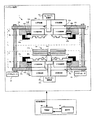
- FIG. 1 is a schematic diagram schematically showing a configuration of an imprint apparatus 1 which is an embodiment of a transfer apparatus of the present invention.
- the imprint apparatus 1 shown in FIG. 1 is a UV-type transfer apparatus that transfers a pattern on a mold to a transfer target having a transfer layer that is cured by UV irradiation. Further, the imprint apparatus 1 uses a lower mold 200a and an upper mold 200b on which a pattern such as a concavo-convex structure to be transferred is formed, and a lower transfer layer 301a and a lower transfer layer 301a formed on the lower surface of the substrate 300 that is a transfer target. In this configuration, transfer is performed on both of the upper transfer layer 301b formed on the upper surface.
- the imprint apparatus 1 includes a lower mechanism part A including a lower base 110a, an upper mechanism part B including an upper base 110b, and a lower base 110a. And a ball screw 101 that connects the upper base 110b, an actuator 104 that rotates the ball screw, a control unit 102 that controls the operation of the lower mechanism unit A and the upper mechanism unit B, and a user instruction to the control unit 102 An operation unit 103 that can be input is provided.
- the imprint apparatus 1 shown in FIG. 1 shows a state where the lower mold 200a, the upper mold 200b, and the substrate 300 are installed.
- the lower mold 200a is held on the lower mounting table 150a of the lower mechanism portion A so that the pattern surface faces upward.
- the upper mold 200b is held on the upper mounting table 150b of the upper mechanism B so that the pattern surface faces downward.
- the lower mold 200a and the upper mold 200b have a disk shape having a center hole at the center or a shape similar to a disk, and patterns such as irregularities are formed near the center hole on the pattern surface.
- a pattern region in which is formed is configured.
- At least a portion corresponding to the pattern region of each mold is made of a material that transmits UV light, such as quartz glass, and is preferably hardly affected by a change in character due to irradiation with UV light.
- a material that transmits UV light such as quartz glass
- the outside of the pattern area on the pattern surface is referred to as a non-pattern area.
- the pattern surface of the lower mold 200a and the upper mold 200b is subjected to a surface treatment for the purpose of improving mold releasability of the mold and the substrate at the time of mold release described later, for example, a surface treatment with a silane coupling agent or the like, A release layer having a thickness of a single molecule to several molecules is formed.
- the lower mold 200a is a specific example of the “mold” or “second mold” of the present invention
- the upper mold 200b is a specific example of the “mold” or “first mold” of the present invention. It is an example.
- the substrate 300 which is a transfer target has a UV curable lower transfer layer 301a and an upper transfer layer 301b on the upper surface and the lower surface, and the lower mold 200a and the upper mold 200b in the center.
- a disk-shaped configuration having a center hole with a diameter smaller than that of the center hole is used.
- the lower mechanism A is provided on the upper surface of the lower base 110a, and includes a lower center pin 120a, a lower UV irradiation unit 130a, a lower center pin driving unit 140a, a lower mounting table 150a, A side mold holding part 152a and a lower mold clamp 153a are provided.
- the lower base 110a is provided with a lower opening 111a and is connected to a lower mounting table 150a having a center hole at the center. Further, the lower base 110a is provided with a screw hole portion in which a screw groove is cut at a position where the ball screw 101 is screwed.
- the lower opening 111a is formed at a position corresponding to the center hole of the lower mounting table 150a, and includes a lower center pin 120a and a lower center pin driving unit 140a.
- the lower opening 111a typically has a lower UV irradiator 130a that can irradiate at least the region of the substrate 300 where the pattern of the lower transfer layer 301a is formed with UV light. It is formed wider than the region where the pattern is formed.
- the lower mounting table 150a is a circular member having a diameter larger than that of the substrate 300, and includes a lower mold holding part 152a and a lower mold clamp 153a.
- the lower mounting table 150a has a flat lower mold holding surface Sa for holding the lower mold 200a.
- the lower mold holding surface Sa is provided with a center hole at the center. .
- at least a portion corresponding to a region where the pattern of the lower mold 200a to be mounted transmits UV light such as quartz glass and is irradiated with UV light. It is made of a material that is unlikely to cause phenotypic changes, and is configured to be able to irradiate the lower transfer layer 301a with UV light emitted from the lower UV irradiator 130a.
- the lower mold holding part 152a is a specific example of the "mold holding means” or “second mold holding means” of the present invention in the lower mechanism part A, and holds the lower mold 200a by vacuum suction or the like.
- a suction portion 154a having a suction groove 155a and an elastic member 156a that supports the suction portion 154a.
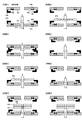
- FIG. 2B shows the lower mounting table 150a upward (more specifically, vertically upward with respect to the lower mold holding surface Sa.
- the vertical upper direction or simply upward will be described.
- It is a schematic diagram which shows arrangement
- the suction portion 154a is a groove formed in a corresponding region of the lower mold holding surface Sa so as to perform suction at the outer peripheral edge portion of the lower mold 200a to be placed. Placed inside.
- the suction portion 154a is preferably configured with, for example, a flexible resin member so as not to damage the lower mold 200a at the contact portion.
- the suction groove 155a is configured to be able to suck the lower mold 200a to the suction portion 154a by reducing the atmospheric pressure in the groove by the operation of a decompression mechanism (not shown) such as a connected vacuum pump.
- the elastic member 156a is disposed in a groove formed in the lower mold holding surface Sa and supports the suction portion 154a.
- the elastic member 156a is configured to be able to bias an elastic force between the adsorbing portion 154a and the lower mounting table 150a by a member having elasticity such as a resin or a mechanical structure such as a spring.
- a member having elasticity such as a resin or a mechanical structure such as a spring.
- the shape of the lower mold holding part 152a and the lower mounting table 150a is a shape suitable for deformation of the lower mold 200a described later, and such a shape will be described in detail later.
- the lower mold clamp 153a is a specific example constituting the “deformation means” or “second deformation means” of the present invention in the lower mechanism portion A, and is a pressing force based on a control signal supplied from the control unit 102.
- the lower mold 200a can be pressed vertically downward.
- a plurality of lower mold clamps 153a are typically arranged on the lower mounting table 150a, and the lower mold 200a can be elastically deformed by pressing a peripheral portion which is a non-pattern region of the lower mold 200a. Configured to be possible.
- the lower mold clamp 153a is configured to be able to hold and fix the lower mold 200a with the lower mounting table 150a.
- FIG. 2C is a diagram in which an arrangement position of an upper mold clamp 153b (described later) viewed from the same direction is superimposed on a configuration when the lower mold clamp 153a is viewed from vertically above the lower mold holding surface Sa. It is.
- the lower mold clamp 153a has a fan-like shape that is arranged concentrically with the lower mold 200a so that the lower mold 200a can be suitably gripped in accordance with the shape of the disk-shaped lower mold 200a. Yes.
- the upper mold clamp 153b has a sector shape that is concentrically arranged with the upper mold 200b so that the upper mold 200b can be suitably gripped in accordance with the shape of the disk-shaped upper mold 200b.
- the lower mold clamp 153a and the upper mold clamp 153b have three fan-shaped members arranged so as to be mutually inserted, and they are connected to the lower mold holding surface Sa. Are arranged so as not to overlap each other even when projected onto a plane parallel to the.
- the lower center pin 120a is a specific example constituting the “transfer object holding means” of the present invention, and is a cylindrical member having a tip portion 121a, a substrate support portion 122a, and a mold support portion 123a having different diameters.
- the lower end is connected to a lower center pin driving unit 140a, which will be described later, and the upper end passes through the center hole and the lower opening 111a of the lower mounting table 150a and is perpendicular to the lower mold holding surface Sa. It is supported to become.
- the diameter of the front end portion 121a of the lower center pin 120a is smaller than the diameter of the substrate support portion 122a and larger than the diameter of the center hole of the substrate 300 described later.
- the diameter of the substrate support part 122a is smaller than the diameter of the mold support part 123a and larger than the diameter of the center hole of the lower mold 200a described later.
- the diameter of the mold support portion 123a is smaller than the diameter of each of the center hole of the lower mounting table 150a and the lower opening 111a.
- the lower UV irradiation unit 130a is electrically connected to the control unit 102 via a signal line (not shown), and the lower transfer layer 301a of the substrate 300 is cured in accordance with a control signal supplied from the control unit 102.
- the UV light to be irradiated is irradiated to the lower transfer layer 301a of the substrate 300 through the lower opening 111a and the center hole of the lower mounting table 150a.
- the lower UV irradiation unit 130a may be configured to be retracted except when necessary, such as when UV light is irradiated in the transfer operation.
- the lower center pin drive unit 140a is a specific example that constitutes a part of the “transfer object holding unit” in the lower mechanism unit A of the present embodiment, and corresponds to a control signal supplied from the control unit 102.
- the lower center pin 120a is moved in the axial direction, that is, in a direction perpendicular to the lower mold holding surface Sa of the lower mounting table 150a.
- the lower center pin driver 140a moves the lower center pin 120a vertically upward when releasing the lower mold 200a and the substrate 300 after a transfer operation described later, thereby moving the substrate 300 to the lower mold 200a.
- release means or “second release means” in this embodiment.
- the upper mechanism B is provided on the lower surface of the upper base 110b, and includes an upper center pin 120b, an upper UV irradiation unit 130b, an upper center pin driving unit 140b, an upper mounting table 150b, an upper mold holding unit 152b, And an upper mold clamp 153b.
- An upper opening 111b is provided on the upper base 110b, and an upper mounting table 150b having a center hole at the center is connected to the upper base 110b.
- the upper base 110b is provided with a screw hole portion in which a screw groove is cut at a position where the ball screw 101 is screwed.
- the upper opening 111b is formed at a position corresponding to the center hole of the upper mounting table 150b, and includes an upper center pin 120b and an upper center pin driving unit 140b.
- the upper opening 111b typically has a pattern that allows the upper UV irradiator 130b to irradiate at least a region of the substrate 300 where the pattern of the upper transfer layer 301b is formed. It is formed wider than the region to be formed.
- the upper mounting table 150b is a circular member having a diameter larger than that of the substrate 300, and includes an upper mold holding part 152b and an upper mold clamp 153b.
- the upper mounting table 150b has a flat upper mold holding surface Sb for holding the upper mold 200b, and the upper mold holding surface Sb is provided with a center hole at the center. Note that at least a portion of the upper mounting table 150b corresponding to a region where the pattern of the upper mold 200b to be mounted is formed transmits UV light such as quartz glass and changes its characteristics by irradiation with UV light.
- the upper transfer layer 301b can be irradiated with UV light irradiated from the upper UV irradiation unit 130b.
- the upper mold holding part 152b is a specific example of the “mold holding means” or the “first mold holding means” of the present invention in the upper mechanism part B, and is a suction part for holding the upper mold 200b by vacuum suction or the like. 154b, an adsorption groove 155b, and an elastic member 156b. Unless otherwise specified, the configuration of the upper mold holding portion 152b, the suction portion 154b, the suction groove 155b, and the elastic member 156b are the same as the suction portion 154a of the lower mold holding portion 152a shown in FIG. The configuration is the same as that of the suction groove 155a and the elastic member 156a.
- the suction portion 154b is disposed in a groove formed in a corresponding region of the upper mold holding surface Sb so as to perform suction at the outer peripheral edge portion of the placed upper mold 200b.
- the adsorbing part 154b is preferably composed of a flexible resin member or the like so as not to damage the upper mold 200b at the contact part.
- the suction groove 155b is connected to decompression means such as a vacuum pump (not shown), and is configured to be able to suck and hold the upper mold 200b by lowering the atmospheric pressure in the groove by the operation of the decompression means.
- the elastic member 156a is disposed in a groove formed in the upper mold holding surface Sb and supports the suction portion 154b.
- the elastic member 156b is configured to be able to bias an elastic force between the adsorbing portion 154b and the upper mounting table 150b by a member having elasticity such as a resin or a mechanical structure such as a spring.
- a member having elasticity such as a resin or a mechanical structure such as a spring.
- the shape of the upper mold holding part 152b and the upper mounting table 150b is a shape suitable for deformation of the upper mold 200b described later, and such a shape will be described in detail later.
- the upper mold clamp 153b is a specific example that constitutes the “deformation means” or “first deformation means” of the present invention in the upper mechanism B, and the upper mold clamp 153b is moved upward by a pressing force based on a control signal supplied from the control unit 102. It is a member capable of pressing the mold 200b vertically upward.
- a plurality of upper mold clamps 153b are typically arranged on the upper mounting table 150b, and are configured to be capable of elastically deforming the upper mold 200b by pressing the peripheral portion of the upper mold 200b.
- the upper mold clamp 153b is configured to be able to hold and fix the upper mold 200b with the upper mounting table 150b.
- the upper center pin 120b is one specific example that constitutes the “transfer object holding unit” of the present invention, and is a cylindrical member having a tip portion 121b, a substrate support portion 122b, and a mold support portion 123b having different diameters.
- the upper end is connected to an upper center pin driving unit 140b, which will be described later, and the lower end passes through the center hole and the upper opening 111b of the upper mounting table 150b and is supported to be perpendicular to the upper mold holding surface Sb. ing.
- the diameter of the tip 121b of the upper center pin 120b is smaller than the diameter of the substrate support 122b and larger than the diameter of the center hole of the substrate 300 described later.
- the diameter of the substrate support part 122b is smaller than the diameter of the mold support part 123b and larger than the diameter of the center hole of the upper mold 200b described later.
- the diameter of the mold support portion 123b is smaller than the diameter of each of the center hole of the upper mounting table 150b and the upper opening 111b.
- the upper UV irradiation unit 130b is electrically connected to the control unit 102 via a signal line (not shown), and UV for curing the upper transfer layer 301b of the substrate 300 in accordance with a control signal supplied from the control unit 102. Light is applied to the upper transfer layer 301b of the substrate 300 through the upper opening 111b and the center hole of the upper mounting table 150b.
- the upper UV irradiation unit 130b may be retracted except when necessary, such as when UV light is irradiated in the transfer operation.
- the upper center pin driving unit 140b constitutes a part of a specific example of the “transfer object holding unit” of the present invention in the upper mechanism unit B, and the upper center pin driving unit 140b corresponds to a control signal supplied from the control unit 102. 120b is moved in the axial direction, that is, in a direction perpendicular to the upper mold holding surface Sb of the upper mounting table 150b.
- the upper center pin driving unit 140b presses the upper center pin 120b in the vertical downward direction when the upper mold 200b and the substrate 300 after the transfer operation described later are released, thereby causing the vertical position of the substrate 300 to move.
- release means or “first release means” in the present embodiment.
- the control unit 102 is an information processing apparatus such as a CPU (Central Processing Unit).
- the control unit 102 controls the position of each mold holding unit by supplying control signals to the lower mold clamp 153a of the lower mechanism unit A and the upper mold clamp 153b of the upper mechanism unit B, and holds the mold. Alternatively, the deformation of the mold is controlled.
- the control unit 102 responds to an input signal indicating a user instruction supplied from the operation unit 103, and includes a lower UV irradiation unit 130a, a lower center pin driving unit 140a, an upper UV irradiation unit 130b, and an upper center.
- a control signal for controlling the operation of each part of the pin driver 140b and the actuator 104 is supplied.
- the operation unit 103 includes a plurality of buttons or a keyboard that can be input by the user, and supplies a signal for instructing an operation in accordance with the input user instruction to the control unit 102.
- the control unit 102 reads an operation processing program stored therein to generate a control signal corresponding to the instruction and supply it to each unit.
- the actuator 104 is a mechanism such as a motor that can move the upper mounting table 150b toward or away from the lower mounting table 150a in accordance with a control signal supplied from the control unit 102. Specifically, the actuator 104 rotates the ball screw 101 in accordance with a control signal supplied from the control unit 102, so that the upper base 110 b engaged with the ball screw 101 is moved to the upper mold holding surface Sb and the lower mold. It moves in the vertical direction with respect to the upper mold holding surface Sb while maintaining the parallel positional relationship with the holding surface Sa. According to such an operation of the actuator 104, the upper base 110b moves vertically upward, so that the upper base 150b is separated from the lower base 150a in a direction perpendicular to the upper mold holding surface Sb. To move.
- the upper base 110b moves vertically downward
- the upper stage 150b moves so as to be close to the lower mounting table 150a in a direction perpendicular to the upper mold holding surface Sb.
- four ball screws 101 are provided so as to connect the four corners of the lower base 110a and the upper base 110b, and a plurality of actuators 104 are also provided to rotate the corresponding ball screws 101.
- the actuator 140 moves the upper mounting table 150b vertically downward in a transfer operation described later, thereby pressing the upper mold 200b and the substrate 300 to each other, and further pressing the lower mold 200a and the substrate 300 to each other.
- the actuator 104 constitutes a specific example of “pressing means” or “first pressing means” and “second pressing means” in the present embodiment.
- the actuator 104 moves the upper mold table 150b vertically upward while holding the upper mold 200b when the upper mold 200b and the substrate 300 after the transfer operation described later are released.
- This is a structure for releasing from the substrate 300, and constitutes a specific example of “release means” or “first release means” in the present embodiment.
- FIG. 3 is a schematic transmission diagram when the lower base 110a, the lower mechanism A, and the surrounding configuration are viewed from the vertically upward direction. Note that FIG. 3 does not show the lower mold holding portion 152a and the lower mold clamp 153a provided on the lower mounting table 150a.
- the actuator 104 is connected to each of the pole screws 101 arranged at the four corners of the lower base 110a, and the pole screws are rotated based on a control signal from the control unit 102.
- the upper base 110b and the upper mechanism B are also configured in the same manner as the lower base 110a and the lower mechanism A, and are vertically upward from the lower base 110a at the four corners of the square upper base 110b.
- Four pole screws 101 extending in the direction are screwed together.
- FIGS. 4A to 4E are schematic views showing the structures of the lower mounting table 150a and the lower mold holding part 152a in plan, respectively.
- the structures of the upper mounting table 150b, the upper mold holding portion 152b, and the upper mold clamp 153b are the same as those on the lower side.
- the outer diameter of the suction part 154a constituting the mold holding part 152a is larger than the outer diameter of the lower mold 200a, and the outer diameter of the suction groove 155a is smaller than that of the lower mold 200a. Smaller than outer diameter.
- the top of the suction portion 154a supported by the elastic member 156a is vertically downward (hereinafter referred to as a vertical downward direction) with respect to the lower mold holding surface Sa from the lower mold holding surface Sa in the lower mounting table 150a. It is formed in a concave shape, and the depth of the concave portion is an appropriate depth that does not interfere with the mounting of the lower mold 200a. For example, the mold is not deformed, and the mold is sufficiently adsorbed when vacuum suction is activated. It is set within the possible 10 micrometers. In order to realize the depth set in this manner with high accuracy, the elastic member 156a is adjusted by a stripper bolt, a shim, or the like. Further, the elastic member 156a preferably has a structure in which galling is unlikely to occur on the contact surface with the lower mounting table 150a. A combination of the above and a retainer structure are adopted.
- the lower mold 200a is adsorbed by the negative pressure in the adsorption groove 155a and vertically lowered by the lower mold clamp 153a as shown in FIG. 4B. It is gripped by being pressed in the direction.
- the lower mold clamp 153a increases the pressing force for pressing the lower mold 200a vertically downward when instructed by the control signal supplied from the control unit 102 to deform the lower mold 200a.
- the lower mold 200a With such a pressing force, the lower mold 200a is bent so as to incline from the central portion toward the peripheral portion, and the peripheral portion is strongly pressed against the suction portion 154a.
- the elastic member 156a that holds the suction portion 154a contracts, thereby serving as a cushion against the pressing force of the lower clamp mold.
- the elastic force and size of the elastic member 156a are adjusted so that the pressing force of the lower clamp mold and the elastic force are balanced at a position where a predetermined amount of mold deformation is realized. For this reason, the lower mold 200a is not deformed beyond the set amount of deformation of the mold, and the breakage of the mold can be suitably suppressed.
- the deformation operation of the lower mold 200a is performed.
- the lower mold clamp 153a has at least a pressing force for gripping the lower mold 200a and a pressing force stronger than the pressing force for gripping the lower mold 200a.
- the lower mold 200a can be pressed with two kinds of forces.
- the lower mold clamp 153a presses the lower mold 200a with the above-described at least two types of pressing forces in accordance with a control signal supplied from the control unit 102.
- the lower mold clamp 153a presses the lower mold 200a with a gripping force that is a pressing force for gripping according to a gripping control signal, and with a deformation force that is a pressing force for deformation according to a deformation control signal.
- the lower mold 200a is pressed.
- the upper mold clamp 153b presses the upper mold 200b with a gripping force that is a pressing force for gripping according to the gripping control signal, and the upper mold clamp 153b with a deformation force that is a pressing force for deformation according to the deformation control signal.
- the mold 200b is pressed.
- the structures of the lower mounting table 150a and the lower mold holding portion 152a are not limited to the structure shown in FIG. 4A, and may be any structure as long as the above-described deformation operation can be performed. Absent.
- the substrate 300 is approximately 100 micrometers from the outer diameter toward the peripheral portion from the outer peripheral portion, and vertically downward from the other portions.
- a step structure having a predetermined depth may be used. The depth of the step structure may be arbitrarily set according to the deformation amount of the lower mold 200a. For example, the maximum deformation amount due to the bending of the lower mold 200a having a size of 4 inches and a thickness of 1 mm is 200.
- the depth of the step structure is set to about 100 micrometers.
- the shape of the step structure may be any shape as long as the deformation of the lower mold 200a is not hindered, and may be, for example, an inclined or curved surface structure.
- suction part 154a is higher than the lower side of a level
- the lower mounting table 150a may be formed of different members at the position where the elastic member 156a and the suction portion 154a are arranged.
- the hatched portion on the inner peripheral side from the elastic member 156a and the suction portion 154a is formed of a transparent material such as quartz glass, and the plain portion on the outer peripheral side is formed of a metal material or the like. It is good also as a structure which combines both. With such a structure, the shape processing of the lower mounting table 150a becomes easier, which is effective in terms of cost reduction in the apparatus configuration.
- Each of the upper mounting table 150b and the upper mold holding unit 152b may have a structure according to the structure of the lower mounting table 150a and the lower mold holding unit 152a.
- the lower mold clamp 153a of the lower mechanism portion A is pressed with a pressing force that is weaker than the pressing force for elastically deforming the lower mold 200a.
- the holding of the lower mold 200a may be realized by sandwiching it with the mounting table 150a.
- the upper mechanism B may have the same configuration.
- the lower mold 152a placed on the lower placement table 150a is pressed vertically downward by the lower mold clamp 153a, thereby lowering the lower mold 152a.
- Deformation is realized.
- the elastic deformation of the lower mold 200a may be realized by moving the suction portion 154a that is sucked to the lower mold 200a. Specifically, even if the suction part 154a is attracted to the peripheral part of the lower mold 200a, a mechanism for moving the suction part 154a vertically downward is provided in the lower mold holding part 152a. Good.
- the suction portion 154a moves vertically downward, whereby the peripheral portion of the lower mold 200a is drawn vertically downward, and elastic deformation occurs in the lower mold 200a.
- the upper mechanism B may have the same configuration.
- the lower mold 200a is moved in the vertical direction relative to the suction portion 154a.
- the elastic deformation may be realized.
- a vertical position difference is generated between the suction portion 154a that is attracted to the peripheral portion of the lower mold 200a and the lower mold holding surface Sa of the lower mounting table 150a that is in contact with the lower surface of the lower mold 200a.
- achieve the elastic deformation of the lower mold 200a mentioned above by means, such as, may be provided.
- FIG. 5 is a flowchart showing a series of transfer operations performed by the imprint apparatus 1
- FIGS. 6 and 7 are diagrams schematically showing the operation of each part of the imprint apparatus 1 in each process during the transfer operation. is there.
- the operation flow of each process shown in the flowchart of FIG. 5 will be described with reference to the operation of the imprint apparatus 1 shown in FIGS. 6 and 7.
- the upper mold 200b is attached to the initial imprint apparatus 1 (FIG. 6 [state 1]) in which none of the upper mold 200b, the lower mold 200a, and the substrate 300 is installed.
- Step S101 More specifically, in step S101, first, the upper mold 200b is moved by the operation of a mold conveying device (not shown) so that the front end portion 121a of the lower center pin 120a penetrates the center hole, and the lower center pin 120a.
- the control unit 102 operates the actuator 104 so that the upper mold holding surface Sb of the upper mounting table 150b is in contact with the upper surface of the upper mold 200b (that is, the back surface of the surface on which the pattern is formed).
- the mounting table 150b is moved vertically downward.
- the control unit 102 operates a decompression unit (not shown) to adsorb and hold the upper mold 200b on the adsorption unit 154b of the upper mounting table 150b.
- a grip control signal is transmitted to the upper mold clamp 153b, and the upper mold 200b is pressed vertically upward to be fixed to the upper mounting table 150b (FIG. 6 [State 3]).
- the control unit 102 operates the actuator 104 to move the upper mounting table 150b to the initial position in the vertical upward direction (FIG. 6 [state 4]).
- step S102 the lower mold pin 200a is formed so that the tip 121a of the lower center pin 120a penetrates the center hole by an operation of a mold conveying device (not shown). It is installed on the mold support part 123a of 120a (FIG. 6 [state 5]).
- the control unit 102 operates the lower center pin driving unit 140a so that the lower mold holding surface Sa of the lower mounting table 150a is the lower surface of the lower mold 200a (that is, the back surface of the surface on which the pattern is formed). ), The lower center pin 120a is moved vertically downward.
- the control unit 102 operates a decompression unit (not shown) to adsorb the upper mold 200a to the adsorption unit 154a of the lower mounting table 150a and hold it.
- a grip control signal is transmitted to the lower mold clamp 153a, and the lower mold 200a is pressed vertically downward to be fixed to the lower mounting table 150a (FIG. 6 [State 6]).
- FIG. 8 is an example of a graph showing temporal changes in the pressing force acting on each of the upper mold clamp 153b and the lower mold clamp 153a in a series of flows of the transfer operation of the present embodiment.
- FIG. 8A shows a temporal change in the pressing force of the upper mold clamp 153b
- FIG. 8B shows a temporal change in the pressing force of the lower mold clamp 153a.
- the pressing force of the upper mold clamp 153b is gradually increased by supplying the grip control signal.
- the lower mold clamp 153a The pressing force gradually increases, and the lower mold 200a is gripped with a desired gripping force.
- the substrate 300 is placed on the substrate support portion 122a of the lower center pin 120a in such a manner that the tip portion 121a of the lower center pin 120a penetrates the center hole by the operation of a substrate transfer device (not shown).
- a substrate transfer device not shown.
- the control unit 102 may align the lower mold 200a and the upper mold 200b with the substrate 300 as necessary.
- the control unit 102 transmits a deformation control signal to the lower mold clamp 153a and the upper mold clamp 153b to cause the lower mold 200a and the upper mold 200b to be deformed (Step S104, FIG. 6 [State 8] ]).
- the upper mold clamp 153b that has received the deformation control signal deforms the upper mold 200b by pressing it with a deformation force, while the lower mold clamp 153a presses the lower mold 200a with a deformation force.
- the lower mold 200a is deformed.
- the pressing force of each mold clamp is controlled so as to gradually increase from the gripping force to the deformation force, as shown in FIGS. 8 (a) and 8 (b).
- control unit 102 is supported by operating the lower center pin driving unit 140a to move the lower center pin 120a vertically downward while maintaining the deformed state of the lower mold 200a and the upper mold 200b.
- the lower transfer layer 301a of the substrate 300 is brought into contact with the pattern surface of the lower mold 200a (FIG. 7 [State 9]).
- control unit 102 operates the lower center pin driving unit 140a to move the lower center pin 120a vertically downward, and the pattern of the lower transfer layer 301a and the lower mold 200a to be supported is supported. The surface is brought into contact (step S105, FIG. 7 [state 9]). Further, the control unit 102 operates the actuator 104 to move the upper mounting table 150b vertically downward to bring the pattern surface of the upper mold 200b into contact with the upper transfer layer 301b of the substrate 300 (FIG. 7 [state] 10]).
- each mold and the contact with the substrate 300 may be performed in the above-described order. Also, the deformation of the lower mold 200a, the contact between the lower mold 200a and the substrate 300, the deformation of the upper mold 200b, You may perform from one side in the order of contact with the upper mold 200b and the board
- the control unit 102 transmits a control signal to the lower mold clamp 153a and the upper mold clamp 153b to release the deformation of the lower mold 200a and the upper mold 200b (step S106). ).
- the controller 102 changes the pressing force of the upper mold clamp 153b and the lower mold clamp 153a from the deformation force to the gripping force as shown in FIGS. 8 (a) and 8 (b).
- a grip control signal is transmitted so as to gradually decrease.
- the grip control signal that gradually decreases from the deformation force to the grip force may be synchronized with the lower center pin drive unit 140a and the actuator 104 that are operated to bring each mold into contact with the substrate 300.
- the control unit 102 A grip control signal for releasing the deformation of the mold may not be transmitted.
- the control unit 102 operates the actuator 104 to move the upper mounting table 150b vertically downward, and the upper mold 200b is placed on the upper transfer layer 301b on the upper surface of the substrate 300, and the lower mold 200a is moved.
- the lower transfer layer 301a of the lower surface of the substrate 300 is pressed with a predetermined pressing force (Step S107, FIG. 7 [State 11]).
- the control unit 102 emits UV light from the lower UV irradiation unit 130a and the upper UV irradiation unit 130b in order to cure the lower transfer layer 301a and the upper transfer layer 301b of the substrate 300 while maintaining the pressed state.
- the lower transfer layer 301a and the upper transfer layer 301b of the substrate 300 are cured in accordance with the pattern formed on the surface of each mold, and the pattern is transferred (step S108).
- the pressure and pressing time during pressing, and the intensity and irradiation time of UV irradiation are preferably set as appropriate according to the size and shape of the transfer pattern, the characteristics of the transfer layer, and the like.
- a mold release operation is performed to release the lower mold 200a and the substrate 300 and the upper mold 200b and the substrate 300 which are in close contact with each other. Is called.
- control unit 102 In the mold release operation, the control unit 102 first stops the operation of the actuator 104 that presses the upper mounting table 150b, and releases the pressing state between each mold and the substrate 300. At the same time or before and after, the control unit 102 operates the upper center pin driving unit 140b so that the tip of the upper center pin presses the substrate 300 vertically downward at a predetermined pressure (step S109, FIG. S2 [ State 12]).
- the substrate 300 is sandwiched between the lower center pin 120a and the upper center pin 120b.
- the control unit 102 controls the lower center pin driving unit 140a and the upper center so that excessive pressure is not applied to the substrate 300 held between the lower center pin 120a and the upper center pin 120b.
- drive control such as torque control is performed on at least one of the pin drive units 140b.
- control unit 102 performs deformation of the lower mold 200a and the upper mold 200b by the same operation as the above-described step S104 (step S110, FIG. 7 [state 13]). At this time, the pressing force of each mold clamp is controlled to gradually increase from the gripping force to the deformation force.
- the control unit 102 operates the upper center pin 120b and the actuator 104 to move the upper mounting table 150b to the initial position in the vertical upward direction.
- the upper mold 200b moves vertically upward while being held by the upper mounting table 150b, while the substrate 300 is pressed vertically downward (in other words, fixed) by the upper center pin 120b. Therefore, the upper mold 200b and the upper transfer layer 301b of the substrate 300 are released (Step S111, FIG. 7 [State 14]).
- control unit 102 moves the lower center pin 120a supporting the substrate 300 to the initial position in the vertical upward direction, and releases the lower mold 200a and the substrate 300 (Step S112, FIG. 7 [State 15 ]).
- control unit 102 changes the pressing force of the upper mold clamp 153b and the lower mold clamp 153a to a gripping force for gripping the mold, and releases the deformation of the lower mold 200a and the upper mold 200b. (Step S113, FIG. 7 [State 16]).
- step S114 The substrate 300 released from the lower mold 200a and the upper mold 200b is removed from the lower center pin 120a by an operation of a substrate transfer device (not shown) (step S114).
- step S115: No when performing transfer using the same lower mold 200a and upper mold 200b for another substrate 300 (step S115: No), the steps from step S103 to step S114 for placing the substrate 300 are performed. Run repeatedly. After all the transfer is completed (step S115: Yes), the lower mold 200a is first removed (step S116) and then the upper mold 200b is removed (step S117) by the operation of a mold conveyance device (not shown). .
- the lower mold 200a and the upper mold 200b are moved relative to the transfer surface 301a and the upper transfer layer 301b of the substrate 300.
- the pattern formed on the surface is transferred.
- each of the lower mold 200a and the upper mold 200b is brought into contact with the substrate 300 in a state where the bending occurs.
- the for this reason particularly as shown in FIG. 7 [State 10], in each of the lower mold 200a and the upper mold 200b, bending occurs so as to sequentially contact the substrate 300 from the central portion toward the peripheral portion.
- the holes mixed in the contact portion are pushed out to the peripheral edge as the contact proceeds, and are removed from the contact surface.
- the transfer pattern on the substrate obtained by the transfer operation is not possible for the pattern of the portion where the holes are generated. Deficiency may occur.
- the lower transfer layer 301a and the upper transfer layer 301b provided on the substrate 300 may be made of a material having fluidity, which is particularly effective when such a material is used. This is beneficial in the operation of the nanoimprint transfer apparatus, which is expected to process a large amount of transferred material by continuous transfer.
- a mold release starting point is formed between the mold and the transfer layer. Is done. Specifically, in the case of the lower mold 200a, the peripheral portion bends in the vertical downward direction by a predetermined amount of deformation, so that the lower mold 200a and the lower transfer layer 301a are peeled off by a minute amount. The point peeled in this way becomes the mold release start point, and the peel state can be advanced with a weaker force than the case where the mold release start point does not exist from the peripheral part of the lower mold 200a toward the center part. It becomes possible.
- the mold and the substrate can be released with a weaker force than when the release start point does not exist, and the contact surface between the mold and the substrate transfer layer is released. It is possible to suitably suppress the occurrence of damage to the pattern formed on the mold, the substrate itself, or both due to the concentration of the force, and the pattern can be transferred accurately.
- the amount of deformation of the mold is determined by the shapes of the lower mounting table 150a and the lower mold holding unit 152a, the upper mounting table 150b and the upper mold holding unit 152b shown in each drawing of FIG. 4, and the lower mold clamp 153a. And it becomes possible to set appropriately according to the pressing force of the upper mold clamp 153b. For this reason, when aligning the mold and the substrate, the alignment mark formed on the mold is not distorted, and the mold and the substrate can be aligned with high accuracy, and a fine pattern can be accurately transferred. Is feasible. In addition, it is possible to relatively easily set the optimal deformation amount according to the material and thickness of the mold and the substrate and the transfer conditions for enjoying the above-described effects more remarkably.
- the imprint apparatus 1 it is possible to realize the deformation of the mold without additionally using a dedicated actuator for deforming the mold or a structure for deforming the mold with a negative pressure. For this reason, it is possible to realize an apparatus configuration capable of enjoying the above-described effects with an inexpensive and relatively simple configuration. This is also advantageous in that maintenance for maintenance of the apparatus can be easily performed.
- FIG. 9 is a schematic diagram schematically showing a configuration of an imprint apparatus 1 ′ which is a modification of the transfer apparatus of the present invention. Note that, in this modification and FIG. 9, the same components as those of the imprint apparatus 1 shown in FIG.
- the imprint apparatus 1 ′ shown in FIG. 9 is a UV-type transfer apparatus that transfers the pattern on the surface of the lower mold 200 a to the substrate 300 including the lower transfer layer 301 a that is cured by UV irradiation.
- the imprint apparatus 1 ′ includes a lower mechanism A configured on the lower base 110a, an upper base 110b, and a ball screw 101 that connects the lower base 110a and the upper base 110b.
- the control unit 102 controls the operation of the lower mechanism unit A, and the operation unit 103 can input a user instruction to the control unit 102.
- the imprint apparatus 1 ′ shown in FIG. 9 shows a state where the lower mold 200 a and the substrate 300 are installed.
- the lower mold 200a is held on the lower mounting table 150a of the lower mechanism portion A so that the surface on which the pattern is formed faces upward.
- the actuator 104 rotates the ball screw 101 under the control of the control unit 102, whereby the upper base 110b, the upper mold holding surface Sb of the upper mounting table 150b, and the lower mounting table are rotated.
- 150a is moved in a direction perpendicular to the upper mold holding surface Sb while maintaining parallel to the lower mold holding surface Sa.
- the upper base 110b moves vertically upward, so that the upper base 150b is separated from the lower base 150a in a direction perpendicular to the upper mold holding surface Sb.
- the upper base 110b moves vertically downward, so that the upper stage 150b moves closer to the lower stage 150a in the direction perpendicular to the upper mold holding surface Sb.
- the imprint apparatus 1 ′ which is a modification of the transfer apparatus according to the present invention described above, has various effects similar to those of the imprint apparatus 1 described above, while being lower than the lower transfer layer 301 a of the substrate 300. A pattern formed on the surface of the mold 200a can be transferred.
- the substrate 300 is deformed using a configuration similar to that of a mold clamp or the like, and the lower mold 200a is contacted and released while the deformation is maintained. There may be. Even in such a configuration, the pattern formed on the surface of the lower mold 200a can be transferred to the lower transfer layer 301a of the substrate 300 while enjoying various effects similar to those of the imprint apparatus 1 described above. .
- FIG. 10 is a schematic diagram schematically showing the configuration of an imprint apparatus 1 ′′ and a control apparatus 400, which are a second modification of the transfer apparatus of the present invention. Note that, in this modification and FIG. 10, the same components as those of the imprint apparatus 1 shown in FIG.
- the imprint apparatus 1 '' is a configuration that does not include the control unit 102 and the operation unit 103 in the imprint apparatus 1 shown in FIG. Other parts may be equivalent to the imprint apparatus 1.
- the control device 400 includes a control unit 102 ′ and an operation unit 103 ′ having the same configuration as the control unit 102 and the operation unit 103 of the imprint apparatus 1, and is electrically connected to each unit of the imprint apparatus 1 ′′. Is done. In this configuration, the control unit 102 ′ of the control device 400 controls the operation by supplying a control signal to each unit of the imprint apparatus 1 ′′.
- the imprinting device 1 ′′ and the control device 400 are arranged at separate positions, and the same effect as that obtained by the imprinting device 1 described above is obtained. You can enjoy it.
- one control device 400 is connected to a plurality of imprint devices and controls the operation of each imprint device.
- one control device 400 is provided for n imprint devices 1 ′′ -1, 2,...
- the operation of each imprint apparatus is controlled by supplying control signals to the imprint apparatuses 1 ′′ -1, 2,... N.
- one control device 400 supplies control signals to a plurality of n imprint devices 1 ′′ -1, 2,... N, and the like, as shown in FIGS. Centralized control is performed so that each process related to the transfer operation is performed.
- a fourth modified example there is an apparatus configuration in which a user's instruction for controlling operations is input by a single operation unit to a plurality of control units respectively connected to a plurality of imprint apparatuses. is there.
- the individual control units 102′-1, 2,. are connected to control the operation of each imprint apparatus 1 ′′ -1, 2,... N.
- the operation unit 103 ′ is connected to each of the control units 102′-1, 2,... N, and inputs an instruction by a user operation.
- the user concentrates settings such as operation start, operation stop, and the number of substrates to be transferred in each imprint apparatus 1 ′′ -1, 2,... N by using one operation unit 103 ′.
- the operation unit 103 ′ inputs the set instruction content to the control units 102′-1, 2,... N of the imprint apparatuses 1 ′′ -1, 2,.
- control units 102′-1, 2,... N of the respective imprint apparatuses 1 ′′ -1, 2,... N respectively correspond to the corresponding imprint apparatuses 1 ′′ -1, 2,.
- a control signal is supplied so that n performs each step related to the transfer operation shown in FIGS.
- one control device 400 or operation unit 103 ′ is used for each of the plurality of imprint devices 1 ′′ -1, 2,.
- User instructions can be input. For this reason, centralized management is possible in a factory where many imprint apparatuses are required to operate simultaneously. Moreover, it is useful also in terms of apparatus configuration and cost.
- the UV type imprint apparatus has been described as an example.
- 1 imprint device 101 ball screw, 102 actuator, 103 control unit, 104 operation unit, 110a Lower base, 110b upper base, 120a Lower center pin, 120b upper center pin, 130a Lower UV irradiation part, 130b Upper UV irradiation part, 140a Lower center pin drive unit, 140b upper center pin drive unit, 150a Lower mounting table, 150b upper mounting table, 151a lower opening, 151b upper opening, 152a Lower mold holding part, 152b Upper mold holding part, 153a Lower mold clamp, 153b Upper mold clamp, 154a Lower suction part, 154b upper suction part, 155a Lower suction groove, 155b upper suction groove, 156a lower elastic member, 156b upper elastic member, 200a lower mold, 200b Upper mold, 300 substrates, 301a Lower transfer layer, 301b Upper transfer layer.
Landscapes
- Engineering & Computer Science (AREA)
- Mechanical Engineering (AREA)
- Shaping Of Tube Ends By Bending Or Straightening (AREA)
Abstract
本発明の転写装置(1)は、モールド(200)に形成されたパターンを被転写体(300)に転写する転写装置であって、モールドが保持されるモールド保持手段(154a)と、被転写体を保持する被転写体保持手段(120a、120b)と、モールド及び被転写体を接触させて相互に押圧する押圧手段(104)と、密着させたモールド及び被転写体を離型させる離型手段(104、140a、140b)と、モールドと被転写体とが相互に押圧される直前の接触時、及び押圧後の離型時の少なくとも一方においてモールドを変形させる変形手段(153a)とを備える。一方で、変形手段は、モールドと被転写体とが相互に押圧される間、保持のために、モールド保持手段に対してモールドを取り付ける間、及びモールド保持手段に保持されるモールドを取り外す間はモールドを変形させない。
Description
本発明は、凹凸パターンが形成されたモールドを被転写体に押圧することで被転写体に凹凸パターンを転写する転写装置及び方法、並びにコンピュータプログラムの技術分野に関する。
この種の転写装置では、モールドが保持される保持部材と、被転写体が保持される保持部材とが互いに接近するように移動されることでモールドと被転写体とを密着及び押圧し、その後、密着させたモールドと被転写体を分離する(所謂、離型動作)ことで、モールド表面に形成されたパターンなどが被転写体表面に転写される。このとき、モールドと被転写体は平行に接近して平行に密着し、平行に離型する。このため、モールドの面積が大きいほど、モールドと被転写体の間に気泡の巻き込みが多くなり、転写されるパターンの精度が悪化してしまうという技術的な問題が生じる。このような技術的な問題の対策のために、例えば、真空減圧機能などによって気泡の巻き込みを抑制する構成などが求められることがある。また、密着させたモールドと被転写体との間の密着力が強い場合、離型動作において、密着面に大きな力が作用してしまい、モールドや被転写体自体、又は、両者に形成したパターンに損傷などが生じかねないとの技術的な問題が指摘されている。
かかる技術的な問題に対して、例えば、特許文献1には、予め傾斜が形成された保持部材にモールドを固定することで、モールドに曲げ変形を施す装置構成が開示されており、特許文献2には、モールドに空気圧を利用して湾曲させる手段を備える装置構成が開示されている。また、密着させたモールドと被転写体を分離する装置として、特許文献3には、チャンバー内を負圧にすることでモールドを撓ませる剥離装置の構成が開示されている。
しかしながら、上述した特許文献に開示される構成を用いるだけでは、インプリント転写装置における精確なパターン転写を達成する上で必ずしも有効とは言えない点もある。例えば、上述の文献に記載の構成では、安定したモールドの変形及びその変形量を得るためには、モールドの材質や厚み又はこれらの組合せが重要となるため、使用可能なモールドが限定されてしまうといった技術的な問題がある。
本発明は、上述した技術的な問題に鑑みて為されたものであり、典型的には、ナノインプリント転写装置において、モールドの変形をより好適に実施することで、モールドや被転写体、又はモールドに形成されるパターンや被転写体に転写されたパターンに損傷などが生じることを好適に抑制し、パターンの転写を精確に実施可能な転写装置及び方法、並びにコンピュータプログラムを提供することを課題とする。
上記課題を解決するために、本発明の第1の転写装置は、モールドに形成されたパターンを被転写体に転写する転写装置であって、前記モールドが保持されるモールド保持手段と、前記被転写体を保持する被転写体保持手段と、前記モールド及び前記被転写体を接触させて相互に押圧する押圧手段と、密着させた前記モールド及び前記被転写体を離型させる離型手段と、前記モールドと前記被転写体とが相互に押圧される直前の接触時、及び押圧後の離型時の少なくとも一方において、前記モールド保持手段を移動させて前記モールドを変形させる変形手段とを備える。
上記課題を解決するために、本発明の第2の転写装置は、第1モールドに形成されたパターンを被転写体の第1の面に転写し、且つ第2モールドに形成される前記パターンを前記被転写体の第2の面に転写する転写装置であって、前記第1モールドが保持される第1モールド保持手段と、前記第2モールドが保持される第2モールド保持手段と、前記被転写体を保持する被転写体保持手段と、前記第1モールド及び前記被転写体を接触させて相互に押圧する第1押圧手段と、前記第2モールド及び前記被転写体を接触させて相互に押圧する第2押圧手段と、前記第1モールドと前記被転写体との離型を行なう第1離型手段と、前記第2モールドと前記被転写体との離型を行なう第2離型手段と、前記第1モールドと前記被転写体とが相互に押圧される直前の接触時、及び押圧後の離型時の少なくとも一方において、前記第1モールド保持手段を移動させて前記第1モールドを変形させる第1変形手段と、前記第2モールドと前記被転写体とが相互に押圧される直前の接触時、及び押圧後の離型時の少なくとも一方において、前記第2モールド保持手段を移動させて前記第2モールドを変形させる第2変形手段とを備える。
上記課題を解決するために、本発明の第3の転写装置は、制制御装置からの指示に応じて動作し、モールドに形成されたパターンを被転写体に転写する転写装置であって、前記制御装置の指示に応じて、前記モールドが保持されるモールド保持手段と、前記制御装置の指示に応じて、前記被転写体を保持する被転写体保持手段と、前記制御装置の指示に応じて、前記モールド及び前記被転写体を接触させて相互に押圧する押圧手段と、前記制御装置の指示に応じて、密着させた前記モールド及び前記被転写体を離型させる離型手段と、前記制御装置の指示に応じて、前記モールドと前記被転写体とが相互に押圧される直前の接触時、及び押圧後の離型時の少なくとも一方において、前記モールド保持手段を移動させて前記モールドを変形させる変形手段とを備える。
上記課題を解決するために、本発明の第1の転写方法は、モールドに形成されたパターンを被転写体に転写する転写装置における転写方法であって、前記モールドを保持するモールド保持工程と、前記被転写体を保持する被転写体保持工程と、前記モールド及び前記被転写体を接触させて相互に押圧する押圧工程と、密着する前記モールド及び前記被転写体を離型させる離型工程と、前記押圧工程及び前記離型工程の少なくとも一方において、前記モールドが保持される部材を移動させて前記モールドを変形する変形工程とを備える。
上記課題を解決するために、本発明の第2の転写方法は、第1モールドに形成されたパターンを被転写体の第1の面に転写し、且つ第2モールドに形成される前記パターンを前記被転写体の第2の面に転写する転写装置における転写方法であって、前記第1モールドを保持する第1モールド保持工程と、前記第2モールドを保持する第2モールド保持工程と、前記被転写体を保持する被転写体保持工程と、前記第1モールド及び前記被転写体を接触させて相互に押圧する第1押圧工程と、前記第2モールド及び前記被転写体を接触させて相互に押圧する第2押圧工程と、前記第1モールドと前記被転写体との離型を行なう第1離型工程と、前記第2モールドと前記被転写体との離型を行なう第2離型工程と、前記第1押圧工程及び前記第1離型工程の少なくとも一方において、前記第1モールドが保持される部材を移動させて前記第1モールドを変形する第1変形工程と、前記第2押圧工程及び前記第2離型工程の少なくとも一方において、前記第2モールドが保持される部材を移動させて前記第2モールドを変形する第2変形工程とを備える。
上記課題を解決するために、本発明のコンピュータプログラムは、モールドに形成されたパターンを被転写体に転写する転写装置を動作させるためのコンピュータプログラムであって、前記モールドを保持するモールド保持工程と、前記被転写体を保持する被転写体保持工程と、前記モールド及び前記被転写体を接触させて相互に押圧する押圧工程と、密着させた前記モールド及び前記被転写体を離型させる離型工程と前記押圧工程及び前記離型工程の少なくとも一方において、前記モールドが保持される部材を移動させて前記モールドを変形する変形工程とを前記転写装置に実行させる。
本発明の作用及び他の利得について、以下に示す実施の形態とともに説明する。
本発明の転写装置に係る第1実施形態は、モールドに形成されたパターンを被転写体に転写する転写装置であって、前記モールドが保持されるモールド保持手段と、前記被転写体を保持する被転写体保持手段と、前記モールド及び前記被転写体を接触させて相互に押圧する押圧手段と、密着させた前記モールド及び前記被転写体を離型させる離型手段と、前記モールドと前記被転写体とが相互に押圧される直前の接触時、及び押圧後の離型時の少なくとも一方において、前記モールド保持手段を移動させて前記モールドを変形させる変形手段とを備える。
本発明の転写装置に係る第1実施形態によれば、モールド保持手段が保持するモールドが、被転写体保持手段に保持される被転写体に押圧されることにより、モールドに形成された凹凸などのパターンが被転写体に転写される。
モールド保持手段には、モールドが載置され、例えば後に詳述する真空ポンプなどを備える吸着機構を備えている。
被転写体保持手段は、モールドとの密着の妨げとならないよう、被転写体を保持し、且つ固定可能に構成される部材である。例えば、被転写体保持手段は、被転写体を2つの相対する方向から狭持することで保持を行なう構成などであってよい。
押圧手段は、上述したような保持がされているモールド及び被転写体の一方または両方を移動させて、モールドのパターンが形成された面(以下、パターン面と称して説明する)と被転写体のパターンが転写される面(以下、転写面と称して説明する)とを密着させ、更に相互に押圧可能な構成である。押圧手段は、例えば、モールド保持手段又は被転写体保持手段を移動させて、上述の押圧を実現させるアクチュエータなどである。また、押圧手段の構成及び動作については、公知の転写装置に備えられる押圧手段と同様のものであってもよい。
離型手段は、密着状態にあるモールドと被転写体とを離型させる構成である。例えば離型手段は、モールド保持手段及び被転写体保持手段の一方を固定して、他方に対して分離させる方向に力(以下、離型力と称して説明する)を作用させることで、離型を実現する。
変形手段は、モールド保持手段を移動させるとともに、モールドに対して変形を生じさせる動作を行う構成である。ここに「モールドの変形」とは、典型的には、被転写体の転写面と相対面して保持されるモールドのパターン面の少なくとも一部が、該転写面に対して所定の角度を有して傾斜する変形を示す。より汎用には、モールドのパターン面の一部が被転写体の転写面に面していると同時に、他部が被転写体の転写面に面していない状態を呈するものであり、モールドにおける、パターン面と交差する断面の形状或いは3次元的な外観形状が、典型的には全領域において転写面に平行となる変形前のモールドのパターン面と比較して、多少なりとも変化することを意味する。
このような「モールドの変形」は、可逆的なものであり、後述するように変形手段がモールド保持手段の位置をモールドの変形以前の位置に戻すことで解除可能となるものである。また、該変形は、モールドに生じる、例えば可塑的又は弾性的な変形であってもよい。本実施形態の変形手段は、例えば、平坦な面上に載置されるモールドに対して、撓みが生じるように載置される面に直行する方向にモールド保持手段の位置を変更させる機構などであってよい。
変形手段は、モールドと被転写体とが相互に押圧される直前の接触時、及び押圧後の離型時の少なくとも一方において、上述したモールドの変形を実施する。言い換えれば、変形手段の動作によりモールドが変形されている状態で、押圧手段によるモールドと被転写体とを接触させる動作、及び離型手段によるモールドと被転写体とを離型させる動作の少なくとも一方が実施される。
モールドと被転写体とが接触する際に、上述した変形手段の動作によるモールドの変形が生じている場合、変形により傾斜が生じているモールドのパターン面のうち、被転写体の転写面に近い側から順次接触することとなる。例えば、変形手段がモールドの外周部が被転写体とは反対の方向に押圧又は牽引されるようモールド保持手段を移動させる場合、モールドは、パターン面の外周部が被転写体に対して相対的に離隔し、中心部が被転写体に対して相対的に近接するよう変形する。この状態で押圧手段がモールドと被転写体とを接触させると、モールドは、先ずパターン面の中心部において被転写体の転写面に接触し、続いて外周部に向けて順次接触が進行する。
このような変形手段の動作によれば、モールドと被転写体との接触が進行するにつれて、密着面に生じる空孔が適宜移動し、密着後に密着面に空孔が残ることを好適に抑制出来る。特に上述したように、モールドの中心部から外周部に向けて順次接触するよう変形が生じている場合、接触部分に混入した空孔は接触が進むにつれて外周部へと押し出されて行き、密着面から取り除かれる。
密着面に空孔が生じる場合、空孔部分のパターンについては精確な転写が行なえないため、歩留まりの低下に繋がることがある。上述した第1実施形態によれば、このような空孔の発生を低減させることが可能となり、歩留まりの低下を抑制することが出来る。また、モールドを被転写体に近接させる時にモールドを変形させるため、被転写体を装置設置後に行なうモールドと被転写体の位置合わせが短時間で高精度に実施することが出来る。これらのことは、連続転写による大量の被転写体の加工が期待されるナノインプリント転写装置の動作において有益である。
また、本実施形態では、離型手段は、変形手段がモールドを変形させ、同時にモールド保持手段を移動させている状態のまま、モールドと被転写体とを離型する。モールドと被転写体とが密着している状態で、上述したような変形手段の動作によるモールドの変形が生じている場合、変形によりモールドのパターン面に、転写面に対して傾斜が生じる。このとき、傾斜により相対的に被転写体の転写面に離隔するパターン面の一部の領域が転写面から剥離され、離型される。
例えば、モールドと被転写体との離型時に、上述のように変形されたモールドではパターン面の外周部の一部の領域において、被転写体の転写面から離型し、密着面に間隙が生じる。
ところで、密着状態にあるモールドと被転写体とでは、密着面には密着状態を維持するように密着力が作用している。このため、離型手段は、モールドと被転写体との密着面にかかる密着力よりも大きな力で離型のための押圧や牽引を行なう必要がある。かかる密着力は、モールドと被転写体との間で転写されるパターンの精密度や、モールドのパターン面に形成される離型剤の劣化度合いに応じて変化することが知られている。
ここに、密着面に多少なりと間隙が生じている場合、間隙に相当する部位では上述の密着面が作用していないため、該間隙の近傍では比較的密着力が弱く、容易に離型が行なえる。このように、モールドの変形によって生じた間隙を離型のきっかけとなる離型開始点とすることで、比較的弱い力でモールドと被転写体との離型を実現出来る。尚、上述のようにモールドのパターン面の外周部に間隙を形成するようモールドを変形させる場合、モールドの外周部では、パターン面と被転写体の転写面との密着面の端を離型開始点とする離型により間隙が形成されるため、モールドの変形についても比較的弱い力で実現可能となる。
本実施形態のでは、モールド保持手段の動作によりモールドに変形が生じるため、所望のタイミングで、所望の変形量の変形をモールドに施すことが可能となる。このため、モールドと被転写体との接着面における密着力などに応じて変形量が決定される従来の構成と異なり、例えば、連続転写によるモールドのパターン面に形成された離型剤の劣化に応じて、接着面における密着力に変化が生じ、結果としてモールドの変形量が変化するとの技術的な問題を好適に解消出来る。このため、モールドの安定した変形が実現可能となる。
本発明の転写装置に係る第1実施形態の一の態様では、前記変形手段は、前記モールドと前記被転写体とが相互に押圧される間、保持のために前記モールド保持手段に対して前記モールドを取り付ける間、及び前記モールド保持手段に保持される前記モールドを取り外す間は、前記モールドを変形させない。
一般的な転写工程において、モールドと被転写体とが密着状態にあって、相互に押圧される間は、モールドに形成されたパターンが被転写体に転写され、更に転写されたパターンを維持するために被転写体を紫外線の照射などにより硬化させている期間である。このとき、パターンの精確な転写を実現するために、モールドのパターン面と被転写体の転写面とは、互いに平行且つ面全体で密着することが好ましい。従って、かかる押圧期間においては、モールドに変形が生じないよう転写装置を動作させることで、精確なパターンの転写を妨げることを防止することが出来る。
また、モールド保持手段に対してモールドを取り付ける場合には、モールド保持手段に対してモールドのアライメント調整を行うことが求められる場合がある。アライメント調整を実施することで、以降はモールド保持手段を移動することで、保持されるモールドのパターン面を所望の位置に位置合わせすることが可能となる。このとき、モールドに変形が生じている場合、モールド保持手段とモールド上のパターンとのアライメント調整を適切に実施出来ないため、モールドには変形が生じていない状態で取り付けられることが好ましい。
変形が生じているモールドをモールド保持手段に取り付ける、又は取り外すためには、モールド保持手段もまた、該モールドの変形に応じた形状を少なくとも取り付け又は取り外しの動作の間維持していることが求められる。これにより、モールド保持手段の形状がモールドの変形に応じて制限されることとなる。ところで、モールドの変形は、上述のように、被転写体との密着面に生じる空孔の排除や、離型のきっかけとなる離型開始点を作成する目的で行われるものであり、かかる目的を達成するためのモールドの変形量は、モールドの材質や、転写時の条件により影響を受ける場合がある。このため、モールドの変形量は必ずしも一定となるわけではなく、例えば、一のモールドの変形に合わせてモールド保持手段の形状を決定する場合、他のモールドに対して所望の変形を実現出来なくなる場合や、保持が行なえなくなる場合がある。具体的には、モールド保持手段の形状をモールドの変形に応じて決定する場合、保持可能なモールドの材質や厚みなどの条件が決定されてしまうため、変形又は保持を実現可能なモールドの条件が限定されてしまう。モールドを用いた転写では、種々の異なるモールドが用いられる場合もあり、従って使用可能なモールドの条件を限定してしまうことは、装置利用上好ましくない。
然るに、この態様では、モールド保持手段に対する取り付け時、及び取り外し時にはモールドを変形させず、その後のモールド保持手段の動作などによりモールドの条件に応じた変形を施す構成であるため、使用可能なモールドの条件を限定することなく、各種のモールドを用いて転写動作を実現することが出来る。
本発明の転写装置に係る第1実施形態の他の態様では、前記モールドが載置される載置手段を更に備え、前記変形手段は、前記載置手段の前記モールドが載置される面に直行する方向に前記モールドを押圧することで、前記モールドを変形させる。
この態様によれば、モールドはモールド載置手段上に載置された状態で、モールド保持手段により保持される。このとき、モールドは、典型的にはパターン面の反対側の面において、モールド載置手段と接し、支持される態様となる。本態様における「載置」とは、必ずしもモールド載置手段の鉛直上方にモールドが配置される状態を示す趣旨ではなく、上述のように相互に接触することでモールドが支持される状態についても含む包括的な概念である。
この態様のモールド保持手段は、例えば、載置手段上に設けられ、モールドに対して何らかの手段による保持を実現する構成である。かかるモールド保持手段は、変形手段によるモールドの押圧によって移動可能に構成される。
例えば、モールド保持手段は、載置手段上に形成される該載置手段におけるモールドが載置される載置面に対して直行する方向に移動可能な機構を有するとともに、該移動に伴ってモールドが変形可能に構成される。
載置手段を備える態様では、前記モールド保持手段は、前記載置手段の前記モールドが載置される面と同一面において前記モールドを保持し、前記変形手段は、前記載置手段の前記モールドが載置される面に対して凹部を形成するように前記モールド保持手段を移動させて前記モールドを変形させる構成であってもよい。
本態様では、変形手段によるモールドの変形が行われていない状態では、モールド保持手段は、モールド載置面と略同一の面を形成して、該面においてモールドと接触して保持する。他方で、変形手段によるモールドの変形時には、モールド保持手段は、該モールド載置面と略同一の面に対して凹部を形成するように、モールドと離間する方向へ移動される。
このようなモールド保持手段の移動によれば、モールドの変形時には、モールドのうち、モールド保持手段に保持される領域及びその近傍においては、モールド保持手段の移動に応じて、モールド載置面方向へと向かう押圧力又は牽引力などが作用する。他方で、モールドの他の領域においては、載置手段のモールド載置面より、該モールド保持手段より作用される力と対向する方向へ抗力が作用する。
このような二つの力の作用により、モールドには、モールド保持手段により保持される部位がモールド保持手段の移動する方向へと引き込まれる形で撓みが生じる。
尚、この態様のモールド保持手段は、予め載置手段に形成される凹部に配置される態様であってもよい。このような態様によれば、モールド保持手段が該凹部内で移動することで比較的簡単に上述の構成を実現出来る。特に、変形手段が、上述したようにモールドを介してモールド保持手段を押圧するクランプなどの構成の場合、より好適に上述の構成を実現出来る。
また、より好ましくは、載置手段に形成される凹部の底部には弾性部材が配置され、該弾性部材に指示されるようにモールド保持手段が配置される。本構成によれば、変形手段によるモールド保持手段の移動に応じて、弾性部材に収縮などの変形が生じる。このため、変形手段によりモールド保持手段が弾性部材方向に移動される際に、モールド保持手段は、弾性部材から所定の弾性力を受ける。
弾性部材の弾性力を決定するバネ係数などは、モールドの材質などに基づくモールドの変形量の上限に基づいて決定される。好適には、予め設定されるモールドの変形量が上限に達する位置において、変形手段により移動されるモールド保持手段の作用する力と、弾性部材がモールド保持手段に作用する弾性力とが釣り合うよう設定される。尚、このときのモールドの変形量の上限とは、モールドに対して、変形により破損などの影響が生じる変形量に対して余裕を持って設定される許容量である。
このように構成することで、弾性部材がモールドの変形に対してクッションとしての役割を果たす。このため、変形手段によるモールド保持手段の移動によって、モールドは、弾性部材の弾性力などに応じて決定される所定の変形量の上限を超過して変形することはない。このため、モールドに破損などが生じることを好適に回避出来る。
このように構成することで、モールドを変形させる動作について比較的簡単な構成で実現可能となり、装置構成上有益である。
本発明の転写装置に係る第1実施形態の他の態様では、前記変形手段は、前記モールドと前記被転写体とが接触した後に、前記モールドの変形を解除する。
この態様によれば、変形手段は、モールドのパターン面と被転写体の転写面とが接触した後には、モールドの変形を解除するよう、モールド保持手段を移動する。このため、続く押圧手段によるモールドと被転写体との転写のために押圧の際には、モールドは変形の生じていない、典型的には平坦な状態で被転写体に押圧される。
尚、押圧手段によるモールドと被転写体との転写のための押圧とは、押圧手段の動作によりモールドのパターン面の一部または全体が被転写体に接触した後、モールドと被転写体とが押圧手段により加圧された状態で相互に圧力を及ぼしている状態を示す趣旨である。従ってこの態様では、モールド保持手段は、押圧手段によりモールドが被転写体に接触された後にモールドの変形を解除し、変形の解除後に加圧による転写が実施される。
このように構成することで、モールドの変形が転写時の位置ズレや転写条件に対して影響を及ぼす事態を好適に抑制することが出来、被転写体に対して精確なパターンの転写を実現することが出来る。また、押圧されている間はモールドに過度な力が作用しないため、モールドの破損を防止することが出来る。
尚、接触後に限らず、上述したモールドの変形により利点が生じる場合以外では、変形手段はモールドの変形を解除するよう構成されていてもよい。具体的には、離型手段による離型動作により被転写体に対して離間した後では、変形手段はモールドの変形を解除するようモールド保持手段を移動してもよい。
本発明の転写装置に係る第1実施形態の他の態様では、前記変形手段は、前記モールドを前記モールド保持手段に対して押圧することで、前記モールド保持手段を移動させて前記モールドを変形させる。
この態様の変形手段は、モールド保持手段に保持されるモールドを、モールド保持手段方向へ押圧することで、間接的にモールド保持手段に対して押圧力を及ぼし、移動を行なわせる。この態様の変形手段は、例えば、モールドに接するとともに、モールドを押圧可能なクランプ機構などの押圧用の部材を備えて構成される。
変形手段は、モールド保持手段に保持されるモールドを、該表面に対して垂直であるとともに該表面に向かう方向へ押圧する。変形手段は、予め設定される所定の押圧力により、モールドを押圧し、該押圧によりモールド保持手段の位置を所望の距離移動させる。モールドは、モールド保持手段の移動と、変形手段による押圧とに応じて、押圧力に応じた変形量で撓む。このように、変形手段は、モールドの所望の変形量を実現する。
この態様によれば、比較的容易に上述した効果を享受するための構成を提供することが可能となる。また、上述した変形手段は、モールドに対し押圧力を付加する構成であるため、モールドの保持をより強固とする目的でも使用可能である。このように構成することで、モールドを変形させる動作について比較的簡単な構成で実現可能となり、装置構成上有益である。
本発明の転写装置に係る第1実施形態の他の態様では、前記モールド保持手段は、前記モールドを吸着することで保持する。
この態様のモールド保持手段は、例えば、真空ポンプなどに接続される吸着溝を有する吸着部材であって、該真空ポンプの動作により吸着溝内が負圧になることで吸着部が接触するモールドの裏面を吸着する。このような吸着部により、モールドの保持が実現される。
このように構成することで、比較的簡単にモールドの保持を実現可能であると共に、上述した各種態様に係る効果を享受することが出来る。尚、モールド保持手段においては、このような吸着による保持に加えて、その他の部材を用いることでモールドの保持を実現させてもよい。
また、モールド保持手段が吸着によりモールドを保持する態様では、前記モールド保持手段は、前記モールドの前記パターンが形成されない面の外周部において前記モールドを吸着する構成であってもよい。
このように構成する場合、モールドの変形時には、モールド保持手段がモールドの外周部を保持した状態で変形手段により位置を変更される。かかる変形によれば、モールドは、パターン面の外周部の被転写体との位置が、中心部に対して相対的に変化する態様で変形する。特に、変形手段が、上述したクランプ機構である態様では、モールドの外周部が相対的に被転写体に対して離隔するように変形する。
このため、モールドと被転写体との接触時には、密着面に生じる空孔がモールドと被転写体との接触が進むにつれてモールド外周部へ移動し、密着面から好適に排除される。他方で、モールドと被転写体との離型時には、比較的離型し易いパターン面の外周部において変形による離型が生じるため、容易な変形が可能となる。
本発明の転写装置に係る第2実施形態は、第1モールドに形成されたパターンを被転写体の第1の面に転写し、且つ第2モールドに形成される前記パターンを前記被転写体の第2の面に転写する転写装置であって、前記第1モールドが保持される第1モールド保持手段と、前記第2モールドが保持される第2モールド保持手段と、前記被転写体を保持する被転写体保持手段と、前記第1モールド及び前記被転写体を接触させて相互に押圧する第1押圧手段と、前記第2モールド及び前記被転写体を接触させて相互に押圧する第2押圧手段と、前記第1モールドと前記被転写体との離型を行なう第1離型手段と、前記第2モールドと前記被転写体との離型を行なう第2離型手段と、前記第1モールドと前記被転写体とが相互に押圧される直前の接触時、及び押圧後の離型時の少なくとも一方において、前記第1モールド保持手段を移動させて前記第1モールドを変形させる第1変形手段と、前記第2モールドと前記被転写体とが相互に押圧される直前の接触時、及び押圧後の離型時の少なくとも一方において、前記第2モールド保持手段を移動させて前記第2モールドを変形させる第2変形手段とを備える。
本発明の転写装置に係る第2実施形態によれば、第1モールドが保持される第1モールド保持手段と、第2モールドが保持される第2モールド保持手段とのように、二通りのモールドについて、夫々保持を行なう手段が存在する。これらの二つのモールドのうち第1モールドは被転写体の第1の面に、第2モールドは被転写体の第2の面に密着して押圧されることで、夫々のモールドに形成されたパターンの転写が行われる。
本実施形態においては、第1押圧手段が第1モールド保持手段及び被転写体保持手段の少なくとも一方を動作させて、第1モールドと被転写体の第1の面とを密着させて互いに押圧させる。他方で、第2押圧手段が第2モールド保持手段及び被転写体保持手段の少なくとも一方を動作させて、第2モールドと被転写体の第2の面とを密着させて互いに押圧させる。夫々の押圧は相前後して行われてもよく、また同時に行われてもよい。例えば、第1の面と第2の面とが互いに反対側に設けられる被転写体を用いる場合、第1押圧手段及び第2押圧手段は、第1モールドと第2モールドとで被転写体を挟み込み、両面から同時に押圧することで転写を行ってもよい。
本実施形態においては、第1離型手段が第1モールド保持手段及び被転写体保持手段の少なくとも一方を動作させて、第1モールドと被転写体との離型を行なう。他方で、第2離型手段が第2モールド保持手段及び被転写体保持手段の少なくとも一方を動作させて、第2モールドと被転写体との離型を行なう。夫々の離型は相前後して行われることが好ましいものの、同時に行われてもよい。
夫々の離型が相前後して行われる態様では、典型的には、第1離型手段は、被転写体と第2モールドとが固定された状態で第1モールドを被転写体から離型させる方向へ第1モールド保持手段を移動させる。その後、第2離型手段は、被転写体と第2モールドとの一方を固定した状態で、他方を保持する保持手段を離型させる方向へ移動させることで離型を行なう。
第1変形手段は、上述した第1実施形態の転写装置と同様に、第1モールドを変形するための第1モールド保持手段の移動を行なう。具体的には、第1変形手段は、第1押圧手段による第1モールドと被転写体との接触時、及び第1離型手段による第1モールドと被転写体との離型時、の少なくとも一方のタイミングにおいて第1モールド保持手段の移動を行ない、第1モールドを変形させる。
また、第2変形手段も同様に、第2モールドを変形するための第2モールド保持手段の移動を行なう。具体的には、第2変形手段は、第2押圧手段による第2モールドと被転写体との接触時、及び第2離型手段による第2モールドと被転写体との離型時の少なくとも一方のタイミングにおいて第2モールド保持手段の移動を行ない、第2モールドを変形させる。
上述した第2実施形態に係る転写装置の各手段の動作によれば、同時にまたは相前後して被転写体の2つの表面に対して第1モールド及び第2モールドのパターンを転写出来るとの効果に加えて、上述した第1実施形態に係る転写装置が享受可能な効果と同様の効果を享受することが可能となる。
尚、本発明の転写装置に係る第2実施形態においても、上述した本発明の転写装置に係る第1実施形態の各種態様と同様の各種態様を採ることが可能である。
本発明の転写装置に係る第2実施形態の一の態様では、前記第1変形手段は、前記第1モールドと前記被転写体とが接触した後に、前記第1モールドの変形を解除し、前記第2変形手段は、前記第2モールドと前記被転写体とが接触した後に、前記第2モールドの変形を解除する。
この態様によれば、本発明の転写装置に係る第1実施形態の一の態様と同様に、各モールド保持手段に対する取り付け時、及び取り外し時には夫々モールドを変形させず、その後のモールド保持手段の動作などによりモールドの条件に応じた変形を施す構成である。このため、使用可能なモールドの条件を限定することなく、各種のモールドを用いて転写動作を実現することが出来る。
本発明の転写装置に係る第3実施形態は、制制御装置からの指示に応じて動作し、モールドに形成されたパターンを被転写体に転写する転写装置であって、前記制御装置の指示に応じて、前記モールドが保持されるモールド保持手段と、前記制御装置の指示に応じて、前記被転写体を保持する被転写体保持手段と、前記制御装置の指示に応じて、前記モールド及び前記被転写体を接触させて相互に押圧する押圧手段と、前記制御装置の指示に応じて、密着させた前記モールド及び前記被転写体を離型させる離型手段と、前記制御装置の指示に応じて、前記モールドと前記被転写体とが相互に押圧される直前の接触時、及び押圧後の離型時の少なくとも一方において、前記モールド保持手段を移動させて前記モールドを変形させる変形手段とを備える。
本発明の転写装置に係る第3実施形態によれば、当該転写装置に接続される制御装置からの指示に基づき、上述の本発明の転写装置に係る第1実施形態における各部と同様の動作が実施可能である。このため、本発明の転写装置に係る第3実施形態によれば、上述した本発明の転写装置に係る第1実施形態と同様の各種効果を享受することが出来る。
尚、本発明の転写装置に係る第3実施形態においても、上述した本発明の転写装置に係る第1実施形態の各種態様と同様の各種態様を採ることが可能である。
本発明の転写方法に係る第1実施形態は、モールドに形成されたパターンを被転写体に転写する転写装置における転写方法であって、前記モールドを保持するモールド保持工程と、前記被転写体を保持する被転写体保持工程と、前記モールド及び前記被転写体を接触させて相互に押圧する押圧工程と、密着する前記モールド及び前記被転写体を離型させる離型工程と、前記押圧工程及び前記離型工程の少なくとも一方において、前記モールドが保持される部材を移動させて前記モールドを変形する変形工程とを備える。
本発明の転写方法に係る第1実施形態によれば、上述した本発明の転写装置に係る第1実施形態と同様の各種効果を享受することが出来る。
尚、本発明の転写方法に係る実施形態においても、上述した本発明の転写装置に係る第1実施形態の各種態様と同様の各種態様を採ることが可能である。
本発明の転写方法に係る第2実施形態は、第1モールドに形成されたパターンを被転写体の第1の面に転写し、且つ第2モールドに形成される前記パターンを前記被転写体の第2の面に転写する転写装置における転写方法であって、前記第1モールドを保持する第1モールド保持工程と、前記第2モールドを保持する第2モールド保持工程と、前記被転写体を保持する被転写体保持工程と、前記第1モールド及び前記被転写体を接触させて相互に押圧する第1押圧工程と、前記第2モールド及び前記被転写体を接触させて相互に押圧する第2押圧工程と、前記第1モールドと前記被転写体との離型を行なう第1離型工程と、前記第2モールドと前記被転写体との離型を行なう第2離型工程と、前記第1押圧工程及び前記第1離型工程の少なくとも一方において、前記第1モールドが保持される部材を移動させて前記第1モールドを変形する第1変形工程と、前記第2押圧工程及び前記第2離型工程の少なくとも一方において、前記第2モールドが保持される部材を移動させて前記第2モールドを変形する第2変形工程とを備える。
本発明の転写方法に係る第2実施形態によれば、上述した本発明の転写装置に係る第2実施形態と同様の各種効果を享受することが出来る。
本発明のコンピュータプログラムに係る実施形態は、モールドに形成されたパターンを被転写体に転写する転写装置を動作させるためのコンピュータプログラムであって、前記モールドを保持するモールド保持工程と、前記被転写体を保持する被転写体保持工程と、前記モールド及び前記被転写体を接触させて相互に押圧する押圧工程と、密着させた前記モールド及び前記被転写体を離型させる離型工程と前記押圧工程及び前記離型工程の少なくとも一方において、前記モールドが保持される部材を移動させて前記モールドを変形する変形工程とを前記転写装置に実行させる。
本発明のコンピュータプログラムに係る実施形態によれば、当該コンピュータプログラムを格納するROM、CD-ROM、DVD-ROM、ハードディスク等の記録媒体から、当該コンピュータプログラムをコンピュータに読み込んで実行させれば、或いは、当該コンピュータプログラムを、通信手段を介してコンピュータにダウンロードさせた後に実行させれば、上述した本発明の転写方法に係る第1実施形態における各種動作を転写装置に比較的簡単に実行させることが出来る。
尚、本発明のコンピュータプログラムに係る実施形態においても、上述した本発明の転写方法に係る第1実施形態の各種態様と同様の各種態様を採ることが可能である。
以上説明したように、本発明の転写装置に係る第1の実施形態及び第3の実施形態は、モールド保持手段と、被転写体保持手段と、押圧手段と、離型手段と、変形手段とを備える。本発明の転写装置に係る第2の実施形態は、第1モールド保持手段と、第2モールド保持手段と、被転写体保持手段と、第1押圧手段と、第2押圧手段と、第1離型手段と、第2離型手段と、第1変形手段と、第2変形手段とを備える。本発明の転写方法に係る第1の実施形態は、モールド保持工程と、被転写体保持工程と、押圧工程と、離型工程と、変形工程とを備える。本発明の転写方法に係る第2の実施形態は、第1モールド保持工程と、第2モールド保持工程と、被転写体保持工程と、第1押圧工程と、第2押圧工程と、第1離型工程と、第2離型工程と、第1変形工程と、第2変形工程とを備える。本発明のコンピュータプログラムに係る実施形態は、モールド保持工程と、被転写体保持工程と、押圧工程と、離型工程と、変形工程とを転写装置に実行させる。
従って、モールドに形成されたパターンの転写動作において、モールドの変形量を好適に制御した上で転写のための接触及び離型を行なうことが出来る。
本発明の転写装置に係る各種実施形態の作用及び他の利得について、以下に示す実施例を用いてより詳細に説明する。
以下、図面を参照して、本発明の実施例について説明する。
(1)基本構成例
先ず、図1を参照して、本発明の転写装置の基本的な構成について説明する。図1は、本発明の転写装置の一実施例であるインプリント装置1の構成を概略的に示す模式図である。
先ず、図1を参照して、本発明の転写装置の基本的な構成について説明する。図1は、本発明の転写装置の一実施例であるインプリント装置1の構成を概略的に示す模式図である。
図1に示すインプリント装置1は、UV照射により硬化する転写層を備える被転写体に対してモールド上のパターンを転写するUV式の転写装置である。また、インプリント装置1は、転写する凹凸構造などのパターンが形成される下側モールド200a及び上側モールド200bを用いて、被転写体である基板300の下面に形成される下側転写層301a及び上面に形成される上側転写層301bの両方に対して転写を行なう構成である。
インプリント装置1は、図1に示されるように下側基台110aを含んで構成される下側機構部A、上側基台110bを含んで構成される上側機構部B、下側基台110aと上側基台110bとを連結するボールネジ101、該ボールネジを回転させるアクチュエータ104、下側機構部A及び上側機構部Bの動作を制御する制御部102及び該制御部102に対してユーザの指示を入力可能な操作部103を備えて構成される。
尚、図1に示されるインプリント装置1は、下側モールド200a、上側モールド200b及び基板300の夫々が設置された状態が図示されている。下側モールド200aは、パターン面が上向きとなるよう下側機構部Aの下側載置台150aに保持されている。また、上側モールド200bは、パターン面が下向きとなるよう上側機構部Bの上側載置台150bに保持されている。
下側モールド200a及び上側モールド200bは、図2(a)に示されるように、中心部にセンターホールを有する円盤状又は円盤に準じた形状であり、パターン面のセンターホール近傍に凹凸などのパターンが形成されるパターン領域が構成される。各モールドの少なくともパターン領域に相当する部位は、例えば石英ガラスなど、UV光を透過し、好適にはUV光の照射による形質変化などの影響が生じ難い材質により構成される。尚、便宜上パターン面のパターン領域外を非パターン領域と記載する。また、下側モールド200a及び上側モールド200bのパターン面には、後述する離型時においてモールドと基板の離型性向上を目的とした表面処理、例えば、シランカップリング剤等による表面処理を施し、単分子から数分子程度の厚さを有する離型層が形成されている。
下側モールド200a及び上側モールド200bは、図2(a)に示されるように、中心部にセンターホールを有する円盤状又は円盤に準じた形状であり、パターン面のセンターホール近傍に凹凸などのパターンが形成されるパターン領域が構成される。各モールドの少なくともパターン領域に相当する部位は、例えば石英ガラスなど、UV光を透過し、好適にはUV光の照射による形質変化などの影響が生じ難い材質により構成される。尚、便宜上パターン面のパターン領域外を非パターン領域と記載する。また、下側モールド200a及び上側モールド200bのパターン面には、後述する離型時においてモールドと基板の離型性向上を目的とした表面処理、例えば、シランカップリング剤等による表面処理を施し、単分子から数分子程度の厚さを有する離型層が形成されている。
本実施例では、下側モールド200aは、本発明の「モールド」又は「第2モールド」の一具体例であり、上側モールド200bは、本発明の「モールド」又は「第1モールド」の一具体例である。
また、本実施例では、被転写体である基板300として、上面及び下面にUV硬化性の下側転写層301a及び上側転写層301bを有し、中心部に下側モールド200a及び上側モールド200bのセンターホールより径の小さいセンターホールを有する円盤状の構成を用いている。
また、本実施例では、被転写体である基板300として、上面及び下面にUV硬化性の下側転写層301a及び上側転写層301bを有し、中心部に下側モールド200a及び上側モールド200bのセンターホールより径の小さいセンターホールを有する円盤状の構成を用いている。
下側機構部Aは、下側基台110aの上面に設けられ、下側センターピン120aと、下側UV照射部130aと、下側センターピン駆動部140aと、下側載置台150aと、下側モールド保持部152aと、下側モールドクランプ153aとを備えて構成される。
下側基台110aには、下側開口部111aが設けられると共に、中心部にセンターホールを有する下側載置台150aが接続される。更に、下側基台110aにはボールネジ101がねじ込まれる位置にネジ溝が切られているネジ穴部が設けられている。
下側基台110aには、下側開口部111aが設けられると共に、中心部にセンターホールを有する下側載置台150aが接続される。更に、下側基台110aにはボールネジ101がねじ込まれる位置にネジ溝が切られているネジ穴部が設けられている。
下側開口部111aは、下側載置台150aのセンターホールと対応する位置に形成され、下側センターピン120a及び下側センターピン駆動部140aが備えられる。また、下側開口部111aは、下側UV照射部130aが少なくとも基板300の下側転写層301aのパターンが形成される領域に対してUV光の照射が可能となるよう、典型的には、該パターンが形成される領域よりも広く形成される。
下側載置台150aは、基板300より大きい径を有する円形の部材であり、下側モールド保持部152a及び下側モールドクランプ153aを備える。また、下側載置台150aは、下側モールド200aを保持するための平坦な下側モールド保持面Saを有し、該下側モールド保持面Saには、中心部にセンターホールが設けられている。尚、下側載置台150aのうち、少なくとも載置される下側モールド200aのパターンが形成される領域に対応する部位は、例えば、石英ガラスなどのUV光を透過し、且つUV光の照射により形質変化などの生じ難い材質により構成され、下側UV照射部130aから照射されるUV光が下側転写層301aに照射可能に構成される。
下側モールド保持部152aは、下側機構部Aにおける本発明の「モールド保持手段」又は「第2モールド保持手段」の一具体例であって、真空吸着などにより下側モールド200aを保持するための吸着溝155aを有する吸着部154aと、該吸着部154aを支持する弾性部材156aとを備える。
図2(b)は、下側載置台150aを上方(より具体的には、下側モールド保持面Saに対して垂直上方。以降、垂直上方向又は単に上方と記載し、垂直下方については、垂直下方向又は下方と記載する)から見た場合の各部の配置を示す模式図である。
吸着部154aは、図2(b)に示されるように、載置される下側モールド200aの外周縁部において吸着を行なうように、下側モールド保持面Saの対応する領域に形成される溝内に配置される。吸着部154aは、接触部において下側モールド200aを傷つけないように、例えば、柔軟な樹脂製の部材などで構成されることが好ましい。
吸着溝155aは、接続される真空ポンプなどの減圧機構(不図示)の動作により、溝内の気圧が低減されることで下側モールド200aを吸着部154aに吸着可能に構成される。
図1に戻り、説明を続ける。弾性部材156aは、下側モールド保持面Saに形成される溝内に配置され、吸着部154aを支持する。弾性部材156aは、樹脂などの弾性を有する部材、またはバネなどの機械的な構造により吸着部154aと下側載置台150aとの間に弾性力を付勢可能な構成である。弾性部材156aが介在することで、吸着部154aは、例えば後述する下側モールドクランプ153aによって垂直下方に押圧されることにより、下側載置台150aの下側モールド保持面Saに対して垂直方向に該押圧のための力と、弾性部材156aからの弾性力とが釣り合う位置まで移動可能となる。尚、下側モールド保持部152a及び下側載置台150aの形状は、後述する下側モールド200aの変形に適した形状であることが好ましく、このような形状については、後に詳述する。
下側モールドクランプ153aは、下側機構部Aにおける本発明の「変形手段」または「第2変形手段」を構成する一具体例であって、制御部102から供給される制御信号に基づく押圧力で下側モールド200aを垂直下方向に押圧可能な部材である。下側モールドクランプ153aは、典型的には、下側載置台150aに複数配置され、下側モールド200aの非パターン領域である周縁部を押圧することで、下側モールド200aを弾性変形させることが可能に構成される。尚、下側モールドクランプ153aは、下側載置台150aとの間で下側モールド200aを狭持し、固定可能な構成である。
ここで、図2(c)を参照して下側モールドクランプ153aの構造及び配置について説明する。図2(c)は、下側モールドクランプ153aを下側モールド保持面Saに対して垂直上方から見た場合の構成に、同方向から見た後述する上側モールドクランプ153bの配置位置を重ねた図である。下側モールドクランプ153aは、円盤状の下側モールド200aの形状に合わせて、該下側モールド200aを好適に把持可能となるよう下側モールド200aと同心円上に配置される扇形の形状を採っている。他方で、上側モールドクランプ153bも同様に円盤状の上側モールド200bの形状に合わせて、該上側モールド200bを好適に把持可能となるよう上側モールド200bと同心円上に配置される扇形の形状を採っている。図2(c)に示されるように、下側モールドクランプ153aと上側モールドクランプ153bとは、互いに入れ違いになるように夫々3つの扇形の部材が配置されており、両者を下側モールド保持面Saと平行な面上に投影する場合でも、互いに重ならないように配置されている。
下側センターピン120aは、本発明の「被転写体保持手段」を構成する一具体例であって、夫々径の異なる先端部121a、基板支持部122a、モールド支持部123aを有する円柱状の部材であって、下端が後述する下側センターピン駆動部140aに連結され、上端は下側載置台150aのセンターホール及び下側開口部111aを貫通して、下側モールド保持面Saに対して垂直となるよう支持されている。下側センターピン120aの先端部121aの径は基板支持部122aの径より小さく且つ後述する基板300のセンターホールの径より大きい。また、基板支持部122aの径はモールド支持部123aの径より小さく且つ後述する下側モールド200aのセンターホールの径より大きい。また、モールド支持部123aの径は下側載置台150aのセンターホール及び下側開口部111aの夫々の径より小さい。
下側UV照射部130aは不図示の信号線などを介して制御部102と電気的に連結されており、制御部102から供給される制御信号に応じて基板300の下側転写層301aを硬化させるUV光を下側開口部111a及び下側載置台150aのセンターホールを介して基板300の下側転写層301aに照射する。尚、下側UV照射部130aは、転写動作におけるUV光の照射時など、必要時以外は退避している構成であってもよい。
下側センターピン駆動部140aは、本実施例の下側機構部Aにおける「被転写体保持手段」の一部を構成する具体例であって、制御部102から供給される制御信号に応じて、下側センターピン120aを軸方向、つまり下側載置台150aの下側モールド保持面Saに垂直な方向に移動する。下側センターピン駆動部140aは、後述する転写動作の後の下側モールド200aと基板300との離型時に、下側センターピン120aを垂直上方向に移動させることで基板300を下側モールド200aから離型させる構成であり、本実施例における「離型手段」又は「第2離型手段」の一具体例でもある。
上側機構部Bは、上側基台110bの下面に設けられ、上側センターピン120bと、上側UV照射部130bと、上側センターピン駆動部140bと、上側載置台150bと、上側モールド保持部152bと、上側モールドクランプ153bとを備えて構成される。
上側基台110bには、上側開口部111bが設けられると共に、中心部にセンターホールを有する上側載置台150bが接続される。更に、上側基台110bにはボールネジ101がねじ込まれる位置にネジ溝が切られているネジ穴部が設けられている。
上側基台110bには、上側開口部111bが設けられると共に、中心部にセンターホールを有する上側載置台150bが接続される。更に、上側基台110bにはボールネジ101がねじ込まれる位置にネジ溝が切られているネジ穴部が設けられている。
上側開口部111bは、上側載置台150bのセンターホールと対応する位置に形成され、上側センターピン120b及び上側センターピン駆動部140bが備えられる。また、上側開口部111bは、上側UV照射部130bが少なくとも基板300の上側転写層301bのパターンが形成される領域に対してUV光の照射が可能となるよう、典型的には、該パターンが形成される領域よりも広く形成される。
上側載置台150bは、基板300より大きい径を有する円形の部材であり、上側モールド保持部152b及び上側モールドクランプ153bを備える。また、上側載置台150bは、上側モールド200bを保持するための平坦な上側モールド保持面Sbを有し、該上側モールド保持面Sbには、中心部にセンターホールが設けられている。尚、上側載置台150bのうち、少なくとも載置される上側モールド200bのパターンが形成される領域に対応する部位は、例えば、石英ガラスなどのUV光を透過し、且つUV光の照射により形質変化などの生じ難い材質により構成され、上側UV照射部130bから照射されるUV光が上側転写層301bに照射可能に構成される。
上側モールド保持部152bは、上側機構部Bにおける本発明の「モールド保持手段」又は「第1モールド保持手段」の一具体例であって、真空吸着などにより上側モールド200bを保持するための吸着部154b、吸着溝155b及び弾性部材156bを備える。尚、特に記載しない限りにおいて、上側モールド保持部152bの構成、吸着部154b、吸着溝155b及び弾性部材156bの夫々は、図2(b)に示される下側モールド保持部152aの吸着部154a、吸着溝155a及び弾性部材156aと同様の構成である。
吸着部154bは、載置される上側モールド200bの外周縁部において吸着を行なうように、上側モールド保持面Sbの対応する領域に形成される溝内に配置される。吸着部154bは、接触部において上側モールド200bを傷つけないように、例えば、柔軟な樹脂製の部材などで構成されることが好ましい。
吸着溝155bは、不図示の真空ポンプなどの減圧手段と連結され、減圧手段の動作により溝内の気圧が低下することで上側モールド200bを吸着し、保持可能に構成されている。
吸着溝155bは、不図示の真空ポンプなどの減圧手段と連結され、減圧手段の動作により溝内の気圧が低下することで上側モールド200bを吸着し、保持可能に構成されている。
弾性部材156aは、上側モールド保持面Sbに形成される溝内に配置され、吸着部154bを支持する。弾性部材156bは、樹脂などの弾性を有する部材、またはバネなどの機械的な構造により吸着部154bと上側載置台150bとの間に弾性力を付勢可能な構成である。弾性部材156bが介在することで、吸着部154bは、例えば後述する上側モールドクランプ153bによって垂直上方に押圧されることにより、上側載置台150bの上側モールド保持面Sbに対して垂直方向に該押圧のための力と、弾性部材156bからの弾性力とが釣り合う位置まで移動可能となる。尚、上側モールド保持部152b及び上側載置台150bの形状は、後述する上側モールド200bの変形に適した形状であることが好ましく、このような形状については、後に詳述する。
上側モールドクランプ153bは、上側機構部Bにおける本発明の「変形手段」または「第1変形手段」を構成する一具体例であって、制御部102から供給される制御信号に基づく押圧力で上側モールド200bを垂直上方向に押圧可能な部材である。上側モールドクランプ153bは、典型的には、上側載置台150bに複数配置され、上側モールド200bの周縁部を押圧することで、上側モールド200bを弾性変形させることが可能に構成される。尚、上側モールドクランプ153bは、上側載置台150bとの間で上側モールド200bを狭持し、固定可能な構成である。
上側センターピン120bは、本発明の「被転写体保持手段」を構成する一具体例であって、夫々径の異なる先端部121b、基板支持部122b、モールド支持部123bを有する円柱状の部材であって、上端が後述する上側センターピン駆動部140bに連結され、下端は上側載置台150bのセンターホール及び上側開口部111bを貫通して、上側モールド保持面Sbに対して垂直となるよう支持されている。上側センターピン120bの先端部121bの径は基板支持部122bの径より小さく且つ後述する基板300のセンターホールの径より大きい。また、基板支持部122bの径はモールド支持部123bの径より小さく且つ後述する上側モールド200bのセンターホールの径より大きい。また、モールド支持部123bの径は上側載置台150bのセンターホール及び上側開口部111bの夫々の径より小さい。
上側UV照射部130bは不図示の信号線などを介して制御部102と電気的に連結されており、制御部102から供給される制御信号に応じて基板300の上側転写層301bを硬化させるUV光を上側開口部111b及び上側載置台150bのセンターホールを介して基板300の上側転写層301bに照射する。尚、上側UV照射部130bは、転写動作におけるUV光の照射時など、必要時以外は退避している構成であってもよい。
上側センターピン駆動部140bは、上側機構部Bにおける本発明の「被転写体保持手段」の一具体例の一部を構成し、制御部102から供給される制御信号に応じて、上側センターピン120bを軸方向、つまり上側載置台150bの上側モールド保持面Sbに垂直な方向に移動させる。
また、上側センターピン駆動部140bは、後述する転写動作の後の上側モールド200bと基板300との離型時に、上側センターピン120bを垂直下方向に押圧することで、基板300の垂直方向の位置を固定する構成であり、本実施例における「離型手段」又は「第1離型手段」の一具体例でもある。
制御部102は、例えばCPU(Central Processing Unit)などの情報処理装置である。制御部102は、下側機構部Aの下側モールドクランプ153a及び上側機構部Bの上側モールドクランプ153bに対して制御信号を供給することで、各モールド保持部の位置制御を行い、モールドの保持又はモールドの変形などを制御する。その他にも、制御部102は、操作部103より供給されるユーザの指示を示す入力信号に応じて、下側UV照射部130a、下側センターピン駆動部140a、上側UV照射部130b、上側センターピン駆動部140b及びアクチュエータ104の各部の動作を制御する制御信号を供給する。
操作部103は、ユーザにより指示を入力可能な複数のボタンまたはキーボードなどにより構成され、入力されたユーザの指示に応じた動作の指示を行なうための信号を制御部102に供給する。制御部102では、供給される動作指示信号に応じて、内部に格納される動作処理プログラムなどを読み込むことにより、指示に応じた制御信号を生成し、各部に供給する。
アクチュエータ104は、制御部102より供給される制御信号に応じて、上側載置台150bを下側載置台150aに対して接近又は離隔方向に移動可能なモータなどの機構である。具体的には、アクチュエータ104は、制御部102から供給される制御信号に応じてボールネジ101を回転させることにより、該ボールネジ101に契合する上側基台110bを、上側モールド保持面Sbと下側モールド保持面Saとの平行な位置関係を維持したまま、上側モールド保持面Sbに対して垂直方向に移動する。このようなアクチュエータ104の動作によれば、上側基台110bが垂直上方向に移動することで、上側載置台150bが上側モールド保持面Sbに対して垂直な方向において下側載置台150aから離間するように移動する。他方で、上側基台110bが垂直下方向に移動することで、上側ステージ150bが上側モールド保持面Sbに対して垂直な方向において下側載置台150aに近接するように移動する。このとき、例えばボールネジ101は、下側基台110aと上側基台110bとの四隅を夫々連結するように4本設けられており、アクチュエータ104も夫々対応するボールネジ101を回転させるべく複数設けられている。
アクチュエータ140は、後述する転写動作において、上側載置台150bを垂直下方向に移動させることで、上側モールド200bと基板300とを相互に押圧させ、更に下側モールド200aと基板300とを相互に押圧させる。つまり、アクチュエータ104は、本実施例における「押圧手段」または、「第1押圧手段」及び「第2押圧手段」の一具体例を構成する。
また、アクチュエータ104は、後述する転写動作の後の上側モールド200bと基板300との離型時に、上側モールド200bを保持した状態で上側載置台150bを垂直上方向に移動させることで上側モールド200bを基板300から離型させる構成であり、本実施例における「離型手段」又は「第1離型手段」の一具体例を構成する。
図3は、下側基台110a、下側機構部A及び周辺の構成を垂直上方向から見た場合の模式透過図である。尚、図3には、下側載置台150aに設けられる下側モールド保持部152a及び下側モールドクランプ153aについては図示していない。
図3に示されるように、インプリント装置1では、正方形の下側基台110aの四隅にポールネジ101が4本螺合されている。
下側基台110aの四隅に配されるポールネジ101の夫々には、アクチュエータ104が夫々接続されており、制御部102からの制御信号に基づいて、ポールネジの回転を行う。
尚、上側基台110b及び上側機構部Bについても、下側基台110a及び下側機構部Aと同様の構成であり、正方形の上側基台110bの四隅に、下側基台110aから垂直上方に伸びる4本のポールネジ101が螺合されている。
次に、図4を参照して、下側載置台150aに設けられる下側モールド保持部152a及び下側モールドクランプ153a、並びに上側モールド保持部152b及び上側モールドクランプ153bの構造について説明する。図4(a)乃至(e)は、夫々下側載置台150a及び下側モールド保持部152aの構造を平面的に示す模式図である。尚、特に記述しない限りにおいて、上側載置台150b、上側モールド保持部152b及び上側モールドクランプ153bの構造も下側と同様の構造である。
モールド保持部152aを構成する吸着部154aの外径は、図4(a)に示されるように、下側モールド200aの外径よりも大きく、吸着溝155aの外径は、下側モールド200aの外径よりも小さい。
弾性部材156aに支持される吸着部154aの頂部は、下側載置台150aにおいて下側モールド保持面Saより下側モールド保持面Saに対して垂直下方向(以下、垂直下方向と記載する)に凹状に形成されており、凹部の深さは下側モールド200aの取り付け時に支障をきたさない適切な深さ、例えば、モールドを変形させず、且つ、真空吸着が動作したときにモールドを十分に吸着可能な10マイクロメートル以内に設定されている。このように設定された深さを高精度に実現するために、弾性部材156aは、ストリッパボルトやシムなどで調整されている。また、弾性部材156aは、下側載置台150aとの接触面においてカジリが生じ難い構造であることが好ましく、例えば下側載置台150aとは異なる金属材料により構成されるものや、ボールブッシュ及びシャフトの組合せや、リテーナ構造などが採用される。
このような構造の下側モールド保持部152aにおいて、下側モールド200aは、吸着溝155a内の負圧により吸着されるとともに、図4(b)に示されるように下側モールドクランプ153aにより垂直下方向に押圧されることで把持される。
また下側モールドクランプ153aは、制御部102から供給される制御信号により下側モールド200aの変形動作を指示される場合、下側モールド200aを垂直下方向に押圧するための押圧力を増大させる。このような押圧力により下側モールド200aは中心部から周縁部に向けて傾斜するように撓み、周縁部は吸着部154aに強く押しあてられる。このとき、吸着部154aを保持する弾性部材156aが収縮することで、下側クランプモールドの押圧力に対するクッションの役割を果たす。尚、弾性部材156aの弾性力及び大きさは、予め設定されるモールドの変形量が実現される位置において、下側クランプモールドの押圧力と弾性力とが釣り合うよう調整される。このため、設定されるモールドの変形量を越えて下側モールド200aに変形が生じることが無く、モールドの破損を好適に抑制出来る。
以上説明した構造により、下側モールド200aの変形動作が実施される。尚、上述のように下側モールドクランプ153aは、少なくとも下側モールド200aを把持するための押圧力と、該把持するための押圧力より強い、下側モールド200aを変形させるための押圧力との二種類の力で下側モールド200aを押圧可能に構成されている。下側モールドクランプ153aは、制御部102から供給される制御信号に応じて、上述した少なくとも二種類の押圧力で下側モールド200aを押圧する。例えば下側モールドクランプ153aは、把持制御信号に応じて把持のための押圧力である把持力で下側モールド200aを押圧し、変形制御信号に応じて変形のための押圧力である変形力で下側モールド200aを押圧する。同様に上側モールドクランプ153bは、把持制御信号に応じて把持のための押圧力である把持力で上側モールド200bを押圧し、変形制御信号に応じて変形のための押圧力である変形力で上側モールド200bを押圧する。
尚、下側載置台150a及び下側モールド保持部152aの構造は、図4(a)に示される構造に限られず、上述した変形動作が実施可能であるならどのような構造であっても構わない。例えば、図4(d)に示されるように、下側載置台150aの上面において、基板300外径より100マイクロメートル程度外周側の部分より周縁部方向に向けて、他の部分より垂直下方向に所定の深さを有する段差構造となっていてもよい。尚、段差構造の深さは、下側モールド200aの変形量に合わせて任意に設定されて良く、例えば、大きさ4インチ、厚み1ミリメートルの下側モールド200aの撓みによる変形量を最大で200マイクロメートルとする場合、段差構造の深さは100マイクロメートル程度に設定される。また、段差構造の形状は、下側モールド200aの変形を阻害しない限りはいかなる形状であっても良く、例えば傾斜や曲面構造であってもよい。尚、このとき、吸着部154aの頂部は、段差構造の下側より高く、段差構造の上側から10マイクロメートル以内の位置にある。
また、図4(e)に示されるように、弾性部材156a及び吸着部154aが配置される位置を境に下側載置台150aを異なる部材で形成する構造としてもよい。例えば、UV式のインプリント装置1であれば、弾性部材156a及び吸着部154aより内周側の斜線部分を石英ガラスなどの透明材料で形成し、外周側の無地部分を金属材料などで構成し、両者を組み合わせる構成としてもよい。このような構造とすることで、下側載置台150aの形状加工がより容易となり、装置構成上のコスト低下などの点で有効となる。尚、上側載置台150b及び上側モールド保持部152bの夫々も下側載置台150a及び下側モールド保持部152aの夫々の構造に準じた構造となっていてよい。
尚、図1に示されるインプリント装置1において、下側機構部Aの下側モールドクランプ153aは、下側モールド200aを弾性変形させるための押圧力よりも弱い押圧力で押圧し、下側載置台150aとの間で狭持することで、下側モールド200aの保持を実現してもよい。上側機構部Bについても同様の構成であってよい。
図4(a)乃至(c)に示される例では、下側載置台150a上に載置される下側モールド152aについて、下側モールドクランプ153aで垂直下方に押圧することで下側モールド152aの変形を実現している。しかしながら、他の例として、下側モールド200aに吸着する吸着部154aを移動させることで下側モールド200aの弾性変形を実現してもよい。具体的には、吸着部154aが下側モールド200aの周縁部に吸着している状態で、吸着部154aを垂直下方向に移動させる機構を下側モールド保持部152a内に設ける構成であってもよい。かかる構成では、吸着部154aが垂直下方に移動することで、下側モールド200aの周縁部が垂直下方に引き込まれ、下側モールド200aに弾性変形が生じる。このように構成することで、下側モールドクランプ153aを備えない構成であっても、下側モールド200aの弾性変形が実現可能となる。尚、上側機構部Bについても同様の構成であってよい。
その他、下側機構部Aの吸着部154aの垂直方向の位置を固定した状態で、該吸着部154aに対して相対的に下側載置台150aを垂直方向に移動させることで、下側モールド200aの弾性変形を実現させてもよい。また、下側モールド200aの周縁部に吸着する吸着部154aと、下側モールド200aの下面に接する下側載置台150aの下側モールド保持面Saとの間で垂直方向の位置に差異を生じさせるなどの手段により、上述した下側モールド200aの弾性変形が実現可能な構成を備えていてもよい。
(2)基本動作例
続いて、図5から図7を参照してインプリント装置1による転写動作の一連の流れについて説明する。図5は、インプリント装置1による転写動作の一連の流れを示すフローチャートであり、図6及び図7は、転写動作中の各工程におけるインプリント装置1の各部の動作を概略的に示す図である。ここでは、図6及び図7に示されるインプリント装置1の動作を参照しながら、図5のフローチャートに示される各工程の動作の流れを説明する。
続いて、図5から図7を参照してインプリント装置1による転写動作の一連の流れについて説明する。図5は、インプリント装置1による転写動作の一連の流れを示すフローチャートであり、図6及び図7は、転写動作中の各工程におけるインプリント装置1の各部の動作を概略的に示す図である。ここでは、図6及び図7に示されるインプリント装置1の動作を参照しながら、図5のフローチャートに示される各工程の動作の流れを説明する。
転写動作の流れにおいて、先ず、上側モールド200b、下側モールド200a及び基板300のいずれも設置されていない初期状態のインプリント装置1(図6[状態1])に対して、上側モールド200bが取り付けられる(ステップS101)。より詳細には、ステップS101において、先ず、不図示のモールド搬送装置などの動作により、上側モールド200bが、下側センターピン120aの先端部121aがセンターホールを貫通する形で、下側センターピン120aのモールド支持部123a上に設置される(図6[状態2])。
続いて、制御部102は、アクチュエータ104を動作させて、上側載置台150bの上側モールド保持面Sbが上側モールド200bの上面(つまり、パターンが形成される面の裏面)に接するように、上側載置台150bを垂直下方向に移動させる。上側載置台150bと上側モールド200bとが接触した後に、制御部102は、不図示の減圧手段などを動作させて、上側載置台150bの吸着部154bに上側モールド200bを吸着させ、保持させる。更に、上側モールドクランプ153bに対して把持制御信号を送信し、上側モールド200bを垂直上方向へ押圧させることで上側載置台150bに固定させる(図6[状態3])。その後、制御部102は、アクチュエータ104を動作させて、上側載置台150bを垂直上方向の初期位置まで移動させる(図6[状態4])。
続いて、インプリント装置1に対して、下側モールド200aが取り付けられる(ステップS102)。より詳細には、ステップS102において、先ず、不図示のモールド搬送装置などの動作により、下側モールド200aが、下側センターピン120aの先端部121aがセンターホールを貫通する形で、下側センターピン120aのモールド支持部123a上に設置される(図6[状態5])。
続いて、制御部102は、下側センターピン駆動部140aを動作させて、下側載置台150aの下側モールド保持面Saが下側モールド200aの下面(つまり、パターンが形成される面の裏面)に接するように、下側センターピン120aを垂直下方向に移動させる。下側載置台150aと下側モールド200aとが接触した後に、制御部102は、不図示の減圧手段などを動作させて、下側載置台150aの吸着部154aに上側モールド200aを吸着させ、保持させる。更に、下側モールドクランプ153aに対して把持制御信号を送信し、下側モールド200aを垂直下方向へ押圧させることで下側載置台150aに固定させる(図6[状態6])。
ここに、図8は、本実施例の転写動作の一連の流れにおける上側モールドクランプ153b及び下側モールドクランプ153aの夫々に作用する押圧力の時間的変化を示すグラフの例である。特に図8(a)は、上側モールドクランプ153bの押圧力の時間的変化を示し、図8(b)は、下側モールドクランプ153aの押圧力の時間的変化を示す。
上述したステップS101からS102の工程では、把持制御信号の供給により、先ず上側モールドクランプ153bの押圧力が徐々に増大し、所望の把持力で上側モールド200bを把持した後、下側モールドクランプ153aの押圧力が徐々に増大し、所望の把持力で下側モールド200aを把持する。
図5に戻り、説明を続ける。次に、不図示の基板搬送装置などの動作により、基板300が、下側センターピン120aの先端部121aがセンターホールを貫通する形で、下側センターピン120aの基板支持部122a上に設置される(ステップS103、図6[状態7])。このとき、必要に応じて、制御部102は、下側モールド200a及び上側モールド200bと基板300の位置合わせを行なってもよい。
続いて、制御部102は、下側モールドクランプ153a及び上側モールドクランプ153bに対して変形制御信号を送信し、下側モールド200a及び上側モールド200bの変形を行なわせる(ステップS104、図6[状態8])。このとき、変形制御信号を受けた上側モールドクランプ153bは、上側モールド200bを変形力で押圧することで変形させ、他方で下側モールドクランプ153aは、下側モールド200aを変形力で押圧することで下側モールド200aを変形させる。尚、好適には、各モールドクランプの押圧力は、図8(a)及び(b)に示されるように、把持力から徐々に変形力まで増大するよう制御される。
続いて制御部102は、下側モールド200a及び上側モールド200bの変形状態を維持したまま、下側センターピン駆動部140aを動作させて下側センターピン120aを垂直下方向に移動させ、支持される基板300の下側転写層301aと下側モールド200aのパターン面とを接触させる(図7[状態9])。
続いて、制御部102は、下側センターピン駆動部140aを動作させて下側センターピン120aを垂直下方向に移動させ、支持される基板300の下側転写層301aと下側モールド200aのパターン面とを接触させる(ステップS105、図7[状態9])。更に、制御部102は、アクチュエータ104を動作させて、上側載置台150bを垂直下方向に移動し、上側モールド200bのパターン面と、基板300の上側転写層301bとを接触させる(図7[状態10])。
上述したように、モールドに撓みなどの変形が生じている場合、モールドが転写層に接触する際には、変形により傾斜が生じているモールドのパターン面のうち、転写層に近い側から順次接触する。例えば、モールドクランプの押圧力によって、モールドのパターン面のうち、中心部が転写層により近づくように撓ませている場合、転写層との接触時にモールドは中心部から周縁部に向けて順次接触する。
尚、各モールドの変形及び基板300との接触は、上述した順序で行なわれてもよく、また、下側モールド200aの変形、下側モールド200aと基板300との接触、上側モールド200bの変形、上側モールド200bと基板300との接触の順序で片側から行なってもよい。
各モールドと基板300との接触後に、制御部102は、下側モールドクランプ153a及び上側モールドクランプ153bに対して制御信号を送信し、下側モールド200a及び上側モールド200bの変形を解除させる(ステップS106)。このとき、変形を解除するにあたって制御部102は、上側モールドクランプ153b及び下側モールドクランプ153aの押圧力が、図8(a)及び(b)に示されるように、変形力から把持力へと徐々に減少するよう把持制御信号を送信する。尚、変形力から把持力へと徐々に減少する把持制御信号は、各モールドと基板300とを接触させるために動作させる下側センターピン駆動部140a及びアクチュエータ104と同期させてもよい。これにより、モールドに過剰な力(応力)がかかることを抑制する事ができ、モールドの破損を好適に防止することができる。また、モールドが比較的軟らかい材質であって、基板300との接触・押圧において、モールド又は基板が破損する恐れが無い、又は、変形を解除する事によって問題が生じる場合には、制御部102からモールドの変形を解除するための把持制御信号を送信しないようにしてもよい。
各モールドの変形解除後に、制御部102は、アクチュエータ104を動作させて上側載置台150bを垂直下方向に移動させ、上側モールド200bを基板300の上面の上側転写層301bに、下側モールド200aを基板300の下面の下側転写層301aに夫々所定の押圧力で押圧させる(ステップS107、図7[状態11])。更に、制御部102は、押圧状態を維持したまま、基板300の下側転写層301a及び上側転写層301bを硬化させるために、下側UV照射部130a及び上側UV照射部130bよりUV光を照射させる。この動作により、各モールドの表面に形成されるパターンに合わせて基板300の下側転写層301a及び上側転写層301bが硬化し、パターンが転写される(ステップS108)。尚、押圧時の圧力や押圧時間、並びにUV照射の強度及び照射時間は、転写パターンの大きさや形状、転写層の特性などに応じて適宜設定されることが好ましい。
UV照射により基板300の下側転写層301a及び上側転写層301bが硬化した後、密着させた下側モールド200aと基板300、及び上側モールド200bと基板300とを夫々離型させる離型動作が行われる。
離型動作において、制御部102は、先ず、上側載置台150bを押圧させているアクチュエータ104の動作を停止させて、各モールドと基板300との間の押圧状態を解除する。同時に又は相前後して、制御部102は、所定の圧力で上側センターピンの先端部が基板300を垂直下方向に押圧するように上側センターピン駆動部140bを動作させる(ステップS109、図S2[状態12])。
このとき、基板300は、下側センターピン120aと上側センターピン120bとの間で狭持される態様となる。尚、制御部102は、下側センターピン120a及び上側センターピン120bに狭持される基板300に対して、過剰な圧力が付加されることのないよう、下側センターピン駆動部140a及び上側センターピン駆動部140bの少なくとも一方に対して、例えばトルク制御などの駆動制御を実施する。
続いて、制御部102は、上述のステップS104と同様の動作で、下側モールド200a及び上側モールド200bの変形を行なう(ステップS110、図7[状態13])。このとき、各モールドクランプの押圧力は、把持力から徐々に変形力まで増大するよう制御される。
モールドの変形に応じて、図7[状態13]に示されるように、各モールドと基板300との密着面の一部が剥離し、間隙が生じる。密着面にこのような間隙が存在する場合、該間隙が続く離型における離型開始点となり、モールドと基板の転写層との間に作用する密着力は低減される。
続いて、制御部102は、上側センターピン120b及びアクチュエータ104を動作させて、上側載置台150bを垂直上方向の初期位置に移動させる。このとき、上側モールド200bは、上側載置台150bに保持された状態で垂直上方向に移動し、一方で基板300は上側センターピン120bにより垂直下方向に押圧される(言い換えれば、固定される)ため、上側モールド200bと基板300の上側転写層301bとが離型する(ステップS111、図7[状態14])。
次に、制御部102は、基板300を支持する下側センターピン120aを垂直上方向の初期位置まで移動させ、下側モールド200aと基板300とを離型させる(ステップS112、図7[状態15])。
離型後に、制御部102は、上側モールドクランプ153b及び下側モールドクランプ153aの押圧力を、夫々モールドを把持するための把持力に変更し、下側モールド200a及び上側モールド200bの変形を解除する(ステップS113、図7[状態16])。
下側モールド200a及び上側モールド200bより離型された基板300は、不図示の基板搬送装置などの動作により、下側センターピン120aから取り外される(ステップS114)。尚、続けて別の基板300に対して同一の下側モールド200a及び上側モールド200bを用いて転写を行なう場合(ステップS115:No)、基板300を配置するステップS103からステップS114までの各工程を繰り返し実行する。全ての転写が終了した後(ステップS115:Yes)、不図示のモールド搬送装置などの動作により、先ず下側モールド200aが取り外され(ステップS116)、続いて上側モールド200bが取り外される(ステップS117)。
以上説明した一連の動作により、本発明の転写装置に係る実施例であるインプリント装置1によれば、基板300の転写面301a及び上側転写層301bに対して下側モールド200a及び上側モールド200bの表面に形成されるパターンが転写される。
また、本実施例における変形手段の具体例である下側モールドクランプ153a及び上側モールドクランプ153bの動作により、下側モールド200a及び上側モールド200bの夫々は、撓みが生じた状態で基板300と接触される。このため、特に図7[状態10]に示されるように、下側モールド200a及び上側モールド200bの夫々に、中心部から周縁部に向けて順次基板300に接触するよう撓みが生じている場合、接触部分に混入した空孔は接触が進むにつれて周縁部へと押し出されて行き、接触面から取り除かれる。
接触面に空孔が生じたまま、モールドを基板に押圧し、転写を実施する場合、空孔が生じた部分のパターンについては適切な転写が行なえず、転写動作によって得られる基板上の転写パターンに欠損が生じる可能性がある。他方で、上述した変形が施された状態でモールドを基板に接触させることで、このような空孔を好適に取り除くことが出来、適切なパターンの転写がなされた加工基板を得ることが出来る。尚、基板300に設けられる下側転写層301a及び上側転写層301bは流動性を有する材質により構成されるものもあり、特にそのような材質を用いる場合に有効である。このことは、連続転写による大量の被転写体の加工が期待されるナノインプリント転写装置の動作において有益である。
他方で、図7[状態13]に示されるように、モールドの離型前にモールドに変形を生じさせることで、モールドと転写層との間に離型のきっかけとなる離型開始点が形成される。具体的には、下側モールド200aの場合、周縁部が垂直下方向に所定の変形量撓むため、下側モールド200aと下側転写層301aとが微小量剥離する。このように剥離した点が離型開始点となり、下側モールド200aの周縁部から中心部に向けて、離型開始点が存在しない場合と比較してより弱い力で剥離状態を進行させることが可能となる。
このような離型開始点の存在のため、離型開始点が存在しない場合より弱い力でモールドと基板との離型が可能となり、モールドと基板の転写層との接触面に離型のための力が集中することでモールドや基板自体、又は、両者に形成したパターンの損傷などが生じることを好適に抑制し、パターンの転写を精確に実施出来る。
また、モールドの変形量は、図4の各図に示される下側載置台150a及び下側モールド保持部152a並びに上側載置台150b及び上側モールド保持部152bの夫々の形状、及び下側モールドクランプ153a及び上側モールドクランプ153bの押圧力に応じて適宜設定可能となる。このため、モールドと基板の位置合わせを行なう際にモールドに形成されたアライメントマークを歪ませることがなく、モールドと基板との高精度な位置合わせを行なうことができ、微細なパターンの精確な転写が実現可能となる。また、上述した効果をより顕著に享受するためのモールド及び基板の材質や厚み、転写条件に応じた最適な変形量を比較的容易に設定することが可能となる。
また、インプリント装置1によれば、モールドを変形させるための専用のアクチュエータや、負圧によりモールドを変形させる構成などを追加で用いることなく、モールドの変形を実現出来る。このため、安価且つ比較的簡単な構成で上述の効果を享受可能な装置構成を実現可能である。このことは、装置運用上の保守のためのメンテナンスを容易に行なうことが可能となるという点でも有益である。
(3)変形例
続いて、本発明に係る転写装置の変形例であるインプリント装置1’の基本的な構成について、図9を参照して説明する。図9は、本発明の転写装置の変形例であるインプリント装置1’の構成を概略的に示す模式図である。尚、本変形例及び図9において、図1に示されるインプリント装置1と同様の構成については、同一の番号を付して説明を省略している。
続いて、本発明に係る転写装置の変形例であるインプリント装置1’の基本的な構成について、図9を参照して説明する。図9は、本発明の転写装置の変形例であるインプリント装置1’の構成を概略的に示す模式図である。尚、本変形例及び図9において、図1に示されるインプリント装置1と同様の構成については、同一の番号を付して説明を省略している。
図9に示すインプリント装置1’は、UV照射により硬化する下側転写層301aを備える基板300に対して下側モールド200a表面のパターンを転写するUV式の転写装置である。
インプリント装置1’は、図9に示されるように下側基台110aに構成される下側機構部A、上側基台110b、下側基台110aと上側基台110bとを連結するボールネジ101、下側機構部Aの動作を制御する制御部102及び該制御部102に対してユーザの指示を入力可能な操作部103を備えて構成される。
尚、図9に示されるインプリント装置1’は、下側モールド200a及び基板300の夫々が設置された状態が図示されている。下側モールド200aは、パターンが形成される表面が上向きとなるよう下側機構部Aの下側載置台150aに保持されている。
インプリント装置1’によれば、制御部102の制御のもと、アクチュエータ104がボールネジ101を回転させることにより、上側基台110bを、上側載置台150bの上側モールド保持面Sbと下側載置台150aの下側モールド保持面Saとの平行を維持したまま、上側モールド保持面Sbに対して垂直な方向に移動させる。このようなアクチュエータ104の動作によれば、上側基台110bが垂直上方向に移動することで、上側載置台150bが上側モールド保持面Sbに対して垂直な方向において下側載置台150aから離間するように移動する。他方で、上側基台110bが垂直下方向に移動することで、上側載置台150bが上側モールド保持面Sbに対して垂直な方向において下側載置台150aに近接するように移動する。
以上説明した本発明に係る転写装置の変形例であるインプリント装置1’は、上述したインプリント装置1と同様の各種効果を享受しつつ、基板300の下側転写層301aに対して下側モールド200a表面に形成されるパターンを転写することが出来る。
尚、インプリント装置1’の更なる変形例として、モールドクランプなどと同様の構成を用いて基板300を変形させ、該変形を維持した状態で下側モールド200aと接触及び離型を行なう構成であってもよい。このような構成においても、上述したインプリント装置1と同様の各種効果を享受しつつ、基板300の下側転写層301aに対して下側モールド200a表面に形成されるパターンを転写することが出来る。
(4)その他の変形例
続いて、本発明に係る転写装置のその他の変形例について、図10及び図11を参照して説明する。
続いて、本発明に係る転写装置のその他の変形例について、図10及び図11を参照して説明する。
図10は、本発明の転写装置の第2変形例であるインプリント装置1''及び制御装置400の構成を概略的に示す模式図である。尚、本変形例及び図10において、図1に示されるインプリント装置1と同様の構成については、同一の番号を付して説明を省略している。
インプリント装置1''は、図1に示されるインプリント装置1において、制御部102と操作部103とを備えない構成である。その他の部位については、インプリント装置1と同等であってよい。
制御装置400は、インプリント装置1の制御部102及び操作部103と同等の構成である制御部102'及び操作部103'を備え、インプリント装置1''の各部に対して電気的に接続される。個の構成では、制御装置400の制御部102'がインプリント装置1''の各部に対して制御信号を供給することなどにより、動作の制御を行なう。
本発明の転写装置の第2変形例によれば、インプリント装置1''と制御装置400とを離隔した位置に夫々配置しながら、上述したインプリント装置1により得られる効果と同等の効果を享受することが出来る。
また、第3変形例として、1つの制御装置400が複数のインプリント装置に接続され、夫々のインプリント装置の動作の制御を行なう装置構成がある。本変形例では、図11(a)に示されるように、n個のインプリント装置1''-1、2、…nに対して1つの制御装置400が設けられ、該制御装置400が各インプリント装置1''-1、2、…nに対して制御信号の供給などを行なうことで、各インプリント装置の動作の制御を行なう。具体的には、1つの制御装置400は、複数のn個のインプリント装置1''-1、2、…nに対して制御信号の供給などを行なうことで、図5乃至図8に示される転写動作に係る各工程を実施させるよう、集中的に制御する。
また、第4変形例として、複数のインプリント装置に対して夫々接続される複数の制御部に対して、1つの操作部により、動作を制御するためのユーザの指示の入力を行なう装置構成がある。本変形例では、図11(b)に示されるように、n個のインプリント装置1''-1、2、…nに対して、夫々個別の制御部102'-1、2、…nが接続され、各インプリント装置1''-1、2、…nの動作の制御が行なわれている。また、操作部103'は、各制御部102'-1、2、…nの夫々に対して接続され、ユーザの操作による指示の入力を行なっている。
具体的には、ユーザは、1つの操作部103'を用いることで各インプリント装置1''-1、2、…nにおける動作開始、動作停止、また転写を行なう基板枚数などの設定を集中的に行なうことが出来、操作部103'は、設定された指示内容を各インプリント装置1''-1、2、…nの制御部102'-1、2、…nに夫々入力する。
各インプリント装置1''-1、2、…nの制御部102'-1、2、…nは、入力された指示に基づき、夫々対応するインプリント装置1''-1、2、…nに図5乃至図8に示される転写動作に係る各工程を実施させるよう制御信号の供給などを行なう。
本発明の転写装置の第3及び第4の変形例によれば、複数のインプリント装置1''-1、2、…nの夫々に対して1つの制御装置400、又は操作部103'によりユーザの指示を入力可能となる。このため、多くのインプリント装置が同時に稼働することが要求される工場などにおいて、集中的な管理が可能となる。また、装置構成やコストの面でも有益である。
上述した実施例ではUV式のインプリント装置を例に説明したが、これに限定されず、他の方式、例えば熱式のインプリント装置にも適用可能である。
上述した実施例ではUV式のインプリント装置を例に説明したが、これに限定されず、他の方式、例えば熱式のインプリント装置にも適用可能である。
本発明は、上述した実施例に限られるものではなく、請求の範囲及び明細書全体から読み取れる発明の要旨または思想に反しない範囲で適宜変更可能であり、そのような変更を伴う転写装置及び方法、並びにコンピュータプログラムなどもまた本発明の技術的範囲に含まれるものである。
1 インプリント装置、
101 ボールネジ、
102 アクチュエータ、
103 制御部、
104 操作部、
110a 下側基台、
110b 上側基台、
120a 下側センターピン、
120b 上側センターピン、
130a 下側UV照射部、
130b 上側UV照射部、
140a 下側センターピン駆動部、
140b 上側センターピン駆動部、
150a 下側載置台、
150b 上側載置台、
151a 下側開口部、
151b 上側開口部、
152a 下側モールド保持部、
152b 上側モールド保持部、
153a 下側モールドクランプ、
153b 上側モールドクランプ、
154a 下側吸着部、
154b 上側吸着部、
155a 下側吸着溝、
155b 上側吸着溝、
156a 下側弾性部材、
156b 上側弾性部材、
200a 下側モールド、
200b 上側モールド、
300 基板、
301a 下側転写層、
301b 上側転写層。
101 ボールネジ、
102 アクチュエータ、
103 制御部、
104 操作部、
110a 下側基台、
110b 上側基台、
120a 下側センターピン、
120b 上側センターピン、
130a 下側UV照射部、
130b 上側UV照射部、
140a 下側センターピン駆動部、
140b 上側センターピン駆動部、
150a 下側載置台、
150b 上側載置台、
151a 下側開口部、
151b 上側開口部、
152a 下側モールド保持部、
152b 上側モールド保持部、
153a 下側モールドクランプ、
153b 上側モールドクランプ、
154a 下側吸着部、
154b 上側吸着部、
155a 下側吸着溝、
155b 上側吸着溝、
156a 下側弾性部材、
156b 上側弾性部材、
200a 下側モールド、
200b 上側モールド、
300 基板、
301a 下側転写層、
301b 上側転写層。
Claims (14)
- モールドに形成されたパターンを被転写体に転写する転写装置であって、
前記モールドが保持されるモールド保持手段と、
前記被転写体を保持する被転写体保持手段と、
前記モールド及び前記被転写体を接触させて相互に押圧する押圧手段と、
密着させた前記モールド及び前記被転写体を離型させる離型手段と、
前記モールドと前記被転写体とが相互に押圧される直前の接触時、及び押圧後の離型時の少なくとも一方において、前記モールド保持手段を移動させて前記モールドを変形させる変形手段と
を備えることを特徴とする転写装置。 - 前記変形手段は、前記モールドと前記被転写体とが相互に押圧される間、保持のために前記モールド保持手段に対して前記モールドを取り付ける間、及び前記モールド保持手段に保持される前記モールドを取り外す間は、前記モールドを変形させないことを特徴とする請求項1に記載の転写装置。
- 前記モールドが載置される載置手段を更に備え、
前記変形手段は、前記載置手段の前記モールドが載置される面に直行する方向に前記モールドを押圧することで、前記モールドを変形させることを特徴とする請求項1又は請求項2に記載の転写装置。 - 前記モールド保持手段は、前記載置手段の前記モールドが載置される面と同一面において前記モールドを保持し、
前記変形手段は、前記載置手段の前記モールドが載置される面に対して凹部を形成するように前記モールド保持手段を移動させて前記モールドを変形させることを特徴とする請求項1から請求項3のいずれか一項に記載の転写装置。 - 前記変形手段は、前記モールドと前記被転写体とが接触した後に、前記モールドの変形を解除することを特徴とする請求項1から請求項4のいずれか一項に記載の転写装置。
- 前記変形手段は、前記モールドを前記モールド保持手段に対して押圧することで、前記モールド保持手段を移動させて前記モールドを変形させることを特徴とする請求項1から請求項5のいずれか一項に記載の転写装置。
- 前記モールド保持手段は、前記モールドを吸着することで保持することを特徴とする請求項1から請求項6のいずれか一項に記載の転写装置。
- 前記モールド保持手段は、前記モールドの前記パターンが形成されない面の外周部において前記モールドを吸着することを特徴とする請求項7に記載の転写装置。
- 第1モールドに形成されたパターンを被転写体の第1の面に転写し、且つ第2モールドに形成される前記パターンを前記被転写体の第2の面に転写する転写装置であって、
前記第1モールドが保持される第1モールド保持手段と、
前記第2モールドが保持される第2モールド保持手段と、
前記被転写体を保持する被転写体保持手段と、
前記第1モールド及び前記被転写体を接触させて相互に押圧する第1押圧手段と、
前記第2モールド及び前記被転写体を接触させて相互に押圧する第2押圧手段と、
前記第1モールドと前記被転写体との離型を行なう第1離型手段と、
前記第2モールドと前記被転写体との離型を行なう第2離型手段と、
前記第1モールドと前記被転写体とが相互に押圧される直前の接触時、及び押圧後の離型時の少なくとも一方において、前記第1モールド保持手段を移動させて前記第1モールドを変形させる第1変形手段と、
前記第2モールドと前記被転写体とが相互に押圧される直前の接触時、及び押圧後の離型時の少なくとも一方において、前記第2モールド保持手段を移動させて前記第2モールドを変形させる第2変形手段と
を備えることを特徴とする転写装置。 - 前記第1変形手段は、前記第1モールドと前記被転写体とが接触した後に、前記第1モールドの変形を解除し、
前記第2変形手段は、前記第2モールドと前記被転写体とが接触した後に、前記第2モールドの変形を解除することを特徴とする請求項9に記載の転写装置。 - 制御装置からの指示に応じて動作し、モールドに形成されたパターンを被転写体に転写する転写装置であって、
前記制御装置の指示に応じて、前記モールドが保持されるモールド保持手段と、
前記制御装置の指示に応じて、前記被転写体を保持する被転写体保持手段と、
前記制御装置の指示に応じて、前記モールド及び前記被転写体を接触させて相互に押圧する押圧手段と、
前記制御装置の指示に応じて、密着させた前記モールド及び前記被転写体を離型させる離型手段と、
前記制御装置の指示に応じて、前記モールドと前記被転写体とが相互に押圧される直前の接触時、及び押圧後の離型時の少なくとも一方において、前記モールド保持手段を移動させて前記モールドを変形させる変形手段と
を備えることを特徴とする転写装置。 - モールドに形成されたパターンを被転写体に転写する転写装置における転写方法であって、
前記モールドを保持するモールド保持工程と、
前記被転写体を保持する被転写体保持工程と、
前記モールド及び前記被転写体を接触させて相互に押圧する押圧工程と、
密着する前記モールド及び前記被転写体を離型させる離型工程と、
前記押圧工程及び前記離型工程の少なくとも一方において、前記モールドが保持される部材を移動させて前記モールドを変形する変形工程と
を備えることを特徴とする転写方法。 - 第1モールドに形成されたパターンを被転写体の第1の面に転写し、且つ第2モールドに形成される前記パターンを前記被転写体の第2の面に転写する転写装置における転写方法であって、
前記第1モールドを保持する第1モールド保持工程と、
前記第2モールドを保持する第2モールド保持工程と、
前記被転写体を保持する被転写体保持工程と、
前記第1モールド及び前記被転写体を接触させて相互に押圧する第1押圧工程と、
前記第2モールド及び前記被転写体を接触させて相互に押圧する第2押圧工程と、
前記第1モールドと前記被転写体との離型を行なう第1離型工程と、
前記第2モールドと前記被転写体との離型を行なう第2離型工程と、
前記第1押圧工程及び前記第1離型工程の少なくとも一方において、前記第1モールドが保持される部材を移動させて前記第1モールドを変形する第1変形工程と、
前記第2押圧工程及び前記第2離型工程の少なくとも一方において、前記第2モールドが保持される部材を移動させて前記第2モールドを変形する第2変形工程と
を備えることを特徴とする転写方法。 - モールドに形成されたパターンを被転写体に転写する転写装置を動作させるためのコンピュータプログラムであって、
前記モールドを保持するモールド保持工程と、
前記被転写体を保持する被転写体保持工程と、
前記モールド及び前記被転写体を接触させて相互に押圧する押圧工程と、
密着させた前記モールド及び前記被転写体を離型させる離型工程と
前記押圧工程及び前記離型工程の少なくとも一方において、前記モールドが保持される部材を移動させて前記モールドを変形する変形工程と
を前記転写装置に実行させることを特徴とするコンピュータプログラム。
Priority Applications (1)
| Application Number | Priority Date | Filing Date | Title |
|---|---|---|---|
| PCT/JP2010/057952 WO2011141995A1 (ja) | 2010-05-11 | 2010-05-11 | 転写装置及び方法、並びにコンピュータプログラム |
Applications Claiming Priority (1)
| Application Number | Priority Date | Filing Date | Title |
|---|---|---|---|
| PCT/JP2010/057952 WO2011141995A1 (ja) | 2010-05-11 | 2010-05-11 | 転写装置及び方法、並びにコンピュータプログラム |
Publications (1)
| Publication Number | Publication Date |
|---|---|
| WO2011141995A1 true WO2011141995A1 (ja) | 2011-11-17 |
Family
ID=44914064
Family Applications (1)
| Application Number | Title | Priority Date | Filing Date |
|---|---|---|---|
| PCT/JP2010/057952 Ceased WO2011141995A1 (ja) | 2010-05-11 | 2010-05-11 | 転写装置及び方法、並びにコンピュータプログラム |
Country Status (1)
| Country | Link |
|---|---|
| WO (1) | WO2011141995A1 (ja) |
Citations (3)
| Publication number | Priority date | Publication date | Assignee | Title |
|---|---|---|---|---|
| JP2008524854A (ja) * | 2004-12-16 | 2008-07-10 | エーエスエムエル ホールディング エヌ.ブイ. | インプリントリソグラフィに使用されるナノディスクを形成するためのシステムおよび方法ならびにそれによって形成されたナノディスクおよびメモリディスク |
| JP2009123318A (ja) * | 2007-10-23 | 2009-06-04 | Tdk Corp | インプリント方法、情報記録媒体製造方法およびインプリントシステム |
| JP2009141328A (ja) * | 2007-10-11 | 2009-06-25 | Asml Netherlands Bv | インプリントリソグラフィ |
-
2010
- 2010-05-11 WO PCT/JP2010/057952 patent/WO2011141995A1/ja not_active Ceased
Patent Citations (3)
| Publication number | Priority date | Publication date | Assignee | Title |
|---|---|---|---|---|
| JP2008524854A (ja) * | 2004-12-16 | 2008-07-10 | エーエスエムエル ホールディング エヌ.ブイ. | インプリントリソグラフィに使用されるナノディスクを形成するためのシステムおよび方法ならびにそれによって形成されたナノディスクおよびメモリディスク |
| JP2009141328A (ja) * | 2007-10-11 | 2009-06-25 | Asml Netherlands Bv | インプリントリソグラフィ |
| JP2009123318A (ja) * | 2007-10-23 | 2009-06-04 | Tdk Corp | インプリント方法、情報記録媒体製造方法およびインプリントシステム |
Similar Documents
| Publication | Publication Date | Title |
|---|---|---|
| JP5299736B2 (ja) | フィルム貼付装置 | |
| JP6047439B2 (ja) | 剥離装置および剥離方法 | |
| CN102197470A (zh) | 制造晶片层合体的方法、制造晶片层合体的装置、晶片层合体、剥离支撑体的方法以及制造晶片的方法 | |
| KR101627575B1 (ko) | 미세 요철 패턴의 형성 방법 및 형성 장치, 전사용 기판의 제조 방법, 및 전사용 기판 | |
| US10620532B2 (en) | Imprint method, imprint apparatus, mold, and article manufacturing method | |
| TWI443781B (zh) | 晶片接合裝置 | |
| KR101541643B1 (ko) | 박리 장치 | |
| JP4886400B2 (ja) | インプリント装置およびインプリント方法 | |
| JPWO2009139448A1 (ja) | パターン形成方法 | |
| CN103201201A (zh) | 薄板状工件的粘附保持方法和薄板状工件的粘附保持装置以及制造系统 | |
| JP6343814B2 (ja) | モールド、インプリント装置及びインプリント方法 | |
| JP2016096327A (ja) | インプリント方法、インプリント装置、型、および物品の製造方法 | |
| JP2017112230A (ja) | インプリント装置および物品製造方法 | |
| JP2016190698A (ja) | 剥離装置 | |
| WO2011155035A1 (ja) | 転写装置 | |
| JP2007134368A (ja) | パターン転写装置、露光装置及びパターン転写方法 | |
| WO2011118006A9 (ja) | 転写装置及び方法、並びにコンピュータプログラム | |
| WO2011141995A1 (ja) | 転写装置及び方法、並びにコンピュータプログラム | |
| JP2012099789A (ja) | インプリント装置、及び、物品の製造方法 | |
| JP5744423B2 (ja) | インプリント装置、インプリント方法及びデバイスの製造方法 | |
| JP2014069339A (ja) | スタンパ、スタンパ製造装置及びその製造方法並びに微細構造転写方法 | |
| JP2011177874A (ja) | 回転板位置調整装置及び方法 | |
| WO2011141996A1 (ja) | 転写装置及び方法、並びにコンピュータプログラム | |
| US8192194B2 (en) | Mold and method for manufacturing the same | |
| WO2011118005A1 (ja) | 転写装置及び方法並びにコンピュータプログラム |
Legal Events
| Date | Code | Title | Description |
|---|---|---|---|
| 121 | Ep: the epo has been informed by wipo that ep was designated in this application |
Ref document number: 10851378 Country of ref document: EP Kind code of ref document: A1 |
|
| NENP | Non-entry into the national phase |
Ref country code: DE |
|
| 122 | Ep: pct application non-entry in european phase |
Ref document number: 10851378 Country of ref document: EP Kind code of ref document: A1 |
|
| NENP | Non-entry into the national phase |
Ref country code: JP |