WO2011135702A1 - 電池温度測定装置および電池温度測定方法、電池の製造方法 - Google Patents
電池温度測定装置および電池温度測定方法、電池の製造方法 Download PDFInfo
- Publication number
- WO2011135702A1 WO2011135702A1 PCT/JP2010/057603 JP2010057603W WO2011135702A1 WO 2011135702 A1 WO2011135702 A1 WO 2011135702A1 JP 2010057603 W JP2010057603 W JP 2010057603W WO 2011135702 A1 WO2011135702 A1 WO 2011135702A1
- Authority
- WO
- WIPO (PCT)
- Prior art keywords
- battery
- temperature
- thermistor
- electrode
- conductive member
- Prior art date
- Legal status (The legal status is an assumption and is not a legal conclusion. Google has not performed a legal analysis and makes no representation as to the accuracy of the status listed.)
- Ceased
Links
Images





Classifications
-
- H—ELECTRICITY
- H01—ELECTRIC ELEMENTS
- H01M—PROCESSES OR MEANS, e.g. BATTERIES, FOR THE DIRECT CONVERSION OF CHEMICAL ENERGY INTO ELECTRICAL ENERGY
- H01M10/00—Secondary cells; Manufacture thereof
- H01M10/42—Methods or arrangements for servicing or maintenance of secondary cells or secondary half-cells
- H01M10/48—Accumulators combined with arrangements for measuring, testing or indicating the condition of cells, e.g. the level or density of the electrolyte
- H01M10/486—Accumulators combined with arrangements for measuring, testing or indicating the condition of cells, e.g. the level or density of the electrolyte for measuring temperature
-
- H—ELECTRICITY
- H01—ELECTRIC ELEMENTS
- H01M—PROCESSES OR MEANS, e.g. BATTERIES, FOR THE DIRECT CONVERSION OF CHEMICAL ENERGY INTO ELECTRICAL ENERGY
- H01M10/00—Secondary cells; Manufacture thereof
- H01M10/42—Methods or arrangements for servicing or maintenance of secondary cells or secondary half-cells
- H01M10/48—Accumulators combined with arrangements for measuring, testing or indicating the condition of cells, e.g. the level or density of the electrolyte
-
- G—PHYSICS
- G01—MEASURING; TESTING
- G01K—MEASURING TEMPERATURE; MEASURING QUANTITY OF HEAT; THERMALLY-SENSITIVE ELEMENTS NOT OTHERWISE PROVIDED FOR
- G01K7/00—Measuring temperature based on the use of electric or magnetic elements directly sensitive to heat ; Power supply therefor, e.g. using thermoelectric elements
- G01K7/16—Measuring temperature based on the use of electric or magnetic elements directly sensitive to heat ; Power supply therefor, e.g. using thermoelectric elements using resistive elements
- G01K7/22—Measuring temperature based on the use of electric or magnetic elements directly sensitive to heat ; Power supply therefor, e.g. using thermoelectric elements using resistive elements the element being a non-linear resistance, e.g. thermistor
-
- G—PHYSICS
- G01—MEASURING; TESTING
- G01R—MEASURING ELECTRIC VARIABLES; MEASURING MAGNETIC VARIABLES
- G01R31/00—Arrangements for testing electric properties; Arrangements for locating electric faults; Arrangements for electrical testing characterised by what is being tested not provided for elsewhere
- G01R31/36—Arrangements for testing, measuring or monitoring the electrical condition of accumulators or electric batteries, e.g. capacity or state of charge [SoC]
-
- Y—GENERAL TAGGING OF NEW TECHNOLOGICAL DEVELOPMENTS; GENERAL TAGGING OF CROSS-SECTIONAL TECHNOLOGIES SPANNING OVER SEVERAL SECTIONS OF THE IPC; TECHNICAL SUBJECTS COVERED BY FORMER USPC CROSS-REFERENCE ART COLLECTIONS [XRACs] AND DIGESTS
- Y02—TECHNOLOGIES OR APPLICATIONS FOR MITIGATION OR ADAPTATION AGAINST CLIMATE CHANGE
- Y02E—REDUCTION OF GREENHOUSE GAS [GHG] EMISSIONS, RELATED TO ENERGY GENERATION, TRANSMISSION OR DISTRIBUTION
- Y02E60/00—Enabling technologies; Technologies with a potential or indirect contribution to GHG emissions mitigation
- Y02E60/10—Energy storage using batteries
Definitions
- the present invention relates to a battery temperature measuring device, a battery temperature measuring method, and a battery manufacturing method for measuring the temperature of a battery such as a secondary battery.
- a load is applied between the battery terminals (between the positive terminal and the negative terminal) to measure the change in voltage.
- the battery is evaluated for internal resistance. Since the voltage between the terminals of the battery has temperature dependence, the voltage between the terminals of the battery that has heat due to heat generated by charging / discharging changes depending on the temperature of the battery. Therefore, in the battery performance evaluation, it is necessary to measure the temperature of the battery.
- thermometer that detects the temperature of the measurement target in a non-contact manner by detecting infrared radiation emitted from the measurement target
- a method of using a cantilever-type contact surface thermometer in which a sensor is provided inside the beam portion which is a contact portion is conceivable.
- a radiation thermometer causes measurement errors due to the color of the object to be measured, radiant heat or light from the outside. Therefore, the surface temperature of a glossy measurement object such as a metal case of a battery cannot be measured with high accuracy. Although it is conceivable to reduce the gloss by painting the surface of the battery metal case in black or the like, this leads to a decrease in heat dissipation characteristics and an increase in cost of the battery.
- the heat capacity of the beam part is large, so the responsiveness of the sensor is lowered, and a measurement error due to heat input / output from the measurement target may occur. Furthermore, when measuring a measurement object having electrical conductivity such as a battery case, it is necessary to insulate the sensor, resulting in a decrease in thermal conductivity.
- Patent Document 1 discloses a technique for measuring the temperature of a battery by disposing a thermistor on the upper surface of the battery.
- the thermistor is fixed to the slide pipe with silicon resin. Therefore, the sensor unit including the thermistor has a large heat capacity. Therefore, the sensor unit including the thermistor has low responsiveness, and a measurement error due to heat entering / exiting from the upper surface of the battery occurs, so that the measurement accuracy of the battery temperature is lowered.
- the present invention has been made to solve the above-described problems, and it is an object to provide a battery temperature measuring device, a battery temperature measuring method, and a battery manufacturing method that improve the measurement accuracy of the battery temperature.
- a battery temperature measuring device for measuring the temperature of a battery
- a thermistor including a first electrode and a second electrode, a first end portion and a second end portion.
- a temperature measuring unit that measures the temperature of the battery on the basis of a change in characteristics of the thermistor, and the first electrode of the thermistor is provided in the battery.
- the second electrode of the thermistor is connected to the temperature measuring unit, the first end of the conductive member is contacted to the case, and the second end of the conductive member is connected to the temperature. It is characterized by being connected to a measuring unit.
- the battery case is made a part of the measurement circuit in the battery temperature measurement, the heat capacity of the thermistor and the conductive member can be reduced, and the measurement accuracy of the battery temperature is improved.
- the thermistor has a sensor holder of the heat insulation raw material with which the 1st conducting wire and the 2nd conducting wire were embedded, and the said 2nd electrode of the thermistor is the said temperature measurement part via the said 1st conducting wire of the said holder. It is preferable that the second end portion of the conductive member is connected to the temperature measurement portion via the second conductive wire of the holder.
- the operability in measuring the temperature of the battery is improved by having the sensor holder. Moreover, since the sensor holder is made of a heat insulating material, heat dissipation from the sensor holder can be prevented.
- the conductive member is preferably an elastic member longer than the thermistor.
- the thermistor and the conductive member are not easily affected by the surrounding environment, the measurement accuracy of the battery temperature is reliably improved.
- a sensor module provided with a plurality of sensor units each including the thermistor and the conductive member.
- the temperature of a plurality of batteries can be measured simultaneously.
- One aspect of the present invention made to solve the above problems is a battery temperature measurement method for measuring a temperature of a battery, wherein the battery includes the first electrode of a thermistor including a first electrode and a second electrode. The first end of a conductive member having a first end and a second end is brought into contact with the case, and the second electrode of the thermistor and the conductive member The temperature of the battery is measured based on a change in characteristics of the thermistor at a temperature measuring unit connected to the second end.
- the first electrode of a thermistor including a first electrode and a second electrode is in contact with a conductive case included in the battery.
- the first end of a conductive member having a first end and a second end is brought into contact with the case, and the second electrode of the thermistor and the second end of the conductive member are While measuring the temperature of the battery based on the characteristic change of the thermistor in the temperature measuring unit to be connected, the inter-terminal voltage that is the voltage between the positive electrode terminal and the negative electrode terminal of the battery was measured, and the measured Using the correction table that defines the relationship between the temperature of the battery and the correction amount for the measured inter-terminal voltage, the temperature of the battery is the reference temperature by correcting the measured inter-terminal voltage based on the correction amount.
- the estimated child voltage performance evaluation of the battery characterized by.
- the measurement accuracy of the battery temperature is improved.
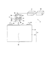
- FIG. 1 is a diagram illustrating a configuration of a battery temperature measuring apparatus 1 according to a first embodiment and a battery 10 to be measured.
- the battery temperature measuring device 1 according to the first embodiment roughly includes a sensor unit 12 and a temperature measuring unit 14.
- the sensor unit 12 includes a thermistor 16, a conductive member 18, and a sensor holder 20.
- the thermistor 16 includes a first electrode 24 and a second electrode 26 at both ends of a main body 22 made of ceramic.
- a main body 22 made of ceramic.
- the conductive member 18 is a wire having conductivity, and includes a first end portion 28 and a second end portion 30.
- a wire made of a material such as copper alloy, silver, gold, or aluminum.
- the sensor holder 20 is formed of a heat insulating material with low thermal conductivity, and the first conductive wire 32 and the second conductive wire 34 having conductivity are embedded therein.
- a foamed resin such as polypropylene or polyethylene as the heat insulating material.
- a copper wire as the 1st conducting wire 32 and the 2nd conducting wire 34.
- FIG. The second electrode 26 of the thermistor 16 is connected to the first conductive wire 32, and the second end 30 of the conductive member 18 is connected to the second conductive wire 34.
- the second electrode 26 of the thermistor 16 is connected to the temperature measuring unit 14 via the first conductive wire 32 of the sensor holder 20, and the second end 30 of the conductive member 18 is connected to the second conductive wire 34 of the sensor holder 20. It is connected to the temperature measurement unit 14 via.
- the operability in measuring the temperature of the battery 10 is improved.
- the sensor holder 20 is made of a heat insulating material, heat dissipation from the sensor holder 20 can be prevented.
- the temperature measurement unit 14 includes a measurement circuit shown in FIG. 2 and a calculation unit (not shown) that calculates the temperature of the battery 10 based on the voltage Vout (see FIG. 2) detected from the measurement circuit.
- the temperature of the battery 10 is measured from the change in the resistance value of the thermistor 16.
- the end portion 28 is simultaneously brought into contact with the case 36 of the battery 10.
- the case 36 of the battery 10 is made of metal and has conductivity. Therefore, the temperature of the battery 10 can be measured while using the case 36 of the battery 10 as a part of the measurement circuit.
- a positive electrode terminal 38 or a negative electrode terminal 40 is provided as a position where the first electrode 24 of the thermistor 16 and the first end portion 28 of the conductive member 18 in the sensor unit 12 are in contact with each other.
- An upper surface 42 of the case 36 and a front surface 44 of the case 36 facing a portion between a pair of electrodes (not shown) provided inside the battery 10 are conceivable.
- the temperature of the battery 10 can be measured more accurately.
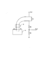
- FIG. 2 is a diagram illustrating an example of a circuit diagram of a measurement circuit provided in the temperature measurement unit 14.
- VCC is a power supply voltage
- R1, R2, and R3 are resistors
- Vout is a detected voltage.
- the case 36 of the battery 10 is used as a part of the measurement circuit.
- the resistance value R of the thermistor 16 at the temperature T can be expressed by the following formula, where Ro is the resistance value of the thermistor 16 at the temperature To.
- the thermistor constant is B.
- the battery temperature measuring apparatus 1 of the present embodiment can measure the temperature of the battery 10.
- the temperature of the battery 10 is measured by bringing the thermistor 16 into direct contact with the case 36 of the battery 10, so that the measurement error that occurs in the conventional radiation thermometer can be eliminated. it can.
- the heat capacity of the thermistor 16 and the conductive member 18 can be reduced. Therefore, the responsiveness of the thermistor 16 to the temperature change of the battery 10 can be improved, and the measurement error of the temperature of the battery 10 can be reduced.
- the thermal conductivity between the thermistor 16 or the conductive member 18 and the case 36 of the battery 10 can be improved.
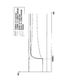
- FIG. 3 is a diagram illustrating the measurement accuracy and responsiveness in measuring the temperature of the battery 10.
- the surface temperature of the battery 10 greatly decreases with the start of measurement due to the large heat capacity of the sensor unit, and the measurement accuracy of the temperature of the battery 10 decreases. Also, the responsiveness is not good.
- the temperature measurement of the present embodiment since the heat capacity of the sensor unit 12 is small, the surface temperature of the battery 10 hardly changes, the measurement accuracy of the temperature of the battery 10 is improved, and the responsiveness is also improved. good.
- the temperature measurement accuracy of the battery 10 is improved and the responsiveness is improved, so that the temperature of the battery 10 can be measured accurately and at high speed. Then, by correcting the measurement result of the voltage between the terminals of the battery 10 based on the temperature of the battery 10 measured in this way, the voltage between the terminals of the battery 10 having temperature dependence is accurately determined. And the performance evaluation of the battery 10 can be accurately performed.
- FIG. 4 is a diagram illustrating the configuration of the battery temperature measuring device 2 according to the second embodiment and the battery 10 to be measured.
- the battery temperature measuring device 2 of the second embodiment has a conductive member 48 that is an elastic member as a configuration different from the battery temperature measuring device 1 of the first embodiment.
- Other configurations are common to the battery temperature measuring apparatus 1 of the first embodiment.
- a spring made of a material such as copper alloy, silver, gold, or aluminum can be used as the conductive member 48.
- a spring made of a copper alloy can be used.
- the conductive member 48 includes a first end 50 and a second end 52. The second end 52 is connected to the second conducting wire 34. Further, the conductive member 48 is formed longer than the thermistor 16.
- the first end 50 of the conductive member 48 having elasticity comes into contact with the first of the thermistor 16.
- One electrode 24 contacts. Therefore, when the thermistor 16 is brought into contact with the case 36 of the battery 10, the impact from the case 36 on the thermistor 16 is buffered. Therefore, the performance of the thermistor 16 can be maintained, and the temperature measurement accuracy of the battery 10 is reliably improved.
- FIG. 5 is a diagram illustrating the configuration of the battery temperature measuring device 3 according to the third embodiment and the battery 10 to be measured.
- the battery temperature measuring device 3 of the third embodiment has a windproof cover 54 as a difference from the battery temperature measuring device 2 of the second embodiment.
- the windproof cover 54 is formed over the circumference so as to surround the periphery of the thermistor 16 and the conductive member 48, and is a means for blocking the thermistor 16 and the conductive member 48 from the outside air.
- a heat insulating material such as a foamed resin such as polypropylene or polyethylene similar to the sensor holder 20 is used.
- Other configurations are common to the battery temperature measuring apparatus 2 of the second embodiment.
- the windproof cover 54 blocks the thermistor 16 and the conductive member 48 from the outside air, the characteristics of the thermistor 16 are not affected by fluctuations in the outside air. Therefore, the measurement accuracy of the temperature of the battery 10 is more reliably improved.
- variation of external air for example, the influence by the air conditioning of the room in which the battery temperature measuring device 3 and the battery 10 are placed, the influence of the wind generated by the elevation of the sensor unit 12 of the battery temperature measuring device 3, etc. Conceivable.
- FIG. 6 is a diagram illustrating the configuration of the battery temperature measuring device 4 according to the fourth embodiment and the battery 10 to be measured.
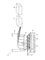
- FIG. 7 is an external view showing the battery temperature measuring device 4 of Example 4 and the battery to be measured.
- the battery temperature measuring device 4 of the fourth embodiment includes the same configuration as the battery temperature measuring device 3 of the third embodiment, and measures the temperatures of a plurality of batteries 10 at the same time.
- a sensor module 56 As a difference from the battery temperature measuring device 3 of the third embodiment, a sensor module 56, a lift drive unit 58, and a temperature correction calculation device 60 are provided.
- the sensor module 56 includes a plurality of sensor units 12.
- the elevating drive unit 58 is a means for elevating the sensor module 56.
- the temperature correction calculation unit 60 is a unit that estimates the true temperature of the battery 10 by correction calculation based on the voltage Vout detected by the calculation unit of the temperature measurement unit 14.
- the sensor module 56 is lowered with respect to the battery group in which the plurality of batteries 10 are arranged in the holder 62, and the temperatures of the plurality of batteries 10 are measured simultaneously.
- FIG. 8 is a flowchart when the temperature of the battery 10 is measured.
- the holder 62 is made to hold
- the temperature measurement position in the battery 10 that is, the position where the first electrode 24 of the thermistor 16 of each sensor unit 12 of the sensor module 56 and the first end 50 of the conductive member 48 are brought into contact with each other in the battery 10 is confirmed.
- the temperature measurement position in the battery 10 is the upper surface 42 of the case 36 of the battery 10.
- step S3 the sensor module 56 is lowered toward the battery 10 by the lift drive unit 58, and the sensor module 56 is brought into contact with the upper surface 42 of the case 36 of the battery 10 (step S4). Specifically, first, after the first end 50 of the conductive member 48 is brought into contact with the upper surface 42 of the case 36 of the battery 10, the first electrode 24 of the thermistor 16 is brought into contact. And it is confirmed that the sensor module 56 contacted the upper surface 42 of the case 36 of the battery 10 (step S5). And the measurement of the time when the sensor module 56 and the upper surface 42 of the case 36 of the battery 10 are in contact is started (step S6).
- the voltage V1 is detected as the voltage Vout of the measurement circuit when the time t has elapsed after the sensor module 56 and the upper surface 42 of the case 36 of the battery 10 are in contact (step S7).
- the sensor module 56 is raised to separate the first electrode 24 of the thermistor 16 and the first end 50 of the conductive member 48 from the upper surface 42 of the case 36 of the battery 10 (step S8). Thereby, the measurement of the temperature of the battery 10 is completed.
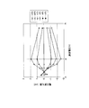
- the state of the passage of time and the change of the voltage detected by the temperature measuring unit 14 are shown in FIG.
- the voltage detected by the temperature measuring unit 14 gradually increases.
- the voltage corresponding to the true temperature is not reached.
- the true temperature of the battery 10 here is an actual temperature of the battery 10 to be measured.
- the temperature correction calculation unit 60 the voltage V0, V1 as the detected voltage Vout of the measurement circuit, the time t, and the change in the voltage Vout of the measurement circuit during the time t (for example, FIG.
- the voltage Vt corresponding to the true temperature of the battery 10 is estimated based on the slope of the curve shape as shown in FIG. Then, the true temperature of the battery 10 is obtained from the estimated voltage Vt. In this way, the temperature of the battery 10 can be measured in a short time.
- the temperature correction calculation unit 60 when estimating the voltage Vt corresponding to the true temperature of the battery 10, it is desirable to consider the ambient temperature around the battery 10 and the like.
- the voltage between the terminals of the battery 10 is measured while measuring the temperature of the battery 10 as in this embodiment. Then, by correcting the voltage between the terminals of the battery 10 based on the measured temperature of the battery 10, the voltage between the terminals of the battery 10 when the temperature of the battery 10 is the reference temperature is estimated and the performance of the battery Evaluate. For example, a case is considered where the measured temperature of the battery 10 is ⁇ 15 [° C.] with respect to the reference temperature, and the voltage between the terminals of the battery 10 at this time is measured as ⁇ [V]. At this time, as shown in FIG.
- the amount of change in the voltage with respect to the voltage between the terminals of the battery 10 is expected to be ⁇ 2.5 [mV]. Therefore, the voltage between the terminals of the battery 10 when the temperature of the battery 10 is the reference temperature is estimated to be ⁇ [V] +2.5 [mV].
- FIG. 10 shows an example of the relationship between the measured voltage between the terminals of the battery 10 and the amount of voltage change with respect to the voltage between the terminals of the battery 10 when the temperature of the battery 10 is the reference temperature. .
- the reference temperature is shown as 0 ° C.
- the voltage between the terminals of the battery 10 when the temperature of the battery 10 is the reference temperature is estimated by correcting the measured voltage between the terminals of the battery 10 using a correction table as shown in FIG. Then, based on the voltage between the terminals when the estimated temperature of the battery 10 is the reference temperature, the battery performance of the battery 10 for checking the internal resistance of the battery 10 is evaluated.
- measurement accuracy and responsiveness are improved in measuring the temperature of the plurality of batteries 10, and the temperature of the plurality of batteries 10 can be measured accurately and at high speed. And in the performance evaluation of a battery, the voltage between the terminals of the battery 10 which has temperature dependence can be grasped
- the performance of the battery 10 can be evaluated in a short time.
- FIGS. 6 and 7 an example in which the conductive member 48 having elasticity and the windproof cover 54 are used has been described.
- the present invention is not limited to this, and the conductive member having no elasticity as in the first embodiment.
- the present invention can be applied to an example in which the windproof cover 54 is not used and the example in which the windproof cover 54 is used without using the conductive member 48 having elasticity as in the second embodiment.
Landscapes
- Engineering & Computer Science (AREA)
- Manufacturing & Machinery (AREA)
- Chemical & Material Sciences (AREA)
- Chemical Kinetics & Catalysis (AREA)
- Electrochemistry (AREA)
- General Chemical & Material Sciences (AREA)
- Physics & Mathematics (AREA)
- General Physics & Mathematics (AREA)
- Nonlinear Science (AREA)
- Secondary Cells (AREA)
- Measuring Temperature Or Quantity Of Heat (AREA)
Abstract
Description
〔実施例1〕
図1は、実施例1の電池温度測定装置1の構成図および測定対象の電池10を示す図である。図1に示すように、実施例1の電池温度測定装置1は、大きく分けてセンサ部12と温度計測部14とを有する。センサ部12は、サーミスタ16と、導電性部材18と、センサホルダ20とを備える。

図4は、実施例2の電池温度測定装置2の構成図および測定対象の電池10を示す図である。図4に示すように、実施例2の電池温度測定装置2は、実施例1の電池温度測定装置1と異なる構成として、弾性部材の導電性部材48を有している。その他の構成は、実施例1の電池温度測定装置1と共通する。
図5は、実施例3の電池温度測定装置3の構成図および測定対象の電池10を示す図である。図5に示すように、実施例3の電池温度測定装置3は、実施例2の電池温度測定装置2と異なる点として、防風カバー54を有している。防風カバー54は、サーミスタ16およぶ導電性部材48の周囲を囲むように一周に亘って形成され、サーミスタ16と導電性部材48とを外気から遮断する手段である。本実施例では、防風カバー54の材質として、例えば、センサホルダ20と同様のポリプロピレンやポリエチレンなどの発泡樹脂のような断熱素材を使用する。その他の構成は、実施例2の電池温度測定装置2と共通する。
図6は、実施例4の電池温度測定装置4の構成図および測定対象の電池10を示す図である。図7は、実施例4の電池温度測定装置4および測定対象の電池を示す外観図である。図6と図7に示すように、実施例4の電池温度測定装置4は、前記の実施例3の電池温度測定装置3と同じ構成を含み、複数の電池10の温度を同時に測定する。
センサモジュール56は、複数のセンサ部12を備える。昇降駆動部58は、センサモジュール56を昇降させる手段である。温度補正演算部60は、温度計測部14の演算部にて検出した電圧Voutをもとに、補正演算により電池10の真の温度を推定する手段である。
2 電池温度測定装置
3 電池温度測定装置
4 電池温度測定装置
10 電池
12 センサ部
14 温度計測部
16 サーミスタ
18 導電性部材
20 センサホルダ
22 本体部
24 第1電極
26 第2電極
28 第1端部
30 第2端部
32 第1導線
34 第2導線
36 ケース
38 正極端子
40 負極端子
48 導電性部材
50 第1端部
52 第2端部
54 防風カバー
56 センサモジュール
60 温度補正演算装置
Claims (7)
- 電池の温度を測定する電池温度測定装置において、
第1電極と第2電極とを備えるサーミスタと、
第1端部と第2端部とを備える導電性部材と、
前記サーミスタの特性変化をもとに前記電池の温度を測定する温度計測部と、を有し、
前記サーミスタの前記第1電極を前記電池に備わる導電性を有するケースに接触させ、前記サーミスタの前記第2電極を前記温度計測部に接続させ、
前記導電性部材の前記第1端部を前記ケースに接触させ、前記導電性部材の前記第2端部を前記温度計測部に接続させること、
を特徴とする電池温度測定装置。 - 請求項1に記載する電池温度測定装置において、
第1導線と第2導線とが埋め込まれた断熱素材のセンサホルダを有し、
前記サーミスタの前記第2電極を前記ホルダの前記第1導線を経由して前記温度計測部に接続させ、前記導電性部材の前記第2端部を前記ホルダの前記第2導線を経由して前記温度計測部に接続すること、
を特徴とする電池温度測定装置。 - 請求項1または2に記載する電池温度測定装置において、
前記導電性部材は、前記サーミスタよりも長い弾性部材であること、
を特徴とする電池温度測定装置。 - 請求項1乃至3のいずれか一項に記載する電池温度測定装置において、
前記サーミスタおよび前記導電性部材の周囲を囲むカバーを有すること、
を特徴とする電池温度測定装置。 - 請求項1乃至4のいずれか一項に記載する電池温度測定装置において、
前記サーミスタと前記導電性部材とを備えるセンサ部が複数設けられたセンサモジュールを有すること、
を特徴とする電池温度測定装置。 - 電池の温度を測定する電池温度測定方法において、
第1電極と第2電極とを備えるサーミスタの前記第1電極を前記電池に備わる導電性を有するケースに接触させ、第1端部と第2端部とを備える導電性部材の前記第1端部を前記ケースに接触させ、前記サーミスタの前記第2電極と前記導電性部材の前記第2端部とが接続する温度計測部にて前記サーミスタの特性変化をもとに前記電池の温度を測定すること、
を特徴とする電池温度測定方法。 - 電池の製造方法において、
第1電極と第2電極とを備えるサーミスタの前記第1電極を前記電池に備わる導電性を有するケースに接触させ、第1端部と第2端部とを備える導電性部材の前記第1端部を前記ケースに接触させ、前記サーミスタの前記第2電極と前記導電性部材の前記第2端部とが接続する温度計測部にて前記サーミスタの特性変化をもとに前記電池の温度を測定しながら、前記電池の正極端子と負極端子との間の電圧である端子間電圧を測定し、
測定した前記電池の温度と測定した前記端子間電圧に対する補正量との関係を規定した補正テーブルを用いて、測定した前記端子間電圧を前記補正量に基づき補正することにより前記電池の温度が基準温度であるときの前記端子間電圧を推定して前記電池の性能評価を行うこと、
を特徴とする電池の製造方法。
Priority Applications (4)
| Application Number | Priority Date | Filing Date | Title |
|---|---|---|---|
| KR1020117003258A KR101265933B1 (ko) | 2010-04-28 | 2010-04-28 | 전지 온도 측정 장치 및 전지 온도 측정 방법, 전지의 제조 방법 |
| JP2010542866A JP5035428B2 (ja) | 2010-04-28 | 2010-04-28 | 電池温度測定装置および電池温度測定方法、電池の製造方法 |
| CN2010800025719A CN102308432B (zh) | 2010-04-28 | 2010-04-28 | 电池温度测定装置和电池温度测定方法、电池的制造方法 |
| PCT/JP2010/057603 WO2011135702A1 (ja) | 2010-04-28 | 2010-04-28 | 電池温度測定装置および電池温度測定方法、電池の製造方法 |
Applications Claiming Priority (1)
| Application Number | Priority Date | Filing Date | Title |
|---|---|---|---|
| PCT/JP2010/057603 WO2011135702A1 (ja) | 2010-04-28 | 2010-04-28 | 電池温度測定装置および電池温度測定方法、電池の製造方法 |
Publications (1)
| Publication Number | Publication Date |
|---|---|
| WO2011135702A1 true WO2011135702A1 (ja) | 2011-11-03 |
Family
ID=44861044
Family Applications (1)
| Application Number | Title | Priority Date | Filing Date |
|---|---|---|---|
| PCT/JP2010/057603 Ceased WO2011135702A1 (ja) | 2010-04-28 | 2010-04-28 | 電池温度測定装置および電池温度測定方法、電池の製造方法 |
Country Status (4)
| Country | Link |
|---|---|
| JP (1) | JP5035428B2 (ja) |
| KR (1) | KR101265933B1 (ja) |
| CN (1) | CN102308432B (ja) |
| WO (1) | WO2011135702A1 (ja) |
Cited By (2)
| Publication number | Priority date | Publication date | Assignee | Title |
|---|---|---|---|---|
| CN103542955A (zh) * | 2012-07-17 | 2014-01-29 | 昆山雅森电子材料科技有限公司 | 锂离子电池温度感应器 |
| JP2016090330A (ja) * | 2014-10-31 | 2016-05-23 | カルソニックカンセイ株式会社 | バッテリのパラメータ推定装置 |
Families Citing this family (10)
| Publication number | Priority date | Publication date | Assignee | Title |
|---|---|---|---|---|
| JP5900160B2 (ja) * | 2012-05-28 | 2016-04-06 | ソニー株式会社 | 二次電池の相対残容量推定方法、相対残容量推定装置、電池パック、電子機器及び電動車両 |
| US9488535B2 (en) | 2013-06-18 | 2016-11-08 | Ford Global Technologies, Llc | Battery pack thermistor test method |
| CH711926A1 (de) * | 2015-12-17 | 2017-06-30 | Greenteg Ag | Messaufbau zur Funktionskontrolle von wiederaufladbaren Batterien. |
| DE102016206666A1 (de) * | 2016-04-20 | 2017-10-26 | Robert Bosch Gmbh | Temperatursensor, Batteriesystem und Verfahren zum Montieren eines Batteriesystems |
| KR102105172B1 (ko) | 2017-01-03 | 2020-04-27 | 주식회사 엘지화학 | 내부의 온도를 측정할 수 있는 전지셀 |
| KR102256481B1 (ko) * | 2017-03-30 | 2021-05-27 | 주식회사 엘지에너지솔루션 | 전지셀용 충방전장치 및 그를 포함하는 전지셀용 검사시스템 |
| KR102503796B1 (ko) * | 2017-09-20 | 2023-02-23 | 삼성에스디아이 주식회사 | 배터리 보호 회로 |
| KR102327049B1 (ko) | 2017-11-06 | 2021-11-15 | 주식회사 엘지에너지솔루션 | 전지 모듈 |
| JP7243298B2 (ja) * | 2019-03-04 | 2023-03-22 | トヨタ自動車株式会社 | 電池評価方法 |
| CN111398827B (zh) * | 2020-03-18 | 2021-03-19 | 珠海迈巨微电子有限责任公司 | 环境温度预测方法、电池温度预测方法及电量计算方法 |
Citations (11)
| Publication number | Priority date | Publication date | Assignee | Title |
|---|---|---|---|---|
| JPS6133373U (ja) * | 1984-07-31 | 1986-02-28 | 新神戸電機株式会社 | ニツケル・カドミウム蓄電池 |
| JPS6332874A (ja) * | 1986-07-24 | 1988-02-12 | Matsushita Electric Works Ltd | 蓄電池の温度センサ取付構造 |
| JPH01177869U (ja) * | 1988-06-03 | 1989-12-19 | ||
| JPH0352958U (ja) * | 1989-09-30 | 1991-05-22 | ||
| JPH0461762A (ja) * | 1990-06-27 | 1992-02-27 | Matsushita Electric Works Ltd | 蓄電池装置 |
| JPH0785896A (ja) * | 1993-09-13 | 1995-03-31 | Sony Corp | 2次電池パック及びその充電装置 |
| JP2000277175A (ja) * | 1999-03-23 | 2000-10-06 | Sanyo Electric Co Ltd | 電池の温度上昇監視方法及び装置 |
| US6152597A (en) * | 1997-06-27 | 2000-11-28 | Potega; Patrick H. | Apparatus for monitoring temperature of a power source |
| WO2006115342A1 (en) * | 2005-04-08 | 2006-11-02 | U-Nisum Technology Co., Ltd | Circuit and chip for protecting battery, method of manufacturing the same and battery pack having the same |
| JP2008021569A (ja) * | 2006-07-14 | 2008-01-31 | Toyota Motor Corp | 二次電池システム |
| JP2008519253A (ja) * | 2004-11-03 | 2008-06-05 | リエゾン、エレクトロニク−メカニク、エルウエム、ソシエテ、アノニム | 温度センサーを備えたケルビンコネクタ |
Family Cites Families (5)
| Publication number | Priority date | Publication date | Assignee | Title |
|---|---|---|---|---|
| JP3190854B2 (ja) * | 1997-05-23 | 2001-07-23 | 静岡日本電気株式会社 | 充電器 |
| JP2002124305A (ja) * | 2000-10-13 | 2002-04-26 | Matsushita Electric Ind Co Ltd | 電池パック |
| KR100801635B1 (ko) * | 2004-11-02 | 2008-02-05 | 주식회사 엘지화학 | 전지 팩의 전지 전압 및 온도 측정용 부재 |
| JP2009158143A (ja) * | 2007-12-25 | 2009-07-16 | Sony Corp | 燃料電池および温度測定方法 |
| CN101609978A (zh) * | 2008-06-20 | 2009-12-23 | 鸿富锦精密工业(深圳)有限公司 | 电池过热保护装置和方法 |
-
2010
- 2010-04-28 WO PCT/JP2010/057603 patent/WO2011135702A1/ja not_active Ceased
- 2010-04-28 CN CN2010800025719A patent/CN102308432B/zh not_active Expired - Fee Related
- 2010-04-28 KR KR1020117003258A patent/KR101265933B1/ko not_active Expired - Fee Related
- 2010-04-28 JP JP2010542866A patent/JP5035428B2/ja not_active Expired - Fee Related
Patent Citations (11)
| Publication number | Priority date | Publication date | Assignee | Title |
|---|---|---|---|---|
| JPS6133373U (ja) * | 1984-07-31 | 1986-02-28 | 新神戸電機株式会社 | ニツケル・カドミウム蓄電池 |
| JPS6332874A (ja) * | 1986-07-24 | 1988-02-12 | Matsushita Electric Works Ltd | 蓄電池の温度センサ取付構造 |
| JPH01177869U (ja) * | 1988-06-03 | 1989-12-19 | ||
| JPH0352958U (ja) * | 1989-09-30 | 1991-05-22 | ||
| JPH0461762A (ja) * | 1990-06-27 | 1992-02-27 | Matsushita Electric Works Ltd | 蓄電池装置 |
| JPH0785896A (ja) * | 1993-09-13 | 1995-03-31 | Sony Corp | 2次電池パック及びその充電装置 |
| US6152597A (en) * | 1997-06-27 | 2000-11-28 | Potega; Patrick H. | Apparatus for monitoring temperature of a power source |
| JP2000277175A (ja) * | 1999-03-23 | 2000-10-06 | Sanyo Electric Co Ltd | 電池の温度上昇監視方法及び装置 |
| JP2008519253A (ja) * | 2004-11-03 | 2008-06-05 | リエゾン、エレクトロニク−メカニク、エルウエム、ソシエテ、アノニム | 温度センサーを備えたケルビンコネクタ |
| WO2006115342A1 (en) * | 2005-04-08 | 2006-11-02 | U-Nisum Technology Co., Ltd | Circuit and chip for protecting battery, method of manufacturing the same and battery pack having the same |
| JP2008021569A (ja) * | 2006-07-14 | 2008-01-31 | Toyota Motor Corp | 二次電池システム |
Cited By (3)
| Publication number | Priority date | Publication date | Assignee | Title |
|---|---|---|---|---|
| CN103542955A (zh) * | 2012-07-17 | 2014-01-29 | 昆山雅森电子材料科技有限公司 | 锂离子电池温度感应器 |
| JP2016090330A (ja) * | 2014-10-31 | 2016-05-23 | カルソニックカンセイ株式会社 | バッテリのパラメータ推定装置 |
| CN107110914A (zh) * | 2014-10-31 | 2017-08-29 | 康奈可关精株式会社 | 电池的参数估计装置 |
Also Published As
| Publication number | Publication date |
|---|---|
| KR101265933B1 (ko) | 2013-05-20 |
| CN102308432B (zh) | 2013-12-18 |
| JPWO2011135702A1 (ja) | 2013-07-18 |
| KR20110136777A (ko) | 2011-12-21 |
| JP5035428B2 (ja) | 2012-09-26 |
| CN102308432A (zh) | 2012-01-04 |
Similar Documents
| Publication | Publication Date | Title |
|---|---|---|
| JP5035428B2 (ja) | 電池温度測定装置および電池温度測定方法、電池の製造方法 | |
| JP5679233B2 (ja) | 電池寿命予測装置及び電池寿命予測システム | |
| TWI879219B (zh) | 電池監測方法和設備 | |
| CN112858933B (zh) | 用于电池模块的传感器系统 | |
| CN102735888A (zh) | 探针结构与探针制造方法 | |
| WO2023179255A1 (zh) | 一种充电装置、方法及相关设备 | |
| CN212963756U (zh) | 一种温度传感器、温度传感器组及测温装置 | |
| JP6344101B2 (ja) | ガス検出装置 | |
| CN118057677A (zh) | 汇流条组件及电流测量装置 | |
| CN108120933B (zh) | 非对称式电池检测装置 | |
| JP5842759B2 (ja) | 温度推定方法及び温度推定装置 | |
| JPH0640712B2 (ja) | 充電完了検知器 | |
| US11946813B2 (en) | Battery module detecting high temperature of battery cell and method for detecting high temperature of battery cell | |
| KR20190026491A (ko) | 전지 성능 추정 장치 및 방법 | |
| CN216283995U (zh) | 测温结构、充电装置及机动车辆 | |
| JP3418407B2 (ja) | プリント配線板の測温型外部接続機構 | |
| WO2024140959A1 (zh) | 一种端子测温结构及一种连接器 | |
| TWI491857B (zh) | Temperature sensing means | |
| JP2012079483A (ja) | 電池昇温回路および電池昇温装置 | |
| CN214845452U (zh) | 一种电阻器件 | |
| TWI412750B (zh) | Probe circuit | |
| CN201801560U (zh) | 带有测温装置的压线辊 | |
| CN111103064A (zh) | 温度传感器 | |
| CN216670175U (zh) | 多晶硅电迁移测试结构 | |
| JP4894582B2 (ja) | ウェハテスト方法及びプローブカード |
Legal Events
| Date | Code | Title | Description |
|---|---|---|---|
| WWE | Wipo information: entry into national phase |
Ref document number: 201080002571.9 Country of ref document: CN |
|
| WWE | Wipo information: entry into national phase |
Ref document number: 2010542866 Country of ref document: JP |
|
| ENP | Entry into the national phase |
Ref document number: 20117003258 Country of ref document: KR Kind code of ref document: A |
|
| 121 | Ep: the epo has been informed by wipo that ep was designated in this application |
Ref document number: 10850719 Country of ref document: EP Kind code of ref document: A1 |
|
| NENP | Non-entry into the national phase |
Ref country code: DE |
|
| 122 | Ep: pct application non-entry in european phase |
Ref document number: 10850719 Country of ref document: EP Kind code of ref document: A1 |