WO2011132278A1 - ボタン取付用下方ダイ - Google Patents
ボタン取付用下方ダイ Download PDFInfo
- Publication number
- WO2011132278A1 WO2011132278A1 PCT/JP2010/057080 JP2010057080W WO2011132278A1 WO 2011132278 A1 WO2011132278 A1 WO 2011132278A1 JP 2010057080 W JP2010057080 W JP 2010057080W WO 2011132278 A1 WO2011132278 A1 WO 2011132278A1
- Authority
- WO
- WIPO (PCT)
- Prior art keywords
- button
- fabric
- lower die
- die body
- mounting member
- Prior art date
- Legal status (The legal status is an assumption and is not a legal conclusion. Google has not performed a legal analysis and makes no representation as to the accuracy of the status listed.)
- Ceased
Links
Images





Classifications
-
- A—HUMAN NECESSITIES
- A41—WEARING APPAREL
- A41H—APPLIANCES OR METHODS FOR MAKING CLOTHES, e.g. FOR DRESS-MAKING OR FOR TAILORING, NOT OTHERWISE PROVIDED FOR
- A41H37/00—Machines, appliances or methods for setting fastener-elements on garments
Definitions
- the present invention relates to a lower die for attaching a button, and more particularly to a lower die (lower die) on which a button attaching member is placed when a snap button or the like is attached to a cloth with the button attaching member.
- the upper die When attaching a button such as a female snap or a male snap to a fabric using a button mounting member having a disk-shaped base portion and a post portion protruding from the center of the base portion, the upper die is placed above the horizontally disposed fabric. After holding the button and placing the button mounting member on the lower die below the fabric, the upper die is lowered. As a result, the button pushes down the fabric, and the post portion of the button mounting member in a stationary state penetrates the fabric from below to above. The post portion that has penetrated the fabric is then crimped by the upper die after passing through the button mounting opening, whereby the button is attached to the fabric.
- a button such as a female snap or a male snap
- the post part of the button mounting member tries to penetrate the cloth only by the worker's holding.
- the post portion entrains the fabric, and the fabric is pulled into the attachment opening side of the upper button.
- the post portion may not be crimped as expected, and a bad attachment may occur, or the appearance may be impaired due to wrinkles on the fabric.
- Japanese Utility Model Publication No. 60-37019 caulking the fabric between the fabric pressing surface of the upper die and the fabric pressing surface of the lower die An apparatus is disclosed.
- this technique since it is necessary to incorporate a component that defines the fabric pressing surface in both the upper die and the lower die, there is a problem that the caulking device becomes large and costs increase.
- the present invention has been made paying attention to the problems as described above, and its purpose is to cost-effectively carry the cloth by the post portion of the button mounting member when the button is attached to the cloth using the button mounting member. It is to provide a button mounting lower die which can be advantageously prevented.
- a cloth (a cloth, a cloth, a post-shaped button attaching member having a plate-like base portion and a post portion protruding from the center of the base portion) Cloth, non-woven fabric, felt, leather, resin sheet, etc.
- buttons female snaps, male snaps, etc.
- Each of the split molds includes a fabric support surface that supports a lower surface of the fabric, and the split mold has a post portion of the button mounting member passing through the fabric, and at least a part of the fabric support surface is a fabric
- a button attach lower die is provided that is radially movable between disengaged non-overlapping positions.
- the post portion of the button mounting member is penetrating the fabric, i.e., the tip of the post portion is in contact with the lower surface of the fabric, the post portion starts to break through the fabric, and then the post portion substantially penetrates the fabric.
- the split die of the button attaching lower die is in an overlapping position where the cloth supporting surface partially overlaps the bottom surface of the button and the cloth in the vertical direction. With this overlap, the fabric is securely sandwiched between the button and the split mold, and the fabric is firmly stretched. This prevents the cloth from being taken upward by the post portion.
- the split mold of the button mounting lower die moves to the non-overlap position radially outside the overlap position, and the fabric support surface of each split mold It deviates radially outward from a range facing the bottom surface in the vertical direction.
- the number of split molds arranged around the lower die body is at least two, preferably about three to six, but is not limited thereto.
- each of the split dies includes an inclined surface that is inclined radially inward upward, and the inclined surface of the lower die body when the split mold is pushed down with respect to the lower die body.
- the split mold is displaced from the overlap position to the non-overlap position by engaging with the peripheral edge or the peripheral edge of the base portion of the button mounting member placed on the lower die body.
- the inclined surface of the split mold comes into contact with the peripheral part of the lower die body in a stationary state or the peripheral part of the base part of the button mounting member placed on the lower die body.
- the split mold is continuously displaced outward in the radial direction by slipping outward in the radial direction with respect to the peripheral portion in response to the pushed-down force.
- Each split mold is urged radially inward using elastic means such as a spring, and when the split mold is pushed down, the engagement between the inclined surface and the peripheral portion resists the bias of the elastic means.
- the split mold can be configured to move radially outward.
- the split mold has a radially inner end of the dough support surface in a radial position of a peripheral portion of the lower die body or a base portion of a button mounting member placed on the lower die body. It is possible to move outward in the radial direction to the enlarged diameter position that comes to the radial position of the periphery. As the split mold is displaced radially outward from the overlap position to the enlarged diameter position, the base part of the button mounting member approaches the fabric, and the base part supports the lower surface of the fabric at the enlarged diameter position of the split mold. The post part is crimped by the upper die.
- the button mounting lower die when the post portion of the button mounting member placed on the lower die body penetrates the fabric, the bottom surface of the button and the split fabric supporting surface are partially in the vertical direction. Therefore, when the post portion penetrates the fabric, the fabric is not entrained upward. Further, since the fabric is sandwiched between the button itself and the lower die, it is advantageous in terms of cost as compared with the conventional technique in which the fabric is sandwiched between both the upper die and the lower die.
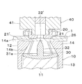
- FIG. 1 shows an upper die, a female snap, a cloth, a button attaching member, and a lower die when a female snap is attached to a cloth using a button attaching lower die (lower die) according to an embodiment of the present invention.
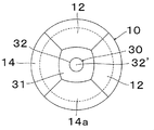
- FIG. 2 is a plan view of the split mold at the reduced diameter position as viewed from above.
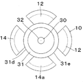
- FIG. 3 is a plan view of the split mold in the enlarged diameter position as viewed from above.
- FIG. 4 is a longitudinal cross-sectional explanatory view showing a process of attaching the female snap to the cloth, and shows a state before the post portion of the button attaching member contacts the cloth.
- FIG. 1 shows an upper die, a female snap, a cloth, a button attaching member, and a lower die when a female snap is attached to a cloth using a button attaching lower die (lower die) according to an embodiment of the present invention.
- FIG. 2 is a plan view of the split mold at the reduced diameter position as viewed from above.
- FIG. 5 is a longitudinal cross-sectional explanatory view showing a process of attaching the female snap to the cloth, and shows a state where the tip of the post portion of the button attachment member is in contact with the cloth.
- FIG. 6 is a longitudinal cross-sectional explanatory view showing a process of attaching the female snap to the cloth, and shows a state immediately before the post portion of the button attaching member penetrates the cloth.
- FIG. 7 is a longitudinal cross-sectional explanatory view showing a process of attaching the female snap to the cloth, and shows a state where the post portion of the button attaching member penetrates the cloth.
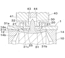
- FIG. 8 is a longitudinal cross-sectional explanatory view showing a process of attaching the female snap to the cloth, and shows a state where the lowering of the upper die body is completed.
- FIG. 9 is an explanatory longitudinal cross-sectional view illustrating a state where the post portion of the button mounting member is crimped.
- FIG. 10 is a partial explanatory view of a longitudinal section showing a modification of the lower die body.
- FIG. 11 is a partial cross-sectional explanatory view showing a state where the split mold is pushed down with respect to the lower die body of FIG.
- FIG. 12 is a partial cross-sectional explanatory view showing a modification of the upper surface (fabric support surface) of the split mold.
- FIG. 1 shows an upper die when a female snap 20 as an example of a button is attached to a fabric 1 using a button attaching lower die (hereinafter also simply referred to as “lower die”) 10 according to an embodiment of the present invention.
- lower die a button attaching lower die
- FIG. 1 shows the arrangement structure in the up-down direction (axial direction) of the (upper metal mold
- the female snap 20 is a resin molded product, and includes a disk-shaped bottom portion 21, a cylindrical circumferential side portion 22 that extends upward from a radially outer end portion of the bottom portion 21, and a radial direction from the upper end portion of the circumferential side portion 22.
- a space on the bottom 21 and radially inward of the peripheral side 22 serves as a projection receiving portion 24 that detachably receives a male snap projection (not shown).
- a bulging portion 22 ′ bulging inward in the radial direction is formed at the upper end portion of the circumferential side portion 22.
- the protruding portion 22 When the protruding portion of the male snap is attached to and detached from the protrusion receiving portion 24, the protruding portion 22 'engages with a protruding portion (not shown) that expands radially outward provided at the protruding end side end of the protruding portion. Then, the circumferential side portion 22 is elastically deformed radially outward.
- an attachment opening 25 is provided at the center of the bottom portion 21 of the female snap 20, an attachment opening 25 is provided for allowing the post portion 32 of the button attachment member 30 to pass when the female snap 20 is attached to the fabric 1.
- a protruding portion 26 that protrudes slightly in an obtuse triangular shape in cross section is provided at the radially outer end of the lower surface 21 ′ of the bottom 21.
- the button mounting member 30 is a member made of resin or metal, and includes a substantially disc-shaped base portion 31 and a post portion 32 extending concentrically with the base portion 31 upward from the center of the base portion 31.
- the portion 32 is tapered and the tip 32 'is sharp.
- the lower surface 31a of the base portion 31 is a curved surface that slightly protrudes downward.
- an outer horizontal plane 31c is formed that extends to the radially outer end of the base portion 31 along the horizontal (a plane orthogonal to the axis of the button mounting member 30).
- the base 31 further includes a peripheral side surface 31d parallel to the axis between the radially outer end of the lower surface 31a and the radially outer end of the outer horizontal surface 31c. Accordingly, the base portion 31 has, at its radially outer end, a lower peripheral portion where the peripheral side surface 31d and the lower surface 31a intersect, and an upper peripheral portion (approximately 90 degrees in vertical section where the peripheral side surface 31d and the outer horizontal surface 31c intersect). (Hereinafter referred to as “upper edge”) 31e.
- the upper die 40 is housed in a substantially cylindrical upper die body 41 whose upper end is connected to a lifting unit (not shown) of the press device and a cavity 43 along the axis of the upper die body 41, and moves up and down with respect to the upper die body 41.
- the upper die body 41 has a cylindrical button holding portion 42 that protrudes downward from the lower surface thereof.
- the button holding portion 42 has an inner diameter equal to the diameter of the cavity 43 and extends the cavity 43 downward.
- the button holding portion 42 has a size that substantially matches the protrusion receiving portion 24 of the female snap 20, and the female snap 20 is attached to the button holding portion 42 from the protrusion receiving portion 24 when attached to the fabric 1.
- the bulging portion 22 ′ of the peripheral side portion 22 of the female snap 20 is slightly elastically displaced radially outward, so that the bulging portion 22 ′ attempts to restore the radial inner side to the button holding portion 42.
- the female snap 20 is held by the button holding portion 42 by pressing the outer peripheral surface.
- the lower die 10 is disposed around a cylindrical lower die body 11 on which the button attachment member 30 is placed on the upper surface 11 ′, and the lower die body 11 and the button attachment member 30 placed on the lower die body 11.
- four split molds 12 and elastic means such as a spring for biasing each split mold 12 radially inward are provided.
- the upper surface 11 ′ of the lower die body 11 is a concave curved surface that matches the lower surface 31 a of the base portion 31 of the button mounting member 30.
- the state in which the button mounting member 30 is placed on the upper surface 11 ′ of the lower die body 11 is also referred to as a “placed state”.
- Each split mold 12 has a shape obtained by dividing a cylinder into four parts at intervals of 90 degrees in the circumferential direction, and has a split mold base end portion 13 having a constant radial thickness, and extends upward from the upper end of the split mold base end portion 13. And a fabric support portion 14 whose thickness gradually increases inward in the radial direction.
- the outer surface in the radial direction of the split mold base end portion 13 and the outer surface in the radial direction of the dough support portion 14 are flush, and the split mold base end portion 13 is the outer surface of the lower die body 11 and the button in the mounted state.
- the mounting member 30 has an inner side surface 13 ′ that matches the peripheral side surface 31 d of the base portion 31.
- the dough support 14 includes a dough support surface 14 a that is a fan-shaped upper surface extending inward in the radial direction from the split base end 13 and horizontally extending (see FIG. 2), and an inner surface 13 of the split base end 13. And an inclined surface 14b extending from the upper end of 'to the radially inner end of the fabric support surface 14a.
- FIG. 2 is a plan view of the lower die 10 and the button attachment member 30 in the placed state shown in FIG. 1 as viewed from above. In this state, each split mold 12 is located at the innermost radial position where the inner side surface 13 ′ of the split mold base end portion 13 is in contact with the outer peripheral surface of the lower die body 11 and the peripheral side surface 31 d of the button attachment member 30 in the mounted state.
- reduced diameter position (Hereinafter referred to as “reduced diameter position”).
- the lower end of the inclined surface 14 b of the dough support portion 14 (the upper end of the inner side surface 13 ′ of the split base end portion 13) is the upper edge of the base portion 31 of the button mounting member 30. 31e is touched.
- the split mold 12 moves outward in the radial direction against the urging force of the elastic means while moving downward with respect to the lower die body 11 from the reduced diameter position.
- the fabric support surface 14a of the split mold 12 in the reduced diameter position, is slightly above the tip 32 'of the post portion 32 of the button mounting member 30, and the fabric support surface 14a is The degree of expansion inward in the radial direction is slightly inward in the radial direction from the protrusion 26 on the lower surface 21 ′ of the bottom portion 21 of the concentric female snap 20.
- the radially inner end side of the fabric support surface 14 a of the split mold 12 is substantially parallel to the radially outer surface of the fabric support portion 14, and is adjacent in the circumferential direction at the reduced diameter position. The side surfaces of the split molds 12 are in contact with each other.
- FIG. 3 is a plan view of a state in which each split mold 12 has moved from the reduced diameter position to the most radially outer position (hereinafter referred to as “expanded position”) from above.
- the radially inner end side of the fabric support surface 14a is in contact with the peripheral side surface 31d of the base portion 31 of the button mounting member 30 and is at the radial position of the upper edge 31e (see FIG. 8).
- the female snap 20 is held by the button holding portion 42 of the upper die 40, and the button attachment member 30 is placed on the upper surface 11 ′ of the lower die body 11 of the lower die 10, and the split die 12 is brought into the reduced diameter position. set.
- the upper die 40 is lowered from this state (the vertical die main body 11 and the button mounting member 30 are stationary in the vertical direction), as shown in FIG. 4, the fabric 1 has a lower surface 21 ′ of the bottom 21 of the female snap 20, The lower die 10 is sandwiched between the cloth support surface 14a of the cloth support portion 14 of the split mold 12.
- the radially inner end of the fabric support surface 14a is slightly radially inward of the protrusion 26 of the female snap 20 as described above, a part of the fabric support surface 14a on the radially inner side is the fabric 1
- the support surface 14a partially overlaps in the vertical direction (the split mold 12 is at the overlap position).
- the fabric 1 is firmly stretched radially inward of the fabric support surface 14a.
- the female snap 20 pushes down the split mold 12 at the reduced diameter position via the fabric 1 as shown in FIG. 5, and the post portion 32 of the button mounting member 30.
- the front end 32 ′ of the contact with the lower surface of the fabric 1 starts to penetrate the fabric 1.
- the inclined surface 14b of the fabric support portion 14 is engaged with the upper edge 31e of the base portion 31 of the button mounting member 30 and slips, and is displaced radially outward.
- the inclined surface 14b of the split mold 12 slides with respect to the upper edge 31e of the button mounting member 30 and is further displaced radially outward, and the radially inner end of the fabric support surface 14a enters or falls into the button bottom surface corresponding range.
- the overlap portion between the female snap 20 and the split mold 12 sandwiches and tensions the fabric 1 until just before the post portion 32 penetrates the fabric 1.
- the dough 1 is not taken upwards.
- the protrusion 26 on the lower surface 21 ′ of the female snap 20 serves as a slip stopper that prevents the fabric 1 from slipping between the female snap 20 and the split mold 12 when the fabric 1 is penetrated by the post portion 32. As a result, the tension of the fabric 1 is strengthened.
- the split mold 12 When the upper die 40 is further lowered from the state of FIG. 6, as shown in FIG. 7, the split mold 12 is further displaced downward and radially outward, and the tip 32 of the post portion 32 of the button mounting member 30 penetrating the cloth 1. 'Enters the mounting opening 25 of the female snap 20. At this time, the cloth support surface 14a is outside the range corresponding to the bottom surface of the button, and there is no overlap between the female snap 20 and the split mold 12 (the split mold 12 is in the non-overlap position). When the upper die 40 continues to lower to the lower limit, the split mold 12 is in the diameter-expanded position as shown in FIG. 8, and the fabric 1 is between the bottom portion 21 of the female snap 20 and the base portion 31 of the button mounting member 30.
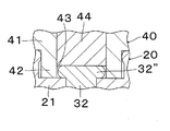
- the post portion 32 of the button attachment member 30 After being compressed, the post portion 32 of the button attachment member 30 enters the cavity 43 of the upper die body 41 through the attachment opening 25 of the female snap 20. By moving the punch 44 of the upper die 40 downward relative to the upper die body 41 from this state, the post portion 32 of the button mounting member 30 is crimped as shown in FIG. 9 (see the crimped post portion). Female snap 20 is fixed to the fabric 1.
- FIG. 10 shows a modification in which only the lower die body 11 in the lower die 10 described above is replaced with another lower die body 51, and the same reference numerals as those in FIG.
- the lower die body 51 has an upper surface 52 that is recessed downward from the upper end surface so as to match the shape of the base portion 31 in order to place the base portion 31 of the button mounting member 30, and the upper end portion of the peripheral side surface
- the peripheral part 53 which chamfered diagonally in parallel with the inclined surface 14b of the split mold 12 is included.
- the upper surface 52 has a circular shape.
- the present invention is not limited to this.
- the base portion has a polygonal shape
- the upper surface 52 also has a polygonal shape.
- FIG. 12 is an enlarged view showing a modification of the split mold, and the same reference numerals as those in FIG.
- Fine irregularities 64 are provided on the radially inner end of the cloth support surface 63 of the split mold 62.
- the projections and depressions 64 play a role of preventing the dough 1 from slipping between the female snap 20 and the split mold 62 when the dough 1 is penetrated by the post portion 32 together with the protrusion 26 on the lower surface 21 ′ of the female snap 20. Thereby, the tension of the fabric 1 is further strengthened.
Landscapes
- Engineering & Computer Science (AREA)
- Textile Engineering (AREA)
- Slide Fasteners, Snap Fasteners, And Hook Fasteners (AREA)
- Footwear And Its Accessory, Manufacturing Method And Apparatuses (AREA)
Abstract
ボタン取付部材を用いてボタンを生地に取り付ける際、ボタン取付部材のポスト部による生地の連行をコスト的に有利に防ぐことができる下方ダイを提供する。下方ダイ(10)を、ボタン取付部材(30)が上面(11')に載置される円柱状の下方ダイ本体(11)と、下方ダイ本体(11)の周囲に一例として四つ配置され、上方ダイ(40)の下方への移動によってボタン(20)及び生地(1)を介して下方ダイ本体(11)に対し下方に押し下げられる割型(12)とから構成する。割型(12)は、ボタン取付部材(30)のポスト部(32)が生地(1)を貫通する時、割型(12)の生地支持面(14a)の半径方向内側部分が、生地(1)の上面に接するボタン(20)の底面(21')に上下方向において対応する生地(1)の下面におけるボタン底面対応範囲内に存在し、ポスト部(32)が生地(1)を貫通した後、割型(12)の生地支持面(14a)はボタン底面対応範囲から外れる。
Description
本発明はボタン取付用下方ダイに関し、更に詳しくは、スナップボタン等をボタン取付部材で生地に取り付ける際にボタン取付部材を載置する下方ダイ(下金型)に関する。
円板状のベース部及びベース部の中央から突出するポスト部を有するボタン取付部材を用いて雌スナップ、雄スナップ等のボタンを生地に取り付ける場合、水平に配した生地の上方にて上方ダイにボタンを保持させ、生地の下方にて下方ダイ上にボタン取付部材を載置した後、上方ダイを降下させる。これにより、ボタンが生地を押し下げ、この生地を、静止状態のボタン取付部材のポスト部が下方から上方へと突き抜ける。生地を貫通したポスト部は、次いでボタンの取付用開口を通った後、上方ダイによって加締められ、これにより、ボタンが生地に取り付けられる。
上述したボタンの生地への取り付け時において、作業者が生地を張った状態で水平に保持しているが、作業者の保持のみでは、ボタン取付部材のポスト部が生地を突き抜けようとする際、ポスト部が生地を連行し、生地が上方のボタンの取付開口側に引き込まれる場合がある。このような場合、例えば、ポスト部が所期通り加締められず、ボタンの取り付け不良が生じたり、生地に皺が生じて美観が損なわれるといった弊害が生じ得る。機械的に生地を張ってポスト部による生地の引き込みを防ぐ技術として、実開昭60-37019号公報に、上方ダイの生地押さえ面と下方ダイの生地押さえ面との間で生地を挟み込む加締装置が開示されている。しかしながら、この技術では、上方ダイと下方ダイの両方に生地押さえ面を規定する構成要素を組み込む必要があるため、加締装置が大掛かりとなってコストが嵩むという問題がある。
本発明は、上記のような問題点に着目してなされたもので、その目的は、ボタン取付部材を用いてボタンを生地に取り付ける際、ボタン取付部材のポスト部による生地の連行をコスト的に有利に防ぐことができるボタン取付用下方ダイを提供することにある。
上記課題を解決するため、本発明によれば、板状のベース部及びベース部の中央から突出するポスト部を有するボタン取付部材の該ポスト部を水平に配した生地(生地には、織物、布、不織布、フェルト、皮、樹脂シート等が含まれる。)の下方から上方に貫通させ、次いでボタン(雌スナップ、雄スナップ等)の取付用開口に通した後、該ポスト部を上方ダイで加締めることによってボタンを生地に取り付ける際に使用するボタン取付用下方ダイであって、ボタン取付部材が上面に載置される円柱状の下方ダイ本体と、下方ダイ本体の周囲に複数配置され、前記上方ダイの相対的な下方への移動(上方ダイが静止し、下方ダイが上方に移動する場合を含む)によってボタン及び生地を介して下方ダイ本体に対し下方に押し下げられる割型とを備え、前記各割型は、生地の下面を支持する生地支持面を含み、前記割型は、前記ボタン取付部材のポスト部が生地を貫通中、前記生地支持面の少なくとも一部が、生地の上面に接するボタンの底面に上下方向において対応する生地の下面におけるボタン底面対応範囲内に存在するオーバーラップ位置と、ポスト部が生地を貫通した後、前記生地支持面が前記ボタン底面対応範囲から外れる非オーバーラップ位置との間を半径方向に移動可能であるボタン取付用下方ダイが提供される。
本発明では、ボタン取付部材のポスト部が生地を貫通中、すなわち、ポスト部の先端が生地の下面に接してポスト部が生地を突き破り始め、その後、ポスト部が生地を実質的に突き抜けるまでの間、ボタン取付用下方ダイの割型は、その生地支持面がボタンの底面と生地を挟んで上下方向に部分的にオーバーラップするオーバーラップ位置にある。このオーバーラップ部分で生地がボタンと割型間に確実に挟み付けられて生地がしっかりと張られる。これにより、ポスト部による生地の上方への連行が防止される。ボタン取付部材のポスト部が生地を突き抜けた後は、ボタン取付用下方ダイの割型はオーバーラップ位置よりも半径方向外側の非オーバーラップ位置に移動し、各割型の生地支持面はボタンの底面に上下方向に対向する範囲から半径方向外側に外れる。
本発明において、下方ダイ本体の周囲に配置される割型の数としては、少なくとも二つ、好ましくは三つから六つ程度であるが、これらに限定されるものではない。
本発明の一実施形態において、前記各割型は、上方へと半径方向内側に傾斜する傾斜面を含み、前記傾斜面は、割型が下方ダイ本体に対し押し下げられる際、前記下方ダイ本体の周縁部又は下方ダイ本体に載置されたボタン取付部材のベース部の周縁部と係合して、割型を前記オーバラップ位置から非オーバーラップ位置へと変位させる。この場合、割型が下方に移動するに従って、割型の傾斜面が、静止状態にある下方ダイ本体の周縁部又は下方ダイ本体に載置されたボタン取付部材のベース部の周縁部に当接し、押し下げられる力を受けて周縁部に対し半径方向外側に滑ることにより、割型が半径方向外側へと連続的に変位する。なお、スプリング等の弾性手段を用いて各割型を半径方向内側に付勢しておき、割型が押し下げられる際、上記傾斜面と周縁部の係合によって弾性手段の付勢に抗して割型が半径方向外側に移動するように構成することができる。
本発明の一実施形態において、前記割型は、前記生地支持面の半径方向内側端が前記下方ダイ本体の周縁部の半径方向位置又は下方ダイ本体に載置されたボタン取付部材のベース部の周縁部の半径方向位置に来る拡径位置まで半径方向外側に移動可能である。割型がオーバラップ位置から拡径位置へと半径方向外側に変位するにつれ、ボタン取付部材のベース部が生地に近付き、割型の拡径位置においてベース部が生地の下面を支持し、この状態でポスト部が上方ダイによって加締められる。
本発明に係るボタン取付用下方ダイでは、下方ダイ本体上に載置されたボタン取付部材のポスト部が生地を貫通する時、ボタンの底面と割型の生地支持面とが上下方向に部分的にオーバーラップし、生地を確実に挟み付けてしっかりと生地を緊張させることができるため、ポスト部が生地を突き抜ける際、生地を上方に連行するようなことはない。また、ボタン自体と下方ダイとで生地を挟む構造であるため、上方ダイと下方ダイの両方で生地を挟む従来技術に比べコスト的にも有利である。
以下、本発明の好適な実施形態を図面を参照しつつ説明する。図1は、本発明の一実施形態に係るボタン取付用下方ダイ(以下単に「下方ダイ」ともいう)10を使用してボタンの一例としての雌スナップ20を生地1に取り付ける際の、上方ダイ(上金型)40、雌スナップ20、生地1、ボタン取付部材30、及び下方ダイ10の上下方向(軸方向)における配置構成を示す説明図である。雌スナップ20は、樹脂成形品であり、円板状の底部21と、底部21の半径方向外側端部から上方に延びる円筒状の周側部22と、周側部22の上端部から半径方向外側に延びるフランジ部23とを有し、底部21上でかつ周側部22の半径方向内側の空間が、図示しない雄スナップの突起部を着脱自在に受け入れる突起受入部24となる。周側部22の上端部には半径方向内側に膨らむ膨出部22’が形成される。膨出部22’は、雄スナップの突起部を突起受入部24に着脱する際に、該突起部の突端側端部に設けられる半径方向外側に膨らむ膨出部(図示せず)と係合して、周側部22を半径方向外側に弾性変形させる。雌スナップ20の底部21の中央には、雌スナップ20の生地1への取り付け時にボタン取付部材30のポスト部32を通すための取付用開口25が設けられる。更に、底部21の下面21’における半径方向外側端部には、下方に僅かに断面鈍角三角形状に突出する突部26が設けられる。
ボタン取付部材30は、樹脂又は金属製の部材であり、略円板状のベース部31と、ベース部31の中央から上方にベース部31と同心状に延びるポスト部32とを有し、ポスト部32は先細りして先端32’が尖る。ベース部31の下面31aは下方に僅かに凸となる湾曲面である。ベース部31の上面側には、ポスト部32の基端から半径方向外側へと下面31aと平行に広がる凹状の中央湾曲面31bと、中央湾曲面31bの半径方向外側端から段状にベース部31の厚さが増した後、水平(ボタン取付部材30の軸線に直交する面)に沿ってベース部31の半径方向外側端まで広がる外側水平面31cとが形成される。ベース部31は更に、下面31aの半径方向外側端と外側水平面31cの半径方向外側端との間に、軸線に平行な周側面31dを有する。従って、ベース部31は、その半径方向外側端に、周側面31dと下面31aが交差する下方の周縁部と、周側面31dと外側水平面31cが交差する縦断面ほぼ90度の上方の周縁部(以下「上縁」という)31eとを有する。
上方ダイ40は、図示しないプレス装置の昇降部に上端側が連結される略円筒状の上方ダイ本体41と、上方ダイ本体41の軸線に沿う空洞43に収容され、上方ダイ本体41に対し上下動可能な円柱状のパンチ44とを備える。上方ダイ本体41は、その下面から下方に突出する円筒状のボタン保持部42を有する。ボタン保持部42は、その内径が空洞43の直径に等しく、空洞43を下方に延長する。ボタン保持部42は、雌スナップ20の突起受入部24にほぼ合致する大きさを有し、生地1への取り付け時に雌スナップ20が突起受入部24からボタン保持部42に装着される。この装着時において、雌スナップ20の周側部22の膨出部22’がわずかに半径方向外側に弾性変位し、これにより膨出部22’が半径方向内側に復元しようとしてボタン保持部42の外周面を押圧することにより、雌スナップ20がボタン保持部42に保持される。
下方ダイ10は、ボタン取付部材30が上面11’に載置される円柱状の下方ダイ本体11と、下方ダイ本体11及び下方ダイ本体11上に載せられたボタン取付部材30の周囲に配置される一例として四つの割型12と、各割型12を半径方向内側に付勢するスプリング等の弾性手段(図示を省略する)とを備える。下方ダイ本体11の上面11’はボタン取付部材30のベース部31の下面31aに合致する凹湾曲面である。以下、下方ダイ本体11の上面11’にボタン取付部材30が載置された状態を「載置状態」ともいう。各割型12は、円筒を周方向に90度間隔で四分割した形状で半径方向の厚さが一定の割型基端部13と、割型基端部13の上端から上方に延び、上方へと厚さが半径方向内側に次第に厚くなる生地支持部14とを含む。割型基端部13の半径方向の外側面と生地支持部14の半径方向の外側面は面一であり、割型基端部13は、下方ダイ本体11の外側面及び載置状態のボタン取付部材30のベース部31の周側面31dに合致する内側面13’を有する。生地支持部14は、割型基端部13よりも半径方向内側に拡張しかつ水平に沿う扇形(図2参照)の上面である生地支持面14aと、割型基端部13の内側面13’の上端から生地支持面14aの半径方向内側端へと延びる傾斜面14bとを有する。図2は、図1に示す下方ダイ10及び載置状態のボタン取付部材30を上から見た平面図である。この状態では、各割型12は、割型基端部13の内側面13’が下方ダイ本体11の外周面及び載置状態のボタン取付部材30の周側面31dに接する最も半径方向内側の位置(以下「縮径位置」という)にある。縮径位置ではまた、図1に示すように、生地支持部14の傾斜面14bの下端(割型基端部13の内側面13’の上端)がボタン取付部材30のベース部31の上縁31eに接している。割型12は、詳しくは後述するが、縮径位置から、下方ダイ本体11に対し下方に移動しながら弾性手段の付勢に抗して半径方向外側に移動する。図1及び4を参照して、縮径位置において、割型12の生地支持面14aは、ボタン取付部材30のポスト部32の先端32’よりも若干上方にあり、また、生地支持面14aが半径方向内側に拡張する程度は、同心状態の雌スナップ20の底部21の下面21’における突部26よりも若干半径方向内側に来る。図2を参照して、割型12の生地支持面14aにおける半径方向内側端辺は、生地支持部14の半径方向の外側面とほぼ平行であり、また、縮径位置において、周方向に隣り合う割型12の側面同士は互いに接する。図3は、各割型12が縮径位置から最も半径方向外側の位置(以下「拡径位置」という)に移動した状態を上から見た平面図である。拡径位置において、生地支持面14aの半径方向内側端辺は、ボタン取付部材30のベース部31の周側面31dに接し、上縁31eの半径方向位置にある(図8参照)。
次に、上方ダイ40、下方ダイ10、及びボタン取付部材30を使用して生地1に雌スナップ20を取り付ける工程を説明する。まず、上方ダイ40のボタン保持部42に雌スナップ20を保持させ、また、下方ダイ10の下方ダイ本体11の上面11’にボタン取付部材30を載置し、割型12を縮径位置にセットする。この状態から上方ダイ40を降下させると(下方ダイ本体11及びボタン取付部材30の上下方向位置は静止)、図4に示すように、生地1が雌スナップ20の底部21の下面21’と、下方ダイ10における割型12の生地支持部14の生地支持面14aとの間で挟まれる。この時、生地支持面14aの半径方向内側端は、上述したように雌スナップ20の突部26よりも若干半径方向内側にあるため、生地支持面14aの半径方向内側の一部が、生地1の上面に接している雌スナップ20の底部21の下面21’に上下方向において対応する生地1の下面におけるボタン底面対応範囲内に存在し、突部26を含む雌スナップ20の下面21’と生地支持面14aとが上下方向において部分的にオーバーラップしている(割型12はオーバーラップ位置にある)。このオーバーラップ部分において雌スナップ20と割型12が生地1を確実に挟み付けるため、生地1は生地支持面14aの半径方向内側においてしっかりと張られる。次いで、図4の状態から上方ダイ40がわずかに降下すると、図5に示すように、雌スナップ20が生地1を介して縮径位置の割型12を押し下げ、ボタン取付部材30のポスト部32の先端32’が生地1の下面に接し、生地1の突き抜けを開始する。縮径位置から押し下げられた割型12はまた、生地支持部14の傾斜面14bがボタン取付部材30のベース部31の上縁31eと係合して滑り、半径方向外側に変位する。このボタン取付部材30のポスト部32が生地1を突き抜け始める時点では、図4の状態に比べ程度が縮小するものの、生地支持面14aの半径方向内側部分がボタン底面対応範囲にかかり、雌スナップ20の下面21’と生地支持面14aが上下方向でオーバーラップしている(割型12はオーバーラップ位置にある)。従って、生地1はオーバーラップ部分で雌スナップ20と割型12に挟み付けられて緊張状態に保たれる。この状態から上方ダイ40が更に降下すると、図6に示すように、割型12が更に押し下げられ、同時にボタン取付部材30のポスト部32による生地1の突き抜けがほぼ完了する。この時点で、割型12の傾斜面14bがボタン取付部材30の上縁31eに対し滑って半径方向外側に更に変位し、生地支持面14aの半径方向内側端がボタン底面対応範囲に入るか入らない程度で、雌スナップ20と割型12間のオーバーラップ部分はほとんど無くなる。しかし、ポスト部32が生地1を突き抜ける直前まで、上述したように雌スナップ20と割型12間のオーバーラップ部分が生地1を挟み付けて緊張させるため、ポスト部32が生地1を貫通する際、生地1を上方へと連行するようなことはない。なお、雌スナップ20の下面21’の突部26は、ポスト部32による生地1の貫通時に、雌スナップ20と割型12間を生地1が滑らないようにする滑り止めの役割を果たし、これによって生地1の張りが強化される。
図6の状態から上方ダイ40が更に降下すると、図7に示すように、割型12が更に下方かつ半径方向外側に変位し、生地1を貫通したボタン取付部材30のポスト部32の先端32’が雌スナップ20の取付用開口25に入り込む。この時点で、生地支持面14aはボタン底面対応範囲外にあり、雌スナップ20と割型12間のオーバーラップ部分は無くなる(割型12は非オーバーラップ位置にある)。引き続き上方ダイ40が下限まで降下すると、図8に示すように、割型12が拡径位置となり、また、生地1が雌スナップ20の底部21とボタン取付部材30のベース部31との間で圧縮され、ボタン取付部材30のポスト部32は雌スナップ20の取付用開口25を通って上方ダイ本体41の空洞43内に入り込む。この状態から上方ダイ40のパンチ44を上方ダイ本体41に対し下方に移動させることにより、図9に示すようにボタン取付部材30のポスト部32が加締められ(加締められたポスト部を参照番号32”で表す)、雌スナップ20が生地1に固定される。
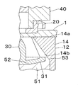
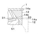
図10は、上述した下方ダイ10における下方ダイ本体11のみを別の下方ダイ本体51に置き換えた変形例を示し、下方ダイ本体51以外は図1等と同じ参照番号を用いる。下方ダイ本体51は、ボタン取付部材30のベース部31を載置するため、ベース部31の形状に合致するように上端面から下方に凹状に窪む上面52を有すると共に、周側面の上端部を、割型12の傾斜面14bと平行に斜めに面取りした周縁部53を含む。なお、本実施形態では、ベース部31は略円板状であるため、上面52は円形状となるが、これに限らず、例えばベース部が多角形状であれば上面52も多角形状となる。かかる変形例において、雌スナップ20の生地1への取り付け時に上方ダイ40によって雌スナップ20及び生地1を介して割型12が押し下げられると、図11の実線で示すように、割型12の傾斜面14bは下方ダイ本体51の周縁部53に対し滑って半径方向外側に変位する。割型12は、図11の破線で示す、最も半径方向外側の拡径位置まで移動可能であり、この拡径位置で生地支持面14aの半径方向内側端辺が下方ダイ本体51の周縁部53に接する。この割型12の拡径位置においてボタン取付部材30のベース部31が生地1を支持し、この状態でボタン取付部材30のポスト部32が上方ダイ40によって加締められる。
図12は割型の変形例を示す拡大図であり、割型62以外は図1等と同じ参照番号を用いる。割型62の生地支持面63の半径方向内側端部には微細な凹凸64が設けられる。凹凸64は、雌スナップ20の下面21’の突部26と共に、ポスト部32による生地1の貫通時に、雌スナップ20と割型62間を生地1が滑らないようにする滑り止めの役割を果たし、これによって生地1の張りが更に強化される。
1 生地
10 ボタン取付用下方ダイ
11、51 下方ダイ本体
12、62 割型
14 生地支持部
14a 生地支持面
14b 傾斜面
20 雌スナップ(ボタン)
21 底部
21’ (雌スナップの底部の)下面
24 突起受入部
25 取付用開口
30 ボタン取付部材
31 ベース部
31e ベース部の上方の周縁部(上縁)
32 ポスト部
32’ 先端
40 上方ダイ
53 周縁部
64 微細な凹凸
10 ボタン取付用下方ダイ
11、51 下方ダイ本体
12、62 割型
14 生地支持部
14a 生地支持面
14b 傾斜面
20 雌スナップ(ボタン)
21 底部
21’ (雌スナップの底部の)下面
24 突起受入部
25 取付用開口
30 ボタン取付部材
31 ベース部
31e ベース部の上方の周縁部(上縁)
32 ポスト部
32’ 先端
40 上方ダイ
53 周縁部
64 微細な凹凸
Claims (3)
- 板状のベース部(31)及びベース部(31)の中央から突出するポスト部(32)を有するボタン取付部材(30)の該ポスト部(32)を水平に配した生地(1)の下方から上方に貫通させ、次いでボタン(20)の取付用開口(25)に通した後、該ポスト部(32)を上方ダイ(40)で加締めることによってボタン(20)を生地(1)に取り付ける際に使用するボタン取付用下方ダイ(10)であって、
ボタン取付部材(30)が上面(11’、52)に載置される円柱状の下方ダイ本体(11、51)と、
下方ダイ本体(11、51)の周囲に複数配置され、前記上方ダイ(40)の相対的な下方への移動によってボタン(20)及び生地(1)を介して下方ダイ本体(11、51)に対し下方に押し下げられる割型(12、62)とを備え、
前記各割型(12、62)は、生地(1)の下面を支持する生地支持面(14a、63)を含み、
前記割型(12、62)は、前記ボタン取付部材(30)のポスト部(32)が生地(1)を貫通する時、前記生地支持面(14a、63)の少なくとも一部が、生地(1)の上面に接するボタン(20)の底面(21’)に上下方向において対応する生地(1)の下面におけるボタン底面対応範囲内に存在するオーバーラップ位置と、ポスト部(32)が生地(1)を貫通した後、前記生地支持面(14a、63)が前記ボタン底面対応範囲から外れる非オーバーラップ位置との間を半径方向に移動可能であるボタン取付用下方ダイ。 - 前記各割型(12、62)は、上方へと半径方向内側に傾斜する傾斜面(14b)を含み、
前記傾斜面(14b)は、割型(12、62)が下方ダイ本体(11、51)に対し押し下げられる際、前記下方ダイ本体(11、51)の周縁部(53)又は下方ダイ本体(11)に載置されたボタン取付部材(30)のベース部(31)の周縁部(31e)と係合して、割型(12、62)を前記オーバーラップ位置から非オーバーラップ位置へと変位させる請求項1のボタン取付用下方ダイ。 - 前記割型(12、62)は、前記生地支持面(14a、63)の半径方向内側端が前記下方ダイ本体(11、51)の周縁部(53)の半径方向位置又は下方ダイ本体(11)に載置されたボタン取付部材(30)のベース部(31)の周縁部(31e)の半径方向位置に来る拡径位置まで半径方向外側に移動可能である請求項2のボタン取付用下方ダイ。
Priority Applications (2)
| Application Number | Priority Date | Filing Date | Title |
|---|---|---|---|
| PCT/JP2010/057080 WO2011132278A1 (ja) | 2010-04-21 | 2010-04-21 | ボタン取付用下方ダイ |
| TW100111352A TW201201731A (en) | 2010-04-21 | 2011-03-31 | Lower die for attaching button |
Applications Claiming Priority (1)
| Application Number | Priority Date | Filing Date | Title |
|---|---|---|---|
| PCT/JP2010/057080 WO2011132278A1 (ja) | 2010-04-21 | 2010-04-21 | ボタン取付用下方ダイ |
Publications (1)
| Publication Number | Publication Date |
|---|---|
| WO2011132278A1 true WO2011132278A1 (ja) | 2011-10-27 |
Family
ID=44833836
Family Applications (1)
| Application Number | Title | Priority Date | Filing Date |
|---|---|---|---|
| PCT/JP2010/057080 Ceased WO2011132278A1 (ja) | 2010-04-21 | 2010-04-21 | ボタン取付用下方ダイ |
Country Status (2)
| Country | Link |
|---|---|
| TW (1) | TW201201731A (ja) |
| WO (1) | WO2011132278A1 (ja) |
Cited By (2)
| Publication number | Priority date | Publication date | Assignee | Title |
|---|---|---|---|---|
| JP2016079520A (ja) * | 2014-10-15 | 2016-05-16 | 香港多耐福有限公司Duraflex Hong Kong Limited | 樹脂リベット |
| CN106377016A (zh) * | 2016-11-15 | 2017-02-08 | 石狮市龙翔五金塑料制品有限公司 | 一种新型母扣组件及其生产工艺 |
Families Citing this family (3)
| Publication number | Priority date | Publication date | Assignee | Title |
|---|---|---|---|---|
| WO2013118262A1 (ja) * | 2012-02-08 | 2013-08-15 | Ykk株式会社 | ボタン取付装置及びボタン保持ダイ |
| WO2013150644A1 (ja) * | 2012-04-06 | 2013-10-10 | Ykk株式会社 | ボタン側ダイ、ボタン取付装置及びボタン取付方法 |
| WO2014061140A1 (ja) * | 2012-10-18 | 2014-04-24 | Ykk株式会社 | 支持ダイ、加締め判定方法、及びボタン取付具 |
Citations (6)
| Publication number | Priority date | Publication date | Assignee | Title |
|---|---|---|---|---|
| JPS5691320U (ja) * | 1979-12-13 | 1981-07-21 | ||
| JPS57121623U (ja) * | 1981-01-17 | 1982-07-28 | ||
| JPS6017105A (ja) * | 1983-07-11 | 1985-01-29 | スコービル・ジャパン株式会社 | 釦取付方法 |
| JPS6037019U (ja) * | 1983-08-15 | 1985-03-14 | 日本ノ−ション工業株式会社 | 加締装置 |
| EP0135885A2 (en) * | 1983-09-19 | 1985-04-03 | Nippon Notion Kogyo Co., Ltd. | Apparatus for attaching pairs of fastener elements onto garnment fabrics |
| JPS61167005A (ja) * | 1985-01-16 | 1986-07-28 | ウイリアム・プリム‐ヴエルケ・ゲゼルシヤフト・ミツト・ベシユレンクテル・ハフトウング・ウント・コンパニー・コマンデイートゲゼルシヤフト | 拘束機能を果たす機能部分を保持帯片に取り付ける鋲留めプレス |
-
2010
- 2010-04-21 WO PCT/JP2010/057080 patent/WO2011132278A1/ja not_active Ceased
-
2011
- 2011-03-31 TW TW100111352A patent/TW201201731A/zh unknown
Patent Citations (6)
| Publication number | Priority date | Publication date | Assignee | Title |
|---|---|---|---|---|
| JPS5691320U (ja) * | 1979-12-13 | 1981-07-21 | ||
| JPS57121623U (ja) * | 1981-01-17 | 1982-07-28 | ||
| JPS6017105A (ja) * | 1983-07-11 | 1985-01-29 | スコービル・ジャパン株式会社 | 釦取付方法 |
| JPS6037019U (ja) * | 1983-08-15 | 1985-03-14 | 日本ノ−ション工業株式会社 | 加締装置 |
| EP0135885A2 (en) * | 1983-09-19 | 1985-04-03 | Nippon Notion Kogyo Co., Ltd. | Apparatus for attaching pairs of fastener elements onto garnment fabrics |
| JPS61167005A (ja) * | 1985-01-16 | 1986-07-28 | ウイリアム・プリム‐ヴエルケ・ゲゼルシヤフト・ミツト・ベシユレンクテル・ハフトウング・ウント・コンパニー・コマンデイートゲゼルシヤフト | 拘束機能を果たす機能部分を保持帯片に取り付ける鋲留めプレス |
Cited By (2)
| Publication number | Priority date | Publication date | Assignee | Title |
|---|---|---|---|---|
| JP2016079520A (ja) * | 2014-10-15 | 2016-05-16 | 香港多耐福有限公司Duraflex Hong Kong Limited | 樹脂リベット |
| CN106377016A (zh) * | 2016-11-15 | 2017-02-08 | 石狮市龙翔五金塑料制品有限公司 | 一种新型母扣组件及其生产工艺 |
Also Published As
| Publication number | Publication date |
|---|---|
| TW201201731A (en) | 2012-01-16 |
Similar Documents
| Publication | Publication Date | Title |
|---|---|---|
| US10568395B2 (en) | Upper structure of female snap button, female snap button and method of attaching female snap button to texture | |
| CN102948946B (zh) | 钮扣安装用冲头、钮扣安装装置及钮扣安装方法 | |
| US20120180266A1 (en) | Button and Upper Die for Button Attachment | |
| JP3165574U (ja) | キーパッド用メタルドームスイッチ | |
| TW201201731A (en) | Lower die for attaching button | |
| JP5275476B2 (ja) | ボタン取付用上金型 | |
| JP2019526465A (ja) | 車両用シートカバーカールパンチシステム | |
| JP5275455B2 (ja) | ボタン取付部材 | |
| US7800581B2 (en) | User input device with self-centering flat spring | |
| JP2018086069A (ja) | 便座装置 | |
| JP5405133B2 (ja) | 視覚障害者誘導用のマット構造体 | |
| TWI500396B (zh) | Button mounting device and button retaining mold | |
| US2162731A (en) | Method of and apparatus for dieforming parts | |
| KR101745906B1 (ko) | 디스플레이 스탠드 베이스를 제조하기 위한 헤밍장치 | |
| JPH05177265A (ja) | プレス金型 | |
| JPWO2012004870A1 (ja) | 装飾部品及びその形成方法 | |
| JP2005314851A (ja) | 取着部材の外し力測定装置、および、挟持装置 | |
| JP6578488B1 (ja) | 打ち抜き装置 | |
| JP2001058219A (ja) | プレス金型 | |
| CN210747588U (zh) | 一种具有高强度的纽扣 | |
| CN104661549B (zh) | 纽扣安装方法和纽扣 | |
| CN103879216B (zh) | 一种压花装置及其使用方法 | |
| JP2002192251A (ja) | 深絞り成形型 | |
| JPWO2011118002A1 (ja) | ハトメ取付装置及びハトメ取付方法 | |
| CN107437473A (zh) | 薄型按键结构 |
Legal Events
| Date | Code | Title | Description |
|---|---|---|---|
| 121 | Ep: the epo has been informed by wipo that ep was designated in this application |
Ref document number: 10850220 Country of ref document: EP Kind code of ref document: A1 |
|
| NENP | Non-entry into the national phase |
Ref country code: DE |
|
| 122 | Ep: pct application non-entry in european phase |
Ref document number: 10850220 Country of ref document: EP Kind code of ref document: A1 |
|
| NENP | Non-entry into the national phase |
Ref country code: JP |