WO2011129340A1 - ミスト冷却装置及び熱処理装置 - Google Patents
ミスト冷却装置及び熱処理装置 Download PDFInfo
- Publication number
- WO2011129340A1 WO2011129340A1 PCT/JP2011/059105 JP2011059105W WO2011129340A1 WO 2011129340 A1 WO2011129340 A1 WO 2011129340A1 JP 2011059105 W JP2011059105 W JP 2011059105W WO 2011129340 A1 WO2011129340 A1 WO 2011129340A1
- Authority
- WO
- WIPO (PCT)
- Prior art keywords
- cooling
- cooling system
- workpiece
- pump
- mist
- Prior art date
- Legal status (The legal status is an assumption and is not a legal conclusion. Google has not performed a legal analysis and makes no representation as to the accuracy of the status listed.)
- Ceased
Links
Images



Classifications
-
- C—CHEMISTRY; METALLURGY
- C21—METALLURGY OF IRON
- C21D—MODIFYING THE PHYSICAL STRUCTURE OF FERROUS METALS; GENERAL DEVICES FOR HEAT TREATMENT OF FERROUS OR NON-FERROUS METALS OR ALLOYS; MAKING METAL MALLEABLE, e.g. BY DECARBURISATION OR TEMPERING
- C21D1/00—General methods or devices for heat treatment, e.g. annealing, hardening, quenching or tempering
- C21D1/62—Quenching devices
- C21D1/667—Quenching devices for spray quenching
-
- C—CHEMISTRY; METALLURGY
- C21—METALLURGY OF IRON
- C21D—MODIFYING THE PHYSICAL STRUCTURE OF FERROUS METALS; GENERAL DEVICES FOR HEAT TREATMENT OF FERROUS OR NON-FERROUS METALS OR ALLOYS; MAKING METAL MALLEABLE, e.g. BY DECARBURISATION OR TEMPERING
- C21D1/00—General methods or devices for heat treatment, e.g. annealing, hardening, quenching or tempering
- C21D1/74—Methods of treatment in inert gas, controlled atmosphere, vacuum or pulverulent material
-
- C—CHEMISTRY; METALLURGY
- C21—METALLURGY OF IRON
- C21D—MODIFYING THE PHYSICAL STRUCTURE OF FERROUS METALS; GENERAL DEVICES FOR HEAT TREATMENT OF FERROUS OR NON-FERROUS METALS OR ALLOYS; MAKING METAL MALLEABLE, e.g. BY DECARBURISATION OR TEMPERING
- C21D9/00—Heat treatment, e.g. annealing, hardening, quenching or tempering, adapted for particular articles; Furnaces therefor
- C21D9/0043—Muffle furnaces; Retort furnaces
-
- C—CHEMISTRY; METALLURGY
- C21—METALLURGY OF IRON
- C21D—MODIFYING THE PHYSICAL STRUCTURE OF FERROUS METALS; GENERAL DEVICES FOR HEAT TREATMENT OF FERROUS OR NON-FERROUS METALS OR ALLOYS; MAKING METAL MALLEABLE, e.g. BY DECARBURISATION OR TEMPERING
- C21D9/00—Heat treatment, e.g. annealing, hardening, quenching or tempering, adapted for particular articles; Furnaces therefor
- C21D9/0062—Heat-treating apparatus with a cooling or quenching zone
-
- F—MECHANICAL ENGINEERING; LIGHTING; HEATING; WEAPONS; BLASTING
- F27—FURNACES; KILNS; OVENS; RETORTS
- F27B—FURNACES, KILNS, OVENS OR RETORTS IN GENERAL; OPEN SINTERING OR LIKE APPARATUS
- F27B5/00—Muffle furnaces; Retort furnaces; Other furnaces in which the charge is held completely isolated
- F27B5/02—Muffle furnaces; Retort furnaces; Other furnaces in which the charge is held completely isolated of multiple-chamber type
-
- F—MECHANICAL ENGINEERING; LIGHTING; HEATING; WEAPONS; BLASTING
- F27—FURNACES; KILNS; OVENS; RETORTS
- F27D—DETAILS OR ACCESSORIES OF FURNACES, KILNS, OVENS OR RETORTS, IN SO FAR AS THEY ARE OF KINDS OCCURRING IN MORE THAN ONE KIND OF FURNACE
- F27D15/00—Handling or treating discharged material; Supports or receiving chambers therefor
- F27D15/02—Cooling
-
- F—MECHANICAL ENGINEERING; LIGHTING; HEATING; WEAPONS; BLASTING
- F27—FURNACES; KILNS; OVENS; RETORTS
- F27D—DETAILS OR ACCESSORIES OF FURNACES, KILNS, OVENS OR RETORTS, IN SO FAR AS THEY ARE OF KINDS OCCURRING IN MORE THAN ONE KIND OF FURNACE
- F27D7/00—Forming, maintaining or circulating atmospheres in heating chambers
- F27D7/02—Supplying steam, vapour, gases or liquids
-
- F—MECHANICAL ENGINEERING; LIGHTING; HEATING; WEAPONS; BLASTING
- F27—FURNACES; KILNS; OVENS; RETORTS
- F27D—DETAILS OR ACCESSORIES OF FURNACES, KILNS, OVENS OR RETORTS, IN SO FAR AS THEY ARE OF KINDS OCCURRING IN MORE THAN ONE KIND OF FURNACE
- F27D9/00—Cooling of furnaces or of charges therein
-
- F—MECHANICAL ENGINEERING; LIGHTING; HEATING; WEAPONS; BLASTING
- F27—FURNACES; KILNS; OVENS; RETORTS
- F27B—FURNACES, KILNS, OVENS OR RETORTS IN GENERAL; OPEN SINTERING OR LIKE APPARATUS
- F27B5/00—Muffle furnaces; Retort furnaces; Other furnaces in which the charge is held completely isolated
- F27B5/06—Details, accessories or equipment specially adapted for furnaces of these types
- F27B2005/062—Cooling elements
-
- F—MECHANICAL ENGINEERING; LIGHTING; HEATING; WEAPONS; BLASTING
- F27—FURNACES; KILNS; OVENS; RETORTS
- F27D—DETAILS OR ACCESSORIES OF FURNACES, KILNS, OVENS OR RETORTS, IN SO FAR AS THEY ARE OF KINDS OCCURRING IN MORE THAN ONE KIND OF FURNACE
- F27D9/00—Cooling of furnaces or of charges therein
- F27D2009/007—Cooling of charges therein
- F27D2009/0072—Cooling of charges therein the cooling medium being a gas
- F27D2009/0075—Cooling of charges therein the cooling medium being a gas in direct contact with the charge
-
- F—MECHANICAL ENGINEERING; LIGHTING; HEATING; WEAPONS; BLASTING
- F27—FURNACES; KILNS; OVENS; RETORTS
- F27D—DETAILS OR ACCESSORIES OF FURNACES, KILNS, OVENS OR RETORTS, IN SO FAR AS THEY ARE OF KINDS OCCURRING IN MORE THAN ONE KIND OF FURNACE
- F27D9/00—Cooling of furnaces or of charges therein
- F27D2009/007—Cooling of charges therein
- F27D2009/0081—Cooling of charges therein the cooling medium being a fluid (other than a gas in direct or indirect contact with the charge)
Definitions
- the present invention relates to a mist cooling device and a heat treatment device.
- Patent Document 1 discloses a mist cooling device that is used for heat treatment of an object to be processed such as metal and cools the object to be processed.
- the mist cooling device sprays a mist-like cooling liquid onto a heated object to be processed, and performs cooling using the latent heat of vaporization of the cooling liquid. Therefore, the mist cooling device has a higher cooling capacity than the conventional gas injection type cooling device. Further, by adjusting the amount of mist injection, it is possible to easily control the cooling rate of the object to be processed, which has been difficult with the conventional immersion type cooling apparatus.
- the mist cooling device since the heated workpiece is immersed in the coolant, the cooling is continued even if the device is stopped due to a power failure or the like. Therefore, the possibility that the apparatus is damaged by the heat of the workpiece is low.
- the coolant is caused to flow by a pump or the like, and the coolant is sprayed from the spray nozzle in a mist form. For this reason, when the apparatus stops due to a power failure or the like, the mist injection also stops, and the temperature and pressure inside the apparatus rise due to the heat of the object to be processed, which may damage the apparatus.
- the present invention has been made in consideration of the above points, and provides a mist cooling apparatus and a heat treatment apparatus that can prevent the apparatus from being damaged by the heat of the object to be processed in an emergency such as a power failure. Objective.
- a mist cooling device is driven by a nozzle for injecting a cooling liquid into a mist shape to a workpiece to be heated and provided in a cooling furnace, and driven toward the nozzle.
- a cooling system having a pump for flowing the cooling liquid; and a second cooling system that operates in response to the stop of the drive source and cools the workpiece.
- the second cooling system is activated and the cooling of the workpiece is continued.
- the pump may be driven by electric power
- the second cooling system may include an emergency power source that drives the pump in response to power supply stoppage.
- the pump is driven by the emergency power source and the cooling of the object to be processed is continued.
- the cooling system has a plurality of nozzles, and the second cooling system is provided between the pump and a nozzle located above the workpiece among the plurality of nozzles, and is in an open state at least when supply of power is stopped. You may have a valve. In this case, the valve is opened when the supply of power is stopped. Therefore, the cooling liquid is supplied into the cooling furnace from the nozzle located above the workpiece.
- the cooling system may have a plurality of pumps, and the emergency power source may drive a specific pump among the plurality of pumps.
- the specific pump is driven by the emergency power source to continue the cooling of the object to be processed. Therefore, the capacity of the emergency power supply can be limited to a capacity sufficient to drive a specific pump.
- a second cooling system provided above the cooling furnace for storing the cooling liquid; a second valve provided between the storage tank and the nozzle and opened at least when the drive source is stopped; You may have.
- the second valve is opened. Therefore, the cooling liquid is supplied into the cooling furnace through a nozzle from a storage tank provided above the cooling furnace.
- the cooling system may include a plurality of nozzles, and the second valve may be provided between the storage tank and a nozzle located above the object to be processed among the plurality of nozzles.
- the second valve is opened when the drive source is stopped. Therefore, the cooling liquid is supplied into the cooling furnace from the nozzle located above the workpiece.
- a heat treatment apparatus that performs heat treatment on an object to be processed may include the above-described mist cooling apparatus according to one embodiment of the present invention.
- the second cooling system is activated and the cooling of the workpiece is continued.
- the second cooling system is activated and the cooling of the object to be processed can be continued. For this reason, it is possible to prevent the apparatus from being damaged by the heat of the object to be processed in an emergency of stopping the drive source.
- FIG. 1 is an overall configuration diagram of a heat treatment apparatus 1 in the present embodiment.
- the heat treatment apparatus 1 performs heat treatment such as quenching on the workpiece M.
- the heat treatment apparatus 1 includes a heating chamber 2 and a cooling chamber (mist cooling device) 3.
- the heating chamber 2 and the cooling chamber 3 are disposed adjacent to each other.
- a partition wall 4 is provided between the heating chamber 2 and the cooling chamber 3. When the partition wall 4 is opened, the workpiece M heated in the heating chamber 2 is moved to the cooling chamber 3, and the workpiece M is cooled in the cooling chamber 3.
- the object to be processed M is subjected to heat treatment by the heat treatment apparatus 1.
- the workpiece M is made of a metal material (including an alloy) such as steel containing a predetermined amount of carbon.
- the workpiece M is shown in a rectangular parallelepiped shape. However, the workpiece M may be used in various shapes and sizes, the number of pieces to be processed at one time, and the like.
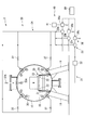
- FIG. 2 is a schematic view of the cooling chamber 3 in the present embodiment.
- the cooling chamber 3 in FIG. 2 is a cross-sectional view seen from the line AA in FIG.
- the cooling chamber 3 includes a container (cooling furnace) 10, a transfer unit 20, a cooling system 30, a second cooling system 40, and a control unit 50.
- the container 10 is an outer shell of the cooling chamber 3 and is a substantially cylindrical container capable of forming a sealed space inside.
- the container 10 is installed on the floor surface by a plurality of support legs 11.
- the conveyance unit 20 carries the workpiece M from the heating chamber 2 to the cooling chamber 3 and further carries it out of the cooling chamber 3.
- the transport unit 20 transports the workpiece M in a direction parallel to the central axis of the container 10.
- the transport unit 20 includes a pair of support frames 21, a plurality of transport rollers 22, and a drive unit (not shown).
- the pair of support frames 21 are erected on the bottom inside the container 10 and support the workpiece M from below through a plurality of transport rollers 22.
- the pair of support frames 21 are provided to extend in the conveyance direction of the workpiece M.
- the plurality of transport rollers 22 smoothly transport the workpiece M by rotating.
- the plurality of transport rollers 22 are provided on the mutually opposing surfaces of the pair of support frames 21 so as to be rotatable at a predetermined interval in the transport direction.
- a drive unit (not shown) rotates the conveyance roller 22.
- the workpiece M of this embodiment is not placed directly on the transport roller 22 but is placed on the transport roller 22 via the tray 23.
- the cooling system 30 cools the workpiece M by spraying a cooling liquid in a mist form on the workpiece M that is heated and provided in the container 10.
- the cooling system 30 includes a recovery pipe 31, a heat exchanger 32, a pump 33, a supply pipe 34, and a nozzle 35.
- a cooling liquid to be used for example, water, oil, salt, a fluorine-based inert liquid, or the like is used.
- the recovery pipe 31 is a pipe member that recovers the cooling liquid supplied into the container 10. Note that the cooling liquid when being recovered in the recovery pipe 31 is heated by the heat of the workpiece M.
- the heat exchanger 32 cools the recovered cooling liquid.
- the pump 33 discharges the cooling liquid recovered from the container 10 and introduced into the recovery pipe 31 to the supply pipe 34 and flows toward the nozzle 35.
- a plurality of pumps 33 of the present embodiment are used, and three pumps, a first pump (specific pump) 33a, a second pump 33b, and a third pump 33c, are provided.
- the first pump 33 a, the second pump 33 b and the third pump 33 c are arranged in parallel with the supply pipe 34.
- the inverters 36 are connected to the plurality of pumps 33, respectively. That is, the first inverter 33a, the second inverter 36b, and the third inverter 36c are connected to the first pump 33a, the second pump 33b, and the third pump 33c, respectively.
- the inverter 36 drives the pump 33 in accordance with a control instruction from the control unit 50 described later.
- the drive source of the pump 33 is electric power E, and the electric power E is supplied to the inverter 36.
- the supply pipe 34 is a pipe member that once collects the cooling liquid discharged from the plurality of pumps 33 and then supplies the liquid to a plurality of nozzles 35 to be described later.
- the nozzle 35 cools the workpiece M by spraying a cooling liquid in a mist form on the workpiece M provided in the container 10 by being heated.
- a plurality of nozzles 35 are provided on the inner wall of the container 10 so as to surround the workpiece M. For this reason, the part which the mist does not hit in the to-be-processed object M decreases, the to-be-processed object M can be cooled uniformly, and generation
- a portion of the supply pipe 34 connected to the plurality of nozzles 35 is provided with a plurality of valves 37.
- the valve 37 is a normally closed type valve that is operated by the electric power E and is closed when the supply of the electric power E is stopped.
- an emergency valve 37A is provided in a portion of the supply pipe 34 connected to the upper nozzle 35A.
- the emergency valve 37A is operated by the electric power E, but unlike the valve 37, the emergency valve 37A is a normal open type valve that is opened when the supply of the electric power E is stopped.
- the second cooling system 40 cools the workpiece M by supplying a cooling liquid to the heated workpiece M when the supply of the electric power E that drives the cooling system 30 is stopped.
- the second cooling system 40 includes a battery (emergency power supply) 41 and an emergency valve 37A.
- the battery 41 is connected only to the first inverter 36a, and is a drive source that drives only the first pump 33a in the event of an emergency such as stopping the supply of electric power E.
- an emergency power supply device using an internal combustion engine or the like may be used.
- the control unit 50 controls the drive of the pump 33 via the inverter 36.
- the control unit 50 can individually control the driving of the plurality of pumps 33 and can drive only a specific pump 33. Since the control unit 50 is driven by the electric power E, when the control unit 50 needs to control the driving of the first pump 33a when the supply of the electric power E is stopped, the electric power of the battery 41 is supplied to the control unit 50. Also good.
- the cooling operation for the workpiece M in the cooling chamber 3 in this embodiment will be described.
- the cooling operation for the workpiece M of the cooling system 30 will be described with reference to FIGS. 1 and 2.
- the workpiece M is heated in the heating chamber 2.
- the partition wall 4 is opened, and the workpiece M heated by the driving of the transport unit 20 is carried into the cooling chamber 3.
- the cooling system 30 After completion of the delivery to the cooling chamber 3, the cooling system 30 starts cooling the workpiece M.
- the controller 50 controls the driving of the pump 33 via the inverter 36 and the cooling liquid is discharged to the supply pipe 34.
- the cooling liquid flows in the supply pipe 34 toward the nozzle 35 and is jetted from the nozzle 35 toward the workpiece M in a mist form.
- the mist adhering to the heated workpiece M is vaporized while taking the latent heat of vaporization from the workpiece M.
- the latent heat of vaporization of the cooling liquid the workpiece M can be quickly cooled.
- the vaporized cooling liquid is liquefied again by a liquefaction trap (not shown) and flows into the recovery pipe 31.
- the cooling liquid flowing in the recovery pipe 31 is cooled by the heat exchanger 32 and discharged again to the supply pipe 34 by the pump 33.
- the cooling liquid circulates and flows in the cooling system 30, the workpiece M can be continuously cooled.
- FIG. 3 is a schematic diagram showing the operation of the second cooling system 40 in the present embodiment. Note that, in the recovery pipe 31 and the supply pipe 34 shown in FIG. 3, only the portion where the cooling liquid flows is indicated by a bold line.
- the second pump 33b and the third pump 33c are stopped.
- a battery 41 is connected to the first inverter 36a connected to the first pump 33a. Therefore, even if the supply of the electric power E is stopped, the first pump 33a can be driven by the electric power supplied from the battery 41. Further, since the battery 41 only drives the first pump 33a, the capacity of the battery 41 can be limited to a capacity sufficient to drive the first pump 33a, and the second cooling system 40 is installed. Cost can be reduced.
- the first pump 33a continues to be driven by the power supply from the battery 41. Since the plurality of valves 37 provided in the supply pipe 34 are normally closed type valves, they are all closed when the supply of the electric power E is stopped. Therefore, the flow of the cooling liquid toward the nozzle 35 is blocked by the valve 37, and the supply of the cooling liquid from the nozzle 35 is stopped.
- the emergency valve 37A is a normally open type valve
- the emergency valve 37A is opened when the supply of the electric power E is stopped. That is, the cooling liquid is supplied only from the supply pipe 34 to the upper nozzle 35A through the emergency valve 37A.
- the cooling liquid is supplied only from a specific upper nozzle 35A among a plurality of nozzles provided in the cooling chamber 3, even when the battery 41 drives only the first pump 33a, the mist is discharged from the upper nozzle 35A.
- the pressure required for jetting can be applied to the cooling liquid, and the cooling liquid can be jetted in a sufficiently mist form from the upper nozzle 35A.
- the upper nozzle 35A is provided on the upper side in the vertical direction of the workpiece M, the cooling liquid can be reliably supplied to the workpiece M even when the flow rate of the cooling liquid is small. Therefore, the cooling liquid is supplied from the upper nozzle 35 ⁇ / b> A toward the workpiece M, and the cooling of the heated workpiece M is continued.
- the present embodiment since the supply of the electric power E is stopped and the cooling of the workpiece M by the cooling system 30 is stopped, the second cooling system 40 is activated to continue the cooling of the workpiece M. it can. Therefore, it is possible to prevent the cooling chamber 3 from being damaged by the heat of the workpiece M during an emergency of stopping the supply of the electric power E.
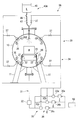
- FIG. 4 is a schematic view of the cooling chamber 3A in the present embodiment. Note that the cooling chamber 3A in FIG. 4 is a cross-sectional view taken along line AA in FIG. In FIG. 4, the same components as those of the first embodiment shown in FIG. 2 are denoted by the same reference numerals, and the description thereof is omitted.
- the cooling chamber (mist cooling device) 3A of the present embodiment is provided in the heat treatment device 1 as in the first embodiment.
- the supply pipe 34 connected to the upper nozzle 35A is provided with a normally closed type valve 37.
- the cooling chamber 3A has a second cooling system 40A.
- the second cooling system 40A continues to cool the workpiece M when the supply of the electric power E to the cooling system 30 is stopped.
- the second cooling system 40 ⁇ / b> A includes a storage tank 45, a second supply pipe 46, and a second emergency valve 47.
- the storage tank 45 is a tank that stores the second cooling liquid (cooling fluid) L therein.
- the storage tank 45 is provided above the container 10 in the cooling chamber 3A.
- As the second cooling liquid L water or the like is used.
- the second supply pipe 46 is a pipe member that is arranged in parallel with the valve 37 corresponding to the upper nozzle 35 ⁇ / b> A and connects the upper nozzle 35 ⁇ / b> A and the storage tank 45.
- the second emergency valve 47 is provided in the second supply pipe 46.
- the second emergency valve 47 is a normally open type valve that is opened when the supply of electric power E is stopped.
- the second emergency valve 47 is normally closed while the electric power E is supplied.
- FIG. 5 is a schematic diagram showing the operation of the second cooling system 40A in the present embodiment. Note that, in the supply pipe 34 and the second supply pipe 46 illustrated in FIG. 5, only a portion where the second cooling liquid L flows is indicated by a bold line.
- All the valves 37 provided in the supply pipe 34 are closed when the supply of the electric power E is stopped. That is, in the present embodiment, the cooling liquid does not flow in the cooling system 30 when the supply of the electric power E is stopped.
- the second emergency valve 47 is opened when the supply of the electric power E is stopped. Therefore, the second cooling liquid L flows from the storage tank 45 toward the upper nozzle 35A via the second supply pipe 46, and the second cooling liquid L is supplied from the upper nozzle 35A toward the workpiece M.
- the second cooling system 40A is driven. No drive source is required to
- the second cooling liquid L in the storage tank 45 since the second cooling liquid L in the storage tank 45 is discharged from the upper nozzle 35A using the height difference, the pressure necessary to inject mist from the upper nozzle 35A is set to the second pressure.
- the cooling liquid L may not be added, and the second cooling liquid L may not be ejected in a mist form.
- the upper nozzle 35A is provided above the workpiece M in the vertical direction, the second cooling liquid L can be reliably supplied to the workpiece M. Therefore, the second cooling liquid L is supplied from the upper nozzle 35 ⁇ / b> A toward the workpiece M, and cooling of the heated workpiece M is continued.
- the present embodiment even when the supply of the electric power E is stopped and the cooling of the workpiece M by the cooling system 30 is stopped, the second cooling system 40A is operated to continue the cooling of the workpiece M. it can. Therefore, it is possible to prevent the cooling chamber 3 ⁇ / b> A from being damaged by the heat of the workpiece M in an emergency of stopping the supply of the electric power E.
- the type of the drive source of the cooling system 30 is not limited, a drive source other than the electric power E may be used.
- a drive source other than the electric power E may be used.
- an apparatus using an internal combustion engine or the like in which the pump of the cooling system 30 is driven using fuel or the like as a drive source may be used, and the second cooling system 40A may be activated when the supply of fuel or the like is stopped.
- the second cooling system 40A when the second cooling system 40A is activated, not only when the supply of the drive source is stopped, but also the recovery pipe 31 or the supply pipe 34 of the cooling system 30 is damaged as long as the second supply pipe 46 is not damaged. Sometimes, the second cooling system 40A may be activated.
- the second emergency valve 47 is a normally open type valve, the supply to the workpiece M is not stopped until the second cooling liquid L in the storage tank 45 is exhausted. Therefore, a device for measuring the water level of the second cooling liquid L supplied into the container 10 may be provided, and the second emergency valve 47 may be closed when a certain water level is reached. In this case, a driving source (battery or the like) for driving the water level measuring instrument and the second emergency valve 47 is required.
- Cooling apparatus 3A ... Cooling chamber (mist cooling device) 10 ... Container (cooling furnace) 30 ... Cooling system 33 ... Pump 33a ... First pump (specific pump) 35 ... Nozzle 35A ... Upper nozzle 37A ... Emergency valve 40, 40A ... Second cooling system 41 ... Battery (emergency power supply) 45 ... Reservoir 47 ... Second emergency valve M ... Object L ... Second cooling liquid (cooling fluid) E ... Electric power (drive source)
Landscapes
- Engineering & Computer Science (AREA)
- Chemical & Material Sciences (AREA)
- Mechanical Engineering (AREA)
- General Engineering & Computer Science (AREA)
- Physics & Mathematics (AREA)
- Thermal Sciences (AREA)
- Crystallography & Structural Chemistry (AREA)
- Materials Engineering (AREA)
- Metallurgy (AREA)
- Organic Chemistry (AREA)
- Heat Treatments In General, Especially Conveying And Cooling (AREA)
- Furnace Details (AREA)
Abstract
Description
本発明の一態様によれば、ミスト冷却装置は、加熱されて冷却炉内に設けられた被処理物に対して冷却用液体をミスト状に噴射するノズルと駆動源によって駆動されノズルに向けて冷却用液体を流動させるポンプとを有する冷却システムと、駆動源の停止に応じて作動し、被処理物を冷却する第2冷却システムとを備える。
本発明の一態様によれば、駆動源が停止し冷却システムによる被処理物に対する冷却が停止すると、第2冷却システムが作動して被処理物に対する冷却が続行される。
この場合には、電力の供給が停止し冷却システムによる被処理物に対する冷却が停止すると、非常用電源によってポンプが駆動されて被処理物に対する冷却が続行される。
この場合には、電力の供給が停止すると上記バルブは開状態となる。そのため、被処理物の上側に位置するノズルから冷却用液体が冷却炉内に供給される。
この場合には、電力の供給が停止し冷却システムによる被処理物に対する冷却が停止すると、非常用電源によって特定のポンプが駆動されて被処理物に対する冷却が続行される。そのため、非常用電源の容量を特定のポンプを駆動させるに十分な容量に限定することが可能となる。
この場合には、駆動源が停止し冷却システムによる被処理物に対する冷却が停止すると、第2バルブが開状態となる。そのため、冷却炉より上側に設けられる貯留槽からノズルを介して冷却用液体が冷却炉内に供給される。
この場合には、駆動源が停止すると第2バルブは開状態となる。そのため、被処理物の上側に位置するノズルから冷却用液体が冷却炉内に供給される。
この場合には、駆動源が停止し冷却システムによる被処理物に対する冷却が停止すると、第2冷却システムが作動して被処理物に対する冷却が続行される。
図1は、本実施形態における熱処理装置1の全体構成図である。
熱処理装置1は、被処理物Mに対して焼き入れ等の熱処理を施す。熱処理装置1は、加熱室2と、冷却室(ミスト冷却装置)3とを有している。加熱室2と冷却室3とは、隣接して配置されている。加熱室2と冷却室3との間には隔壁4が設けられている。隔壁4の開放時に、加熱室2において加熱された被処理物Mを冷却室3へ移動させ、冷却室3内で被処理物Mを冷却する。
図2は、本実施形態における冷却室3の概略図である。なお、図2における冷却室3は、図1のA-A線から見た断面図である。
容器10は、冷却室3の外殻であり、内部に密閉した空間を形成可能な略円筒状の容器である。容器10は、複数の支持脚11によって床面に設置されている。
なお、使用される冷却用液体としては、例えば水、油、ソルト又はフッ素系不活性液体等が用いられる。
まず、冷却システム30の被処理物Mに対する冷却動作を、図1及び図2を参照して説明する。
被処理物Mは加熱室2において加熱される。加熱室2における加熱が終了した後、隔壁4が開放され、搬送部20の駆動により加熱された被処理物Mが冷却室3内に搬入される。
冷却システム30内を冷却用液体が循環して流動することで、被処理物Mを継続的に冷却することができる。
図3は、本実施形態における第2冷却システム40の動作を示す概略図である。なお、図3に示す回収管31及び供給管34において、冷却用液体が流動する部分のみを太線で表している。
本実施形態によれば、電力Eの供給が停止し冷却システム30による被処理物Mに対する冷却が停止しても、第2冷却システム40が作動して被処理物Mに対する冷却を続行することができる。そのため、電力Eの供給停止という非常時において、被処理物Mの熱によって冷却室3が破損することを防止できる。
本実施形態における冷却室3Aを、図4を参照して説明する。
図4は、本実施形態における冷却室3Aの概略図である。なお、図4における冷却室3Aは、図1のA-A線から見た断面図である。また、図4において、図2に示す第1の実施形態の構成要素と同一の要素については同一の符号を付し、その説明を省略する。
本実施形態によれば、電力Eの供給が停止し冷却システム30による被処理物Mに対する冷却が停止しても、第2冷却システム40Aが作動して被処理物Mに対する冷却を続行することができる。そのため、電力Eの供給停止という非常時において、被処理物Mの熱によって冷却室3Aが破損することを防止できる。
3,3A…冷却室(ミスト冷却装置)
10…容器(冷却炉)
30…冷却システム
33…ポンプ
33a…第1ポンプ(特定のポンプ)
35…ノズル
35A…上側ノズル
37A…非常用バルブ
40,40A…第2冷却システム
41…バッテリー(非常用電源)
45…貯留槽
47…第2非常用バルブ
M…被処理物
L…第2冷却用液体(冷却用流体)
E…電力(駆動源)
Claims (8)
- 加熱されて冷却炉内に設けられた被処理物に対して冷却用液体をミスト状に噴射するノズルと、駆動源によって駆動され前記ノズルに向けて冷却用液体を流動させるポンプとを有する冷却システムを備えたミスト冷却装置であって、
前記駆動源の停止に応じて作動し、前記被処理物を冷却する第2冷却システムを備えるミスト冷却装置。 - 前記ポンプは、電力によって駆動され、
前記第2冷却システムは、前記電力の供給停止に応じて前記ポンプを駆動させる非常用電源を有する請求項1に記載のミスト冷却装置。 - 前記冷却システムは、前記ノズルを複数有し、
前記第2冷却システムは、前記ポンプと複数の前記ノズルのうち前記被処理物の上側に位置するノズルとの間に設けられ且つ少なくとも前記電力の供給停止中に開状態となるバルブを有する請求項2に記載のミスト冷却装置。 - 前記冷却システムは、前記ポンプを複数有し、
前記非常用電源は、複数の前記ポンプのうち特定のポンプを駆動させる請求項2に記載のミスト冷却装置。 - 前記冷却システムは、前記ポンプを複数有し、
前記非常用電源は、複数の前記ポンプのうち特定のポンプを駆動させる請求項3に記載のミスト冷却装置。 - 前記第2冷却システムは、
前記冷却炉より上側に設けられ、冷却用液体を貯留する貯留槽と、
前記貯留槽と前記ノズルとの間に設けられ、少なくとも前記駆動源の停止中に開状態となる第2バルブとを有する請求項1に記載のミスト冷却装置。 - 前記冷却システムは、前記ノズルを複数有し、
前記第2バルブは、前記貯留槽と複数の前記ノズルのうち前記被処理物の上側に位置するノズルとの間に設けられている請求項6に記載のミスト冷却装置。 - 被処理物に対して熱処理を行う熱処理装置であって、
請求項1から7のいずれか一項に記載のミスト冷却装置を有する熱処理装置。
Priority Applications (2)
| Application Number | Priority Date | Filing Date | Title |
|---|---|---|---|
| CN201180019045.8A CN102918347B (zh) | 2010-04-12 | 2011-04-12 | 喷雾冷却装置及热处理装置 |
| US13/640,135 US9359654B2 (en) | 2010-04-12 | 2011-04-12 | Mist cooling apparatus and heat treatment apparatus |
Applications Claiming Priority (2)
| Application Number | Priority Date | Filing Date | Title |
|---|---|---|---|
| JP2010-091362 | 2010-04-12 | ||
| JP2010091362A JP5478340B2 (ja) | 2010-04-12 | 2010-04-12 | ミスト冷却装置及び熱処理装置 |
Publications (1)
| Publication Number | Publication Date |
|---|---|
| WO2011129340A1 true WO2011129340A1 (ja) | 2011-10-20 |
Family
ID=44798711
Family Applications (1)
| Application Number | Title | Priority Date | Filing Date |
|---|---|---|---|
| PCT/JP2011/059105 Ceased WO2011129340A1 (ja) | 2010-04-12 | 2011-04-12 | ミスト冷却装置及び熱処理装置 |
Country Status (4)
| Country | Link |
|---|---|
| US (1) | US9359654B2 (ja) |
| JP (1) | JP5478340B2 (ja) |
| CN (1) | CN102918347B (ja) |
| WO (1) | WO2011129340A1 (ja) |
Cited By (4)
| Publication number | Priority date | Publication date | Assignee | Title |
|---|---|---|---|---|
| CN102816907A (zh) * | 2012-08-03 | 2012-12-12 | 无锡市绿色热处理设备有限公司 | 一种可控喷淋淬火机 |
| WO2016013428A1 (ja) * | 2014-07-25 | 2016-01-28 | 株式会社Ihi | 冷却装置及び多室型熱処理装置 |
| US9617611B2 (en) | 2011-03-28 | 2017-04-11 | Ipsen, Inc. | Quenching process and apparatus for practicing said process |
| EP3364137A4 (en) * | 2015-10-15 | 2019-03-06 | Toyoda Iron Works Co., Ltd. | HEATER |
Families Citing this family (3)
| Publication number | Priority date | Publication date | Assignee | Title |
|---|---|---|---|---|
| JP5588661B2 (ja) * | 2009-12-11 | 2014-09-10 | 株式会社Ihi | ミスト冷却装置及び熱処理装置 |
| CN105228421B (zh) * | 2015-10-30 | 2018-01-23 | 江苏同盛环保技术有限公司 | 一种用于电子设备的微雾冷却装置 |
| CN105953603A (zh) * | 2016-06-25 | 2016-09-21 | 湖北长平汽车装备有限公司 | 一种数控喷淋系统 |
Citations (3)
| Publication number | Priority date | Publication date | Assignee | Title |
|---|---|---|---|---|
| JPS5792733U (ja) * | 1980-11-20 | 1982-06-08 | ||
| JP2005074355A (ja) * | 2003-09-02 | 2005-03-24 | Taiheiyo Cement Corp | 排ガス冷却用散水システム |
| WO2010005083A1 (ja) * | 2008-07-10 | 2010-01-14 | 株式会社Ihi | 熱処理装置 |
Family Cites Families (8)
| Publication number | Priority date | Publication date | Assignee | Title |
|---|---|---|---|---|
| US3300198A (en) * | 1963-12-27 | 1967-01-24 | Olin Mathieson | Apparatus for quenching metal |
| US4024903A (en) * | 1974-05-20 | 1977-05-24 | Nippon Kokan Kabushiki Kaisha | Evaporative cooling method by natural circulation of cooling water |
| JPS5937143B2 (ja) | 1976-11-25 | 1984-09-07 | 日立造船株式会社 | 連続鋳造設備における水量調節バルブ |
| JPS5792733A (en) | 1980-11-29 | 1982-06-09 | Matsushita Electric Works Ltd | Circuit breaker |
| JPH073314B2 (ja) * | 1988-03-07 | 1995-01-18 | イーグル工業株式会社 | 真空熱処理炉の非常用冷却装置 |
| JPH0645997B2 (ja) * | 1988-03-09 | 1994-06-15 | 株式会社フジタ | シールド掘削機後方の地盤沈下防止装置 |
| JPH11153386A (ja) | 1997-11-25 | 1999-06-08 | Ishikawajima Harima Heavy Ind Co Ltd | 多室式マルチ冷却真空炉 |
| CN201111966Y (zh) * | 2007-09-30 | 2008-09-10 | 中国原子能科学研究院 | 钠冷快堆钠循环泵的水冷却系统 |
-
2010
- 2010-04-12 JP JP2010091362A patent/JP5478340B2/ja not_active Expired - Fee Related
-
2011
- 2011-04-12 WO PCT/JP2011/059105 patent/WO2011129340A1/ja not_active Ceased
- 2011-04-12 CN CN201180019045.8A patent/CN102918347B/zh not_active Expired - Fee Related
- 2011-04-12 US US13/640,135 patent/US9359654B2/en active Active
Patent Citations (3)
| Publication number | Priority date | Publication date | Assignee | Title |
|---|---|---|---|---|
| JPS5792733U (ja) * | 1980-11-20 | 1982-06-08 | ||
| JP2005074355A (ja) * | 2003-09-02 | 2005-03-24 | Taiheiyo Cement Corp | 排ガス冷却用散水システム |
| WO2010005083A1 (ja) * | 2008-07-10 | 2010-01-14 | 株式会社Ihi | 熱処理装置 |
Cited By (8)
| Publication number | Priority date | Publication date | Assignee | Title |
|---|---|---|---|---|
| US9617611B2 (en) | 2011-03-28 | 2017-04-11 | Ipsen, Inc. | Quenching process and apparatus for practicing said process |
| CN102816907A (zh) * | 2012-08-03 | 2012-12-12 | 无锡市绿色热处理设备有限公司 | 一种可控喷淋淬火机 |
| CN102816907B (zh) * | 2012-08-03 | 2013-11-06 | 无锡市绿色热处理设备有限公司 | 一种可控喷淋淬火机 |
| WO2016013428A1 (ja) * | 2014-07-25 | 2016-01-28 | 株式会社Ihi | 冷却装置及び多室型熱処理装置 |
| JP2016029203A (ja) * | 2014-07-25 | 2016-03-03 | 株式会社Ihi | 冷却装置及び多室型熱処理装置 |
| US10273553B2 (en) | 2014-07-25 | 2019-04-30 | Ihi Corporation | Cooling device and multi-chamber heat treatment device |
| EP3364137A4 (en) * | 2015-10-15 | 2019-03-06 | Toyoda Iron Works Co., Ltd. | HEATER |
| US10612853B2 (en) | 2015-10-15 | 2020-04-07 | Toyoda Iron Works Co., Ltd. | Heating device |
Also Published As
| Publication number | Publication date |
|---|---|
| CN102918347A (zh) | 2013-02-06 |
| US9359654B2 (en) | 2016-06-07 |
| US20130032977A1 (en) | 2013-02-07 |
| JP2011220627A (ja) | 2011-11-04 |
| JP5478340B2 (ja) | 2014-04-23 |
| CN102918347B (zh) | 2015-09-30 |
Similar Documents
| Publication | Publication Date | Title |
|---|---|---|
| JP5478340B2 (ja) | ミスト冷却装置及び熱処理装置 | |
| US9187795B2 (en) | Mist cooling apparatus, heat treatment apparatus, and mist cooling method | |
| TW202100249A (zh) | 基板處理裝置及基板處理方法 | |
| JPWO2016080197A1 (ja) | 熱処理装置及び冷却装置 | |
| CN102822357A (zh) | 热处理方法 | |
| KR101538932B1 (ko) | 방사성 물질 저감 설비 및 이를 구비하는 원전 | |
| JP2015049164A (ja) | 原子炉圧力容器の除染方法及びその除染システム | |
| CN111906102B (zh) | 清洗腔室及清洗设备 | |
| JP2012207306A (ja) | 焼入れ方法及び同方法を実施するための装置 | |
| JP2019178954A (ja) | 海水冷却システム | |
| US20150075572A1 (en) | Cleaning device of porous plate for nuclear power | |
| KR101502395B1 (ko) | 피동 격납부 살수 및 냉각계통, 및 이를 구비하는 원전 | |
| JP2010012417A (ja) | 洗浄装置及び洗浄方法 | |
| JP2007023962A (ja) | 軸流排気式蒸気タービン装置 | |
| KR20160032966A (ko) | 이물질 제거장치 | |
| JP6414959B2 (ja) | 熱処理装置 | |
| KR20200092704A (ko) | 피도금체 내부 도금 장치 및 방법 | |
| JP6346447B2 (ja) | 基板処理装置 | |
| JP3154220U (ja) | コンクリートミキサー車の車台上に回転自在に設けられたミキサードラム内の生コンクリートの温度が35℃を超えないように維持するための温度維持装置 | |
| CN104251644A (zh) | 一种工业列管式水冷却器在线精确化学清垢装置及方法 | |
| JP4970962B2 (ja) | 気化冷却装置 | |
| KR101299338B1 (ko) | 산세 탱크용 가스 배출 장치 | |
| KR20120057317A (ko) | 진공 장치 및 이를 구비한 진공 탈가스 설비 | |
| JP2018012863A (ja) | 航空部品の焼入れ装置及び熱処理システム | |
| JP2008196814A (ja) | 気化冷却装置 |
Legal Events
| Date | Code | Title | Description |
|---|---|---|---|
| WWE | Wipo information: entry into national phase |
Ref document number: 201180019045.8 Country of ref document: CN |
|
| 121 | Ep: the epo has been informed by wipo that ep was designated in this application |
Ref document number: 11768861 Country of ref document: EP Kind code of ref document: A1 |
|
| WWE | Wipo information: entry into national phase |
Ref document number: 13640135 Country of ref document: US |
|
| NENP | Non-entry into the national phase |
Ref country code: DE |
|
| WWE | Wipo information: entry into national phase |
Ref document number: 9171/DELNP/2012 Country of ref document: IN |
|
| 122 | Ep: pct application non-entry in european phase |
Ref document number: 11768861 Country of ref document: EP Kind code of ref document: A1 |