WO2011129255A1 - 蛍光観察装置および蛍光画像処理方法 - Google Patents
蛍光観察装置および蛍光画像処理方法 Download PDFInfo
- Publication number
- WO2011129255A1 WO2011129255A1 PCT/JP2011/058780 JP2011058780W WO2011129255A1 WO 2011129255 A1 WO2011129255 A1 WO 2011129255A1 JP 2011058780 W JP2011058780 W JP 2011058780W WO 2011129255 A1 WO2011129255 A1 WO 2011129255A1
- Authority
- WO
- WIPO (PCT)
- Prior art keywords
- image
- fluorescence
- white light
- unit
- displacement amount
- Prior art date
- Legal status (The legal status is an assumption and is not a legal conclusion. Google has not performed a legal analysis and makes no representation as to the accuracy of the status listed.)
- Ceased
Links
Images




Classifications
-
- A—HUMAN NECESSITIES
- A61—MEDICAL OR VETERINARY SCIENCE; HYGIENE
- A61B—DIAGNOSIS; SURGERY; IDENTIFICATION
- A61B1/00—Instruments for performing medical examinations of the interior of cavities or tubes of the body by visual or photographical inspection, e.g. endoscopes; Illuminating arrangements therefor
- A61B1/04—Instruments for performing medical examinations of the interior of cavities or tubes of the body by visual or photographical inspection, e.g. endoscopes; Illuminating arrangements therefor combined with photographic or television appliances
- A61B1/05—Instruments for performing medical examinations of the interior of cavities or tubes of the body by visual or photographical inspection, e.g. endoscopes; Illuminating arrangements therefor combined with photographic or television appliances characterised by the image sensor, e.g. camera, being in the distal end portion
-
- A—HUMAN NECESSITIES
- A61—MEDICAL OR VETERINARY SCIENCE; HYGIENE
- A61B—DIAGNOSIS; SURGERY; IDENTIFICATION
- A61B1/00—Instruments for performing medical examinations of the interior of cavities or tubes of the body by visual or photographical inspection, e.g. endoscopes; Illuminating arrangements therefor
- A61B1/00002—Operational features of endoscopes
- A61B1/00004—Operational features of endoscopes characterised by electronic signal processing
- A61B1/00009—Operational features of endoscopes characterised by electronic signal processing of image signals during a use of endoscope
- A61B1/000095—Operational features of endoscopes characterised by electronic signal processing of image signals during a use of endoscope for image enhancement
-
- A—HUMAN NECESSITIES
- A61—MEDICAL OR VETERINARY SCIENCE; HYGIENE
- A61B—DIAGNOSIS; SURGERY; IDENTIFICATION
- A61B1/00—Instruments for performing medical examinations of the interior of cavities or tubes of the body by visual or photographical inspection, e.g. endoscopes; Illuminating arrangements therefor
- A61B1/04—Instruments for performing medical examinations of the interior of cavities or tubes of the body by visual or photographical inspection, e.g. endoscopes; Illuminating arrangements therefor combined with photographic or television appliances
- A61B1/043—Instruments for performing medical examinations of the interior of cavities or tubes of the body by visual or photographical inspection, e.g. endoscopes; Illuminating arrangements therefor combined with photographic or television appliances for fluorescence imaging
-
- A—HUMAN NECESSITIES
- A61—MEDICAL OR VETERINARY SCIENCE; HYGIENE
- A61B—DIAGNOSIS; SURGERY; IDENTIFICATION
- A61B5/00—Measuring for diagnostic purposes; Identification of persons
- A61B5/0059—Measuring for diagnostic purposes; Identification of persons using light, e.g. diagnosis by transillumination, diascopy, fluorescence
- A61B5/0071—Measuring for diagnostic purposes; Identification of persons using light, e.g. diagnosis by transillumination, diascopy, fluorescence by measuring fluorescence emission
-
- A—HUMAN NECESSITIES
- A61—MEDICAL OR VETERINARY SCIENCE; HYGIENE
- A61B—DIAGNOSIS; SURGERY; IDENTIFICATION
- A61B5/00—Measuring for diagnostic purposes; Identification of persons
- A61B5/0059—Measuring for diagnostic purposes; Identification of persons using light, e.g. diagnosis by transillumination, diascopy, fluorescence
- A61B5/0082—Measuring for diagnostic purposes; Identification of persons using light, e.g. diagnosis by transillumination, diascopy, fluorescence adapted for particular medical purposes
- A61B5/0084—Measuring for diagnostic purposes; Identification of persons using light, e.g. diagnosis by transillumination, diascopy, fluorescence adapted for particular medical purposes for introduction into the body, e.g. by catheters
Definitions
- the present invention relates to a fluorescence observation apparatus and a fluorescence image processing method.
- fluorescence observation of biological tissue is performed by irradiating the biological tissue with excitation light
- reflected light observation of the biological tissue is performed by irradiating the biological tissue with white light or the like. Due to a temporal shift from the reflected light observation, a shift may occur between the acquired fluorescent image and the reflected light image.
- the deviation between the fluorescence image and the reflected light image is caused by the pulsation of the biological tissue, the difference in exposure time, the relative positional deviation between the fluorescence observation apparatus and the biological tissue, and the like.
- the fluorescent image is standardized by the reflected light image having a deviation from the fluorescent image, correct normalization is not performed, so that it is displayed as if a lesion is present at a location that is not a lesion site. Or the lesion site is displayed as if it were a non-lesion site, which would give the doctor incorrect information.
- the present invention has been made in view of the above-described circumstances, and prevents erroneous information from being given to a doctor even when a positional deviation occurs between a fluorescent image and a reflected light image.
- a fluorescence observation apparatus and a fluorescence image processing method capable of preventing misdiagnosis are provided.
- a first aspect of the present invention includes a white light image generation unit that generates a white light image from a signal obtained by photographing reflected light of white light irradiated on an observation target, and excitation light on the observation target.
- a fluorescence image generation unit that generates a fluorescence image from a signal obtained by photographing the generated fluorescence, and a fluorescence image generated by the fluorescence image generation unit is standardized by a white light image generated by the white light image generation unit
- a fluorescent image correcting unit that converts the white light image generated by the white light image generating unit from a signal obtained by photographing at a time interval, and the observation in the white light image
- the fluorescence image correction is performed so that the normalization of the fluorescence image is stopped when the displacement amount of the observation target calculated by the displacement amount calculation unit is larger than a predetermined ratio with respect to the size of the region calculated by It is a fluorescence observation apparatus provided with the control part which controls a part.
- the displacement amount calculation unit calculates the size of a region having a fluorescence intensity equal to or greater than a predetermined threshold in the fluorescence image.
- the control unit stops the fluorescent image normalization by the fluorescent image correction unit, so that it is possible to prevent a standardized fluorescent image from being generated with low accuracy. That is, the control unit normalizes the fluorescence image only when the amount of displacement of the observation target is smaller than a predetermined ratio with respect to the size of the high fluorescence intensity region, so that the fluorescence image normalized with high accuracy is obtained. It is possible to prevent the wrong information from being given to the doctor.
- the standardization stop notification unit that notifies the fact is provided. It may be. By doing in this way, a doctor etc. can recognize that the control part has stopped normalization of the fluorescence image by the standardization stop alerting
- a normalization accuracy calculation unit that calculates the accuracy of normalization by the fluorescence image correction unit, and a normalization accuracy notification unit that notifies the normalization accuracy calculated by the normalization accuracy calculation unit may be provided.
- the amount of displacement of the observation object increases with respect to the size of the high fluorescent luminance region, the positional deviation between the fluorescent image and the white light image increases and the standardization accuracy decreases. Therefore, a doctor or the like can recognize the reliability of the normalized fluorescent image by notifying the accuracy calculated by the standardization accuracy calculation unit by the standardization accuracy notification unit.
- a stop ratio calculation unit that calculates a ratio of a time during which the fluorescent image correction unit is stopped by the control unit, and the control unit
- the ratio may be adjusted based on the ratio of the normalized stop time calculated by the stop ratio calculation unit.
- the second aspect of the present invention includes a white light image generation step for generating a white light image from a signal obtained by photographing reflected light of white light irradiated on the observation target, and irradiating the observation target with excitation light.
- a fluorescence image generation step for generating a fluorescence image from a signal obtained by photographing the generated fluorescence, and a size of a region having a fluorescence intensity equal to or greater than a predetermined threshold by processing the fluorescence image generated by the fluorescence image generation step
- a region size calculating step for calculating the depth, and processing a plurality of white light images generated from signals obtained by taking images at time intervals to determine a displacement amount of the observation object in the white light image
- the displacement amount of the observation target calculated by the displacement amount calculation step is larger than a predetermined ratio with respect to the size of the region calculated by the displacement amount calculation step and the region size calculation step. Only when again, a fluorescent image processing method comprising the fluorescent image correcting step of normalizing by the white
- FIG. 7 is a diagram showing a correspondence table between standardization levels and threshold values stored in a control unit in a second modification of the fluorescence image processing method of FIG. 6. It is a figure which shows the flowchart explaining the fluorescence image processing method of FIG.
- the fluorescence observation apparatus 1 is a fluorescence endoscope apparatus, and includes an elongated insertion portion 2 inserted into the body, a light source device 3 that emits white light and excitation light, and a light source device 3
- An illumination unit 4 that irradiates white light and excitation light from the distal end of the insertion portion 2 toward the observation target A, and an imaging unit 5 that is provided at the distal end of the insertion portion 2 and acquires image information of a living tissue that is the observation target A.
- an image processing unit 6 that is disposed on the proximal end side of the insertion unit 2 and processes image information acquired by the imaging unit 5, and a monitor 7 that displays the image G processed by the image processing unit 6. ing.
- the illumination unit 4 is disposed over substantially the entire length in the longitudinal direction of the insertion portion 2 and is provided at the tip of the insertion portion 2 with a light guide fiber 8 that guides white light and excitation light emitted from the light source device 3.
- An illumination optical system 9 is provided that diffuses white light and excitation light guided by the guide fiber 8 and irradiates the observation target A facing the distal end surface 2 a of the insertion portion 2.
- the imaging unit 5 includes an objective lens 10 that collects return light that returns from a predetermined observation range of the observation target A, and light (excitation light and fluorescence) that is longer than the excitation wavelength among the return light collected by the objective lens 10. ) And two condensing lenses 11 for condensing the white light transmitted through the dichroic mirror 12 and the fluorescent light reflected by the dichroic mirror 12, respectively. 13 and two imaging elements 14 and 15 such as a CCD for imaging white light and fluorescence collected by the condenser lenses 11 and 13.
- reference numeral 16 denotes an excitation light cut filter that blocks excitation light from the light reflected by the dichroic mirror 12.
- the image processing unit 6 includes a white light image generation unit 17 that sequentially generates a white light image G 1 from a white light image signal acquired at a time interval by the image sensor 14, and an imaging from the fluorescence image signal by the element 15 coming acquired at a time interval between the fluorescence image generation unit 18 for sequentially generating a fluorescent image G 2, sequentially stores the white light image G 1 which are sequentially generated by the white light image generating section 17 white light image storage unit 19, and a fluorescence image storage unit 20 for sequentially storing the fluorescence image G 2 which are sequentially generated by the fluorescence-image generating unit 18.
- the image processing section 6 a displacement amount calculation unit 21 which calculates the relative displacement of the observation object A relative to the insertion portion 2 leading end face 2a from the white light image G 1 stored in the white-light image storage unit 19 , and a region size calculation unit 22 for calculating and extracting a region which is expected to correspond to a lesion from the fluorescence image G 2 stored in the fluorescence image storage unit 20 the magnitude of the (area size).
- the image processing unit 6 normalizes the fluorescent image G 2 using the white light image G 1 generated by the white light image generating unit 17 and the fluorescent image G 2 generated by the fluorescent image generating unit 18.
- the normalized arithmetic unit 23 the normalized fluorescence image (hereinafter, also referred to as the normalized fluorescence image.)
- Extracting displacement amount calculation unit 21 for example, in each of the white light image G 1 consecutive two taken at a time interval corresponding to the observation period, the common feature point (e.g., a high luminance region, etc.) and by determining the distance between the extracted feature points, calculates a relative displacement amount d of the distal end surface 2a of the insertion portion 2 and the observation target a between the two white-light image G 1 is obtained It is supposed to be.
- the common feature point e.g., a high luminance region, etc.
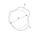
- Area size calculation unit 22 by binarizing the respective fluorescence image G 2 with a predetermined threshold value, and extracts a region (high fluorescence intensity region) R with a fluorescent intensity above a predetermined threshold, shown in Figure 2 As described above, the diameter of the circle C inscribed in the region R is calculated as the region size D of the high fluorescent luminance region R.
- the control unit 26 receives the displacement amount d calculated by the displacement amount calculation unit 21 and the region size D of the high fluorescent luminance region R calculated by the region size calculation unit 22, thereby causing a displacement amount with respect to the region size D. calculating a ratio d / D of d, the ratio d / D was the stop normalized calculation of fluorescence image G 2 by normalizing calculation unit 23 when bigger than a predetermined ratio, the ratio the ratio d / D is given It adapted to perform normalization operation of the fluorescence image G 2 by normalizing calculation unit 23 only when smaller.
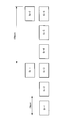
- the exposure time of the white light image G 1 ( ⁇ 1 to ⁇ 6) is 33 msec and the exposure time of the fluorescent image G 2 is 100 msec, the observation period is 100 msec.
- three white light image G 1 is the fluorescence image G 2 is acquired one.
- the normalization calculation of the fluorescence image G 2 is performed by using the fluorescence images G 2 -1, G 2 -2 and the white light images G 1 -3, G 1 -6 acquired for each observation period. Is called.
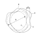
- the fluorescence image G 2 and the white-light image G 1 is and provided that overlaps substantially half of the height fluorescent intensity region R which is assumed as a lesion it can be considered between the white light image G 1 obtained in two intervals, to be acceptable be shifted to the half of the area size D of the high fluorescence intensity region R. That is, when the diameter of the circle representing the region size D is D, it can be considered that the accuracy of normalization is maintained when the displacement amount d shown in FIG. 3 is 1 ⁇ 2 D or less in about 100 msec. .
- control unit 26 the ratio of the displacement amount d with respect to the area size D of the fluorescence image G 2 is equal to or less than half, normalized by normalizing calculation unit 23 as long as 1/2 or less When the value is larger than 1 ⁇ 2, normalization by the normalization calculation unit 23 is prohibited.
- Normalizing calculation unit 23 when the control unit 26 is permitted normalization, the fluorescence image G 2 which has been input from the fluorescence image generating unit 18, the white light image which has been inputted from the white light image generating section 17 By dividing by G 1 , a normalized fluorescence image G 2 ′ is calculated. Then, the image composition unit 24 parallels (or superimposes) the white light image G 1 sent from the white light image generation unit 17 and the normalized fluorescent image G 2 ′ output from the normalization calculation unit 23. A composite image G is generated and output to the monitor 7.
- a region having a luminance value higher than a predetermined threshold value of the normalized fluorescence image G 2 ′ is colored with a color such as blue, and the white light image it is desirable to superimpose the G 1.
- step S 2 A fluorescence image processing method using the fluorescence observation apparatus 1 according to the present embodiment configured as described above will be described below.
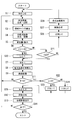
- the fluorescence image generation unit 18 when the counter N is reset (step S ⁇ b > 1) and the fluorescence image signal is acquired by the imaging element 15, the fluorescence image generation unit 18 generates the fluorescence image G ⁇ b > 2 based on the fluorescence image signal. While being generated, it is sequentially stored in the fluorescence image storage unit 20 (step S2).
- Fluorescence image G 2 stored in the fluorescence image storage unit 20 is sent to the region size calculation unit 22.
- the region size calculation unit 22 are fluorescence image G 2 are sequentially processed sent at time intervals 100msec corresponding to the observation period from the fluorescence image storage unit 20, the high fluorescence intensity region R are extracted, as its size A diameter dimension D of the inscribed circle C is calculated (step S3).
- the white light image generation unit 17 when the white light image signal is acquired by the imaging device 14, the white light image generation unit 17 generates the white light image G 1 based on the white light image signal and sequentially stores the white light image G 1 in the white light image storage unit 19. (Step S4).
- the white light image G 1 stored in the white light image storage unit 19 is sent to the displacement amount calculation unit 21.
- the displacement amount calculation unit 21 sent from the white light image storage unit 19, the two white-light image G 1 successive acquired at a time interval 100msec corresponding to the observation period, it is sequentially image processing Te are feature points of each of the white light image G 1 is extracted, the distance between the same feature point in between the two white-light image G 1 is calculated.
- the displacement amount d is calculated indicating whether the observation object A relative to the distal end surface 2a of the insertion portion 2 is relatively moved much (Ste S5).
- the displacement amount d calculated by the displacement amount calculation unit 21 and the region size D of the high fluorescent luminance region R calculated by the region size calculation unit 22 are sent to the control unit 26.
- the ratio of the displacement amount d to the sent region size D is calculated.
- the control unit 26 allows the normalization calculation by the normalization calculation unit 23 (step S6). Normalizing calculation unit 23, the normalized operation is allowed by the control unit 26 increments the counter N (step S7), and normalized by dividing the fluorescence image G 2 in the white light image G 1 ( Step S8). Then, the generated standardized fluorescent image G 2 ′ is stored in the standardized image storage unit 25 (step S9), and then the processes from step S2 are repeated.
- step S10 is greater than the ratio d / D of the displacement amount d is 1/2 for area size D without performing normalization operation, to display the white light image G 1 on the monitor 7, the process from step S1 Repeated (step S10).
- step S11 the standardized fluorescent image G 2 ′ is combined with the white light image G 1 in the image combining unit 24 (step S 12), and the generated combined image G is displayed on the monitor 7. (Step S13).
- step S14 the process from step S2 is repeated (step S14).
- step S2 if the ratio d / D of the displacement amount d with respect to the area size D even once exceeds 1/2, the display of only the white light image G 1 at that time After switching, the process returns to step S1 and the counter N is reset.
- the position of the fluorescence image G 2, a white-light image G 1 used the fluorescence image G 2 in order to standardize the deviation is determined by the displacement amount d in the white light image G 1, when the position deviation is large, does not perform normalization, without displaying the low normalized fluorescence image G 2 'accuracy, incorrect doctor or the like It is possible to prevent an inconvenience that information is provided.
- the normalized fluorescent image G 2 ′ is displayed only when the displacement amount d is small continuously for 10 times or more by the counter N, when the displacement amount d is large or when the state where the displacement amount d is small does not continue.
- the standardized fluorescent image G 2 ′ is not displayed, and it is possible to prevent the inconvenience that the synthesized image G and the white light image G 1 are switched in a short time (1 second or less).
- the synthesized image G is displayed only when the observation period is 100 msec and the displacement d is small for 10 observation periods.
- the observation period and the number of counters N can be arbitrarily set.
- the ratio d / D of the displacement amount d with respect to the area size D exceeds 1/2 was decided to stop the normalized fluorescence image G 2
- the ratio d / D is not limited to 1/2 and can be set arbitrarily. For example, if the ratio d / D is greater than 1, i.e., if the area size D and the displacement amount d is equal to, if is completely displaced without the fluorescence image G 2 and the white-light image G 1 is duplicated it is considered, in which case stop normalized fluorescence image G 2 only, may be possible to perform the normalization otherwise. In this way, it is possible to shorten the period normalized fluorescence image G 2 is stopped.
- the accuracy of normalization may be displayed together.
- the ratio d / D of the displacement amount d to the region size D is 1 ⁇ 2 or less, it is classified into three cases of greater than 1 ⁇ 2 and less than 1 and greater than 1, and 10 observation cycles
- the accuracy of normalization may be set to LEVEL1, LEVEL3 if it is larger than 1, or LEVEL2 in other cases.
- step S1 when the counter N and the counter L are initialized in step S1, and the ratio d / D of the displacement amount d to the region size D is determined to be 1/2 or less in step S6, the counters L and N Is incremented (steps S20 and S7), and when it is determined that the ratio d / D is greater than 1/2 and equal to or less than 1 (step S21), only the counter N is incremented (step S7).
- step S12 reset the counter N, L (step S25), and the image synthesizing unit 24 and the normalized fluorescence image G 2 'white light image G 1, and information indicating the accuracy of normalized are synthesized (step S12), the As shown in FIG. 7, the generated composite image G is displayed on the monitor 7 (step S13). Then, it is determined whether or not the observation is finished. If the observation is to be continued, the process from step S2 is repeated (step S14).
- step S21 when the ratio d / D is determined to be larger than 1 in step S21, the normalized precision is set to LEVEL3 (step S26), the white-light image G 1, to a standardized accuracy is LEVEL3 The information shown is combined (step S27), and the generated combined image G is displayed on the monitor 7 (step S28).
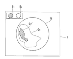
- FIG. 7 shows a state of LEVEL 2 in which only one display B 1 is lit.
- the display method of the accuracy of this normalization is not limited to the example of FIG. 7, but is arbitrary. Further, instead of displaying on the monitor 7, notification may be made by voice or the like.
- control unit 26 may change the threshold value for standardization according to the accuracy of standardization. That is, when the observation is started, the standardization accuracy level is set after the initialization of the counters N and M in step S1 (step S30). As shown in FIG. 8, the control unit 26 stores the standardization accuracy level and the threshold S in association with each other. In the initial setting, for example, the standardization accuracy is set to LEVEL1 that is the strictest threshold S. Level is set. At this time, the threshold value S is 0, for example.
- step S31 the counter N is incremented (step S31), generated and stored fluorescence image G 2 (step S2), and calculates the area size D (step S3), and generating and storing of the white-light image G 1 (step S4) and displacement
- the amount d is calculated (step S5), and it is determined whether or not the displacement amount d is equal to or smaller than the threshold value S with respect to the region size D (step S32).
- step S34 it is determined whether or not the counter M is smaller than 7 (step S36). If M ⁇ 7, that is, if standardization is performed four times or more out of ten times, the standardization accuracy is determined. Is increased by one level (step S37). If you are at the highest level, no further level up will be made.
- Step S 12 the standardized fluorescent image G 2 ′, the white light image G 1, and the information indicating the accuracy of standardization are synthesized in the image synthesis unit 24 (step S 12), and the generated synthesized image G is displayed on the monitor 7. (Step S13). Then, it is determined whether or not the observation is finished. If the observation is to be continued, the process from step S31 is repeated (step S14). By doing in this way, the normalization calculation is always performed at a constant time ratio, and the normalization calculation suitable for the observation environment can be performed.
- two or more types of patterns are stored as values in which the standardization accuracy level stored in the control unit 26 illustrated in FIG. 8 is associated with the threshold value S, and a touch switch provided on the monitor 7. For example, a pattern suitable for the observation condition may be selected. Further, by connecting the insertion section 2 of the endoscope to the image processing section 6, an ID (recognition code) built in the insertion section is sent to the control section 26, and a pattern suitable for the insertion section to be used is selected. It may come to be.
Landscapes
- Life Sciences & Earth Sciences (AREA)
- Health & Medical Sciences (AREA)
- Surgery (AREA)
- Engineering & Computer Science (AREA)
- Biophysics (AREA)
- Biomedical Technology (AREA)
- Veterinary Medicine (AREA)
- Public Health (AREA)
- Pathology (AREA)
- General Health & Medical Sciences (AREA)
- Animal Behavior & Ethology (AREA)
- Physics & Mathematics (AREA)
- Heart & Thoracic Surgery (AREA)
- Medical Informatics (AREA)
- Molecular Biology (AREA)
- Radiology & Medical Imaging (AREA)
- Optics & Photonics (AREA)
- Nuclear Medicine, Radiotherapy & Molecular Imaging (AREA)
- Signal Processing (AREA)
- Endoscopes (AREA)
Abstract
蛍光画像と反射光画像との間に位置ズレが発生した場合でも、医師に誤った情報が与えられるのを防止し誤診防止を図る。観察対象(A)に照射した白色光の反射光から白色光画像(G1)を生成する白色光画像生成部(17)と、観察対象(A)に励起光を照射し蛍光画像(G2)を生成する蛍光画像生成部(18)と、蛍光画像(G2)を白色光画像(G1)により規格化する蛍光画像補正部(23)と、時間間隔をあけた複数の白色光画像(G1)を処理し観察対象(A)の変位量(d)を算出する変位量算出部(21)と、蛍光画像(G2)を処理し所定の閾値以上の蛍光強度を有する領域の大きさ(D)を算出する領域サイズ算出部(22)と、領域の大きさ(D)に対し、観察対象(A)の変位量(d)が所定の割合以上に大きいときに、蛍光画像(G2)の規格化を停止するよう蛍光画像補正部(23)を制御する制御部(26)とを備える蛍光観察装置(1)を提供する。
Description
本発明は、蛍光観察装置および蛍光画像処理方法に関する。
従来、生体組織に存在する腫瘍等の病変部に特異的に集積する蛍光物質からの蛍光強度を同じ生体組織の表面における反射光強度によって規格化する蛍光観察装置が知られている(例えば、特許文献1参照。)。
しかしながら、生体組織の蛍光観察は、生体組織に対して励起光を照射することにより行われ、生体組織の反射光観察は、生体組織に白色光等を照射することにより行われるため、蛍光観察と反射光観察との時間的なズレによって、取得される蛍光画像と反射光画像との間にズレが発生することがある。蛍光画像と反射光画像との間のズレは、生体組織の脈動、露光時間の相違、蛍光観察装置と生体組織との相対的な位置ズレ等によって発生する。
この場合に、蛍光画像に対してズレを有する反射光画像によって蛍光画像を規格化したのでは、正しい規格化が行われないため、病変部位ではない箇所に病変が存在するかのような表示されてしまったり、病変部位が病変ではない箇所であるかのように表示されてしまったりして、医師に誤った情報を与えてしまうことになるという不都合がある。
本発明は、上述した事情に鑑みてなされたものであって、蛍光画像と反射光画像との間に位置ズレが発生した場合であっても、医師に誤った情報が与えられるのを防止して、誤診防止を図ることができる蛍光観察装置および蛍光画像処理方法を提供する。
上記目的を達成するために、本発明は以下の手段を提供する。
本発明の第一の態様は、観察対象に照射した白色光の反射光を撮影して得られた信号から白色光画像を生成する白色光画像生成部と、観察対象に励起光を照射して発生した蛍光を撮影して得られた信号から蛍光画像を生成する蛍光画像生成部と、該蛍光画像生成部により生成された蛍光画像を前記白色光画像生成部により生成された白色光画像によって規格化する蛍光画像補正部と、時間間隔を空けて撮影されることにより得られた信号から前記白色光画像生成部により生成された複数の白色光画像を処理して該白色光画像内の前記観察対象の変位量を算出する変位量算出部と、前記蛍光画像生成部により生成された蛍光画像を処理して所定の閾値以上の蛍光強度を有する領域の大きさを算出する領域サイズ算出部と、該領域サイズ算出部により算出された前記領域の大きさに対し、前記変位量算出部により算出された前記観察対象の変位量が所定の割合以上に大きいときに、蛍光画像の規格化を停止するよう前記蛍光画像補正部を制御する制御部とを備える蛍光観察装置である。
本発明の第一の態様は、観察対象に照射した白色光の反射光を撮影して得られた信号から白色光画像を生成する白色光画像生成部と、観察対象に励起光を照射して発生した蛍光を撮影して得られた信号から蛍光画像を生成する蛍光画像生成部と、該蛍光画像生成部により生成された蛍光画像を前記白色光画像生成部により生成された白色光画像によって規格化する蛍光画像補正部と、時間間隔を空けて撮影されることにより得られた信号から前記白色光画像生成部により生成された複数の白色光画像を処理して該白色光画像内の前記観察対象の変位量を算出する変位量算出部と、前記蛍光画像生成部により生成された蛍光画像を処理して所定の閾値以上の蛍光強度を有する領域の大きさを算出する領域サイズ算出部と、該領域サイズ算出部により算出された前記領域の大きさに対し、前記変位量算出部により算出された前記観察対象の変位量が所定の割合以上に大きいときに、蛍光画像の規格化を停止するよう前記蛍光画像補正部を制御する制御部とを備える蛍光観察装置である。
上記本発明の第一の態様に係る蛍光観察装置によれば、白色光画像生成部により生成された観察対象の時間間隔を空けた複数の白色光画像が得られると、変位量算出部によって、白色光画像内における観察対象の変位量が算出される。一方、蛍光画像生成部により生成された観察対象の蛍光画像が得られると、領域サイズ算出部により、蛍光画像内の所定の閾値以上の蛍光強度を有する領域の大きさが算出される。
そして、高蛍光強度領域の大きさに対して、観察対象の変位量が大きくなっていくと、蛍光画像を白色光画像で規格化する際の精度が低下していくので、所定の割合以上に大きく変位しているときには、制御部が蛍光画像補正部による蛍光画像の規格化を停止することにより、低い精度で規格化された蛍光画像が生成されるのを防止することができる。すなわち、制御部は、高蛍光強度領域の大きさに対して、観察対象の変位量が所定の割合より小さいときにのみ蛍光画像の規格化を行うこととして、高い精度で規格化された蛍光画像のみを生成して、医師に誤った情報が与えられるのを未然に防止することができる。
上記本発明の第一の態様に係る蛍光観察装置において、前記制御部が前記蛍光画像補正部による蛍光画像の規格化を停止しているときに、その旨を報知する規格化停止報知部を備えていてもよい。
このようにすることで、規格化停止報知部により、制御部が蛍光画像の規格化を停止していることを医師等が認識することができる。
このようにすることで、規格化停止報知部により、制御部が蛍光画像の規格化を停止していることを医師等が認識することができる。
上記本発明の第一の態様に係る蛍光観察装置において、前記領域サイズ算出部により算出された前記領域の大きさと、前記変位量算出部により算出された前記観察対象の変位量とに基づいて、前記蛍光画像補正部による規格化の精度を算出する規格化精度算出部と、該規格化精度算出部により算出された規格化の精度を報知する規格化精度報知部とを備えていてもよい。
このようにすることで、高蛍光輝度領域の大きさに対して観察対象の変位量が大きくなっていくほど、蛍光画像と白色光画像との位置ズレが大きくなって規格化の精度が低下していくため、規格化精度算出部により算出した精度を規格化精度報知部によって報知することで、規格化された蛍光画像の信頼性を医師等が認識することができる。
このようにすることで、高蛍光輝度領域の大きさに対して観察対象の変位量が大きくなっていくほど、蛍光画像と白色光画像との位置ズレが大きくなって規格化の精度が低下していくため、規格化精度算出部により算出した精度を規格化精度報知部によって報知することで、規格化された蛍光画像の信頼性を医師等が認識することができる。
上記本発明の第一の態様に係る蛍光観察装置において、前記制御部によって前記蛍光画像補正部による蛍光画像の規格化が停止されている時間の比率を算出する停止比率算出部と、前記制御部が、前記停止比率算出部により算出された規格化の停止時間の比率に基づいて、前記割合を調節してもよい。
このようにすることで、蛍光画像と白色光画像との位置ズレが大きいときには、規格化が停止されたままの状態となってしまうので、規格化を停止するための割合を緩和して、精度が低いながらも規格化された蛍光画像が得られるようにすることができる。
このようにすることで、蛍光画像と白色光画像との位置ズレが大きいときには、規格化が停止されたままの状態となってしまうので、規格化を停止するための割合を緩和して、精度が低いながらも規格化された蛍光画像が得られるようにすることができる。
本発明の第二の態様は、観察対象に照射した白色光の反射光を撮影して得られた信号から白色光画像を生成する白色光画像生成ステップと、観察対象に励起光を照射して発生した蛍光を撮影して得られた信号から蛍光画像を生成する蛍光画像生成ステップと、該蛍光画像生成ステップにより生成された蛍光画像を処理して所定の閾値以上の蛍光強度を有する領域の大きさを算出する領域サイズ算出ステップと、時間間隔を空けて撮影されることにより得られた信号から生成された複数の白色光画像を処理して該白色光画像内の前記観察対象の変位量を算出する変位量算出ステップと、前記領域サイズ算出ステップにより算出された前記領域の大きさに対し、前記変位量算出ステップにより算出された前記観察対象の変位量が所定の割合より小さいときにのみ、前記蛍光画像を前記白色光画像により規格化する蛍光画像補正ステップとを含む蛍光画像処理方法である。
本発明によれば、蛍光画像と反射光画像との間に位置ズレが発生した場合であっても、医師に誤った情報が与えられるのを防止して、誤診防止を図ることができるという効果を奏する。
本発明の一実施形態に係る蛍光観察装置1および蛍光画像処理方法について、図面を参照して以下に説明する。
本実施形態に係る蛍光観察装置1は、蛍光内視鏡装置であって、体内に挿入される細長い挿入部2と、白色光および励起光を射出する光源装置3と、該光源装置3からの白色光および励起光を挿入部2の先端から観察対象Aに向けて照射する照明ユニット4と、挿入部2の先端に設けられ、観察対象Aである生体組織の画像情報を取得する撮像ユニット5と、挿入部2の基端側に配置され、撮像ユニット5により取得された画像情報を処理する画像処理部6と、該画像処理部6により処理された画像Gを表示するモニタ7とを備えている。
本実施形態に係る蛍光観察装置1は、蛍光内視鏡装置であって、体内に挿入される細長い挿入部2と、白色光および励起光を射出する光源装置3と、該光源装置3からの白色光および励起光を挿入部2の先端から観察対象Aに向けて照射する照明ユニット4と、挿入部2の先端に設けられ、観察対象Aである生体組織の画像情報を取得する撮像ユニット5と、挿入部2の基端側に配置され、撮像ユニット5により取得された画像情報を処理する画像処理部6と、該画像処理部6により処理された画像Gを表示するモニタ7とを備えている。
照明ユニット4は、挿入部2の長手方向のほぼ全長にわたって配置され、光源装置3から射出された白色光および励起光を導光するライトガイドファイバ8と、挿入部2の先端に設けられ、ライトガイドファイバ8によって導光されてきた白色光および励起光を拡散させて、挿入部2の先端面2aに対向する観察対象Aに照射する照明光学系9とを備えている。
撮像ユニット5は、観察対象Aの所定の観察範囲から戻る戻り光を集光する対物レンズ10と、該対物レンズ10によって集光された戻り光の内、励起波長以上の光(励起光および蛍光)を反射し、励起波長より短い波長の白色光を透過するダイクロイックミラー12と、ダイクロイックミラー12を透過した白色光およびダイクロイックミラー12により反射された蛍光をそれぞれ集光する2つの集光レンズ11,13と、集光レンズ11,13によって集光された白色光および蛍光を撮像するCCDのような2個の撮像素子14,15とを備えている。図中、符号16は、ダイクロイックミラー12によって反射された光から励起光を遮断する励起光カットフィルタである。
画像処理部6は、図1に示されるように、撮像素子14により時間間隔を空けて取得されてくる白色光画像信号から白色光画像G1を順次生成する白色光画像生成部17と、撮像素子15により時間間隔を空けて取得されてくる蛍光画像信号から蛍光画像G2を順次生成する蛍光画像生成部18と、白色光画像生成部17により順次生成された白色光画像G1を順次記憶する白色光画像記憶部19と、蛍光画像生成部18により順次生成された蛍光画像G2を順次記憶する蛍光画像記憶部20とを備えている。
また、画像処理部6は、白色光画像記憶部19に記憶されている白色光画像G1から挿入部2先端面2aに対する観察対象Aの相対的な変位量を算出する変位量算出部21と、蛍光画像記憶部20に記憶されている蛍光画像G2から病変部位に相当すると予想される領域を抽出しその大きさ(領域サイズ)を算出する領域サイズ算出部22とを備えている。
さらに、画像処理部6は、白色光画像生成部17により生成された白色光画像G1と蛍光画像生成部18により生成された蛍光画像G2とを用いて、蛍光画像G2を規格化する規格化演算部23と、規格化された蛍光画像(以下、規格化蛍光画像とも言う。)G2’を白色光画像G1と合成する画像合成部24と、規格化蛍光画像を記憶する規格化画像記憶部25とを備えている。
さらに、画像処理部6は、変位量算出部21により算出された変位量dと領域サイズ算出部22により算出された領域サイズDとに基づいて、規格化演算部23による蛍光画像G2の規格化の是非を判定して、規格化演算部23を制御する制御部26を備えている。
変位量算出部21は、例えば、観察周期に対応する時間間隔を空けて撮影された2枚の連続する白色光画像G1のそれぞれにおいて、共通する特徴点(例えば、高輝度領域等)を抽出し、抽出された特徴点間の距離を求めることにより、2枚の白色光画像G1が取得された間における挿入部2の先端面2aと観察対象Aとの相対的な変位量dを算出するようになっている。
領域サイズ算出部22は、各蛍光画像G2を所定の閾値で二値化処理することにより、所定の閾値以上の蛍光輝度を有する領域(高蛍光輝度領域)Rを抽出し、図2に示されるように、その領域Rに内接する円Cの直径をその高蛍光輝度領域Rの領域サイズDとして算出するようになっている。
領域サイズ算出部22は、各蛍光画像G2を所定の閾値で二値化処理することにより、所定の閾値以上の蛍光輝度を有する領域(高蛍光輝度領域)Rを抽出し、図2に示されるように、その領域Rに内接する円Cの直径をその高蛍光輝度領域Rの領域サイズDとして算出するようになっている。
制御部26は、変位量算出部21において算出された変位量dと領域サイズ算出部22により算出された高蛍光輝度領域Rの領域サイズDとが入力されることにより、領域サイズDに対する変位量dの割合d/Dを算出し、その割合d/Dが所定の割合以上に大きいときには規格化演算部23による蛍光画像G2の規格化演算を停止させ、その割合d/Dが所定の割合より小さいときにのみ規格化演算部23による蛍光画像G2の規格化演算を行わせるようになっている。
例えば、図4に示されるように、白色光画像G1(-1~-6)の露光時間が33msecであり、蛍光画像G2の露光時間が100msecである場合に、観察周期100msecの間に白色光画像G1は3枚、蛍光画像G2は1枚取得される。本実施形態においては、蛍光画像G2の規格化演算は、観察周期毎に取得された蛍光画像G2-1,G2-2と白色光画像G1-3,G1-6とによって行われる。
ここで、規格化の精度を十分に担保するために、蛍光画像G2と白色光画像G1とが、病変部位として想定される高蛍光輝度領域Rの略半分重なっていることを条件とすると、2枚おきに取得された白色光画像G1間で、高蛍光輝度領域Rの領域サイズDの1/2までずれていても許容されると考えることができる。すなわち、領域サイズDを表す円の直径をDとすると、図3に示される変位量dが約100msecの間に1/2D以下である場合に規格化の精度が維持されると考えることができる。
そこで、制御部26は、蛍光画像G2の領域サイズDに対する変位量dの割合が1/2以下であるか否かを判定し、1/2以下であれば規格化演算部23による規格化を許容し、1/2より大きい場合には規格化演算部23による規格化を禁止するようになっている。
規格化演算部23は、制御部26から規格化を許容された場合に、蛍光画像生成部18から入力されてきた蛍光画像G2を、白色光画像生成部17から入力されてきた白色光画像G1によって除算することにより、規格化蛍光画像G2’を算出するようになっている。そして、画像合成部24は、白色光画像生成部17から送られてきた白色光画像G1と、規格化演算部23から出力された規格化蛍光画像G2’とを並列(あるいは重畳)した合成画像Gを生成し、モニタ7に出力するようになっている。規格化蛍光画像G2’を白色光画像G1に重畳する場合には、規格化蛍光画像G2’の所定の閾値より高い輝度値を有する領域に青色等の色を付して白色光画像G1に重畳することが望ましい。
このように構成された本実施形態に係る蛍光観察装置1を用いた蛍光画像処理方法について、以下に説明する。
まず、図5に示されるように、カウンタNがリセットされ(ステップS1)、撮像素子15によって蛍光画像信号が取得されると、蛍光画像生成部18によって蛍光画像信号に基づいて蛍光画像G2が生成されるとともに、蛍光画像記憶部20に順次記憶されていく(ステップS2)。
まず、図5に示されるように、カウンタNがリセットされ(ステップS1)、撮像素子15によって蛍光画像信号が取得されると、蛍光画像生成部18によって蛍光画像信号に基づいて蛍光画像G2が生成されるとともに、蛍光画像記憶部20に順次記憶されていく(ステップS2)。
蛍光画像記憶部20に記憶された蛍光画像G2は、領域サイズ算出部22に送られる。領域サイズ算出部22においては、蛍光画像記憶部20から観察周期に対応する時間間隔100msecで送られてきた蛍光画像G2が順次処理されて、高蛍光輝度領域Rが抽出され、その大きさとして内接円Cの直径寸法Dが算出される(ステップS3)。
一方、撮像素子14によって白色光画像信号が取得されると、白色光画像生成部17によって白色光画像信号に基づいて白色光画像G1が生成されるとともに、白色光画像記憶部19に順次記憶される(ステップS4)。
白色光画像記憶部19に記憶された白色光画像G1は、変位量算出部21に送られる。変位量算出部21においては、白色光画像記憶部19から送られてきた、観察周期に対応する時間間隔100msecをあけて取得された連続する2枚の白色光画像G1が、順次画像処理されて、それぞれの白色光画像G1内の特徴点が抽出され、2つの白色光画像G1間において同一の特徴点間の距離が算出される。
白色光画像記憶部19に記憶された白色光画像G1は、変位量算出部21に送られる。変位量算出部21においては、白色光画像記憶部19から送られてきた、観察周期に対応する時間間隔100msecをあけて取得された連続する2枚の白色光画像G1が、順次画像処理されて、それぞれの白色光画像G1内の特徴点が抽出され、2つの白色光画像G1間において同一の特徴点間の距離が算出される。
これにより、2枚の白色光画像G1が取得される間に、挿入部2の先端面2aに対して観察対象Aがどれだけ相対的に移動したかを示す変位量dが算出される(ステップS5)。
変位量算出部21において算出された変位量dと領域サイズ算出部22において算出された高蛍光輝度領域Rの領域サイズDは制御部26に送られる。
変位量算出部21において算出された変位量dと領域サイズ算出部22において算出された高蛍光輝度領域Rの領域サイズDは制御部26に送られる。
制御部26においては、送られてきた領域サイズDに対する変位量dの割合が算出される。制御部26は、領域サイズDに対する変位量dの割合d/Dが1/2以下である場合には、規格化演算部23による規格化演算を許容する(ステップS6)。規格化演算部23は、制御部26によって規格化演算が許容されると、カウンタNをインクリメントして(ステップS7)、蛍光画像G2を白色光画像G1で除算することにより規格化する(ステップS8)。そして、生成された規格化蛍光画像G2’は規格化画像記憶部25に記憶され(ステップS9)、その後、ステップS2からの工程が繰り返される。
一方、領域サイズDに対する変位量dの割合d/Dが1/2より大きい場合には、規格化演算を行わずに、白色光画像G1をモニタ7に表示させ、ステップS1からの工程が繰り返される(ステップS10)。
ステップS2からの工程の繰り返し中に、領域サイズDに対する変位量dの割合d/Dが1/2を超えない限り、カウンタNの値はインクリメントされ続け、カウンタN=10となったか否か、すなわち、10回連続して変位量が小さかったか否かが判定される(ステップS11)。カウンタN=10となった場合には、画像合成部24において規格化蛍光画像G2’が白色光画像G1と合成され(ステップS12)、生成された合成画像Gがモニタ7に表示される(ステップS13)。以後、カウンタN≧10である限り、すなわち、変位量dが少ない状態が10回以上連続している限り、規格化蛍光画像G2’が白色光画像G1と合成され、生成された合成画像Gがモニタ7に表示される。そして、観察の終了か否かが判断され、継続する場合は、ステップS2からの工程が繰り返される(ステップS14)。
一方、ステップS2からの工程の繰り返し中に、1度でも領域サイズDに対する変位量dの割合d/Dが1/2を超えた場合には、その時点で白色光画像G1のみの表示に切り替えられ、ステップS1に戻ってカウンタNがリセットされる。
このように、本実施形態に係る蛍光観察装置1および蛍光画像処理方法によれば、蛍光画像G2と、該蛍光画像G2を規格化するために使用される白色光画像G1との位置ズレを白色光画像G1における変位量dによって判定し、位置ズレが大きい場合には、規格化を行わないので、精度の低い規格化蛍光画像G2’が表示されず、医師等に誤った情報が提供されてしまう不都合の発生を未然に防止することができる。
また、カウンタNにより10回以上連続して変位量dが小さい場合にのみ規格化蛍光画像G2’を表示するので、変位量dが大きい場合や、変位量dが小さい状態が継続しない場合には、規格化蛍光画像G2’の表示が行われず、合成画像Gと白色光画像G1とが短い時間(1秒以下)で切り替わってしまう不都合の発生を防止できる。
なお、本実施形態においては、観察周期を100msecとし、10回分の観察周期にわたって変位量dが小さい状態が継続していた場合にのみ、合成画像Gを表示することとしたが、これに限定されるものではなく、観察周期やカウンタNの回数は任意に設定することができる。
なお、本実施形態においては、観察周期を100msecとし、10回分の観察周期にわたって変位量dが小さい状態が継続していた場合にのみ、合成画像Gを表示することとしたが、これに限定されるものではなく、観察周期やカウンタNの回数は任意に設定することができる。
また、本実施形態に係る蛍光画像処理方法においては、領域サイズDに対する変位量dの割合d/Dが1/2を超えた場合には蛍光画像G2の規格化を停止することとしたが、その割合d/Dは1/2に限定されるものではなく、任意に設定することができる。例えば、割合d/Dが1を超える場合、すなわち、領域サイズDと変位量dとが等しい場合には、蛍光画像G2と白色光画像G1とが重複することなく完全にずれていると考えられるため、その場合にのみ蛍光画像G2の規格化を停止し、それ以外の場合には規格化を行わせることにしてもよい。このようにすることで、蛍光画像G2の規格化が停止される期間を短縮することができる。
また、この場合に、図6および図7に示されるように、規格化の精度を示す情報を併せて表示することにしてもよい。
例えば、領域サイズDに対する変位量dの割合d/Dが1/2以下である場合、1/2より大きく1以下である場合および1より大きい場合の3つに分類し、10回の観察周期で算出された割合d/Dが全て1/2以下である場合に規格化の精度をLEVEL1、1回でも1より大きい場合にはLEVEL3、それ以外の場合をLEVEL2に設定することにしてもよい。
例えば、領域サイズDに対する変位量dの割合d/Dが1/2以下である場合、1/2より大きく1以下である場合および1より大きい場合の3つに分類し、10回の観察周期で算出された割合d/Dが全て1/2以下である場合に規格化の精度をLEVEL1、1回でも1より大きい場合にはLEVEL3、それ以外の場合をLEVEL2に設定することにしてもよい。
具体的には、ステップS1においてカウンタNおよびカウンタLを初期化し、ステップS6において領域サイズDに対する変位量dの割合d/Dが1/2以下であると判断された場合に、カウンタL,Nをインクリメントし(ステップS20,S7)、割合d/Dが1/2より大きく1以下であると判断された場合に(ステップS21)、カウンタNのみをインクリメントする(ステップS7)。
そして、これらの場合には、いずれも蛍光画像G2の規格化が実施され(ステップS8)、規格化蛍光画像G2’が記憶される(ステップS9)。そして、ステップS11において、カウンタN=10となった場合には、カウンタL=0であるか否かが判定され(ステップS22)、カウンタL=0の場合、すなわち、割合d/Dが10回分の観察周期にわたって常に1/2以下であった場合には、規格化の精度をLEVEL1とし(ステップS23)、それ以外の場合、すなわち、1回でも1/2より大きくD以下の場合があった場合には、規格化の精度をLEVEL2とする(ステップS24)。
その後、カウンタN,Lをリセットし(ステップS25)、画像合成部24において規格化蛍光画像G2’と白色光画像G1と、規格化の精度を示す情報とが合成され(ステップS12)、図7に示されるように、生成された合成画像Gがモニタ7に表示される(ステップS13)。そして、観察の終了か否かが判断され、継続する場合は、ステップS2からの工程が繰り返される(ステップS14)。
一方、ステップS21において割合d/Dが1より大きいと判断されたときには、規格化の精度がLEVEL3に設定され(ステップS26)、白色光画像G1と、規格化の精度がLEVEL3であることを示す情報とが合成され(ステップS27)、生成された合成画像Gがモニタ7に表示される(ステップS28)。
図7に示す例では、規格化の精度が最も高いLEVEL1の場合に2つの円形の表示B1,B2が両方とも点灯し、LEVEL2の場合には1つの表示B1のみが点灯し、LEVEL3の場合には1つも点灯しないようにしている。図7は1つの表示B1のみが点灯しているLEVEL2の状態を示している。この規格化の精度の表示方法は、図7の例に限定されるものではなく任意である。また、モニタ7に表示することに代えて、音声等によって報知することにしてもよい。
また、図8および図9に示されるように、制御部26が規格化の精度に応じて規格化を行うための閾値を変更することにしてもよい。すなわち、観察が開始されると、ステップS1におけるカウンタN,Mの初期化後に、規格化精度のレベルを設定する(ステップS30)。制御部26は、図8に示されるように、規格化精度のレベルと閾値Sとを対応づけて記憶しており、最初の設定においては、例えば、最も厳しい閾値SとなるLEVEL1に規格化精度のレベルが設定される。このとき閾値Sは例えば0である。
次いで、カウンタNがインクリメントされ(ステップS31)、蛍光画像G2の生成・記憶(ステップS2)、領域サイズDの算出(ステップS3)、白色光画像G1の生成・記憶(ステップS4)および変位量dの算出が行われ(ステップS5)、変位量dが領域サイズDに対して閾値S以下であるか否かが判定される(ステップS32)。
領域サイズDに対する変位量dの割合d/Dが閾値S以下である場合には、蛍光画像G2が規格化され(ステップS8)、規格化蛍光画像G2’が記憶され(ステップS9)、カウンタN=10となるまでステップS31~S9が繰り返される。
領域サイズDに対する変位量dの割合d/Dが閾値S以下である場合には、蛍光画像G2が規格化され(ステップS8)、規格化蛍光画像G2’が記憶され(ステップS9)、カウンタN=10となるまでステップS31~S9が繰り返される。
一方、領域サイズDに対する変位量dの割合d/Dが閾値Sより大きい場合には、蛍光画像G2の規格化は行われず、カウンタMがインクリメントされて(ステップS33)、白色光画像G1が表示された後(ステップS10)、カウンタN=10となるまでステップS1~S9が繰り返される。
そして、ステップS9の終了後に、カウンタN=10となったか否かが判定され(ステップS11)、カウンタN=10となった場合には、カウンタMが9より大きいか否かが判定され(ステップS34),M>9である場合、すなわち、10回の内1度も規格化が行われなかった場合には、規格化精度のレベルを1段低くする(ステップS35)。この例では、最初LEVEL6であったレベルをLEVEL5に変更する。
一方、ステップS34においてカウンタMが7より小さいか否かが判定され(ステップS36)、M<7である場合、すなわち、10回中4回以上規格化が行われた場合には、規格化精度のレベルを1段高くする(ステップS37)。最高レベルにいる場合には、それ以上のレベルアップはなされない。
そして、画像合成部24において規格化蛍光画像G2’と白色光画像G1と、規格化の精度を示す情報とが合成され(ステップS12)、生成された合成画像Gがモニタ7に表示される(ステップS13)。そして、観察の終了か否かが判断され、継続する場合は、ステップS31からの工程が繰り返される(ステップS14)。
このようにすることで、常に一定の時間割合で規格化演算が行われ、観察環境に適した規格化演算を行うことができる。
このようにすることで、常に一定の時間割合で規格化演算が行われ、観察環境に適した規格化演算を行うことができる。
なお、図8に示した制御部26に記憶された規格化精度のレベルと閾値Sとを対応づけた値は、2種類以上のパターンが記憶されており、モニタ7上に設けられたタッチスイッチ等により、観察条件に適したパターンが選択できるようになっていてもよい。また、内視鏡の挿入部2を画像処理部6に接続することにより、挿入部に内蔵されたID(認識符号)が制御部26に送られ、使用する挿入部に適したパターンが選択されるようになっていてもよい。
1 蛍光観察装置
7 モニタ(規格化停止報知部、規格化精度報知部)
17 白色光画像生成部
18 蛍光画像生成部
21 変位量算出部
22 領域サイズ算出部
23 規格化演算部(蛍光画像補正部)
26 制御部(規格化精度算出部、停止比率算出部)
A 観察対象
d 変位量
D 領域サイズ(大きさ)
G1 白色光画像
G2 蛍光画像
R 高蛍光輝度領域(領域)
S2 蛍光画像生成ステップ
S3 領域サイズ算出ステップ
S4 白色光画像生成ステップ
S5 変位量算出ステップ
S9 規格化ステップ(蛍光画像補正ステップ)
7 モニタ(規格化停止報知部、規格化精度報知部)
17 白色光画像生成部
18 蛍光画像生成部
21 変位量算出部
22 領域サイズ算出部
23 規格化演算部(蛍光画像補正部)
26 制御部(規格化精度算出部、停止比率算出部)
A 観察対象
d 変位量
D 領域サイズ(大きさ)
G1 白色光画像
G2 蛍光画像
R 高蛍光輝度領域(領域)
S2 蛍光画像生成ステップ
S3 領域サイズ算出ステップ
S4 白色光画像生成ステップ
S5 変位量算出ステップ
S9 規格化ステップ(蛍光画像補正ステップ)
Claims (5)
- 観察対象に照射した白色光の反射光を撮影して得られた信号から白色光画像を生成する白色光画像生成部と、
観察対象に励起光を照射して発生した蛍光を撮影して得られた信号から蛍光画像を生成する蛍光画像生成部と、
該蛍光画像生成部により生成された蛍光画像を前記白色光画像生成部により生成された白色光画像によって規格化する蛍光画像補正部と、
時間間隔を空けて撮影されることにより得られた信号から前記白色光画像生成部により生成された複数の白色光画像を処理して該白色光画像内の前記観察対象の変位量を算出する変位量算出部と、
前記蛍光画像生成部により生成された蛍光画像を処理して所定の閾値以上の蛍光強度を有する領域の大きさを算出する領域サイズ算出部と、
該領域サイズ算出部により算出された前記領域の大きさに対し、前記変位量算出部により算出された前記観察対象の変位量が所定の割合以上に大きいときに、蛍光画像の規格化を停止するよう前記蛍光画像補正部を制御する制御部とを備える蛍光観察装置。 - 前記制御部が前記蛍光画像補正部による蛍光画像の規格化を停止しているときに、その旨を報知する規格化停止報知部を備える請求項1に記載の蛍光観察装置。
- 前記領域サイズ算出部により算出された前記領域の大きさと、前記変位量算出部により算出された前記観察対象の変位量とに基づいて、前記蛍光画像補正部による規格化の精度を算出する規格化精度算出部と、
該規格化精度算出部により算出された規格化の精度を報知する規格化精度報知部とを備える請求項1に記載の蛍光観察装置。 - 前記制御部によって記蛍光画像補正部による蛍光画像の規格化が停止されている時間の比率を算出する停止比率算出部と、
前記制御部が、前記停止比率算出部により算出された規格化の停止時間の比率に基づいて、前記割合を調節する請求項1に記載の蛍光観察装置。 - 観察対象に照射した白色光の反射光を撮影して得られた信号から白色光画像を生成する白色光画像生成ステップと、
観察対象に励起光を照射して発生した蛍光を撮影して得られた信号から蛍光画像を生成する蛍光画像生成ステップと、
該蛍光画像生成ステップにより生成された蛍光画像を処理して所定の閾値以上の蛍光強度を有する領域の大きさを算出する領域サイズ算出ステップと、
時間間隔を空けて撮影されることにより得られた信号から生成された複数の白色光画像を処理して該白色光画像内の前記観察対象の変位量を算出する変位量算出ステップと、
前記領域サイズ算出ステップにより算出された前記領域の大きさに対し、前記変位量算出ステップにより算出された前記観察対象の変位量が所定の割合より小さいときにのみ、前記蛍光画像を前記白色光画像により規格化する蛍光画像補正ステップとを含む蛍光画像処理方法。
Priority Applications (2)
| Application Number | Priority Date | Filing Date | Title |
|---|---|---|---|
| CN201180018227.3A CN102843952B (zh) | 2010-04-12 | 2011-04-07 | 荧光观察装置和荧光图像处理方法 |
| US13/646,169 US8421034B2 (en) | 2010-04-12 | 2012-10-05 | Fluoroscopy apparatus and fluorescence image processing method |
Applications Claiming Priority (2)
| Application Number | Priority Date | Filing Date | Title |
|---|---|---|---|
| JP2010-091431 | 2010-04-12 | ||
| JP2010091431A JP5484997B2 (ja) | 2010-04-12 | 2010-04-12 | 蛍光観察装置および蛍光観察装置の作動方法 |
Related Child Applications (1)
| Application Number | Title | Priority Date | Filing Date |
|---|---|---|---|
| US13/646,169 Continuation US8421034B2 (en) | 2010-04-12 | 2012-10-05 | Fluoroscopy apparatus and fluorescence image processing method |
Publications (1)
| Publication Number | Publication Date |
|---|---|
| WO2011129255A1 true WO2011129255A1 (ja) | 2011-10-20 |
Family
ID=44798631
Family Applications (1)
| Application Number | Title | Priority Date | Filing Date |
|---|---|---|---|
| PCT/JP2011/058780 Ceased WO2011129255A1 (ja) | 2010-04-12 | 2011-04-07 | 蛍光観察装置および蛍光画像処理方法 |
Country Status (4)
| Country | Link |
|---|---|
| US (1) | US8421034B2 (ja) |
| JP (1) | JP5484997B2 (ja) |
| CN (1) | CN102843952B (ja) |
| WO (1) | WO2011129255A1 (ja) |
Cited By (3)
| Publication number | Priority date | Publication date | Assignee | Title |
|---|---|---|---|---|
| JPWO2016175084A1 (ja) * | 2015-04-30 | 2018-02-15 | 富士フイルム株式会社 | 画像処理装置、方法及びプログラム |
| JP2020010756A (ja) * | 2018-07-13 | 2020-01-23 | ソニー・オリンパスメディカルソリューションズ株式会社 | 医療用画像処理装置及び医療用観察システム |
| JP2020074926A (ja) * | 2018-11-07 | 2020-05-21 | ソニー株式会社 | 医療用観察システム、信号処理装置及び医療用観察方法 |
Families Citing this family (8)
| Publication number | Priority date | Publication date | Assignee | Title |
|---|---|---|---|---|
| AU2002303819B2 (en) | 2001-05-17 | 2007-03-01 | Xenogen Corporation | Method and apparatus for determining target depth, brightness and size within a body region |
| JP5558178B2 (ja) * | 2010-04-07 | 2014-07-23 | オリンパス株式会社 | 蛍光観察装置 |
| JP6015452B2 (ja) * | 2013-01-07 | 2016-10-26 | 株式会社リコー | 画像処理装置、方法およびプログラム |
| CN107567412B (zh) | 2015-04-10 | 2020-11-24 | 罗伯特·博世有限公司 | 利用汽车相机使用车辆运动数据的对象位置测量 |
| WO2016203572A1 (ja) * | 2015-06-17 | 2016-12-22 | オリンパス株式会社 | 撮像装置 |
| JP7281308B2 (ja) * | 2019-03-07 | 2023-05-25 | ソニー・オリンパスメディカルソリューションズ株式会社 | 医療用画像処理装置及び医療用観察システム |
| US12239409B2 (en) | 2022-02-28 | 2025-03-04 | Visionsense Ltd. | Fluorescence imaging camera assembly for open surgery |
| CN119477805B (zh) * | 2024-10-15 | 2025-05-02 | 华东数字医学工程研究院 | 一种内窥镜图像处理方法及系统 |
Citations (4)
| Publication number | Priority date | Publication date | Assignee | Title |
|---|---|---|---|---|
| JPH07246184A (ja) * | 1994-03-09 | 1995-09-26 | Fuji Photo Optical Co Ltd | 面順次式撮像装置 |
| JPH08224209A (ja) * | 1995-02-23 | 1996-09-03 | Olympus Optical Co Ltd | 蛍光観察装置 |
| JP2006061683A (ja) * | 2004-07-30 | 2006-03-09 | Olympus Corp | 内視鏡装置 |
| JP2008173290A (ja) * | 2007-01-18 | 2008-07-31 | Olympus Corp | 蛍光観察装置および蛍光観察方法 |
Family Cites Families (3)
| Publication number | Priority date | Publication date | Assignee | Title |
|---|---|---|---|---|
| JPS62247232A (ja) * | 1986-04-21 | 1987-10-28 | Agency Of Ind Science & Technol | 蛍光測定装置 |
| KR100927286B1 (ko) * | 2005-06-08 | 2009-11-18 | 올림푸스 메디칼 시스템즈 가부시키가이샤 | 내시경 장치 및 화상 처리 장치 |
| JP2008229024A (ja) * | 2007-03-20 | 2008-10-02 | Olympus Corp | 蛍光観察装置 |
-
2010
- 2010-04-12 JP JP2010091431A patent/JP5484997B2/ja not_active Expired - Fee Related
-
2011
- 2011-04-07 WO PCT/JP2011/058780 patent/WO2011129255A1/ja not_active Ceased
- 2011-04-07 CN CN201180018227.3A patent/CN102843952B/zh not_active Expired - Fee Related
-
2012
- 2012-10-05 US US13/646,169 patent/US8421034B2/en active Active
Patent Citations (4)
| Publication number | Priority date | Publication date | Assignee | Title |
|---|---|---|---|---|
| JPH07246184A (ja) * | 1994-03-09 | 1995-09-26 | Fuji Photo Optical Co Ltd | 面順次式撮像装置 |
| JPH08224209A (ja) * | 1995-02-23 | 1996-09-03 | Olympus Optical Co Ltd | 蛍光観察装置 |
| JP2006061683A (ja) * | 2004-07-30 | 2006-03-09 | Olympus Corp | 内視鏡装置 |
| JP2008173290A (ja) * | 2007-01-18 | 2008-07-31 | Olympus Corp | 蛍光観察装置および蛍光観察方法 |
Cited By (5)
| Publication number | Priority date | Publication date | Assignee | Title |
|---|---|---|---|---|
| JPWO2016175084A1 (ja) * | 2015-04-30 | 2018-02-15 | 富士フイルム株式会社 | 画像処理装置、方法及びプログラム |
| JP2020010756A (ja) * | 2018-07-13 | 2020-01-23 | ソニー・オリンパスメディカルソリューションズ株式会社 | 医療用画像処理装置及び医療用観察システム |
| JP7134759B2 (ja) | 2018-07-13 | 2022-09-12 | ソニー・オリンパスメディカルソリューションズ株式会社 | 医療用画像処理装置及び医療用観察システム |
| JP2020074926A (ja) * | 2018-11-07 | 2020-05-21 | ソニー株式会社 | 医療用観察システム、信号処理装置及び医療用観察方法 |
| JP7286948B2 (ja) | 2018-11-07 | 2023-06-06 | ソニーグループ株式会社 | 医療用観察システム、信号処理装置及び医療用観察方法 |
Also Published As
| Publication number | Publication date |
|---|---|
| JP2011218003A (ja) | 2011-11-04 |
| CN102843952A (zh) | 2012-12-26 |
| US8421034B2 (en) | 2013-04-16 |
| CN102843952B (zh) | 2015-03-25 |
| JP5484997B2 (ja) | 2014-05-07 |
| US20130026390A1 (en) | 2013-01-31 |
Similar Documents
| Publication | Publication Date | Title |
|---|---|---|
| JP5484997B2 (ja) | 蛍光観察装置および蛍光観察装置の作動方法 | |
| JP6581984B2 (ja) | 内視鏡システム | |
| JP5993237B2 (ja) | 蛍光観察装置 | |
| JP6017219B2 (ja) | 蛍光観察装置および蛍光観察システム | |
| US8547425B2 (en) | Fluorescence observation apparatus and fluorescence observation method | |
| US8965474B2 (en) | Tissue imaging system and in vivo monitoring method | |
| CN102197984B (zh) | 电子内视镜系统及其处理器单元、和获得血管信息的方法 | |
| JP5294723B2 (ja) | 画像取得装置 | |
| JP5634755B2 (ja) | 電子内視鏡システム、電子内視鏡用のプロセッサ装置、及び電子内視鏡システムの作動方法 | |
| US9241615B2 (en) | Image acquisition and display method and image capturing and display apparatus | |
| WO2013035531A1 (ja) | 内視鏡システム及び画像表示方法 | |
| EP2412289A1 (en) | Fluorescence observation device | |
| JP5506443B2 (ja) | 蛍光観察装置 | |
| JP2015029841A (ja) | 撮像装置および撮像方法 | |
| JP5675187B2 (ja) | 蛍光観察装置 | |
| JP2012170774A (ja) | 内視鏡システム | |
| JP2011005002A (ja) | 内視鏡装置 | |
| JP6085649B2 (ja) | 内視鏡用光源装置及び内視鏡システム | |
| JPWO2018159082A1 (ja) | 内視鏡システム、プロセッサ装置、及び、内視鏡システムの作動方法 | |
| JP5844447B2 (ja) | 電子内視鏡システム、電子内視鏡用のプロセッサ装置、及び電子内視鏡システムの作動方法 | |
| WO2016157998A1 (ja) | 内視鏡診断装置、画像処理方法、プログラムおよび記録媒体 | |
| JP6425995B2 (ja) | 内視鏡システム及びその作動方法 | |
| JP2018171544A (ja) | 内視鏡システム及びその作動方法 |
Legal Events
| Date | Code | Title | Description |
|---|---|---|---|
| WWE | Wipo information: entry into national phase |
Ref document number: 201180018227.3 Country of ref document: CN |
|
| 121 | Ep: the epo has been informed by wipo that ep was designated in this application |
Ref document number: 11768776 Country of ref document: EP Kind code of ref document: A1 |
|
| NENP | Non-entry into the national phase |
Ref country code: DE |
|
| 122 | Ep: pct application non-entry in european phase |
Ref document number: 11768776 Country of ref document: EP Kind code of ref document: A1 |