WO2011129007A1 - 燃料性状検出装置の異常検出装置 - Google Patents
燃料性状検出装置の異常検出装置 Download PDFInfo
- Publication number
- WO2011129007A1 WO2011129007A1 PCT/JP2010/056788 JP2010056788W WO2011129007A1 WO 2011129007 A1 WO2011129007 A1 WO 2011129007A1 JP 2010056788 W JP2010056788 W JP 2010056788W WO 2011129007 A1 WO2011129007 A1 WO 2011129007A1
- Authority
- WO
- WIPO (PCT)
- Prior art keywords
- frequency
- capacitance
- fuel
- detection device
- abnormality
- Prior art date
- Legal status (The legal status is an assumption and is not a legal conclusion. Google has not performed a legal analysis and makes no representation as to the accuracy of the status listed.)
- Ceased
Links
Images




Classifications
-
- F—MECHANICAL ENGINEERING; LIGHTING; HEATING; WEAPONS; BLASTING
- F02—COMBUSTION ENGINES; HOT-GAS OR COMBUSTION-PRODUCT ENGINE PLANTS
- F02D—CONTROLLING COMBUSTION ENGINES
- F02D41/00—Electrical control of supply of combustible mixture or its constituents
- F02D41/22—Safety or indicating devices for abnormal conditions
- F02D41/222—Safety or indicating devices for abnormal conditions relating to the failure of sensors or parameter detection devices
-
- F—MECHANICAL ENGINEERING; LIGHTING; HEATING; WEAPONS; BLASTING
- F02—COMBUSTION ENGINES; HOT-GAS OR COMBUSTION-PRODUCT ENGINE PLANTS
- F02D—CONTROLLING COMBUSTION ENGINES
- F02D19/00—Controlling engines characterised by their use of non-liquid fuels, pluralities of fuels, or non-fuel substances added to the combustible mixtures
- F02D19/06—Controlling engines characterised by their use of non-liquid fuels, pluralities of fuels, or non-fuel substances added to the combustible mixtures peculiar to engines working with pluralities of fuels, e.g. alternatively with light and heavy fuel oil, other than engines indifferent to the fuel consumed
- F02D19/0623—Failure diagnosis or prevention; Safety measures; Testing
-
- F—MECHANICAL ENGINEERING; LIGHTING; HEATING; WEAPONS; BLASTING
- F02—COMBUSTION ENGINES; HOT-GAS OR COMBUSTION-PRODUCT ENGINE PLANTS
- F02D—CONTROLLING COMBUSTION ENGINES
- F02D19/00—Controlling engines characterised by their use of non-liquid fuels, pluralities of fuels, or non-fuel substances added to the combustible mixtures
- F02D19/06—Controlling engines characterised by their use of non-liquid fuels, pluralities of fuels, or non-fuel substances added to the combustible mixtures peculiar to engines working with pluralities of fuels, e.g. alternatively with light and heavy fuel oil, other than engines indifferent to the fuel consumed
- F02D19/0626—Measuring or estimating parameters related to the fuel supply system
- F02D19/0634—Determining a density, viscosity, composition or concentration
-
- F—MECHANICAL ENGINEERING; LIGHTING; HEATING; WEAPONS; BLASTING
- F02—COMBUSTION ENGINES; HOT-GAS OR COMBUSTION-PRODUCT ENGINE PLANTS
- F02D—CONTROLLING COMBUSTION ENGINES
- F02D19/00—Controlling engines characterised by their use of non-liquid fuels, pluralities of fuels, or non-fuel substances added to the combustible mixtures
- F02D19/06—Controlling engines characterised by their use of non-liquid fuels, pluralities of fuels, or non-fuel substances added to the combustible mixtures peculiar to engines working with pluralities of fuels, e.g. alternatively with light and heavy fuel oil, other than engines indifferent to the fuel consumed
- F02D19/08—Controlling engines characterised by their use of non-liquid fuels, pluralities of fuels, or non-fuel substances added to the combustible mixtures peculiar to engines working with pluralities of fuels, e.g. alternatively with light and heavy fuel oil, other than engines indifferent to the fuel consumed simultaneously using pluralities of fuels
- F02D19/082—Premixed fuels, i.e. emulsions or blends
- F02D19/084—Blends of gasoline and alcohols, e.g. E85
-
- F—MECHANICAL ENGINEERING; LIGHTING; HEATING; WEAPONS; BLASTING
- F02—COMBUSTION ENGINES; HOT-GAS OR COMBUSTION-PRODUCT ENGINE PLANTS
- F02D—CONTROLLING COMBUSTION ENGINES
- F02D19/00—Controlling engines characterised by their use of non-liquid fuels, pluralities of fuels, or non-fuel substances added to the combustible mixtures
- F02D19/06—Controlling engines characterised by their use of non-liquid fuels, pluralities of fuels, or non-fuel substances added to the combustible mixtures peculiar to engines working with pluralities of fuels, e.g. alternatively with light and heavy fuel oil, other than engines indifferent to the fuel consumed
- F02D19/08—Controlling engines characterised by their use of non-liquid fuels, pluralities of fuels, or non-fuel substances added to the combustible mixtures peculiar to engines working with pluralities of fuels, e.g. alternatively with light and heavy fuel oil, other than engines indifferent to the fuel consumed simultaneously using pluralities of fuels
- F02D19/082—Premixed fuels, i.e. emulsions or blends
- F02D19/085—Control based on the fuel type or composition
- F02D19/087—Control based on the fuel type or composition with determination of densities, viscosities, composition, concentration or mixture ratios of fuels
-
- F—MECHANICAL ENGINEERING; LIGHTING; HEATING; WEAPONS; BLASTING
- F02—COMBUSTION ENGINES; HOT-GAS OR COMBUSTION-PRODUCT ENGINE PLANTS
- F02D—CONTROLLING COMBUSTION ENGINES
- F02D19/00—Controlling engines characterised by their use of non-liquid fuels, pluralities of fuels, or non-fuel substances added to the combustible mixtures
- F02D19/06—Controlling engines characterised by their use of non-liquid fuels, pluralities of fuels, or non-fuel substances added to the combustible mixtures peculiar to engines working with pluralities of fuels, e.g. alternatively with light and heavy fuel oil, other than engines indifferent to the fuel consumed
- F02D19/0626—Measuring or estimating parameters related to the fuel supply system
- F02D19/0628—Determining the fuel pressure, temperature or flow, the fuel tank fill level or a valve position
-
- F—MECHANICAL ENGINEERING; LIGHTING; HEATING; WEAPONS; BLASTING
- F02—COMBUSTION ENGINES; HOT-GAS OR COMBUSTION-PRODUCT ENGINE PLANTS
- F02D—CONTROLLING COMBUSTION ENGINES
- F02D2200/00—Input parameters for engine control
- F02D2200/02—Input parameters for engine control the parameters being related to the engine
- F02D2200/06—Fuel or fuel supply system parameters
- F02D2200/0611—Fuel type, fuel composition or fuel quality
-
- Y—GENERAL TAGGING OF NEW TECHNOLOGICAL DEVELOPMENTS; GENERAL TAGGING OF CROSS-SECTIONAL TECHNOLOGIES SPANNING OVER SEVERAL SECTIONS OF THE IPC; TECHNICAL SUBJECTS COVERED BY FORMER USPC CROSS-REFERENCE ART COLLECTIONS [XRACs] AND DIGESTS
- Y02—TECHNOLOGIES OR APPLICATIONS FOR MITIGATION OR ADAPTATION AGAINST CLIMATE CHANGE
- Y02T—CLIMATE CHANGE MITIGATION TECHNOLOGIES RELATED TO TRANSPORTATION
- Y02T10/00—Road transport of goods or passengers
- Y02T10/10—Internal combustion engine [ICE] based vehicles
- Y02T10/30—Use of alternative fuels, e.g. biofuels
-
- Y—GENERAL TAGGING OF NEW TECHNOLOGICAL DEVELOPMENTS; GENERAL TAGGING OF CROSS-SECTIONAL TECHNOLOGIES SPANNING OVER SEVERAL SECTIONS OF THE IPC; TECHNICAL SUBJECTS COVERED BY FORMER USPC CROSS-REFERENCE ART COLLECTIONS [XRACs] AND DIGESTS
- Y02—TECHNOLOGIES OR APPLICATIONS FOR MITIGATION OR ADAPTATION AGAINST CLIMATE CHANGE
- Y02T—CLIMATE CHANGE MITIGATION TECHNOLOGIES RELATED TO TRANSPORTATION
- Y02T10/00—Road transport of goods or passengers
- Y02T10/10—Internal combustion engine [ICE] based vehicles
- Y02T10/40—Engine management systems
Definitions
- the present invention relates to an abnormality detection device for a fuel property detection device.
- a mixed fuel of a fuel (for example, ethanol) produced from biomass and a conventional fuel (for example, gasoline) is used for an internal combustion engine such as an automobile.
- Gasoline and ethanol differ in fuel characteristics such as the theoretical air-fuel ratio and calorific value. Therefore, the characteristics of the ethanol-gasoline mixed fuel change according to the ethanol concentration.
- a device for detecting the ethanol concentration of the fuel is required.
- a capacitance type fuel property detection device is known as a device capable of detecting the ethanol concentration of a fuel.
- the capacitance type fuel property detection device has a pair of electrodes installed on the fuel supply path, and measures the capacitance between the electrodes. Gasoline and ethanol differ greatly in dielectric constant. For this reason, the said electrostatic capacitance changes according to the ethanol concentration of the fuel which exists between electrodes. Therefore, the ethanol concentration can be detected by measuring the capacitance between the electrodes.
- OBD system on-vehicle trouble diagnosis system
- Japanese Laid-Open Patent Publication No. 2008-309047 discloses a method for diagnosing an abnormality in an alcohol concentration detection means for detecting the alcohol concentration of fuel supplied to an internal combustion engine, for example, a change amount of an alcohol concentration detection value (for example, a current value and a previous value). A method of diagnosing whether or not the difference is within a predetermined range is disclosed.
- the gum component contained in the fuel gradually accumulates between the electrodes, or rusting occurs on the electrodes, and there is a change (error) in the measured capacitance value. May occur. In such a case, since the fuel property cannot be detected accurately, it is necessary to detect this as an abnormality.
- Japanese Patent Laid-Open No. 4-101032 discloses a method for determining whether or not an alcohol concentration sensor is abnormal depending on whether or not an output voltage value of the alcohol concentration sensor is within an allowable range. In such a method, even if an abnormality can be detected when the detected value is an extreme value due to disconnection of the sensor section, etc., small changes such as gum component accumulation and rust occurrence are abnormal. It is difficult to detect as.
- the present invention has been made in view of the above points, and provides an apparatus capable of accurately diagnosing abnormality of a fuel property detection device that detects fuel property based on capacitance between electrodes. Objective.
- a first invention is an abnormality detection device for a fuel property detection device, Fuel properties based on measured capacitance values between a pair of electrodes installed on a fuel supply path of an internal combustion engine capable of using a fuel containing a predetermined fuel component whose dielectric constant varies with the frequency of the electric field
- a device for detecting an abnormality of a fuel property detection device for detecting Frequency switching means for switching the frequency of the alternating voltage applied between the electrodes to a plurality of frequencies having different values of dielectric constants of the predetermined fuel component; Measuring means for measuring the capacitance at each of the plurality of frequencies;
- Storage means for storing frequency characteristic information, which is information related to the relationship between the fuel characteristic and the frequency characteristic of the capacitance, when the fuel property detection device is normal, Diagnosing means for diagnosing abnormality of the fuel property detecting device based on the measurement result by the measuring means and the frequency characteristic information; It is characterized by providing.
- the second invention is the first invention, wherein
- the frequency switching means switches the frequency of the alternating voltage applied between the electrodes to a first frequency and a second frequency at which a dielectric constant of the predetermined fuel component is different from that in the first frequency.
- the measuring means includes a first capacitance that is a capacitance between the electrodes when an alternating voltage is applied at the first frequency, and the both when the alternating voltage is applied at the second frequency. Measure the second capacitance, which is the capacitance between the electrodes.
- the frequency characteristic information is information relating to a relationship between a fuel property and a ratio between the first capacitance and the second capacitance when the fuel property detection device is normal.
- the diagnostic means includes Based on the fuel property detected by the fuel property detection device and the frequency characteristic information, normal ratio information that is information relating to a normal ratio between the first capacitance and the second capacitance is acquired.
- Normal ratio acquisition means An abnormality determining means for determining whether or not the fuel property detecting device is abnormal based on the measured value of the first capacitance, the measured value of the second capacitance, and the acquired normal ratio information; , It is characterized by including.
- the third invention is the first or second invention, wherein
- the normal ratio acquisition means acquires an upper limit value and a lower limit value of a normal ratio between the first capacitance and the second capacitance
- the abnormality determination means detects the fuel property when the ratio between the measured value of the first capacitance and the measured value of the second capacitance does not fall within the range from the upper limit value to the lower limit value. It is determined that there is an abnormality in the apparatus.
- 4th invention is 2nd or 3rd invention
- the first frequency is a frequency normally used by the fuel property detection device to detect a fuel property
- the second frequency is lower than the first frequency
- the dielectric constant of the predetermined fuel component at the second frequency is higher than the dielectric constant of the predetermined fuel component at the first frequency.
- the frequency switching means switches the frequency to the plurality of frequencies before starting the internal combustion engine or when a fuel cut is being executed in the internal combustion engine, and sets the capacitance at each frequency measured at that time.
- the diagnostic means diagnoses an abnormality of the fuel property detection device based on the measured value.
- the apparatus further comprises a second diagnosing unit for diagnosing an abnormality of the frequency switching unit based on a measured capacitance value at each of the plurality of frequencies.
- the seventh invention is the sixth invention, wherein The second diagnosis unit determines that the frequency switching unit is abnormal when a difference between measured values of capacitance at each of the plurality of frequencies is smaller than a predetermined reference.
- an eighth invention is any one of the first to seventh inventions, Phase separation determination means for determining the possibility of phase separation of a plurality of components constituting the fuel; When it is determined by the phase separation determination means that the phase separation may occur, abnormality diagnosis of the fuel property detection device is not executed.
- the ninth invention is the eighth invention, wherein
- the phase separation determination means determines the possibility that the phase separation has occurred based on the concentration of the predetermined fuel component, the stop period of the internal combustion engine, and information on the moisture content in the fuel. It is characterized by.
- the fuel property detecting device can be diagnosed by comparing information regarding the frequency characteristics of the capacitance inherent to the fuel properties and the measured value of the capacitance. For this reason, even when there is an abnormality (for example, accumulation of a gum component on the electrode or rusting of the electrode) in the case where the characteristics of the fuel property detection device change gradually, it is possible to make an accurate diagnosis.
- an abnormality for example, accumulation of a gum component on the electrode or rusting of the electrode
- diagnosis can be performed with high accuracy by a relatively simple method.
- the third invention it is possible to make a diagnosis with high accuracy by a relatively simple method.
- the fourth invention switching from the normally used first frequency to a second frequency that is lower than the first frequency and that has a higher dielectric constant (capacitance) than the first frequency.
- dielectric constant capacitor
- the abnormality diagnosis can be executed before starting the internal combustion engine or when the fuel cut is being executed in the internal combustion engine. This ensures that the properties and temperature of the fuel between the electrodes do not change during the diagnosis. For this reason, erroneous determination can be reliably prevented by a simple method.
- the sixth aspect of the invention it is possible to diagnose an abnormality in the frequency switching means, so that it is possible to more reliably prevent erroneous determination of an abnormality in the fuel property detection device.
- the seventh invention it is possible to accurately diagnose an abnormality of the frequency switching means with a simple method.
- the abnormality diagnosis of the fuel property detection device is not executed, so that erroneous determination can be reliably prevented.
- the possibility that phase separation has occurred can be determined with high accuracy.
- Embodiment 1 of this invention It is a figure for demonstrating the system configuration
- Embodiment 1 of this invention It is a figure for demonstrating the abnormality detection method in Embodiment 1 of this invention. It is a figure which shows the example of the time change of the frequency of an electrode applied voltage, and the detected value of an electrostatic capacitance, fuel temperature, and ethanol concentration. It is a flowchart of the routine performed in Embodiment 1 of the present invention. It is a flowchart of the routine performed in Embodiment 2 of this invention. It is a flowchart of the routine performed in Embodiment 3 of the present invention. It is a flowchart of the routine performed in Embodiment 4 of this invention.
- FIG. 1 is a diagram schematically showing an apparatus configuration according to the first embodiment of the present invention.
- the apparatus of the present embodiment shown in FIG. 1 is an automobile in which a fuel (in this embodiment, ethanol-gasoline mixed fuel) containing a fuel component derived from biomass (in the present embodiment, ethanol) is used.
- a fuel in this embodiment, ethanol-gasoline mixed fuel
- a fuel component derived from biomass in the present embodiment, ethanol
- the function as an abnormality detection device that detects an abnormality of the fuel property detection device have.
- the apparatus of this embodiment includes a pair of electrodes 10, 12, a temperature sensor 14 as fuel temperature detection means, and an ECU (Electronic Control Unit) 50.
- the electrodes 10 and 12 and the temperature sensor 14 are electrically connected to the ECU 50, respectively.
- the ECU 50 is electrically connected to an engine control actuator such as a fuel injector, spark plug, and throttle valve provided in an internal combustion engine (hereinafter referred to as “engine”) 70, an engine control sensor such as a crank angle sensor, and an air-fuel ratio sensor. Connected.
- the electrodes 10 and 12 are installed inside a fuel passage 60 for sending fuel from a fuel tank (not shown) to the fuel injector of the engine 70.
- the electrodes 10 and 12 are both cylindrical, and are arranged concentrically with the small-diameter electrode 12 inserted inside the large-diameter electrode 10.
- the electrodes 10 and 12 are arranged so that the center line thereof is parallel to the fuel flow direction of the fuel passage 60. As a result, the fuel can easily flow into the gap between the electrode 10 and the electrode 12.
- the shape and arrangement of the electrodes in the present invention are not limited to the illustrated configuration, and any shape and arrangement may be used as long as they can function as a capacitor.
- a temperature sensor 14 composed of, for example, a thermistor is installed. According to the temperature sensor 14, the temperature of the fuel existing between the electrodes 10 and 12 can be detected.
- the ECU 50 has a function of measuring the capacitance between the electrodes 10 and 12.
- the capacitance between the electrodes 10 and 12 (hereinafter simply referred to as “capacitance”) varies depending on the dielectric constant of the fuel existing between the electrodes 10 and 12.
- the relative dielectric constant of ethanol is about 24, and the relative dielectric constant of gasoline is about 2.
- the dielectric constant of the ethanol-gasoline mixed fuel varies depending on its ethanol-containing concentration (hereinafter simply referred to as “ethanol concentration”). Therefore, the capacitance changes according to the ethanol concentration of the ethanol-gasoline mixed fuel existing between the electrodes 10 and 12.
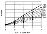
- FIG. 2 is a diagram showing the relationship between the ethanol concentration of fuel, temperature, and capacitance.
- the ECU 50 stores in advance a map as shown in FIG. 2 (hereinafter referred to as “ethanol concentration calculation map”).
- the ECU 50 can calculate the ethanol concentration of the fuel in the fuel passage 60 by applying the measured capacitance and the fuel temperature detected by the temperature sensor 14 to the ethanol concentration calculation map shown in FIG. it can.
- FIG. 3 is a diagram schematically showing the electrodes 10 and 12.
- the ECU 50 applies an alternating voltage (AC voltage) between the electrodes 10 and 12 and measures the capacitance.
- AC voltage alternating voltage
- FIG. 3 when the electrode area is S, the electrode interval is d, the fuel dielectric constant is ⁇ , and the capacitance is C, the following equation holds.
- C ⁇ ⁇ S / d (1)
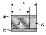
- FIG. 4 is a diagram schematically showing a state in which a part of the gap between the electrodes 10 and 12 is blocked by the gum component deposit 90. As shown in FIG. 4, the effective electrode area sandwiching the fuel is S in a normal state, but decreases to S ′ in a state where a gum component deposit 90 is generated.
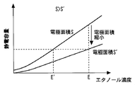
- FIG. 5 is a diagram comparing the capacitance in a normal state where there is no deposit in the gap between the electrodes 10 and 12 and the capacitance in the state where there is a deposit 90 as shown in FIG. .
- the capacitance is smaller than that in a normal case.
- the reason for this is as follows.
- the dielectric constant of the gum component is significantly smaller than that of ethanol.
- occluded by the deposit 90 an electrostatic capacitance becomes smaller than the electrode area
- the capacitance is proportional to the electrode area.
- the effective electrode area is reduced to S ', and the capacitance is accordingly reduced.
- occluded with the deposit 90 is smaller than the case where the fuel containing ethanol intervenes. For this reason, the electrostatic capacity as a whole also becomes small compared with a normal state. For this reason, in the state where the deposit 90 exists between the electrodes 10 and 12, the measured capacitance value is lower than that in the normal state.
- the correct ethanol concentration is E in FIG. 5, the ethanol concentration is erroneously detected as E 'lower than that. Therefore, when the deposit 90 is generated between the electrodes 10 and 12, it is desirable that this can be detected as an abnormality of the fuel property detection device.
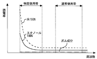
- FIG. 6 is a diagram showing the relationship between dielectric constant and frequency for three of (1) water 100%, (2) ethanol 100%, and (3) gum component. As shown in FIG. 6, the dielectric constant of water or ethanol is constant in the high frequency band (normal use band), but increases as the frequency decreases in the low frequency band (specific use band).
- electrode applied voltage when the frequency of the alternating voltage applied between the electrodes 10 and 12 (hereinafter referred to as “electrode applied voltage”) is in a low frequency band, Since the dielectric constant of ethanol is larger than that in the frequency band, the measured capacitance value is also increased.
- the dielectric constant of the gum component is constant regardless of the frequency, as shown in FIG.
- the dielectric constant of gasoline is almost constant regardless of the frequency. Therefore, the dielectric constants of the gum component and gasoline are almost the same regardless of whether the electrode applied voltage is in the low frequency band or the high frequency band.
- FIG. 7 is a diagram showing the relationship between the frequency of the electrode applied voltage (hereinafter sometimes simply referred to as “frequency”) and the capacitance.
- the solid line graph indicated by E1 is for the case where the fuel property detection device is normal and the ethanol concentration is E1
- the solid line graph indicated by E2 is that the fuel property detection device is normal and the ethanol concentration is This is the case for E2 (where E2> E1> 0).
- E2 where E2> E1> 0.
- E2 the capacitance increases as the dielectric constant of ethanol increases.
- the higher the ethanol concentration the greater the capacitance increases in the low frequency band.
- Such a frequency characteristic of the capacitance is a characteristic characteristic corresponding to the ethanol concentration when the fuel temperature is constant. According to the present embodiment, it is possible to accurately determine whether there is an abnormality in the fuel property detection device by utilizing this fact.
- the first frequency Fa in FIG. 7 is a frequency normally used for detecting the ethanol concentration of the fuel.
- the first frequency Fa is a predetermined frequency belonging to the range of the normal use band shown in FIG. That is, the first frequency Fa belongs to a high frequency band in which the dielectric constant of ethanol is constant regardless of the frequency.
- the capacitance at the first frequency Fa is Ca.
- the second frequency Fb in FIG. 7 is a predetermined frequency belonging to the range of the specific use band shown in FIG. That is, the second frequency Fb belongs to a low frequency band where the dielectric constant of ethanol is higher than that of the normal use band.
- an alternating voltage having the second frequency Fb is applied between the electrodes 10 and 12 to measure the capacitance.
- the capacitance at the second frequency Fb is Cb.
- the graphs x and y when the fuel property detection device has a characteristic abnormality and the graph E1 when the fuel property detection device is normal are discriminated. I can't.
- the frequency characteristic of the capacitance will be different from the normal case. That is, even if the capacitance Ca coincides with the graph E1 by chance at the first frequency Fa, the deviation from the graph E1 increases as the frequency decreases, and it shifts upward as in the graph x, Or shift downward.
- the ratio between the capacitance Ca at the first frequency Fa and the capacitance Cb at the second frequency Fb is Cb1 / Ca1 in the case of the ethanol concentration E1, and in the case of the ethanol concentration E2.
- the two values are different (Cb1 / Ca1 ⁇ Cb2 / Ca2). That is, the ratio between the capacitance Ca at the first frequency Fa and the capacitance Cb at the second frequency Fb varies depending on the ethanol concentration.
- the ratio between the electrostatic capacity in the low frequency band (specific use band) and the electrostatic capacity Ca in the first frequency Fa is as follows: It has a unique frequency characteristic corresponding to the ethanol concentration.
- FIG. 8 is a diagram for explaining the abnormality detection method in the present embodiment.
- the horizontal axis of FIG. 8 is the frequency, and the vertical axis is a value obtained by dividing the capacitance at each frequency by the capacitance at the first frequency Fa (hereinafter referred to as “capacitance ratio”).
- the capacitance ratio has a specific frequency characteristic corresponding to the ethanol concentration when the fuel temperature is constant.
- the curves indicated by U and L indicate the upper limit value and the lower limit value of the capacitance ratio recognized as a normal error range.
- ⁇ indicates the upper limit value of the normal range of the capacitance ratio at the second frequency Fb
- ⁇ indicates the lower limit value of the normal range of the capacitance ratio at the second frequency Fb.
- the upper limit value ⁇ and the lower limit value ⁇ also change according to the ethanol concentration and the fuel temperature.
- the ECU 50 calculates the upper limit value ⁇ and the lower limit value ⁇ of the normal range of the capacitance ratio at the second frequency Fb (hereinafter simply referred to as “capacitance ratio”) based on the ethanol concentration and the fuel temperature.
- a two-dimensional map is stored in advance. ECU 50 obtains upper limit value ⁇ and lower limit value ⁇ based on the map (hereinafter referred to as “normal ratio map”) and the current ethanol concentration and fuel temperature.
- the ECU 50 calculates the capacitance ratio Cb / Ca from the capacitance Ca measured at the first frequency Fa and the capacitance Cb measured at the second frequency Fb, and the calculated value is the upper limit value ⁇ . And the lower limit value ⁇ , it is determined that the fuel property detection device is normal, and otherwise, it is determined that the fuel property detection device is abnormal.
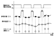
- FIG. 9 is a diagram showing an example of the time change of the frequency of the electrode application voltage and the detected values of capacitance, fuel temperature, and ethanol concentration.
- the capacitance is measured at a predetermined sampling interval.
- the capacitance (star symbol in the figure) is measured once at the second frequency Fb among the three samplings, and the first frequency Fa is measured twice.
- the time interval for frequency switching is set so that the capacitance (black circle in the figure) is measured.
- the fuel temperature and the ethanol concentration are also detected at the same sampling interval as the capacitance.
- the capacitance at the first frequency Fa (hereinafter referred to as “first capacitance”) Ca is measured, and the capacitance at the second frequency Fb (hereinafter referred to as “second capacitance”). Therefore, in this embodiment, it is confirmed that there is no change in the ethanol concentration and the fuel temperature between the measurement of the first capacitance Ca and the measurement of the second capacitance Cb. If one of them has changed, the decision was made invalid.
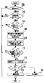
- FIG. 10 is a flowchart of a routine executed by the ECU 50 in the present embodiment in order to diagnose an abnormality of the fuel property detection device based on the above principle.
- This routine is repeatedly executed every predetermined time.
- the number of executions is represented by i.
- the basic abnormality confirmed in step 100 is an abnormality caused by a basic cause that can be diagnosed by a conventional abnormality diagnosis method, such as a circuit disconnection.
- the ECU 50 determines the presence or absence of a basic abnormality by another routine.
- abnormality diagnosis by this routine is performed when a deposit of a gum component is present between the electrodes 10 and 12, when rust (corrosion) is generated on the electrodes 10 and 12, or when the fuel property detecting device It is possible to detect a characteristic abnormality caused by a case where there is an abnormality in the circuit or an error in the detection value of the temperature sensor 14 with high accuracy. If there is a basic abnormality, the fuel property detection device is clearly recognized as abnormal, and therefore it is not necessary to execute this routine. For this reason, when it is recognized in step 100 that there is a basic abnormality, the process is terminated here.
- step 100 determines whether or not the fuel temperature T (i) detected by the temperature sensor 14 and the measured capacitance value C (i) are captured ( Step 102).
- Step 104 it is determined whether or not the current electrode application frequency is the first frequency Fa (step 104).
- the capacitance measurement value C (i) acquired in step 102 corresponds to the second capacitance Cb.
- the previous frequency is the first frequency Fa from the relationship shown in FIG. Therefore, the previous capacitance measurement value C (i ⁇ 1) corresponds to the first capacitance Ca. Therefore, in this case, the capacitance ratio Cb / Ca can be calculated by dividing the current capacitance measurement value C (i) by the previous capacitance measurement value C (i ⁇ 1). Will be ready.
- step 106 it is next determined whether or not the current fuel temperature T (i) is the same as the previous fuel temperature (i-1) (step 106). As described above, in the present embodiment, it is assumed that there is no change in the fuel temperature between the measurement of the first capacitance Ca and the measurement of the second capacitance Cb. For this reason, if the current fuel temperature T (i) and the previous fuel temperature (i-1) do not coincide in step 106, diagnosis is avoided and the process ends here.
- step 108 An upper limit value ⁇ and a lower limit value ⁇ of the range are calculated (step 108). As described above, the upper limit value ⁇ and the lower limit value ⁇ are calculated by fitting the current ethanol concentration (ethanol concentration detected last time) and the current fuel temperature T (i) to the normal ratio map. . Subsequently, the capacitance ratio Cb / Ca is calculated by dividing the current capacitance measurement value C (i) by the previous capacitance measurement value C (i ⁇ 1), and the calculated static capacitance value Cb / Ca is calculated.
- step 110 It is determined whether or not the capacitance ratio Cb / Ca is between the upper limit value ⁇ and the lower limit value ⁇ (step 110). If the capacitance ratio Cb / Ca is between the upper limit value ⁇ and the lower limit value ⁇ , it is provisionally determined that the fuel property detection device is normal (step 112). If the capacitance ratio Cb / Ca is not between the upper limit value ⁇ and the lower limit value ⁇ , it is temporarily determined that there is an abnormality in the fuel property detection device (step 114). In the present embodiment, as described above, it is assumed that there is no change in the ethanol concentration between the measurement of the first capacitance Ca and the measurement of the second capacitance Cb. The provisional determination in step 112 or 114 is because it has not been confirmed that there is no change in the ethanol concentration at this stage.
- the current capacitance measurement value C (i) is the first capacitance. It corresponds to Ca.
- the ethanol concentration E (i) is calculated by applying the fuel temperature T (i) and the capacitance C (i) acquired in step 102 to the ethanol concentration calculation map of FIG. (Step 116). This calculated E (i) is the ethanol concentration of the fuel currently between the electrodes 10 and 12. Subsequently, it is determined whether normal determination has already been made by the processing of this routine (step 118). If the normality determination has already been issued, it is not necessary to execute the subsequent processing, and the processing is terminated here. On the other hand, if the normal determination has not yet been made, it is next determined whether or not the previous frequency was the second frequency Fb (step 120). If the previous frequency is not the second frequency Fb, the process ends here.
- the previous frequency is the second frequency Fb in step 120
- the previous capacitance measurement value C (i-1) corresponds to the second capacitance Cb.
- the frequency is the first frequency Fa and the ethanol concentration is detected immediately before the previous time.
- it is next determined whether or not the ethanol concentration E (i) detected this time is the same as the ethanol concentration E (i-2) detected last time (step 122). If the current ethanol concentration E (i) and the previous ethanol concentration E (i-2) do not match, the diagnosis premise is not satisfied. Therefore, in this case, if a temporary determination is made in step 112 or 114, the temporary determination is canceled (step 124), and the processing of this routine ends here.
- diagnosis can be performed. In this case, it is first determined whether or not a provisional determination has been issued in step 112 or 114 (step 126). If a provisional determination has already been made, the provisional determination is confirmed and the main determination is made. (Step 128). On the other hand, if no provisional determination has been made, the presence / absence of an abnormality is determined in the same manner as described above. That is, first, it is determined whether or not the current fuel temperature T (i) and the previous fuel temperature (i-1) are the same (step 130), and the current fuel temperature T (i) and the previous fuel temperature are determined.
- the fuel property detection device is determined to be normal (this determination) (step 136). If the capacitance ratio Cb / Ca is not between the upper limit value ⁇ and the lower limit value ⁇ , it is determined that the fuel property detection device is abnormal (this determination) (step 138).
- 1 is added to the number of executions i (step 140).
- the frequency is switched to the second frequency Fb once every three times. However, after this determination is made, the frequency is switched to the second frequency Fb. Since it is not necessary, the switching may be stopped and the frequency may be fixed to the first frequency Fa. When the frequency is fixed to the first frequency Fa, there is an advantage that the ethanol concentration can be detected every time.
- the fuel property detection device is configured by comparing the information regarding the frequency characteristics of the capacitance inherent to the fuel properties (ethanol concentration) and the measured capacitance value. Can be diagnosed. For this reason, even when there is an abnormality (for example, accumulation of a gum component on the electrode or rusting of the electrode) in the case where the characteristics of the fuel property detection device change gradually, it is possible to make an accurate diagnosis.
- an abnormality for example, accumulation of a gum component on the electrode or rusting of the electrode
- the fuel property detection phase value for detecting the ethanol concentration of the ethanol-gasoline mixed fuel has been described as an example.
- the fuel property detection device targeted by the present invention detects the property of the ethanol-containing fuel.
- the fuel is not limited to the device, for example, a fuel having a characteristic in which the dielectric constant changes according to the frequency, such as a device for detecting the properties of ETBE (ethyl tertiary butyl ether) -containing fuel or fatty acid methyl ester-containing fuel.
- ETBE ethyl tertiary butyl ether
- the present invention can be applied generally and widely to devices that detect the properties of fuel containing components.
- abnormality diagnosis is performed based on the capacitance measured at two points of the first frequency Fa and the second frequency Fb.
- electrostatic discharge is performed at three or more points.
- An abnormality diagnosis may be performed after measuring the capacity.
- the ECU 50 corresponds to the “frequency switching means”, the “measuring means” and the “storage means” in the first invention, and the normal ratio map corresponds to the “frequency characteristic information” in the first invention. , Respectively.
- the “diagnostic means” in the first invention executes the processing of the above steps 108 and 132, thereby executing the processing in the second and third inventions.
- the “normal ratio acquisition means” executes the processing of steps 110, 112, 114, 134, 136, and 138, thereby realizing the “abnormality determination means” in the second and third inventions.
- Embodiment 2 FIG. Next, the second embodiment of the present invention will be described with reference to FIG. 11. The description will focus on the differences from the first embodiment described above, and the same matters will be simplified or described. Omitted.
- the hardware configuration of this embodiment is the same as that of the first embodiment.
- the capacitance is constantly measured by periodically switching the frequency between the first frequency Fa and the second frequency Fb.
- diagnosis is performed.
- the frequency is switched to the second frequency Fb and the capacitance is measured for diagnosis. Thereby, it can avoid switching a frequency to the 2nd frequency Fb unnecessarily.
- the diagnosis is performed by switching the frequency to the second frequency Fb before starting the engine 70 or during the fuel cut.
- FIG. 11 is a flowchart of a routine executed by the ECU 50 in the present embodiment in order to realize the above function. According to the routine shown in FIG. 11, it is first determined whether or not the fuel property detection device is activated (step 200). If the fuel property detection device has been activated, it is determined whether or not a failure diagnosis has been completed (step 202). If the fuel property detection device has not yet been activated, or if a fault diagnosis has already been completed, the processing is terminated there.
- step 204 it is next determined whether or not the current state corresponds to before the engine 70 is started or during fuel cut execution.
- the term “before engine start” as used herein refers to a state in which an engine start request is requested but has not yet been started, or a state in which the engine 70 is cranked by a starter motor, or a hybrid vehicle that uses the engine 70 and an electric motor as power sources. The engine 70 is stopped and the vehicle is running only by the power of the electric motor.
- the fuel cut includes a deceleration fuel cut that stops fuel supply to the engine 70 when the engine 70 is decelerated and the engine speed is higher than a predetermined speed, or when the vehicle speed exceeds a predetermined speed limit. Includes a high-speed fuel cut to stop the fuel supply to the engine 70. If it is determined in step 204 above that the fuel cut is not being executed but before the engine 70 is started, the processing is terminated here.
- a diagnosis can be executed.
- the fuel temperature T detected by the temperature sensor 14 and the measured value of the capacitance at the first frequency Fa are taken in, and those values are used.
- the ethanol concentration E is calculated (step 206).
- the frequency is switched to the second frequency Fb, and the capacitance (that is, the second capacitance Cb) is measured (step 208).
- step 210 determines whether the engine 70 is started or the fuel cut is completed between the time when the first capacitance Ca is acquired (step 206) and the time when the second capacitance Cb is acquired (step 208). A determination is made (step 210). When the engine 70 is started or when the fuel cut is finished, the ethanol concentration and the fuel temperature may be changed. Therefore, diagnosis is avoided and the process ends here.
- step 210 if it is determined in step 210 that the engine 70 has not been started or the fuel cut has not ended, a diagnosis can be made.
- the upper limit value ⁇ and the lower limit value ⁇ of the normal range of the capacitance ratio are calculated by applying the current ethanol concentration E and the current fuel temperature T to the normal ratio map (step). 212).
- the capacitance ratio Cb / Ca is calculated, and it is determined whether or not the calculated capacitance ratio Cb / Ca is between the upper limit value ⁇ and the lower limit value ⁇ (step 214). If the capacitance ratio Cb / Ca is between the upper limit value ⁇ and the lower limit value ⁇ , it is determined that the fuel property detection device is normal (step 216). If the capacitance ratio Cb / Ca is not between the upper limit value ⁇ and the lower limit value ⁇ , it is determined that there is an abnormality in the fuel property detection device (step 218).
- the same effect as in the first embodiment described above can be obtained, and the frequency of switching the frequency to the second frequency Fb can be minimized.
- the “frequency switching means” and the “diagnosis means” according to the fifth aspect of the present invention are realized by the ECU 50 executing the routine shown in FIG.
- Embodiment 3 the third embodiment of the present invention will be described with reference to FIG. 12. The description will focus on the differences from the above-described embodiment, and the description of the same matters will be simplified or omitted. To do.
- the hardware configuration of this embodiment is the same as that of the first embodiment. This embodiment is implemented in combination with Embodiment 1 or 2 described above.
- the electrode application frequency when diagnosing an abnormality of the fuel property detection device, it is determined whether or not the electrode application frequency is correctly switched from the first frequency Fa to the second frequency Fb. If the frequency is not correctly switched from the first frequency Fa to the second frequency Fb, the abnormality of the fuel property detection device cannot be correctly diagnosed, and abnormality diagnosis is prohibited.
- the capacitance ratio Cb / Ca becomes 1 or a value close to 1. Therefore, in this embodiment, when the capacitance ratio Cb / Ca is smaller than the predetermined determination value ⁇ , it is determined that there is an abnormality in frequency switching.
- the determination value ⁇ is a predetermined value that is larger than 1 and smaller than the lower limit value ⁇ of the normal range of the capacitance ratio. That is, ⁇ > ⁇ > 1.
- FIG. 12 is a flowchart of a routine executed by the ECU 50 in order to diagnose an abnormality in frequency switching.
- the routine of FIG. 12 is executed in conjunction with the routine of FIG. 10 or FIG. 11 described above.
- it is first determined whether or not the ethanol concentration E is greater than a predetermined threshold value EL (step 300).
- the threshold value EL is a value set in advance in order to exclude the case where the gasoline is 100% or the case where the ethanol concentration is low. If the ethanol concentration E is less than or equal to the threshold value EL, the process is terminated here without performing frequency switching abnormality diagnosis.
- step 302 when the ethanol concentration E is higher than the threshold value EL, it is determined whether or not the capacitance ratio Cb / Ca is smaller than ⁇ (step 302). As a result, when Cb / Ca ⁇ , it is determined that there is an abnormality in frequency switching (step 304). If it is determined that there is an abnormality in the frequency switching, the abnormality of the fuel property detection device cannot be accurately diagnosed, so that the abnormality diagnosis is prohibited.
- the “second diagnostic means” in the sixth and seventh aspects of the present invention is realized by the ECU 50 executing the routine shown in FIG.
- Embodiment 4 FIG. Next, a fourth embodiment of the present invention will be described with reference to FIG. 13. The description will focus on the differences from the above-described embodiments, and the description of the same matters will be simplified or omitted. To do.
- the hardware configuration of this embodiment is the same as that of the first embodiment. This embodiment is implemented in combination with any of Embodiments 1 to 3 described above.
- FIG. 13 is a flowchart of a routine executed by the ECU 50 in order to realize the above function.
- the routine of FIG. 13 is executed in conjunction with the routine of FIG. 10 or FIG. 11 described above.
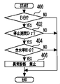
- the routine shown in FIG. 13 first, it is determined whether or not the ethanol concentration E is greater than a predetermined threshold value EH (step 400). If the ethanol concentration E is less than or equal to the threshold value EH, it can be determined that there is no possibility of phase separation, and thus the process ends here. On the other hand, if the ethanol concentration E is higher than the threshold value EH, it is next determined whether or not the stop period S from when the engine 70 was last stopped until the current start is longer than a predetermined threshold value ⁇ (step 402). .
- the threshold ⁇ is, for example, about several days to several weeks. If the engine stop period S is less than or equal to the threshold value ⁇ , it can be determined that there is no possibility of phase separation, so the process ends here. On the other hand, when the engine stop period S is longer than the threshold value ⁇ , it is next determined whether or not the moisture content W of the fuel is higher than a predetermined threshold value ⁇ (step 404).
- the moisture content W may be detected by a moisture content sensor (not shown) or estimated by a known method (for example, a method disclosed in Japanese Patent Laid-Open No. 2009-145131). If the water content W is less than or equal to the threshold value ⁇ , it can be determined that there is no possibility that phase separation has occurred, and thus the process ends here.
- phase separation determination means in the eighth and ninth inventions is realized by the ECU 50 executing the processing of steps 400, 402, and 404 described above.
- a method for eliminating such influence is prepared. May be executed.
- a mechanism for eliminating the phase separation by stirring the fuel in the vicinity of the electrodes 10 and 12 is provided, or a known method (for example, Japanese Patent Application Laid-Open By correcting the influence of the moisture content by the method disclosed in Japanese Patent No. 145131, it becomes possible to correctly execute the diagnosis of the fuel property detection device.
Landscapes
- Engineering & Computer Science (AREA)
- Chemical & Material Sciences (AREA)
- Combustion & Propulsion (AREA)
- Mechanical Engineering (AREA)
- General Engineering & Computer Science (AREA)
- Oil, Petroleum & Natural Gas (AREA)
- Health & Medical Sciences (AREA)
- Biomedical Technology (AREA)
- Investigating Or Analyzing Materials By The Use Of Electric Means (AREA)
- Combined Controls Of Internal Combustion Engines (AREA)
Abstract
Description
電界の周波数に応じて誘電率が変化する特性を有する所定燃料成分を含む燃料を使用可能な内燃機関の燃料供給経路上に設置した一対の電極間の静電容量の測定値に基づいて燃料性状を検出する燃料性状検出装置の異常を検出する装置であって、
前記両電極間に印加する交番電圧の周波数を、前記所定燃料成分の誘電率が異なる値となる複数の周波数に切り替える周波数切替手段と、
前記複数の周波数の各々において前記静電容量を測定する測定手段と、
前記燃料性状検出装置が正常な場合における、燃料性状と、前記静電容量の周波数特性との関係に関する情報である周波数特性情報を記憶した記憶手段と、
前記測定手段による測定結果と、前記周波数特性情報とに基づいて、前記燃料性状検出装置の異常を診断する診断手段と、
を備えることを特徴とする。
前記周波数切替手段は、前記両電極間に印加する交番電圧の周波数を、第1周波数と、前記所定燃料成分の誘電率が前記第1周波数の場合とは異なる値になる第2周波数とに切り替え、
前記測定手段は、前記第1周波数で交番電圧が印加されたときの前記両電極間の静電容量である第1静電容量と、前記第2周波数で交番電圧が印加されたときの前記両電極間の静電容量である第2静電容量とを測定し、
前記周波数特性情報は、前記燃料性状検出装置が正常な場合における、燃料性状と、前記第1静電容量と前記第2静電容量との比との関係に関する情報であり、
前記診断手段は、
前記燃料性状検出装置により検出された燃料性状と、前記周波数特性情報とに基づいて、前記第1静電容量と前記第2静電容量との正常な比に関する情報である正常比情報を取得する正常比取得手段と、
前記第1静電容量の測定値と、前記第2静電容量の測定値と、前記取得された正常比情報とに基づいて、前記燃料性状検出装置の異常の有無を判定する異常判定手段と、
を含むことを特徴とする。
前記正常比取得手段は、前記第1静電容量と前記第2静電容量との正常な比の上限値および下限値を取得し、
前記異常判定手段は、前記第1静電容量の測定値と前記第2静電容量の測定値との比が前記上限値から前記下限値までの範囲に入らない場合には、前記燃料性状検出装置に異常があると判定することを特徴とする。
前記第1周波数は、前記燃料性状検出装置が燃料性状を検出するために通常に使用する周波数であり、
前記第2周波数は、前記第1周波数より低く、
前記第2周波数における前記所定燃料成分の誘電率は、前記第1周波数における前記所定燃料成分の誘電率より高いことを特徴とする。
前記周波数切替手段は、前記内燃機関の始動前または前記内燃機関で燃料カットが実行中のときに前記周波数を前記複数の周波数に切り替え、その際に測定された各々の周波数での静電容量の測定値に基づいて前記診断手段が前記燃料性状検出装置の異常を診断することを特徴とする。
前記複数の周波数の各々における静電容量の測定値に基づいて、前記周波数切替手段の異常を診断する第2の診断手段を備えることを特徴とする。
前記第2の診断手段は、前記複数の周波数の各々における静電容量の測定値間の違いが所定の基準より小さい場合に、前記周波数切替手段に異常があると判定することを特徴とする。
前記燃料を構成する複数成分の相分離が発生している可能性を判定する相分離判定手段と、
前記相分離判定手段により前記相分離が発生している可能性があると判定された場合には、前記燃料性状検出装置の異常診断を実行しないことを特徴とする。
前記相分離判定手段は、前記所定燃料成分の濃度と、前記内燃機関の停止期間と、前記燃料中の含水率に関する情報とに基づいて、前記相分離が発生している可能性を判定することを特徴とする。
図1は、本発明の実施の形態1の装置構成を模式的に示す図である。図1に示す本実施形態の装置は、バイオマスに由来する燃料成分(本実施形態では、エタノールとする)を含有した燃料(本実施形態では、エタノール-ガソリン混合燃料とする)が使用される自動車に搭載され、当該燃料成分の含有濃度(本実施形態では、エタノール含有濃度)を検出する燃料性状検出装置としての機能に加えて、この燃料性状検出装置の異常を検出する異常検出装置としての機能を有している。
C=ε・S/d ・・・(1)
次に、図11を参照して、本発明の実施の形態2について説明するが、上述した実施の形態1との相違点を中心に説明し、同様の事項については、その説明を簡略化または省略する。本実施形態のハードウェア構成は、実施の形態1と同様である。
次に、図12を参照して、本発明の実施の形態3について説明するが、上述した実施の形態との相違点を中心に説明し、同様の事項については、その説明を簡略化または省略する。本実施形態のハードウェア構成は、実施の形態1と同様である。本実施形態は、前述した実施の形態1または2と組み合わせて実施される。
次に、図13を参照して、本発明の実施の形態4について説明するが、上述した実施の形態との相違点を中心に説明し、同様の事項については、その説明を簡略化または省略する。本実施形態のハードウェア構成は、実施の形態1と同様である。本実施形態は、前述した実施の形態1乃至3の何れかと組み合わせて実施される。
14 温度センサ
50 ECU
60 燃料通路
70 エンジン
90 堆積物
Claims (9)
- 電界の周波数に応じて誘電率が変化する特性を有する所定燃料成分を含む燃料を使用可能な内燃機関の燃料供給経路上に設置した一対の電極間の静電容量の測定値に基づいて燃料性状を検出する燃料性状検出装置の異常を検出する装置であって、
前記両電極間に印加する交番電圧の周波数を、前記所定燃料成分の誘電率が異なる値となる複数の周波数に切り替える周波数切替手段と、
前記複数の周波数の各々において前記静電容量を測定する測定手段と、
前記燃料性状検出装置が正常な場合における、燃料性状と、前記静電容量の周波数特性との関係に関する情報である周波数特性情報を記憶した記憶手段と、
前記測定手段による測定結果と、前記周波数特性情報とに基づいて、前記燃料性状検出装置の異常を診断する診断手段と、
を備えることを特徴とする燃料性状検出装置の異常検出装置。 - 前記周波数切替手段は、前記両電極間に印加する交番電圧の周波数を、第1周波数と、前記所定燃料成分の誘電率が前記第1周波数の場合とは異なる値になる第2周波数とに切り替え、
前記測定手段は、前記第1周波数で交番電圧が印加されたときの前記両電極間の静電容量である第1静電容量と、前記第2周波数で交番電圧が印加されたときの前記両電極間の静電容量である第2静電容量とを測定し、
前記周波数特性情報は、前記燃料性状検出装置が正常な場合における、燃料性状と、前記第1静電容量と前記第2静電容量との比との関係に関する情報であり、
前記診断手段は、
前記燃料性状検出装置により検出された燃料性状と、前記周波数特性情報とに基づいて、前記第1静電容量と前記第2静電容量との正常な比に関する情報である正常比情報を取得する正常比取得手段と、
前記第1静電容量の測定値と、前記第2静電容量の測定値と、前記取得された正常比情報とに基づいて、前記燃料性状検出装置の異常の有無を判定する異常判定手段と、
を含むことを特徴とする請求項1記載の燃料性状検出装置の異常検出装置。 - 前記正常比取得手段は、前記第1静電容量と前記第2静電容量との正常な比の上限値および下限値を取得し、
前記異常判定手段は、前記第1静電容量の測定値と前記第2静電容量の測定値との比が前記上限値から前記下限値までの範囲に入らない場合には、前記燃料性状検出装置に異常があると判定することを特徴とする請求項2記載の燃料性状検出装置の異常検出装置。 - 前記第1周波数は、前記燃料性状検出装置が燃料性状を検出するために通常に使用する周波数であり、
前記第2周波数は、前記第1周波数より低く、
前記第2周波数における前記所定燃料成分の誘電率は、前記第1周波数における前記所定燃料成分の誘電率より高いことを特徴とする請求項2または3記載の燃料性状検出装置の異常検出装置。 - 前記周波数切替手段は、前記内燃機関の始動前または前記内燃機関で燃料カットが実行中のときに前記周波数を前記複数の周波数に切り替え、その際に測定された各々の周波数での静電容量の測定値に基づいて前記診断手段が前記燃料性状検出装置の異常を診断することを特徴とする請求項1乃至4の何れか1項記載の燃料性状検出装置の異常検出装置。
- 前記複数の周波数の各々における静電容量の測定値に基づいて、前記周波数切替手段の異常を診断する第2の診断手段を備えることを特徴とする請求項1乃至5の何れか1項記載の燃料性状検出装置の異常検出装置。
- 前記第2の診断手段は、前記複数の周波数の各々における静電容量の測定値間の違いが所定の基準より小さい場合に、前記周波数切替手段に異常があると判定することを特徴とする請求項6記載の燃料性状検出装置の異常検出装置。
- 前記燃料を構成する複数成分の相分離が発生している可能性を判定する相分離判定手段と、
前記相分離判定手段により前記相分離が発生している可能性があると判定された場合には、前記燃料性状検出装置の異常診断を実行しないことを特徴とする請求項1乃至7の何れか1項記載の燃料性状検出装置の異常検出装置。 - 前記相分離判定手段は、前記所定燃料成分の濃度と、前記内燃機関の停止期間と、前記燃料中の含水率に関する情報とに基づいて、前記相分離が発生している可能性を判定することを特徴とする請求項8記載の燃料性状検出装置の異常検出装置。
Priority Applications (6)
| Application Number | Priority Date | Filing Date | Title |
|---|---|---|---|
| BR112012025338A BR112012025338A2 (pt) | 2010-04-15 | 2010-04-15 | aparelho de detecção de anormalidade para aparelho de detecção de propriedade de combustível. |
| JP2012510518A JP5278601B2 (ja) | 2010-04-15 | 2010-04-15 | 燃料性状検出装置の異常検出装置 |
| PCT/JP2010/056788 WO2011129007A1 (ja) | 2010-04-15 | 2010-04-15 | 燃料性状検出装置の異常検出装置 |
| CN2010800662007A CN102859175A (zh) | 2010-04-15 | 2010-04-15 | 燃料性状检测装置的异常检测装置 |
| US13/635,791 US20130019651A1 (en) | 2010-04-15 | 2010-04-15 | Abnormality detection apparatus for fuel property detection apparatus |
| DE112010005488T DE112010005488T8 (de) | 2010-04-15 | 2010-04-15 | Anomalieerfassungsvorrichtung für Kraftstoffeigenschaft-Erfassungsvorrichtung |
Applications Claiming Priority (1)
| Application Number | Priority Date | Filing Date | Title |
|---|---|---|---|
| PCT/JP2010/056788 WO2011129007A1 (ja) | 2010-04-15 | 2010-04-15 | 燃料性状検出装置の異常検出装置 |
Publications (1)
| Publication Number | Publication Date |
|---|---|
| WO2011129007A1 true WO2011129007A1 (ja) | 2011-10-20 |
Family
ID=44798399
Family Applications (1)
| Application Number | Title | Priority Date | Filing Date |
|---|---|---|---|
| PCT/JP2010/056788 Ceased WO2011129007A1 (ja) | 2010-04-15 | 2010-04-15 | 燃料性状検出装置の異常検出装置 |
Country Status (6)
| Country | Link |
|---|---|
| US (1) | US20130019651A1 (ja) |
| JP (1) | JP5278601B2 (ja) |
| CN (1) | CN102859175A (ja) |
| BR (1) | BR112012025338A2 (ja) |
| DE (1) | DE112010005488T8 (ja) |
| WO (1) | WO2011129007A1 (ja) |
Families Citing this family (7)
| Publication number | Priority date | Publication date | Assignee | Title |
|---|---|---|---|---|
| CN101680662B (zh) * | 2007-03-30 | 2011-05-18 | 川崎成套设备股份有限公司 | 橡胶状物质的监视装置和检测方法以及燃气轮机设备 |
| US8763587B2 (en) * | 2010-12-28 | 2014-07-01 | Toyota Jidosha Kabushiki Kaisha | Abnormality detection device for internal combustion engine |
| KR101678277B1 (ko) * | 2014-10-06 | 2016-11-21 | 주식회사 엘지화학 | 스위치 열화 검출 장치 및 방법 |
| JP6287810B2 (ja) * | 2014-12-19 | 2018-03-07 | トヨタ自動車株式会社 | 空燃比センサの異常診断装置 |
| US10196988B2 (en) * | 2015-06-05 | 2019-02-05 | Rolls-Royce Corporation | Fuel system coking sensor |
| US20180067402A1 (en) * | 2016-09-06 | 2018-03-08 | Advantest Corporation | Exposure apparatus and computer readable non-transitory storage medium |
| KR101956430B1 (ko) * | 2016-09-13 | 2019-03-08 | 현대자동차주식회사 | 디젤 연료품질 검출장치 및 그 방법 |
Citations (4)
| Publication number | Priority date | Publication date | Assignee | Title |
|---|---|---|---|---|
| JPH03249553A (ja) * | 1990-02-28 | 1991-11-07 | Katsuo Ebara | 燃料性状センサ |
| JPH0599880A (ja) * | 1991-10-09 | 1993-04-23 | Japan Electron Control Syst Co Ltd | ガソリン性状判別装置 |
| JP2009174400A (ja) * | 2008-01-23 | 2009-08-06 | Toyota Motor Corp | 内燃機関用燃料性状検出装置 |
| JP2010038052A (ja) * | 2008-08-06 | 2010-02-18 | Denso Corp | 燃料性状検出システムの異常診断装置 |
Family Cites Families (8)
| Publication number | Priority date | Publication date | Assignee | Title |
|---|---|---|---|---|
| JPH04101032A (ja) | 1990-08-15 | 1992-04-02 | Nissan Motor Co Ltd | 内燃機関の燃料供給装置 |
| JPH04278449A (ja) * | 1991-03-07 | 1992-10-05 | Meidensha Corp | 液体成分濃度測定装置 |
| US5287731A (en) * | 1993-06-11 | 1994-02-22 | Chrysler Corporation | Thermo-oxidation engine oil simulation testing |
| CN1266470C (zh) * | 2003-12-01 | 2006-07-26 | 贾柏青 | 甲烷浓度检测方法及检测装置 |
| CN101583785A (zh) * | 2006-12-18 | 2009-11-18 | 施拉德尔电子学有限公司 | 使用emf波的传播的燃料成分传感系统和方法 |
| JP2008309047A (ja) | 2007-06-13 | 2008-12-25 | Denso Corp | 内燃機関の点火制御装置 |
| US7685995B2 (en) * | 2007-06-13 | 2010-03-30 | Denso Corporation | Controller for internal combustion engine |
| JP4416033B2 (ja) * | 2007-12-12 | 2010-02-17 | 株式会社デンソー | 濃度センサ装置 |
-
2010
- 2010-04-15 WO PCT/JP2010/056788 patent/WO2011129007A1/ja not_active Ceased
- 2010-04-15 BR BR112012025338A patent/BR112012025338A2/pt not_active IP Right Cessation
- 2010-04-15 CN CN2010800662007A patent/CN102859175A/zh active Pending
- 2010-04-15 US US13/635,791 patent/US20130019651A1/en not_active Abandoned
- 2010-04-15 DE DE112010005488T patent/DE112010005488T8/de not_active Ceased
- 2010-04-15 JP JP2012510518A patent/JP5278601B2/ja not_active Expired - Fee Related
Patent Citations (4)
| Publication number | Priority date | Publication date | Assignee | Title |
|---|---|---|---|---|
| JPH03249553A (ja) * | 1990-02-28 | 1991-11-07 | Katsuo Ebara | 燃料性状センサ |
| JPH0599880A (ja) * | 1991-10-09 | 1993-04-23 | Japan Electron Control Syst Co Ltd | ガソリン性状判別装置 |
| JP2009174400A (ja) * | 2008-01-23 | 2009-08-06 | Toyota Motor Corp | 内燃機関用燃料性状検出装置 |
| JP2010038052A (ja) * | 2008-08-06 | 2010-02-18 | Denso Corp | 燃料性状検出システムの異常診断装置 |
Also Published As
| Publication number | Publication date |
|---|---|
| US20130019651A1 (en) | 2013-01-24 |
| JP5278601B2 (ja) | 2013-09-04 |
| DE112010005488T5 (de) | 2013-01-24 |
| DE112010005488T8 (de) | 2013-03-28 |
| CN102859175A (zh) | 2013-01-02 |
| BR112012025338A2 (pt) | 2016-06-28 |
| JPWO2011129007A1 (ja) | 2013-07-11 |
Similar Documents
| Publication | Publication Date | Title |
|---|---|---|
| JP5278601B2 (ja) | 燃料性状検出装置の異常検出装置 | |
| JP5240397B2 (ja) | 燃料性状検出装置の異常検出装置 | |
| US7762127B2 (en) | Method for determining the composition of a fuel mixture | |
| EP2492481A1 (en) | Soot sensor functional capability monitoring | |
| MX2014015478A (es) | Metodo para diagnosticar un catalizador de la scr. | |
| RU2621848C2 (ru) | Способ и система контроля датчика выхлопных газов | |
| CN107849994B (zh) | 用于识别燃料喷射系统的故障部件的方法 | |
| JP2010038052A (ja) | 燃料性状検出システムの異常診断装置 | |
| CN103109066B (zh) | 用于对排气传感器的功能进行监测的方法和装置 | |
| US10309324B2 (en) | Fuel property estimation device | |
| JP2018189029A (ja) | 異常監視システム | |
| US9587610B2 (en) | Method for monitoring the condition of a piezo injector of a fuel injection system | |
| JP2011179459A (ja) | 燃料性状センサの異常判定装置 | |
| US20160215749A1 (en) | Control device of internal combustion engine | |
| KR101709131B1 (ko) | 자동차 내부 연소 엔진의 연료 공급 시스템의 작동 상태를 진단하기 위한 장치 및 방법 | |
| JP2011122461A (ja) | 濃度センサ異常診断装置および内燃機関制御装置 | |
| WO2011101962A1 (ja) | 内燃機関の燃料性状判定装置 | |
| JP5569233B2 (ja) | 燃料性状検出装置 | |
| JP2010071081A (ja) | 燃料レベル検出器の異常診断装置 | |
| US9851323B2 (en) | Abnormality determination device of fuel property sensor and method of determining abnormality of the same | |
| CN106065838A (zh) | 用于识别在内燃机的燃料输送时的故障的方法 | |
| KR20160066603A (ko) | Gdi 엔진의 고압펌프 연료압력센서 고장진단방법 | |
| JP4305570B2 (ja) | 回転数センサの異常判定装置 | |
| JP2009228534A (ja) | 燃料性状判定装置、およびそれを備えた内燃機関の燃料噴射制御装置 | |
| JP4911103B2 (ja) | 内燃機関の燃料性状判定装置 |
Legal Events
| Date | Code | Title | Description |
|---|---|---|---|
| WWE | Wipo information: entry into national phase |
Ref document number: 201080066200.7 Country of ref document: CN |
|
| 121 | Ep: the epo has been informed by wipo that ep was designated in this application |
Ref document number: 10849844 Country of ref document: EP Kind code of ref document: A1 |
|
| WWE | Wipo information: entry into national phase |
Ref document number: 2012510518 Country of ref document: JP |
|
| WWE | Wipo information: entry into national phase |
Ref document number: 13635791 Country of ref document: US |
|
| WWE | Wipo information: entry into national phase |
Ref document number: 112010005488 Country of ref document: DE Ref document number: 1120100054886 Country of ref document: DE |
|
| 122 | Ep: pct application non-entry in european phase |
Ref document number: 10849844 Country of ref document: EP Kind code of ref document: A1 |
|
| REG | Reference to national code |
Ref country code: BR Ref legal event code: B01A Ref document number: 112012025338 Country of ref document: BR |
|
| ENP | Entry into the national phase |
Ref document number: 112012025338 Country of ref document: BR Kind code of ref document: A2 Effective date: 20121004 |